1
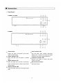
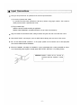
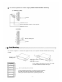
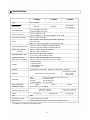
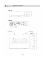
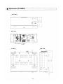
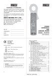
Operating Instructions
TOA 900 SERIES II
P-906MK2
P-912MK2
P-924MK2
POWER AMPLIFIER
P-906MK2
P-912MK2
P-924MK2
THE
LIGHTNING
FLASH
WITH
ARROWHEAD WITHIN A TRIANGLE IS
INTENDED TO TELL THE USER THAT
PARTS INSIDE THE PRODUCT ARE A
RISK OF ELECTRIC SHOCK TO
PERSONS.
TO REDUCE THE RISK OF ELECTRICAL
SHOCK, DO NOT REMOVE COVER.
NO USER SERVICEABLE PARTS INSIDE.
REFER SERVICING TO QUALIFIED
SERVICE PERSONNEL.
THE EXCLAMATION POINT WITHIN A
TRIANGLE IS INTENDED TO TELL
THE
USER
THAT
IMPORTANT
OPERATING
AND
SERVICING
INSTRUCTIONS ARE IN THE PAPERS
WITH THE APPLIANCE.
Please follow the instructions in this manual to obtain the optimum results from this unit.
We also recommend that you keep this manual handy for future reference.
TOA Corporation
Contents
General description
Features
Nomenclature
Front panel
Rear panel
Input connections
Output connections
Rack mounting
Operation
Volume adjustment
Installation
Servicing
Specifications
Appearance (P-906MK2/P-912MK2)
Appearance (P-924MK2)
2
2
3
4
5
6
7
8
8
8
8
9
10
11
General Description
The TOA P-906MK2, P-912MK2 and P-924MK2 Power Amplifiers deliver up to 60 watts, 120 watts and 240
watts of power respectively at less than 0.5% total harmonic distortion (THD) from 20 to 20,000 Hz
(transformerless 4-ohm output). The power amplifiers have a high-impedance direct input and an input port
(edge connector) to accept one plug-in module. Module selection is determined by application among the
TOA plug-in modules.
The power amplifiers have a low-cut switch for a cutoff frequency of 60 Hz, and an input-level switch for input
sensitivity of 1V (0 dBV) or 100mV (–20 dBV). Output terminals provide connections for 4-ohm and 8-ohm
speakers, plus 25-volt and 70-volt speaker distribution outlets. With plug-in modules, the power amplifiers
may be used as a PA amplifier.
The power amplifiers can be rack mounted by using optional rack mounting bracket MB-25B(P-906MK2,
P-912MK2) and MB-35B(P-924MK2). The optional perforated panel PF-511 provides suitable ventilation,
finished in color to match the power amplifiers.
Features
1. Wide frequency response : 20 ~ 20,000 Hz ± 1 dB
2. Low distortion and noise level
3. Excellent output regulation
4. A full range of plug-in modules
5. Self-protecting circuitry design
6. Varied output impedances : 4 ohms, 8 ohms, 25 and 70 volts
7. Input level switch (selectable 1000 mV/100 mV)
8. Portable or rack mounting type
–2–
Nomenclature
Front Panel
P-906MK2, P-912MK2
P-924MK2
Power Switch
Peak Indicator LED
Applies line power. Two-position push button
Red LED lights when amplifier approaches
switch for on/off modes.
clipping level. If steady lit, the input level control
should be turned down until the LED flashes.
Protection Indicator LED
Remains lit for about 5 seconds after power
switch is turned ON.
Master Volume Control
Adjust gain of input.
Power Indicator LED
Green LED lights when the power is switched
"ON".
Signal Indicator LED
Green LED lights when more than -30 dB signal
level is fed to the inputs by means of the master
volume control.
Normal Indicator LED
Yellow LED lights when fed to the proper signal
level.
–3–
Rear Panel
P-906MK2, P-912MK2
P-924MK2
AC Power Cord
Input Level Switch
Selects input sensitivity. Place in "1V" (0 dBV)
Connects to power source.
AC Outlet (Unswitched)
Provides AC power for auxiliary equipment with
power consumption of up to 500W.
position when normally used as a power
amplifier.
Note: The position of INPUT-LEVEL SWITCH
Impedance Select Switch
should be changed according to modules
Selects the desired impedance.
Enables unbalanced output of low impedance
when this switch is set to "DIRECT".
used or equipment connected to DIRECT
INPUT TERMINAL.
Direct Input Terminal
Output terminals
Connects directly to external equipment without
Connect to speakers.
Module Input Port
Accepts optional PLUG-IN MODULES.
Application determines type of module.
For details, refer to Plug-in Module Instruction
Manual.
Low-Cut Switch
Cut off unnecessary low frequency.
using modules.
Unbalanced 10k ohms.
AC Fuse (250V, 7A)
DC Fuse
(250V, 8A)
DC Fuse
(250V, 8A)
Protects amplifier from excessive current drain.
Replace only with same type fuse.
Refer to qualified service personnel if fuse blows
repeatedly.
–4–
Input Connections
Two types of input terminals are provided on the rear for input connections.
(1) 2P terminal (marked HOT, COM)
It is provided for direct input (unbalanced, 10k ohms) without using plug-in module. This terminal is
directly connected with a potentiometer inside.
(2) Plug-in module input
Select the desired module according to application.
DIRECT INPUT TERMINAL and MODULE INPUT are not usable simultaneously.
Plug the modules into the INPUT PORT, sliding it between the guide rails and secure with two screws.
When INPUT PORT is not occupied, cover the PORT with the blank panel and secure it with screws.
Be sure that INPUT-LEVEL SWITCH is in the proper position for the module used or the equipment
connected to DIRECT INPUT TERMINAL.
When the P-906MK2, P-912MK2 or P-924MK2 is used in combination with a mixer preamplifier or serves
as an incremental power amplifier, normally place INPUT-LEVEL SWITCH in "1V (0 dBV) position.
CAUTION: Modules should not be inserted or
removed while the amplifier is turned
on.
–5–
Output Connections
The speaker outputs of the amplifier are 4 ohms, 8 ohms, 25V and 70V.
Connect speakers to any one of these outputs.
Class 2 wiring may be used.
There are two types of output ;
8 ohms, 25V and 70V via output (matching) transformer
4-ohm direct output.
The connecting method differs in each case. Refer to the following diagrams.
Note : Impedances indicated below imply total speaker system (load) impedances.
To connect speakers to outputs of : 8 ohms, 25V or 70V (BALANCED OUTPUT)
(P-906MK2/P-912MK2)
8-ohm
10.4-ohm(P-906MK2)/
83-ohm(P-906MK2)/
5.2-ohm(P-912MK2)
41-ohm(P-912MK2)
70V line
25V line
Loosen the screw.
Place the impedance switch in 8-ohm position.
Tighten the screw.
(P-924MK2)
8-ohm
2.6-ohm
25V line
Insert shorting bar between 4
21-ohm
70V line
and OT lN.
Note : Low-cut switch should be in "CUT" position.
Cut off unnecessary low frequency in TRANS OUTPUT to obtain best acoustic condition. The
900MK2 series amplifiers are characteristically flat even in the low frequency range. Thus, in TRANS
OUTPUT the acoustic effect and frequency-response characteristics may be altered.
–6–
To connect speakers to 4-ohm output (UNBALANCED DIRECT OUTPUT)
(P-906MK2/P-912MK2)
4-ohm
Loosen the screw.
Place the impedance switch in 4-ohm position.
Tighten the screw.
(P-924MK2)
Remove shorting bar.
4-ohm
Rack Mounting
To mount the amplifier in a standard 19" equipment rack, use the optional MB-25B, MB-35B rack mounting
bracket.
Remove 4 screws
securing case.
MB-25B (P-906MK2, P-912MK2)
MB-35B (P-924MK2)
Amplifier
Fix the brackets with attached 4 screws. The length
of screws should not exceed 12mm (1/2").
PF-511 perforated panel (1-unit size)
Use the perforated panel PF-511 to provide space for ventilation,
when two or more units are mounted in an equipment rack.
Contact your local TOA dealer for the perforated panel PF-511.
–7–
Operation
After all connections are made, turn power switch ON, illuminating the Power Indicator LED. The amplifier
comes into operation approximately 5 seconds after the power is turned on.
Volume Adjustment
Obtain desired output level by adjusting the master volume control. For normal music playing or
announcement, adjust the master volume control until the normal LED intermittently lights. Sound quality is
deteriorated when the peak LED remains lit.
When the power amplifier is used in combination with a mixer preamplifier, adjust total gain at the mixer
preamplifier with the gain setting of power amplifier at maximum.
Never block ventilation holes.
The amplifier should never be placed in areas
exposed to direct sunlight.
with high humidity or dust levels.
with high ambient temperatures.
susceptible to vibration.
with poor ventilation.
adjacent to heat-generating equipment.
CAUTION : Do not remove the case or you may encounter an electric shock.
Note : When the temperature of heat sink exceeds 105 °C the protection circuit is activated and the output is
disconnected from the circuit. Output is automatically restored when the temperature return to normal
operating parameter.
Servicing
Unpacking
Upon receipt of the amplifier shipment, please inspect for any damage incurred in transit. If damage is
found, please notify your local TOA representative and the transportation company immediately.
State date, nature of damage, whether any damage was noticed on the shipping container, prior to
unpacking. Please give waybill number of shipping order.
Failure
Should amplifier fail, contact your nearest TOA authorized contractor or service center.
–8–
Specifications
P-906MK2
Type
Frequency Response
P-924MK2
120W RMS
(D) 240W RMS,
(T) 220W RMS
Power amplifier
Output Power
Power Band Width
P-912MK2
60W RMS
(D) 20 ~20,000 Hz, 0.5% THD
(T) 50 ~20,000 Hz, 0.5% THD
(D) 20 ~20,000 Hz, ± 1 dB
(T) 20 ~15,000 Hz, ± 1 dB, (T) 20 ~20,000 Hz, +1 dB, -3 dB
Total Hamonic Distortion
0.01% at 1 kHz, rated output
Inputs
One Input Ports : Port accepts any input module except T-01.
One Direct Input
Note : Use of direct input prohibits use of modular input port.
Input Sensitivity/Impedance
Input Port : 100 mV or 1000 mV (switchable)/10k ohms
Direct Input : 100 mV or 1000 mV (switchable)/10k ohms
Outputs (T)=Transformer
(D)=Direct
Main (T) : 8 ohms, 25 & 70 volts, balanced
Main (D) : 4 ohms, unbalanced
Output Regulation (1 kHz)
(D) Less than 0.5 dB, no load to full load
(T) Less than 1.0 dB, no load to full load
Signal to Noise Ratio
(Band Pass 20 -20,000 Hz)
Input level switch in 0 dBV (1000 mV) position : 108 dB
Input level switch in -20 dBV (100 mV) position : 90 dB
Controls
1
1
1
1
Indicators
1 Power LED, 1 Protect LED, 1 Signal LED, 1 Normal LED, 1 Peak LED
Input gain control
Input level switch
Power ON/OFF switch
Low-Cut switch
Protection
Connectors
Self-protection, with AC fuse (inside)
Input
Output
AC outlet
AC power cord/plug
Power Consumption
Temperature Range
Card-edge connector and screw-terminal strip
Screw-terminal strip
3-pin grounding type
SJT, 3-prong type
100W
180W
120V/3A
-10°C~+60°C [12°F~140°F]
420 x 99.1 x 358 mm
Dimensions (W) x (H) x (D)
Weight
Self-protection, with 2AC
fuses (1 inside)
and 2DC fuses
[16.5 x 3 . 9 x 14.1 in.]
10.9kg [24.0 Ib.]
9.1 kg [20.1 Ib.]
420 x 151.3 x 334.2 mm
[16.5 x 6.0 x 13. 2 in.]
19.5kg [43 Ib.]
Color
Black
Standard Accessories
1 Volume control cover (YA-920)
Other Features
Output disconnected for approx. 5 seconds after switching power on.
* Specifications are subject to change without notice.
–9–
Appearance (P-906MK2/P-912MK2)
Front View
420
Rear View
320
17
– 10 –
358
Side View
Top View
Appearance (P-924MK2)
Front View
420
Rear View
Top View
17
– 11 –
334.2
298.5
Side View
TOA Corporation
KOBE, JAPAN
PRINTED IN TAIWAN
133-12-116-60