1
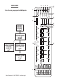
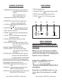
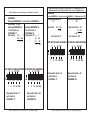
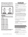
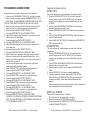
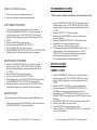
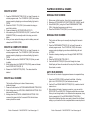
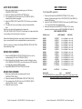
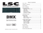
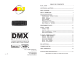
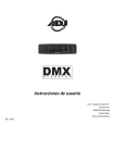
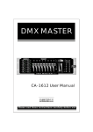
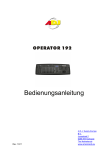
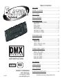
Table of Contents
FLOW CHART...........................................................................................1
CONTROLS & FUNCTIONS.......................................................................2
REAR CONTROLS.........................................................................................4
DMX-512 Addressing..............................................................................4
PROGRAMMING SCENES........................................................................8
Programming Scenes Review:.......................................................9
scene copy:.......................................................................................10
SCENE EDITING:...................................................................................10
DELETE SCENE :.................................................................................10
RESET ALL SCENES:............................................................................10
COPY BANK of scenes:.................................................................11
DELETE BANK of scenes:................................................................11
PROGRAMMING CHASES.....................................................................12
EDITING CHASES....................................................................................12
INSERT a STEP:....................................................................................12
DELETE a STEP:....................................................................................13
DELETE a COMPLETE Chase:...........................................................13
DELETE all Chases:..........................................................................13
User Instructions
PLAYBACK SCENES & CHASES...............................................................14
MANUAL RUN SCENES:....................................................................14
MANUAL RUN CHASES:....................................................................14
AUTO RUN SCENES:..........................................................................14
AUTO RUN chaseS:.........................................................................15
MUSIC RUN SCENES:........................................................................15
MUSIC RUN CHASES:..........................................................................15
Midi operation.......................................................................................16
MIDI
CAPABLE
DMX-512
Elation Professional®
©
rev. 4/04
6122 S. Eastern Ave.
Los Angeles Ca. 90040
www.elationlighting.com
Trouble shooting.................................................................................18
cable termination................................................................................18
dip switch DMX ADDRESS CHARTS........................................................20
Specifications are subject to change without notice!
10
12
FADE TIME
Tapsync
Display
Bank-copy
Music
Midi
Rec
Auto
Del
11
Chase 6
BLACKOUT
9
8
Chase 5
7
Chase 4
Chase 3
Chase 2
Program
5
PROGRAM SCENES
14 13
SPEED
Page
Select
16
15
13
5
5
pg 12
12
4
up to 6 of 240 scenes
10
9
up to 240
7
8
9
10
11
12
1
2
3
4
5
6
SCANNERS
1
1
pg 14
Elation Professional® - DMX OPERATOR User Manual page 1
11
2
PLAYBACK CHASES
1
2
3
pg 14
PROGRAM CHASES
4
8 AT A TIME
30 BANKS OF 8
3
PLAYBACK SCENES
SCENES
2
6
pg 8 & 9
14
6
(up to 240)
15
7
7
8
8
Page A
address
Fixtures
pg 4 to 7
Page B
3
4
This is the order you program the DMX Operator.
BANK Chase 1
6
FLOW CHART
CONTROLS & FUNCTIONS
1. Scanner BUTTONS - Used to Select any or all of 12 fixtures This is what selects which DMX channels go to the fixtures.
Scanner 1 controls Channel 1 to 16
Scanner 2 controls Channel 17 to 32
See addressing of fixtures on page 7 for more information
2. Scene buttons - Used to store Scenes in program mode or
playback your scenes in playback mode
3. LCD display - Displays values and settings depending on the
chosen function.
4. Bank Buttons ( or )- Selects which Bank you want to use.
(there are 30 selectable banks total.)
5. CHASE - Used to select chases (1-6).
6. PROGRAM - Used to activate program mode Display blinks when
activated.
7. MIDI / REC - Used to control MIDI operation or to Record each
step for Scene and Chases.
8. AUTO/DEL- Select AUTO speed in chase mode or Deletes
Scenes and or chases .
9. MUSIC / BANK COPY- Used to trigger sound activation in Chase mode or to copy a bank of scenes from one to another in Program Mode
10. BLACKOUT - Disables or enables all channel outputs
11. TAP SYNC / DISPLAY - In Auto Chase mode used to change rate of chase also to change LCD Display in Manual Chase.
12. FADE TIME SLIDER - Used to adjust the FADE TIME. Fade Time is
the amount of time it takes the DMX Operator to completely change from one scene to another.
For example; if the fade time slider is set to 0 (zero) a scene change will
be instant. If the slider is set to ‘30s’ it will take the DMX Operator 30 seconds to complete the change from one scene to the next.
13. SPEED SLIDER - Used to adjust the rate of chase speed in Auto
Mode.
14. PAGE SELECT - Used to select faders between PAGE A (1-8) and
PAGE B (9-16) of each Scanner Button
15. FADERS (1-8) - Used to adjust the intensity from 0% to 100% or DMX
output level from 0 to 255 of each channel
Elation Professional® - DMX OPERATOR User Manual page 3
REAR CONTROLS
16. MIDI IN- Receives MIDI data.
17. DMX POLARITY SELECT- Changes the polarity setting of the DMX output.
18. DMX OUT- Used to send DMX signal to fixtures or Packs.
19. DC INPUT- Accepts a DC 9~12V, 300 mA minimum, power
supply.
17
16
MIDI IN
18
DMX POLARITY
SELECT
1:GND
2:DATA 3:DATA +
19
DMX OUT
DC INPUT
-
1:GND
+
2:DATA +
3:DATA -
+9V-+12V 300mA Min.
DMX512 Addressing
When addressing your fixtures follow the Starting
address in this book not the addressing found in your
fixture manual
DMX 512 is a type of protocol that sends out up to 512 multiplex
channels at once down a common cable. Each channels has a value
from 0 to 255. You set the address for each receiver(fixture) by using
Dip switches or some type of digital readout
Each Dip switch has an ADDRESS based on binary code.
Dip switch
#1 #2 #3 #4 #5 #6 #7 #8 #9
Value
1 2 4 8 16 32 64 128 256
You seLECT the ADDRESS wanted by ADDING the TOTAL OF
Dip switches ON.
Dip switch #10 is not used with DMX but normally to select some
Function ie: Master / Slave, Sound Activation or to receive DMX
Control.
Elation Professional® - DMX OPERATOR User Manual page 4
Most fixtures start receiving on the address selected
EXAMPLE:
Setting ADDRESS at 1 unit starts at CHANNEL 1
Dip switch # 1 on
Setting ADDRESS for
Setting ADDRESS for
17 unit starts at 49 unit starts at
CHANNEL 17
CHANNEL 49
Dip switch
#1=
1
Dip switch # 1 =
1
“
# 5 = +16
“
5 = 16
= 17
“
6=
32
=
49
Some units start receiving one more than the address selected.
Example: Elation Patend Light, Elation Professional Mighty Scan
EXAMPLE:
Setting ADDRESS at 0 unit starts at CHANNEL 1 all Dip switches OFF
Setting ADDRESS for
17 Dip switch
# 5 = 16
= 16
unit starts at 17
2
1 2 3 4 5 6 7 8 9 10
1
4
16 64 256
Dip switch total = 17
unit starts at
CHANNEL 17
ON
1 2 3 4 5 6 7 8 9 10
1
4
8
4
2
32 128
1 2 3 4 5 6 7 8 9 10
1
ON
Dip switch # 5 = 16
6 = 32
= 48
unit starts at 49
16 64 256
Dip switch total = 16
unit starts at
CHANNEL 17
ON
8
32 128
1 2 3 4 5 6 7 8 9 10
1
4
16 64 256
Dip switch total = 48
unit starts at
CHANNEL 49
16 64 256
Dip switch total = 49
unit starts at
CHANNEL 49
Elation Professional® - DMX OPERATOR User Manual page 5
dip switch DMX ADDRESS dip switch DMX ADDRESS
ON
dip switch DMX ADDRESSdip switch DMX ADDRESS
2
8 32 128
2
8 32 128
Setting ADDRESS for
49
Elation Professional® - DMX OPERATOR User Manual page 6
While DMX 512 is the standard used to control lighting, at this time,
there are some differences you should know about. One is pin configuration. The DATA + And DATA- are reversed. This can be corrected
by using the reversal switch on the DMX Operator. If you have some
fixtures from each polarity use adapter Z-DMXADAPT between the fixtures.
TYPE 1
3 Data -
XLR MALE SOCKET
Data - 2
3 Data +
1 Ground
DATA IN
PROGRAMMING SCENES
PRESS AND HOLD PROGRAM BUTTON (FIG. 6) for three (3) seconds to activate program mode. The LCD Display (fig.3) will indicate your in program mode by displaying a continuous fast blinking light next to ‘PROG.
2.Select a fixture to program, by pressing any or all SCANNER buttons 1 to 12 (fig2).
TYPE 2
XLR MALE SOCKET
Data+ 2
1.
1 Ground
DATA IN
Addressing Fixtures
In order to have individual control of each fixture with
the DMX operator Fixture addresses should be addressed
as follows.
Scanner Button # 1 starts at 1
Scanner Button # 2 starts at 17
Scanner Button # 3 starts at 33
Scanner Button # 4 starts at 49
Scanner Button # 5 starts at 65
Scanner Button # 6 starts at 81
Scanner Button # 7 starts at 97
Scanner Button # 8 starts at 113
Scanner Button # 9 starts at 129
Scanner Button # 10 starts at 145
Scanner Button # 11 starts at 161
Scanner Button # 12 starts at 177
If you are not sure how to set the starting address of your
Fixture refer to Chart on pages 20 & 21 of manual.
Elation Professional® - DMX OPERATOR User Manual page 7
3.Adjust the faders to the desired settings of the fixture or fixtures your programming (i.e. Color, Gobo, Pan, Tilt, Speed, etc.), by adjusting the fader values. Use the PAGE A B Button if your Fixture has more than eight channels. When selecting from Page A to B you have to move Sliders to activate channels
4.Once you’ve reached your desired setting and or position for the Fixture, you can press the SCANNER BUTTON you were adjusting this stops adjustment of that Fixture(s). You then press another Scanner Button to select another Fixture to adjust.You can adjust more than one fixture at a time by selecting more than one Scanner Button at a time
5. Repeat steps 2 and 3 until all the lights are where you want.
6. When entire scene is set to your liking, press and release the
MIDI / REC Button (fig 7.) .
8. Then press a Scene button 1-8 (fig 2) to store this scene. ALL LEDS BLINK 3 TIMES The LCD will display the bank and scene where your
scene was stored.
9. Repeat steps 2-8 to record your first 8 scenes.
You can copy the settings from one scanner button to another in case you
want to add more lights to your show. just press and hold the scanner button
you want to copy then press the Scanner button you want to copy to
10. Now use the UP and DOWN BANK buttons (fig.4). to record more
banks of scenes. There are 30 banks you can store up to 8 scenes
per a bank for a total of 240 scenes.
11. To exit programming mode press and hold the PROGRAM BUTTON (FIG.6) for 3 seconds.
When you exit programming Blackout LED is on press BLACKOUT BUTTON
to de-activate blackout.
Elation Professional® - DMX OPERATOR User Manual page 8
Programming Scenes Review
Programming Scenes continued
To review this is how you would create a simple 4 step box pattern
1. Press and hold PROGRAM BUTTON (FIG. 6) for three (3) seconds
2.Select a fixture(s) to program using the SCANNER buttons 1 to 12
Note: when you are beginning it may be easier to use four
cups or other objects placed on the floor as a guide.
3.Adjust the faders to the desired Color, Gobo, then using the Pan, Tilt, adjust the mirrors to go to the bottom corner of the dance floor.
4. Press and release the MIDI / REC Button (fig 7.).
5. Then press Scene button 1ALL LEDS BLINK 3 TIMES
6. Adjust the Pan faders to adjust the mirrors to go across to the other
bottom corner of the dance floor.
7. Press and release the MIDI / REC Button (fig 7.).
8. Then press Scene button 2 ALL LEDS BLINK 3 TIMES
9. Adjust the tilt fader to adjust the mirrors to go up to the top corner of the dance floor.
10. Press and release the MIDI / REC Button (fig 7.).
11. Now press Scene button 3 ALL LEDS BLINK 3 TIMES
12. Adjust the Pan fader to adjust the mirrors to go across to the other
top corner of the dance floor. By pressing Scene buttons 1 to 4 in order you should have a box pattern. If you have a problem refer to Trouble shooting. page1 8
You can now use these scenes to make scenes 5-8 Same box patterns with different colors and gobos
1. Press SCENE BUTTON 1 make color and gobo adjustments
2. Press and release the MIDI / REC Button (fig 7.).
3. Then press Scene button 5 ALL LEDS BLINK 3 TIMES
4. Press SCENE BUTTON 2 make color and gobo adjustments
5. Press and release the MIDI / REC Button (fig 7.).
6. Then press Scene button 6 ALL LEDS BLINK 3 TIMES
7. Press SCENE BUTTON 3 make color and gobo adjustments
8. Press and release the MIDI / REC Button (fig 7.).
9. Then press Scene button 7 ALL LEDS BLINK 3 TIMES
10. Press SCENE BUTTON 4 make color and gobo adjustments
11. Press and release the MIDI / REC Button (fig 7.).
13. Then press Scene button 8 ALL LEDS BLINK 3 TIMES
This gives you 8 scenes 2 different colored box patterns.
Once you have recorded all the scenes you can now go to programming chases pg 12
This function allows you to copy the settings of one scene to another.
1. Press the PROGRAM BUTTON (FIG. 6) for three (3) seconds to
activate program mode. The LCD Display (fig.3) will indicate
program mode by displaying a continuous fast blinking dot next to ‘PROG.’
2. Use the UP and Down bank buttons (fig.4) to locate the bank that contains the scene you wish to copy.
3. Press the SCENE button (fig.5), that contains the scene you want to copy.
4. Use the UP and Down bank buttons (fig.4) to select the bank you want to copy the scene to.
5. Press the MIDi / reC button (fig.7) followed by the scene button (fig.5) you wish to copy to.
Elation Professional® - DMX OPERATOR User Manual page 9
scene copy:
SCENE EDITING:
This function allows you to make changes in a scene after it has been
programmed.
1. Press the PROGRAM BUTTON (FIG. 6) for three (3) seconds to
activate program mode. The LCD Display (fig.3) will indicate
program mode by displaying a continuous fast blinking dot next to ‘PROG.’
2. Use the Up and down bank buttons (fig.4) to select the bank that stores the scene you wish to edit.
3. Select the scene you want to edit by pressing its SCENE BUTTON (FIG.5).
4. Use the FADERS (FIG.15) to make your desired adjustments.
5. Once you’ve made your changes, press the MIDI / REC button (fig.7) followed by the scene button (fig.2) that corresponds to the scene your editing. This will store the edited scene back into memory.
Be sure to selected the same scene you selected in step 4, otherwise you may accidentally record over an existing scene.
RESET ALL SCENES:
This function will erase all scenes in all Banks
(ALL Channels of all scenes are reset to 0 output).
1. Press and hold down the PROGRAM button (fig.6)
2. While holding down the Program button (fig.6), press and hold the BANK DOWN button (fig.4).
Elation Professional® - DMX OPERATOR User Manual page 10
RESET ALL SCENES Continued:
3. Disconnect the power and release the buttons.
4. Reconnect the power, all scenes should be erased
COPY BANK of scenes:
This function will copy the settings of one bank to another.
1. Press the PROGRAM BUTTON (FIG. 6) for three (3) seconds to
activate program mode. The LCD Display (fig.3) will indicate
program mode by displaying a continuous fast blinking dot next to ‘PROG.’
2.Select the BANK (fig.4) you want to copy
3. Press and release the MIDI/REC button (fig.7)
4.Select the BANK (fig.4) you wish to record to.
5. Press MUSIC/BANK COPY button (fig.9), The LCD display (fig.3) will flash briefly to indicate the function has been completed.
DELETE BANK of scenes:
1. Press the PROGRAM BUTTON (FIG. 6) for three (3) seconds to
activate program mode. The LCD Display (fig.3) will indicate
program mode by displaying a continuous fast blinking dot next to ‘PROG.’
2.Select the BANK (fig.4) you want to delete
3. Press and hold the AUTO/DEL button (fig.8).
4. While holding down the AUTO/Del button (fig.8) press and hold the MUSIC/BANK COPY button (fig.9) at the same time.
5. Release both buttons at the same time, the LCD display (fig.3) should flash momentarily to indicated the function completion.
DELETE SCENE :
This function will reset all DMX Channels in a single SCENE back to 0.
1. While pressing and holding AUTO/DEL(fig.8), Press and release the SCENE Button (fig.2) 1-8 you want to delete.
Elation Professional® - DMX OPERATOR User Manual page 11
PROGRAMMING CHASES:
Note: You
must program scenes before you can program chases.
1. Press the PROGRAM BUTTON (FIG. 6) for three (3) seconds to
activate program mode. The LCD Display (fig.3) will indicate
program mode by displaying a continuous fast blinking dot next to ‘PROG.’
2.Select any CHASE 1 to 6 (fig 5) to program.
3.Select a desired SCENE (fig2) from any bank that has been
previously recorded.
4. Press the MIDI/REC button (fig.7). All LED’s blink 3 times
5. Repeat steps 3 & 4 as many times as you want.
You may store up to 240 steps into one chase.
6. To exit programming press the PROGRAM BUTTON (FIG. 6) for three (3) seconds to de-activate program mode. The LCD Display (fig.3) will indicate blackout mode by displaying a
continuous fast blinking dot next to ‘Blackout.’
You May now playback the Chase Recorded Pg. 14
EDITING CHASES
INSERT a STEP:
1. Press the PROGRAM BUTTON (FIG. 6) for three (3) seconds to
activate program mode. The LCD Display (fig.3) will indicate program mode by displaying a continuous flashing light next to ‘PROG.’
2.Select the CHASE 1 to 6 (fig 5) you wish to add a step to.
3. Press and release the TAP SYNC/DISPLAY button (fig.11).
The Display will now change to the step you are now in.
4.After selecting the TAP SYNC/DISPLAY (fig.11) use the UP and DOWN Buttons, to manually scroll to the step you wish to insert a step after.
5. Press MIDI/REC (fig.7) the LCD will read one step number higher
6. Press the Scene Button you want to insert
6. Press MIDI/REc (fig.7) again to insert new step.
7. Press and release the TAP SYNC/DISPLAY (fig.11) to return the dis
play to normal operation.
Elation Professional® - DMX OPERATOR User Manual page 12
DELETE a STEP:
1. Press the PROGRAM BUTTON (FIG. 6) for three (3) seconds to
activate program mode. The LCD Display (fig.3) will indicate
program mode by displaying a continuous flashing light next to ‘PROG.’
2.Select the CHASE 1 to 6 (fig. 5) that contains the step you
would like to delete.
3. Press and release the TAP SYNC/DISPLAY (fig.11).
4.After selecting the TAP SYNC/DISPLAY (fig.11) use the UP and DOWN Buttons, to manually scroll to the step you wish to
delete.
5. When you have reached the step you wish to delete, press and release the Auto/Del (Fig.8).
DELETE a COMPLETE Chase:
1.
2.
3.
4.
Press the PROGRAM BUTTON (FIG. 6) for three (3) seconds to
activate program mode. The LCD Display (fig.3) will indicate
program mode by displaying a continuous flashing light next to ‘PROG.’
Press and hold down the CHASE button (fig.5) that you want
to delete.
While holding down the CHASE button (fig.5) press and release the AUTO/DEL button (fig. 9).
Release the CHASE button (fig.5). The chase should be
deleted.
PLAYBACK SCENES & CHASES
MANUAL RUN SCENES:
1. When power is first turned on, the unit is in manual scene mode.
2. Make sure AUTO & MUSIC LED’s buttons (figs. 8 and 9) are off .
3. Select BANk (fig.4), using the UP and DOWN bank Buttons (fig.4), that store the scenes you wish to run.
4. Press the SCENE Buttons (fig.2) to run the scene you selected.
MANUAL RUN CHASES:
This function will allow you to manually step through all scenes in any Chase.
1. Press the PROGRAM BUTTON (FIG. 6) for three (3) seconds to
activate program mode. The LCD Display (fig.3) will indicate
program mode by displaying a continuous fast blinking dot next to ‘PROG.’
2.Execute a chase by selecting one of the eight chase buttons (fig.5).
5. Press the taP/SYNC Button (fig.11).
6. Use the Bank Buttons (fig.4) to scroll through the chase.
Note:Display will show the number of the step in the Chase not the Scene bank or number
AUTO RUN SCENES:
This function will run a bank of programmed scenes in a sequential loop.
DELETE all Chases:
1.
2.
3.
This function will allow you to clear all chase memory
(delete all chases).
Press and hold down the Auto/del& BankDown buttons fig.8
While holding down the Auto/del & BankDown buttons fig.8
disconnect the power.
Holding down the Auto/del & BankDown buttons fig.8
reconnect the power hold for 3 seconds LED’s blink all chase
memory should be erased.
Elation Professional® - DMX OPERATOR User Manual page 13
1. Press the aUTO/DEL (fig.8) to activate Auto Mode. A flashing light in the lcd display (fig.3) will indicate auto mode.
2. Use the UP and DOWN bank Buttons (fig.4), to select a bank of scenes to run.
3. After selecting the bank of scenes you want run, you can use the Speed (fig.13) and Fade (fig.12) sliders to adjust the scene chase
Note: you can change banks, to run different scene sequences, at any time by pressing the UP and DOWN bank Buttons (fig.4).
Note: when Adjusting fade time never make it slower than the Speed setting or your scene will not be completed before a new step is sent.
Elation Professional® - DMX OPERATOR User Manual page 14
AUTO RUN chaseS:
1.Select your desired chase by pressing any or all of the six
chase buttons (fig.5).
2. Press and release the Auto/Del Button (fig.8).
3. The corresponding LED will flash in the LCD display (fig.3)
indicating Auto mode is engaged.
4.Adjust the speed (fig.13) and fade (fig.12) times to your desired settings.
5. The chase will now run according to your set speed and fade time.
Note: You can override the speed and by tapping the
tap sync /display button (fig.11) three times, the chase would then
run according to the time interval of your taps.
Note: when Adjusting fade time never make it slower than the Speed setting or your scenes will not be completed before a new step is sent.
Note: If you want to include all the Chases Press auto/DEL button
before selecting Chase.
MUSIC RUN SCENES:
1. Press the Music/Bank-copy button (fig.9) to turn on the
corresponding LED in the lcd display (fig.3).
2. Select the bank that holds the scenes you wish to chase by using UP or DOWN Buttons (fig.4), you may also use a MIDI controller to change the scenes (see MIDI operation).
3. Press MUSIC/BANK COPY Button (fig.9) to exit.
MUSIC RUN CHASES:
1.Select your desired chase by pressing one of the six
chase buttons (fig.5).
2. Press and release the music/bank-copy Button (fig.9).
3. The corresponding LED will flash in the LCD display (fig.3)
indicating Music mode is engaged.
4. Chase will now run sound.
Elation Professional® - DMX OPERATOR User Manual page 15
Midi operation
To Activate MIDI operation:
1.
2.
3.
Press and hold down the MIDI/REC button (fig.7) for three seconds, the last two digits of the LCD Display (fig.3) will BLINK to indicate MIDI setting.
Use the Up and Down Buttons (fig.4) to select the MIDI Channel 1 to 16 you would like to be activated from.
Press and hold down the MIDI/REC button (fig.7) for three seconds,to exit this function and MIDI operation is now on.
MIDI CHANNEL SETTING
BANK (Octave)
BANK
BANK
BANK
BANK
BANK
BANK
BANK
BANK
BANK
BANK
BANK
BANK
BANK
BANK
BANK
NOTE NUMBER
1 2 3
4
5
6
7
8
9
10
11
12
13
14
15
00 TO 07
08 TO 15
16 TO 23
24 TO 31
32 TO 39
40 TO 47
48 TO 55
56 TO 63
64 TO 71
72 TO 79
80 TO 87
88 TO 95
96 TO 103
104 TO 111
112 TO 119
1
1
1
1
1
1
1
1
1
1
1
1
1
1
1
CHASES
120 TO 125
1 to 6 Chases
BLACK OUT
126 to
to
to
to
to
to
to
to
to
to
to
to
to
to
to
8
8
8
8
8
8
8
8
8
8
8
8
8
8
8
of
of
of
of
of
of
of
of
of
of
of
of
of
of
of
FUNCTION
Bank 1
Bank 1
Bank 1
Bank 1
Bank 1
Bank 6
Bank 7
Bank 8
Bank 9
Bank10
Bank11
Bank12
Bank13
Bank14
Bank14
on or off
on or off
on or off
on or off
on or off
on or off
on or off
on or off
on or off
on or off
on or off
on or off
on or off
on or off
on or off
BLACKOUT
The DMX OPERATOR only receives MIDI notes and you may have to transpose your keyboard to find the proper notes
Elation Professional® - DMX OPERATOR User Manual page 16
Trouble shooting
Specifications
All Scenes,Chases, and Options retained by battery back up
3 space 19” rack mount case
Reversible DMX polarity out put
MIDI input to control Chase and scene s
192 DMX Channels output 12 Scanners buttons (up to 16 Channels each)
6 Chases of 240 steps
240 Scenes in 30 Banks
Audio Chase
Speed and Fade time adjustments
Cable Termination
When total run of Control cable is 90” or over it is necessary to
terminate the Cable. This can be accomplished as follows.
1: Many Fixtures have some type of built in termination either auto-matic or
by some type of function switch,select this in the last fixture in the link.
2: Make or buy a Termination Plug and insert it into the last Fixture in the
link.
To make a termination plug use a Male XLR plug and solder a 90 to 120
ohm 1/4 watt resistor between pins 2 & 3 of the plug.
Mirrors don’t respond when I move faders
Make sure address is correct. See Chart pages 20, 21
Make sure speed is adjusted, if available, for faster
movement.Not all Fixtures have a speed adjustment.
If total of XLR cable is more than 90 feet make sure it is
terminated properly.
Colors don’t respond when I move faders
Make sure address is correct. See Chart pages 20 21
If total of XLR cable is more than 90 feet make sure it is
terminated properly.
Scenes don’t playback after I record them
Make sure to press MIDI/RECORD Button, before pressing scene Button. LED’s should blink after pressing each
Scene Button.
Make sure you are in the correct Bank that has scenes
recorded.
Scenes don’t playback correctly like I recorded them
Was Scanner for all fixtures recorded.
Is Fade Time to long for Speed selected?
Make sure you are in the correct Bank that has scenes
recorded
If total of XLR cable is more than 90 feet make sure it is
terminated properly.
Chases don’t playback after I record them
Make sure to press MIDI/RECORD Button, after pressing Elation Professional® - DMX OPERATOR User Manual page 17
scene Button. LED’s should blink after pressing MIDI/RECORD Button.
Make sure you are in the correct Chase that has steps
recorded
If in Auto Mode, is It selected in Display. Did you adjust Speed after selecting Auto?
Is Fade Time to long for Speed Selected?
If total of XLR cable is more than 90 feet make sure it is
terminated properly.
Elation Professional® - DMX OPERATOR User Manual page 18
dip switch DMX ADDRESS CHART
dip switch DMX ADDRESS CHART
WHEN STARTING ADDRESS IS ONE MORE THAN
SELECTED IE: AMERICAN DJ MIGHTY SCAN & MAX
Scanner 1 Channel 1
ON
1 2 3 4 5 6 7 8 9 10
Scanner 2 Channel 17
ON
1 2 3 4 5 6 7 8 9 10
Scanner 3 Channel 33
ON
1 2 3 4 5 6 7 8 9 10
Scanner 4 Channel 49
ON
1 2 3 4 5 6 7 8 9 10
Scanner 5 Channel 65
ON
1 2 3 4 5 6 7 8 9 10
Scanner 6 Channel 81
ON
1 2 3 4 5 6 7 8 9 10
Scanner 7 Channel 97
ON
1 2 3 4 5 6 7 8 9 10
Scanner 8 Channel 113
ON
1 2 3 4 5 6 7 8 9 10
Scanner 9 Channel 129
ON
1 2 3 4 5 6 7 8 9 10
Scanner 10 Channel 145
ON
1 2 3 4 5 6 7 8 9 10
Scanner 11 Channel 161
ON
1 2 3 4 5 6 7 8 9 10
Scanner 12 Channel 177
ON
1 2 3 4 5 6 7 8 9 10
Elation Professional® - DMX OPERATOR User Manual page 19
WHEN STARTING ADDRESS IS THE ONE SELECTED
Scanner 1 Channel 1
ON
1 2 3 4 5 6 7 8 9 10
Scanner 2 Channel 17
ON
1 2 3 4 5 6 7 8 9 10
Scanner 3 Channel 33
ON
1 2 3 4 5 6 7 8 9 10
Scanner 4 Channel 49
ON
1 2 3 4 5 6 7 8 9 10
Scanner 5 Channel 65
ON
1 2 3 4 5 6 7 8 9 10
Scanner 6 Channel 81
ON
1 2 3 4 5 6 7 8 9 10
Scanner 7 Channel 97
ON
1 2 3 4 5 6 7 8 9 10
Scanner 8 Channel 113
ON
1 2 3 4 5 6 7 8 9 10
Scanner 9 Channel 129
ON
1 2 3 4 5 6 7 8 9 10
Scanner 10 Channel 145
ON
1 2 3 4 5 6 7 8 9 10
Scanner 11 Channel 161
ON
1 2 3 4 5 6 7 8 9 10
Scanner 12 Channel 177
ON
1 2 3 4 5 6 7 8 9 10
Elation Professional® - DMX OPERATOR User Manual page 20
2-YEAR LIMITED WARRANTY
A. Elation Professional® hereby warrants, to the original purchaser, Elation Professional®
products to be free of manufacturing defects in material and workmanship for a period of 2
Years (730 days) from the date of purchase. This warranty shall be valid only if the product
is purchased within the United States of America, including possessions and territories.
It is the owner’s responsibility to establish the date and place of purchase by acceptable
evidence, at the time service is sought.
B. For warranty service, send the product only to the Elation Professional® factory. All
shipping charges must be pre-paid. If the requested repairs or service (including parts
replacement) are within the terms of this warranty, Elation Professional® will pay return shipping charges only to a designated point within the United States. If the entire instrument
is sent, it must be shipped in its original package. No accessories should be shipped with
the product. If any accessories are shipped with the product, Elation Professional® shall
have no liability whatsoever for loss of or damage to any such accessories, nor for the safe
return thereof.
C. This warranty is void if the serial number has been altered or removed; if the product is
modified in any manner which Elation Professional® concludes, after inspection, affects the
reliability of the product; if the product has been repaired or serviced by anyone other than
the Elation Professional® factory unless prior written authorization was issued to purchaser
by Elation Professional®; if the product is damaged because not properly maintained as set
forth in the User Manual.
D. This is not a service contract, and this warranty does not include maintenance, cleaning
or periodic check-up. During the period specified above, Elation Professional® will replace
defective parts at its expense, and will absorb all expenses for warranty service and repair
labor by reason of defects in material or workmanship. The sole responsibility of Elation
Professional® under this warranty shall be limited to the repair of the product, or replacement thereof, including parts, at the sole discretion of Elation Professional®. All products
covered by this warranty were manufactured after January 1, 1990, and bear identifying
marks to that effect.
Customer Support
Elation Professional® provides a customer support line, to provide set up
help and to answer any question should you encounter problems during
your set up or initial operation. You may also visit us on the web at www.
americandj.com for any comments or suggestions. Service Hours are
Monday through Friday 9:00 A.M. to 5:00 P.M., Pacific Standard Time.
Voice:
(323) 582-3322
Fax:
(323) 582-2610
E-mail: [email protected]
Warning! To prevent or reduce the risk of electrical shock or fire, do not
expose this unit to rain or moisture.
Caution! There are no user serviceable parts inside this unit. Do not
attempt any repairs yourself, doing so will void your manufactures warranty.
In the unlikely event your unit may require service please contact Elation.
Specifications are subject to change without notice!
E. Elation Professional® reserves the right to make changes in design and/or improvements upon its products without any obligation to include these changes in any products
theretofore manufactured.
F. No warranty, whether expressed or implied, is given or made with respect to any accessory supplied with products described above. Except to the extent prohibited by applicable
law, all implied warranties made by Elation Professional® in connection with this product,
including warranties of merchantability or fitness, are limited in duration to the warranty
period set forth above. And no warranties, whether expressed or implied, including warranties of merchantability or fitness, shall apply to this product after said period has expired.
The consumer’s and or Dealer’s sole remedy shall be such repair or replacement as is
expressly provided above; and under no circumstances shall Elation Professional® be liable
for any loss or damage, direct or consequential, arising out of the use of, or inability to use,
this product.
G. This warranty is the only written warranty applicable to Elation Professional® Products
and supersedes all prior warranties and written descriptions of warranty terms and conditions heretofore published.
Elation Professional® - DMX OPERATOR User Manual page 21
©Elation Professional®
Elation Professional® World Headquarters
6122 S. Eastern Ave. Los Angeles, CA 90040 USA
Tel: 323-582-2650 Fax: 323-582-2610
Web: www.elationlighting.com E-mail: [email protected]