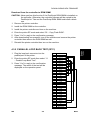
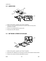
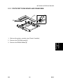
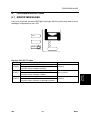
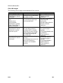
1
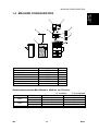
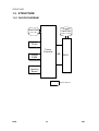
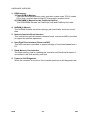
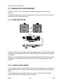
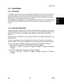
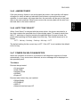
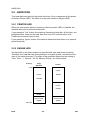
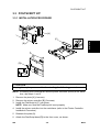
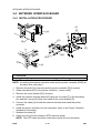
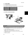
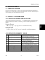
B358 SERVICE MANUAL RICOH GROUP COMPANIES ® ® B358 SERVICE MANUAL RICOH GROUP COMPANIES B358 SERVICE MANUAL It is the reader's responsibility when discussing the information contained within this document to maintain a level of confidentiality that is in the best interest of Ricoh Corporation and its member companies. NO PART OF THIS DOCUMENT MAY BE REPRODUCED IN ANY FASHION AND DISTRIBUTED WITHOUT THE PRIOR PERMISSION OF RICOH CORPORATION. All product names, domain names or product illustrations, including desktop images, used in this document are trademarks, registered trademarks or the property of their respective companies. They are used throughout this book in an informational or editorial fashion only and for the benefit of such companies. No such use, or the use of any trade name, or web site is intended to convey endorsement or other affiliation with Ricoh products. 2000 RICOH Corporation. All rights reserved. WARNING The Service Manual contains information regarding service techniques, procedures, processes and spare parts of office equipment distributed by Ricoh Corporation. Users of this manual should be either service trained or certified by successfully completing a Ricoh Technical Training Program. Untrained and uncertified users utilizing information contained in this service manual to repair or modify Ricoh equipment risk personal injury, damage to property or loss of warranty protection. Ricoh Corporation LEGEND PRODUCT CODE B358 COMPANY GESTETNER RICOH SAVIN Printer Controller Type 450e DOCUMENTATION HISTORY REV. NO. * DATE 3/2000 COMMENTS Original Printing TABLE OF CONTENTS OVERALL INFORMATION 1. OVERALL MACHINE INFORMATION ........................................ 1-1 1.1 INTRODUCTION ...................................................................................... 1-1 1.2 SPECIFICATIONS .................................................................................... 1-2 1.3 SOFTWARE ............................................................................................. 1-2 1.3.1 PRINTER DRIVERS ........................................................................ 1-2 1.3.2 NETWORK UTILITIES..................................................................... 1-2 1.4 MACHINE CONFIGURATION .................................................................. 1-3 1.5 STRUCTURE............................................................................................ 1-4 1.5.1 BLOCK DIAGRAM ........................................................................... 1-4 1.5.2 DESCRIPTIONS .............................................................................. 1-5 DETAILED DESCRIPTIONS 2. DETAILED SECTION DESCRIPTIONS....................................... 2-1 2.1 HARDWARE OVERVIEW ........................................................................ 2-1 2.2 IMAGE PRINTING .................................................................................... 2-3 2.3 IMAGE DATA PROCESSING................................................................... 2-4 2.3.1 EDGE SMOOTHING........................................................................ 2-4 2.3.2 TONER SAVING MODE .................................................................. 2-4 2.4 FEATURES............................................................................................... 2-5 2.4.1 SORTING ........................................................................................ 2-5 2.4.2 DUPLEX PRINTING ........................................................................ 2-5 2.4.3 STAPLING ....................................................................................... 2-6 2.4.4 PUNCHING...................................................................................... 2-6 2.4.5 JAM RECOVERY............................................................................. 2-7 2.4.6 AUTO TRAY SELECT ..................................................................... 2-7 2.4.7 POWER ON SELF DIAGNOSTICS ................................................. 2-7 2.5 HARD DISK .............................................................................................. 2-8 2.5.1 PRINTER HDD ................................................................................ 2-8 2.5.2 ENGINE HDD .................................................................................. 2-8 2.6 PAPER HEIGHT DETECTION ................................................................. 2-9 2.7 PAPER OVERFLOW DETECTION ........................................................ 2-10 2.7.1 STANDARD OUTPUT TRAY ......................................................... 2-10 2.7.2 BRIDGE UNIT................................................................................ 2-10 INSTALLATION 3. INSTALLATION PROCEDURE ................................................... 3-1 3.1 PRINTER CONTROLLER......................................................................... 3-1 3.1.1 ACCESSORY CHECK ..................................................................... 3-1 3.1.2 REQUIRED MAIN MACHINE OPTIONS ......................................... 3-1 i 3.1.3 INSTALLATION PROCEDURE........................................................ 3-2 3.2 HARD DISK .............................................................................................. 3-8 3.2.1 INSTALLATION PROCEDURE........................................................ 3-8 3.3 POSTSCRIPT KIT .................................................................................... 3-9 3.3.1 INSTALLATION PROCEDURE........................................................ 3-9 3.4 NETWORK INTERFACE BOARD .......................................................... 3-10 3.4.1 INSTALLATION PROCEDURE...................................................... 3-10 3.5 DRAM SIMM........................................................................................... 3-11 3.5.1 REQUIRED SPECIFICATION CHECK .......................................... 3-11 3.5.2 INSTALLATION PROCEDURE...................................................... 3-11 3.6 CONNECTING THE INTERFACE CABLES ........................................... 3-12 3.6.1 PARALLEL INTERFACE ............................................................... 3-12 3.6.2 NETWORK INTERFACE ............................................................... 3-12 3.7 CHECKING THE CONNECTIONS ......................................................... 3-12 3.7.1 CONNECTION BETWEEN PRINTER CONTROLLER (AND RELATED OPTIONS; POSTSCRIPT ROM, DRAM SIMM, HARD DISK DRIVE, NIB) AND ENGINE. ..................................... 3-12 3.7.2 CONNECTION BETWEEN MAIN CONTROLLER BOARD AND THE NETWORK INTERFACE BOARD ................................ 3-14 SERVICE TABLES 4. SERVICE TABLE ........................................................................ 4-1 4.1 GENERAL CAUTION................................................................................ 4-1 4.2 SERVICE PROGRAM MODE................................................................... 4-1 4.2.1 SERVICE PROGRAM ACCESS PROCEDURE .............................. 4-1 4.2.2 SERVICE PROGRAM MODE TABLES ........................................... 4-1 4.3 DOWNLOADING NEW FIRMWARE ........................................................ 4-2 4.3.1 FIRMWARE UPDATE USING A FLASH MEMORY CARD (SP02 AND 04) ................................................................................ 4-2 4.3.2 FIRMWARE UPDATE FROM PARALLEL PORT (SP01 AND 03) ................................................................................ 4-3 4.3.3 FORMATTING THE HARD DISK (SP06) ........................................ 4-3 4.3.4 COPY FLASH ROM (SP05)............................................................. 4-4 4.3.5 PARALLEL LOOP BACK TEST (SP11)........................................... 4-5 4.4 USER PROGRAM MODE......................................................................... 4-6 4.4.1 UP MODE TABLE............................................................................ 4-6 4.5 DIP SWITCHES/JUMPER PINS/LEDS..................................................... 4-7 4.5.1 DIP SWITCHES ............................................................................... 4-7 4.5.2 JUMPER PINS................................................................................. 4-7 4.5.3 LEDS ............................................................................................... 4-7 4.6 SPECIAL TOOLS ..................................................................................... 4-7 REPLACEMENT AND ADJUSTMENT 5. REPLACEMENT AND ADJUSTMENT........................................ 5-1 5.1 PRINTER CONTROLLER BOARD........................................................... 5-1 5.2 HARD DISK .............................................................................................. 5-2 ii Rev. 08/2003 5.3 NETWORK INTERFACE BOARD .............................................................5-2 5.3.1 POSTSCRIPT ROM BOARD AND DRAM SIMM .............................5-3 TROUBLESHOOTING 6. TROUBLESHOOTING ................................................................. 6-1 6.1 ERROR MESSAGES ................................................................................6-1 6.2 LEDS .........................................................................................................6-3 6.2.1 LOCATION .......................................................................................6-3 6.2.2 LED CODE TABLE ...........................................................................6-4 iii REPLACEMENT AND ADJUSTMENT B358 TROUBLESHOOTING B358 TAB POSITION 1 TAB POSITION 2 TAB POSITION 3 TAB POSITION 4 TAB POSITION 5 SERVICE TABLES B358 TAB POSITION 6 INSTALLATION B358 TAB POSITION 7 DETAILED DESCRIPTIONS B358 TAB POSITION 8 OVERALL INFORMATION B358 OVERALL INFORMATION 1. OVERALL MACHINE INFORMATION 1.1 INTRODUCTION The A283/A284 base engine contains an interface for the B358 multi-function controller. The B358 multi-function controller adds fax and/or printer functions. Printer and fax functions can operate independently and simultaneously with other functions in the background, and their output will be interleaved with the copy mode output. The printer supports the PCL6, and PostScript level 3. PostScript language support is an optional function. Host printer data can be received via the standard parallel port or the optional Network Interface Board (NIB). The parallel port supports bi-directional Command and Status feed back communication with the host machines. An optional IDE hard disk drive provides font download and other functions. Additional DRAM SIMMs can be installed to boost the printer performance. Images can be rasterized at 300, 400, or 600 dpi in the controller but printed at 400 or 600 dpi. For 300 dpi printing, the 300 dpi data from the controller is simulated in the base engine by printing the same pixel twice and the same line twice at 600 dpi. The A283 engine can print 35 pages per minute at both 400 and 600 dpi. On the other hand, the A284 engine can print 45 pages per minute at both 400 and 600 dpi. SM 1-1 B358 Overall Information INTRODUCTION SPECIFICATIONS 1.2 SPECIFICATIONS Resolution: 600 x 600 dpi 400 x 400 dpi (available when the PostScript option is installed) 300 x 300 dpi (simulated by doubling pixel width and height at 600 dpi resolution) Printing Speed: 35 ppm (A283) 45 ppm (A284) Printing Emulation: Main Controller Board: PCL5e and PCL6 Optional PS Board: Printer Font: PostScript Level 3 45 scaleable typefaces in 14 typeface families (35 Intellifont and 10 TrueType format fonts) 1 bitmapped typeface in the Line Printer typeface family Printer Interface: Bi-directional Parallel x 1 (Standard) Network Interface x 1 (Option) Ethernet (100 base-TX/10 base-T for TCP/IP, IPX/SPX, EtherTalk) DRAM Capacity: 8 MB (Standard) 2 DRAM SIMM slots (up to 64 MB) Maximum Total: Up to 72 MB 1.3 SOFTWARE 1.3.1 PRINTER DRIVERS The following printer drivers are enclosed in the drivers and utilities CD-ROM. • PCL5e Printer Driver for Windows 95/98/2000/NT4.0 • PCL6 Printer Driver for Windows 95/98/2000/NT4.0 • PS3 Printer Driver for Windows 95/98/2000/NT4.0 and Macintosh 1.3.2 NETWORK UTILITIES The network utilities are enclosed in the Network Interface Board option. Refer to the NIB manual for details. B358 1-2 SM MACHINE CONFIGURATION 4 2 Overall Information 1.4 MACHINE CONFIGURATION 5 6 3 7 1 B358V500.WMF Item Printer Controller PostScript Kit Hard Disk Network Interface Board Mailbox Mailbox Bridge Unit RAM SIMM Machine Code B358 A854 A853 A855 G909 G912 --- No. 3 7 4 5 1 2 6 Relationship between Main Machine, Mailbox, and Finisher O: Available Model A283 A284 SM Mailbox Installed Not installed Installed Not installed 1,000 sheet Finisher X O X O 1-3 X: Not available 3,000 sheet Finisher X X O O B358 STRUCTURE 1.5 STRUCTURE 1.5.1 BLOCK DIAGRAM Engine Hard Disk Hard Disk PS Kit Printer Controller DRAM SIMM MB BICU Network Interface Board : Printer's Options B358V501.WMF B358 1-4 SM 1.5.2 DESCRIPTIONS 1. Printer Controller The printer controller handles the following functions: • Printer host interface • Printing functions • Interface and control of additional controller options (HDD, PS kit, DRAM SIMM, and network interface board) 2. Hard Disk (option) This HDD stores the additional soft fonts (both PCL and PS fonts). 3. PS Kit (option) This is to add the PostScript level 3 feature. 4. Network Interface Board (option) The network interface board is an additional printer interface to allow the printer to be used on a network. 5. DRAM SIMM (option) There are two DRAM SIMM slots. This is used for an additional printer processing memory area. 8, 16, or 32 Mbyte standard SIMM modules can be installed. As a result, up to 72 Mbytes of RAM are installable (8 Mbytes on board plus 64 Mbytes of optional SIMM). 6. MB (Mother Board) This connects the controller to the BICU board in the base machine. SM 1-5 B358 Overall Information STRUCTURE DETAILED DESCRIPTIONS HARDWARE OVERVIEW 2. DETAILED SECTION DESCRIPTIONS Flash ROM NVRAM Detailed Descriptions 2.1 HARDWARE OVERVIEW Flash Memory Card I/F ROM & I/O Bus CPU CPU Bus EIDE Disk Interface CoProcessor DRAM Bus NIB Interface DRAM HDD Network Interface Board Printer Controller Mother Board DRAM SIMM DRAM SIMM BICU PC/AT Compatible via Parallel Port B358D500.WMF The above block diagram shows the major components of the printer controller. The main features of the controller are as follows. 1. CPU An IBM PPC603 (100 MHz) processor is used. A 33 MHz oscillator is used as the base clock for both this CPU and the coprocessor. 2. Co-processor This performs the following functions. • ROM control • I/O control • DRAM control • Printer video interface • Printer communication interface • IEEE 1284 compliant bi-directional parallel port interface • Interrupt control SM 2-1 B358 HARDWARE OVERVIEW 3. ROM memory 1) Flash ROM (4 Mbytes) This flash ROM includes boot code, operation system code, PCL5e codes, PCL6 code, and font data for both PCL languages (resident fonts). 2) ROM SIMM (4 Mbytes for the PostScript option) This ROM SIMM includes the PostScript code and PostScript font data. 4. NVRAM (8 Kbytes) This NVRAM contains the printer settings, job record data, and error record data. 5. Network Interface Board Interface This controls the optional network interface board, and printer MIB is provided to support the network operations. 6. Hard Disk Drive Interface (Enhanced IDE) This HDD interface is provided to support storage of fonts downloaded from a PC. 7. Flash Memory Card Interface The flash memory card for updating the controller and PostScript firmware is connected to this flash memory card slot. 8. Power-on Self Diagnostic When the controller is turned on, the controller performs a self diagnostic test. B358 2-2 SM IMAGE PRINTING 2.2 IMAGE PRINTING Parallel Interface, from PC Printer Controller NIB Detailed Descriptions CPU Co-processor Resident RAM DRAM SIMM BICU LD Unit GAVD IPU FCI MSU HDD B358D502.WMF Printer Controller Resident RAM Base Engine BICU MSU HDD IPU LD Co-processor PCL-5e NIB Buffer Parallel Intelligent Personality Selection PCL-6 Image Data Generation Post script DRAM SIMM B358D503.WMF The printer controller receives the print data from the computer through the parallel or network interface port. The co-processor handles the image data but it only makes a raster image. All image processing, such as edge smoothing and toner saving, are done in the base engine. The image data from a PC goes to the buffer in the resident RAM. Then, it goes to the co-processor. The co-processor selects the printer language automatically, then the co-processor generates the print data to match the selected printer language. After generating the print data, the co-processor sends it to the LD unit through the IPU on the BICU board. At that time, the data is also sent to the hard disk for multiple printing and sorting, as well as backup in case of paper jams. SM 2-3 B358 IMAGE DATA PROCESSING 2.3 IMAGE DATA PROCESSING The FCI in the LD unit is responsible for edge smoothing and toner saving functions. The edge smoothing and toner saving modes can be switched on or off using the printer user tool or the printer driver. 2.3.1 EDGE SMOOTHING B358D504.WMF Usually, binary picture processing generates jagged edge on characters as shown in the above left illustration. The FCI reduces the edges of characters using edge smoothing. Whether or not the object pixel undergoes smoothing depends on the surrounding image data. Smoothing for the object pixel is done by changing the laser pulse position. 2.3.2 TONER SAVING MODE Toner saving is done by reducing the number of black dots printed, not by varying the development bias. In toner saving mode, the image data is filtered through a matrix. As a result of passing through the filter, less toner is used to create the latent image on the drum, and black areas print as gray. B358 2-4 SM FEATURES 2.4 FEATURES If “Collate” is turned on and a multicopy job is printed, the first copy of the job will be printed directly. At the same time, the image data for the copy job is stored in the hard disk of the main machine. When the main machine prints the next copy, the next copy will be printed from the hard disk. If the finisher is not installed, the rotate sort feature can be used. The MSU block in the BICU board rotates the image, in the same way as image rotation for the copier. 2.4.2 DUPLEX PRINTING Duplex printing is available with all output bin options but not all paper sizes (refer to the specifications section of the copier manual). If a job specifies duplex but the paper size to be used is not usable in the duplex unit, the job will be printed simplex. Duplex printing is available in two binding methods: Short-edge binding and Longedge binding. In short-edge binding, when printing the second side of a page, the image may require rotation. The image is rotated by the co-processor in the printer controller. The co-processor corrects the image printing order for duplexing as follows. • Larger than A4 lengthwise/LT lengthwise (example 8 pages) 2nd page – 1st page – 4th page – 3rd page – 6th page – 5th page – 8th page – 7th page • Up to A4 lengthwise/LT lengthwise (example 8 pages) 2nd page – 4th page – 1st page – 6th page – 3rd page – 8th page – 5th page – 7th page SM 2-5 B358 Detailed Descriptions 2.4.1 SORTING FEATURES 2.4.3 STAPLING Stapling is only available when the 3,000-sheet finisher or 1,000-sheet finisher is installed. The finishers have the following stapling positions. 1) Upper left, diagonal 2) Upper right, diagonal 3) Left, two staples 4) Top, two staples 5) Right, two staples 6) Upper left, horizontal 7) Upper right, horizontal 8) Upper left, vertical 9) Upper right, vertical NOTE: With the 1,000-sheet finisher, only stapling positions 1) and 2) are available. Depending on the paper orientation, the image may have to be rotated. This image rotation is done by the co-processor in the printer controller. There is a limit for the number of sheets which can be stapled by each finisher. If a job that specifies stapling has more than this number of sheets, it will not be stapled. 2.4.4 PUNCHING Punching is only available when the punch unit is installed with the 3,000-sheet finisher. The number of holes depends on the type of punching unit. The punching unit has only one available position, so the relationship between the punching position and the printed image depends on the paper feeding orientation and imaging. The punching positions are defined as follows. 1) Left 2) Top 3) Right B358 2-6 SM FEATURES If the jam recovery feature is on and a paper jam occurs, the controller will reprint all pages for which a feed-out indication has not been received from the main machine. In usual cases, all image data from the controller will be sent to the hard disk on the main machine, When a jam occurs, the recovery data will be sent from the hard disk on the main machine. 2.4.6 AUTO TRAY SELECT When “Auto Select” is selected with the printer driver, the printer searches for a tray that contains the specified size of normal plain paper. The search starts from the LCT, and when a tray that contains the specified size of paper is found, the printer starts printing and feeds paper from that tray. The search sequence is as follows. LCT – 1st tray – 2nd tray – 3rd tray – 4th tray – LCT The default setting for the current tray is LCT. If the LCT is not installed, the default is the 1st tray. 2.4.7 POWER ON SELF DIAGNOSTICS When the controller is turned on, it performs a self diagnostic sequence of tests automatically. If any errors were detected, an error message will be displayed on the operation panel. Test Items Devices always tested • Co-processor • Flash ROM • Resident RAM • NVRAM • Engine I/F Devices tested when they are installed • DRAM SIMM • PS DIMM I/F • HDD I/F • Network interface board I/F SM 2-7 B358 Detailed Descriptions 2.4.5 JAM RECOVERY HARD DISK 2.5 HARD DISK Two hard disks are used for the printer functions. One is connected to the printer controller (Printer HDD). The other is in the main machine (Engine HDD). 2.5.1 PRINTER HDD When the main power switch is turned on after the printer HDD is installed, the machine asks you to format the hard disk. If you press the “Yes” button, the machine formats the hard disk. At this time, two partitions will be made on the hard disk. One is for PCL and the other is for PostScript (fonts and macros only). If you press the “Ignore” button, the machine determines that there is no optional printer hard disk. 2.5.2 ENGINE HDD The hard disk in the main machine is used for both copy and printer functions. Therefore, the hard disk has three partitions: for copier, printer, and archive files (one of the copier features). The sizes of the partitions depend on the setting of “User Tools – 1. System – No.23, Memory Priority”, as shown below. Priority: 0 MB Copy (Default) Printer Copier 720MB Copier 1200MB Printer 612MB Printer 132MB Archive Files 308MB Archive Files 308MB 1640 MB B358D505.WMF B358 2-8 SM PAPER HEIGHT DETECTION 2.6 PAPER HEIGHT DETECTION When the amount of paper decreases, the bottom plate pressure lever [C] moves up and the actuator [D] which is mounted on the same drive shaft as the pressure lever rotates. [B] [A] [D] 34 33 11 35 [C] The following combination of sensor signals is sent to the printer controller. Amount of Paper Full Near Full Near End 1 Near End 2 Paper Height Sensor [A] OFF ON ON OFF Paper Height Sensor [B] ON ON OFF OFF 34 33 11 35 34 33 11 35 36 34 33 11 35 B358D506.WMF SM 2-9 B358 Detailed Descriptions The amount of paper in the tray is detected by the combination of two paper height sensors [A] and [B]. PAPER OVERFLOW DETECTION 2.7 PAPER OVERFLOW DETECTION 2.7.1 STANDARD OUTPUT TRAY [B] [A] B358D507.WMF The standard output tray can stack about 500-sheets. There is a paper limit sensor [A] to prevent paper overflow. When the tray is full, the paper stack pushes up the feeler [B] then the paper limit sensor is activated. When the sensor stays activated for a certain time, the machine determines that the standard tray is full. The machine stops the print job until the paper limit sensor is deactivated. 2.7.2 BRIDGE UNIT [A] B358D508.WMF The bridge unit has a paper sensor [A] to detect paper on the bridge unit. This is monitored to ensure that the bridge unit does not contain more than 250-sheets. If a print job of more than 250-sheets is executed, the machine will print up to 250 pages, then the print job is stopped. Once the output stack is removed, the printing job automatically continues. B358 2-10 SM INSTALLATION PRINTER CONTROLLER 3. INSTALLATION PROCEDURE 3.1 PRINTER CONTROLLER 3.1.1 ACCESSORY CHECK Check the accessories in the box against the following list. Description Q’ty 1 4 2 4 2 1 1 1 2 1 2 1 Cable Paper Height Sensor Edge Clamp Cable Clamp Paper Height Sensor Feeler Paper Sensor Key Top - Copy/Printer Paper Limit Sensor Unit Tapping Screw - M3 x 8 Pan Head Screw – M3 x 8 Tapping Screw - M3 x 6 Installation Procedure Installation No. 1 2 3 4 5 6 7 8 9 10 11 12 3.1.2 REQUIRED MAIN MACHINE OPTIONS Please note that it is necessary to first install the Expansion Box Type 450e (A872). SM 3-1 B358 PRINTER CONTROLLER 3.1.3 INSTALLATION PROCEDURE [D] [E] [C] [A] [B] B358I503.WMF B358I502.WMF [I] [J] [F] [H] [G] B358I500.WMF B358I507.WMF !CAUTION Unplug the main machine power cord before starting the following procedure. Expansion Box Installation NOTE: If either the Scanner Option Type 450e or Fax Option Type 450e has been installed, skip steps 1 through 8. 1. Remove the connector cover [A], rear cover [B] (4 screws), and left cover [C] (4 screws). 2. Remove the cutout [D] in the left cover. 3. Remove the HDD [E] (4 screws, 2 connectors). 4. Remove the bracket [F] (1 screw). 5. Remove the two plates [G] (2 screws) and [H] (4 screws). 6. Connect the cable [I] to the expansion box [J] and install the expansion box (4 screws). 7. Reinstall the HDD. 8. Reinstall the left, rear, and connector covers. B358 3-2 SM PRINTER CONTROLLER Printer Controller Installation NOTE: 1) The optional HDD (A853), PS Kit (A854) or Network Interface Board (A855) must be installed before installing the printer controller in the machine. Refer to each installation manual for more detail. 2) If either the Scanner Option Type 450e or Fax Option Type 450e has been installed, perform step 9. If neither have been installed, skip step 9. 9. Remove the two plates (2 screws) [A] and [B] (4 screws). 10. After installing the additional options on the printer controller, install the controller [C] in the left-most slot of the expansion box [D] (2 screws). Installation 11. Reattach plate [B]. [B] [D] [C] SM 3-3 [A] B358 PRINTER CONTROLLER [A] [B] B358I510.WMF [H] [C] B358I511.WMF [D] [E] [F] [L] [L] [I] [L] [K] [G] [J] [F] [E] [L] B358I512.WMF [K] B358I513.WMF Paper Height Sensor Installation 12. Remove the connector covers [A] and lower rear cover [B] (4 screws, 3 connectors). 13. Pull out the two paper trays [C]. 14. Install edge clamps [D] in both openings [E]. 15. Connect the four paper height sensors [F] to the cable [G]. 16. Connect the cable to CN234 of the PCB [H]. 17. Pass the two sensors attached to the white connector [I] through the upper opening. Pass the other two sensors attached to the red connector [J] through the lower opening. Secure the cables in place with the edge clamps attached in step 14. 18. Install the four paper height sensors [K] from the front side of the machine, as shown. 19. Install the four cable clamps [L], then clamp the cables. B358 3-4 SM PRINTER CONTROLLER [B] [D] [A] [E] Installation B358I514.WMF [F] [C] B358I515.WMF [G] B358I516.WMF 20. Install the paper height sensor actuator [A] on the bottom plate shaft [B] of each paper tray. 21. Reassemble the machine. Paper Limit Sensor and Paper Sensor Installation If the optional bridge unit has been installed, skip steps 22 and 23. 22. Peel off the black tape [C] from the anti-static brush [D], then pull out the cable [E]. 23. Connect the cable to the sensor [F], then install the paper limit sensor unit [G] (2 screws). SM 3-5 B358 PRINTER CONTROLLER [A] [F] [E] [D] [C] [B] B358I518.WMF [H] [G] Copy B358I517.WMF Printer B358I501.WMF Perform steps 24 to 26 only if the optional bridge unit has been installed. If it has not been installed, go on to step 27. 24. Remove the connector cover [A] and bridge unit [B] (2 screws, 2 connectors). 25. Open the right cover [C] of the bridge unit and peel off the black tape [D], then pull out the connector [E]. 26. Install the paper sensor [F] (1 screw, 1 connector) and reinstall the bridge unit. 27. Remove the bottom cap [G] of the operation panel. NOTE: If both the Scanner Option Type 450e and Fax Option Type 450e have not been installed, remove the top cap of the operation panel as well. 28. Install the Printer key [H] on the operation panel as shown. NOTE: If both the Scanner Option Type 450e and Fax Option Type 450e have not been installed, install the Copy key on the operation panel as well (see the illustration). B358 3-6 SM PRINTER CONTROLLER 29. Make sure that the parallel cable is not connected to the controller. Turn the machine on and check the setting of the following copier SP mode: • SP5-907: Plug & Play Brand Name and Production Name Setting – select the correct one. 30. If the customer wishes to expand the hard disk space in the mainframe for use by the printer, change the setting of “Memory Priority” (User Tool – 1. System – No.23) to “Printer”. 31. Print the Printer Configuration Page (User Tool – 4. Printer – 7. List Print – 5. Configuration Page) to check the printer controller connection. Installation 32. If the parallel cable is going to be connected, first turn off the machine. After connecting the cable, turn the machine back on. SM 3-7 B358 HARD DISK 3.2 HARD DISK 3.2.1 INSTALLATION PROCEDURE [A] [D] [E] [C] [B] A853I553.WMF [C] A853I506.WMF !CAUTION Unplug the copier power cord before starting the following procedure. NOTE: If installing this hard disk drive and the printer controller (B358) at the same time, skip steps 1 and 2. 1. Remove the plate [A] (4 screws). 2. Remove the printer controller [B] (2 screws). 3. Attach the HDD brackets [C] to the hard disk drive [D] as shown (2 screws each). 4. Connect the cable [E] to the hard disk drive. 5. Attach the hard disk drive to the printer controller (4 screws, 1 connector). 6. Install the printer controller into the mainframe (refer to the Printer Controller Installation Procedure). 7. Reattach the plate [A]. 8. After turning on the main switch and pressing the printer key, you will be prompted to format the disk drive. Press the " key twice to format the disk. 9. After formatting the hard disk, turn the main switch off and on. B358 3-8 SM POSTSCRIPT KIT 3.3 POSTSCRIPT KIT 3.3.1 INSTALLATION PROCEDURE [A] Installation [C] [B] A854I503.WMF A854I550.WMF [D] A854I501.WMF !CAUTION Unplug the copier power cord before starting the following procedure. NOTE: If installing this PostScript Kit and the printer controller (B358) at the same time, skip steps 1 and 2. 1. Remove the plate [A] (4 screws). 2. Remove the printer controller [B] (2 screws). 3. Install the PostScript kit [C], as shown. NOTE: Make sure that the PostScript kit is set properly. 4. Install the printer controller into the mainframe (refer to the Printer Controller Installation Procedure). 5. Reattach the plate [A]. 6. Attach the PostScript decal [D] to the front cover, as shown. SM 3-9 B358 NETWORK INTERFACE BOARD 3.4 NETWORK INTERFACE BOARD 3.4.1 INSTALLATION PROCEDURE [F] [A] [C] [D] [B] A855I553.WMF [H] [G] [E] A855I551.WMF [I] A855I504.WMF !CAUTION Unplug the copier power cord before starting the following procedure. NOTE: If installing this network interface board and the printer controller (B358) at the same time, skip step 1. 1. Remove the plate [A] (4 screws) and the printer controller [B] (2 screws). 2. Attach two spacers [C] to the printer controller (1 screw each). 3. Remove the cover bracket [D] (2 screws). 4. Install the network interface board [E] using the 2 screws [F] in the accessory box and the 2 screws [G] that were used for the cover bracket [D]. 5. Connect the cable [H] to both the network interface board and the printer controller. 6. Install the printer controller into the mainframe (refer to the Printer Controller Installation Procedure). 7. Reattach the plate [A]. 8. Attach the core [I] to the network (STP) cable as shown. NOTE: The STP cable should be coiled twice inside the core as shown. B358 3-10 SM DRAM SIMM 3.5 DRAM SIMM 3.5.1 REQUIRED SPECIFICATION CHECK Before installing the DRAM SIMM, check that it satisfies the requirements below. PC Compatible 72 pins 70 ns or faster 8, 16, or 32 MB Any OK Installation Type Number of bins Access speed Capacity Parity 3.5.2 INSTALLATION PROCEDURE [A] [C] [B] B358I553.WMF B358I593.WMF !CAUTION Unplug the copier power cord before starting the following procedure. NOTE: If installing this DRAM SIMM and the printer controller (B358) at the same time, skip step 1. 1. Remove the plate [A] (4 screws) and the printer controller [B] (2 screws). 2. Install the DRAM SIMM [C], as shown. NOTE: Make sure that the DRAM SIMM is installed properly. 3. Install the printer controller in the mainframe (refer to the Printer Controller Installation Procedure). 4. Reattach the plate [A]. SM 3-11 B358 CONNECTING THE INTERFACE CABLES 3.6 CONNECTING THE INTERFACE CABLES 3.6.1 PARALLEL INTERFACE An IEEE1284 compatible printer cable is required to connect the printer controller to a host PC parallel port. 3.6.2 NETWORK INTERFACE An STP (Shielded Twisted Pair) cable with RJ45 connectors is required to connect the Network Interface Board to the computer network. (The cable should be Category/Type 5 or better.) After hardware setup, the network setup should be done by the user. The setup procedure is described in the NIB manual. 3.7 CHECKING THE CONNECTIONS 3.7.1 CONNECTION BETWEEN PRINTER CONTROLLER (and related options; PostScript ROM, DRAM SIMM, Hard Disk Drive, NIB) AND ENGINE. 1. Plug in the power cord and turn on the main and operation switches. 2. Enter the printer user mode. 1) Press the User Tool key. 2) Press 4 using the ten-key pad. 3. Print out the printer configuration page. 1) Press the Next button then press 7 using the ten-key pad to select List Printing. 2) Press the Next button then press 5 using the ten-key pad to print the configuration page. The machine prints the printer configuration page automatically. NOTE: For more detailed information about the operation panel settings, refer to the operation manual. The printer configuration page is similar to that shown on the next page. B358 3-12 SM CHECKING THE CONNECTIONS CONFIGURATION MENU RESOLUTION = 600 AUTO CONTINUE = OFF EDGE SMOOTHING = ON AUTOCONT.TIMEOUT = 10 Printer Configuration Page POSTSCRIPT MENU PRINT ERRORS = OFF FEEDER MENU PAGE SIZE = LETTER TRAY PRIORITY = AUTO AUTO TRAY SWITCH = ON BYPASS PAPER TYPE = NORMAL DUPLEX = OFF BINDING = LONG SORT = OFF STAPLE = OFF PUNCH = OFF NETWORK MENU I/O TIMEOUT = 30 TCP/IP SETTING: IP ADDRESS = 131.100.100.111 SUBNET MASK = 255.255.255.0 GATEWAY ADDRESS = 131.100.100.1 PARALLEL MENU EMULATION = AUTO BIDIRECTION = ON I/O TIMOUT = 30 CONFIGURATION MENU RESOLUTION = 600 AUTO CONTINUE = ON EDGE SMOOTHING = ON AUTOCONT. TIMEOUT = 10 NETWORK MENU I/O TIMEOUT = 30 TCP/IP SETTING: IP ADDRESS = 131.100.100.111 SUBNET MASK = 255.255.255.0 GATEWAY ADDRESS = 131.100.100.1 PRINTER DETAILS MODEL: MANUFACTURER: MACHINE S/N: 00000010200 SERVICE PHONE: 00-0000-0000 FIRMWARE LEVELS: Controller 1.84e Emulation Language of PCL5e V 1.4.10 98/05/06 Emulation Language of PCL6 V 1.1.10 98/05/06 PS 1.18 [D] PRINTER DETAILS MODEL: MANUFACTURER: MACHINE S/N: 00000010200 SERVICE PHONE: 00-0000-0000 FIRMWARE LEVELS: Controller 1.84e Emulation Language of PCL5e V 1.4.10 98/05/06 Emulation Language of PCL6 V 1.1.10 98/05/06 PS 1.18 PRINTER OPTIONS Printer Hard Disk Drive Adobe Postscript Network Interface Board PAPER HANDLING OPTIONS: MSU Installed Standard Tray 1 Standard Tray 2 Standard Tray 3 Standard Tray 4 Manual Paper Tray Large Capacity Tray Duplex Unit 9 Bin Mailbox Unit Finisher 3000 Multi-Function Inner Tray Punch Unit, 2 Hole PRINTER OPTIONS: Printer Hard Disk Drive Adobe Postscript Network Interface Board PAPER HANDLING OPTIONS: MSU Installed Standard Tray 1 Standard Tray 2 Standard Tray 3 Standard Tray 4 Manual Paper Tray Large Capacity Tray Duplex Unit 9 Bin Mailbox Unit Finisher 3000 Multi-Function Inner Tray Punch Unit, 2 Hole TOTAL MEMORY = 72 MB PCL, PCL5e and PCL6 are trademarks of Hewlett- Packard Corporation. Adobe, PostScript, the Adobe logo and the Postscript logo are the trademarks of Adobe Systems Incorporated. [A] [B] TOTAL MEMORY = 72 MB B358I504.WMF B358I505.WMF Check the following: • For the printer controller board, confirm that the machine prints the printer configuration page. • For the hard disk drive and PS kit, confirm that the configuration page includes them in the “Printer Options” section [A]. • For DRAM SIMM, confirm that “Total Memory” [B] printed on the configuration page shows the correct amount of memory in the machine (including the 8 MB on board and the SIMM). • For the NIB, confirm that the configuration page includes the “Network Menu” section [C] and includes the network interface board in the “Printer Options” section [A]. • For the firmware version, check “Firmware Levels” [D]. If any problem occurs with the above checks, reinstall the printer controller and other options. Then set up the machine again and redo the test. SM 3-13 B358 Installation PCL MENU ORIENTATION = PORTRAIT FORM LENGTH = 60 LINES FONT SOURCE = INTERNAL FONT NUMBER = 0 POINT SIZE = 12.00 FONT PITCH = 10.00 SYMBOL SET = ROMAN-8 [C] CHECKING THE CONNECTIONS 3.7.2 CONNECTION BETWEEN MAIN CONTROLLER BOARD AND THE NETWORK INTERFACE BOARD There are two ways to check the connection between the main controller board and the network interface board. 1. Check “Network Menu” on the configuration page. 2. Check the Network Interface Board Status Sheet with the network information that is printed automatically after power on. Printing the Network Interface Board Status Sheet Whenever the main switch is turned on, the machine prints the network interface board status sheet automatically. NOTE: If the machine does not print the status sheet, check the Network menu in the printer user tools. If any problem occurs with the above check, reinstall the printer controller and other options. Then set up the machine again and redo the test. B358 3-14 SM SERVICE TABLES GENERAL CAUTION 4. SERVICE TABLE 4.1 GENERAL CAUTION Do not turn off the machine or switch the controller off-line when the data LED is blinking or is lit, or the data which has been sent to the controller will be lost. If you need to do this, ask the customer for consent. 4.2 SERVICE PROGRAM MODE 4.2.1 SERVICE PROGRAM ACCESS PROCEDURE The service program access procedure, such as “Entering Service Program (SP) Mode” and “Exiting SP Mode” is the same procedure as for copier and fax, as follows. Entering SP mode Service Tables ! → " → # → $ → % (hold it for more than 3 seconds.) Exiting SP mode Press the “Back” and “Exit” keys until the standby mode display appears. 4.1.2 SERVICE PROGRAM MODE TABLES No. 01 02 03 04 05 06 07 08 09 10 11 SM Description Flash System From Parallel Flash System From PCMCIA Flash Postscript From Parallel Flash Postscript From PCMCIA Copy Flash ROM Format Disk Print Job Log Data Print Error Log Data Clear Job Log Counter Clear Error Log Data Parallel Loop Back Test Function Downloads the printer controller firmware from a PC through the parallel port. Downloads the printer controller firmware using an IC card through the PCMCIA port. Downloads the PostScript firmware from a PC through the parallel port. Downloads the PostScript firmware using an IC card through the PCMCIA port. Copies the printer controller firmware between ROM DIMM and printer controller Formats the hard disk drive Prints the print/job count log page Prints the printer error log page Clears the print/job counter Clears the error log counter Performs the parallel loop back test 4-1 B358 DOWNLOADING NEW FIRMWARE 4.3 DOWNLOADING NEW FIRMWARE New firmware for the printer controller and PostScript can be downloaded from a PC through the parallel cable and from a flash memory card through the PCMCIA port. 4.3.1 FIRMWARE UPDATE USING A FLASH MEMORY CARD (SP02 AND 04) 1. Prepare a flash memory card that has been programmed with the latest firmware. NOTE: When you program a flash memory card with a firmware file, use the following parameter settings. • Start Address – 000000h • Length – 3FFFFFh 2. Turn off the machine, remove the cover [A], and insert the flash memory card [B] into the slot so that the “A” side of the card faces the front of the machine. [A] A [B] B358M501.WMF 3. Turn on the machine and enter the printer SP mode. 4. Choose “02 – Flash System From PCMCIA” or “04 – Flash Postscript From PCMCIA” depending on the firmware type. 5. Press “Yes” in reply to the confirmation message. Firmware download will take several minutes. 6. After new firmware has been downloaded successfully, turn off the machine, remove the card from the slot, and turn the machine back on. 7. Print the “Printer Configuration Page” to check the new firmware version ([User Tools] – [4. Printer] – [7. List Print] – [5. Configuration Page]). The firmware version number is printed in the “Printer Details” section of the configuration page. B358 4-2 SM DOWNLOADING NEW FIRMWARE 4.3.2 FIRMWARE UPDATE FROM PARALLEL PORT (SP01 AND 03) 1. Prepare the latest firmware file and Fcopy.exe on a host computer. 2. Turn off the machine, connect the host computer using a parallel cable, and turn the machine back on. 3. Enter the printer SP mode. 4. Choose “01 – Flash System from Parallel” or “03 – Flash Postscript From Parallel” depending on the firmware type. 5. Press “Yes” in reply to the confirmation message. 6. On the host computer, start MS-DOS Prompt and type the following command. Either C:\> FCOPY path\filename CAUTION: Do not turn off the machine while “Downloading New System Software” is displayed on the LCD, even if FCOPY has finished in the MS-DOS Prompt. 7. After new firmware has been downloaded successfully, turn off the machine, disconnect the printer cable if necessary, and turn the machine back on. 8. Print the “Printer Configuration Page” to check the new firmware version ([User Tools] – [4. Printer] – [7. List Print] – [5. Configuration Page]). The firmware version number is printed in the “Printer Details” section of the configuration page. 4.3.3 FORMATTING THE HARD DISK (SP06) This function is used to format the printer hard disk. If the hard disk is formatted, the stored data (downloaded fonts and macros) will be erased. So, when performing this function, ask the customer for consent. After this operation, advise the customer to restore their data, if necessary. 1. Enter the printer SP mode. 2. Choose “06 – Format Disk”. 3. Press “Yes” in reply to the confirmation message. Hard disk formatting will take several minutes. 4. After confirming that formatting was successful, turn the machine off and back on again. SM 4-3 B358 Service Tables or C:\> COPY /b path\filename port DOWNLOADING NEW FIRMWARE 4.3.4 COPY FLASH ROM (SP05) There are two functions; one is to copy the printer controller firmware from the ROM DIMM to the printer controller, the other is the opposite way. Download from ROM SIMM to printer controller When downloading the printer controller firmware from either the flash memory card or a PC was not successful and the printer controller does not start up, the controller firmware cannot be downloaded from the flash memory card or a PC to recover the machine. However, the firmware can be downloaded from ROM SIMM using this function, using the following procedure. [A] CS0 CS0 CS1 CS1 TB1 TB1 TB1 TB1 CS1 CS1 CS0 CS0 TB1 IC10 TB2 IC41 Printer Controller IC9 TB1 CN1 [B] ROM SIMM B358M500.WMF 1. Remove the printer controller. 2. Change the position of the TB1 jumper [A] on the controller from CS0 to CS1. 3. Change the position of the TB1 jumper [B] on the ROM DIMM that contains the controller firmware from CS1 to CS0. 4. Install the ROM SIMM on the controller. CAUTION: Make sure to install the correct ROM SIMM in the PostScript SIMM. 5. Install the printer controller and turn on the machine. 6. Enter the printer SP mode and select “05 – Copy Flash ROM”. 7. Press “Yes” in reply to the confirmation message. 8. After downloading is successful, turn off the machine and remove the printer controller then remove the ROM SIMM as well. 9. Reposition the jumpers on the printer controller and ROM SIMM. 10. Reinstall the printer controller then turn on the machine. 11. Check that the printer controller starts up. B358 4-4 SM DOWNLOADING NEW FIRMWARE Download from the controller to ROM SIMM CAUTION: Never perform this function if the PostScript ROM SIMM is installed on the controller. Otherwise, the controller firmware will be copied to the PostScript kit. Take out the PostScript ROM SIMM and install a blank one. 1. Remove the printer controller. 2. Install the ROM SIMM on the controller. 3. Install the printer controller and turn on the machine. 4. Enter the printer SP mode and select “05 – Copy Flash ROM”. 5. Press “Yes” in reply to the confirmation message. 6. After downloading is successful, turn off the machine and remove the printer controller then remove the ROM SIMM as well. 7. Reinstall the printer controller then turn on the machine. 1. Plug the loop back connector into the parallel port of the printer. 2. Enter the printer SP mode then select “11 – Parallel Loop Back Test”. 3. Press “Yes” in reply to the confirmation message. The result of the test will be displayed on the operation panel. Pin No. 1 2 Signal Name /STROBE DATA_1 3 4 5 DATA_2 DATA_3 DATA_4 6 7 8 9 10 11 12 13 14 DATA_5 DATA_6 DATA_7 DATA_8 /ACK BUSY PE SELECT /AUTOFD 15 16 17 18 19 20 21 22 23 24 25 26 27 28 29 30 31 32 33 34 35 36 NC GND GND PLH GND GND GND GND GND GND GND GND GND GND GND GND /INIT /FAULT NC NC NC /SELECTION Service Tables 4.3.5 PARALLEL LOOP BACK TEST (SP11) B358M502.WMF SM 4-5 B358 USER PROGRAM MODE 4.4 USER PROGRAM MODE A user program (UP) mode is available for printer features as well as for copy and fax. Press the User Tools button to access it. 4.4.1 UP MODE TABLE NOTE: The function of each UP mode is explained in the Printer Reference section of the operating instructions. 1. PCL 2. Postscript 3. Paper Feed 1. Orientation 2. Form Lines 3. Font Source 4. Font Number 5. Point Size 6. Font Pitch 7. Symbol Set 1. Print Errors 1. Input 2. Output 4. Parallel 5. Network 6. Configuration 7. List Print 8. Reset Select B358 1. Paper Size 2. Tray Priority 3. Auto Tray Switch 4. Bypass Paper Type 1. Duplex 2. Sort 3. Staple 4. Punch 1. Emulation 2. Bi-direction 3. I/O Timeout 1. I/O Timeout 2. TCP/IP Menu 1. Resolution 2. Auto Continue 3. Edge Smoothing 4. Autocont. Timeout 1. PS Font List 2. PCL Font List 3. PS Demo Page 4. PCL Demo Page 5. Configuration Page 1. Job Reset 2. Menu Reset 3. System Reset 4-6 SM DIP SWITCHES/JUMPER PINS/LEDS 4.5 DIP SWITCHES/JUMPER PINS/LEDS 4.5.1 DIP SWITCHES SW2: No. 1 2 3 4 Function Destination for firmware downloading Not used On To flash ROM OFF To ROM SIMM Do not change this setting. Keep these both off. Operation mode Normal operation Programming firmware NOTE: The functions of DIP switches no.1 is enabled when changing the setting of no.4 to the off position. However, do not change the default settings. Always do the firmware downloading using SP mode. TB1: Function Bank setting for resident flash ROM CS0 Bank setting for flash ROM is “0”. CS1 Bank setting for flash ROM is “1”. TB2: Function Not used UN-PROT PROT Do not change this setting. Keep at “UN-PROT”. 4.5.3 LEDS Symbol PWR LED2 LED3 LED4 LED5 Function This LED turns on when +5 V is supplied to the printer controller. Refer to section 6.2 (LEDs) for more detail. 4.6 SPECIAL TOOLS Part Number A8545120 G0219350 SM Description ROM SIMM Loop Back Connector 4-7 Q‘ty 1 1 B358 Service Tables 4.5.2 JUMPER PINS REPLACEMENT AND ADJUSTMENT PRINTER CONTROLLER BOARD 5. REPLACEMENT AND ADJUSTMENT !CAUTION Turn off the main power switch and unplug the machine before attempting any of the procedures in this section. 5.1 PRINTER CONTROLLER BOARD [A] [C] [B] Replacement and Adjustment B358R553.WMF B358R506.WMF 1. Remove the printer cables from the printer controller. 2. Remove the plate [A] (4 screws). 3. Slide out the printer controller board [B] (2 screws). 4. Remove the optional hard disk, network interface board, PS kit, and DRAM SIMMs if they are installed (see their replacement procedures). 5. Remove the NVRAM [C] from the old printer controller and install it on the new printer controller. 6. Install the options on the new printer controller. 7. Reattach the plate [A]. SM 5-1 B358 HARD DISK 5.2 HARD DISK [B] [A] [C] B358R504.WMF 1. Slide out the printer controller (see Printer Controller). 2. Dismount the hard disk [A] with bracket and IDE cable from the printer controller (4 screws). 3. Remove two brackets [B] (2 screws each). 4. Disconnect the IDE cable [C]. 5.3 NETWORK INTERFACE BOARD [A] [B] B358R503.WMF 1. Slide out the printer controller (see Printer Controller). 2. Disconnect the cable [A] from the printer controller and network interface board. 3. Remove the network interface board [B] (4 screws). B358 5-2 SM NETWORK INTERFACE BOARD 5.3.1 POSTSCRIPT ROM BOARD AND DRAM SIMM [A] [B] B358R505.WMF 1. Slide out the printer controller (see Printer Controller). 2. Remove the PS ROM board [A]. SM Replacement and Adjustment 3. Remove the DRAM SIMMs [B]. 5-3 B358 TROUBLESHOOTING ERROR MESSAGES 6. TROUBLESHOOTING 6.1 ERROR MESSAGES If an error occurred, the error LED lights (red light with the printer key) and an error message is displayed on the LCD. Copy Printer B358T501.WMF Service Call (SC) Codes SC2000 SC2001 SC2002 SM Description / Definition Functional problems (Self diagnostic error) A diagnostic error occurred at power on. The controller has a hardware problem. Functional problems (Debug trap error) An error has occurred in the controller. The controller has a software problem. Functional problems (Exception error) An error has occurred in the controller. The controller has a software or hardware problem. 6-1 Possible Cause Printer controller board defective. The controller software has a problem. Printer controller board defective. B358 Troubleshooting SC No. ERROR MESSAGES Other Messages The following errors might need assistance from service. Error Message Printer HDD Error. Press Reset to cancel current job. Parallel Communication Error. Please set up communication parameters in parallel menu. Press Reset to cancel current job. Print overrun. Press Reset to cancel current job, or press Continue to print. Memory overflow. Press Reset to cancel current job. B358 Condition A hard disk error was detected during downloading the macro or fonts. Parallel communication error occurred during a print job via the parallel port. • • • • • This error occurred when a file was being printed in banding mode. A complex page may not have enough time to image a band while the engine is printing the previous page. This error occurred during printing. The language has sent a file that is too complex to interpret in the available memory. 6-2 Possible Cause Printer HDD defective Printer controller defective An item in the parallel menu was set incorrectly Parallel cable defective Printer controller defective • Insufficient memory • A complex page is printed • The DRAM SIMM board is defective • The controller is defective • Insufficient memory • A complex page is printed • The DRAM SIMM is board defective • The controller is defective SM LEDS 6.2 LEDS 6.2.1 LOCATION Four LEDs (LED2 to LED5) are located near SW2 on the printer controller. They indicate display the progress of the self test, and errors and status conditions. LED5 LED4 LED3 LED2 PWR TB2 SW2 B358T500.WMF 6.2.2 LED CODE TABLE Self Diagnostic The following LED table is for the self diagnostic function. When an error occurs during the self diagnostic test, all four LEDs blink then indicate the error as shown in the following table. All LEDs on (1 s) → off (1 s) → on (1 s) → off (1 s) → LED4 on (5 s) → from the beginning. 1 = LED is lit, 0 = LED is off LED2 0 0 0 0 0 LEDs LED3 LED4 0 0 0 1 0 1 1 0 1 1 LED5 1 0 1 1 0 Description ROM error RAM (resident, SIMM) error: note 1) NVRAM error: note 1) Fatal error Debug trap error: note 2) NOTE: 1) SC2000 is also displayed. 2) SC2002 is also displayed. SM 6-3 B358 Troubleshooting e.g.) RAM error: LEDS Controller Firmware Copy/Download During controller firmware copying and downloading, the following LED status will be indicated. 1 = LED is lit, 0 = LED is off, 1/0 = LED is blinking LED2 1 0 1/0 0 1 1 1 1 1 1 B358 LEDs LED3 LED4 0 0 1/0 0 1/0 1 0 0 0 0 0 1 0 1 1 0 1 0 1 1 LED5 0 0 0 1 1 0 1 0 1 1 Description Data downloading Erasing Programming Verifying Insufficient RAM error Verify failure Download failure (check sum error) Erase failure Download failure (other error) Copy/download success 6-4 SM TECHNICAL SERVICE BULLETINS TECHNICAL SERVICE BULLETIN BULLETIN NUMBER: B358 - 001 05/15/2000 APPLICABLE MODEL: GESTETNER – PRINTER CONTROLLER for 3235e/3245e RICOH – PRINTER CONTROLLER for AFICIO 350e/450e SAVIN – PRINTER CONTROLLER for 9935DPE/9945DPE KEYTOP – PRINTER ! PARTS Note: This copy is intended as a master original for reproduction of additional bulletins. SUBJECT: GENERAL: The following part correction is being issued for all B358 Parts Catalog Sections. OLD PART NO. A8507213 NEW PART NO. B3581544 DESCRIPTION Key Printer -NA QTY 1 INT 1 REFERENCE PAGE ITEM 3 7 INTERCHANGEABILITY CHART: 0 1 3/S OLD and NEW parts can be used in both OLD and NEW parts CAN NOT be used in OLD machines. 2 NEW machines. OLD parts can be used in OLD and NEW machines. NEW parts can be used in OLD and NEW machines. OLD parts CAN NOT be used in NEW machines. 3 OLD parts CAN NOT be used in NEW machines. NEW parts CAN NOT be used in OLD machines. Must be installed as a set on units manufactured prior to the S/N cut-in. On units manufactured after the S/N cut-in or previously modified, use the new part numbers individually. 2000 RICOH Corporation. All rights reserved. CONTROL NO.022ALL TECHNICAL SERVICE BULLETIN BULLETIN NUMBER: B358 – 002 08/03/2001 APPLICABLE MODEL: MODEL: GESTETNER – PRINTER CONTROLLER for 3225e/3245e RICOH - PRINTER CONTROLLER for AFICIO 350e/450e SAVIN - PRINTER CONTROLLER for 9935DPE/9945DPE SERVICE MANUAL - INSERT GENERAL: PAGES: SERVICE MANUAL The Service Manual pages listed below must be replaced with the pages supplied. Each bulletin package contains 1 set of replacement pages. ! Note: This copy is intended as a master original for reproduction of additional bulletins. SUBJECT: The revised areas have been highlighted by an arrow ⇒. • • iii 6-5 Updated Information (Table of Contents) Updated Information (Firmware History B358) Copyright 2001 RICOH Corporation. All rights CONTROL NO. 052ALL Rev. 08/2001 5.3 NETWORK INTERFACE BOARD .............................................................5-2 5.3.1 POSTSCRIPT ROM BOARD AND DRAM SIMM .............................5-3 TROUBLESHOOTING 6. TROUBLESHOOTING ................................................................ 6-1 6.1 ERROR MESSAGES ................................................................................6-1 6.2 LEDS .........................................................................................................6-3 6.2.1 LOCATION .......................................................................................6-3 6.2.2 LED CODE TABLE ...........................................................................6-4 6.3 FIRMWARE HISTORY ..............................................................................6-5 iii Rev. 07/2001 FIRMWARE HISTORY 6.3 FIRMWARE HISTORY B358 FIRMWARE MODIFICATION HISTORY FIRMWARE LEVEL DESCRIPTION OF MODIFICATION First release of firmware B3586080 A • This firmware has been modified to support Job MIB. • This version is DAZEL certified. • The position of the image is different when using the PCL driver vs. the PS driver. • The firmware has been modified to allow downloading of document formats. • This firmware has been modified to support Page Count MIB. • SC2001 sometimes occurs during a print job if Auto Tray Select has been selected. • SC365 sometimes occurs during a duplex print job. • A paper jam sometimes occurs after Auto Reset has been performed. B3586080 B Initial production May 2000 production FIRMWARE VERSION 1.88 1.92 • Any of the fonts that have been downloaded to the HDD can be set as the default font. • After Danish has been set as the language, extra characters are printed out. • When the Dazel system is used, there is no job completion notification. B3586080 C Nov. 2000 production 1.97 B3586080 D Feb. 2001 production 1.98 • - With PortNavi, the job completion notification is either printed out but incorrect, or is not printed out at all. - Jobs performed without using registered user codes do not appear on the job history list. • When performing a mixed copy job with Letter and Legal, the machine does not switch between the trays from an AS400 system. • Grid lines do not appear on MS-Excel originals. • When printing from an SAP application, extra sheets of paper are fed. SM 6-5 Troubleshooting ⇒ SERIAL NUMBER B358 TECHNICAL SERVICE BULLETIN BULLETIN NUMBER: B358 – 003 02/12/2003 APPLICABLE MODEL: GESTETNER - PRINTER CONTROLLER for 3225e/3245e RICOH - PRINTER CONTROLLER for AFICIO 350e/450e SAVIN -PRINTER CONTROLLER for 9935DPE/9945DPE SUBJECT: FIRMWARE MODIFICATION The latest firmware version can be downloaded at the Technology Solution Center FTP Site http://tsc.ricohcorp.com. Be sure to check the README file for important notes and explanations. NOTE: Refer to Facts Line Bulletin # FL002 and Publication Bulletin #023 for more information about the FTP Internet Web Site and EPROM/Flash Card Exchange program. B358 PRINTER CONTROLLER FIRMWARE MODIFICATION FIRMWARE SERIAL DESCRIPTION OF MODIFICATION LEVEL NUMBER B3586080 F Feb. ‘02 Corrects the following: Prod. After NIB reset has been performed, “NIB Initializing ….” is sometimes displayed, and the machine does not enter stand-by mode When using the Smart Net Monitor, sometimes nothing is printed out. When printing two pages from a UNIX system, a blank page may be inserted in between. Copyright 2003 RICOH Corporation. All rights reserved. FIRMWARE VERSION 2.02 FIRMWARE Note: This copy is intended as a master original for reproduction of additional bulletins. GENERAL: TECHNICAL SERVICE BULLETIN BULLETIN NUMBER: B358 – 004 08/28/2003 APPLICABLE MODEL: GESTETNER – PRINTER CONTROLLER TYPE 450E for 3235E/3245E LANIER – PRINTER CONTROLLER TYPE 450E for 5435/5445 RICOH – PRINTER CONTROLLER TYPE 450E for AFICIO 350E/450E SAVIN – PRINTER CONTROLLER TYPE 450E for 9935DPE/9945DPE SUBJECT: SERVICE MANUAL - INSERT The Service Manual pages listed below must be replaced with the pages supplied. • iii • Remove page 6-5 from the B358 Service Manual. The “Firmware History Section,” in the B358 Service Manual has been replaced by the B358 Firmware History document released on 08/28/2003. Updated Information (Table of Contents) Copyright 2003 RICOH Corporation. All rights reserved. SERVICE MANUAL PAGES: ! The revised areas have been highlighted by an arrow ⇒. Rev. 08/2003 5.3 NETWORK INTERFACE BOARD .............................................................5-2 5.3.1 POSTSCRIPT ROM BOARD AND DRAM SIMM .............................5-3 TROUBLESHOOTING 6. TROUBLESHOOTING ................................................................. 6-1 6.1 ERROR MESSAGES ................................................................................6-1 6.2 LEDS .........................................................................................................6-3 6.2.1 LOCATION .......................................................................................6-3 6.2.2 LED CODE TABLE ...........................................................................6-4 iii FIRMWARE HISTORY FIRMWARE HISTORY PUBLISHED DATE: 08/28/2003 PRODUCT CODE: B358 APPLICABLE MODEL: GESTETNER – PRINTER CONTROLLER TYPE 450E for 3235E/3245E LANIER – PRINTER CONTROLLER TYPE 450E for 5435/5445 RICOH – PRINTER CONTROLLER TYPE 450E for AFICIO 350E/450E SAVIN – PRINTER CONTROLLER TYPE 450E for 9935DPE/9945DPE Flash Memory Card GENERAL: Refer to Facts Line Bulletin # FL002 and Publication Bulletin #023 for more information about the FTP Internet Web Site and EPROM/Flash Card Exchange program. TABLE OF CONTENTS: B358 FIRMWARE HISTORY: ......................................................2 B358 FIRMWARE MODIFICATION HISTORY: ...........................3 Copyright 2003 RICOH Corporation. All rights reserved. Page 1 of 4 FIRMWARE NOTE: The latest firmware version can be downloaded at the Technology Solutions Center FTP Site at http://tsc.ricohcorp.com. Be sure to check the README file for important notes and explanations. Firmware History for B358 B358 FIRMWARE HISTORY: (For Gestetner, Ricoh and Savin Models) B3586080 VERSION CHECK SUM PRODUCTION A 1.88 03E4 1st Mass Prod. B 1.92 D344 May ’00 Prod. C 1.97 1769 November ’00 Prod. D 1.98 576D February ’01 Prod. E 2.01 BC8F September ’01 Prod. F 2.02 B89C February ’02 Prod. G 2.03 2E14 March ’02 Prod. H 2.05 5112 May ’02 Prod. B3586081 VERSION CHECK SUM PRODUCTION A 1.88 03E4 1st Mass Prod. B 1.92 D344 May ’00 Prod. C 1.97 1769 November ‘00 Prod. D 1.98 576D February ’01 Prod. E 2.01 BC8F September ’01 Prod. F 2.02 B89C February ’02 Prod. G 2.03 2E14 March ’02 Prod. H 2.05 5112 May ’02 Prod. (For Lanier Models) Page 2 of 4 Firmware History for B358 B358 FIRMWARE MODIFICATION HISTORY: DESCRIPTION OF MODIFICATION FIRMWARE LEVEL First release of firmware A • B • • • • • • • This firmware has been modified to support Job MIB. This version is DAZEL certified. The position of the image is different when using the PCL driver vs. the PS driver. The firmware has been modified to allow downloading of document formats. This firmware has been modified to support Page Count MIB. SC2001 sometimes occurs during a print job if Auto Tray Select has been selected. SC365 sometimes occurs during a duplex print job. A paper jam sometimes occurs after Auto Reset has been performed. SERIAL NUMBER Initial production May 2000 production FIRMWARE VERSION 1.88 1.92 • Any of the fonts that have been downloaded to the HDD can be set as the default font. • • After Danish has been set as the language, extra characters are printed out. When the Dazel system is used, there is no job completion notification. C Nov. 2000 production 1.97 D Feb. 2001 production 1.98 • - With PortNavi, the job completion notification is either printed out but incorrect, or is not printed out at all. - Jobs performed without using registered user codes do not appear on the job history list. • • • When performing a mixed copy job with Letter and Legal, the machine does not switch between the trays from an AS400 system. Grid lines do not appear on MS-Excel originals. When printing from an SAP application, extra sheets of paper are fed. Page 3 of 4 Firmware History for B358 DESCRIPTION OF MODIFICATION • • • • • • • • • SmartNetMonitor shows wrong total counter value. The right edge of the image is missing when printing out from the AS400. Cannot perform auto conversion for A4/Letter. After NIB reset has been performed, “NIB Initializing ….” is sometimes displayed, and the machine does not enter stand-by mode. When using the Smart Net Monitor, sometimes nothing is printed out. When printing two pages from a UNIX system, a blank page may be inserted in between. Added Euro symbol sets (containing the Euro currency symbol) to match the capability of HP printers (PCL5e, PCLXL). A PS job is deleted when the Bypass tray is selected as the default tray in the PS driver. All characters from Euro symbol sets are printed out in Arial regardless of the font selected (except for Times New Roman). FIRMWARE LEVEL SERIAL NUMBER FIRMWARE VERSION E Sept. 2001 production 2.01 F Feb. 2002 production 2.02 G Mar. 2002 production 2.03 H May 2002 production 2.05 Page 4 of 4