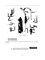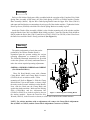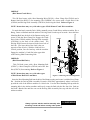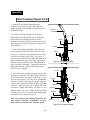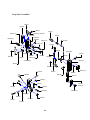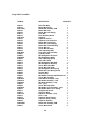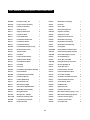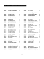
1
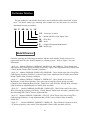
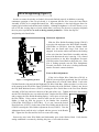
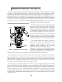
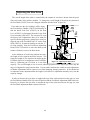
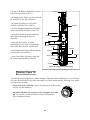
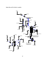
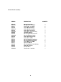
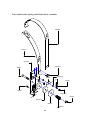
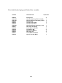
DELUXE STITCHER
C O M P A N Y
I N C .
Head Serial Number :
Date Purchased :
Where Installed:
(make/model of machine)
G8 Stitcher Head
OPERATION AND MAINTENANCE MANUAL
Wire Sizes: 23-28 Ga. Round and 21x25 Flat
Crown Size: 1/2” (13.5 mm)
Capacity: 2 sheets to 5/16” (8 mm)
Standard and Loop Stitch
Before using this Stitcher Head, all operators must study this manual and follow the
safety warnings and instructions. Keep these instructions with the G8 Stitcher Head
for future reference. If you have any questions, contact your local DeLuxe Stitcher
Company Graphic Arts Representative or Distributor.
WARNING!
G8 Stitcher Head
Machine operators and others in the work area should always wear
safety glasses to prevent serious eye injury from
fasteners and flying debris when loading, operating,
or unloading this machine.
Do not operate this stitcher head without all stitcher machine
guards in place. Do not modify the guards in any way.
Always disconnect the power supply before removing
any guards for servicing.
Never operate the machine with wire feeding through
the head unless there is stock above the clinchers,
otherwise serious damage may result.
Always turn power off when making adjustments. Always
disconnect the power cord before any disassembly work.
2
Table of Contents
Introduction ........................................................................................................4
Part Number Definition ....................................................................................5
Specifications ....................................................................................................7
Installation
......................................................................................................9
Pre-Inspection ................................................................................9
Inspection ......................................................................................9
Assembly........................................................................................11
Mounting ......................................................................................11
Operation
......................................................................................................13
Wire Threading ............................................................................13
Wire Straightening ........................................................................14
Adjustments and Settings ............................................................15
Maintenance ......................................................................................................21
Lubrication ....................................................................................21
Cleaning ........................................................................................22
How to Order Spare Parts..............................................................23
Replacing Spare Parts ..................................................................23
Troubleshooting ................................................................................................29
Formed Staple Chart ......................................................................29
Appendices ......................................................................................................31
Exploded Drawings......................................................................33
Part Number /Description Cross Reference..............................47
Optional Equipment.......................................................................... 50
Registration Card ............................................................................................52
Wear/ Replacement Parts ..............................................................................53
Warranty
......................................................................................................54
3
Introduction
Each Head in the G8 Stitcher Head Series is basically identical with respect to
operation. The style variations in the Heads mentioned below, occur in some of the
component parts used for adaptation to single stitch or gang stitch machines. As model
design changes are made, part numbers also change.
These Heads were designed with a side-feed element to eliminate the need for a
Swivel and to increase their reliability. Well suited for all makes and models of stitcher machines and collators, the G8-style Stitcher Head is user-friendly.
Typical Style Uses:
G8BHD ..............................................................No. 2 and M2 Wire Stitchers
G8MHD ..........................................................No. 17 and M17 Wire Stitchers
G8HD ................................................................Automatic Saddle-Stitchers,
................................................................Gang-Stitchers, Multibinders and Others
Examples of Replacement Heads for OEM Users*:
AM Graphics / Harris / Heidelberg / Sheridan
455, 562, 690 ................................................................G8HD24A
AM Graphics / Harris / Heidelberg / Sheridan 705 ....G8HD24A
Bourg ................................................................................G8HD24D
Christensen ......................................................................G8HD24A
Horizon SP, SPF ..............................................................G8HD24D
Macey Multibinder ........................................................G8HD24B
McCain..............................................................................G8HD24A
Rosback ............................................................................G8HD24B
* These are just a few examples of the replacement heads available for these OEM’s.
4
Part Number Definition
The part number for each Stitcher Head can be used to define the stitcher head itself, in most
cases. The Head’s model type, mounting style, nominal wire size and crown size can all be
determined from the part number.
G8
P
HD
24
A
1/2
1/2 = Crown size in inches
A = Mount and Wire Guide Spring Type
24 = Wire Size
HD = Head
P = Original Equipment Manufacturer
G8 = Model type
Model Differences
Generally speaking, the following part numbers indicate which Stitcher Heads can be used as
replacement heads for your Stitcher Machine or collating system*. Refer to Figure 1 for more
information.
• Style “A” - Models G8HD24A, G8HD24AL, G8HD2125A and G8HD23A. These Heads come
with a Short Wire Guide Spring Assembly (G20279A), Upper Cutter Adjustment Bar (G20245) and
a Thick, Round Clincher Plate Assembly (A9086A).
• Style “B” - Models G8HD24B, G8HD2125B, G8HD24BL. These Heads come with a Long Wire
Guide Spring Assembly (G20286A), a shorter Upper Cutter Adjustment Bar (G20245) and a Thick,
Round Clincher Plate Assembly (A9086A)
• Style “C” - Models G8HD24C, G8HD24CL, G8HD2125C. These Heads are for use on
Bolt-Mount / Crank-Driven Stitchers. They come with a Long Wire Guide Spring Assembly
(G20286A), Rear Mounting Bolt (G20341), Crank Drive Link (G20340), Driving Slide Assembly
(G20320A) but no Adjustment Rail or Clincher Plate Assembly.
• Style “D” - Models G8HD24D, G8HD24DL, G8HD2125D. These Heads come with a Long
Wire Guide Spring Assembly (G20286A), a Thick, Round Clincher Plate Assembly (A9086A) and a
Rear Mounting Bolt (G20367) but no Adjustment Bar.
• Style “E” - Models G8HD24E, G8HD24EL, G82125E. These Heads come with a Long Wire
Guide Spring(G20286A), a Long Adjustment Bar (G20251) and a Clincher Plate Assembly
(9086EAA)
• Style “F” - Models G8HD24F, G8HD24FL, G8HD2125F. These Heads are identical to Style
“A” Heads except they come with a Thick Adjustable Clincher Slide Assembly (9193A).
5
* These are just examples and should be used as reference only.
Figure 1 - Style Comparisons
6
Specifications
Weight
Shipping Weight . . . . . . . . . . . . . 11 lbs (5 kg)
Physical Dimensions
Height
. . . . . . . . . . . . . . . . . . 13-9/16” (34.5 cm)
Width
. . . . . . . . . . . . . . . . . . 2-3/4” (7 cm)
Stitching Capacity . . . . . . . . . . . . . . . . . Two Sheets to 5/16” (8 mm)
(stitching capacities are highly dependent on wire type, tensile strength and machine capacity)
Wire Types
. . . . . . . . . . . . . . . . . . 23 through 28 round or 21 x 25 flat
( 24 gauge round standard )
Crown Sizes
. . . . . . . . . . . . . . . . . . 17/32” (14mm)
. . . . . . . . . . . . . . . . . . 13/64” (5mm) Loop
Minimum Head Centers
. . . . . . . . . . . . . . . . . . 2-3/64” (52mm) at two sheets to
. . . . . . . . . . . . . . . . . . 1/16” (1.5mm) material thickness
. . . . . . . . . . . . . . . . . . loop = 56mm at two sheets to 2mm
Stitches Per Hour . . . . . . . . . . . . . . . . . . 20,000 or 12,000 with Loop Head
Replacement for: . . . . . . . . . . . . . . . . . . Interlake/Acme/Champion/
. . . . . . . . . . . . . . . . . . Magnatek/M200 heads,
. . . . . . . . . . . . . . . . . . 26/26D Model Heads, or Hohner
. . . . . . . . . . . . . . . . . . 52/8, 55/7 and 48/5 Heads
7
Dimensions
8
Installation
Pre-Inspection
Carefully inspect the condition of the shipping container before unpacking your G8 Stitcher Head.
If the container is broken or damaged and there is evidence that the stitcher head may be
damaged, immediately notify the carrier who delivered the head and the DeLuxe Stitcher Graphic Arts
Representative from whom the G8 Stitcher Head was purchased.
Inspection
As you carefully unpack the head, check to make sure all components were delivered and are in
good working order. Refer to Figure 2 in this manual for reference to the following pieces:
• G8 Manual
• 2.0mm Hex Key Wrench (G20374)
• 2.5mm Hex Key Wrench (G20361)
• 3.0mm Hex Key Wrench (G20360)
• 5.0mm Hex Key Wrench (G20362)
• 7.0mm Open End Wrench (G20364)
• Complete Wire Guide Spring Plate Assembly (G20278AA)
• Adjustment Knob Assembly (G20228A)
• Short (G20279A) or Long (G20286A) Wire Guide Spring Assembly
• Clincher Plate Assembly - Thick (9086A)
• Round (9083A) or Flat (9083C) Thick Clincher Points
• Clamp Block (9002) and Clamp Block Eccentric (G20124) or Rear Clamp Pin (G20366)
and Rear Mounting Bolt (G20367 or G20341)
• Either Clincher Plate Binder Nut (2091), Bolt (9088) and Thick Clincher Slide (9093A)
or Clincher Plate Binder Nut (2091), Bolt (9088), Adjustable Clincher Slide (9084B),
Clincher Slide Adjusting Screw (9087) and Clincher Slide Adjusting Lock Screw
(UA4808.7).
• Stitch Samples
9
G20362
G20286A
G20279A
G20361
G20360
G20367 or
G20341
G20278AA
G20366
G20374
G20364
G20124
G20228A
9002
9083A or
9083C
G20181
9086A
Figure 2 - Assembly
Pre-Installation
Please take a few moments to fill out the registration card located on page 52 prior to beginning
installation.
Always disconnect the power supply before
making any adjustments or servicing the head.
10
! WARNING
r
Assembly
Each new G8 Stitcher Head comes fully assembled with the exception of the Complete Wire Guide
Spring Plate Assembly (G20278AA), the Wire Guide Spring (G20279 or G20286) and the Clincher
Plate Assembly (9086A). Slip the Wire Guide Spring Bracket onto the Upper Wire Tube (G20181)
and rotate until the Bracket accommodates the wire payoff of the stitcher machine. Tighten the Socket
Head Cap Screw (G20288) to hold the Wire Guide Spring Bracket Assembly in place.
Attach the Clincher Plate Assembly (9086A) to the clincher mounting rail of the stitcher machine
using the Binder Nuts (2091) and Binder Bolts (9088) provided. Center the Clincher Slide (9084B or
9093A) under the Driver Bar (G20151) and Driver (G20152, G20352 or G20358) of the G8 and leave
the Bolts loose until the Head is firmly positioned. (See Figure 11).
Mounting
The quality and quantity of work that can be
produced by the DeLuxe Stitcher Heads is
dependent upon the operator making the various
operating adjustments as accurately as possible.
The following illustrated instructions are provided
so that the operator will clearly understand how to
make the various required operating adjustments.
G8HD24A, G8HD24B, G8HD24E and G8HD24F
(Slot Mount/Rail Drive)
G20362
G20162BA
9002
These G8 Head Models come with a Bonnet
Clamp Block (9002) and Clamp Block Eccentric
(G20124) for use on stitchers with a T-Slot
mounting rail. Refer to Figure 3. Slide the Clamp
Block into the T-slot on the stitcher, as shown. Align
G20124
the marks on the Eccentric with those on the Bonnet.
Next, slide the Head onto the Clamp Block and
against the stitcher machine. Make sure the Driving
Slide (G20162BA) and the Adjustment Bar
Figure 3 - Removing and Attaching Heads
(G20245 or G20251) are in their respective slots on
the stitcher machine. Rotate the 5mm Hex Key
Wrench (G20362), in the Eccentric as shown, to secure the G8 Head to the stitcher machine.
NOTE: For stitcher machines with no adjustment rail, remove the Cutter Block Adjustment
Bar (G20245 or G20251) and the Cutter Block Adjustment Connector (G20246).
11
G8HD24C
(Bolt Mount/Crank Drive)
This G8 Head comes with a Rear Mounting Bolt (G20341), a Rear Clamp Pin (G20366) and a
Bonnet Stud Nut (HN1213) for mounting. The G8HD24C also comes with a Crank Drive Link
(G20340) and Driving Slide Assembly (G20320A) for driving the Head. Refer to Figure 4.
NOTE: Instructions may vary with other types of Bolt Mount / Crank Drive machines.
To attach the head, rotate the Drive Pulley manually on any Crank-Driven stitcher machine, like a
Bourg, Camco or Rosback until the stitcher’s Driving Crank is at the top of its stroke. Insert the Rear
Mounting Bolt into the hole of the Bonnet casting and
secure it with the Rear Clamp Pin. Engage the Crank
G20340
Drive Link (G20340) with the Driving Slide Assembly
(G20320A) on the back of the stitcher head. The
Driving Slide Pin must be inserted in the lower hole of
the Link. (The lower hole of the Link is the one
opposite of the oil hole.) With the Link held in a
vertical position, line the head up with the machine.
G20320A
Engage the machine’s Crank Pin in the upper hole
of the Driving Shaft Connecting Link.
G8HD24D
(Bolt Mount/Rail Drive)
G20170
This G8 Head comes with a Rear Mounting Bolt
(G20367), a Rear Clamp Pin (G20366) and a Hex Jam
Nut (G20170) for mounting. Refer to Figure 4.
NOTE: Instructions may vary with other types
of Bolt Mount / Rail Drive machines.
G20367
G20366
Figure 4 - Removing and Attaching Heads
Insert the Rear Mounting Bolt into the hole of the Bonnet casting and secure it with the Rear Clamp
Pin. Position the Driving Slide Assembly Eccentric (G20320A) approximately where it will meet
up with the rails of the stitcher machine or a little lower. Line the Rear Mounting Bolt up with the
mounting hole in the stitcher machine and loosely secure the Bolt with the Hex Jam Nut. Push on
the Head’s Bender Bar until the cam on the Driving Slide Assembly lines up with the rail of the
stitcher machine.
Always cycle the stitcher machine manually after
mounting a head and before running under power
12
! WARNING
r
Operation
Wire Threading (Figures 5 & 6)
1. Slide the Wire Holder Retaining Spring
(G20183) over to the side and remove the Wire
Holder Assembly (G20559BA or G20301A) from
the Stitcher Head.
2. Pass the wire from the Spool over the Wire
Guide Spring Assembly (G20279A or G20286A),
between the Tension Pawl (G20283) and the
Tension Pawl Roller (G20285), between the two (2)
Wire Oiler Felts (G20293) and into the Upper Wire
Tube (G20181).
3. Turn the Feed Release Handle (G20119) clockwise so that the Small Feed Gear (G20112) on the
Feed Lever (G20132) is disengaged from the Large
Feed Gear Assembly (G20110A). Use a pair of
pliers to gently pull the wire off the Wire Spool and
guide it through the Upper Wire Tube, between the
Small and Large Feed Gears, into the Middle Wire
Tube Assembly (G20144A). Turn the Feed Release
Handle horizontally so that the Small and Large
Feed Gears are engaged.
G20279A or
G20286A
G20283
G20285
G20293
G20119
G20181
Figure 5 - Threading the Head
G20132
4. Turn the stitcher machine on and trip it until the
wire emerges from the Lower Wire Tube (G20199A)
in the Cutter Block Assembly (G20197A). If the
wire does not emerge, turn the Wire Straightener
Eccentric (G20206) and trip the stitcher until the
wire is visible to the right of the Left Wire Guide Bar
(G20141). Make sure the wire is leaving the Head
completely straight horizontally and that is is not
touching either the Left or Right Wire Guide Bar
(G20142) as it passes. Complete wire straightening
instructions can be found on page 14.
Note: Never operate the Stitcher Head with the
Wire Holder Assembly (G20559BA) in place
unless there is stock above the Clincher Points.
G20112
G20183
G20110A
G20144A
G20199A
G20559BA
or G20301A
G20197A
G20206
Figure 6 - Threading the Head
13
Wire Straightening (Figure 7)
In order to ensure the stitches are loaded, driven and clinched properly in addition to ensuring
continuous operation of the G8 style heads, it is important that the wire leaves the Cutter Block
Assembly (G20197A) in straight horizontal line. Wire straightness is the single biggest factor for
ensuring good stitches and stitcher head reliability. Although straightness is set at the factory, every
roll of wire has varying degrees of twist which make it necessary for the user to properly straighten
the wire prior to production as well as during normal production. Follow the steps for
straightening wire listed below.
Horizontal Adjustment
G20136A
G20183
G20200
G20559BA
or G20301A
G20265
G20206
Slide the Wire Holder Retaining Spring (G20183)
over to the side and remove the Wire Holder Assembly
(G20559BA or G20301A) from the Stitcher Head.
Make sure the Small and Large Feed Gears are
engaged. Activate the stitcher and observe the feeding
of the wire from the Cutter Block Assembly and take
note of the direction the wire is moving. Use a slotted
head screwdriver in the Wire Straightener Eccentric
(G20206) on the Cutter Block to adjust the wire. If the
wire is feeding upwards, turn the Wire Straightener
Eccentric clockwise. If the wire is feeding downward,
turn the Eccentric counter-clockwise.
Front-to-Back Adjustment
G20273
If the Left or Right Wire Guide Bars (G20141 or
G20142) are not properly positioned, the wire will rub
Figure 7 - Straightening the Wire
against them as it exits the Cutter Block. Look at the
G8 Head from the side past both the Right and Left Wire Guide Bars. Make sure there is a clear view
of the opening in the Fixed Wire Cutter (G20200) from the side of the G8 Head. If there is not, loosen
the Flat Head Machine Screws (G20215) securing the Wire Guide Bars to the Feed Gear Bracket
Assembly (G20136A) and move them out of the path of the wire. Tighten the Screws after making
sure the Wire Guide Bars are even with each other. Replace the Wire Holder
and re-engage the Wire Holder Retaining Spring. Load a piece of wire into
the Wire Holder. Using a mirror, check to make sure the wire in the Wire
Holder is lined up with the grooves in the Bender Bar Assembly
(G20147BA, G20347BA or G20357BA). If it is not, loosen the Socket Bender Bar
grooves
Head Set Screw (G20273) in the front of the Wire Holder and the Hex Nut
(G20226) securing the Wire Holder Adjustment Screw (G20265). Turn the
Adjustment Screw until the wire is aligned with the grooves in the Bender
Bar. Tighten the Hex Nut and Set Screw to secure this setting.
G20226
Remove the wire in the Wire Holder and load another piece in the Stitcher Head. Verify that the
setting established is accurate by checking this piece of wire with the mirror.
14
Adjusting the Lower Wire Tube (Figure 8)
In order to ensure the proper feeding of wire through the G8 Stitcher Head ensuring its continuous
operation, it is important that the wire leaves the Lower Wire Tube Assembly (G20199A) in straight
horizontal line and enters the Cutter Block Assembly without assistance. Wire straightness is the
single biggest factor for ensuring good stitches and stitcher head reliability. Although the position of
the Lower Wire Tube is set at the factory, transportation can cause the factory settings to change and
every roll of wire has varying degrees of twist which make it necessary for the user to properly
straighten the wire prior to production as well as during normal production. Follow the steps for
aligning the Lower Wire Tube listed below.
If the wire coming out of the Lower Wire Tube hits
the side of the Wire Straightener Roller (G20208B)
instead of passing over it, the groove in the Wire
Tube has to be aligned with the groove in the Roller
by adjusting the position of the Lower Wire Tube.
Turn the Wire Straightener Eccentric (G20206) so
that the maximum amount of space is allowed for the
wire between the two (2) Wire Straightener Rollers.
Loosen, but do not remove, the two (2) Socket Head
Set Screws (G20191) in the Cutter Block Assembly.
G20144A
G20191 (2)
One adjustment that can be made is to move the
Tube up or down. Make sure the Wire Tube is close
enough to the Wire Straightener Roller to ensure
continuous feeding of the wire, but not pressed
G20206
G20199A
against the Roller, which will stop the wire
G20208B
completely. Leaving a 0.010" (.025mm) space
between the Tube and the Wire Straightener Roller is
Figure 8 - Adjusting the Lower Wire Tube
a good gauge. Tighten the two (2) Set Screws at this
point and double check the space between the Tube and the Roller before proceeding.
The other adjustment that can be made is to tilt the Wire Tube toward or away from the Cutter Block.
If the wire feeding out of the Cutter Block is curving up then tilt the Wire Tube toward the Cutter
Block Assembly. If the wire is curving down then tilt the Wire Tube away from the Cutter Block
Assembly. Before tightening the Set Screws, verify that there is still at least a 0.010” clearance
between the Lower Wire Tube and the Wire Straightener Roller.
Once the wire is successfully feeding between the two (2) Wire Straightener Rollers, turn the Feed
Release Handle (G20119) to the off position, remove the Middle Wire Tube (G20144A) enough to cut
the wire as it exits from between the Large Feed Gear Assembly (G20110A) and the Small Feed Gear
(G20112) and remove the wire. Turn the Feed Release Handle to the on position again and activate
the stitcher head until the wire feeds out of the Lower Wire Tube. Make sure that the wire feeds
between the Wire Straightener Rollers without assistance, if not, make adjustments to the Lower Wire
Tube until it does.
15
Adjusting the Length of the Stitch Leg (Figure 9)
The following instructions illustrate how to
calibrate the G8 Stitcher Head the first time it is used
after mounting it to the stitcher machine. It also
illustrates how to manually adjust the Cutter Block
each time a different stitching capacity is required.
Adjust the compression setting on the stitcher
machine for the capacity of work to be stitched.
Make a few sample stitches and turn the stock away
from you to look at the results.
The length of each staple leg should equal the other,
meaning, the amount of wire on either side of the
stitch gap should be the same. The gap position is
controlled by the position of the Cutter Block
Assembly (G20197AA). As thicker work is stitched,
the Cutter Block must be moved further from the
Wire Holder Assembly in order to keep the legs of
the stitch even and the gap centered.
G20251
G20228A
G20245
G20246
G20289 (2)
G20237
G20143
G20197AA
Figure 9 - Adjusting the Stitch Leg
For G8 Heads mounted to a machine with an
adjuster rail, first loosen the two (2) Hex Head
Screws (G20289) securing the Lower Cutter Block Adjustment Bar and Cutter Block Adjustment
Connector (G20246) to the Upper Cutter Block Adjustment Bar (G20245 or G20251). For all G8
style Heads, place the Adjustment Knob (G20228A) over the Cutter Adjustment Stud (G20237) and
engage the teeth of the Cutter Block Adjustment Rack (G20143). To shorten the length of the left
staple leg, lengthen the length of the right staple leg or move the gap between the legs to the left: turn
the Adjustment Knob counter-clockwise. Run a couple of stitches to test this setting. To lengthen the
length of the left staple leg, shorten the length of the right staple leg or move the gap between the legs
to the right: turn the Adjustment Knob clockwise. If both legs are equal in length or if the gap between
the legs is centered, no more adjustment is necessary. Make sure to tighten the two (2) Hex Head
Screws securing the Lower Cutter Block Adjustment Bar and the Cutter Block Adjustment Connector
to the Upper Cutter Block Adjustment Bar.
If more adjustment is necessary, continue to move the Cutter Block Assembly towards or away from
the body of the G8 Stitcher using the Adjustment Knob and test after each adjustment.
16
Adjusting the Wire Draw
The overall length of the stitch is controlled by the amount of wire that is drawn from the spool
after each stroke of the stitcher machine. To change the overall length of the stitch, the position of
the Feed Rack (G20127) has to be changed within the Stitcher Head. (Figure 10).
First, make sure the wire feeding is off by turing
the Feed Release Handle (G20119) horizontally so
that the Small Feed Gear (G20112) on the Feed
Lever (G20132) is disengaged from the Large Feed
Gear Assembly (G20110A). The wire draw is set at
the factory but if adjustments have to be made for
specific stitcher equipment, a good place to start is to
align the top of the Feed Rack with “N” on the Feed
Slide (G20131) for normal stitching at with the “L”
for loop stitching. Turn the Feed Rack Adjustment
Knob (G20173) clockwise to move the Rack up and
counter-clockwise to move the Rack down.
MORE
WIRE
DRAW
G20173
Q
LESS
WIRE
DRAW
G20131
G20127
G20132
G20119
G20112
G20110A
As the thickness of work being stitched increases,
the length of wire required must also increase. The
longer the length of wire required, the further up the
Feed Rack has to be in comparison to the Feed Slide.
Figure 10 - Adjusting the Wire Draw
Start by calibrating the G8 Head at a two-sheet
capacity. The overall length of wire is correct when the gap between the staple legs allows only the
edge of a fingernail to pass between them. If your stitcher machine has a built-in stroke adjustment,
no further adjustments will be required, even when changing stitching capacities. If the stitcher has
no automatic stroke adjustment then the length of wire has to be adjustment manually every time the
capacity changes.
In order to increase the wire draw or lengthen the legs of the stitch and decrease the gap size, turn
the Feed Release Handle (G20119) to the off position and the Feed Rack Adjustment Knob clockwise.
Inversely, to decrease the wire draw or shorten the legs of the stitch and increase the gap size, turn
the Feed Rack Adjustment Knob counter-clockwise.
17
Aligning the Clincher Plate (Figure 11)
In order to produce properly clinched staples, the center of the Clincher Plate* (round or flat,
thick or thin) must be exactly in line with the Driver* (depending on the wire gauge being used) both
left-to-right and front-to-back. The following are
instructions for both types of adjustment.
Upper Screw
G20229
Front-to-Back
Manually activate the G8 until the Stitcher Head is
at the bottom of its stroke and the Driver is touching
the top of the Clincher Plate. Looking from the side
of the Stitcher Head, make sure the rib of the Driver
is aligned with the center of the gap between the
front and back plates of the Clincher Plate Assembly.
G20191 (2)
All adjustments are made to the screws in the back
of the G8 while the Stitcher Head is removed from
the Stitcher Machine. If the Driver is positioned in
front of the Clincher Plate then the upper Socket
Lower Screw
G20229
Head Set Screw (G20229) must be turned counter2091 (2)
clockwise until the Screw sticks out slightly from the
back of the Head, while the upper Screw remains
under flush. If the Driver is positioned in back of the
9093A or
9084B
Clincher Plate then the lower Socket Head Set Screw
must be turned counter-clockwise until it sticks out
Figure 11 - Clincher Plate Alignment
slightly from the back of the Head, while the lower
Screw remains under flush. Slight
adjustments to the Set Screws make significant differences in position. Once the position is set,
tighten the two (2) Socket Head Set Screws (G20191) in the side of the Stitcher Head.
Left-to-Right
Looking from the front of the Stitcher Head, make sure the Driver is centered directly above the
Clincher Slide (9093A or 9084B). If it is not, loosen the two (2) Clincher Plate Nuts (2091) and move
the entire Clincher Plate Assembly to the right or to the left. Secure this position while tightening the
Nuts again.
Make sure all guards are in place before
operating the stitcher head
! WARNING
r
* For a complete list of wear parts and replacement parts based on wire gauge and crown size, see
page 47 of this manual.
18
Adjusting the Clincher Points
The final position of the Clincher Points* (round
or flat) should be flush, or slightly above flush, with
the Clincher Plate* (round or flat) in order to achieve
a quality stitch. The best way to see the position of
the Clincher Points is to manually turn the stitcher
machine over. When the Driver* (depending on the
wire gauge being used) is at the lowest position of
its stroke, the Clincher Points are at their highest
position. Turn the stitcher machine just past this
point to reveal the Clincher Points’ position.
Clincher Points that do not pivot high enough will
produce a weak clinch, where Clincher Points that
pivot too high will cause poor stitch quality or cut
the stock being stitched.
9083A or
9083C
UA4808.7
9084B
If the clinch on the staple is not tight enough, the
Clincher Points (9083A or 9083C) have to be raised,
9087
assuming the Stitcher machine’s compression setting
is correct. If the legs of the staple are being pushed
back through the stock, the Clincher Points are set
Figure 12 - Adjusting Clincher Points
too high and have to be lowered. These adjustments
are specific to each stitcher machine and cannot be fully explained in this manual, since many
Machines have Clincher Lever adjustments built in. Consult the stitcher machine’s operating
manual for complete Clincher Point adjustment instructions when using non-adjustable Clincher
Plates. If the machine is using an Adjustable Clincher Plate, like the one shown in Figure 12, adjust
the Clincher Points as follows. Loosen the Set Screw (UA4808.7) on the top of the Clincher Slide
(9084B). Turn the Clincher Slide Adjustment Screw (9087) clockwise to lower the Clincher Points
and turn the Clincher Slide Adjustment Screw counter-clockwise to raise the Clincher Points. Once
the Clincher Point height is set, tighten the Set Screw on the front of the Clincher Slide.
Refer to the complete list of wear parts for the G8 style Stitcher Head, found in the back of this
manual on page 47. The Clincher Points and Clincher Plates necessary for a quality stitch are
specific to the crown size and wire gauge size used in each stitcher head.
Some style stitcher heads do not utilize moving Clincher Points, but rather a solid Clincher Plate as
shown in Figure 13. The legs of each stitch are bent when the wire is pushed through the stock and
hits the Clincher Plate, as opposed to the Clincher Points in moveable Clincher Plates coming up to
meet the wire. The resulting stitch will not lay as flat as one clinched with moving Clincher Points
though.
19
The only adjustment that can be made to a Solid
Clincher Plate is to make sure it is centered below
the Head’s Driver and even that adjustment can only
be made on multi-head stitcher machines.
FLAT CLINCH
SOLID CLINCH
Adjusting the Bender Bar Stop
Like other G8 Stitcher Head settings, the Bender
Bar Stop is set at the factory. The Stop controls the
position of the Bender Bar Latch (G20149) at the top
Figure 13 - Solid Clincher Plate
of the stitcher head’s stroke. If the Latch does not
fall within the proper area of the Driver Bar
(G20151), partially formed stitches will result or the wire feeding through the G8 will jam.
The right edge of the Bender Bar Latch should stick out from the Bender Bar at least 3/32” (2.5mm)
when the G8 reaches the top of its stroke. If the Latch does not protrude this far then the Bender Bar
Stop Screw (G20229) is set too high. If the Stop
Screw is set too low then the wire will hit the Bender
Bar rather than feeding below it for forming.
G20163A
G20189 (2)
G20190
G20273
G20229
Figure 14 - Adjusting the Bender Bar Stop
Remove the four (4) Screws securing the Feed
Gear Bracket Assembly (G20163A) to the G8; the
two (2) Socket Head Cap Screws (G20189) and the
two (2) Flat Head Machine Screws (G20190).
Remove the entire Bracket Assembly. Loosen, but
do not remove, the Set Screw (G20273) securing the
Stop Screw in the Bracket. Turn the Stop Screw
according to the adjustment necessary; clockwise to
raise the Bender Bar’s position within the Head and
counter-clockwise to lower the Bender Bar’s position.
Replace the Bracket Assembly on the G8 making
sure to align its Locating Pins with the holes in the
Bonnet Assembly (G20000A). Manually turn the
Large Feed Gear (G20110A) if its teeth are not
aligned with those on the Feed Rack (G20127).
Replace the Screws.
20
Maintenance
Your G8 Stitcher Head has been fully lubricated at the factory, but to insure continuous
superior operation and a longer life of the head, the operator should be sure that the G8 is
lubricated regularly and carefully maintained. The operator should periodically inspect all moving
parts for signs of wear and when required, replace the worn parts. Parts such as the Wire Cutters, the
Clincher Points and the Driver are subject to wear and have been so designed to be reversible to provide duplicate cutting and driving surfaces. If after continuous usage, the original cutting or gripping
surfaces of any of these parts show signs of wear, their position in the head can be reversed, thereby
providing a new surface and lengthening the life of the part. For a complete list of wear and replacement parts for your G8 style Stitcher Head, refer to page 53 in the back of this manual.
The following instructions are provided so that the operator will clearly understand how to lubricate
the Stitcher Heads and how to identify and remove any of the parts which may need to be replaced.
Always disconnect the power supply before
making any adjustments or servicing the head.
! WARNING
r
Lubrication (Figure 15)
Use any standard S.A.E. #10 oil for lubricating the heads. Heads that are in constant operation
should be lubricated daily. Heads that are operated periodically should be lubricated every five pound
wire spool change or every month, which ever comes first. Usually, only a drop of oil is required at
each lubrication point. Care must be taken that those parts of the head that contact the work to be
stitched are free of oil. Lubricate regularly instead of excessively. Excessive oiling will result in work
becoming spotted with oil. Use one drop of oil in the following lubrication points:
21
• the top of the Bonnet (G20000A) on either
G20131
side of the Feed Slide (G20131).
• the fittings on the Feed Lever Pivot Pin and
the Small Feed Gear Pin (G20262A).
• the Cutter Operating Lever Pivot Pin
(G20231) and Roller Pin (G20232).
G20000A
• the Wire Straightening Rollers (G20208B)
in the Cutter Block Assembly (G20197A).
• on the Wire Holder Assembly under the
G20262A
Wire Holder Retaining Spring Foot
(G20184).
• where the Wire Holder Assembly
(G20559BA) pivots in the Left and Right
Wire Guide Bars (G20141 and G20142).
G20184
G20231
G20149
• on the Bender Bar Latch (G20149) and the
G20232
Latch Release Cam (G20115).
G20115
G20141 & G20142
• in the Cutter Block Assembly, along side
G20198
the Cutter Operating Slide (G20198).
G20208B
G20197A
Figure 15 - Lubrication and Cleaning
Cleaning ( Figure 15)
In addition to proper lubrication, routine cleaning is important for the maintenance of your G8 Head.
The entire Head should be torn down and rebuilt every three months and the following areas should
be cleaned once a month:
• Large Feed Gear (G20110A): remove and wash in an oil-dissolving
solvent, dry and relubricate.
• Anywhere that dust, oil or pieces of wire and paper have built
up - for example: around the Clincher Points and around the
Wire Straightener Rollers.
22
Ordering Spare Parts
In time, you will need to replace some parts in your G8 style Stitcher Head. When this happens, first
locate the needed part in one of the following diagrams. Then locate the DeLuxe Stitcher part
number and contact your Graphic Arts Representative to order the part by the part number,
description and quantity.
Always power down the stitcher machine
before any maintenance or adjustments
are made to the stitcher head.
! CAUTION
r
Replacing Spare Parts (Figure 16)
The following are some of
the more common wear
parts which will need to be
removed and replaced in
your G8 style Stitcher
Head.
Some common
replacement parts do not
require the Stitcher Head to
be removed from the
stitcher machine. These
parts will be addressed first,
then a more specific
explanation for
disassembling and
replacing wear parts for the
G8 Stitcher Head will
follow.
G20136A
G20183
G20342
G20151
Removing and Replacing
the Wire Cutters
Figure 17
The Moving Wire Cutter
(G20145) has several
cutting surfaces, each of
which may be used by
rotating the Cutter’s
position on the Cutter
Operating Slide (G20198).
Worn Cutters can cause
G20344B
G20559BA
Driver
G20216 (2)
G20197AA
Bender Bar Asy
G20154A
Figure 16 - Replacing Spare Parts
23
poor stitch quality. To change or reverse the Moving
Wire Cutter, first remove the complete Cutter Block
Assembly (G20197A) from the stitcher head.
Loosen and remove the two (2) Socket Flat Head
Screws (G20216) on the front of the assembly and
pull the Cutter Block away from the G8 Head. Be
careful, the Cutter Operating Slide may spring out
from the Cutter Block Assembly. Loosen the Flat
Head Machine Screw (G20214) securing the Cutter
to the Slide and rotate the Cutter until a new cutting
surface is exposed. If there are no more sharp edges
available, remove the Screw completely and install a
new Moving Cutter. Replace the Machine Screw and
be sure to tighten it completely so that the Cutter
does not rotate on the Slide.
G20214
G20145
G20210
G20200
G20197A
G20198
G20196
Make sure the Cutter Operating Spring (G20210)
is resting against the Spirol Pin (G20217) in the
G20216 (2)
Cutter Block Assembly. Compress the Spring with
Figure 17 - Replacing the Wire Cutters
the edge of the Cutter Operating Slide and return the
Slide to its position in the Cutter Block Assembly. Support the Operating Slide by holding the back
of the Cutter Block and line up the two (2) Dowel Pins (G20223) in the back of the Assembly with
the Cutter Block Slide Plate (G20202). Replace the two (2) Socket Flat Head Screws and make sure
there is little or no play in the Assembly.
Like the Moving Cutter, the Fixed Wire Cutter (G20200) can be rotated when the cutting surface
is worn or replaced when no sharp surfaces are left. The complete Cutter Block Assembly has to be
removed from the Stitcher Head again by removing the two (2) Socket Flat Head Screws. Remove
the Cutter Operating Slide from the Cutter Block to reveal the Fixed Cutter. Loosen, but do not
remove, the Socket Head Cap Screw (G20196) on the front of the Cutter Block which secures the
Cutter. Rotate the Cutter until a new surface is exposed or replace it completely worn. The Cutter
can be rotated three or four times before needing to be replaced. Once the Cutter has been rotated
and before tightening the Cap Screw to secure the new position, make sure the Fixed Wire Cutter is
aligned correctly within the Cutter Block.
In order to obtain a clean edge on the cut wire, there can be no gap between the Moving and Fixed
Cutters. Replace the Cutter Operating Slide and compress it against the Cutter operating Spring until
the Moving Cutter just passes the hole in the Fixed Cutter. While holding this position, push the
Fixed Cutter against the Moving Cutter, using a small screwdriver as a lever. Tighten the Cap Screw
to secure the position of the Fixed Cutter, but be sure to test it once before re-assembling the Cutter
Block to the G8 by compressing the Cutter Operating Slide. The Moving Cutter must pass the Fixed
Cutter freely and with no visible gap.
Attach the Cutter Block Assembly on the G8 by aligning the Cutter Block with the Slide Plate and
replacing the two (2) Socket Head Flat Screws, being careful to support the Cutter Operating Slide.
24
Removing and Replacing the Driver (Figure 18)
If the staples produced have crowns that are buckled or corners that stick up, or if wire is jamming
between the Driver and Driver Bar, the Driver may
have to be reversed or replaced. Swing the Wire
Holder Retaining Spring (G20183) off of the Wire
Holder Assembly (G20559BA) and out of the way.
Remove the two (2) Driver Retaining Screws
(G20153) securing the Driver* to the Driver Bar
(G20151) and slide the Driver out of the Bender
Bar.* The ends of the Driver are identical so when
one end is worn or chipped, it can be reversed. If
both ends are worn, replace the existing Driver with
a new one. Add a little threadlocker to the Screws
before returning them to the Driver Bar. Replace the
Wire Holder Assembly and Wire Holder Retaining
Spring.
G20183
G20559BA
G20153 (2)
G20151
Figure 18 - Replacing the Driver
Removing and Replacing the Latch and
Latch Spring (Figure 19)
If multiple pieces of wire are being loaded in the Wire Holder Assembly (G20559BA) and not being
formed, the Latch (G20149) and/or Latch Spring may have to be replaced. Remove the Cap Screw
(G20171) on the back of the G8 Stitcher Head to release the Driving Slide Assembly (G20162A or
G20320A). Once the Slide has been released, swing the Wire Holder Retaining Spring out of the way
and remove the Wire Holder Assembly. Use the
Adjustment Knob Assembly (G20228A) to move the
G20161
Cutter Block out slightly so the Bender Bar
G20159
Assembly can be removed from the bottom of the
G20160
head. Remove the Bender Bar Friction Bushing
G20224
(G20161), the Bender Bar Friction Spring (G20160)
and the Bender Bar Friction Plug (G20159) from the G20150
G20149
back of the Bender Bar. Loosen the Set Screw
(G20156) in the front of the Bender Bar and remove
the Supporter Pivot Pin (G20155) and Supporter
G20156
Assembly (G20154A). Compress the Latch and
slide the Driver Bar (G20151) out the bottom of the
Assembly. Remove the Machine Screw (G20224)
G20155
G20151
securing the Bender Bar Latch Spring (G20150) and
remove the Spring. Slide the Latch out of the
Assembly as well.
G20154A
Replace the Latch Spring and Machine Screw.
Slide the Latch in through the right side of the Latch
25
Figure 19 - Replacing the Latch & Spring
Housing and compress it against the Spring. Insert the Driver Bar from the bottom of the Assembly
until the Latch drops into the profile slot in the Driver Bar. Assembly the Supporter to the Bender Bar
with the Supporter Pivot Pin inserted from the left
9083B or
side. Secure the Pivot Pin with the Set Screw, mak9083C (2)
ing sure there is free movement between the
Supporter and Bender Bar. Replace the Friction Plug
and Spring into the Bushing, compress the Supporter
Spring Plunger (G20342) and screw the Bushing into
the Bender Bar securely.
2091 (2)
9086A
Removing and Replacing the Clincher Points
(Figure 20)
The Clincher Point (9083B or C) is double-sided so
that when one side is worn, it can be reversed to
provide a new clinching surface and increase the life
9084B
or
9093A
of the part. A worn Clincher Point may cause
poorly formed staple legs. Loosen, but do not
remove, the two (2) Clincher Plate Nuts (2091) until
the Clincher Slide (9084B or 9093A) can be
Figure 20 - Replacing the Clincher Points
disengaged from the stitcher machine and slid out of
the Clincher Plate Assembly (9086A) or down
within it. Rotate the Clincher Points upwards until they could be pulled out. Reverse the Points when
one of their sides is worn or chipped or replace them. Rotate the Clincher Points downward before
replacing the Clincher Slide. Make sure the Points are engaged by the Slide before tightening the
Clincher Plate Nuts.
Disassembling the Stitcher Head (Figure 21)
Remove the G8 style Stitcher Head from the stitcher machine. On Clamp-mount style heads, loosen
the Clamp Block Eccentric (G20124) and remove the Stitcher Head from the Bonnet Clamp Block
(9002). On Bolt-mount style heads, loosen and remove the Bonnet Stud Nut (HN1213 or G20170)
while supporting the Head. Remove the Head from the stitcher machine and place it on a clean work
area.
Swing the Wire Holder Retaining Spring (G20183) away from the G8 and remove the Wire Holder
Assembly (G20559BA). Snap the Middle Wire Tube (G20144A) out of the Middle Wire Tube Clip
(G20244) and remove it from the Lower Wire Tube (G20199A) in the Cutter Block Assembly
(G20197AA). Remove the two (2) Cap Screws (G20189) and the two (2) Machine Screws (G20190)
securing the Feed Gear Bracket Assembly (G20136A) to the Bonnet Assembly (G20000A) and
remove the Feed Gear Bracket. Remove the two (2) Flat Head Screws (G20216) securing the Cutter
Block Assembly to the Bonnet and remove the Cutter Block. Remove the Cap Screw (G20171) from
the back of the G8 securing the Driving Slide Assembly (G20162A or G20320A) to the Feed Slide
(G20131) and remove both from the Bonnet Assembly. The Bender Bar Assembly* can also be slid
26
G20131
G20127
G20171
G20162A or
G20320A
G20124
G20000A
G20136A
G20164
G20132
G20268
G20189 (2)
G20262A
G20267
G20264
G20244
G20190 (2)
9002
G20202
G20183
G20199A
HN1213 or
G20170
G20144A
G20216 (2)
Bender Bar Asy
G20197AA
G20559BA
Figure 21 - Disassembling the Head
out from the bottom of the Bonnet at this time.
Remove the Feed Lever Spring Bushing (G20267) and Feed Lever Spring (G20268) from the Feed
Lever (G20132). Loosen, but do not remove, the Set Screw (G20264) securing the Feed Lever Pin
(G20262A) in the Bonnet Assembly and remove the Feed Lever Assembly from the Bonnet.
Any of these assemblies can now be taken apart for cleaning or repair. The Bonnet itself can also
be cleaned or checked for damage. Most common wear parts can be exchanged while the Head is still
assembled though. Reassembling the Head is as simple as reversing the method used to disassemble
27
the Head. Always turn the machine over manually anytime repairs or adjustments are made for the
safety of both the operator and the Stitcher Head.
Re-assembling the Stitcher Head (Figure 21)
1. Slide the Feed Slide Assembly into the Bonnet from the top. Make sure the Slide moves freely
within the Bonnet but has minimal side-to-side play. Slide the Bender Bar Assembly into the Bonnet
from the bottom, compress the Bender Bar Latch and press down the Supporter Assembly to
completely position the Bender Bar within the Bonnet.
2. Turn the Bonnet over and position the Driving Slide Assembly so that the Driving Slide Plunger
(G20164) rests in the notch of the Driver Bar and secure this position with the Cap Screw tightened
completely.
3. Assemble the Feed Gear Bracket Assembly to the Bonnet by first ling up the three (3) pins in the
Bracket with the holes in the Bonnet. Secure the Feed Gear Bracket with two (2) Cap Screws and two
(2) Machine Screws. The teeth of the Large Feed Gear Assembly (G20110A) may have to be lined
up manually with the teeth of the Feed Rack (G20127).
4. Re-assemble the Feed Lever Assembly to the Bonnet with the Feed Lever Pin (G20262A),
making sure the oil hole in the pin is facing downward. Secure the Pin by tightening the Set Screw
(G20264) in the side of the Bonnet. Replace the Feed Lever Spring through the Feed Lever and secure
it with the Feed Lever Spring Bushing (G20267).
5. Assemble the Cutter Block Assembly to the Cutter Block Slide Plate (G20202) with two (2) Flat
Head Screws. There should be little or no play once the Block is secure, but if there is any
movement, remove both the Cutter Block and the Slide Plate. Re-assemble the Slide Plate to the
Bonnet so that it slides side to side but not up and down.
6. Return the Wire Holder Assembly to its position under the Wire Holder Retaining Spring and the
Middle Wire Tube to its position by inserting it into the Lower Wire Tube and snapping it into place
in the Middle Wire Tube Clip.
28
Troubleshooting (Figure 22)
The quality and quantity of work that can be produced with the G8 Stitcher Head is
dependent upon the operator making all adjustments as accurately as possible and carefully
maintaining the head. The cause of staple imperfections usually can be traced to inaccurate settings
or normal wear of moving parts. In the event of trouble of this nature occurring, the operator can, by
referring to the following troubleshooting chart, quickly locate and remedy the cause or causes of the
trouble.
The following is a brief list of problems and solutions which should cover the majority of situations
encountered when stitching with the G8 Stitching Head. In the event of problems of this nature
occurring, the operator can, by referring to the following troubleshooting chart, quickly locate
the solutions.
PROBLEM:
Crown Not Straight
SOLUTION : Straighten the wire. (See page 14) Align the Clincher Points. (See
page 18) Reverse or replace the worn or broken Driver. (See page 25) Make
sure the Cutters are aligned and not dull. (See page 16) Check for
correct wire size and strength being used. Check for correct work thickness setting.
PROBLEM:
Leg(s) Buckled
SOLUTION : If the ends of an unformed piece of wire are not smooth,
the Wire Cutters are worn. Check for wear and rotate or replace if needed.
(See page 16) Make sure the Cutters are aligned properly. (See page 17)
Make sure the correct wire size is being used and that the wire is straight.
(See page 14).
PROBLEM:
Corner Buckled
Check the Driver for a chipped corner and rotate or replace it
if needed. (See page 25) Align the Wire Holder. (See page 14) Straighten
wire. (See page 14) Check the tensile strength of the wire or use thicker wire.
SOLUTION :
PROBLEM:
Clinch Too Loose
SOLUTION : The Clincher Points are too low and need adjusting. (See page 19)
The compression of the stitcher machine is insufficient and needs to
be increased.
PROBLEM:
Left Leg Too Short / Right Leg Too Long
the position of the Cutter Block Assembly by moving
it away from the Head. (See page 16)
SOLUTION : Adjust
Figure 22 - Troubleshooting
29
PROBLEM :
Left Leg Too Long / Right Leg Too Short
SOLUTION: Adjust the position of the Cutter Block Assembly by moving it
away toward the Head. (See page 16)
PROBLEM :
Staple Legs Too Long or Too Short
SOLUTION: Correct the overall wire draw by repositioning the Feed Slide
within the G8 Head. (See Page 17)
PROBLEM :
Left Leg Missing
SOLUTION: Straighten the wire. (See page 14) The Wire Holder Assembly is
not aligned properly with the groove in the Bender Bar.
PROBLEM :
Legs are Spread or Contracted
SOLUTION: Straighten the wire. (See page 14)
PROBLEM :
Legs Stray Forward or Backward Consistently
The Clincher Points are not aligned properly front to back. (See
page 18) Straighten the wire. (See page 14)
SOLUTION:
PROBLEM :
Stitch Stray Randomly In and Out and Front to Back
Straighten the wire. (See page 14) Make sure the Cutters are
aligned properly. (See page 23) Check the tensile strength of the wire or use
thicker wire.
SOLUTION:
PROBLEM :
Partially Formed Stitches
SOLUTION: The Bender Bar Latch is not engaging with the Driver Bar, either
may be worn. The Bender Bar Stop Screw is set too low. (See page 20)
PROBLEM :
Weak crown, crown breaks off after stitch
SOLUTION: Align the Wire Holder with the grooves in the Bender Bar
(See page 14). Check the tensile strength and size of the wire being used.
PROBLEM :
No wire being drawn
SOLUTION: Make sure the Feed Release Handle is turned to the “on”
position and the Feed Gears engaged. (See page 13)
Figure 23 - Troubleshooting
30
The G8 Stitcher Head
31
32
Bonnet Sub-Assembly
G20264
Bolt-mount Heads
G20170
G20368
G20274
G20367
G20118
G20273 (2)
G20121
G20341
G20119
HN1213
G20167 (2)
G20133A
9002
G20366
G20122A (2)
Clamp-mount Heads
G20269
G20251
G20275
G20182
G20245
G20196 (2)
G20250 (2)
G20264
G20246
G20244
G20191 (2)
G20214 (2)
G20126
G20289 (2)
G20240 (2)
G20249 (2)
G20236
G20239 (2)
G20220
Discs should be cupped
G20229 (2)
G20124
G20242
G20115
G20235
G20191
G20140
G20204
G20241 (4)
G20237
G20190 (2)
G20243
G20231
G20202
G20234 (2)
G20230A
G20113 (2)
G20233
G20175 (2)
33
G20232
Bonnet Sub-Assembly
ITEM No.
DESCRIPTION
9002
G20113
G20115
G20118
G20119
G20121
G20122A
G20124
G20126
G20133A
G20140
G20167
G20170
G20175
G20182
G20190
G20191
G20196
G20202
G20204
G20214
G20220
G20229
G20230A
G20231
G20232
G20233
G20234
G20235
G20236
G20237
G20239
G20240
G20241
G20242
G20243
G20244
G20245
G20246
G20249
G20250
G20251
G20264
G20269
G20273
G20274
G20275
G20289
G20341
G20366
G20367
G20368
HN1213
Bonnet Clamp Block
Supporter Guide Plate
Latch Release Cam
Feed Release Handle Cam
Feed Release Handle
Feed Release Plunger
Feed Slide Retaining Screw Assembly
Bonnet Clamp Eccentric
Tube Pivot Plate
Feed Release Spring Block Assembly
Follower Ball Bearing
Screw, M4x.7x10 FHCS
Hex Jam Nut M8x1.25
Screw M4x.7x6 SHCS
Feed Gear Shaft Plate
Screw M3x.5x10- FHMS - Slotted
Screw, M4x.7x8 SHSS
Screw M3x.5x6 SHCS
Cutter Block Slide Plate
Upper Cutter Block Guide
Screw M4x0.7x8 FHMS
Hex Nut M5x.8
Set Screw M6x1x12
Cutter Operating Lever Assembly
Cutter Operating Lever Pivot Pin
Cutter Operating Lever Roll Pin
Cutter Operating Lever Roller
E-Ring- 3/16"
Follower Bearing Shaft
Tube Pivot Screw
Cutter Block Adjustment Stud
Disc Washer Spring
Cutter Block Adjustment Washer
Screw M4x0.7x6 SHCS
Cutter Adjustment Bar - Lower
Dowel Pin 1/4x9/16
Tube Pivot Clip
Cutter Adjustment Bar - Upper
Cutter Block Adjustment Connect
Cutter Block Washer
Screw M4x.7x14
Cutter Adjustment Bar - Upper
Screw M5x.8x5 SHCS
Spirol Pin 3/16x5/8
Screw M4x.7x4 SHSS
Hex Jam Nut, M6x1
Ball Spring Plunger
Screw M4x.7x16
Rear Mounting Bolt
Rear Clamp Pin
Rear Mounting Bolt
Feed Release Handle Cap
Bonnet Stud Nut
34
QUANTITY
1
2
1
1
1
1
2
1
1
1
1
2
1
2
1
2
3
2
1
1
2
1
2
1
1
1
1
2
1
1
1
2
2
4
1
1
1
1
1
2
2
1
2
1
2
1
1
2
1
1
1
1
1
Feed Lever and Feed Gear Assemblies
G20262A (2)
G20268
G20132
G20263 (2)
G20112
G20267
G20264
G20181
G20266
G20140
G20110A
G20262A
G20138 (2)
G20129
G20189 (2)
G20215 (2)
G20111A
G20128
G20195
G20142
G20273
G20187
G20114
G20186
G20180
G20241
G20261
G20190 (2)
G20229
G20215 (2)
G20214 (2)
G20143
G20316
G20184
G20256
G20175
G20196 (2)
G20141
G20183
35
Feed Lever and Feed Gear Assemblies
ITEM No.
DESCRIPTION
G20110A
G20111A
G20112
G20114
G20128
G20129
G20132
G20138
G20140
G20141
G20142
G20143
G20175
G20180
G20181
G20183
G20184
G20186
G20187
G20189
G20190
G20195
G20196
G20214
G20215
G20229
G20241
G20256
G20261
G20262A
G20263
G20264
G20266
G20267
G20273
G20316
Large Feed Gear Assembly
Feed Pinion Assembly
Small Feed Gear
Feed Pinion Shaft
Large Feed Gear Washer
Small Feed Gear Washer
Feed Lever
Feed Pinion Bearing
Follower Ball Bearing
Wire Guide Bar-Left
Wire Guide Bar-Right
Cutter Block Adjustment Rack
Screw M4x.7x6 SHCS
Flat Washer M6
Upper Wire Tube
Wire Holder Retaining Spring - Long
Wire Holder Retaining Spring Foot
Feed Gear Friction Spring
Feed Gear Friction Strip
Screw M3x.5x20
Screw M3x.5x10- FHMS- Slotted
Set Screw M6x1x8
Screw M3x.5x6 SHCS
Screw M4x0.7x8 FHMS
Screw M5x.8x10, FHMS
Set Screw M6x1x12
Screw M4x0.7x6 SHCS
Cutter Block Scale
Wire Holder Retaining Spring Screw
Feed Lever Pin Assembly
Feed Lever E-Ring
Screw M5x.8x5 SHCS
Follower Bearing Pin
Feed Lever Bushing
Screw M4x.7x4 SHSS
Wire Holder Retaining Spring - Short
36
QUANTITY
1
1
1
1
1
1
1
2
1
1
1
1
1
1
1
1
1
1
1
2
2
1
2
2
4
1
1
1
1
2
2
1
1
1
1
1
Driving and Feed Slide Assemblies
G20264
G20173
G20179
G20131
G20340
G20177
G20176 (2)
G20174
G20127
G20171
G20171
G20170
G20321
G20162
G20320
G20170
G20169
G20165
G20165
G20167 (2)
G20167 (2)
G20163A
For rail-driven Heads
G20323A
G20164
For crank-driven Heads
37
G20164
Driving and Feed Slide Assemblies
ITEM No.
DESCRIPTION
G20127
G20131
G20162
G20163A
G20164
G20165
G20167
G20169
G20170
G20171
G20173
G20174
G20176
G20177
G20179
G20264
G20320
G20321
G20323A
G20340
Feed Rack
Feed Slide
Driving Slide
Cutter Operating Ramp Assembly
Driving Slide Plunger
Driving Slide Spring
Screw, M4x.7x10 FHCS
Driving Slide Plunger Screw
Hex Jam Nut M8x1.25
Screw M8x1.25x12
Feed Rack Knob - Knurled
Feed Rack Adjustment Stud
Screw M4x.7x12 SHCS Low Head
Feed Rack Adj Knob Pointer
Screw M3x.5x4, SHCS
Screw M5x.8x5 SHCS
Driving Slide - Crank Drive
Crank Link Screw
Cutter Operating Ramp Assembly
Crank Drive Link
38
QUANTITY
1
1
1
1
1
1
2
1
1
1
1
1
2
1
1
1
1
1
1
1
Bender Bar and Wire Holder Assemblies
G20161
G20160
G20159
G20342
G20224
G20149
G20150
G20344B
G20148B
G20154A
G20346
G20156
G20431 (4)
G20155
G20135
G20252
G20255
G20151
G20253
G20147BA (24-28 rd)
G20347BA (21X25 flat)
G20357BA (23 rd)
G20265
G20152 (24-28 rd)
G20352 (21X25 flat)
G20358 (23 rd)
G20254
G20226
G20273
G20559BA
39
G20153 (2)
Bender Bar and Wire Holder Assemblies
ITEM No.
DESCRIPTION
G20135
G20147BA
G20148B
G20149
G20150
G20151
G20152
G20153
G20154A
G20155
G20156
G20159
G20160
G20161
G20224
G20226
G20252
G20253
G20254
G20255
G20265
G20273
G20342
G20344B
G20346
G20347BA
G20352
G20357BA
G20358
G20431
G20559BA
Dowel Pin M5x24
Bender Bar Assembly, 24W
Latch Housing Removable
Bender Bar Latch
Bender Bar Latch Spring
Driver Bar
Driver, 24W
Driver Retaining Screw
Supporter Assembly
Supporter Pivot Pin
Supporter Pivot Pin Screw
Bender Bar Friction Plug
Bender Bar Friction Spring
Bender Bar Friction Bushing
Bender Bar Latch Spring Screw
Hex Nut M4x.7
Wire Hook
Wire Hook Spring
Wire Hook Spring Screw
Hook Pivot Pin
Wire Holder Eccentric Adjustment Screw
Screw M4x.7x4 SHSS
Supporter Spring Plunger
Supporter Spring - Heavy
Supporter Guide Pin
Bender Bar Assembly,21x25
Driver, 21x25W
Bender Bar Assembly, 23W
Driver, 23W
Screw, M2.5x.45x12
Wire Holder Assembly 1/2
40
QUANTITY
1
1
1
1
1
1
1
2
1
1
1
1
1
1
1
1
1
1
1
1
1
1
1
1
1
1
1
1
1
4
1
Cutter Block Assembly
G20210
G20198
G20214
G20145 or
G20145C
G20197A
G20200 or
G20600C
G20219 (4)
G20223
G20226 (2)
G20191 (2)
G20217
G20196
G20206
G20211
G20212
G20199A
G20213 (2)
G20196
G20208B (2)
41
Cutter Block Assembly
ITEM No.
DESCRIPTION
G20145
G20145C
G20191
G20196
G20197A
G20198
G20199A
G20200
G20206
G20208B
G20210
G20211
G20212
G20213
G20214
G20217
G20219
G20223
G20226
G20600C
Moving Wire Cutter
Moving Cutter - Carbide
Screw, M4x.7x8 SHSS
Screw M3x.5x6 SHCS
Cutter Block Assembly
Cutter Operating Slide
Lower Wire Tube Assembly
Fixed Wire Cutter
Wire Straightener Eccentric
Wire Straightener Roller
Cutter Operating Spring
Cutter Wire Shield
Wire Straightener Roll Stud
Wire Straightener Roll Clip
Screw M4x0.7x8 FHMS
Spirol Pin M5x12
Wire Straightener Disc Spring
Dowel Pin 1/8x1/4
Hex Nut M4x.7
Fixed Cutter - Carbide
42
QUANTITY
1
1
2
2
1
1
1
1
1
2
1
1
1
2
1
1
4
1
2
1
Wire Guide Bracket, Spring and Clincher Plate Assemblies
G20286A
G20279A
G20278A
G20288 (2)
G20297
G20285
G20290 (2)
G20283
G20284
G20288
G20234 (2)
G20298
G20293 (2)
G20292
G20287
43
Wire Guide Bracket, Spring and Clincher Plate Assemblies
ITEM No.
DESCRIPTION
G20234
G20278A
G20279A
G20283
G20284
G20285
G20286A
G20287
G20288
G20290
G20292
G20293
G20297
G20298
E-Ring- 3/16"
Wire Guide Spring Plate Assembly
Wire Guide Spring Assembly - Short
Tension Pawl
Tension Pawl Spring
Tension Pawl Roller
Wire Guide Spring Assembly - Long
Wire Oiler Felt Spring
Screw, M4x.7x8 SHCS
Flat Washer, M5
Wire Oil Felt Washer
Wire Oiler Felt
Screw, M6x1x40 SHCS
Nylock Lock Nut, M6x1
44
QUANTITY
2
1
1
1
1
1
1
1
3
2
1
2
1
1
Loop Stitch Assemblies
G20210
G20198
G20214
G20161
G20145 or G20145C
G20219 (4)
G20160
G20300A
G20200 or
G20600C
G20226 (2)
G20159
G20216 (2)
G20191 (2)
G20342
G20224
G20147BA
G20212
G20149
G20206
G20199A
G20211
G20150
G20196
G20344B
G20213 (2)
G20208B (2)
G20154A
G20196
G20313A
G20431 (4)
G20346
G20135
G20156
G20155
G20304A
G20151
G20226
G20310
G20306
G20314
(24-25 rd)
G20311
G20309A
G20273 (2)
G20312
G20305
G20301A
G20265
G20255
45
G20153 (2)
Loop Stitch Assemblies
ITEM No.
DESCRIPTION
G20135
G20145
G20147BA
G20149
G20150
G20151
G20153
G20154A
G20155
G20156
G20159
G20160
G20161
G20191
G20196
G20198
G20199A
G20200
G20206
G20208B
G20210
G20211
G20212
G20213
G20214
G20216
G20219
G20224
G20226
G20255
G20265
G20273
G20300A
G20301A
G20304A
G20305
G20306
G20309A
G20310
G20311
G20312
G20313A
G20314
G20342
G20344B
G20346
G20347BA
G20357BA
G20431
Dowel Pin M5x24
Moving Wire Cutter
Bender Bar Assembly, 24W
Bender Bar Latch
Bender Bar Latch Spring
Driver Bar
Driver Retaining Screw
Supporter
Supporter Pivot Pin
Supporter Pivot Pin Screw
Bender Bar Friction Plug
Bender Bar Friction Spring
Bender Bar Friction Bushing
Screw, M4x.7x8
Screw, M3x.5x6 SHCS
Cutter Operating Slide
Lower Wire Tube Assembly
Fixed Wire Cutter
Wire Straightener Eccentric
Wire Straightener Roller
Cutter Operating Spring
Cutter Wire Shield
Wire Straightener Roll Stud
Wire Straightener Roll Clip
Screw, M4x0.7x8 FHMS
Screw, M4x.7x25 SFHS
Wire Straightener Disc Spring
Bender Bar Latch Spring Screw
Hex Nut, M4x.7
Hook Pivot Pin
Wire Holder Eccentric Adjustment Screw
Screw, M4x.7x4 SHSS
Cutter Block Assembly - Loop
Wire Holder Assembly - Loop
Wire Hook Assembly - Loop
Anvil - Loop
Screw, M3x.5x25 SHCS
Wire Holder Lever Assembly - Loop
Wire Holder Roller Lever Spring
Spring Anchor Screw
Spirol Pin, M3x12
Supporter Assembly - Loop
Driver - Loop
Supporter Spring Plunger
Supporter Spring - Heavy
Supporter Guide Pin
Bender Bar Assembly, 23W
Bender Bar Assembly, 23W
Screw, M2.5x.45x12
46
QUANTITY
1
1
1
1
1
1
2
1
1
1
1
1
1
2
2
1
1
1
1
2
1
1
1
2
1
2
4
1
3
1
1
2
1
1
1
1
1
1
1
1
1
1
1
1
1
1
1
1
4
Part Number / Description Cross-Reference
G20000A
Bonnet Assembly - G8
1
G20150
Bender Bar Latch Spring
1
G20110A
Large Feed Gear Assembly
1
G20151
Driver Bar
1
G20111A
Feed Pinion Assembly
1
G20152
Driver, 24W
1
G20112
Small Feed Gear
1
G20153
Driver Retaining Screw
2
G20113
Supporter Guide Plate
2
G20154A
Supporter Assembly
1
G20114
Feed Pinion Shaft
1
G20155
Supporter Pivot Pin
1
G20115
Latch Release Cam
1
G20156
Supporter Pivot Pin Screw
1
G20118
Feed Release Handle Cam
1
G20159
Bender Bar Friction Plug
1
G20119
Feed Release Handle
1
G20160
Bender Bar Friction Spring
1
G20121
Feed Release Plunger
1
G20161
Bender Bar Friction Bushing
1
G20122A
Feed Slide Retaining Screw Asy
2
G20162
Driving Slide
1
G20124
Bonnet Clamp Eccentric
1
G20162BA
Driving Slide Assembly Eccentric
1
G20126
Tube Pivot Plate
1
G20163A
Cutter Operating Ramp Assembly
1
G20127
Feed Rack
1
G20164B
Driver Slide Plunger Eccentric
1
G20128
Large Feed Gear Washer
1
G20165
Driving Slide Spring
1
G20129
Small Feed Gear Washer
1
G20167
Screw, M4x.7x10 FHCS
2
G20130
Feed Adjustment Block
1
G20169B
Driving Slide Plunger Screw Ecc
1
G20131
Feed Slide
1
G20170
Hex Jam Nut M8x1.25
1
G20132
Feed Lever
1
G20171
Screw M8x1.25x12
1
G20133A
Feed Release Spring Block Assembly 1
G20173
Feed Rack Knob - Knurled
1
G20135
Dowel Pin M5x24
1
G20174
Feed Rack Adjustment Stud
1
G20136A
Feed Gear Bracket Assembly
1
G20175
Screw M4x.7x6 SHCS
3
G20138
Feed Pinion Bearing
2
G20176
Screw M4x.7x12 SHCS Low Head
2
G20140
Follower Ball Bearing
1
G20177
Feed Rack Adj Knob Pointer
1
G20141
Wire Guide Bar-Left
1
G20179
Screw M3x.5x4, SHCS
1
G20142
Wire Guide Bar-Right
1
G20180
Flat Washer M6
1
G20143
Cutter Block Adjustment Rack
1
G20181
Upper Wire Tube
1
G20144A
Middle Wire Tube Assembly
1
G20182
Feed Gear Shaft Plate
1
G20145
Moving Wire Cutter
1
G20183
Wire Holder Retaining Spring - Long
1
G20145C
Moving Cutter - Carbide
1
G20184
Wire Holder Retaining Spring Foot
1
G20147BA
Bender Bar Assembly, 24W
1
G20186
Feed Gear Friction Spring
1
G20148B
Latch Housing, Removable
1
G20187
Feed Gear Friction Strip
1
G20149
Bender Bar Latch
1
G20189
Screw M3x.5x20
2
47
Part Number / Description Cross-Reference
G20190
Screw M3x.5x10- FHMS- Slotted
4
G20236
Tube Pivot Screw
1
G20191
Screw, M4x.7x8 SHSS
5
G20237
Cutter Block Adjustment Stud
1
G20195
Set Screw M6x1x8
2
G20239
Disc Washer Spring
2
G20196
Screw M3x.5x6 SHCS
6
G20240
Cutter Block Adjustment Washer
2
G20197A
Cutter Block Assembly
1
G20241
Screw M4x0.7x6 SHCS
5
G20198
Cutter Operating Slide
1
G20242
Cutter Adjustment Bar - Lower
1
G20199A
Lower Wire Tube Assembly
1
G20243
Dowel Pin 1/4x9/16
1
G20200
Fixed Wire Cutter
1
G20244
Tube Pivot Clip
1
G20202
Cutter Block Slide Plate
1
G20245
Cutter Adjustment Bar - Upper
1
G20204
Upper Cutter Block Guide
1
G20246
Cutter Block Adjustment Connect
1
G20206
Wire Straightener Eccentric
1
G20249
Cutter Block Washer
1
G20208
Wire Straightener Roll
2
G20250
Screw M4x.7x14
2
G20208B
Wire Straightener Roller
2
G20251
Cutter Adjustment Bar - Upper
1
G20210
Cutter Operating Spring
1
G20252
Wire Hook
1
G20211
Cutter Wire Shield
1
G20253
Wire Hook Spring
1
G20212
Wire Straightener Roll Stud
1
G20254
Wire Hook Spring Screw
1
G20213
Wire Straightener Roll Clip
2
G20255
Hook Pivot Pin
1
G20214
Screw M4x0.7x8 FHMS
5
G20256
Cutter Block Scale
1
G20215
Screw M5x.8x10, FHMS
4
G20261
Wire Holder Retaining Spring Screw
1
G20216
Screw M4x.7x25 SFHS
2
G20262A
Feed Lever Pin Assembly
2
G20217
Spirol Pin M5x12
1
G20263
Feed Lever E-Ring
2
G20219
Wire Straightener Disc Spring
4
G20264
Screw M5x.8x5 SHCS
5
G20220
Hex Nut M5x.8
1
G20265
Wire Holder Eccentric Adj Screw
1
G20223
Dowel Pin 1/8x1/4
1
G20266
Follower Bearing Pin
1
G20224
Bender Bar Latch Spring Screw
1
G20267
Feed Lever Bushing
1
G20226
Hex Nut M4x.7
2
G20268
Feed Lever Spring
1
G20228A
Adjustment Handle Assembly
1
G20269
Spirol Pin 3/16x5/8
1
G20229
Set Screw M6x1x12
2
G20273
Screw M4x.7x4 SHSS
2
G20230A
Cutter Operating Lever Assembly
1
G20274
Hex Jam Nut, M6x1
1
G20231
Cutter Operating Lever Pivot Pin
1
G20275
Ball Spring Plunger
1
G20232
Cutter Operating Lever Roll Pin
1
G20278A
Wire Guide Spring Plate Assembly
1
G20233
Cutter Operating Lever Roller
1
G20278AA
Complete W/G Spring Plate Asy
1
G20234
E-Ring- 3/16"
1
G20279A
Wire Guide Spring Assembly - Short
1
48
Part Number / Description Cross-Reference
G20283
Tension Pawl
1
G20346
Supporter Guide Pin
1
G20284
Tension Pawl Spring
1
G20347BA
Bender Bar Assembly,21x25
1
G20285
Tension Pawl Roller
1
G20352
Driver, 21x25W
1
G20286A
Wire Guide Spring Assembly - Long
1
G20357BA
Bender Bar Assembly, 23W
1
G20287
Wire Oiler Felt Spring
1
G20358
Driver, 23W
1
G20288
Screw, M4x.7x8 SHCS
3
G20360
Hex Key Wrench 3.0mm
1
G20289
Screw M4x.7x16
2
G20361
Hex Key Wrench 2.5mm
1
G20290
Flat Washer, M5
2
G20362
Clamp Wrench 5.0mm
1
G20292
Wire Oil Felt Washer
1
G20364
Open End Wrench
1
G20293
Wire Oiler Felt
2
G20366
Rear Clamp Pin
1
G20297
Screw, M6x1x40 SHCS
1
G20367
Rear Mounting Bolt
1
G20298
Nylock Lock Nut, M6x1
1
G20368
Feed Release Handle Cap
1
G20300A
Cutter Block Assembly - Loop
1
G20374
Hex Key Wrench 2.0mm
1
G20301A
Wire Holder Assembly - Loop
1
G20431
Screw, M2.5x.45x12
4
G20304A
Wire Hook Assembly - Loop
1
G20559BA
Wire Holder Assembly 1/2
1
G20305
Anvil - Loop
1
G20600C
Fixed Cutter - Carbide
1
G20306
Screw M3x.5x25- SHCS
1
HN1213
Bonnet Stud Nut
1
G20309A
Wire Holder Lever Assembly - Loop
1
PW516
Washer 5/16
1
G20310
Wire Holder Roller Lever Spring
1
18182
Clincher Slide
1
G20311
Spring Anchor Screw
1
18183
Clincher Slide Adjustment Block
1
G20312
Spirol Pin M3x12
1
18184
Clincher Slide Block Clamp
1
G20313A
Supporter Assembly - Loop
1
18186
Clincher Slide Adjustment Screw
1
G20314
Driver - Loop
1
2091
Clincher Plate Binder Nut
2
G20316
Wire Holder Retaining Spring - Short
1
7024B
Clincher Point Flat - 1/2
2
G20320
Driving Slide - Crank Drive
1
7253A
Clincher Plate Assembly - 1/2
1
G20320A
Driving Slide Assembly
1
9002
Bonnet Clamp Block
1
G20321
Crank Link Screw
1
9083A
Clincher Point - Thick, Round
2
G20323A
Cutter Operating Ramp Assembly
1
9086A
Clincher Plate - Thick
1
G20340
Crank Drive Link
1
9088
Clincher Plate Binder Bolt
2
G20341
Rear Mounting Bolt
1
9093A
Clincher Slide - Thick
1
G20342
Supporter Spring Plunger
1
G20344
Supporter Spring
1
G20344B
Supporter Spring - Heavy
1
49
Optional Equipment
In addition to the standard features offered with the G8 Stitcher Head, optional equipment items can
be purchased to better accommodate your stitching needs. The following kits can be purchased from
your Graphic Arts Representative.
G8KC
The G8 Crank Drive Kit is available to owners of all styles of rail-driven G8 Heads who need to
convert, for whatever reason, their existing G8 head to a crank-driven model. Included in this Kit are
the Rear Clamp Pin, Rear Mounting Bolt, Bonnet Stud Nut, the Crank Drive Link and a complete
assembly of the Link-Driven Driving Slide.
For more information about purchasing the G8KC or for technical support when making the
conversion from rail-driven to crank-driven, contact your local Graphic Arts Representative.
To avoid risk of personal injury never loosen clamp
handle unless load on stand is supported.
! WARNING
r
G8KL (Figure 24)
The standard G8 Head with 24 gauge wire can be converted to a Loop style by exchanging the
following three sub-assemblies: the Wire Holder Assembly, the Cutter Block Assembly and the
Bender Bar Assembly. Refer back to pages 23 through 28 for complete disassembly and reassembly
instructions.
Contact your DeLuxe Stitcher Graphic Arts Representative or the DeLuxe Stitcher Customer
Service Department for ordering information or for additional technical information on other wire
sizes
G20300AA
G20317AA
G20301A
Figure 24 - Loop Stitch Kit
50
G8KS
The G8 Stop Stitch Kit is another optional purchase for the G8 Stitcher Head owner. It is
designed for use with the DeLuxe Stitcher G8 series Heads. The G8KS mounts on the Adjustment
Rail of many Saddle Stitchers like, McCain. This kit stops the feeding of wire through the Stitcher
Heads by pushing open the Feed Release Handles (thereby stopping the stitch) when it receives a
signal from the calipers of the Stitcher.
The G8KS Stop Stitch Kit comes complete with all the components necessary for converting your
existing stitcher machine, along with fully illustrated instructions. Call your Graphic Arts
Representative for more information.
To avoid risk of personal injury never loosen clamp
handle unless load on stand is supported.
! WARNING
r
G8KT
The G8KT is a Stop Stitch Toggle Kit specifically designed for users of McCain Stitchers using both
26/26D and G8 Stitcher Heads.
The Electrical Box, Box Cover and Toggle Switch replace your machine’s existing equipment to
make switching between the two styles of Stitcher Heads easier. This Kit comes complete with a
wiring diagram and replacement electrical box. But for more information or for more technical support, contact your local Graphic Arts Representative.
51
53
LIMITED WARRANTY
DeLuxe Stitcher Company warrants to the original retail purchaser
that this product is free from defects in material and workmanship and
agrees to repair or replace, at DeLuxe Stitcher’s option, any defective
product within 90 days from the date of purchase. This warranty is not
transferable. It covers damage resulting only from defects in material or
workmanship and does not cover conditions or malfunctions resulting from
normal wear, neglect, abuse or accident.
This warranty is in lieu of all other express warranties. Any warranty of
merchantability or fitness for a particular purpose is limited to the duration
of this warranty. DeLuxe Stitcher shall not be liable for any incidental or
consequential damages.
Some states do not allow limitations on how long an implied warranty lasts,
or the exclusion or limitation of incidental or consequential damages, so
the above limitations or exclusions may not apply to you. This warranty
gives you specific legal rights and you may also have other rights which
vary from state to state.
To obtain warranty service you must return the product, at your expense,
together with proof of purchase to an authorized
DeLuxe Stitcher Company Graphic Arts Dealer.
Always use genuine DeLuxe Stitcher parts. When ordering parts, please identify the
part number, the part name, the wire size and crown size of your Stitcher.
DeLuxe Stitcher Company, Inc.
6635 West Irving Park Road
Chicago, Illinois 60634 -2410
Phone: 773 -777-6500 800- 634 -0810
Fax: 773 -777-0156 800 - 417-9251
E-mail: [email protected]
Web Site: http:// www.deluxestitcher.com
54
DBSG80401