1
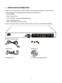
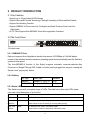
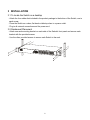
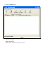
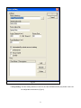
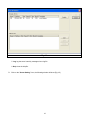
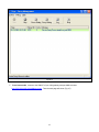
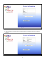
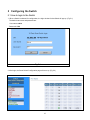
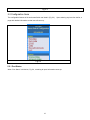
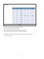
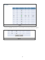
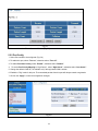
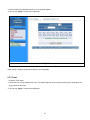
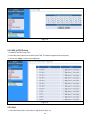
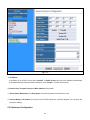
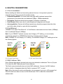
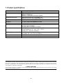
Smart Access Web Management Switch
USER’S GUIDE
1
TABLE OF CONTENTS
1
UNPACKING INFORMATION ............................................................................................ 3
2
PRODUCT INTRODUCTION ............................................................................................. 4
2.1 Key Features.................................................................................................................... 4
2.2The Front Panel ................................................................................................................ 4
2.2.1 100BASE-TX Port...................................................................................................... 4
2.2.2 Cabling ...................................................................................................................... 4
2.2.3 Status LEDs............................................................................................................... 4
2.3 The Rear Panel ................................................................................................................ 5
2.3.1 Power Socket ............................................................................................................ 5
3
INSTALLATION.................................................................................................................. 6
3.1 To locate the Switch on a desktop.................................................................................... 6
3.2 Rackmount Placement ..................................................................................................... 6
4
SMART FUNCTIONS SETTINGS ...................................................................................... 7
4.1 Start Smart Function ........................................................................................................ 7
5
CONFIGURING THE SWITCH......................................................................................... 15
5.1 How to login to the Switch.............................................................................................. 15
5.2 Configuration Items ........................................................................................................ 16
5.2.1 Port Status ............................................................................................................... 16
5.2.2 Port Config .............................................................................................................. 19
5.2.3 VLAN ....................................................................................................................... 20
5.2.4 Trunk ....................................................................................................................... 21
5.2.5 802.1p/TOS Priority ................................................................................................. 22
5.2.6 QoS ......................................................................................................................... 22
5.2.7 General System Configuration................................................................................. 23
5.2.8 Advanced Configuration .......................................................................................... 24
6.
HELPFUL SUGGESTIONS.............................................................................................. 27
6.1 Prior to Installation ......................................................................................................... 27
6.2 Fast Ethernet ................................................................................................................. 27
6.3 MAC Address Table........................................................................................................ 27
7.
PRODUCT SPECIFICATIONS ......................................................................................... 28
2
1 UNPACKING INFORMATION
Thank you for purchasing this Switch. Before continuing, please check the contents of the
product package. The package should contain the following items:
.One (1) Switch
.One (1) Power Cord
.Four (4) Rubber Feet (for desktop placement)
.One (1) Rack Mount Kit
.One (1) CD (Utility and User’s Guide)
If any of the above items is missing, please contact your place of purchase immediately.
Switch (19 inches case )
Power Cord
Rubber Feet
Rack Mount Kit
CD (Utility and User’s Guide)
3
2 PRODUCT INTRODUCTION
2.1 Key Features
.Support up to 24 port-based VLAN Groups
.Support Store-and-Forward Technology Filtering/Forwarding to Eliminate Bad Packets
.Support Non-blocking Function
.Support IEEE802.3x Flow-control for Full-duplex and Back Pressure Flow-control for
Half-duplex
.All TP Ports Support Auto-MDI/MDI-X and Auto-negotiation Functions
2.2The Front Panel
19 inches case
2.2.1 100BASE-TX Port
Each port supports Auto-Negotiation function that senses 10/100Mbps in Full/Half-duplex
modes of the attached device's maximum operating speed and automatically sets the Switch to
operate at that speed.
The Auto-MDI/MDI-X function of this Switch supports automatic crossover detection-Any
Crossover or Straight Through CAT.5 cable (or better) can be plugged into any port, making the
Switch a true "plug-n-play" device.
2.2.2 Cabling
Port Type
Cable Type
Connector
10BASE-T
Category 3, 4 or 5 TP RJ-45
100BASE-TX Category 5, 5E TP
RJ-45
2.2.3 Status LEDs
This Switch comes with a complete range of LEDs. The table below lists each LED’s name,
color and a brief description of its function.
Name
Color
Function
PWR
Green
Lit: Power "On"
Ports 1~24
Green
Lit: When the port has a valid physical connection with another device.
LINK/ACT
Ports 1~24
FD/COL
Blinks: When the port is sending or receiving data (Activity).
Yellow
Lit: When the port is set to Full-Duplex mode.
Blinks: When a collision is detected in Half-Duplex mode.
4
2.3 The Rear Panel
19 inches case
2.3.1 Power Socket
The Power Socket is designed to be used with the power cord included in the product package.
‧Attach the female end of the power cord to the male power connector on the back panel.
‧Attach the male end of the power cord to a grounded power outlet.
5
3 INSTALLATION
3.1 To locate the Switch on a desktop
.Attach the four rubber feet included in the product package to the bottom of the Switch, one in
each corner.
.Place the Switch on a clean, flat desk or tabletop close to a power outlet.
.Plug in all network connections and the power cord.
3.2 Rackmount Placement
.Attach one rack mounting bracket on each side of the Switch’s front panel and secure each
bracket with the provided screws
.Use the other provided screws to secure each Switch to the rack.
6
4 SMART FUNCTIONS SETTINGS
4.1 Start Smart Function
The Switch has a built-in smart function that can be accessed through a web browser and
provides users with more effective management of the local area network (LAN). It can also
operate using default settings to make it a “dumb” Switch.
The Switch’s configuration page can be accessed from either the local area network (LAN) side
or from the WAN side of the network. (From Internet side, Remote Control Management):
1. To connect to the Switch’s configuration page from your LAN, just type the Switch’s IP
address in IE’s address box to show the page.
2. To connect to the Switch’s configuration page from Internet (Remote Control Management),
please follow the steps below:
A. Please ask your LAN administrator to map port #8888(or your choice), on the network’s gateway to the IP
address of the PC running the management program “vega.exe”.
B. Execute vega.exe which is on the CD accompanied by the Switch on a PC located in the same local area
network.(Fig 4-1)
Fig 4-1
7
C. The program will show.(Fig 4-2)
Fig 4-2
Note: In the above window, there are 6 function icons that you can use to control the program:
1. Start: Start the program.
2. Stop: Stop the program.
3. Server Setting: Setting the server’s parameters. (Fig 4-3)
8
Fig 4-3
4. Proxy Setting: View the existing Switches in this LAN, and also add/delete/modify any Switch in the LAN
for configuration convenience. (Fig 4-4)
9
Fig 4-4
5. Log: log the server’s activity messages into a log file.
6. Help: view the help file.
D. Click on the “Server Setting” icon, the following window will show.(Fig 4-5)
10
Fig 4-5
E. Please change the Server Port from “80” to “8888”, and press OK for it to take effect. The next window
shows that it runs using port 8888.(Fig 4-6)
11
Fig 4-6
F. From internet side, connect to the WAN IP of your LAN gateway with port 8888 as below:
http://XXX.XXX.XXX.XXX:8888/proxy.htm . Then the web page will show. (Fig 4-7)
12
Fig 4-7
G. Select the Switch to be configured from the left side and the device information will be shown on the right.
(Fig 4-8).
Fig 4-8
13
Click on the “Configure this Device” to start the configuration of the selected Switch.(Fig 4-9)
Fig 4-9
14
5 Configuring the Switch
5.1 How to login to the Switch
1. When a Switch is selected for configuration, the login window for that Switch will pop up. (Fig 5-1)
The default user name and password are:
User name: admin
Password: 1234
Fig 5-1
2. After login, the Smart Switch Configuration page will come up. (Fig 5-2)
15
Fig 5-2
5.2 Configuration Items
The configurable features of the web smart Switch are listed in (Fig 5-3). Upon selecting any item from the list, a
page with detailed information on that item will come up.
Fig 5-3
5.2.1 Port Status
When “Port Status” is clicked on, Fig 5-4, containing all ports information comes up.
16
Fig 5-4
Link Status – Indicates the link status of each port ON/OFF.
Speed –Indicates Link Speed of each port 10/100.
Duplex –Indicates Half-duplex or Full-duplex connection on each port
Flow Control –Indicates Flow Control status of each port enable/disable.
For example, if we want to know the number of packets received or transmitted on port 4:
1. Select Port 4. (Fig 5-5)
17
Fig 5-5
2. Click on the “Counters” button (Fig 5-6), and the information we are looking for will be seen on Fig 5-7.
Fig 5-6
18
Fig 5-7
3. You can click on the “Reset Counters” button (Fig 5-7), to reset the counter number.
5.2.2 Port Config
1. Select Port number to be configured. (Fig 5-8)
2. To enable this port, select “Turn on”, otherwise select “Turn off”.
3. To enable Port-base Priority, select “Enable”, otherwise select “Disable”.
4. To set the Port Priority Mapping to “High Queue”, select “High Queue”, otherwise select “Low Queue”.
5. Change the default VLAN ID, it is available only if the tag based VLAN is enable.
6. Enable the “Tag” mode for this port. The transmitted packets from this port will always contain a tag header.
7. Click on the “Apply” to save the configuration changes.
Fig 5-8
19
5.2.3 VLAN
1. Select port-based VLAN or tag-based VLAN. (Fig 5-9)
Fig 5-9
2. Click on the “Apply” to enable and save selection.
3. Clink on the “Set Vlan” to edit the VLAN configuration.
5.2.3.1 Port Based VLAN
1. Select VLAN group number. It supports up to 24 VLAN Groups. (Fig 5-10).
2. Select VLAN Group Members (ports that are members of this VLAN).
3. Click on the “Apply” to save the configuration.
Fig 5-10
5.2.3.2 Tag Based VLAN
1. Select VLAN Group number. It supports up to 24 VLAN Groups. (Fig 5-11).
2. Enter the VID, it supports the range of 1 to 31.
20
3. Select VLAN Group Members,which are to be grouped together.
4. Click on the “Apply” to save the configuration.
Fig 5-11
Note: Group 1 (All ports are group members) is not changeable.
5.2.4 Trunk
1. Enter the Trunk menu.
2. Select the port to be grouped in this trunk. This switch supports one trunk group and any port combination can
be grouped into this trunk.
3. Click on the “Apply” to save the configuration.
21
Fig 5-12
5.2.5 802.1p/TOS Priority
1. Enter 802.1p/TOS Priority menu
2. Select the priority value for every 802.1p and TOS. This switch supports two level of priority.
3. Click on the “Apply” to save the configuration.
Fig 5-13
5.2.6 QoS
1. Select the Priority Ratio. (Low Queues : High Queue) (Fig 5-14)
22
2. Click on the “Apply” to save the configuration.
Fig 5-14
5.2.7 General System Configuration
23
Fig 5-15
A. IP address:
If the Switch is not a DHCP Client, select “Disable” for DHCP Client and fill out the IP Address, Subnet Mask
and Default Gateway information fields. Otherwise, select “Enable” in DHCP Client column.
B. Boot Version, Firmware Version and MAC Address of the Switch.
C. Device Name, Model Name, and Description of the switch (needs to be filled out by user).
D. Parent's Name or IP Address (if more than one S.A.W.M. switch are connected together, you can show the
root by this setting).-Needs to be filled out.
5.2.8 Advanced Configuration
24
Fig 5-16
To change Login Name and Password:
1. Type in the Login Name. The default Login Name is admin.
2. Enter a new password. The default password is 1234.
3. Confirm your password in the Confirm Password field.
4. Click on the “Change” to save your changes.
To restore the factory default settings:
1. Click on the “Reset to Default”. A warning dialog box appears. (Fig 5-17)
25
Fig 5-17
2. Click on the “OK”. All your Switch’s settings will be restored to its factory default values.
To upgrade the switch’s firmware:
Please visit our website for available firmware upgrades on this Switch.
www.cnet.com.tw
www.cnetusa.com
26
6. HELPFUL SUGGESTIONS
6.1 Prior to Installation
Before installing the Switch and connecting network devices, it is important to plan the
network's layout. Things you should consider include:
•
Dedicated Bandwidth: File servers and other high-traffic hardware improve their
performance if they have their own dedicated 10Mbps, 100Mbps bandwidth.
•
•
•
Full-duplex: Determine which devices support Full-duplex connections.
Fast Ethernet: Make sure rules for cable lengths and categories are followed.
Auto-negotiation: Devices with different speeds may be easily swapped when the other
end of the cable is fixed to a port with Auto-negotiation.
6.2 Fast Ethernet
100BASE-TX is called "Fast Ethernet". In Fast Ethernet, data travels ten times faster (100Mbps)
than in traditional Ethernet (10Mbps).
Note: If your 10BASE-T network currently uses Category 5 TP cabling, you can instantly
upgrade the network to a 100BASE-TX network by changing network devices.
Note: 100BASE-TX use Category 5 TP cabling. The standard Category 5 TP cabling pin-out as
the following figures:
EIA/TIA
568A
1 W/Green
2 Green
3 W/Orange
4 Biue
5 W/Blue
6 Orange
7 W/Brown
8 Brown
RJ-45 Jack Front View
P2
P1 P3
EIA/TIA
568B
P4
1 W/Orange
2 Orange
3 W/Green
4 Biue
5 W/Blue
6 Green
7 W/Brown
8 Brown
P2
P1 P3
P4
RJ-45 Jack Front View
6.3 MAC Address Table
Every Ethernet data packet includes both source and destination addresses. This six (6) bytes
ID is called the MAC (Media Access Control) Address.
The Switch can automatically learn and store MAC addresses. However, the MAC address
table is volatile: it disappears when the Switch is powered “OFF” or reset.
Note: When the network needs reconfiguration, we recommend you to turn off the power first.
After all nodes have been moved, turn the Switch back "ON" to rebuild the internal MAC
address table.
27
7. Product specifications
Product Name
Ports
Standards
Forwarding/Filtering Rate
Configuration Interface
Auto-MDI-X
Reset Button
LED Indicators
Environment
Power Supply
Certifications
Dimensions
CSH-2400W
24 100BASE-TX/10BASE-T Ports
IEEE 802.3 10BASE-T
IEEE 802.3u 100BASE-TX
IEEE 802.3x Flow Control for Full-Duplex Operation
14880 packets/second per port@10Mbps, max
148800 packets/second per port@100Mbps, max
IE Web browser
All TP ports support Auto-MDI/MDI-X Function
Reload IP, User Name and Password to default value
One (1) for Power
One (1) per port for Link/ACT
One (1) per port for Full-Duplex or Collision
Operating Temperature: -20° ~ 45° C (-4° ~ 113° F)
Storage Temperature: -40° ~ 80° C (-40° ~ 176° F)
Humidity: 10% ~ 90% Non-condensing
Internal full range switching power supply
Input voltage: 100 ~ 240 +-10%V AC 50/60 Hz
CE, FCC
442 x 185 x 44 mm (17.40 x 7.28 x 1.73 inches)
FCC WARNING
This equipment has been tested and found to comply with the limits for a Class A computing device pursuant to Part 15 of FCC
Rules, which are designed to provide reasonable protection against electromagnetic interference in a commercial environment.
Changes or modifications to the equipment not expressly approved by the party responsible for compliance could void the
user's authority to operate the equipment.
CE MARK WARNING
This is a Class A product. In a domestic environment this product may cause radio interference in which case the user may be
required to take adequate measures.
28