1
MICROPROCESSADORES
O
M I C R O P R O C E S S A D O R
8 0 8 6
1
O Microprocessador 8086
Introdução
O microprocessador 8086 é um microprocessador com uma arquitectura de 16 bits, com um
conjunto de cerca de 123 instruções, tem um bus de endereços de 20 bits, os seus registos são de
16 bits e uma pre-fetch queue de 6 bytes (memória do tipo FIFO na qual são colocadas as
instruções de código a serem executadas a seguir).
Porquê o estudo do 8086?
Trata-se de um microprocessador cuja arquitectura está na base de todos os processadores da
série 80x86. Qualquer tipo de microprocessador Intel do 80186 ao Pentium III é retro compatível
com o 8086, podendo trabalhar como se de um 8086 se trata-se.
Desta forma o 8086 é o ponto de partida ideal para que se possa compreender o funcionamento de
uma gama completa de microprocessadores.
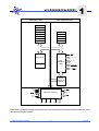
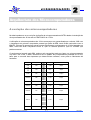
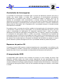
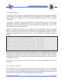
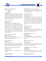
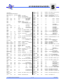
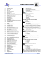
Arquitectura interna
As funções internas do processador 8086 estão divididas em duas unidades lógicas de
processamento. A primeira é a BIU (Bus Interface Unit) e a segunda a EU (Execution Unit), tal
como se pode ver no diagrama de blocos da figura 1.
Luís Miguel Charrua Figueiredo
1-1
E.N.I.D.H.
MICROPROCESSADORES
O
M I C R O P R O C E S S A D O R
Execution Unit
8 0 8 6
1
Bus Interface Unit
AX
BX
CX
DX
SP
BP
SI
DI
CS
DS
SS
ES
IP
BHE,S7
16 bit ALU
Bus
Interface
Unit
Flags
4
A19-A16 ,S3 -S6
16
AD15-AD0
3
INTA,RD,WR
3
OT/R,DEN,ALE
6 byte
Instruction
Queue
TEST
INT
NMI
RQ,GT0,1
LOCK
Control & Timming
2
QS0-QS1
3
S2 -S0
3
HOLD
HLDA
2
CLK
RESET
READY
MN/MX
GND
VCC
Figura 1 - Diagrama de blocos do 8086.
Estas duas unidades interagem directamente, mas normalmente funcionam assincronamente como
dois processadores isolados.
Luís Miguel Charrua Figueiredo
1-2
E.N.I.D.H.
MICROPROCESSADORES
O
M I C R O P R O C E S S A D O R
8 0 8 6
1
Bus Interface Unit
A BIU trata das funções de busca e colocação em queue de instruções, leitura e gravação de
operandos e realocação de endereços. Esta unidade trata também do controlo do bus.
Para realizar estas funções, a BIU possui: registos e segmentos, registos de comunicação interna,
indicador de instrução, queue de registos, somador de endereços e lógica de controlo do
barramento.
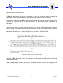
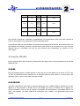
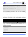
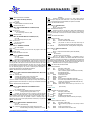
A BIU utiliza o mecanismo chamado fluxo de instrução para implementar a arquitectura pipeline. O
registo queue permite que haja uma pre-fetch de até 6 bytes de código de instrução (4 bytes no
caso do 8088). Sempre que a queue tenha 2 bytes livres, e a EU não esteja a executar operações
de escrita ou leitura em memória, a BIU irá efectuar uma operação de pre-fetch. Como o
barramento de dados é de 16 bits, a BIU efectua um pre-fetch de 2 bytes por ciclo.
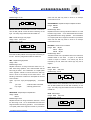
Figura 2 - (a) Ciclo sequêncial de busca e execução de um microprocessador sem pipeline. (b) A arquitectura pipeline do 8086 permite à EU executar as
instruções sem os atrasos associados à busca de instruções.
Quando o registo queue está completo, e a EU não está a executar operações de escrita/leitura na
memória, a BIU não efectua ciclos de barramento. Estes tempos por inactividade das vias são
chamados Idle States.
Quando a BIU está a executar uma pre-fetch, e a EU a executar operações de escrita/leitura da
memória ou I/O, a BIU completa primeiro a pre-fetch e só depois atenderá o pedido da EU.
Luís Miguel Charrua Figueiredo
1-3
E.N.I.D.H.
MICROPROCESSADORES
O
M I C R O P R O C E S S A D O R
8 0 8 6
1
Execution Unit
A unidade de execução é responsável pela descodificação e execução de todas as instruções de
código. A EU é constituída por uma ALU (Aritmethic Logic Unit), flags de estado e controlo, oito
registos de uso geral e lógica de controlo de queue.
A EU processa as instruções no registo de queue da BIU, processa a descodificação destas
instruções, gera endereços de operandos - se necessário -, transfere estes endereços para a BIU,
requisitando ciclos de leitura/escrita na memória ou I/O e processa a operação especificada pela
instrução sobre os operandos. Durante a execução a EU testa as flags de estado e controlo,
alterando-as se necessário conforme o resultado da instrução corrente.
Geralmente o registo de queue contém pelo menos um byte de código de instrução fazendo com
que a EU não necessite de esperar pela busca em memória da instrução seguinte.
Quando a EU executa uma instrução de salto, ou desvio, ela transfere o conteúdo para uma nova
posição de memória, neste instante, a BIU reinicializa a queue passando a executar a pre-fetch a
partir da nova localização de memória.
Os registos do 8086
Os registos podem ser classificados em 4 grupos:
Registos de uso geral ou de dados;
Registos de ponteiro e de índice;
Registos de segmento;
Registos de estado ou flags e indicadores de instrução.
Registos de dados
Cada um dos registos de dados AX, BX, CX e DX, pode ser usado como dois registos de 8 bits
independentes, passando a ser designados como por ex.: AH e AL, em que AH é o byte mais
significativo e AL o menos significativo de AX.
Apesar de normalmente serem usados para operações aritméticas de 8 e 16 bits, operações
lógicas e transferência de dados, por vezes têm funções específicas.
Luís Miguel Charrua Figueiredo
1-4
E.N.I.D.H.
MICROPROCESSADORES
O
M I C R O P R O C E S S A D O R
8 0 8 6
1
AX (Acumulador)
O registo AX ou acumulador, e como tal está envolvido em tipos específicos de operações como IN
(entradas de dados) e OUT (saídas de dados), multiplicação, divisão e operações de ajuste
decimal codificado em binário.
BX (Base)
O registo BX é frequentemente usado como um registo base para referenciar posições de
memória. Nesses casos, o BX guarda o endereço base de uma tabela ou vector no qual posições
específicas são referenciadas adicionando-se um valor de deslocamento.
CX (Contador)
O registo CX funciona como um registo de 16 bits para contar o número de bytes ou palavras
numa dada string, durante operações com strings de caracteres e em operações interactivas. Por
exemplo se n palavras devem ser movidas de uma área de memória para outra, o registo CX irá
conter inicialmente o número total de palavras a serem movidas, e será decrementado à medida
que cada palavra ou byte for transferido. O CX é também usado como contador de 8 bits para
instruções de deslocamento e rotação.
DX (Dados)
O registo DX é usado em operações de multiplicação para armazenar parte de um produto de 32
bits (os 16 bits mais significativos), ou em operações de divisão para armazenar o resto.
Pode também ser usado em operações de IN e OUT para especificar o endereço de uma porta de
I/O.
Registos de Ponteiro e Índice
Os registos de ponteiros e índice são usados para armazenar valores de deslocamento de forma a
aceder a posições de memória muito usadas, tais como a stack, ou blocos de dados de acordo
com uma organização vectorial. Os ponteiros SP e BP, são usados para guardar deslocamentos
no segmento de stack corrente da memória, enquanto os dois registos de índice SI e DI, são
usados para guardar deslocamentos no segmento de dados da memória.
Existem algumas excepções a estas regras, tal como em operações em que dados são
transferidos de uma posição para outra, com as posições de origem e destino indicadas por SI e DI
respectivamente.
Uma característica importante dos quatro registos é que podem ser usados em operações
aritméticas e lógicas, possibilitando assim que os valores de deslocamento neles contidos sejam
resultados das operações anteriores.
Luís Miguel Charrua Figueiredo
1-5
E.N.I.D.H.
MICROPROCESSADORES
O
M I C R O P R O C E S S A D O R
8 0 8 6
1
SP (Stack pointer)
É o ponteiro da stack (pilha), e aponta para a posição de topo da stack, é o registo usado por
defeito nas operações de PUSH e POP.
BP (Base pointer)
É o ponteiro da base, permite o acesso a dados dentro do segmento da stack. Normalmente, este
registo é usado para referências parâmetros que devem ser acedidos através da stack.
SI (Segment index)
É usado como registo de índice em alguns modos de endereçamento indirecto. É também usado
para guardar um deslocamento que vai endereçar a posição do operando fonte em operações com
strings.
DI (Data index)
É usado como índice em alguns modos de endereçamento indirecto. É também usado para
guardar a posição de destino do operando em operações com strings.
Registos de Segmento
As áreas de memória alocadas para código de programa, dados e stack (pilha) são endereçados
separadamente. Existem quatro blocos de memória endereçados disponíveis, chamados
segmentos, cada um com 64 Kbytes.
Os registos CS, DS, SS e ES são usados para apontar à base dos quatro segmentos endereçáveis
de memória; Segmento de código (Code Segment); Segmento de dados (Data Segment);
Segmento de stack (Stack Segment); e Segmento extra (Extra Segment).
Ponteiro de instrução
É usado para localizar dentro do segmento de código a posição da memória da próxima instrução
de código a ser colocada na queue. IP é incrementado automaticamente em função da instrução
de código executada anteriormente.
Luís Miguel Charrua Figueiredo
1-6
E.N.I.D.H.
MICROPROCESSADORES
O
M I C R O P R O C E S S A D O R
8 0 8 6
1
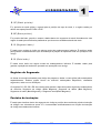
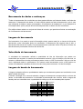
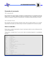
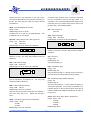
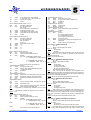
Registo de flags
O registo de flags é um registo de 16 bits, dos quais apenas 9 bits contêm flags, e que são usados
para indicar várias situações durante a execução das instruções bem como relativas ao seu
resultado.
--
--
--
--
O
D
I
T
S
Z
--
A
--
15
P
--
C
0
Figura 3 - Registo de flags do 8086.
Flag
Nome
O
Flag de Overflow
D
I
Flag de Direcção
Flag de Interrupção
T
Trap Flag
S
Z
Flag de Sinal
Flag de Zero
A
Flag de Carry Auxiliar
P
Flag de Paridade
C
Flag de Carry
Descrição
Qualquer resultado de uma operação aritmética sinalizada que exceda os limites da área destinada produz um
overflow OF=1
É usada para indicar a direcção em que as instruções de strings são processadas em relação a SI e DI
Quando a 1, habilita as interrupções INT externas, a 0 desabilita as mesmas
Quando a 1, após a próxima instrução ocorrerá uma interrupção passo a passo, é colocada a 0 pela própria
interrupção
É indicado se um número é positivo ou negativo.
É colocado a 0 se o resultado de uma operação aritmética ou lógica for 0
É utilizada pelas operações de ajuste decimal, reflecte o estado “vai um” entre os nibbles do byte inferior de um
resultado aritmético
Se o byte menos significativo do resultado de uma operação aritmética ou lógica apresentar um número par de
1’s, o bit é colocado a 1
Vai variando o seu valor de acordo com o resultado das instruções executadas, usado maioritariamente para
resultados de operações aritméticas e de comparação.
Tabela 1 - Descrição das flags do 8086.
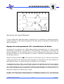
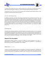
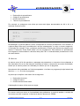
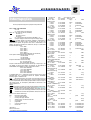
Organização da memória do 8086
O microprocessador 8086 tem um barramento de endereços de 20 bits, assim pode endereçar até
220 bytes de memória (1 Mbyte). No entanto o 8086 não consegue trabalhar directamente com
endereços maiores do que 216 (palavras de 16 bits) pelo que, à partida, o seu funcionamento
estaria limitado a apenas 64 Kbytes de memória.
Para resolver este problema, o 8086 utiliza a memória de forma segmentada (blocos de
64 Kbytes), e para poder trabalhar com a memória disponível usando apenas registos de 16 bits, o
8086 recorre aos registos de segmento.
Assim para aceder a um endereço individualmente, utiliza 2 registos de 16 bits, o primeiro indica a
base do segmento (valor divisível por 16), e o segundo indica o offset dentro do segmento, assim
são designados por endereços relativos ou deslocamentos relativos.
Luís Miguel Charrua Figueiredo
1-7
E.N.I.D.H.
MICROPROCESSADORES
O
M I C R O P R O C E S S A D O R
8 0 8 6
1
FFFFFh
64 KB
Code Segment
XXXX0h
+Offset
Stack Segment
Segment
Register File
CS
SS
DS
ES
Data Segment
Extra Segment
00000h
Figura 4 - Mapa de memória exemplificativo dos segmentos e offset.
Uma base e um deslocamento formam um endereço segmentado, o 8086 converte o endereço
segmentado de 32 bits num endereço de 20 bits. Na realidade o que acontece é que o CPU
desloca a base 4 bits à esquerda e adiciona-lhe o valor de deslocamento.
ex.: o endereço 1666:0001 = 16660h+0001h=16661h
O espaço de memória do 8086 é implementado por dois bancos de memória de 512 Kbytes
independentes. Denominados por banco par e banco ímpar.
Os bits de endereço de A1 a A19 seleccionam e acedem a uma posição de memória, assim sendo,
estas linhas são aplicadas aos dois bancos em paralelo. A0 e BHE (Bank High Enable) são usadas
como sinais de selecção do banco, o valor ‘0’ em A0 identifica um endereço par de um byte de
dados e faz com que esse banco fique acessível. Por outro lado, o BHE a ‘0’ permite ao banco
impar ser acedido por um endereço impar de um byte de dados. Cada um dos bancos de memória
providência metade dos 16 bits de uma palavra de dados.
Quando o 8086 acede a uma palavra de dados de 16 bits num endereço par, os dois bancos são
acedidos ao mesmo tempo, tanto o A0 como o BHE estão no nível lógico ‘0’. Neste caso, um byte
de dados é transferido ou recebido pelo banco par e pelo banco impar simultaneamente. Esta
palavra de 16 bits é transferida pela linha de dados completa (D0 a D15). Quando a memória for
acedida por endereço par, diz-se que os bancos de memória estão alinhados, e as operações de
transferência fazem-se apenas num ciclo de bus.
Luís Miguel Charrua Figueiredo
1-8
E.N.I.D.H.
MICROPROCESSADORES
O
M I C R O P R O C E S S A D O R
Banco Par
8 0 8 6
1
Banco Impar
00004h
00005h
00002h
00003h
00000h
AA
BB
00001h
AABB
Figura 5 - Exemplo de uma transferência de memória com os bancos alinhados.
Se a palavra a aceder estiver num endereço ímpar, diz-se que os bancos estão desalinhados, isto
é, o byte mais significativo está localizado no endereço menor do banco impar, o byte impar da
palavra está localizado no endereço x+1 e o byte par está no endereço y, são necessários dois
ciclos de bus para aceder a esta palavra. No primeiro ciclo o byte impar que está localizado no
endereço x+1, é acedido colocando-se A0 a ‘1’ e BHE a ‘0’, e os dados são transferidos por D8 a
D15. logo se seguida, o 8086 incrementa o endereço (A0 a ’0’), isto representa que o próximo
endereço é par. De seguida inicia-se um segundo ciclo de memória, durante o qual o byte par,
localizado em y no banco par é acedido. A transferência é feita por D0 a D7 das linhas de dados,
sendo BHE ‘1’ e A0 ‘0’.
Banco Par
Banco Impar
00004h
00005h
00002h
00003h
BB
00000h
AA
00001h
BBAA
Figura 6 - Exemplo de transferência de memória com os bancos desalinhados.
Deste modo para se aceder a uma palavra de dados não alinhada o 8086 usa dois ciclos de bus,
tendo ainda de alinhar as palavras internamente (transparente para o utilizador).
AA
BB
AA
A25Fh
BB
A25Eh
Figura 7 - Forma de armazenamento de palavras na memória.
Para optimizar o desempenho do 8086 deve-se colocar as palavras de 16 bits em posições de
memória de endereço par, para que os bancos esteja alinhados, e para que ao aceder aos
mesmos se use apenas um ciclo de bus.
Luís Miguel Charrua Figueiredo
1-9
E.N.I.D.H.
MICROPROCESSADORES
O
M I C R O P R O C E S S A D O R
8 0 8 6
1
Ciclos de barramento
Cada ciclo de barramento do processador consiste em pelo menos quatro ciclos de clock. Estes
são conhecidos como T1, T2, T3 e T4. O endereço é colocado no bus pelo processador durante T1 e
a transferência de dados é feita durante T3 e T4. T2 é usado principalmente para a mudança de
direcção do bus durante operações de leitura.
No caso do dispositivo endereçado dar um sinal “NOT READY”, são inseridos estados de espera
(Wait States, Tw) entre T3 e T4. cada Tw inserido tem a duração de um ciclo de clock.
Podem existir períodos de inactividade entre ciclos de bus, estes são referidos como estados IDLE
(Ti), ou ciclos de clock inactivos, são usados pelo processador para processamento interno.
Durante T1 de qualquer ciclo de barramento surge um pulso de ALE (Address Latch Enable). No
final deste pulso o está disponível um endereço válido nas latches de endereço, bem como
algumas informações de status relativas ao ciclo de barramento actual.
Os bits S0 , S1 e S2 são usados no modo máximo pelo controlador do bus para identificar o tipo de
operação a ser executada de acordo com a tabela 2.
S2
S1
S0
Operação
0
0
0
0
1
1
1
1
0
0
1
1
0
0
1
1
0
1
0
1
0
1
0
1
Int. Acknowledge
Read I/O
Write I/O
Halt
Instruction Fetch
Read from Memory
Write to Memory
Passive (Idle State)
Tabela 2 - Tipos de ciclo do bus .
Os bits S3 a S7 são multiplexados com os bits menos significativos de endereços e com BHE ,
sendo válidos entre T2 e T4. S3 e S4 indicam que segmento de memória irá ser utilizado neste ciclo
de bus de acordo com a tabela:
S4
0
0
1
1
S3
0
1
0
1
Descrição
Extra Segment
Stack
Code or none
Data
Tabela 3 - Segmento de memória acedido.
O bit S5 é um espelho da flag IF, S6=0 e S7 é um bit de status de reserva.
Luís Miguel Charrua Figueiredo
1 - 10
E.N.I.D.H.
MICROPROCESSADORES
O
M I C R O P R O C E S S A D O R
8 0 8 6
1
Temporização do sistema
Ciclo de leitura (read cycle)
O ciclo de leitura começa em T1 e com o pulso de ALE. No flanco descendente de ALE, é usado
para fixar a informação de endereço na latch de endereços, que está disponível no bus. O BHE e
A0 endereçam os bytes mais significativos ou menos significativos ou ambos. De T1 a T4 a linha
M/IO indica se se trata de leitura de memória ou de um dispositivo de I/O.
Em T2 o endereço é removido do bus, ficando o mesmo em alta impedância. O sinal de leitura /RD
é também activado durante T2, este faz com que o dispositivo endereçado coloque os dados no
bus, e que active a linha READY com o valor ‘1’. Quando o processador colocar a linha RD a ‘1’ o
dispositivo endereçado coloca a sua saída em alta impedância.
T1
T2
T3
T4
CLK
M/IO
ALE
A15-AD0
A15-AD0
Data In
RD
Read
Cycle
DT/R
DEN
Figura 8 - Diagrama temporal de um ciclo de leitura.
Ciclo de escrita (write cycle)
O ciclo de escrita também começa em T1 com a activação da linha ALE e colocação do endereço
na latch. A linha M/IO é novamente activada para indicar o tipo de escrita (memória ou I/O). Em T2,
imediatamente a seguir ao endereço, o processador coloca os dados no bus, estes dados
permanecem disponíveis até ao meio de T4. Durante T2, T3 e TW o processador activa a linha WR .
O sinal WR é activado no inicio de T2, ao contrário de RD que tem um atraso para permitir
variações no bus.
Os sinais BHE e A0 são usados para seleccionar os bytes da palavra de memória I/O a serem
lidas ou escritas de acordo com a tabela 4.
Luís Miguel Charrua Figueiredo
1 - 11
E.N.I.D.H.
MICROPROCESSADORES
O
BHE
0
0
1
1
M I C R O P R O C E S S A D O R
A0
Descrição
0
1
0
1
Palavra completa
Byte mais significativo de/para endereço impar
Byte menos significativo de/para endereço par
Nenhum
8 0 8 6
1
Tabela 4 - Bytes da memória a ser acedidos.
Os portos I/O são endereçados da mesma forma que as localizações de memória. Bytes
endereçados em posições pares são colocados nas linhas D7-D0 do bus, e os endereços em
posições impares são colocados nas linhas D15-D8 do bus.
T1
T2
T3
T4
CLK
M/IO
ALE
A15-AD0
A15-AD0
Data In
Write
Cycle
WR
DEN
Figura 9 - Diagrama temporal de um ciclo de escrita.
Interrupções
Existem duas classes de interrupções no 8086, as de software e as de hardware. As de software
estão descritas no conjunto de instruções do 8086. As interrupções de hardware podem ser
divididos em “mascaráveis” e “não mascaráveis”.
As interrupções resultam na transferência de controlo para uma nova localização de programa,
através da utilização de uma tabela de 256 elementos contendo ponteiros com endereços para a
localização das rotinas de interrupção. Esta tabela está localizada nos endereços absolutos 000H a
3FFH, que é reservada para este fim.
Cada elemento da tabela tem 4 bytes e corresponde a um “tipo” de interrupção. Um dispositivo que
origine uma interrupção, “fornece” um número de 8 bits durante a rotina de “Interrupt Acknowledge”
e que é usado para ser “encaminhado” através da tabela de vectores de interrupção.
Luís Miguel Charrua Figueiredo
1 - 12
E.N.I.D.H.
MICROPROCESSADORES
O
M I C R O P R O C E S S A D O R
8 0 8 6
1
Interrupções não mascaráveis
O 8086 tem apenas um pino de interrupt não mascarável e que tem prioridade mais elevada que
os mascaráveis. Esta interrupção é activada no flanco ascendente.
A interrupção NMI deve ter uma duração mínima de 2 ciclos de clock, mas não é necessário que
esteja sincronizada com este. Na transição 0-1 deste pino, é activada a latch interna do
processador, e a interrupção será atendida no fim da instrução actual, ou entre movimentos de
instruções de bloco.
Interrupções mascaráveis (INTR)
O 8086 tem apenas uma entrada de interrupção mascarável (INTR). Que pode ser mascarada
(codificada) internamente por software.
Esta interrupção é activada por nível, e é internamente sincronizada com cada ciclo de clock no
seu flanco ascendente. Para ser atendida, deve estar a ‘1’ durante o último ciclo de clock do final
da instrução corrente, ou no final das instruções de movimento de bloco.
Durante a sequência de resposta a INTR, todas as outras interrupções são desabilitadas. E é feito
um reset ao bit de enable como resposta a qualquer interrupção (INTR, NMI, Software e singlestep), embora o registo de flags seja automaticamente colocado na stack, o mesmo reflicte o
estado do processador antes da interrupção, até que o registo de flags seja retirado da stack o bit
de enable fica a ‘0’, a não ser que seja alterado por software.
Durante a sequência de resposta (ver figura 10) o processador executa dois ciclos completos de
interrupt acknowladge (INTA). O processador activa a linha LOCK no T2 do primeiro ciclo de bus,
até ao T2 do segundo.
Um pedido de HOLD do bus não será atendido até ao fim do segundo ciclo de INTA. Durante o
segundo ciclo de bus é lido um byte do sistema externo de interrupt (ex.: 8259A PIC) que identifica
o tipo e origem da interrupção. Este valor é utilizado para apontar o controlo de programa para a
rotina apropriada através da tabela de vectores de interrupção.
Enquanto a linha INTR estiver a ‘1’, o processador continua a responder a esses pedidos de
interrupção. No fim da rotina de interrupção as flags originais são retiradas da stack e colocadas no
registo de flags.
Luís Miguel Charrua Figueiredo
1 - 13
E.N.I.D.H.
MICROPROCESSADORES
O
T1
T2
T3
M I C R O P R O C E S S A D O R
T4
TI
T1
T2
T3
8 0 8 6
1
T4
ALE
LOCK
INTA
Float
AD0,AD15
Type Vector
Figura 10 - Diagrama temporal da sequência de Interrupt Acknowledge.
Sistema de Input/Output
A forma utilizada pelo 8086 para aceder a dispositivos I/O é semelhante à usada para aceder à
memória principal, ou seja, estas transferências são feitas através do barramento multiplexado de
dados e endereços.
Espaço de endereçamento I/O e transferência de dados
As portas I/O num sistema com o 8086 podem transferir informação de 8 ou 16 bits. A porta
seleccionada é acedida por um endereço I/O. Este endereço é especificado na instrução que
executa operações I/O. Os endereços são de 16 bits e aparecem nas linhas AD0 a AD15 do
barramento. Os bits A16 a A19 são colocados a ‘0’ durante T1 (período de endereçamento) de todos
os ciclos de I/O do bus.
Através do sinal de controlo M/IO , o CPU informa o circuito externo que o endereço no barramento
é para uma porta de I/O, desta forma este sinal pode ser usado para a latch de endereços ou
descodificador externo. O espaço dedicado aos dispositivos é de 64 Kbytes.
As transferências entre o CPU e os dispositivos externos são realizadas através do bus de dados,
a transferência de dados (palavras de 16 bits) requerem um a dois ciclos de bus. Para assegurar
que é usado apenas um ciclo, as portas de I/O deverão estar alinhadas nos endereços pares. Por
outro lado, as transferências de palavras de 8 bits necessitam de apenas um ciclo de bus, quer os
dispositivos estejam num endereço par ou ímpar.
No 8086 a transferência de endereços pares são realizadas nas linhas D0 a D7 e as impares nas
linhas D8 a D15. para aceder sequencialmente a um dispositivo periféricos (I/O), este deve estar
Luís Miguel Charrua Figueiredo
1 - 14
E.N.I.D.H.
MICROPROCESSADORES
O
M I C R O P R O C E S S A D O R
8 0 8 6
1
ligado de modo a que estejam todos em endereços pares ou impares. desta forma, todas as
transferências terão lugar na mesma parte da via de dados.
I/O por mapeamento de memória
Os dispositivos de I/O também podem ser alocados no espaço de memória do 8086. Devido ao
facto de os dispositivos actuarem como um endereço de memória, o CPU verá os dispositivos
como posições de memória e não saberá distinguir as duas situações.
Esta técnica de mapeamento de I/O de memória proporciona flexibilidade de programação.
Qualquer instrução que referência a memória pode ser usada para aceder a uma porta I/O
localizada no espaço de memória.
Por exemplo a instrução MOV pode transferir dados entre uma porta lógia e um registo, ou as
instruções AND, OR e TEST poderão ser usadas para manipular directamente os bits dos registos
dos dispositivos I/O (porque estes se apresentam como posições de memória), além disso, I/O em
memória mapeada apresenta a vantagem de poder utilizar os vários modos de endereçamento do
processador (apenas disponíveis para endereços de memória).
Luís Miguel Charrua Figueiredo
1 - 15
E.N.I.D.H.
MICROPROCESSADORES
A R Q U I T E C T U R A
D O S
M I C R O C O M P U T A D O R E S
2
Arquitectura dos Microcomputadores
A evolução dos microcomputadores
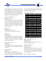
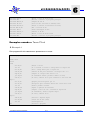
Na tabela podemos ver a evolução da família de microprocessadores INTEL desde a introdução do
microprocessador de 16 bits até ao PENTIUM III de 1 GHz.
A utilização de microcomputadores de 16 bits começa por ser generalizada por volta de 1980 com
o lançamento do primeiro computador pessoal por parte da IBM, tendo ficado conhecido como o
IBM-PC. Embora já nessa altura outras marcas fabricassem equipamentos de 16 bits baseados no
8086, estes não eram compatíveis entre si, quer no sistema operativo, quer no software que
podiam executar.
O equipamento lançado pela IBM, embora seja construído tendo por base um microprocessador
cujo bus é de 8 bits, o 8088, transformou-se no padrão dos computadores pessoais de 16 bits,
tanto para o mercado das empresas que desenvolviam software, como para os fabricantes de
hardware.
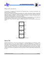
Modelo
Ano de lançamento Velocidade Bus de dados Espaço de memória endereçável
5 MHz
8086
1978
8 MHz
16 bits
1 Mbyte
10 MHz
8088
5 MHz
e
1979
8 MHz
8 bits
1 Mbyte
V20
10 MHz
8 MHz
80286
1982
10 MHz
16 bits
16 Mbyte
12 MHz
16 MHz
20 MHz
80386 DX
1985
32 bits
4 Gbyte
25 MHz
33 MHz
16 MHz
80386 SX
1988
16 bits
16 Mbyte
20 MHz
25 MHz
80486 DX
1989
33 MHz
32 bits
4 Gbyte
50 MHz
16 MHz
20 MHz
80486 SX
1991
25 MHz
32 bits
4 Gbyte
33 MHz
50 MHz
60 MHz
66 MHz
75 MHz
90 MHz
64 bits
4 Gbyte
100 MHz
Pentium
1993
120 MHz
133 MHz
150 MHz
166 MHz
150 MHz
Pentium – Pro
1995
64 bits
16 Gbyte
180 MHz
Luís Miguel Charrua Figueiredo
2-1
E.N.I.D.H.
MICROPROCESSADORES
A R Q U I T E C T U R A
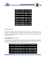
Pentium II
1997
Celeron
1998
Pentium III
1999
Pentium IV
2000
D O S
200 MHz
233 MHz
350 MHz
400 MHz
450 MHz
233 MHz
266 MHz
333 MHz
466 MHz
533 MHz
450 MHz
500 MHz
550 MHz
1.3 GHz
1.4 GHz
1.5 GHz
1.7 GHz
M I C R O C O M P U T A D O R E S
64 bits
16 Gbyte
64 bits
4 Gbyte
64 bits
16 Gbyte
64 bits
64 Gbyte
2
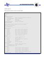
Tabela 5 - Resumo da evolução dos microprocessadores.
Isto permitiu normalizar o mercado e compatibilizar os equipamentos, para que fosse possível a
troca de informação entre máquinas de diferentes fabricantes.
A escolha do 8088 por parte da IBM, foi apenas numa perspectiva financeira, pois tratava-se de um
processador mais barato, tornando o equipamento mais atractivo ao mercado jovem, uma vez que
naquela altura a velocidade não era um dos factores mais importantes na escolha de um
computador.
A família 80x86
Iremos apenas falar das principais características de alguns dos microprocessadores da família
80x86 da Intel.
O 8088
Este processador difere do 8086 apenas no facto do seu bus de dados ser de 8 bits (o CPU é de
16 bits, as transferências de palavras de 16 bits são feitas em dois ciclos) e a queue que é de
apenas 4 bytes, o que o torna mais lento que o 8086.
O 80186/88
O 80186 e 80188 tem entre eles as mesmas diferenças que o 8088 e 8086 (o 80186 tem bus de
dados a 16 bits enquanto o 80188 tem bus de dados de 8 bits). O 80186/8 não é apenas um
microprocessador, uma vez que já integra o controlador de interrupções, o controlador DMA e um
timer, tem também um maior número de instruções que o 8086, e foi optimizado para maior
rapidez.
Luís Miguel Charrua Figueiredo
2-2
E.N.I.D.H.
MICROPROCESSADORES
A R Q U I T E C T U R A
D O S
M I C R O C O M P U T A D O R E S
2
O 80286
O 80286 é um processador de 16 bits, com um bus de endereços de 24 bits, e o bus de dados de
16 bits. A sua inovação tecnológica deve-se ao facto de poder funcionar em modo protegido, no
qual pode endereçar até 16 Mbytes de memória, em modo real funciona como o 8086.
Para funcionar em modo protegido, tem mais 5 registos que não existiam no 8086. Tem
endereçamento com pipeline, transfere novo endereço um ciclo de clock antes de terminar a
operação actual.
O 80386
O 80386 foi o primeiro microprocessador de 32 bits a ser usado em PC’s e as suas principais
características são:
- 132 Pinos;
- Queue de 16 bytes;
- Unidade de gestão de memória (MMU) com segmentação e unidade de paginação;
- Bus de dados e endereços de 32 bits;
- Capacidade de endereçamento físico de 4 Gbytes;
- Implementação dos modos real, protegido e virtual 8086;
- Tem a mais 4 registos de controlo para o modo protegido, e 8 registos de debug para
suporte de debugging no modo protegido e modo virtual 8086 a nível de hardware.
O 80486
O 486 consiste num processador 386 melhorado, com em melhor coprocessador matemático e um
chip de memória cache de 8 Kbytes, para código e dados.
O Pentium
As suas características principais são:
-
Dois pipelines de inteiros e um floating-point, que em determinadas circunstâncias
conseguem executar duas instruções no mesmo ciclo de clock;
Duas caches separadas (uma para código e outra para dados) com 8 Kbytes cada;
Bus de dados externo de 64 bits;
É um processador de 32 bits;
Tem 296 pinos.
Luís Miguel Charrua Figueiredo
2-3
E.N.I.D.H.
MICROPROCESSADORES
A R Q U I T E C T U R A
D O S
M I C R O C O M P U T A D O R E S
2
O Pentium-Pro
-
Tem 387 pinos;
Duas caches separadas para código e dados no CPU e uma cache adicional para código e
dados ligada directamente a CPU, com capacidade de 256 Kbytes ou 512 Kbytes;
Bus de endereços de 32 bits, para endereçamento físico de 64 Gbytes.
Multiprocessamento com até 4 CPU’s sem lógica adicional.
O Pentium II
O Pentium II é um Pentium-Pro ao qual foi adicionada a tecnologia MMX.
A tecnologia MMX já existia no Pentium.
MMX significa Multimédia Extension, e aumenta a velocidade das aplicações multimédia e 3D.
A principal característica deste tipo de aplicações multimédia e 3D é que são programas em que
uma grande quantidade de pequenos pacotes de dados tem de ser processados (manipulação de
bits numa imagem 3D por exemplo).
A arquitectura MMX permite recolher uma série de pacotes de dados e processar uma mesma
instrução em todos dados ao mesmo tempo (SIMD Single Intruction Multiple Data).
O Pentium III
É um desenvolvimento do Pentium II em que as inovações de resumem essencialmente a 72
novas instruções, que elas próprias constituem uma versão melhorada e estendida do MMX.
O Atlhon / K7 da AMD
-
Velocidade de 500 MHz a 1 GHz
Três pipelines de inteiros independentes
Três pipelines para cálculo de endereços independentes
Cache de 128 Kbytes no chip do processador
Cache de 512 Kbytes ligada directamente ao CPU
Luís Miguel Charrua Figueiredo
2-4
E.N.I.D.H.
MICROPROCESSADORES
A R Q U I T E C T U R A
D O S
M I C R O C O M P U T A D O R E S
2
Compatibilidade entre microprocessadores
Cada novo processador acrescenta inovações tecnológicas em relação ao seu antecessor, mas
não perde compatibilidade com os anteriores, incluindo o 8086.
Modo real, Protegido e Virtual 8086
Modo real
Modo de endereçamento do 8086. Multiplica o valor do registo de segmento por 16, o que é
equivalente a deslocar o valor de 4 bits para a esquerda, e adiciona o valor do registo de offset. O
resultado é um valor de 20 bits, o que faz com que o espaço físico de endereçamento seja limitado
a 1 Mbyte.
Modo Protegido
Foi originalmente implementado no 80286 para proteger os acessos inválidos e incorrectos às
diferentes tarefas num sistema operativo multitarefa (OS/2, Linux, Windows NT, Windows 2000).
Para conseguir isso, o hardware do processador verifica os acessos aos dados e ao código feito
por um programa e utiliza 4 níveis de privilégios para fornecer direitos de acesso.
O cálculo do endereço de memória no modo protegido também é diferente: o registo de segmento
age como um selector para extrair um endereço de 32 bits da memória e adiciona-o ao offset de
16 bits. O valor do segmento não é um endereço, mas representa um índice numa tabela de
endereços de segmento. Cada entrada dessa tabela contém um endereço de 24 bits, que - esse
sim - indica o início do segmento da memória. Pode endereçar até 16 Mbytes de espaço físico
(224 bytes).
No 80386 o modo foi melhorado ao permitir endereços de segmento e de offset de 32 bits,
possibilitando endereçar até 4 Mbytes.
Modo virtual 8086
Foi introduzido com o 80386, o endereçamento é igual ao 8086, mas os endereços físicos de
1 Mbyte são mapeados para qualquer zona dos 4 Gbytes disponíveis. Isto permite que um sistema
operativo multitarefa execute vários programas feitos para o 8086, cada um com o seu espaço de
1 Mbyte independente. O modo virtual 8086 surgiu porque na altura do aparecimento do 80386,
ainda havia muitos programas a correr sobre o MS-DOS, que é um sistema operativo em modo
real. O modo virtual 8086 é usado, por exemplo, por uma janela de DOS a correr sobre o Windows.
Luís Miguel Charrua Figueiredo
2-5
E.N.I.D.H.
MICROPROCESSADORES
A R Q U I T E C T U R A
D O S
M I C R O C O M P U T A D O R E S
2
Barramentos dos computadores
Os PC’s têm vários barramentos (muitos dos PC’s mais recentes têm pelo menos 4 barramentos),
é comum utilizar-se a designação de hierarquia de barramentos.
Estes permitem a interligação dos vários componentes do PC, com uma estrutura de interligação
entre si de forma hierárquica, à medida que vamos descendo na hierarquia dos barramentos,
menores são as velocidades de funcionamento dos mesmos.
Bus do processador
É o bus de mais alto nível, e é o que utiliza o chipset (conjunto de circuitos que em conjunto com o
processador controla todo o hardware) para enviar e receber os dados de e para o processador.
Bus de cache
Utilização de um bus dedicado para aceder à memória cache. Também aparece na literatura como
Backside Bus.
Bus de memória
É o primeiro bus de segundo nível que permite a ligação de memória ao chipset e processador.
Local Bus I/O
É um barramento de I/O de alta velocidade utilizado para ligar periféricos à memória, chipset e ao
processador. Por exemplo as placas de vídeo, para armazenamento de dados, interfaces de rede a
alta velocidade, os barramentos mais comuns para I/O local são os VESA (Video Electronics
Standard Association Local Bus) e o (PCI) (Peripherical Interconnect Bus).
Bus standard de I/O
É o barramento ISA (Industry Standards Association), presente desde o primeiro PC e é usado
para ligações de periféricos que não exijam velocidades muito altas, ratos, modems, placas de
som, placas de rede de baixa velocidade.
O chipset é que coordena todas estas comunicações, e garante a perfeita comunicação entre
todos eles. Os Novos PC usam um barramento adicional, projectado unicamente para interfaces
gráficas, aparece na Motherboard como um slot AGP (Accelerated Graphics Port), não deverá ser
entendido como um barramento mas sim como um porto (porque apenas se pode ligar um
dispositivo nessas linhas.
Luís Miguel Charrua Figueiredo
2-6
E.N.I.D.H.
MICROPROCESSADORES
A R Q U I T E C T U R A
D O S
M I C R O C O M P U T A D O R E S
2
Barramento de dados e endereços
Todos os barramentos são constituídos por duas partes distintas: as linhas de dados e as linhas de
endereços. O barramento de dados é o mais referido quando se fala de barramentos, pois é este
que transporta os dados a serem processados. O barramento de endereços é o que transporta a
informação sobre qual a posição de memória de/para onde os dados vão ser transferidos.
Em adição existem ainda um conjunto de linhas de controlo, que permitem efectuar a coordenação
do funcionamento do barramento.
Largura do barramento
Um barramento é um canal no qual a informação circula, quanto maior for o número de linhas do
barramento, mais informação pode ser transferida. O barramento ISA original tinha 8 bits, o
barramento ISA actual tem 16 bits. Os outros barramentos (incluindo VLB e PCI) são de 32 bits. Os
barramentos do processador Pentium são de 64 bits.
Velocidade do barramento
A velocidade do barramento reflecte a quantidade de bits de informação que podem ser
transmitidos por segundo. A maioria dos barramentos transmite 1 bit por linha por ciclo de clock, no
entanto os barramentos de alta performance podem como no AGP movimentar 2 bits por ciclo de
clock, duplicando assim a performance. Do mesmo modo barramentos como a ISA podem em
certas circunstâncias necessitar de dois ciclos de clock para movimentar 1 bit de informação.
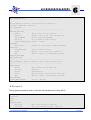
Largura de banda do barramento
A largura de banda reflecte a quantidade de dados que teoricamente podem ser transferidos numa
dada unidade de tempo.
Fazendo a analogia com uma auto-estrada, a largura do barramento corresponderá ao número de
faixas, a velocidade do barramento à velocidade de deslocação dos veículos, então a largura de
banda pode ser entendida como a quantidade de tráfego que a auto-estrada pode suportar.
Largura Velocidade Largura de Banda
(bits)
(MHz)
(Mbytes/s)
ISA
8
8.3
7.9
ISA Plug & Play
16
8.3
15.9
EISA
32
8.3
31.8
VLB
32
33.3
127.2
PCI
32
33.3
127.2
PCI 2.1
64
66.6
508.6
AGP
32
66.6
254.3
AGP (2x Mode)
32
66.6x2
508.6
AGP (4x Mode)
32
66.6x4
1017.3
Barramento
Tabela 6 - Comparação entre os diversos barramentos.
Luís Miguel Charrua Figueiredo
2-7
E.N.I.D.H.
MICROPROCESSADORES
A R Q U I T E C T U R A
D O S
M I C R O C O M P U T A D O R E S
2
A tabela mostra a largura de banda teórica que alguns dos barramentos I/O podem suportar hoje
em dia. De notar que os barramentos podem trabalhar a diferentes velocidades. A largura de
banda do PCI standard deveria ser de 133, ou seja 32 / 8 x 33.3 = 133.3 Mb/s, como muitas vezes
é referenciado. No entanto isto não é tecnicamente correcto, porque 1 MHz = 1000000 Hz, mas
1 Mb = 1046576 bytes assim a largura de banda do PCI é 127,2 Mbytes/s.
Interface de barramento
Num sistema onde existem muitos barramentos distintos, devem ser previstos circuitos pelo
chipset para interligar os barramentos e permitir aos diferentes dispositivos comunicar entre eles.
Estes dispositivos são chamados BRIDGES, assim existe a PCI-ISA Brigde, que faz parte do
sistema do chipset num Pentium ou Pentium-Pro. O barramento PCI também tem uma bridge para
o barramento do processador.
Os diversos tipos de barramentos
Como já foi mencionado anteriormente, existem diversos tipos de barramentos num PC, iremos
agora descrever as principais características de alguns dos mais comuns.
O Barramento ISA
ISA é a abreviatura de Industrial Standard Architecture e define um standard obrigatório para todos
os fabricantes, estipulando entre outros as características do bus dos slots de expansão. Este bus
funciona a 8,33 MHz, limitado pelo sobreaquecimento que os componentes usados aquando da
definição do standard ISA.
Luís Miguel Charrua Figueiredo
2-8
E.N.I.D.H.
MICROPROCESSADORES
A R Q U I T E C T U R A
D O S
M I C R O C O M P U T A D O R E S
2
Figura 11 - Diagrama da arquitectura ISA de um XT.
A arquitectura EISA (Extended ISA)
Com a introdução dos microprocessadores de 32 bits, com barramentos de 32 bits, foi necessário
estender também o bus ISA. Daí resultou o bus EISA, que mantém a compatibilidade com o
sistema ISA. Desta forma, pode-se incorporar componentes ISA em slots EISA sem problemas. O
bus EISA também está limitado a uma frequência máxima de 8,33 MHz, e tem um controlador que
lhe permite identificar se uma placa é ISA ou EISA e comunicar com ela de acordo com o seu tipo.
A informação de configuração das placas EISA é armazenada numa CMOS estendida de 4 Kbytes
para este fim. Programas de instalação especiais fornecem suporte para configuração das placas
EISA, e automaticamente escrevem dados no CMOS estendidos. A informação típica guardada
são quais os portos de I/O utilizados pela placa, que linhas de IRQ e DMA lhe estão atribuídas.
Luís Miguel Charrua Figueiredo
2-9
E.N.I.D.H.
MICROPROCESSADORES
A R Q U I T E C T U R A
D O S
M I C R O C O M P U T A D O R E S
2
Figura 12 - diagrama de blocos de um microcomputador com arquitectura EISA.
Nos que requerem taxas de transmissão muito altas (placas gráficas, e discos rígidos) os 8 MHz do
bus EISA rapidamente se tornam insuficientes. Com o conceito de bus local, tentou-se colocar o
bus desses componente a trabalhar à mesma velocidade do CPU.
A Intel desenvolveu o bus PCI e o comité VESA desenvolveu o VLBus. Eles foram introduzidos
independentemente, e são ambos standards de bus local.
O bus local VESA (VLB)
O VLB representa uma expansão dos sistemas ISA/EISA e funciona à mesma frequência do
processador. Está ligado directamente ao bus local do CPU de um 80386, 80486 ou Pentium. O
VLB está situado entre o sistema processador/memória e o bus de expansão standard. O
controlador do subsistema VLB gera todos os sinais necessários (endereços, dados e controlo), e
regula todo o funcionamento do bus.
Usando slots de expansão, o VLB pode funcionar a uma frequência máxima de 50 MHz, sem slots
de expansão pode funcionar a frequências até 66 MHz.
É incluído apenas um contacto de interrupção na especificação do VLB (IRQ9), que está ligado
directamente à linha IRQ9 do bus (E)ISA. Normalmente o VLB também utiliza o slot (E)ISA
existente, pelo que estão disponíveis linhas de interrupção suficientes.
O VLB suporta uma área de endereços I/O de 64 Kbytes para portos de 8, 16 e 32 bits. Não
implementa DMA.
Luís Miguel Charrua Figueiredo
2 - 10
E.N.I.D.H.
MICROPROCESSADORES
A R Q U I T E C T U R A
D O S
M I C R O C O M P U T A D O R E S
2
Figura 13 - Diagrama de blocos de um microcomputador com arquitectura VLB.
O barramento PCI
O PCI é hoje em dia a solução standard para PC’s, e tem a seguinte estrutura.
Luís Miguel Charrua Figueiredo
2 - 11
E.N.I.D.H.
MICROPROCESSADORES
A R Q U I T E C T U R A
D O S
M I C R O C O M P U T A D O R E S
2
Figura 14 - Diagrama de blocos de um microcomputador com arquitectura PCI.
A bridge PCI representa a ligação entre o sistema CPU/RAM e o bus PCI. Todas as unidades
individuais estão ligadas ao bus PCI, e ao contrário do VLB estas unidades podem ser integradas
na mainboard, mas na maioria dos casos são construídas como adaptadores.
A interface do bus de expansão é um outro tipo de unidade PCI. Com ela é possível ter um sistema
de bus (E)ISA ou outro ligado ao bus PCI, sendo assim como mais uma unidade PCI. No total é
possível ter no máximo dez unidades PCI ligadas ao bus PCI.
Tal como no 8086, as linhas são multiplexadas entre dados e endereços, poupando no número de
linhas, mas diminuindo a velocidade de funcionamento.
O PCI inclui uma área de endereços de configuração. É utilizada para aceder aos registos de
configuração e memória de configuração de cada unidade PCI. A memória de configuração é cerca
de 256 bytes para cada unidade PCI.
Desde que o CPU não esteja a aceder a nenhuma unidade PCI, a ligação do sistema CPU/RAM e
do bus PCI através da bridge PCI é suficientemente poderosa para permitir que a bridge e o CPU
operem em paralelo. Desta forma, é possível trocar dados entre duas unidades PCI, através da
bridge PCI, enquanto o processador está a realizar outras operações.
Ao contrário dos sistema (E)ISA, o bus PCI não implementa DMA.
Luís Miguel Charrua Figueiredo
2 - 12
E.N.I.D.H.
MICROPROCESSADORES
A R Q U I T E C T U R A
D O S
M I C R O C O M P U T A D O R E S
2
O sistema PCI suporta Plug & play, sendo normalmente é a BIOS que se encarrega de fazer a
atribuição das interrupções, sendo que o PCI normalmente suporta partilha de interrupções.
Os portos de I/O num PC com um bus PCI, estão todos localizados abaixo dos 64 Kbytes e a sua
utilização é semelhante à dos sistemas (E)ISA.
O bus ISA Plug & Play
As placas de expansão PCI foram uma grande inovação por serem dispositivos Plug & Play, que
são configurados automaticamente por uma BIOS Plug & Play. Quando o PCI emergiu, o bus ISA
era ainda o sistema de bus dominante e muitas placas de expansão ainda não tinham disponíveis
versões PCI (isso continua a acontecer ainda hoje com placas mais sofisticadas). Por esta razão, a
Intel e a Microsoft desenvolveram a ISA Plug & Play, de forma a dar às placas ISA um mecanismo
de configuração automático. O ISA Plug & Play da Intel e Microsoft é um standard que requer
hardware especializado nas placas individuais e um sistema operativo que suporte uma BIOS
Plug & Play.
O Chipset
Uma das mais importantes decisões a tomar por alguém que pretenda construir um PC é a escolha
do processador, logo seguida pelo chipset que o vai controlar. A chave para tomar esta decisão é a
velocidade do processador, e em particular o chipset que vai controlar o sistema. Normalmente um
chipset é projectado para trabalhar com um tipo específico de processador, em geral a maior parte
dos chipsets só suporta um processador, ou seu equivalente (Ciryx, AMD).
Suporte de velocidade
Processadores rápidos requerem circuitos de controlo do chipset capazes de os servir. A
especificação da velocidade do processador é feito utilizando dois parâmetros: a velocidade do
barramento de memória e o multiplicador do processador.
Memória cache
A cache é um buffer de memória entre o processador e a memória convencional. A existência de
cache permite ao processador fazer o seu trabalho enquanto espera dados da memória. Existem
vários níveis de cache (ou camadas de memória cache), quando se refere simplesmente à cache
Luís Miguel Charrua Figueiredo
2 - 13
E.N.I.D.H.
MICROPROCESSADORES
A R Q U I T E C T U R A
D O S
M I C R O C O M P U T A D O R E S
2
sem qualquer qualificador, estamos a falar da cache de nível 2 e refere normalmente a cache
colocada entre o processador e a memória.
Quando apareceram os PC’s o processador trabalhava a 8 MHz tal como todos os outros
dispositivos. Com o desenvolvimento da tecnologia, a velocidade dos processadores aumentou
muito, sem que este aumento tenha sido acompanhado pelos outros dispositivos (o aumento de
velocidade dos outros dispositivos foi bastante menor do que a dos processadores). O papel da
cache é minimizar os efeitos da disparidade de velocidade entre o processador e os outros
dispositivos.
Níveis de cache
Existem vários níveis de cache, cada nível que está mais próximo do processador é mais rápido
que o anterior, cada camada também faz caching da anterior.
Nível
Nível 1
Nível 2
RAM
Dispositivos “cached”
Cache Nível 2, RAM, HD/CD-ROM
RAM, HD/CD-ROM
HD/CD-ROM
Tabela 7 - Níveis de cache.
O que acontece em termos gerais é que quando o processador requer uma informação requer uma
informação, vai procurar, em primeiro lugar, na cache de nível 1; se não encontrar a informação
pretendida, vai então procurar na cache de nível 2, e se aí também não a encontrar, vai aceder à
RAM ou dispositivos.
Controladores
Usados para o controlo de periféricos e para executar tarefas que os processadores não estão
habilitados, o que possibilita ao processador concentrar-se noutras tarefas. Os controladores
seguintes são os inicialmente usados na construção dos PC’s.
Controlador DMA 8237
O DMA (Direct Memory Access) é uma técnica que permite a transferência de dados directamente
da memória para um dispositivo e vice-versa sem intervenção do CPU. Este método parece
bastante mais rápido que o tradicional em que os dados fazem a circulação através do CPU.
Actualmente a utilização da técnica DMA já não é considerada nas mesmas circunstâncias iniciais,
pois o DMA está directamente ligada com a velocidade do bus, e actualmente os processadores
são bastante mais rápidos que o bus. Com os PC’s de hoje em dia que trabalham a velocidades de
pelo menos 5 vezes mais altas que o bus, não parece lógico que possam beneficiar destes
mecanismos de DMA.
Luís Miguel Charrua Figueiredo
2 - 14
E.N.I.D.H.
MICROPROCESSADORES
A R Q U I T E C T U R A
D O S
M I C R O C O M P U T A D O R E S
2
Controlador de Interrupções
O controlador de interrupções é importante para o controlo de dispositivos externos tais como o
teclado, rato, discos rígidos ou portas série. Usualmente os processadores escrutinavam
periodicamente os periféricos para verificar a existência de dados a transferir. Nos PC’s ao
contrário do processador estar continuamente a efectuar polling nos dispositivos, são os
dispositivos que solicitam ao processador por meio de uma linha de interrupção, assim aquando do
pedido de interrupção o processador pára a execução da rotina corrente, e executa o atendimento
desse pedido de interrupção, isto é importante pois o processador somente é chamado quando
efectivamente é necessário.
De qualquer modo, o processo de verificar o pedido de interrupção pára o funcionamento corrente
e irá executar a rotina de serviço à interrupção e é um processo dispendioso de tempo, pelo que
surgiu a necessidade de implementar um dispositivo específico para o efeito, que faça o
atendimento do pedido de interrupção numa primeira fase, e só depois o indique ao processador.
O controlador de interrupções usado é o 8259, que permite o atendimento de 8 pedidos de
interrupção externos, seleccionar as prioridades de modo a definir se uma interrupção pode ou não
ser atendida primeiro que outra no caso de haver um pedido simultâneo. O PC inicial tinha 8 linha
de interrupt, nos nossos dias tem 15 através da utilização de dois 8259 em cascata, ou seja o
primeiro atende os pedidos do segundo tal como o processador atende os pedidos do primeiro.
Expansor de portos I/O
O expansor de porto 8255 permite a criação de ligações entre o processador e os periféricos, tais
como o altifalante e o teclado. Funciona como um interface que é utilizado pelo processador para a
ligação de portos I/O pois o processador não disponibiliza directamente estes portos I/O.
O temporizador 8253
O temporizador pode funcionar como contador de eventos ou como contador de tempo. Este
dispositivo transmite pulsos com tempo preciso dependendo da sua especificação, tem três
contadores de 16 bits independentes em que cada uma delas tem funções pré-definidas, uma linha
vai para o altifalante da máquina (usada para gerar a frequência dos sinais sonoros), e outra para o
controlador de interrupções (IRQ8). Outro tipo de controlador de relógio que também e muito usado
é o 8248.
Luís Miguel Charrua Figueiredo
2 - 15
E.N.I.D.H.
MICROPROCESSADORES
A R Q U I T E C T U R A
D O S
M I C R O C O M P U T A D O R E S
2
Mapa de memória
Os primeiros 10 segmentos de memória são reservados para a memória convencional, com
tamanho limitado a 640 Kbytes.
Os primeiros 64 Kbytes são bastante importantes pois contêm informações relativas à máquina e
rotinas de sistema. O segmento seguinte à memória convencional indica uma placa de vídeo EGA
(Enahnced Graphics Adapter) ou VGA (Video Graphics Adapter) e contem informações sobre a
memória de vídeo para gerar os vários modos gráficos.
O segmento de memória B é reservado para os adaptadores monocromáticos ou CGA (Computer
Graphics Adapter). Estes partilham o mesmo segmento de memória RAM de vídeo.
O segmento C até ao resto do 1 Mbyte é utilizado pela BIOS e outras expansões existentes da
BIOS.
FFFFFh
BIOS
E0000h
DFFFFh
Exoanded
ROM
C0000h
BFFFFh
Adaptor
Display
A0000h
9FFFFh
RAM
00000h
Figura 15 - Mapa de memória de um microcomputador.
Portos I/O
É através dos portos I/O, que se faz o interface entre o microprocessador e os periféricos, é nesta
área de memória de I/O que estão mapeados os diferentes dispositivos e controlador. O
processador vê estes dispositivos como se fossem posições de memória. Para aceder a esta zona
de memória, o processador dispõe de um espaço de endereçamento de 16 bits, pelo que o espaço
máximo endereçável é de 64 Kbytes, são ainda usadas linhas específicas de controlo para aceder
a esta zona de memória. Na tabela 8 mostra-se a posição de vários componentes relativamente ao
XT e AT.
Luís Miguel Charrua Figueiredo
2 - 16
E.N.I.D.H.
MICROPROCESSADORES
A R Q U I T E C T U R A
D O S
M I C R O C O M P U T A D O R E S
Componente
Controlador DMA (8237A-5)
Controlador de Interrupções
Temporizador
PPI 8255A-5
Teclado
Relógio em tempo real (MC 1468818)
DMA Registo de página
2º Controlador de Interrupções
Co-Processador Matemático
Co-Processador Matemático
Controlador de disco rígido
Porto de Jogos
Vago para expansão
2ª Porta Paralela
2ª Porta Série
Placa Protótipo
Placa de Rede
1ª Porta Paralela
Adaptador de vídeo monocromático
Adaptador CGA
Controlador de disco
1ª Porta Série
XT
000-00F
020-021
040-043
060-063
080-083
320-32F
200-20F
210-217
2F8-2FF
300-31F
378-37F
3B0-3BE
3D0-3DF
3F0-3F7
3F8-3FF
2
AT
000-01F
020-03F
040-05F
060-06F
070-07F
080-09F
0A0-0BF
0F0-0F1
0F8-0FF
1F0-1F8
200-207
278-27F
2F8-2FF
300-31F
360-36F
378-37F
3B0-3BE
3D0-3DF
3F0-3F7
3F8-3FF
Tabela 8 - Mapeamento de memória de portos I/O.
Interrupções
Interrupções de hardware são produzidas por vários dispositivos e filtradas através de um
controlador de interrupções para o processador. São possíveis 15 linhas de interrupção, estas
linhas são designadas IRQ0 a IRQ15, e correspondem como se pode ver na tabela às interrupções
08H a 0FH e da 70H a 77H.
Interrupções de software
As interrupções podem ser chamadas por software. Assim para se executada uma rotina da BIOS
ou DOS, não é necessário saber qual a localização da correspondente rotina. Rotinas essas que
são chamadas invocando apenas a interrupção correspondente.
Int Nº
00h
01h
02h
03h
04h
05h
06h
07h
08h
09h
0Ah
0Bh
0Ch
Address
0000h-0003h
0004h-0007h
0008h-000Bh
000Ch-000Fh
0010h-0013h
0014h-0017h
0018h-001Bh
001Dh-001Fh
0020h-0023h
0024h-0027h
0028h-002Bh
002Ch-002Fh
0030h-0033h
Luís Miguel Charrua Figueiredo
Descrição
Processor – Division by zero
Processor – Single step
Processor – NMI
Processor – Breakpoint reached
Processor – Numeric overflow
Hardcopy
Unknown instruction (80286)
Reserved
IRQ0: Timer (call 18.2 times/sec)
IRQ1: Keyboard
IRQ2: 2nd 8259 (AT only)
IRQ3: Serial Port 2
IRQ4: Serial Port 1
Int Nº
22h
23h
24h
25h
26h
27h
28h
29h-2Eh
2Fh
30h-32h
33h
34h-40h
41h
2 - 17
Address
Descrição
0088h-008Bh Address of DOS quit program routine
008Ch-008Fh Address of DOS Ctrl-Break routine
0090h-0093h
Address of DOS error routine
0094h-0097h
DOS: Read diskette/hard drive
0098h-009Bh
DOS: Write diskette/hard drive
009Ch-009Fh
DOS: Quit program, stay resident
00A0H-00A3h
DOS: DOS is unocupied
00A4h-00BBh
DOS: Reserved
00BCh-00BFh
DOS: Multiplexer
00C0h-00CBh
DOS: Reserved
00CCh-00CFh
Mouse driver functions
00D0h-00FFh
DOS: Reserved
0104h-0107h
Address of hard drive table 1
E.N.I.D.H.
MICROPROCESSADORES
A R Q U I T E C T U R A
0Dh
0Eh
0Fh
10h
11h
12h
13h
14h
15h
16h
17h
18h
19h
1Ah
1Bh
1Ch
1Dh
1Eh
1Fh
20h
21h
0034h-0037h
0038h-003Bh
003Ch-003Fh
0040h-0043h
0044h-0047h
0048h-004Bh
004Ch-004Fh
0050h-0053h
0054h-0057h
0058h-005Bh
005Ch-005Fh
0060h-0063h
0064h-0067h
0068h-006Bh
006Ch-006Fh
0070h-0073h
0074h-0077h
0078h-007Bh
007Ch-007Fh
0080h-0083h
0084h-0087h
D O S
IRQ5: Hard Drive
IRQ6: Diskette
IRQ7: Printer
BIOS: Video Functions
BIOS: Determine Configuration
BIOS: Determine RAM Memory size
BIOS: Diskette/Hard drive Functions
BIOS: Access to Serial Port
BIOS: Cassete/extended Functions
BIOS: Keyboad inquiry
BIOS: Access to Parallel Printer
Call ROM Basic
BIOS: Boot System (Ctrl+Alt+Del)
BIOS: Prompt time/date
Break Key (not Ctrl+C) pressed
Called after each INT 08h
Address of Video parameter table
Address of diskette parameter table
Address of character bit pattern
DOS: Quit program
DOS: Call DOS function
M I C R O C O M P U T A D O R E S
42h-45h
46h
47h-49h
4Ah
4Bh-5Bh
5Ch
5Dh-66h
67h
68h-6Fh
70h
71h
72h
73h
74h
75h
76h
77h
78h-7Fh
80h-F0h
F1h-FFh
0108h-0117h
0118h-011Bh
011Ch-0127h
0128h-012Bh
012Ch-016Fh
0170h-0173h
0174h-019Bh
019Ch—019Fh
01A0h-01BFh
01C0h-01C3h
01C4h-01C7h
01C8h-01CBh
01CCh-01CFh
01D0h-01D3h
01D4h-01D7h
01D8h-01DBh
01DCh-01DFh
01E0h-01FFh
0200-03C3h
03C4h-03cFh
2
Reserved
Address of hard drive table 2
Can be used by programs
Alarm time reached (AT only)
Free: can be used by programs
NETBIOS functions
Free: can be used by programs
EMS memory manager functions
Free: can be used by programs
IRQ08: Realtime clock (AT only)
IRQ09: (AT only)
IRQ10: (AT only)
IRQ11: (AT only)
IRQ12: (AT only)
IRQ13: 80287 NMI (AT only)
IRQ14: Hard drive (AT only)
IRQ15: (AT only)
Reserved
Used within the BASIC interpreter
Reserved
Tabela 9 - Mapa de Interrupções.
Luís Miguel Charrua Figueiredo
2 - 18
E.N.I.D.H.
MICROPROCESSADORES
O
D E B U G ,
T A S M
E
T L I N K
3
O Debug, Tasm e Tlink
Nesta secção iremos apresentar duas formas de criar programas em assembly para o 80x86.
Existem várias ferramentas possíveis de utilizar para o desenvolvimento de programas em
assembly, no entanto iremos focar apenas duas delas: o debug que vem com qualquer PC como
parte do sistema operativo, e o Tasm e Tlink da Borland, em que o Tasm é usado para compilar os
ficheiros *.asm (ficheiros de texto com o código em assembler) transformando-os num formato
intermédio (*.obj), o Tlink transforma os ficheiros .obj nos executáveis (*.exe ou *.com dependendo
da forma/opções usadas no Tasm). Outra ferramenta possível é o Masm (inclui um debbuger e um
editor), o equivalente ao Tasm mas da Microsoft, e existe ainda o Nasm (Netwide Assembler) que
é uma ferramenta equivalente desenvolvida por vários entusiastas do assembler.
Processo de criação de programas
Independentemente da linguagem de programação e das ferramentas de programação usadas,
existe um conjunto de regras/passos/orientações que devem ser tomadas em conta na criação de
qualquer programa.
•
•
•
•
•
•
•
•
•
Análise do problema
Concepção dum algoritmo
Obtenção de um fluxograma que traduza o algoritmo concebido
Codificação do algoritmo
Conversão do código obtido para código executável
Teste e correcção de erros
Gravação do programa, para arquivo
Documentação do programa/projecto/processo
Manutenção
Para que se tenha por objectivo obter um programa que satisfaça as necessidades iniciais, mas
que no entanto seja:
•
•
•
•
•
Simples
Modular
Fiável
Adaptável
Eficiente
Luís Miguel Charrua Figueiredo
3-1
E.N.I.D.H.
MICROPROCESSADORES
O
D E B U G ,
T A S M
E
T L I N K
3
O programa debug(ger)
Como já foi mencionado, o debug é um programa que continua a ser distribuído pela Microsoft
como parte integrante do sistema operativo (desde as primeiras versões do MS-DOS, até ao
Windows 2000, XP e NT).
O debug pode ser iniciado de duas formas:
C:\>debug ficheiro.com <ENTER> em que damos logo o nome do ficheiro em que queremos
trabalhar.
C:\>debug<ENTER> chamando sem parâmetros e este apresenta-nos a sua prompt (-)
Para sair do debug basta introduzir a letra q e carregar em <Enter>.
Comandos de visualização
Visualização de registo
O comando R permite-nos ver o conteúdo dos registos, quando é usado sem parâmetros
apresenta-nos o conteúdo de todos os registos.
AX=0000
BX=0000
CX=0000
DX=0000
SP=FFEE
DS=0CB2
ES=0CB2
SS=0CB2
CS=0CB2
IP=0100
0CB2:0100 238107F4
AND
BP=0000
SI=0000
DI=0000
NV UP EI PL NZ NA PO NC
AX,[BX+DI+F407]
DS:F407=0000
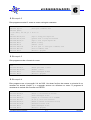
O registo CX contém o tamanho do ficheiro. Se o programa for maior que 64 Kbytes, então o
registo BX irá conter os bytes mais significativos, e CX os menos significativos do tamanho do
ficheiro. Esta informação é muito importante pois é essencial quando se usa o comando Write.
Para além da visualização de todos os registos, o comando R também nos permite editar o
conteúdo de um registo, passando o nome desse registo na linha de comandos como parâmetro
do mesmo:
-R AX
; Mostra o conteúdo do registo AX e permite alterar o seu valor
AX 0000
:
Neste caso a prompt do debug passou a ser (:) o que significa que se digitarmos um valor em
hexadecimal este será o novo conteúdo do registo, se não quisermos alterar o registo, basta
carregar em <ENTER>.
Luís Miguel Charrua Figueiredo
3-2
E.N.I.D.H.
MICROPROCESSADORES
O
D E B U G ,
T A S M
E
T L I N K
3
Comando Dump
O comando Dump (D) permite visualizar grandes áreas de memória. Serve basicamente para
visualizar dados, uma vez que o conteúdo de memória é apresentado em hexadecimal e em ASCII.
Se se quiser ver o código de uma forma mais perceptível, deveremos usar o comando
Unassemble.
Ao introduzir o comando D sem outros parâmetros, ele usa por defeito o DS, e como estamos
normalmente a lidar com programas do tipo *.com, começa com DS:0100h, e por defeito
apresentará um bloco de 80h bytes. Em alternativa poderemos especificar qual o tamanho do
bloco de dados que pretendemos visualizar.
Quando se introduz uma segunda vez o comando, o debug apresentará o bloco de memória
seguinte, se a primeira vez foi o comando sem parâmetros, começa a mostrar a partir da posição
0181h e apresenta o outros 80h bytes, no caso de se ter especificado o tamanho do bloco a
visualizar, este apresentará um novo bloco com o mesmo tamanho que começa a seguir ao
anterior.
-d
; mostra o conteúdo da memória
0CB2:0100
23 81 07 F4 23 82 07 49-24 0F 25 31 20 62 79 74
#...#..I$.%1 byt
0CB2:0110
65 73 20 66 72 65 65 0D-0A 23 46 69 34 00 A1 0C
es free..#Fi4...
0CB2:0120
61 6E 6E 6F 74 20 62 65-20 63 6F 70 69 65 64 20
annot be copied
0CB2:0130
6F 6E 74 6F 20 69 74 73-65 6C 66 0D 0A 19 49 6E
onto itself...In
0CB2:0140
73 75 66 66 69 63 69 65-6E 74 20 64 69 73 6B 20
sufficient disk
0CB2:0150
73 70 61 63 65 0D 0A 13-49 6E 76 61 6C 69 64 20
space...Invalid
0CB2:0160
63 6F 64 65 20 70 61 67-65 0D 0A 0E 49 6E 76 61
code page...Inva
0CB2:0170
6C 69 64 20 64 61 74 65-0D 0A 0E 49 6E 76 61 6C
lid date...Inval
-
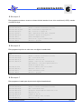
Na caixa de texto de exemplo do comando Dump, podemos ver que está dividido em três áreas: a
primeira com os endereços do primeiro byte de cada linha no formato segmento:offset; a segunda
apresenta-nos o conteúdo da memória em formato hexadecimal; e a terceira o mesmo conteúdo
em formato ASCII, notar que apenas são apresentados os caracteres standard, os restantes são
substituídos por pontos.
O comando Dump está limitado a blocos de 64K bytes, e não pode ultrapassar os limites do
segmento.
O comando Search
O comando search (S) é usado para procurar uma ocorrência de um byte, ou de um conjunto de
bytes. Os dados a procurar podem ser introduzidos em formato hexadecimal ou em formato de
string de texto. Se for em hexadecimal os bytes deverão ser separados por um espaço ou por uma
virgula. Se for em string de texto, a string deve estar contida entre aspas.
Luís Miguel Charrua Figueiredo
3-3
E.N.I.D.H.
MICROPROCESSADORES
O
D E B U G ,
T A S M
E
T L I N K
3
O comando Compare
Este comando (Compare – C) serve para comparar dois blocos de memória, byte a byte. No caso
de haver diferença o byte correspondente de cada bloco é apresentado. Por exemplo para
comparar DS:0100h e DS:0200h em 8 bytes.
-c 0100 l 8 0200
; compara um conjunto de 8 bytes a partir da posição 0100h com os que
; começam em 0200h
0CA3:0100
23
20
0CA3:0200
0CA3:0101
81
69
0CA3:0201
0CA3:0102
07
6E
0CA3:0202
0CA3:0103
F4
20
0CA3:0203
0CA3:0104
23
64
0CA3:0204
0CA3:0105
82
72
0CA3:0205
0CA3:0106
07
69
0CA3:0206
0CA3:0107
49
76
0CA3:0207
-
O comando Unassemble
Para efectuar debugging, um dos comandos mais importantes é o unassemble (U). Este comando
“pega” no código de máquina, e apresenta-o em formato de instruções assembly.
Este comando é semelhante aos anteriores no que diz respeito aos parâmetros possíveis de
introduzir na linha de comandos.
-U
; apresenta a tradução do conteúdo da memória em mnemónicas assembler
6897:0100 E96B01
JMP
026E
6897:0103 43
INC
BX
6897:0104 4C
DEC
SP
6897:0105 4F
DEC
DI
6897:0106 43
INC
BX
6897:0107 4B
DEC
BX
O comando unassemble pode levar a resultados bastante interessantes, por exemplo, se CS:IP for
6897:0100h, olhamos para o programa e vemos que tem a instrução JMP seguido por instruções
que se sabem ser inválidas (ver capítulo com o conjunto de instruções do 8086), assim podemos
dizer que o unassemble apenas intrepreta os códigos hexadecimais e descidifica-os directamente
para instruções assembly sem verificar a sua validade.
Luís Miguel Charrua Figueiredo
3-4
E.N.I.D.H.
MICROPROCESSADORES
O
D E B U G ,
T A S M
E
T L I N K
3
Comandos de introdução de dados
O comando Enter
O comando Enter (E) é usado para colocar bytes de dados na memória. Tem dois modos de
funcionamento: visualização/midificação e substituição. A diferênça está na forma de introdução de
dados, na linha de comandos ou na prompt do comando.
Se dermos apenas o comando E endereço, estamos no primeiro modo, e que o debug nos
mostra o endereço e o conteúdo desse endereço seguido de um ponto. Podemos então introduzir
dados em formato hexadecimal, se não se quiser alterar o valor, basta carreger em <Enter>, se se
introduzir um espaço, esse byte fica inalterado, se se continuar a introduzr valores, estes vão
sendo colocados nos endereços seguintes ao especificado inicialmente na linha de comandos.
Se houver um engano na introdução de dados, podemos usar a tecla < - > para voltar atrás um
byte para sair deste modo basta carregar em <Enter>.
-E 103
; permite a introdução de dados na posição de memória 103h e seguintes
6897:0103
43.41
4C.42
4F.43
6897:0108
2E.46
41.40
53.-
6897:0109
40.47
53.
43.
4B.45
A outra forma de (substituição) é usada para grandes quantidades de dados, ou para strings de
texto, em que se digita o comando seguido do endereço inicial e a string de texto ou conjunto de
bytes a colocar nesses endereços.
-E 0200 'Microprocessadores' 30 "ENIDH"
-D 0200 l 18
0CB2:0200
4D 69 63 72 6F 70 72 6F-63 65 73 73 61 64 6F 72
Microprocessador
0CB2:0210
65 73 30 45 4E 49 44 48
es0ENIDH
-
O comando Fill
Como o nome indica o comando fill (F) serve para preencher grandes quantidades de memória
com os dados que quisermos. Este comando tem a seguinte forma:
-d 0200 l 2f
; apresenta o conteúdo de um bloco de memória com 2fh bytes a partir da
; posição 0200h
0CB2:0200
4D 69 63 72 6F 70 72 6F-63 65 73 73 61 64 6F 72
Microprocessador
0CB2:0210
65 73 30 45 4E 49 44 48-75 6D 65 20 53 65 72 69
es0ENIDHume Seri
0CB2:0220
61 6C 20 4E 75 6D 62 65-72 20 69 73 20 25 31
al Number is %1
-f 0200 l 1f 00
; preenche um bloco de memória de 1fh bytes a partir da posição 0200h com 00h
-d 0200 l 2f
; explicado anteriormente
Luís Miguel Charrua Figueiredo
3-5
E.N.I.D.H.
MICROPROCESSADORES
O
D E B U G ,
T A S M
E
T L I N K
0CB2:0200
00 00 00 00 00 00 00 00-00 00 00 00 00 00 00 00
................
0CB2:0210
00 00 00 00 00 00 00 00-00 00 00 00 00 00 00 69
...............i
0CB2:0220
61 6C 20 4E 75 6D 62 65-72 20 69 73 20 25 31
al Number is %1
-f 021f l 10 'abcd'
3
; preenche um bloco de 10h bytes com a string ‘abcd’
-d 0200 l 2f
0CB2:0200
00 00 00 00 00 00 00 00-00 00 00 00 00 00 00 00
................
0CB2:0210
00 00 00 00 00 00 00 00-00 00 00 00 00 00 00 61
...............a
0CB2:0220
62 63 64 61 62 63 64 61-62 63 64 61 62 63 64
bcdabcdabcdabcd
-
Podemos ver que inicialmente a memória estava com dados, e após o primeiro comando de fill,
parte ficou com o valor 00h, tal como pretendido, da segunda vez, fomos preencher com a string
abcd o restante bloco de memória.
O comando Assemble
O comando assemble (A) é o mais complexo destes comandos de edição. Ele aceita instruções em
assembly e converte-as em código de máquina. No entanto não aceita labels, set equates, use
macros, nem outros tipos de directivas a que estamos normalmente habituados. Qualquer tipo de
instrução de salto deverá ser feita com o endereço absoluto.
TASM
Mov AX,1234
Mov AX,L1234
Mov AX,CS:1234
Movs Byte ptr ...
Movs Word ptr ...
Ret
Ret
DEBUG
Mov AX,1234
Mov AX,[1234]
CS:Mov AX,[1234]
Movesb
Movsw
Ret
Retf
Comments
Place 1234 into AX
Contents of add. 1234 to AX
Move from offset of CS.
Move byte string
Move word string
Near return
Far return
Tabela 10 - Comparação entre modos de introdução do Debug e Tasm.
Na tabela 10, podemos verificar algumas das específicidades e diferênças entre o Tasm e o
Debug.
Exemplo de um pequeno programa
-A 100
6897:0100 mov ax,600
6897:0103 mov cx,0
6897:0106 mov dx,184f
6897:0109 mov bh,07
6897:010B int 10
6897:010D int 20
6897:010F
-
Luís Miguel Charrua Figueiredo
3-6
E.N.I.D.H.
MICROPROCESSADORES
O
D E B U G ,
T A S M
E
T L I N K
3
Ao criar programas com o debug, os esmos devem terminar com INT 20h, que é uma função do
DOS para terminar o programa, se não for colocada, o debug continuará a tentar descodificar e
executar as instruções nas posições seguintes (sejam elas válidas ou não) e poderá “pendurar” o
PC, obrigando a um reboot ou até um power cycle.
Comandos de I/O
O comando Name
O comando name (N) tem apenas um propósito, indicar ao debug qual o nome do ficheiro a ser
escrito ou lido. Ao usar o comando name deveremos colocar o nome e extensão do ficheiro.
O comando Load
Este comando carrega o ficheiro específicado com o comando name, e coloca o seu conteúdo a
começar em IP=0100h, e o registo CX deverá conter o tamanho do ficheiro.
O comando Write
O comando write (W) serve para escrever o ficheiro para o disco, assume que os dados do ficheiro
começam em IP=0100h e usa BX e CX para saber qual a quantidade de bytes a escrever em
disco.
O comando Input
O comando input (I) serve para ler um byte de qualquer porto de I/O do PC. o endereço do porto
pode ser de um ou dois bytes.
-i 3fd
7D
-
O comando Output
O comando output (O) é o inverso do comando input, ou seja, serve para escrever dados para um
porto de I/O do PC.
-o 3fc 1
-
Luís Miguel Charrua Figueiredo
3-7
E.N.I.D.H.
MICROPROCESSADORES
O
D E B U G ,
T A S M
E
T L I N K
3
Comandos de execução
O comando Go
Este comando serve para executar o programa, por defeito assume que o programa começa na
posição CS:IP, no entanto poderemos indicar que queremos iniciar a execução noutro ponto
qualquer do programa. Poderemos usar também até 10 breakpoints através da linha de comando.
O comando Trace
Este comando serve para executar instruções uma de cada vez (passo a passo), ou um conjunto
especificado de instruções, por defeito começa a executar na posição CS:IP e executa um passo.
Outros comandos
Existe ainda o comando Hexaritmethic (H) que é usado para calcular a soma e diferença de dois
números hexadecimais.
Temos ainda o comando help (?) que os dá a lista de comandos disponível e os parâmetros
possíveis.
-?
assemble
A [address]
compare
C range address
dump
D [range]
enter
E address [list]
fill
F range list
go
G [=address] [addresses]
hex
H value1 value2
input
I port
load
L [address] [drive] [firstsector] [number]
move
M range address
name
N [pathname] [arglist]
output
O port byte
proceed
P [=address] [number]
quit
Q
register
R [register]
search
S range list
trace
T [=address] [value]
unassemble
U [range]
write
W [address] [drive] [firstsector] [number]
Luís Miguel Charrua Figueiredo
3-8
E.N.I.D.H.
MICROPROCESSADORES
O
D E B U G ,
allocate expanded memory
XA [#pages]
deallocate expanded memory
XD [handle]
map expanded memory pages
XM [Lpage] [Ppage] [handle]
display expanded memory status
XS
T A S M
E
T L I N K
3
-
O Tasm e Tlink
Como já foi dito, o Tasm é o compilador que “transforma“ os ficheiros *.asm num formato
intermédio (*.obj) e o Tlink faz o trabalho final convertendo-os para ficheiros do tipo COM ou EXE.
No entanto falta mencionar o que são os ficheiros ASM, e de que forma são estruturados. Os
ficheiros ASM são ficheiros de texto, mas cuja extensão nos permite identificar que são ficheiros
com instruções assembly de um determinado programa.
Para se criar um programa em assembly, o ficheiro fonte (ASM) deverá estar estruturado da
seguinte forma:
; use ; para fazer comentários em programas assembly
.INCLUDE macro.ext
;directiva para incluir um ficheiro de macros
.MODEL SMALL
;modelo de memória
.STACK
;espaço de memória para instruções do programa na stack
.CODE
;as linhas seguintes são instruções do programa
mov ah,01h
;move o valor 01h para o registo ah
mov cx,07h
;move o valor 07h para o registo cx
int 10h
;interrupção 10h
mov ah,4ch
;move o valor 4ch para o registo ah
int 21h
;interrupção 21h
END
;finaliza o código do programa
Para compilar o programa:
C:\>tasm exam1.asm
Turbo Assembler Version 2.0 Copyright (c) 1988, 1990 Borland International
Assembling file: exam1.asm
Error messages: None
Warning messages: None
Passes: 1
Remaining memory: 471k
Se não houver problemas
Luís Miguel Charrua Figueiredo
3-9
E.N.I.D.H.
MICROPROCESSADORES
O
D E B U G ,
T A S M
E
T L I N K
3
C:\>tlink exam1.obj
Turbo Link Version 3.0 Copyright (c) 1987, 1990 Borland International
C:\>
O resultado é um ficheiro exam1.exe que pode agora ser executado.
Para a criação e edição dos ficheiros ASM, aconselho um editor tal como o EDIT Plus 2 ao qual se
pode acrescentar um ficheiro relativo ao assembly do 8086, permitindo-nos que ao editar tenhamos
o código realçado com cores de acordo com o tipo de elementos (sintaxe highligth) por forma a ser
mais fácil analisar o código. No entanto poderemos utilizar qualquer tipo de editor que nos permita
gravar ficheiros em formato ASCII com a extensão ASM.
A utilização do Tasm e Tlink em vez do Debug, para além da facilidade de edição e análise do
código, permite-nos ainda fazer uso de macros e procedimentos, que não é possível em Debug.
Uma das formas mais práticas de criar programas usando linguagem assembly, será gerar o
código fonte com um editor, fazer a sua compilação com o Tasm e Tlink, e em caso de problemas
usar o debug para a execução passo a passo ou com o auxilio de breakpoints até se encontrar o
problema e se efectuar a correcção novamente com o editor de texto.
Macros e Procedimentos
Uma das grandes vantagens de se trabalhar com ficheiros de código que são depois compilados, é
que poderemos criar e usar macros e procedimentos. Ao programar em linguagens de alto nível
(C, Basic, etc.) quando existe um conjunto de operações repetitivas ao longo do programa,
normalmente são agrupadas em funções ou sub-rotinas, em assembler chamam-se macros e
procedimentos (procedures). A diferênça entre macros e procedimentos, é que nos procedimentos
não passamos parametros ao chamarmos o procedimento, enquanto uma macro pode receber
parametros ao ser chamada.
Procedimentos
Há dois tipos de procedimentos, os intrasegmento, que se situa no mesmo segmento de código da
instrução que o chama, e os intersegmento, que estão num segmento de memória diferente da
instrução que o chama.
Quando os procedimentos intrasegmento são usados, o valor de IP é colocado na Stack, quando
são intersegmentos, é o valor CS:IP que é colocado na Stack.
A instrução que chama um procedimento é como segue:
CALL NomedoProcedimento
As partes que compõem um procedimento são as seguintes:
Luís Miguel Charrua Figueiredo
3 - 10
E.N.I.D.H.
MICROPROCESSADORES
O
•
•
•
•
D E B U G ,
T A S M
E
T L I N K
3
Declaração do procedimento
Código do procedimento
Diretiva de retorno
Término do procedimento
Por exemplo, se quisermos uma rotina que soma dois bytes armazenados em AH e AL, e o
resultado da soma em BX:
Soma Proc Near
Mov BX, 0
; Declaração do Procedimento
; Conteúdo do Procedimento...
Mov BL, AH
Mov AH, 00
Add BX, AX
Ret
Soma EndP
; instrução de retorno
; Fim do Procedimento
Na declaração, a primeira palavra, Soma, corresponde ao nome do procedimento. Proc declara-o e
a palavra Near indica que o procedimento é do tipo intrasegmento, ou seja, no mesmo segmento.
A instrução Ret carrega IP com o endereço armazenado na Stack para retornar ao programa que
chamou. Finalmente, Soma EndP indica o fim do procedimento. Para declarar um procedimento
inter segmento, basta substituir a directiva Near para FAR. A chamada deste procedimento é feito
de modo idêntico.
Macros
As macros como já foi dito permitem a passagem de parametros no momento da sua chamada, e
são chamadas com se de uma instrução assembly se trata-se, isto permite uma maior flexibilidade,
sendo que as macros podem ser utilizadas por mais do que um só programa,
Normalmente são guardadas em ficheiros separados e incluidos no programa principal através da
directiva include no inicio do programa.
As partes que compõem uma macro são as seguintes:
•
•
•
Declaração da macro
Código da macro
Diretiva de término da macro
A declaração da macro é feita como se segue:
NomeMacro MACRO [parâmetro1, parâmetro2...]
Do mesmo modo que temos a funcionalidade dos parâmetros, é possível também a criação de
uma macro que não os possua. A diretiva de término da macro é: ENDM
Luís Miguel Charrua Figueiredo
3 - 11
E.N.I.D.H.
MICROPROCESSADORES
O
D E B U G ,
T A S M
E
T L I N K
3
Um exemplo de uma macro para colocar o cursor numa determinada posição do
ecran:
Pos MACRO Linha, Coluna
PUSH AX
PUSH BX
PUSH DX
MOV AH, 02H
MOV DH, Linha
MOV DL, Coluna
MOV BH, 0
INT 10H
POP DX
POP BX
POP AX
ENDM
Para usar uma macro basta chamá-la pelo seu nome, tal como se fosse qualquer instrução na
linguagem assembly:
Pos 8, 6
Luís Miguel Charrua Figueiredo
3 - 12
E.N.I.D.H.
MICROPROCESSADORES
C O N J U N T O
D E
Conjunto de
Instruções do 8086
I N S T R U Ç Õ E S
D O
8 0 8 6
4
Sums two binary operands placing the result in the
destination. If CF is set, a 1 is added to the destination.
ADD - Arithmetic Addition
Usage: ADD
Instruções detalhadas
dest,src
Modifies flags: AF CF OF PF SF ZF
Adds "src" to "dest" and replacing the original contents of
"dest". Both operands are binary.
AAA - Ascii Adjust for Addition
Usage: AAA
AND - Logical And
Modifies flags: AF CF (OF,PF,SF,ZF undefined)
Usage: AND
Changes contents of AL to valid unpacked decimal. The
Modifies flags: CF OF PF SF ZF (AF undefined)
high order nibble is zeroed.
Performs a logical AND of the two operands replacing the
dest,src
destination with the result.
AAD - Ascii Adjust for Division
Usage: AAD
CALL - Procedure Call
Modifies flags: SF ZF PF (AF,CF,OF undefined)
Usage: CALL
Used
before dividing
unpacked
decimal
destination
Modifies flags: None
numbers.
Multiplies AH by 10 and the adds result into AL. Sets AH
Pushes Instruction Pointer (and Code Segment for far
to zero.
calls) onto stack and loads Instruction Pointer with the
This instruction is also known to have an
address of proc-name. Code continues with execution at
undocumented behavior.
CS:IP.
AL := 10*AH+AL
AH := 0
CBW - Convert Byte to Word
AAM - Ascii Adjust for Multiplication
Usage: CBW
Usage: AAM
Modifies flags: None
Modifies flags: PF SF ZF (AF,CF,OF undefined)
Converts byte in AL to word Value in AX by extending
sign of AL throughout register AH.
AH := AL / 10
AL := AL mod 10
Used after multiplication of two unpacked decimal
CLC - Clear Carry
numbers, this instruction adjusts an unpacked decimal
Usage: CLC
number.
Modifies flags: CF
The high order nibble of each byte must be
Clears the Carry Flag.
zeroed before using this instruction. This instruction is
also known to have an undocumented behavior.
CLD - Clear Direction Flag
AAS - Ascii Adjust for Subtraction
Usage: CLD
Usage: AAS
Modifies flags: DF
Modifies flags: AF CF (OF,PF,SF,ZF undefined)
Clears the Direction Flag causing string instructions to
Corrects
result
of
a
previous
unpacked
increment the SI and DI index registers.
decimal
subtraction in AL. High order nibble is zeroed.
CLI - Clear Interrupt Flag (disable)
ADC - Add With Carry
Usage: CLI
Usage: ADC
Modifies flags: IF
dest,src
Modifies flags: AF CF OF SF PF ZF
Luís Miguel Charrua Figueiredo
4-1
E.N.I.D.H.
MICROPROCESSADORES
C O N J U N T O
D E
I N S T R U Ç Õ E S
D O
8 0 8 6
4
Disables the maskable hardware interrupts by clearing the
Modifies flags: AF CF PF SF ZF (OF undefined)
Interrupt flag. NMI's and software interrupts are not
Corrects result (in AL) of a previous BCD subtraction
inhibited.
operation. Contents of AL are changed to a pair of packed
decimal digits.
CMC - Complement Carry Flag
Usage: CMC
DEC - Decrement
Modifies flags: CF
Usage: DEC
Toggles (inverts) the Carry Flag
Modifies flags: AF OF PF SF ZF
dest
Unsigned binary subtraction of one from the destination.
CMP - Compare
Usage: CMP
DIV - Divide
dest,src
Modifies flags: AF CF OF PF SF ZF
Usage: DIV
Subtracts source from destination and updates the flags
Modifies flags: (AF,CF,OF,PF,SF,ZF undefined)
but does not save result.
Unsigned binary division of accumulator by source. If the
Flags can subsequently be
src
source divisor is a byte value then AX is divided by "src"
checked for conditions.
and the quotient is placed in AL and the remainder in AH.
CMPS - Compare String (Byte, Word or Doubleword)
If source operand is a word value, then DX:AX is divided
Usage: CMPS
by "src" and the quotient is stored in AX and the
dest,src
remainder in DX.
CMPSB
CMPSW
Modifies flags: AF CF OF PF SF ZF
ESC - Escape
Subtracts destination value from source without saving
Usage: ESC
results. Updates flags based on the subtraction and the
Modifies flags: None
index registers (E)SI and (E)DI are incremented or
Provides access to the data bus for other resident
decremented depending on the state of the Direction
processors. The CPU treats it as a NOP but places
Flag. CMPSB inc/decrements the index
memory operand on bus.
1,
CMPSW
inc/decrements
by
2,
registers by
while
immed,src
CMPSD
increments or decrements by 4. The REP prefixes can be
HLT - Halt CPU
used to process entire data items.
Usage: HLT
Modifies flags: None
CWD - Convert Word to Doubleword
Halts CPU until RESET line is activated, NMI or maskable
Usage: CWD
interrupt received.
Modifies flags: None
retains the current CS:IP for later restart.
The CPU becomes dormant but
Extends sign of word in register AX throughout register
IDIV - Signed Integer Division
DX forming a doubleword quantity in DX:AX.
Usage: IDIV src
DAA - Decimal Adjust for Addition
Modifies flags: (AF,CF,OF,PF,SF,ZF undefined)
Usage: DAA
Signed binary division of accumulator by source.
Modifies flags: AF CF PF SF ZF (OF undefined)
source is a byte value, AX is divided by "src" and the
Corrects result (in AL) of a previous BCD addition
quotient is stored in AL and the remainder in AH.
operation. Contents of AL are changed to a pair of packed
source is a word value, DX:AX is divided by "src", and the
decimal digits.
quotient is stored in AL and the remainder in DX.
IMUL - Signed Multiply
DAS - Decimal Adjust for Subtraction
Usage: IMUL
Usage: DAS
Modifies flags: CF OF (AF,PF,SF,ZF undefined)
Luís Miguel Charrua Figueiredo
4-2
src
E.N.I.D.H.
If
If
MICROPROCESSADORES
C O N J U N T O
D E
I N S T R U Ç Õ E S
D O
8 0 8 6
4
Signed multiplication of accumulator by "src" with result
return to the instruction that cause the exception because
placed in the accumulator. If the source operand is a byte
the CS:IP placed on the stack during the interrupt is the
value, it is multiplied by AL and the result stored in AX. If
address of the offending instruction.
the source operand is a word value it is multiplied by AX
Jxx - Jump Instructions Table
and the result is stored in DX:AX. Other variations of this
Mnemonic
Meaning
JA
Jump if Above
JAE
Jump if Above or Equal
JB
Jump if Below
JBE
Jump if Below or Equal
JC
Jump if Carry
JCXZ
Jump if CX Zero
JE
Jump if Equal
JG
Jump if Greater (signed)
JGE
Jump if Greatur or Equal (signed)
JL
Jump if Less (signed)
JLE
Jump if Less or Equal (signed)
JMP
Unconditional Jump
JNA
Jump if Not Above
JNAE
Jump if Not Above or Equal
JNB
Jump if Not Below
JNBE
Jump if Not Below or Equal
JNC
Jump if Not Carry
JNE
Jump if Not Equal
JNG
Jmp if Not Greater (signed)
JNGE
Jump if Not Greater or Equal (signed)
JNL
Jump if Not Less (signed)
JNLE
Jump if Not Less or Equal (signed)
JNO
Jump if Not Overflow (signed)
JNP
Jump if No Parity
JNS
Jump if Not Signed (signed)
JNZ
Jump if Not Zero
JO
Jump if Overflow (signed)
JP
Jump if Parity
JPE
Jump if Parity Even
JPO
Jump if Parity Odd
JS
Jump if Signed (signed)
JZ
Jump if Zero
instruction allow specification of source and destination
registers as well as a third immediate factor.
IN - Input Byte or Word From Port
Usage: IN
accum,port
Modifies flags: None
A byte, word or dword is read from "port" and placed in
AL, AX or EAX respectively. If the port number is in the
range of 0-255 it can be specified as an immediate,
otherwise the port number must be specified in DX. Valid
port ranges on the PC are 0-1024, though values through
65535 may be specified and recognized by third party
vendors and PS/2's.
INC - Increment
Usage: INC
dest
Modifies flags: AF OF PF SF ZF
Adds one to destination unsigned binary operand.
INT - Interrupt
Usage: INT
num
Modifies flags: TF IF
Initiates a software interrupt by pushing the flags, clearing
Jump Condition
CF=0 and ZF=0
CF=0
CF=1
CF=1 or ZF=1
CF=1
CX=0
ZF=1
ZF=0 and SF=OF
SF=OF
SF != OF
ZF=1 or SF != OF
unconditional
CF=1 or ZF=1
CF=1
CF=0
CF=0 and ZF=0
CF=0
ZF=0
ZF=1 or SF != OF
SF != OF
SF=OF
ZF=0 and SF=OF
OF=0
PF=0
SF=0
ZF=0
OF=1
PF=1
PF=1
PF=0
SF=1
ZF=1
Tabela 11 - Lista e condições das intruções de salto.
the Trap and Interrupt Flags, pushing CS followed by IP
and loading CS:IP with the value found in the interrupt
vector table.
JCXZ - Jump if Register (E)CX is Zero
Execution then begins at the location
Usage: JCXZ
addressed by the new CS:IP
label
Modifies flags: None
Causes execution to branch to "label" if register CX is
INTO - Interrupt on Overflow
zero. Uses unsigned comparision.
Usage: INTO
Modifies flags: IF TF
JMP - Unconditional Jump
If the Overflow Flag is set this instruction generates an
Usage: JMP
INT 4 which causes the code addressed by 0000:0010 to
target
Modifies flags: None
be executed.
Unconditionally transfers control to "label".
Jumps by
default are within -32768 to 32767 bytes from the
IRET - Interrupt Return
instruction following the jump. NEAR and SHORT jumps
Usage: IRET
cause the IP to be updated while FAR jumps cause CS
Modifies flags: AF CF DF IF PF SF TF ZF
and IP to be updated.
Returns control to point of interruption by popping IP, CS
and then the Flags from the stack and continues
LAHF - Load Register AH From Flags
execution at this location. CPU exception interrupts will
Luís Miguel Charrua Figueiredo
4-3
E.N.I.D.H.
MICROPROCESSADORES
C O N J U N T O
D E
I N S T R U Ç Õ E S
Usage: LODS
Usage: LAHF
D O
8 0 8 6
4
src
LODSB
Modifies flags: None
LODSW
Copies bits 0-7 of the flags register into AH. This includes
Modifies flags: None
flags AF, CF, PF, SF and ZF other bits are undefined.
Transfers string element addressed by DS:SI (even if an
AH := SF ZF xx AF xx PF xx CF
operand is supplied) to the accumulator.
SI is
LDS - Load Pointer Using DS
incremented based on the size of the operand or based
Usage: LDS
on the instruction used. If the Direction Flag is set SI is
dest,src
Modifies flags: None
decremented, if the Direction Flag is clear SI is
Loads 32-bit pointer from memory source to destination
incremented. Use with REP prefixes.
register and DS. The offset is placed in the destination
register and the segment is placed in DS. To use this
LOOP - Decrement CX and Loop if CX Not Zero
instruction the word at the lower memory address must
Usage: LOOP
contain the offset and the word at the higher address
Modifies flags: None
must contain the segment. This simplifies the loading of
Decrements CX by 1 and transfers control to "label" if CX
far pointers from the stack and the interrupt vector table.
is not Zero. The "label" operand must be within -128 or
label
127 bytes of the instruction following the loop instruction.
LEA - Load Effective Address
Usage: LEA
LOOPE/LOOPZ - Loop While Equal / Loop While Zero
dest,src
Usage: LOOPE label
Modifies flags: None
LOOPZ label
Transfers offset address of "src" to the destination
Modifies flags: None
register.
Decrements CX by 1 (without modifying the flags) and
LES - Load Pointer Using ES
transfers control to "label" if CX != 0 and the Zero Flag is
Usage: LES
set. The "label" operand must be within -128 or 127 bytes
dest,src
of the instruction following the loop instruction.
Modifies flags: None
Loads 32-bit pointer from memory source to destination
register and ES. The offset is placed in the destination
LOOPNZ/LOOPNE - Loop While Not Zero / Loop While
register and the segment is placed in ES. To use this
Not Equal
instruction the word at the lower memory address must
Usage: LOOPNZ label
LOOPNE label
contain the offset and the word at the higher address
must contain the segment. This simplifies the loading of
Modifies flags: None
far pointers from the stack and the interrupt vector table.
Decrements CX by 1 (without modifying the flags) and
transfers control to "label" if CX != 0 and the Zero Flag is
LOCK - Lock Bus
clear. The "label" operand must be within -128 or 127
Usage: LOCK
bytes of the instruction following the loop instruction.
Modifies flags: None
This instruction is a prefix that causes the CPU assert bus
MOV - Move Byte or Word
lock signal during the execution of the next instruction.
Usage: MOV
Used to avoid two processors from updating the same
Modifies flags: None
data location.
dest,src
The 286 always asserts lock during an
Copies byte or word from the source operand to the
XCHG with memory operands. This should only be used
destination operand. If the destination is SS interrupts are
to lock the bus prior to XCHG, MOV, IN and OUT
disabled except on early buggy 808x CPUs. Some CPUs
instructions.
disable interrupts if the destination is any of the segment
registers
LODS - Load String (Byte, Word or Double)
Luís Miguel Charrua Figueiredo
4-4
E.N.I.D.H.
MICROPROCESSADORES
C O N J U N T O
D E
I N S T R U Ç Õ E S
D O
8 0 8 6
4
MOVS - Move String (Byte or Word)
Modifies flags: CF OF PF SF ZF (AF undefined)
Usage: MOVS
Logical inclusive OR of the two operands returning the
dest,src
MOVSB
result in the destination. Any bit set in either operand will
MOVSW
be set in the destination.
Modifies flags: None
Copies data from addressed by DS:SI (even if operands
OUT - Output Data to Port
are given) to the location ES:DI destination and updates
Usage: OUT
SI and DI based on the size of the operand or instruction
Modifies flags: None
used. SI and DI are incremented when the Direction Flag
Transfers byte in AL,word in AX or dword in EAX to the
is cleared and decremented when the Direction Flag is
specified hardware port address. If the port number is in
Set. Use with REP prefixes.
the range of 0-255 it can be specified as an immediate. If
port,accum
greater than 255 then the port number must be specified
MUL - Unsigned Multiply
in DX. Since the PC only decodes 10 bits of the port
Usage: MUL
address, values over 1023 can only be decoded by third
src
Modifies flags: CF OF (AF,PF,SF,ZF undefined)
party vendor equipment and also map to the port range 0-
Unsigned multiply of the accumulator by the source. If
1023.
"src" is a byte value, then AL is used as the other
multiplicand and the result is placed in AX. If "src" is a
POP - Pop Word off Stack
word value, then AX is multiplied by "src" and DX:AX
Usage: POP
receives the result. If "src" is a double word value, then
Modifies flags: None
EAX is multiplied by "src" and EDX:EAX receives the
Transfers word at the current stack top (SS:SP) to the
result.
destination then increments SP by two to point to the new
The 386+ uses an early out algorithm which
dest
stack top. CS is not a valid destination.
makes multiplying any size value in EAX as fast as in the
8 or 16 bit registers.
POPF/POPFD - Pop Flags off Stack
NEG - Two's Complement Negation
Usage: POPF
Usage: NEG
Modifies flags: all flags
dest
Modifies flags: AF CF OF PF SF ZF
Pops word/doubleword from stack into the Flags Register
Subtracts the destination from 0 and saves the 2s
and then increments SP by 2 (for POPF) or 4 (for
complement of "dest" back into "dest".
POPFD).
NOP - No Operation (90h)
PUSH - Push Word onto Stack
Usage: NOP
Usage: PUSH
Modifies flags: None
Modifies flags: None
This is a do nothing instruction. It results in occupation of
Decrements SP by the size of the operand (two or four,
both space and time and is most useful for patching code
byte values are sign extended) and transfers one word
segments. (This is the original XCHG AL,AL instruction)
from source to the stack top (SS:SP).
src
NOT - One's Compliment Negation (Logical NOT)
PUSHF/PUSHFD - Push Flags onto Stack
Usage: NOT
Usage: PUSHF
dest
Modifies flags: None
Modifies flags: None
Inverts the bits of the "dest" operand forming the 1s
Transfers the Flags Register onto the stack.
complement.
saves a 16 bit value while PUSHFD saves a 32 bit value.
OR - Inclusive Logical OR
RCL - Rotate Through Carry Left
Usage: OR
Usage: RCL
dest,src
Luís Miguel Charrua Figueiredo
4-5
PUSHF
dest,count
E.N.I.D.H.
4
MICROPROCESSADORES
C O N J U N T O
D E
I N S T R U Ç Õ E S
D O
8 0 8 6
other than the 386 may result in errors if an interrupt
Modifies flags: CF OF
occurs before CX=0.
C
7
0
REPNE/REPNZ - Repeat Not Equal / Repeat Not Zero
Usage: REPNE
REPNZ
Rotates the bits in the destination to the left "count" times
Modifies flags: None
with all data pushed out the left side re-entering on the
Repeats execution of string instructions while CX != 0 and
right. The Carry Flag holds the last bit rotated out.
the Zero Flag is clear.
CX is decremented and the Zero
Flag tested after each string operation. The combination
RCR - Rotate Through Carry Right
of a repeat prefix and a segment override on processors
Usage: RCR
other than the 386 may result in errors if an interrupt
dest,count
Modifies flags: CF OF
occurs before CX=0.
7
0
C
RET/RETF - Return From Procedure
Usage: RET
Rotates the bits in the destination to the right "count"
nBytes
RETF
nBytes
RETN
nBytes
Modifies flags: None
times with all data pushed out the right side re-entering on
Transfers control from a procedure back to the instruction
the left. The Carry Flag holds the last bit rotated out.
REP - Repeat String Operation
address saved on the stack.
"n bytes" is an optional
number of bytes to release.
Far returns pop the IP
followed by the CS, while near returns pop only the IP
Usage: REP
register.
Modifies flags: None
Repeats execution of string instructions while CX != 0.
ROL - Rotate Left
After each string operation, CX is decremented and the
Usage: ROL
Zero Flag is tested. The combination of a repeat prefix
dest,count
Modifies flags: CF OF
and a segment override on CPU's before the 386 may
result in errors if an interrupt occurs before CX=0. The
C
following code shows code that is susceptible to this and
7
0
how to avoid it:
again: rep movs byte ptr ES:[DI],ES:[SI]
; vulnerable
instr.
Rotates the bits in the destination to the left "count" times
jcxz next
; continue if REP successful
with all data pushed out the left side re-entering on the
loop again
; interrupt goofed count
right. The Carry Flag will contain the value of the last bit
next:
rotated out.
REPE/REPZ - Repeat Equal / Repeat Zero
ROR - Rotate Right
Usage: REPE
Usage: ROR
REPZ
dest,count
Modifies flags: CF OF
Modifies flags: None
Repeats execution of string instructions while CX != 0 and
7
the Zero Flag is set. CX is decremented and the Zero
0
C
Flag tested after each string operation. The combination
of a repeat prefix and a segment override on processors
Luís Miguel Charrua Figueiredo
4-6
E.N.I.D.H.
4
MICROPROCESSADORES
C O N J U N T O
D E
I N S T R U Ç Õ E S
D O
8 0 8 6
Rotates the bits in the destination to the right "count"
Compares value at ES:DI (even if operand is specified)
times with all data pushed out the right side re-entering on
from the accumulator and sets the flags similar to a
the left. The Carry Flag will contain the value of the last
subtraction. DI is incremented/decremented based on the
bit rotated out.
instruction format (or operand size) and the state of the
Direction Flag. Use with REP prefixes.
SAHF - Store AH Register into FLAGS
SHL - Shift Logical Left
Usage: SAHF
See: SAL
Modifies flags: AF CF PF SF ZF
Transfers bits 0-7 of AH into the Flags Register. This
SHR - Shift Logical Right
includes AF, CF, PF, SF and ZF.
Usage: SHR
Usage: SAL
SHL
dest,count
Modifies flags: CF OF PF SF ZF (AF undefined)
SAL/SHL - Shift Arithmetic Left / Shift Logical Left
dest,count
0
dest,count
7
0
C
Modifies flags: CF OF PF SF ZF (AF undefined)
C
7
0
Shifts the destination right by "count" bits with zeroes
0
shifted in on the left. The Carry Flag contains the last bit
shifted out.
Shifts the destination left by "count" bits with zeroes
shifted in on right. The Carry Flag contains the last bit
STC - Set Carry
shifted out.
Usage: STC
Modifies flags: CF
Sets the Carry Flag to 1.
SAR - Shift Arithmetic Right
Usage: SAR
dest,count
STD - Set Direction Flag
Modifies flags: CF OF PF SF ZF (AF undefined)
Usage: STD
7
0
Modifies flags: DF
C
Sets the Direction Flag to 1 causing string instructions to
auto-decrement SI and DI instead of auto-increment.
Shifts the destination right by "count" bits with the current
STI - Set Interrupt Flag (Enable Interrupts)
sign bit replicated in the leftmost bit.
Usage: STI
The Carry Flag
contains the last bit shifted out.
Modifies flags: IF
Sets the Interrupt Flag to 1, which enables recognition of
SBB - Subtract with Borrow/Carry
all hardware interrupts. If an interrupt is generated by a
Usage: SBB
hardware device, an End of Interrupt (EOI) must also be
dest,src
Modifies flags: AF CF OF PF SF ZF
issued to enable other hardware interrupts of the same or
Subtracts the source from the destination, and subtracts 1
lower priority.
extra if the Carry Flag is set.
Results are returned in
"dest".
STOS - Store String (Byte, Word or Doubleword)
Usage: STOS
dest
SCAS - Scan String (Byte, Word or Doubleword)
STOSB
Usage: SCAS
STOSW
string
SCASB
STOSD
SCASW
Modifies flags: None
Modifies flags: AF CF OF PF SF ZF
Luís Miguel Charrua Figueiredo
4-7
E.N.I.D.H.
MICROPROCESSADORES
C O N J U N T O
D E
I N S T R U Ç Õ E S
D O
8 0 8 6
4
Stores value in accumulator to location at ES:(E)DI (even
if operand is given). (E)DI is incremented/decremented
based on the size of the operand (or instruction format)
and the state of
the Direction Flag.
Use with REP
prefixes.
SUB - Subtract
Usage: SUB
dest,src
Modifies flags: AF CF OF PF SF ZF
The source is subtracted from the destination and the
result is stored in the destination.
TEST - Test For Bit Pattern
Usage: TEST
dest,src
Modifies flags: CF OF PF SF ZF (AF undefined)
Performs a logical AND of the two operands updating the
flags register without saving the result.
WAIT/FWAIT - Event Wait
Usage: WAIT
FWAIT
Modifies flags: None
CPU enters wait state until the coprocessor signals it has
finished its operation. This instruction is used to prevent
the CPU from accessing memory that may be temporarily
in use by the coprocessor. WAIT and FWAIT are identical.
XCHG - Exchange
Usage: XCHG
dest,src
Modifies flags: None
Exchanges contents of source and destination.
XLAT/XLATB - Translate
Usage: XLAT
translation-table
XLATB (masm 5.x)
Modifies flags: None
Replaces the byte in AL with byte from a user table
addressed by BX. The original value of AL is the index
into the translate table. The best way to discripe this is
MOV AL,[BX+AL]
XOR - Exclusive OR
Usage: XOR
dest,src
Modifies flags: CF OF PF SF ZF (AF undefined)
Performs a bitwise exclusive OR of the operands and
returns the result in the destination.
Luís Miguel Charrua Figueiredo
4-8
E.N.I.D.H.
MICROPROCESSADORES
I N T E R R U P Ç Õ E S
Interrupções
Iremos agora apresentar alguns dos principais interrupts da BIOS.
INT 10 - VIDEO - SET VIDEO MODE
AH = 00h
AL = desired video mode (see #00010)
Return: AL = video mode flag (Phoenix, AMI BIOS)
20h mode > 7
30h modes 0-5 and 7
3Fh mode 6
AL = CRT controller mode byte (Phoenix 386 BIOS v1.10)
Desc:
specify the display mode for the currently active display adapter
InstallCheck: for Ahead adapters, the signature "AHEAD" at C000h:0025h for
Paradise adapters, the signature "VGA=" at C000h:007Dh for Oak Tech OTI037/057/067/077 chipsets, the signature "OAK VGA" at C000h:0008h for ATI
adapters, the signature "761295520" at C000h:0031h; the byte at C000h:0043h
indicates the chipset revision:
31h for 18800
32h for 18800-1
33h for 18800-2
34h for 18800-4
35h for 18800-5
62h for 68800AX (Mach32) (see also #00732)
the two bytes at C000h:0040h indicate the adapter type
"22" EGA Wonder
"31" VGA Wonder
"32" EGA Wonder800+
the byte at C000h:0042h contains feature flags
bit 1: mouse port present
bit 4: programmable video clock
the byte at C000h:0044h contains additional feature flags if chipset byte > 30h
(see #00009) for Genoa video adapters, the signature 77h XXh 99h 66h at
C000h:NNNNh, where NNNNh is stored at C000h:0037h and XXh is
00h for Genoa 6200/6300
11h for Genoa 6400/6600
22h for Genoa 6100
33h for Genoa 5100/5200
55h for Genoa 5300/5400
for SuperEGA BIOS v2.41+, C000h:0057h contains the product level for Genoa
SuperEGA BIOS v3.0+, C000h:0070h contains the signature "EXTMODE",
indicating support for extended modes
IBM standard modes do not clear the screen if the high bit of AL is set
Notes:
(EGA or higher only) the Tseng ET4000 chipset is used by the Orchid Prodesigner
II, Diamond SpeedSTAR VGA, Groundhog Graphics Shadow VGA, Boca Super X
VGA, Everex EV-673, etc. intercepted by GRAFTABL from Novell DOS 7 and
Caldera OpenDOS 7.01.
SeeAlso:
AX=0070h,AX=007Eh,AX=10E0h,AX=10F0h,AH=40h,AX=6F05h,AH=FFh"GO32"
SeeAlso: INT 33/AX=0028h,INT 5F/AH=00h,INT 62/AX=0001h,MEM 0040h:0049h
installation check;Tseng ET4000|installation check;Ahead video cards
Index:
installation check;Oak Technologies|installation check;ATI video cards
Index:
installation check;Paradise video|installation check;Genoa video cards
Index:
Bitfields for ATI additional feature flags:
Bit(s)
Description (Table 00009)
0
70 Hz non-interlaced display
1
Korean (double-byte) characters
2
45 MHz memory clock rather than 40 MHz
3
zero wait states
4
paged ROMs
6
no 8514/A monitor support
7
HiColor DAC
(Table 00010)
Values for video mode:
Luís Miguel Charrua Figueiredo
5-1
5
text/ text pixel
pixel
colors disply scrn system
grph resol
box resolution
pages addr
00h = T 40x25
8x8 320x200
16gray
8
B800
CGA,PCjr,Tandy
= T 40x25
8x14 320x350
16gray
8 B800 EGA
= T 40x25
8x16 320x400
16
8 B800 MCGA
= T 40x25
9x16 360x400
16
8 B800 VGA
01h = T 40x25
8x8 320x200
16
8
B800
CGA,PCjr,Tandy
= T 40x25
8x14 320x350
16
8 B800 EGA
= T 40x25
8x16 320x400
16
8 B800 MCGA
= T 40x25
9x16 360x400
16
8 B800 VGA
02h = T 80x25
8x8 640x200
16gray
4
B800
CGA,PCjr,Tandy
= T 80x25
8x14 640x350
16gray
8 B800 EGA
= T 80x25
8x16 640x400
16
8 B800 MCGA
= T 80x25
9x16 720x400
16
8 B800 VGA
03h = T 80x25
8x8 640x200
16
4
B800
CGA,PCjr,Tandy
= T 80x25
8x14 640x350
16/64
8 B800 EGA
= T 80x25
8x16 640x400
16
8 B800 MCGA
= T 80x25
9x16 720x400
16
8 B800 VGA
= T 80x43
8x8 640x350
16
4 B800 EGA,VGA
[17]
= T 80x50
8x8 640x400
16
4 B800 VGA [17]
04h = G 40x25
8x8 320x200
4
.
B800
CGA,PCjr,EGA,MCGA,VGA
05h = G 40x25
8x8 320x200
4gray
.
B800
CGA,PCjr,EGA
= G 40x25
8x8 320x200
4
.
B800
MCGA,VGA
06h = G 80x25
8x8 640x200
2
.
B800
CGA,PCjr,EGA,MCGA,VGA
= G 80x25
.
.
mono
.
B000
HERCULES.COM on HGC [14]
07h = T 80x25
9x14 720x350
mono
var
B000
MDA,Hercules,EGA
= T 80x25
9x16 720x400
mono
. B000 VGA
08h = T 132x25
8x8 1056x200
16
.
B800 ATI
EGA/VGA Wonder [2]
= T 132x25
8x8 1056x200
mono
.
B000 ATI
EGA/VGA Wonder [2]
= G 20x25
8x8 160x200
16
.
. PCjr,
Tandy 1000
= G 80x25
8x16 640x400
color
.
. Tandy
2000
= G 90x43
8x8 720x348
mono
. B000 Hercules +
MSHERC.COM
= G 90x45
8x8 720x360
mono
. B000 Hercules +
HERKULES [11]
= G 90x29
8x12 720x348
mono
.
.
Hercules + HERCBIOS [15]
09h = G 40x25
8x8 320x200
16
.
. PCjr,
Tandy 1000
= G 80x25
8x16 640x400
mono
.
. Tandy
2000
= G 90x43
8x8 720x348
mono
.
.
Hercules + HERCBIOS [15]
0Ah = G 80x25
8x8 640x200
4
.
. PCjr,
Tandy 1000
0Bh =
reserved
(EGA
BIOS
internal use)
= G 80x25
8x8 640x200
16
.
. Tandy
1000 SL/TL [13]
0Ch =
reserved
(EGA
BIOS
internal use)
0Dh = G 40x25
8x8 320x200
16
8 A000 EGA,VGA
0Eh = G 80x25
8x8 640x200
16
4 A000 EGA,VGA
0Fh = G 80x25
8x14 640x350
mono
2 A000 EGA,VGA
10h = G 80x25
8x14 640x350
4
2 A000 64k EGA
E.N.I.D.H.
MICROPROCESSADORES
I N T E R R U P Ç Õ E S
= G . . 640x350
16
. A000 256k EGA,VGA
11h = G 80x30
8x16 640x480
mono
.
A000
VGA,MCGA,ATI EGA,ATI VIP
12h = G 80x30
8x16 640x480
16/256K . A000 VGA,ATI VIP
= G 80x30
8x16 640x480
16/64
. A000 ATI EGA
Wonder
= G . . 640x480
16
.
. UltraVision+256K
EGA
13h = G 40x25
8x8 320x200
256/256K
.
A000
VGA,MCGA,ATI VIP
14h = T 132x25
Nx16
.
16
. B800 XGA, IBM
Enhanced VGA [3]
= T 132x25
8x16 1056x400
16/256K . .
Cirrus CLGD5420/5422/5426
= G 80x25
8x8 640x200
.
.
. Lava
Chrome II EGA
= G . . 640x400
16
.
. Tecmar VGA/AD
15h = G 80x25
8x14 640x350
.
.
. Lava
Chrome II EGA
16h = G 80x25
8x14 640x350
.
.
. Lava
Chrome II EGA
= G . . 800x600
16
.
. Tecmar VGA/AD
Notes:
[1] interlaced only
[2] for ATI EGA Wonder, mode 08h is only valid if SMS.COM is loaded resident.
SMS maps mode 08h to mode 27h if the byte at location 0040:0063 is 0B4h,
otherwise to mode 23h, thus selecting the appropriate (monochrome or color)
132x25 character mode. for ATI VGA Wonder, mode 08h is the same, and only
valid if VCONFIG loaded resident
[3] early XGA boards support 132-column text but do not have this BIOS mode
[4] DESQview intercepts calls to change into these two modes (21h is page 0, 22h
is page 1) even if there is no Hercules graphics board installed
[5] ATI BIOS v4-1.00 has a text-scrolling bug in this mode
[6] for AT&T VDC overlay modes, BL contains the DEB mode, which may be 06h,
40h, or 44h
[7] BIOS text support is broken in this undocumented mode; scrolling moves only
about 1/3 of the screen (and does even that portion incorrectly), while screen
clears only clear about 3/4.
[8] The Oak OTI-037/067/077 modes are present in the Oak VGA BIOS, which
OEMs may choose to use only partially or not at all; thus, not all Oak boards
support all "Oak" modes listed here
[9] this card uses the full 128K A000h-BFFFh range for the video buffer,
precluding the use of a monochrome adapter in the same system
[10] mode 17h supported by Tseng ET4000 BIOS 8.01X dated 1990/09/14, but not
v8.01X dated 1992/02/28; mode 21h supported by 1992/02/28 version but not
1990/09/14 version
[11] HERKULES simulates a 90x45 text mode in Hercules graphics mode; the
installation check for HERKULES.COM is the signature "Herkules" two bytes
beyond the INT 10 handler
[12] The Realtek RTVGA BIOS v3.C10 crashes when attempting to switch into
modes 21h or 27h; this version of the BIOS also sets the BIOS data area
incorrectly for extended text modes, resulting in scrolling after only 24 lines (the
VMODE.EXE
utility does set the data area correctly)
[13] The Tandy 1000SL/TL BIOS does not actually support this mode
[14] HERCULES.COM is a graphics-mode BIOS extension for Herculescompatible graphics cards by Soft Warehouse, Inc. Its installation check is to test
whether the word preceding the INT 10 handler is 4137h.
[15] The Hercules-graphics video modes for HERCBIOS (shareware by Dave
Tutelman) may be changed by a command-line switch; the 90x43 character-cell
mode's number is always one higher than the 90x29 mode (whose default is mode
08h)
[16] Stealth64 Video 2001-series BIOS v1.03 reports 76 lines for mode 7Ch,
resulting in incorrect scrolling for TTY output (scrolling occurs only after the end of
the 76th line, which is not displayed)
[17] For 43-line text on EGA or 43/50-line text on VGA, you must load an 8x8 font
using AX=1102h after switching to mode 3; VGA may also require using INT
10/AH=12h/BL=30h
SeeAlso: #00011,#00083,#00191
video modes
Index:
installation check;HERKULES|installation check;HERCULES.COM
Index:
Luís Miguel Charrua Figueiredo
5-2
5
INT 10 - VIDEO - SET TEXT-MODE CURSOR SHAPE
AH = 01h
CH = cursor start and options (see #00013)
CL = bottom scan line containing cursor (bits 0-4)
Return: nothing
Desc:
specify the starting and ending scan lines to be occupied by the
hardware cursor in text modes
buggy on EGA systems--BIOS remaps cursor shape in 43 line modes,
Notes:
but returns unmapped cursor shape UltraVision scales size to the current font
height by assuming 14-line monochrome and 8-line color fonts; this call is not valid
if cursor emulation has been disabled applications which wish to change the
cursor by programming the hardware directly on EGA or above should call INT
10/AX=1130h or read 0040h:0085h first to determine the current font height in
some adapters, setting the end line greater than the number of lines in the font will
result in the cursor extending to the top of the next character cell on the right
AMI 386 BIOS and AST Premier 386 BIOS will lock up the system if
BUG:
AL is not equal to the current video mode
SeeAlso: AH=03h,AX=CD05h,AH=12h/BL=34h,#03885
Bitfields for cursor start and options:
Bit(s)
Description (Table 00013)
7
should be zero
6,5
cursor blink
(00=normal, 01=invisible, 10=erratic, 11=slow)
(00=normal, other=invisible on EGA/VGA)
4-0
topmost scan line containing cursor
INT 10 - VIDEO - SET CURSOR POSITION
AH = 02h
BH = page number
0-3 in modes 2&3
0-7 in modes 0&1
0 in graphics modes
DH = row (00h is top)
DL = column (00h is left)
Return: nothing
SeeAlso: AH=03h,AH=05h,INT 60/DI=030Bh,MEM 0040h:0050h
INT 10 - VIDEO - GET CURSOR POSITION AND SIZE
AH = 03h
BH = page number
0-3 in modes 2&3
0-7 in modes 0&1
0 in graphics modes
Return: AX = 0000h (Phoenix BIOS)
CH = start scan line
CL = end scan line
DH = row (00h is top)
DL = column (00h is left)
a separate cursor is maintained for each of up to 8 display pages
Notes:
many ROM BIOSes incorrectly return the default size for a color display (start 06h,
end 07h) when a monochrome display is attached With PhysTechSoft's PTS
ROM-DOS the BH value is ignored on entry.
AH=01h,AH=02h,AH=12h/BL=34h,MEM
0040h:0050h,MEM
SeeAlso:
0040h:0060h
INT 10 - VIDEO - READ LIGHT PEN POSITION (except VGA)
AH = 04h
Return: AH = light pen trigger flag
00h not down/triggered
01h down/triggered
DH,DL = row,column of character light pen is on
CH = pixel row (graphics modes 04h-06h)
CX = pixel row (graphics modes with >200 rows)
BX = pixel column
determine the current position and status of the light pen (if present)
Desc:
on a CGA, returned column numbers are always multiples of 2 (320Notes:
column modes) or 4 (640-column modes) returned row numbers are only accurate
to two lines
E.N.I.D.H.
MICROPROCESSADORES
I N T E R R U P Ç Õ E S
INT 10 - VIDEO - READ LIGHT PEN POSITION (except VGA)
AH = 04h
Return: AH = light pen trigger flag
00h not down/triggered
01h down/triggered
DH,DL = row,column of character light pen is on
CH = pixel row (graphics modes 04h-06h)
CX = pixel row (graphics modes with >200 rows)
BX = pixel column
determine the current position and status of the light pen (if present)
Desc:
on a CGA, returned column numbers are always multiples of 2 (320Notes:
column modes) or 4 (640-column modes) returned row numbers are only accurate
to two lines
INT 10 - VIDEO - PCjr, Tandy 1000 - SET CRT/CPU PAGE REGISTERS
AH = 05h
AL = subfunction
81h set CPU page register
BL = CPU page
82h set CRT page register
BH = CRT page
83h set both CPU and CRT page registers
BL = CPU page
BH = CRT page
Return: nothing
the CPU page determines which 16K block of the first 128K of
Notes:
physical memory will be mapped at B800h by the hardware the CRT page
determines the start address of the memory used by the video controller
SeeAlso: AX=0580h
INT 10 - VIDEO - SCROLL UP WINDOW
AH = 06h
AL = number of lines by which to scroll up (00h = clear entire window)
BH = attribute used to write blank lines at bottom of window
CH,CL = row,column of window's upper left corner
DH,DL = row,column of window's lower right corner
Return: nothing
Note:
affects only the currently active page (see AH=05h)
some implementations (including the original IBM PC) have a bug
BUGS:
which destroys BP the Trident TVGA8900CL (BIOS dated 1992/9/8) clears DS to
0000h when scrolling in an SVGA mode (800x600 or higher)
SeeAlso:
AH=07h,AH=12h"Tandy
2000",AH=72h,AH=73h,AX=7F07h,INT
50/AX=0014h
INT 10 - VIDEO - SCROLL DOWN WINDOW
AH = 07h
AL = number of lines by which to scroll down (00h=clear entire
window)
BH = attribute used to write blank lines at top of window
CH,CL = row,column of window's upper left corner
DH,DL = row,column of window's lower right corner
Return: nothing
affects only the currently active page (see AH=05h)
Note:
some implementations (including the original IBM PC) have a bug
BUGS:
which destroys BP the Trident TVGA8900CL (BIOS dated 1992/9/8) clears DS to
0000h when scrolling in an SVGA mode (800x600 or higher)
SeeAlso: AH=06h,AH=12h"Tandy 2000",AH=72h,AH=73h,INT 50/AX=0014h
INT 10 - VIDEO - READ CHARACTER AND ATTRIBUTE AT CURSOR
POSITION
AH = 08h
BH = page number (00h to number of pages - 1) (see #00010)
Return: AH = character's attribute (text mode only) (see #00014)
AH = character's color (Tandy 2000 graphics mode only)
AL = character
for monochrome displays, a foreground of 1 with background 0 is
Notes:
Underlined the blink bit may be reprogrammed to enable intense background
colors using AX=1003h or by programming the CRT controller the foreground
intensity bit (3) can be programmed to switch between character sets A and B on
Luís Miguel Charrua Figueiredo
5-3
5
EGA and VGA cards, thus enabling 512 simultaneous characters on screen. In
this case the bit's usual function (intensity) is regularly turned off. In graphics
modes, only characters drawn with white foreground pixels are matched by the
pattern-comparison routine on the Tandy 2000, BH=FFh specifies that the current
page should be used because of the IBM BIOS specifications, there may exist
some clone BIOSes which do not preserve SI or DI; the Novell DOS kernel
preserves SI, DI, and BP before many INT 10h calls to avoid problems due to
those registers not being preserved by the BIOS.
some IBM PC ROM BIOSes destroy BP when in graphics modes
BUG:
SeeAlso: AH=09h,AX=1003h,AX=1103h,AH=12h/BL=37h,AX=5001h
Bitfields for character's display attribute:
Bit(s)
Description (Table 00014)
7
foreground blink or (alternate) background bright (see also
AX=1003h)
6-4
background color (see #00015)
3
foreground bright or (alternate) alternate character set (see
AX=1103h)
2-0
foreground color (see #00015)
SeeAlso: #00026
(Table 00015)
Values for character color:
Normal
000b
black
001b
blue
010b
green
011b
cyan
100b
red
101b
magenta
110b
brown
111b
light gray white
Bright
dark gray
light blue
light green
light cyan
light red
light magenta
yellow
INT 10 - VIDEO - WRITE CHARACTER AND ATTRIBUTE AT CURSOR
POSITION
AH = 09h
AL = character to display
BH = page number (00h to number of pages - 1) (see #00010)
background color in 256-color graphics modes (ET4000)
BL = attribute (text mode) or color (graphics mode)
if bit 7 set in <256-color graphics mode, character is XOR'ed
onto screen
CX = number of times to write character
Return: nothing
all characters are displayed, including CR, LF, and BS replication
Notes:
count in CX may produce an unpredictable result in graphics modes if it is greater
than the number of positions remaining in the current row With PhysTechSoft's
PTS ROM-DOS the BH, BL, and CX values are ignored on entry.
SeeAlso: AH=08h,AH=0Ah,AH=4Bh"GRAFIX",INT 17/AH=60h,INT 1F"SYSTEM
DATA"
SeeAlso: INT 43"VIDEO DATA",INT 44"VIDEO DATA"
INT 10 - VIDEO - WRITE CHARACTER ONLY AT CURSOR POSITION
AH = 0Ah
AL = character to display
BH = page number (00h to number of pages - 1) (see #00010)
background color in 256-color graphics modes (ET4000)
BL = attribute (PCjr, Tandy 1000 only) or color (graphics mode)
if bit 7 set in <256-color graphics mode, character is XOR'ed
onto screen
CX = number of times to write character
Return: nothing
Notes:
all characters are displayed, including CR, LF, and BS replication
count in CX may produce an unpredictable result in graphics modes if it is greater
than the number of positions remaining in the current row With PhysTechSoft's
PTS ROM-DOS the BH and CX values are ignored on entry.
SeeAlso: AH=08h,AH=09h,AH=11h"Tandy 2000",AH=4Bh,INT 17/AH=60h
SeeAlso: INT 1F"SYSTEM DATA",INT 43"VIDEO DATA",INT 44"VIDEO DATA"
INT 10 - VIDEO - SET BACKGROUND/BORDER COLOR
E.N.I.D.H.
MICROPROCESSADORES
I N T E R R U P Ç Õ E S
AH = 0Bh
BH = 00h
BL = background/border color (border only in text modes)
Return: nothing
SeeAlso: AH=0Bh/BH=01h
= attribute register number (undocumented) (see #00017)
BH = color or attribute register value
Return: nothing
on MCGA, only BX = 0712h is supported under UltraVision, the
Notes:
palette locking status (see AX=CD01h) determines the outcome
SeeAlso: AX=1002h,AX=1007h,AX=CD01h
INT 10 - VIDEO - WRITE GRAPHICS PIXEL
AH = 0Ch
BH = page number
AL = pixel color
if bit 7 set, value is XOR'ed onto screen except in 256-color modes
CX = column
DX = row
Return: nothing
set a single pixel on the display in graphics modes
Desc:
valid only in graphics modes BH is ignored if the current video mode
Notes:
supports only one page
SeeAlso: AH=0Dh,AH=46h
INT 10 - VIDEO - READ GRAPHICS PIXEL
AH = 0Dh
BH = page number
CX = column
DX = row
Return: AL = pixel color
Desc:
determine the current color of the specified pixel in grahics modes
valid only in graphics modes BH is ignored if the current video mode
Notes:
supports only one page
SeeAlso: AH=0Ch,AH=47h
INT 10 - VIDEO - TELETYPE OUTPUT
AH = 0Eh
AL = character to write
BH = page number
BL = foreground color (graphics modes only)
Return: nothing
Desc:
display a character on the screen, advancing the cursor and scrolling
the screen as necessary
characters 07h (BEL), 08h (BS), 0Ah (LF), and 0Dh (CR) are
Notes:
interpreted and do the expected things IBM PC ROMs dated 1981/4/24 and
1981/10/19 require that BH be the same as the current active page
BUG:
if the write causes the screen to scroll, BP is destroyed by BIOSes for
which AH=06h destroys BP
SeeAlso: AH=02h,AH=06h,AH=0Ah
INT 10 - VIDEO - GET CURRENT VIDEO MODE
AH = 0Fh
Return: AH = number of character columns
AL = display mode (see #00010 at AH=00h)
BH = active page (see AH=05h)
if mode was set with bit 7 set ("no blanking"), the returned mode will
Notes:
also have bit 7 set EGA, VGA, and UltraVision return either AL=03h (color) or
AL=07h (monochrome) in all extended-row text modes HP 200LX returns AL=07h
(monochrome) if mode was set to AL=21h and always 80 resp. 40 columns in all
text modes regardless of current zoom setting (see AH=D0h) when using a
Hercules Graphics Card, additional checks are necessary:
mode 05h: if WORD 0040h:0063h is 03B4h, may be in graphics
page 1 (as set by DOSSHELL and other Microsoft software)
mode 06h: if WORD 0040h:0063h is 03B4h, may be in graphics
page 0 (as set by DOSSHELL and other Microsoft software)
mode 07h: if BYTE 0040h:0065h bit 1 is set, Hercules card is in
graphics mode, with bit 7 indicating the page (mode set by Hercules driver for
Borland Turbo C) the Tandy 2000 BIOS is only documented as returning AL, not
AH or BH
SeeAlso: AH=00h,AH=05h,AX=10F2h,AX=1130h,AX=CD04h,MEM 0040h:004Ah
INT
10
VIDEO
SET
SINGLE
(PCjr,Tandy,EGA,MCGA,VGA)
AX = 1000h
BL = palette register number (00h-0Fh)
Luís Miguel Charrua Figueiredo
PALETTE
5
REGISTER
5-4
(Table 00017)
Values for attribute register number:
10h
attribute mode control register (should let BIOS control this)
11h
overscan color register (see also AX=1001h)
12h
color plane enable register (bits 3-0 enable corresponding
text attribute bit)
13h
horizontal PEL panning register
14h
color select register
INT 10 - VIDEO - SET BORDER (OVERSCAN) COLOR (PCjr,Tandy,EGA,VGA)
AX = 1001h
BH = border color (00h-3Fh)
Return: nothing
the original IBM VGA BIOS incorrectly updates the parameter save
BUG:
area and places the border color at offset 11h of the palette table rather than offset
10h
Note:
under UltraVision, the palette locking status (see AX=CD01h)
determines the outcome
SeeAlso: AX=1002h,AX=1008h,AX=CD01h
INT 10 - VIDEO - SET ALL PALETTE REGISTERS (PCjr,Tandy,EGA,VGA)
AX = 1002h
ES:DX -> palette register list (see #00018)
BH = 00h to avoid problems on some adapters
Return: nothing
under UltraVision, the palette locking status (see AX=CD01h)
Note:
determines the outcome
SeeAlso: AX=1000h,AX=1001h,AX=1009h,AX=CD01h
Format of palette register list:
Offset
Size
Description (Table 00018)
00h 16 BYTEs
colors for palette registers 00h through 0Fh
10h
BYTE
border color
SeeAlso: #00461
INT 10 - VIDEO - GET INDIVIDUAL PALETTE REGISTER (VGA,UltraVision
v2+)
AX = 1007h
BL = palette or attribute (undoc) register number (see #00017)
Return: BH = palette or attribute register value
UltraVision v2+ supports this function even on color EGA systems in
Note:
video modes 00h-03h, 10h, and 12h; direct programming of the palette registers
will cause incorrect results because the EGA registers are write-only. To guard
against older versions or unsupported video modes, programs which expect to use
this function on EGA systems should set BH to FFh on entry.
SeeAlso: AX=1000h,AX=1009h
INT 10 - VIDEO - READ OVERSCAN (BORDER COLOR) REGISTER
(VGA,UltraVision v2+)
AX = 1008h
Return: BH = border color (00h-3Fh)
(see AX=1007h)
Note:
SeeAlso: AX=1001h
INT 10 - VIDEO - READ ALL PALETTE REGISTERS AND OVERSCAN
REGISTER (VGA)
AX = 1009h
ES:DX -> 17-byte buffer for palette register list (see #00018)
Return: nothing
UltraVision v2+ supports this function even on color EGA systems in
Note:
video modes 00h-03h, 10h, and 12h; direct programming of the palette registers
will cause incorrect results because the EGA registers are write-only. To guard
E.N.I.D.H.
MICROPROCESSADORES
I N T E R R U P Ç Õ E S
against older versions or unsupported video modes, programs which expect to use
this function on EGA systems should set the ES:DX buffer to FFh before calling.
SeeAlso: AX=1002h,AX=1007h,AX=CD02h
INT 10 - VIDEO - GET VIDEO DAC COLOR-PAGE STATE (VGA)
AX = 101Ah
Return: BL = paging mode
00h four pages of 64
01h sixteen pages of 16
BH = current page
SeeAlso: AX=1013h
INT 10 - VIDEO - PERFORM GRAY-SCALE SUMMING (VGA/MCGA)
AX = 101Bh
BX = starting palette register
CX = number of registers to convert
Return: nothing
Desc:
convert the RGB values of one or more palette registers such that the
resulting values are grays with the same intensities as the original colors
SeeAlso: AH=12h/BL=33h
INT 11 - BIOS - GET EQUIPMENT LIST
Return: (E)AX = BIOS equipment list word (see #00226,#03215 at INT 4B"Tandy")
since older BIOSes do not know of the existence of EAX, the high
Note:
word of EAX should be cleared before this call if any of the high bits will be tested
SeeAlso: INT 4B"Tandy 2000",MEM 0040h:0010h
Bitfields for BIOS equipment list:
Bit(s)
Description (Table 00226)
0
floppy disk(s) installed (number specified by bits 7-6)
1
80x87 coprocessor installed
3-2
number of 16K banks of RAM on motherboard (PC only)
number of 64K banks of RAM on motherboard (XT only)
2
pointing device installed (PS)
3
unused (PS)
5-4
initial video mode
00 EGA, VGA, or PGA
01 40x25 color
10 80x25 color
11 80x25 monochrome
7-6
number of floppies installed less 1 (if bit 0 set)
8
DMA support installed (PCjr, Tandy 1400LT)
DMA support *not* installed (Tandy 1000's)
11-9
number of serial ports installed
12
game port installed
13
serial printer attached (PCjr)
internal modem installed (PC/Convertible)
15-14
number of parallel ports installed
---Compaq, Dell, and many other 386/486 machines-23
page tables set so that Weitek coprocessor addressable in real mode
24
Weitek math coprocessor present
---Compaq Systempro--25
internal DMA parallel port available
26
IRQ for internal DMA parallel port (if bit 25 set)
0 = IRQ5
1 = IRQ7
28-27
parallel port DMA channel
00 DMA channel 0
01 DMA channel 0 ???
10 reserved
11 DMA channel 3
Some implementations of Remote (Initial) Program Loader
Notes:
(RPL/RIPL) don't set bit 0 to indicate a "virtual" floppy drive, although the RPL
requires access to its memory image through a faked drive A:. This may have
caused problems with releases of DOS 3.3x and earlier, which assumed A: and B:
to be invalid drives then and would discard any attempts to access these drives.
Implementations of RPL should set bit 0 to indicate a "virtual" floppy.
The IBM PC DOS 3.3x-2000 IBMBIO.COM contains two occurences of code
sequences like:
INT 11h
Luís Miguel Charrua Figueiredo
5-5
5
JMP SHORT skip
DB 52h,50h,53h; "RPS"
skip: OR AX,1
TEST AX,1
While at the first glance this seems to be a bug since it just wastes memory and
the condition is always true, this could well be a signature for an applyable patch
to stop it from forcing AX bit 0 to be always on. MS-DOS IO.SYS does not contain
these signatures, however.
Some old BIOSes didn't properly report the count of floppy drives
BUGs:
installed to the system. In newer systems INT 13h/AH=15h can be used to
retrieve the number of floppy drives installed. Award BIOS v4.50G and v4.51PG
erroneously set bit 0 even if there are floppy drives installed; use two calls to INT
13/AH=15h to determine whether any floppies are actually installed
SeeAlso: INT 12"BIOS",#03215 at INT 4B"Tandy 2000"
INT 12 - BIOS - GET MEMORY SIZE
Return: AX = kilobytes of contiguous memory starting at absolute address 00000h
Note:
this call returns the contents of the word at 0040h:0013h; in PC and
XT, this value is set from the switches on the motherboard
SeeAlso: INT 11"BIOS",INT 2F/AX=4A06h,INT 4C"Tandy 2000",MEM
0040h:0013h
INT 13 - DISK - RESET DISK SYSTEM
AH = 00h
DL = drive (if bit 7 is set both hard disks and floppy disks reset)
Return: AH = status (see #00234)
CF clear if successful (returned AH=00h)
CF set on error
forces controller to recalibrate drive heads (seek to track 0) for PS/2
Note:
35SX, 35LS, 40SX and L40SX, as well as many other systems, both the master
drive and the slave drive respond to the Reset function that is issued to either
drive
SeeAlso: AH=0Dh,AH=11h,INT 21/AH=0Dh,INT 4D/AH=00h"TI Professional"
SeeAlso: INT 56"Tandy 2000",MEM 0040h:003Eh
INT 13 - DISK - GET STATUS OF LAST OPERATION
AH = 01h
DL = drive (bit 7 set for hard disk)
Return: CF clear if successful (returned status 00h)
CF set on error
AH = status of previous operation (see #00234)
Note:
some BIOSes return the status in AL; the PS/2 Model 30/286 returns
the status in both AH and AL
SeeAlso: AH=00h,INT 4D/AH=01h,MEM 0040h:0041h,MEM 0040h:0074h
(Table 00234)
Values for disk operation status:
00h
successful completion
01h
invalid function in AH or invalid parameter
02h
address mark not found
03h
disk write-protected
04h
sector not found/read error
05h
reset failed (hard disk)
05h
data did not verify correctly (TI Professional PC)
06h
disk changed (floppy)
07h
drive parameter activity failed (hard disk)
08h
DMA overrun
09h
data boundary error (attempted DMA across 64K boundary or >80h
sectors)
0Ah
bad sector detected (hard disk)
0Bh
bad track detected (hard disk)
0Ch
unsupported track or invalid media
0Dh
invalid number of sectors on format (PS/2 hard disk)
0Eh
control data address mark detected (hard disk)
0Fh
DMA arbitration level out of range (hard disk)
10h
uncorrectable CRC or ECC error on read
11h
data ECC corrected (hard disk)
20h
controller failure
31h
no media in drive (IBM/MS INT 13 extensions)
32h
incorrect drive type stored in CMOS (Compaq)
E.N.I.D.H.
MICROPROCESSADORES
I N T E R R U P Ç Õ E S
40h
seek failed
80h
timeout (not ready)
AAh
drive not ready (hard disk)
B0h
volume not locked in drive (INT 13 extensions)
B1h
volume locked in drive (INT 13 extensions)
B2h
volume not removable (INT 13 extensions)
B3h
volume in use (INT 13 extensions)
B4h
lock count exceeded (INT 13 extensions)
B5h
valid eject request failed (INT 13 extensions)
B6h
volume present but read protected (INT 13 extensions)
BBh
undefined error (hard disk)
CCh
write fault (hard disk)
E0h
status register error (hard disk)
FFh
sense operation failed (hard disk)
SeeAlso: #M0022
INT 13 - DISK - READ SECTOR(S) INTO MEMORY
AH = 02h
AL = number of sectors to read (must be nonzero)
CH = low eight bits of cylinder number
CL = sector number 1-63 (bits 0-5)
high two bits of cylinder (bits 6-7, hard disk only)
DH = head number
DL = drive number (bit 7 set for hard disk)
ES:BX -> data buffer
Return: CF set on error
if AH = 11h (corrected ECC error), AL = burst length
CF clear if successful
AH = status (see #00234)
AL = number of sectors transferred (only valid if CF set for some
BIOSes)
Notes:
errors on a floppy may be due to the motor failing to spin up quickly
enough; the read should be retried at least three times, resetting the disk with
AH=00h between attempts most BIOSes support "multitrack" reads, where the
value in AL exceeds the number of sectors remaining on the track, in which case
any additional sectors are read beginning at sector 1 on the following head in the
same cylinder; the MSDOS CONFIG.SYS command MULTITRACK (or the Novell
DOS DEBLOCK=) can be used to force DOS to split disk accesses which would
wrap across a track boundary into two separate calls the IBM AT BIOS and many
other BIOSes use only the low four bits of DH (head number) since the WD-1003
controller which is the standard AT controller (and the controller that IDE
emulates) only supports 16 heads AWARD AT BIOS and AMI 386sx BIOS have
been extended to handle more than 1024 cylinders by placing bits 10 and 11 of
the cylinder number into bits 6 and 7 of DH under Windows95, a volume must be
locked (see INT 21/AX=440Dh/CX=084Bh) in order to perform direct accesses
such as INT 13h reads and writes all versions of MS-DOS (including MS-DOS 7
[Windows 95]) have a bug which prevents booting on hard disks with 256 heads
(FFh), so many modern BIOSes provide mappings with at most 255 (FEh) heads
some cache drivers flush their buffers when detecting that DOS is bypassed by
directly issuing INT 13h from applications. A dummy and can be used as one of
several methods to force cache flushing for unknown caches (e.g. before
rebooting).
When reading from floppies, some AMI BIOSes (around 1990-1991)
BUGS:
trash the byte following the data buffer, if it is not arranged to an even memory
boundary. A workaround is to either make the buffer word aligned (which may
also help to speed up things), or to add a dummy byte after the buffer. MS-DOS
may leave interrupts disabled on return from this function. Apparently some
BIOSes or intercepting resident software have bugs that may destroy DX on return
or not properly set the Carry flag. At least some Microsoft software frames calls to
this function with PUSH DX, STC, INT 13h, STI, POP DX. On the original IBM AT
BIOS (1984/01/10) this function does not disable interrupts for harddisks (DL >=
80h).
On these machines the MS-DOS/PC DOS IO.SYS/IBMBIO.COM
installs a special filter to bypass the buggy code in the ROM (see CALL
F000h:211Eh)
SeeAlso: AH=03h,AH=0Ah,AH=06h"V10DISK.SYS",AH=21h"PS/1",AH=42h"IBM"
SeeAlso: INT 21/AX=440Dh/CX=084Bh,INT 4D/AH=02h
INT 13 - DISK - WRITE DISK SECTOR(S)
AH = 03h
AL = number of sectors to write (must be nonzero)
Luís Miguel Charrua Figueiredo
5-6
5
CH = low eight bits of cylinder number
CL = sector number 1-63 (bits 0-5)
high two bits of cylinder (bits 6-7, hard disk only)
DH = head number
DL = drive number (bit 7 set for hard disk)
ES:BX -> data buffer
Return: CF set on error
CF clear if successful
AH = status (see #00234)
AL = number of sectors transferred
(only valid if CF set for some BIOSes)
errors on a floppy may be due to the motor failing to spin up quickly
Notes:
enough; the write should be retried at least three times, resetting the disk with
AH=00h between attempts most BIOSes support "multitrack" writes, where the
value in AL exceeds the number of sectors remaining on the track, in which case
any additional sectors are written beginning at sector 1 on the following head in
the same cylinder; the CONFIG.SYS command MULTITRACK can be used to
force DOS to split disk accesses which would wrap across a track boundary into
two separate calls the IBM AT BIOS and many other BIOSes use only the low four
bits of DH (head number) since the WD-1003 controller which is the standard AT
controller (and the controller that IDE emulates) only supports 16 heads AWARD
AT BIOS and AMI 386sx BIOS have been extended to handle more than 1024
cylinders by placing bits 10 and 11 of the cylinder number into bits 6 and 7 of DH
under Windows95, an application must issue a physical volume lock on the drive
via INT 21/AX=440Dh before it can successfully write to the disk with this function
SeeAlso: AH=02h,AH=0Bh,AH=07h"V10DISK.SYS",AH=22h"PS/1",AH=43h"IBM"
SeeAlso: INT 21/AX=440Dh"DOS 3.2+",INT 4D/AH=03h
INT 13 - DISK - VERIFY DISK SECTOR(S)
AH = 04h
AL = number of sectors to verify (must be nonzero)
CH = low eight bits of cylinder number
CL = sector number 1-63 (bits 0-5)
high two bits of cylinder (bits 6-7, hard disk only)
DH = head number
DL = drive number (bit 7 set for hard disk)
ES:BX -> data buffer (PC,XT,AT with BIOS prior to 1985/11/15)
Return: CF set on error
CF clear if successful
AH = status (see #00234)
AL = number of sectors verified
Notes:
errors on a floppy may be due to the motor failing to spin up quickly
enough (timeout error 80h); the write should be retried at least three times,
resetting the disk with AH=00h between attempts on floppys, the operation should
also be retried on media change (06h) detection. this function does not compare
the disk with memory, it merely checks whether the sector's stored CRC matches
the data's actual CRC the IBM AT BIOS and many other BIOSes use only the low
four bits of DH (head number) since the WD-1003 controller which is the standard
AT controller (and the controller that IDE emulates) only supports 16 heads
AWARD AT BIOS and AMI 386sx BIOS have been extended to handle more than
1024 cylinders by placing bits 10 and 11 of the cylinder number into bits 6 and 7 of
DH
some Epson ROM BIOSes sometimes have problems properly
BUG:
handling this function. The workaround is to reset the disk (INT 13/AH=00h) before
the call.
SeeAlso: AH=02h,AH=44h,INT 4D/AH=04h,INT 4D/AH=06h
INT 13 - FIXED DISK - FORMAT TRACK
AH = 05h
AL = interleave value (XT-type controllers only)
ES:BX -> 512-byte format buffer
the first 2*(sectors/track) bytes contain F,N for each
sector
F = sector type
00h for good sector
20h to unassign from alternate location
40h to assign to alternate location
80h for bad sector
N = sector number
CH = cylinder number (bits 8,9 in high bits of CL)
E.N.I.D.H.
MICROPROCESSADORES
I N T E R R U P Ç Õ E S
CL = high bits of cylinder number (bits 7,6)
DH = head
DL = drive
Return: CF set on error
CF clear if successful
AH = status code (see #00234)
AWARD AT BIOS and AMI 386sx BIOS have been extended to
Notes:
handle more than 1024 cylinders by placing bits 10 and 11 of the cylinder number
into bits 6 and 7 of DH for XT-type controllers on an AT or higher, AH=0Fh should
be called first the IBM AT BIOS and many other BIOSes use only the low four bits
of DH (head number) since the WD-1003 controller which is the standard AT
controller (and the controller that IDE emulates) only supports 16 heads not all
controller support sector types 20h and 40h under Windows95, an application
must issue a physical volume lock on the drive via INT 21/AX=440Dh before it can
successfully write to the disk with this function
SeeAlso:
AH=05h"FLOPPY",AH=06h"FIXED",AH=07h"FIXED",AH=0Fh,AH=18h,AH=1Ah
INT 13 - FIXED DISK - FORMAT TRACK AND SET BAD SECTOR FLAGS
(XT,PORT)
AH = 06h
AL = interleave value
CH = cylinder number (bits 8,9 in high bits of CL)
CL = sector number
DH = head
DL = drive
Return: AH = status code (see #00234)
AWARD AT BIOS and AMI 386sx BIOS have been extended to
Note:
handle more
than 1024 cylinders by placing bits 10 and 11 of the cylinder number
into bits 6 and 7 of DH
SeeAlso: AH=05h"FIXED",AH=07h"FIXED"
INT 13 - FIXED DISK - FORMAT DRIVE STARTING AT GIVEN TRACK
(XT,PORT)
AH = 07h
AL = interleave value (XT only)
ES:BX = 512-byte format buffer (see AH=05h)
CH = cylinder number (bits 8,9 in high bits of CL)
CL = sector number
DH = head
DL = drive
Return: AH = status code (see #00234)
AWARD AT BIOS and AMI 386sx BIOS have been extended to
Note:
handle more than 1024 cylinders by placing bits 10 and 11 of the cylinder number
into bits 6 and 7 of DH
SeeAlso: AH=05h"FIXED",AH=06h"FIXED",AH=1Ah
INT 13 - DISK - GET DRIVE PARAMETERS (PC,XT286,CONV,PS,ESDI,SCSI)
AH = 08h
DL = drive (bit 7 set for hard disk)
ES:DI = 0000h:0000h to guard against BIOS bugs
Return: CF set on error
AH = status (07h) (see #00234)
CF clear if successful
AH = 00h
AL = 00h on at least some BIOSes
BL = drive type (AT/PS2 floppies only) (see #00242)
CH = low eight bits of maximum cylinder number
CL = maximum sector number (bits 5-0)
high two bits of maximum cylinder number (bits 7-6)
DH = maximum head number
DL = number of drives
ES:DI -> drive parameter table (floppies only)
may return successful even though specified drive is greater than the
Notes:
number of attached drives of that type (floppy/hard); check DL to ensure validity
for systems predating the IBM AT, this call is only valid for hard disks, as it is
implemented by the hard disk BIOS rather than the ROM BIOS the IBM ROMBIOS returns the total number of hard disks attached to the system regardless of
whether DL >= 80h on entry. Toshiba laptops with HardRAM return DL=02h when
Luís Miguel Charrua Figueiredo
5-7
5
called with DL=80h, but fail on DL=81h. The BIOS data at 40h:75h correctly
reports 01h. may indicate only two drives present even if more are attached; to
ensure a correct count, one can use AH=15h to scan through possible drives
Reportedly some Compaq BIOSes with more than one hard disk controller return
only the number of drives DL attached to the corresponding controller as specified
by the DL value on entry. However, on Compaq machines with "COMPAQ"
signature at F000h:FFEAh, MS-DOS/PC DOS IO.SYS/IBMBIO.COM call INT
15/AX=E400h and INT 15/AX=E480h to enable Compaq "mode 2" before
retrieving the count of hard disks installed in the system (DL) from this function.
the maximum cylinder number reported in CX is usually two less than the total
cylinder count reported in the fixed disk parameter table (see INT 41h,INT 46h)
because early hard disks used the last cylinder for testing purposes; however, on
some Zenith machines, the maximum cylinder number reportedly is three less than
the count in the fixed disk parameter table. for BIOSes which reserve the last
cylinder for testing purposes, the cylinder count is automatically decremented on
PS/1s with IBM ROM DOS 4, nonexistent drives return CF clear, BX=CX=0000h,
and ES:DI = 0000h:0000h machines with lost CMOS memory may return invalid
data for floppy drives. In this situation CF is cleared, but AX,BX,CX,DX,DH,DI, and
ES contain only 0. At least under some circumstances, MS-DOS/PC DOS
IO.SYS/IBMBIO.COM just assumes a 360 KB floppy if it sees CH to be zero for a
floppy. The PC-Tools PCFORMAT program requires that AL=00h before it will
proceed with the formatting if this function fails, an alternative way to retrieve the
number of floppy drives installed in the system is to call INT 11h. In fact, the MSDOS/PC-DOS IO.SYS/IBMBIO.COM attempts to get the number of floppy drives
installed from INT 13/AH=08h, when INT 11h AX bit 0 indicates there are no floppy
drives installed. In addition to testing the CF flag, it only trusts the result when the
number of sectors (CL preset to zero) is non-zero after the call.
several different Compaq BIOSes incorrectly report high-numbered
BUGS:
drives (such as 90h, B0h, D0h, and F0h) as present, giving them the same
geometry as drive 80h; as a workaround, scan through disk numbers, stopping as
soon as the number of valid drives encountered equals the value in 0040h:0075h
a bug in Leading Edge 8088 BIOS 3.10 causes the DI,SI,BP,DS, and ES registers
to be destroyed some Toshiba BIOSes (at least before 1995, maybe some
laptops??? with 1.44 MB floppies) have a bug where they do not set the ES:DI
vector even for floppy drives. Hence these registers should be preset with zero
before the call and checked to be non-zero on return before using them. Also it
seems these BIOSes can return wrong info in BL and CX, as S/DOS 1.0 can be
configured to preset these registers as for an 1.44 MB floppy. The PS/2 Model 30
fails to reset the bus after INT 13/AH=08h and INT 13/AH=15h. A workaround is to
monitor for these functions and perform a transparent INT 13/AH=01h status read
afterwards. This will reset the bus. The MS-DOS 6.0 IO.SYS takes care of this by
installing a special INT 13h interceptor for this purpose. AD-DOS may leave
interrupts disabled on return from this function. Some Microsoft software explicitly
sets STI after return.
SeeAlso: AH=06h"Adaptec",AH=13h"SyQuest",AH=48h,AH=15h,INT 1E
SeeAlso: INT 41"HARD DISK 0"
(Table 00242)
Values for diskette drive type:
01h
360K
02h
1.2M
03h
720K
04h
1.44M
05h
??? (reportedly an obscure drive type shipped on some IBM
machines)
2.88M on some machines (at least AMI 486 BIOS)
06h
2.88M
10h
ATAPI Removable Media Device
INT 13 - HARD DISK - INITIALIZE CONTROLLER WITH DRIVE PARAMETERS
(AT,PS)
AH = 09h
DL = drive (80h for first, 81h for second)
Return: CF clear if successful
CF set on error
AH = status (see #00234)
on the PC and XT, this function uses the parameter table pointed at
Notes:
by INT 41 on the AT and later, this function uses the parameter table pointed at by
INT 41 if DL=80h, and the parameter table pointed at by INT 46 if DL=81h
SeeAlso: INT 41"HARD DISK 0",INT 46"HARD DISK 1"
E.N.I.D.H.
MICROPROCESSADORES
I N T E R R U P Ç Õ E S
INT 13 - HARD DISK - READ LONG SECTOR(S) (AT and later)
AH = 0Ah
AL = number of sectors (01h may be only value supported)
CH = low eight bits of cylinder number
CL = sector number (bits 5-0)
high two bits of cylinder number (bits 7-6)
DH = head number
DL = drive number (80h = first, 81h = second)
ES:BX -> data buffer
Return: CF clear if successful
CF set on error
AH = status (see #00234)
AL = number of sectors transferred
this function reads in four to seven bytes of error-correcting code
Notes:
along with each sector's worth of information data errors are not automatically
corrected, and the read is aborted after the first sector with an ECC error used for
diagnostics only on PS/2 systems; IBM officially classifies this function as optional
on the original IBM AT BIOS (1984/01/10) this function does not
BUG:
disable
interrupts for harddisks (DL >= 80h). On these machines the MSDOS/
PC DOS IO.SYS/IBMBIO.COM installs a special filter to bypass the
buggy code in the ROM (see CALL F000h:211Eh)
SeeAlso: AH=02h,AH=0Bh,MEM 0040h:0074h
INT 13 - HARD DISK - WRITE LONG SECTOR(S) (AT and later)
AH = 0Bh
AL = number of sectors (01h may be only value supported)
CH = low eight bits of cylinder number
CL = sector number (bits 5-0)
high two bits of cylinder number (bits 7-6)
DH = head number
DL = drive number (80h = first, 81h = second)
ES:BX -> data buffer
Return: CF clear if successful
CF set on error
AH = status (see #00234)
AL = number of sectors transferred
Notes:
each sector's worth of data must be followed by four to seven bytes of
error-correction information used for diagnostics only on PS/2 systems; IBM
officially classifies this function as optional
SeeAlso: AH=03h,AH=0Ah,MEM 0040h:0074h
INT 13 - HARD DISK - SEEK TO CYLINDER
AH = 0Ch
CH = low eight bits of cylinder number
CL = sector number (bits 5-0)
high two bits of cylinder number (bits 7-6)
DH = head number
DL = drive number (80h = first, 81h = second hard disk)
Return: CF set on error
CF clear if successful
AH = status (see #00234)
SeeAlso: AH=00h,AH=02h,AH=0Ah,AH=47h
AH = 0Eh
DL = drive number (80h = first, 81h = second hard disk)
ES:BX -> buffer
Return: CF set on error
CF clear if successful
AH = status code (see #00234)
transfers controller's sector buffer. No data is read from the drive
Notes:
used for diagnostics only on PS/2 systems
SeeAlso: AH=0Ah
INT 13 - HARD DISK - WRITE SECTOR BUFFER (XT only)
AH = 0Fh
DL = drive number (80h = first, 81h = second hard disk)
ES:BX -> buffer
Return: CF set on error
CF clear if successful
AH = status code (see #00234)
does not write data to the drive should be called before formatting to
Notes:
initialize an XT-type controller's sector buffer used for diagnostics only on PS/2
systems
SeeAlso: AH=0Bh
INT 13 - HARD DISK - CHECK IF DRIVE READY
AH = 10h
DL = drive number (80h = first, 81h = second hard disk)
Return: CF set on error
CF clear if successful
AH = status (see #00234 at AH=01h)
SeeAlso: AH=11h
INT 13 - HARD DISK - RECALIBRATE DRIVE
AH = 11h
DL = drive number (80h = first, 81h = second hard disk)
Return: CF set on error
CF clear if successful
AH = status (see #00234 at AH=01h)
causes hard disk controller to seek the specified drive to cylinder 0
Note:
SeeAlso: AH=00h,AH=0Ch,AH=10h,AH=19h"FIXED DISK",MEM 0040h:003Eh
INT 13 - HARD DISK - CONTROLLER RAM DIAGNOSTIC (XT,PS)
AH = 12h
DL = drive number (80h = first, 81h = second hard disk)
Return: CF set on error
CF clear if successful
AH = status code (see #00234 at AH=01h)
AL = 00h
SeeAlso: AH=13h,AH=14h
INT 13 - HARD DISK - DRIVE DIAGNOSTIC (XT,PS)
AH = 13h
DL = drive number (80h = first, 81h = second hard disk)
Return: CF set on error
CF clear if successful
AH = status code (see #00234 at AH=01h)
AL = 00h
SeeAlso: AH=12h"HARD DISK",AH=14h"HARD DISK"
INT 13 - HARD DISK - RESET HARD DISKS
AH = 0Dh
DL = drive number (80h = first, 81h = second hard disk)
Return: CF set on error
CF clear if successful
AH = status (see #00234)
reinitializes the hard disk controller, resets the specified drive's
Notes:
parameters, and recalibrates the drive's heads (seek to track 0) for PS/2 35SX,
35LS, 40SX and L40SX, as well as many other systems, both the master drive
and the slave drive respond to the Reset function that is issued to either drive not
for PS/2 ESDI drives
SeeAlso: AH=00h,INT 21/AH=0Dh
INT 13 - HARD DISK - READ SECTOR BUFFER (XT only)
Luís Miguel Charrua Figueiredo
5
5-8
INT 13 - HARD DISK - CONTROLLER INTERNAL DIAGNOSTIC
AH = 14h
Return: CF set on error
CF clear if successful
AH = status code (see #00234 at AH=01h)
AL = 00h
SeeAlso: AH=12h,AH=13h
INT 13 - DISK - GET DISK TYPE (XT 1986/1/10 or later,XT286,AT,PS)
AH = 15h
DL = drive number (bit 7 set for hard disk)
(AL = FFh, CX = FFFFh, see Note)
Return: CF clear if successful
E.N.I.D.H.
MICROPROCESSADORES
I N T E R R U P Ç Õ E S
sectors
support
AH = type code
00h no such drive
(SpeedStor) AL = 03h hard disk
CX:DX = number of 512-byte
01h floppy without change-line support
02h floppy (or other removable drive) with change-line
03h hard disk
CX:DX = number of 512-byte sectors
CF set on error
AH = status (see #00234 at AH=01h)
SyQuest can report type 01h or 02h for 'hard disks', since its media is
Note:
removable
BUGS:
many versions of the Award 486 BIOS do not return the sector count
because the BIOS exit code restores CX and DX to their original values after the
function had already set them to correct values Some releases of PC Tools
REBUILD preset CX=FFFFh and only trust the results if CH <= 2 on return (which
would cut off drives > 16 Gb). Several different Compaq BIOSes incorrectly report
high-numbered drives (such as 90h, B0h, D0h, and F0h) as present, giving them
the same geometry as drive 80h; as a workaround, scan through disk numbers,
stopping as soon as the number of valid drives encountered equals the value in
0040h:0075h the PS/2 Model 30 fails to reset the bus after INT 13/AH=08h and
INT 13/AH=15h. A workaround is to monitor for these functions and perform a
transparent INT 13/AH=01h status read afterwards. This will reset the bus. The
MS-DOS 6.0 IO.SYS takes care of this by installing a special INT 13h interceptor
for this purpose. Some releases of SpeedStor have a bug where it reports
AX=0003h instead of correctly reporting AH=03h for hard disks. A possible
workaround when testing for hard disks is to check for AH=03h and AX=0003h. In
this case this function should be invoked with a bogus fixed value in AL, e.g.
AL=FFh.
SeeAlso: AH=08h,AH=16h,AH=17h,AH=19h"SCSI",MEM 0040h:0075h
5
04h = 720K disk in 720K or 1.44M drive
DL = drive number
Return: CF set on error
CF clear if successful
AH = status (see #00234 at AH=01h)
this function does not handle 1.44M drives; use AH=18h instead
Note:
SeeAlso: AH=15h,AH=18h
INT 13 - DISK - SET MEDIA TYPE FOR FORMAT (AT model
3x9,XT2,XT286,PS)
AH = 18h
DL = drive number
CH = lower 8 bits of highest cylinder number (number of cylinders - 1)
CL = sectors per track (bits 0-5)
top 2 bits of highest cylinder number (bits 6,7)
Return: AH = status
00h requested combination supported
01h function not available
0Ch not supported or drive type unknown
80h there is no disk in the drive
ES:DI -> 11-byte parameter table (see #01264 at INT 1E)
this function does not set the INT 1E vector to point at the returned
Note:
parameter table; it is the caller's responsibility to do so
SeeAlso: AH=05h,AH=07h,AH=17h,INT 1E
INT 13 - FIXED DISK - PARK HEADS ON ESDI DRIVE (XT286,PS)
AH = 19h
DL = drive
Return: CF set on error
CF clear if successful
AH = status (see #00234 at AH=01h)
SeeAlso: AH=11h
INT 13 - FLOPPY DISK - DETECT DISK CHANGE (XT 1986/1/10 or
later,XT286,AT,PS)
AH = 16h
DL = drive number (00h-7Fh)
SI = 0000h (to avoid crash on AT&T 6300)
Return: CF clear if change line inactive
AH = 00h (disk not changed)
CF set if change line active
AH = status
01h invalid command (SyQuest)
06h change line active or not supported
80h drive not ready or not present
Notes:
call AH=15h first to determine whether the drive supports a change
line this call also clears the media-change status, so that a disk change is only
reported once
some versions of Award 386 Modular BIOS and AMI BIOS fail to clear
BUGS:
the media-change status AT&T 6300 WGS systems crash if SI <> 0 on entry.
some pre 1986/08/04 Compaq ROM BIOS have a serious bug where this function
may re-configure a hard disk depending on what is located at ES:[BX] and data
indexed to by it. MS-DOS/PC DOS IO.SYS/IBMBIO.COM install a special filter
when they detect Compaq ROM BIOSes with earlier dates. Some Compaq 286
systems have a bug in all INT 13h functions >= 16h, which causes the byte at
DS:0074h to be destroyed when called for hard disks (DL >= 80h). MS-DOS/PC
DOS IO.SYS/IBMBIO.COM performs a test on this bug using this sub-function,
and if found installs a special filter which points DS into ROM, so that it cannot
cause any harm. some drives (or controllers???) forget the change line status if
another drive is accessed afterwards. The DOS BIOS takes care of this by not
relying on the reported change line status when the change line is not active and a
different drive is accessed, instead it reports "don't know" to the DOS kernel.
SeeAlso: AH=15h,AH=49h
INT 13 - ESDI FIXED DISK - FORMAT UNIT (PS)
AH = 1Ah
AL = defect table entry count
CL = format modifiers (see #00250)
DL = drive (80h,81h)
ES:BX -> defect table (see #00251), ignored if AL=00h
Return: CF set on error
CF clear if successful
AH = status (see #00234 at AH=01h)
Note:
if periodic interrupt selected, INT 15/AH=0Fh is called after each
cylinder is formatted
SeeAlso: AH=07h,INT 15/AH=0Fh
INT 13 - FLOPPY DISK - SET DISK TYPE FOR FORMAT (AT,PS)
AH = 17h
AL = format type
01h = 320/360K disk in 360K drive
02h = 320/360K disk in 1.2M drive
03h = 1.2M disk in 1.2M drive
INT 14 - SERIAL - INITIALIZE PORT
AH = 00h
AL = port parameters (see #00300)
DX = port number (00h-03h) (04h-43h for Digiboard XAPCM232.SYS)
Return: AH = line status (see #00304)
FFh if error on Digiboard XAPCM232.SYS
Luís Miguel Charrua Figueiredo
5-9
Bitfields for ESDI format modifiers:
Bit(s)
Description (Table 00250)
4
generate periodic interrupt
3
perform surface analysis
2
update secondary defect map
1
ignore secondary defect map
0
ignore primary defect map
Format of defect table entry [array]:
Offset
Size
Description (Table 00251)
00h 3 BYTEs
relative sector address (little-endian)
03h
BYTE
flags and defect count
bit 7: last logical sector on track
bit 6: first logical sector on track
bit 5: last logical sector on cylinder
bit 4: logical sectors are pushed onto next track
bits 3-0: number of defects pushed from previous cylinder
E.N.I.D.H.
MICROPROCESSADORES
I N T E R R U P Ç Õ E S
AL = modem status (see #00305)
Notes:
default handler is at F000h:E739h in IBM PC and 100% compatible
BIOSes since the PCjr supports a maximum of 4800 bps, attempting to set 9600
bps will result in 4800 bps various network and serial-port drivers support the
standard BIOS functions with interrupt-driven I/O instead of the BIOS's polled I/O
the 1993/04/08 Compaq system ROM uses only the low two bits of DX the default
setting used by DOS (MS-DOS 6, DR-DOS 7.03, PTS-DOS) when (re-)initializing
the serial devices is AL=A3h (2400 bps, no parity, 1 stop bit, 8 data bits).
SeeAlso: AH=04h"SERIAL",AH=04h"MultiDOS",AH=05h"SERIAL",AH=57h
AX=8000h"ARTICOM",AH=81h"COMMSeeAlso:
DRV",AH=82h"COURIERS",AH=8Ch
SeeAlso: MEM 0040h:0000h,PORT 03F8h"Serial"
Bitfields for serial port parameters:
Bit(s)
Description (Table 00300)
7-5
data rate (110,150,300,600,1200,2400,4800,9600 bps)
4-3
parity (00 or 10 = none, 01 = odd, 11 = even)
2
stop bits (set = 2, clear = 1)
1-0
data bits (00 = 5, 01 = 6, 10 = 7, 11 = 8)
SeeAlso: #00302,#00307,#00308,#00309
INT 14 - SERIAL - WRITE CHARACTER TO PORT
AH = 01h
AL = character to write
DX = port number (00h-03h) (04h-43h for Digiboard XAPCM232.SYS)
Return: AH bit 7 clear if successful
AH bit 7 set on error
AH bits 6-0 = port status (see #00304)
various network and serial-port drivers support the standard BIOS
Notes:
functions with interrupt-driven I/O instead of the BIOS's polled I/O the 1993/04/08
Compaq system ROM uses only the low two bits of DX
AH=02h,AH=0Bh"FOSSIL",AX=8000h"ARTICOM",AH=89h,MEM
SeeAlso:
0040h:007Ch
INT 14 - SERIAL - READ CHARACTER FROM PORT
AH = 02h
AL = 00h (ArtiCom)
DX = port number (00h-03h (04h-43h for Digiboard XAPCM232.SYS))
Return: AH = line status (see #00304)
AL = received character if AH bit 7 clear
Notes:
will timeout if DSR is not asserted, even if function 03h returns data
ready various network and serial-port drivers support the standard BIOS functions
with interrupt-driven I/O instead of the BIOS's polled I/O the 1993/04/08 Compaq
system ROM uses only the low two bits of DX
SeeAlso: AH=01h,AH=02h"FOSSIL",AH=84h,AH=FCh
INT 14 - SERIAL - GET PORT STATUS
AH = 03h
AL = 00h (ArtiCom)
DX = port number (00h-03h) (04h-43h for Digiboard XAPCM232.SYS)
Return: AH = line status (see #00304)
AL = modem status (see #00305)
AX = 9E00h if disconnected (ArtiCom)
the 1993/04/08 Compaq system ROM uses only the low two bits of
Note:
DX
SeeAlso:
AH=00h,AH=07h"MultiDOS",AX=8000h"ARTICOM",AH=81h"COURIERS",AX=FD
02h
Bitfields for serial line status:
Bit(s)
Description (Table 00304)
7
timeout
6
transmit shift register empty
5
transmit holding register empty
4
break detected
3
framing error
2
parity error
1
overrun error
0
receive data ready
for COMM-DRV, if bit 7 is set, an error occurred, and may be retrieved
Note:
Luís Miguel Charrua Figueiredo
5
through a separate call (see AX=8000h"COMM-DRV")
Bitfields for modem status:
Bit(s)
Description (Table 00305)
7
carrier detect
6
ring indicator
5
data set ready
4
clear to send
3
delta carrier detect
2
trailing edge of ring indicator
1
delta data set ready
0
delta clear to send
INT 14 - SERIAL - EXTENDED INITIALIZE (CONVERTIBLE,PS)
AH = 04h
AL = break status
00h if break
01h if no break
BH = parity (see #00307)
BL = number of stop bits
00h one stop bit
01h two stop bits (1.5 if 5 bit word length)
CH = word length (see #00308)
CL = bps rate (see #00309)
DX = port number
Return: AX = port status code (see #00304,#00305)
SeeAlso: AH=00h,AH=1Eh,AX=8000h"ARTICOM"
(Table 00307)
Values for serial port parity:
00h
no parity
01h
odd parity
02h
even parity
03h
stick parity odd
04h
stick parity even
SeeAlso: #00300,#00308,#00309,#00310
(Table 00308)
Values for serial port word length:
00h
5 bits
01h
6 bits
02h
7 bits
03h
8 bits
SeeAlso: #00300,#00307,#00309,#00345
(Table 00309)
Values for serial port bps rate:
00h
110 (19200 if ComShare installed)
01h
150 (38400 if ComShare installed)
02h
300
03h
600 (14400 if ComShare installed)
04h
1200
05h
2400
06h
4800 (28800 if ComShare installed)
07h
9600
08h
19200
---ComShare--09h
38400
0Ah
57600
0Bh
115200
SeeAlso:
#00300,#00307,#00309,#00346,#00353,AH=36h,#00364,#00606,#02923
INT 14 - SERIAL - EXTENDED COMMUNICATION PORT CONTROL
(CONVERTIBLE,PS)
AH = 05h
AL = function
00h read modem control register
Return: BL = modem control register (see #00334)
AH = status
5 - 10
E.N.I.D.H.
MICROPROCESSADORES
I N T E R R U P Ç Õ E S
01h write modem control register
BL = modem control register (see #00334)
Return: AX = status
DX = port number
Note:
also supported by ArtiCom
SeeAlso: AH=00h,AH=1Fh,AX=8000h"ARTICOM",AH=FBh
CF clear
Return: CF clear if successful
AH = 00h
CF set on error
AH = status (see #00496)
closes all devices opened by the given process ID with function 80h
Notes:
this function should be hooked by a multitasker which wishes to keep track of
device ownership; the default BIOS handler merely returns successfully
SeeAlso: AH=80h,AH=81h
Bitfields for modem control register:
Bit(s)
Description (Table 00334)
0
data terminal ready
1
request to send
2
OUT1
3
OUT2
4
LOOP
5-7
reserved
INT 15 C - KEYBOARD - KEYBOARD INTERCEPT (AT model
3x9,XT2,XT286,CONV,PS)
AH = 4Fh
AL = hardware scan code (see #00006)
CF set
Return: CF set to continue processing scan code
AL = possibly-altered hardware scan code (see #00006)
CF clear
scan code should be ignored
called by INT 09 handler to translate scan codes; the INT 09 code
Notes:
does not examine the scan code it reads from the keyboard until after this function
returns. This permits software to rearrange the keyboard; for example, swapping
the CapsLock and Control keys, or turning the right Shift key into Enter. DOS 6
KEYB.COM will not pass through this function if Ctrl-Alt-Del is pressed and a
SmartDrive v4- compatible cache is installed which has dirty cache buffers; some
other disk caches such as HyperDisk operate similarly in order to prevent loss of
cached data which has not yet been written to disk IBM classifies this function as
required
SeeAlso: INT 09,INT 15/AH=C0h
INT 15 C - OS HOOK - DEVICE OPEN (AT,XT286,PS)
AH = 80h
BX = device ID
CX = process ID
CF clear
Return: CF clear if successful
AH = 00h
CF set on error
AH = status (see #00496)
this function should be hooked by a multitasker which wishes to keep
Note:
track of device ownership; the default BIOS handler merely returns successfully
SeeAlso: AH=81h,AH=82h
(Table 00496)
Values for status:
80h
invalid command (PC,PCjr)
86h
function not supported (XT)
INT 15 C - OS HOOK - DEVICE CLOSE
AH = 81h
BX = device ID
CX = process ID
CF clear
Return: CF clear if successful
AH = 00h
CF set on error
AH = status (see #00496)
this function should be hooked by a multitasker which wishes to keep
Note:
track of device ownership; the default BIOS handler merely returns successfully
SeeAlso: AH=80h,AH=82h
INT 15 C - OS HOOK - PROGRAM TERMINATION
AH = 82h
BX = process ID
Luís Miguel Charrua Figueiredo
5
INT 15 - BIOS - JOYSTICK SUPPORT (XT after 1982/11/8,AT,XT286,PS)
AH = 84h
DX = subfunction
0000h read joystick switches
Return: AL bits 7-4 = switch settings
0001h read positions of joysticks
Return: AX = X position of joystick A
BX = Y position of joystick A
CX = X position of joystick B
DX = Y position of joystick B
Return: CF set on error
AH = status (see #00496)
CF clear if successful
Notes:
if no game port is installed, subfunction 0000h returns AL=00h (all
switches open) and subfunction 0001h returns AX=BX=CX=DX=0000h a
250kOhm joystick typically returns 0000h-01A0h
SeeAlso: AH=84h"V20-XT-BIOS"
INT 15 - BIOS - WAIT (AT,PS)
AH = 86h
CX:DX = interval in microseconds
Return: CF clear if successful (wait interval elapsed)
CF set on error or AH=83h wait already in progress
AH = status (see #00496)
the resolution of the wait period is 977 microseconds on many
Note:
systems because many BIOSes use the 1/1024 second fast interrupt from the AT
real-time clock chip which is available on INT 70; because newer BIOSes may
have much more precise timers available, it is not possible to use this function
accurately for very short delays unless the precise behavior of the BIOS is known
(or found through testing)
SeeAlso: AH=41h,AH=83h,INT 1A/AX=FF01h,INT 70
INT 15 - SYSTEM - COPY EXTENDED MEMORY
AH = 87h
CX = number of words to copy (max 8000h)
ES:SI -> global descriptor table (see #00499)
Return: CF set on error
CF clear if successful
AH = status (see #00498)
copy is done in protected mode with interrupts disabled by the default
Notes:
BIOS handler; many 386 memory managers perform the copy with interrupts
enabled on the PS/2 30-286 & "Tortuga" this function does not use the port 92h for
A20 control, but instead uses the keyboard controller (8042). Reportedly this may
cause the system to crash when access to the 8042 is disabled in password
server mode (see also PORT 0064h,#P0398) this function is incompatible with the
OS/2 compatibility box
SeeAlso: AH=88h,AH=89h,INT 1F/AH=90h
(Table 00498)
Values for extended-memory copy status:
00h
source copied into destination
01h
parity error
02h
interrupt error
03h
address line 20 gating failed
80h
invalid command (PC,PCjr)
86h
unsupported function (XT,PS30)
Format of global descriptor table:
Offset
Size
Description (Table 00499)
00h 16 BYTEs
zeros (used by BIOS)
5 - 11
E.N.I.D.H.
MICROPROCESSADORES
I N T E R R U P Ç Õ E S
10h
WORD
12h 3 BYTEs
15h
BYTE
16h
WORD
address
18h
WORD
1Ah 3 BYTEs
1Dh
BYTE
1Eh
WORD
address
20h 16 BYTEs
source segment length in bytes (2*CX-1 or greater)
24-bit linear source address, low byte first
source segment access rights (93h)
(286) zero
(386+) extended access rights and high byte of source
destination segment length in bytes (2*CX-1 or greater)
24-bit linear destination address, low byte first
destination segment access rights (93h)
(286) zero
(386+) extended access rights and high byte of destin.
zeros (used by BIOS to build CS and SS descriptors)
INT 15 - SYSTEM - GET EXTENDED MEMORY SIZE (286+)
AH = 88h
Return: CF clear if successful
AX = number of contiguous KB starting at absolute address
100000h
CF set on error
AH = status
80h invalid command (PC,PCjr)
86h unsupported function (XT,PS30)
TSRs which wish to allocate extended memory to themselves often
Notes:
hook this call, and return a reduced memory size. They are then free to use the
memory between the new and old sizes at will. the standard BIOS only returns
memory between 1MB and 16MB; use AH=C7h for memory beyond 16MB not all
BIOSes correctly return the carry flag, making this call unreliable unless one first
checks whether it is supported through a mechanism other than calling the
function and testing CF Due to applications not dealing with more than 24-bit
descriptors (286), Windows 3.0 has problems when this function reports more than
15 MB. Some releases of HIMEM.SYS are therefore limited to use only 15 MB,
even when this function reports more.
SeeAlso: AH=87h,AH=8Ah"Phoenix",AH=C7h,AX=DA88h,AX=E801h,AX=E820h
INT 15 - SYSTEM - SWITCH TO PROTECTED MODE
AH = 89h
BL = interrupt number of IRQ0 (IRQ1-7 use next 7 interrupts)
BH = interrupt number of IRQ8 (IRQ9-F use next 7 interrupts)
ES:SI -> GDT for protected mode (see #00500)
Return: CF set on error
AH = FFh error enabling address line 20
CF clear if successful
AH = 00h
in protected mode at specified address
BP may be destroyed; all segment registers change
BL and BH must be multiples of 8 the protected-mode CS must
Notes:
reference the same memory as the CS this function is called from because
execution continues with the address following the interrupt call
SeeAlso: AH=87h,AH=88h,INT 67/AX=DE0Ch
Format of BIOS switch-to-protected-mode Global Descriptor Table:
Offset
Size
Description (Table 00500)
00h 8 BYTEs
null descriptor (initialize to zeros)
08h 8 BYTEs
GDT descriptor (see #00501)
10h 8 BYTEs
IDT descriptor
18h 8 BYTEs
DS descriptor
20h 8 BYTEs
ES
28h 8 BYTEs
SS
30h 8 BYTEs
CS
38h 8 BYTEs
uninitialized, used to build descriptor for BIOS CS
Format of segment descriptor table entry:
Offset
Size
Description (Table 00501)
00h
WORD
segment limit, low word
02h 3 BYTEs
segment base address, low 24 bits
05h
BYTE
access mode (see #00502)
06h
BYTE
386+ extended access mode (see #00505)
07h
BYTE
386+ segment base address, high 8 bits
SeeAlso: #00500,INT 2C/AX=0002h,INT 31/AX=0009h
Luís Miguel Charrua Figueiredo
5
Bitfields for segment descriptor table access mode field:
Bit(s)
Description (Table 00502)
3-0
segment type (see #00503,#00504)
4
descriptor type (1 = application, 0 = system)
6-5
descriptor privilege level
7
segment is present in RAM
SeeAlso: #00501,#00505
(Table 00503)
Values for system segment descriptor type:
0
reserved
1
available 16-bit TSS
2
LDT
3
busy 16-bit TSS
4
16-bit call gate
5
task gate
6
16-bit interrupt gate
7
16-bit trap gate
8
reserved
9
available 32-bit TSS
10
reserved
11
busy 32-bit TSS
12
32-bit call gate
13
reserved
14
32-bit interrupt gate
15
32-bit trap gate
SeeAlso: #00502,#00504
Bitfields for application segment descriptor type:
Bit(s)
Description (Table 00504)
3
code/data
0 date
1 code
---data segments--2
expand down
1
writeable
---code segments--2
conforming
1
readable
-----0
accessed
SeeAlso: #00502,#00503
Bitfields for 386+ segment descriptor table extended access mode field:
Bit(s)
Description (Table 00505)
3-0
high 4 bits of segment limit
4
available
5
reserved (0)
6
default operation size (1 = 32 bits, 0 = 16 bits)
7
granularity (1 = 4K, 0 = byte)
SeeAlso: #00501,#00502,#02557
INT 15 - OS HOOK - DEVICE BUSY (AT,PS)
AH = 90h
AL = device type (see #00507)
ES:BX -> request block for type codes 80h through BFh
CF clear
Return: CF set if wait time satisfied
CF clear if driver must perform wait
AH = 00h
type codes are allocated as follows:
Notes:
00-7F non-reentrant devices; OS must arbitrate access
80-BF reentrant devices; ES:BX points to a unique control block
C0-FF wait-only calls, no complementary INT 15/AH=91h call
floppy and hard disk BIOS code uses this call to implement a timeout; for device
types 00h and 01h, a return of CF set means that the timeout expired before the
disk responded. this function should be hooked by a multitasker to allow other
tasks to execute while the BIOS is waiting for I/O completion; the default handler
merely returns with AH=00h and CF clear
5 - 12
E.N.I.D.H.
MICROPROCESSADORES
I N T E R R U P Ç Õ E S
SeeAlso: AH=91h,INT 13/AH=00h,INT 17/AH=00h,INT 1A/AH=83h
0Ah N BYTEs
---Phoenix BIOS--0Ah
BYTE
0Bh
BYTE
0Ch
BYTE
0Dh 4 BYTEs
(Table 00507)
Values for device type:
00h
disk
01h
diskette
02h
keyboard
03h
PS/2 pointing device
21h
waiting for keyboard input (Phoenix BIOS)
80h
network
FBh
digital sound (Tandy)
FCh
disk reset (PS)
FDh
diskette motor start
FEh
printer
Luís Miguel Charrua Figueiredo
AWARD copyright notice
??? (00h)
major version
minor version (BCD)
ASCIZ string "PTL" (Phoenix Technologies Ltd)
also on Phoenix Cascade BIOS
---Quadram Quad386--0Ah 17 BYTEs
ASCII signature string "Quadram Quad386XT"
---Toshiba (Satellite Pro 435CDS at least)--0Ah 7 BYTEs
signature "TOSHIBA"
11h
BYTE
??? (8h)
12h
BYTE
??? (E7h) product ID??? (guess)
13h 3 BYTEs
"JPN"
INT 15 - SYSTEM - GET CONFIGURATION (XT >1986/1/10,AT mdl
3x9,CONV,XT286,PS)
AH = C0h
Return: CF set if BIOS doesn't support call
CF clear on success
ES:BX -> ROM table (see #00509)
AH = status
00h successful
The PC XT (since 1986/01/10), PC AT (since
1985/06/10), the
PC XT Model 286, the PC Convertible and most PS/2
machines
will clear the CF flag and return the table in ES:BX.
80h unsupported function
The PC and PCjr return AH=80h/CF set
86h unsupported function
The PC XT (1982/11/08), PC Portable, PC AT
(1984/01/10),
or PS/2 prior to Model 30 return AH=86h/CF set
the 1986/1/10 XT BIOS returns an incorrect value for the feature byte
Notes:
the configuration table is at F000h:E6F5h in 100% compatible BIOSes Dell
machines contain the signature "DELL" or "Dell" at absolute FE076h and a model
byte at absolute address FE845h (see #00516) Hewlett-Packard machines contain
the signature "HP" at F000h:00F8h and a product identifier at F000h:00FAh (see
#00519) Compaq machines can be identified by the signature string "COMPAQ" at
F000h:FFEAh, and is preceded by additional information (see #00517) Tandy
1000 machines contain 21h in the byte at F000h:C000h and FFh in the byte at
FFFFh:000Eh; Tandy 1000SL/TL machines only provide the first three data bytes
(model/submodel/revision) in the returned table the ID at F000h:C000h is used by
some Microsoft software before trusting the floppy flags bits 1 and 0 at
0040h:00B5h. the Wang PC contains the signature "WANG" at FC00h:0000h. This
is used by Peter Reilley's portable binary editor and viewer BEAV to detect a
Wang PC. Toshiba laptops contain the signature "TOSHIBA" at FE010h as part of
a laptop information record at F000h:E000h (see #00520)
some
AST
machines contain the string "COPYRIGHT AST RESEARCH" one byte past the
end of the configuration table the Phoenix 386 BIOS contains a second version
and date string (presumably the last modification for that OEM version) beginning
at F000h:FFD8h, with each byte doubled (so that both ROM chips contain the
complete information)
SeeAlso: AH=C7h,AH=C9h,AX=D100h,AX=D103h
Format of ROM configuration table:
Offset
Size
Description (Table 00509)
00h
WORD
number of bytes following
02h
BYTE
model (see #00515)
03h
BYTE
submodel (see #00515)
04h
BYTE
BIOS revision: 0 for first release, 1 for 2nd, etc.
05h
BYTE
feature byte 1 (see #00510)
06h
BYTE
feature byte 2 (see #00511)
07h
BYTE
feature byte 3 (see #00512)
08h
BYTE
feature byte 4 (see #00513)
09h
BYTE
feature byte 5 (see #00514)
??? (08h) (Phoenix 386 v1.10)
??? (0Fh) (Phoenix 486 v1.03 PCI)
---AWARD BIOS---
5
Bitfields for feature byte 1:
Bit(s)
Description (Table 00510)
7
DMA channel 3 used by hard disk BIOS
6
2nd interrupt controller (8259) installed
5
Real-Time Clock installed
4
INT 15/AH=4Fh called upon INT 09h
3
wait for external event (INT 15/AH=41h) supported
2
extended BIOS area allocated (usually at top of RAM)
1
bus is Micro Channel instead of ISA
0
system has dual bus (Micro Channel + ISA)
SeeAlso: #00509,#00511
Bitfields for feature byte 2:
Bit(s)
Description (Table 00511)
7
32-bit DMA supported
6
INT 16/AH=09h (keyboard functionality) supported (see #00585)
5
INT 15/AH=C6h (get POS data) supported
4
INT 15/AH=C7h (return memory map info) supported
3
INT 15/AH=C8h (en/disable CPU functions) supported
2
non-8042 keyboard controller
1
data streaming supported
0
reserved
SeeAlso: #00509,#00512,AH=C6h,AH=C7h,AH=C8h,INT 16/AH=09h
Bitfields for feature byte 3:
Bit(s)
Description (Table 00512)
7
not used
6-5
reserved
4
POST supports ROM-to-RAM enable/disable
3
SCSI subsystem supported on system board
2
information panel installed
1
IML (Initial Machine Load) system (BIOS loaded from disk)
0
SCSI supported in IML
SeeAlso: #00509,#00511,#00512
Bitfields for feature byte 4:
Bit(s)
Description (Table 00513)
7
IBM "private" (set on N51SX, CL57SX)
6
system has EEPROM
5-3
ABIOS presence
001 not supported
010 supported in ROM
011 supported in RAM (must be loaded)
2
"private"
1
system supports memory split at/above 16M
0
POSTEXT directly supported by POST
SeeAlso: #00509,#00512,#00514
Bitfields for feature byte 5 (IBM):
Bit(s)
Description (Table 00514)
7-5
IBM "private"
4-2
reserved
1
system has enhanced mouse mode
0
flash EPROM
SeeAlso: #00509,#00513
5 - 13
E.N.I.D.H.
MICROPROCESSADORES
I N T E R R U P Ç Õ E S
(Table 00515)
Values for model/submodel/revision:
Model Submdl Rev
BIOS date System
FFh
*
*
04/24/81
FFh
*
*
10/19/81
FFh
*
*
10/27/82
FFh
00h
rev
???
FFh
01h
rev
???
FFh
46h
***
???
FEh
*
*
08/16/82
FEh
*
*
11/08/82
FEh
*
*
../..x..
(see #00521)
FEh
00h
FEh
43h
FEh
A6h
FDh
*
FCh
*
20MB
FCh
*
FCh
00h
FCh
00h
30MB
FCh
00h
FCh
01h
Keyb, 3.5"
FCh
01h
FCh
01h
(see #00521)
FCh
01h
FCh
01h
SystemPro, ProSignia
FCh
01h
FCh
01h
FCh
01h
FCh
01h
FCh
01h
FCh
02h
FCh
02h
FCh
02h
486/486c/486cx
FCh
02h
Macintosh)
FCh
04h
286)
FCh
04h
LW-type 32)
FCh
04h
FCh
04h
LW-type 33)
FCh
04h
286)
FCh
04h
FCh
05h
FCh
06h
"Gearbox"
FCh
06h
"Gearbox"
FCh
08h
model
FCh
08h
FCh
09h
MHz 286)
FCh
09h
LW-type 37)
FCh
09h
PC (original)
PC (some bugfixes)
PC (HD, 640K, EGA support)
Tandy 1000SL
Tandy 1000TL
Olivetti M15
PC XT
PC XT and Portable
Toshiba laptops up to ~1987
("x"=product
ID)
*** *
***
???
*
*
???
???
???
06/01/83
01/10/84
Olivetti M19
Olivetti M240
Quadram Quad386
PCjr
AT models 068,099 6 MHz
*
00h
01h
02/25/93
???
06/10/85
Linux DOSEMU (all versions)
PC3270/AT
AT model 239
6 MHz
> 01h
00h
???
11/15/85
7531/2 Industrial AT
AT models 319,339 8 MHz, Enh
00h
00h
09/17/87
../..x..
Tandy 3000
Toshiba laptops since ~1988
("x"=product
ID)
00h
00h
03/08/93
various
Compaq DESKPRO/i
Compaq
DESKPRO,
00h
00h
20h
30h
???
00h
00h
00h
07/20/93
04/09/90
06/10/92
???
???
04/21/86
various
08/05/93
Zenith Z-Lite 425L
AMI BIOS
AST
Tandy 3000NL
Compaq 286/386
PC XT-286
Compaq LTE Lite
Compaq
Contura
00h
08/11/88
SoftWindows
00h
02/13/87
** PS/2 Model 50 (10 MHz/1 ws
01h
05/09/87
PS/2 Model 50 (10 Mhz 286,
02h
02h
???
01/28/88
PS/2 Model 50
PS/2 Model 50Z (10 Mhz 286,
03h
04/18/88
PS/2 Model 50Z (10 MHz/0 ws
04h
00h
00h
???
02/13/87
???
PS/2 Model 50Z
** PS/2 Model 60 (10 MHz 286)
IBM
7552-140
1.0.1
(Power
01h
???
IBM
7552-540
***
???
Epson,
unknown
00h
00h
???
???
PS/2 Model 25/286
PS/2 Model 25 (10
00h
08/25/88
PS/2 Model 30 286 (10 Mhz,
02h
06/28/89
PS/2 Model 30-286
Luís Miguel Charrua Figueiredo
FCh
09h
LW-type 37)
FCh
0Bh
FCh
0Bh
FCh
20h
FCh
25h
386SLC)
FCh
30h
model
FCh
31h
model
FCh
33h
model
FCh
42h
FCh
45h
XP3, XP 5)
FCh
48h
FCh
4Fh
FCh
50h
FCh
51h
FCh
52h
FCh
81h
FCh
81h
FCh
82h
FCh
94h
FBh
00h
support
FBh
00h
german
FBh
00h
FBh
00h
FBh
4Ch
FAh
00h
FAh
00h
FAh
00h
FAh
01h
8086)
FAh
30h
Terminal
FAh
4Eh
FAh
FEh
F9h
00h
F9h
FFh
F8h
00h
F8h
00h
(33Mhz 486)
F8h
01h
F8h
02h
F8h
04h
386DX,LW-type 33)
F8h
04h
system brd
F8h
04h
system brd
F8h
05h
F8h
06h
F8h
07h
F8h
07h
F8h
07h
F8h
07h
F8h
09h
type 1 sysbd
F8h
09h
F8h
09h
F8h
09h
LW-type 33)
F8h
0Bh
2 sys brd
F8h
0Bh
5 - 14
5
02h
06/28/89
PS/2 Model 25 286 (10 Mhz,
00h
00h
00h
09h
12/01/89
02/16/90
02/18/93
12/07/91
PS/1 (LW-Type 44)
PS/1 Model 2011 (10 MHz 286)
Compaq ProLinea
PS/2 Model 56 SLC (20 MHz
***
???
Epson,
unknown
***
???
Epson,
unknown
***
???
Epson,
unknown
***
***
???
???
Olivetti M280
Olivetti M380 (XP 1,
***
***
***
***
***
00h
01h
01h
00h
01h
???
???
???
???
???
01/15/88
???
???
???
01/10/86
Olivetti M290
Olivetti M250
Olivetti M380 (XP 7)
Olivetti PCS286
Olivetti M300
Phoenix 386 BIOS v1.10 10a
"OEM machine"
"OEM machine"
Zenith 386
PC XT-089, Enh Keyb, 3.5"
01h
05/13/94
HP 200LX 2MB BIOS 1.01 A D
02h
04h
***
00h
01h
02h
00h
05/09/86
08/19/93
???
09/02/86
12/12/86
02/05/87
06/26/87
PC XT
HP 100LX 1MB BIOS 1.04 A
Olivetti M200
PS/2 Model 30 (8 MHz 8086)
PS/2 Model 30
PS/2 Model 30
PS/2 Model 25/25L (8 MHz
00h
???
IBM
Restaurant
***
00h
00h
00h
00h
00h
???
???
09/13/85
???
03/30/87
???
Olivetti M111
IBM PCradio 9075
PC Convertible
PC Convertible
** PS/2 Model 80 (16MHz 386)
PS/2 Model 75 486
00h
00h
00h
10/07/87
???
01/29/88
PS/2 Model 80 (20MHz 386)
PS/2 Model 55-5571
PS/2 Model 70 (20 Mhz
02h
04/11/88
PS/2 Model 70 20MHz, type 2
03h
03/17/89
PS/2 Model 70 20MHz, type 2
00h
00h
00h
01h
02h
03h
00h
???
???
???
???
???
???
01/29/88
IBM PC 7568
PS/2 Model 55-5571
IBM PC 7561/2
PS/2 Model 55-5551
IBM PC 7561/2
PS/2 Model 55-5551
PS/2 Model 70 16MHz 386DX,
02h
03h
04h
04/11/88
03/17/89
12/15/89
PS/2 Model 70 some models
PS/2 Model 70 some models
PS/2 Model 70 (16 Mhz 386,
00h
01/18/89
PS/2 Model P70 (8573-121) typ
02h
12/16/89
PS/2 Model P70 ??
E.N.I.D.H.
MICROPROCESSADORES
I N T E R R U P Ç Õ E S
F8h
0Ch
00h
386SX)
F8h
0Dh
00h
25MHz, type 3 system brd
F8h
0Dh
00h
3 sys brd
F8h
0Dh
01h
3 sys brd
F8h
0Dh
???
3 sys brd
F8h
0Eh
00h
F8h
0Fh
00h
F8h
10h
00h
F8h
11h
00h
F8h
12h
00h
F8h
13h
00h
F8h
14h
00h
486), 95 XP
F8h
15h
00h
F8h
16h
00h
(33MHz 486)
F8h
17h
00h
F8h
19h
05h
35/35LS or 40 (20 MHz 386SX)
F8h
19h
05h
type 37)
F8h
19h
06h
type 37)
F8h
1Ah
00h
F8h
1Bh
00h
386DX)
F8h
1Bh
00h
486)
F8h
1Ch
00h
(16MHz 386SX)
F8h
1Eh
00h
386SX)
F8h
23h
00h
F8h
23h
01h
(20 MHz 386SX)
F8h
23h
02h
(20Mhz386SX,LW-typ37)
F8h
25h
00h
F8h
25h
06h
MHz 386SLC)
F8h
26h
00h
F8h
26h
01h
MHz 386SX)
F8h
26h
02h
386SX, SCSI)
F8h
28h
00h
F8h
29h
00h
F8h
2Ah
00h
(50 MHz 486)
F8h
2Bh
00h
90XP486 (50 MHz 486)
F8h
2Ch
00h
F8h
2Ch
01h
MHz 486SX)
F8h
2Dh
00h
(20 MHz 486SX)
F8h
2Eh
00h
F8h
2Eh
00h
XP486 (20 Mhz 486SX)
F8h
2Eh
01h
MHz 486SX + 487SX)
F8h
2Fh
00h
(20 MHz 486SX + 487SX)
F8h
30h
00h
(16 MHz 386SX)
11/02/88
PS/2 Model 55SX (16 MHz
???
PS/2
Model
70
06/08/88
PS/2 Model 70 386 25MHz, type
02/20/89
PS/2 Model 70 386 25MHz, type
12/01/89
PS/2 Model 70 486 25Mhz, type
???
???
???
10/01/90
???
10/01/90
10/01/90
PS/1 486SX
PS/1 486DX
PS/2 Model 55-5551
PS/2 Model 90 XP (25 MHz 486)
PS/2 Model 95 XP
PS/2 Model 90 XP (33 MHz 486)
PS/2 Model 90-AK9 (25 MHz
???
10/01/90
PS/2 Model 90 XP
PS/2 Model 90-AKD / 95XP486
???
???
PS/2 Model 90 XP
PS/2
Model
03/15/91
PS/2 Model 35 SX / 40 SX (LW-
04/04/91
PS/2 Model 35 SX / 40 SX (LW-
???
09/29/89
PS/2 Model 95 XP
PS/2 Model 70 486 (25 Mhz
10/02/89
PS/2 Model 70-486 (25 MHz
02/08/90
PS/2 Model 65-121 / 65 SX
02/08/90
PS/2 Model 55LS (16 MHz
???
???
02/27/91
PS/2 Model L40 SX
PS/2 Model L40 SX
PS/2
Model
L40
SX
???
???
PS/2 Model 57 SLC
PS/2 Model M57 (20
???
???
PS/2 Model 57 SX
PS/2 Model 57 (20
07/03/91
PS/2 Model 57 SX (20Mhz
???
???
???
PS/2 Model 95 XP
PS/2 Model 90 XP
PS/2 Model 95 XP
???
PS/2 Model 90 /
???
???
PS/2 Model 95 XP
PS/2 Model 95 (20
???
PS/2 Model 90 XP
???
???
PS/2 Model 95 XP
PS/2 Model 95
???
PS/2 Model 95 (20
???
PS/2 Model 90 XP
???
PS/1 Model 2121
Luís Miguel Charrua Figueiredo
F8h
33h
F8h
34h
F8h
36h
F8h
37h
F8h
38h
F8h
39h
F8h
3Fh
F8h
40h
F8h
41h
F8h
45h
(Pentium)
F8h
46h
(Pentium)
F8h
47h
(Pentium)
F8h
48h
F8h
49h
F8h
4Ah
425SX
F8h
4Bh
433DX
F8h
4Eh
F8h
50h
(8573) (16 MHz 386)
F8h
50h
F8h
52h
MHz 486)
F8h
56h
SX
F8h
57h
F8h
58h
F8h
59h
F8h
5Ah
F8h
5Bh
F8h
5Ch
F8h
5Dh
SLC
F8h
5Eh
F8h
61h
F8h
62h
F8h
80h
MHz 386)
F8h
80h
386)
F8h
81h
F8h
87h
F8h
88h
5530T
F8h
97h
N23SX
F8h
99h
F8h
F2h
F8h
F6h
F8h
FDh
Complex (with VPD)
F8h
???
MHz 486SX)
F8h
???
MHz 486SX)
F8h
???
MHz 486SX + 487SX)
F8h
???
MHz 486SX + 487SX)
E4h
???
PC/XT
E1h
???
DOS4GW.EXE)
E1h
00h
Laptop
D9h
???
5 - 15
5
00h
00h
00h
00h
00h
00h
00h
00h
00h
00h
???
???
???
???
???
???
???
???
???
???
PS/2 Model 30-386
PS/2 Model 25-386
PS/2 Model 95 XP
PS/2 Model 90 XP
PS/2 Model 57
PS/2 Model 95 XP
PS/2 Model 90 XP
PS/2 Model 95 XP
PS/2 Model 77
PS/2 Model 90 XP
00h
???
PS/2 Model 95 XP
00h
???
PS/2 Model 90/95 E
00h
00h
00h
???
???
???
PS/2 Model 85
PS/ValuePoint 325T
PS/ValuePoint
00h
???
PS/ValuePoint
00h
00h
???
???
PS/2 Model 295
PS/2 Model P70
01h
00h
12/16/89
???
PS/2 Model P70 (8570-031)
PS/2 Model P75 (33
00h
???
PS/2 Model CL57
00h
00h
00h
00h
00h
00h
00h
???
???
???
???
???
???
???
PS/2 Model 90 XP
PS/2 Model 95 XP
PS/2 Model 90 XP
PS/2 Model 95 XP
PS/2 Model 90 XP
PS/2 Model 95 XP
PS/2 Model N51
00h
***
***
00h
???
???
???
???
IBM ThinkPad 700
Olivetti P500
Olivetti P800
PS/2 Model 80 (25
01h
11/21/89
PS/2 Model 80-A21 (25 Mhz
00h
00h
00h
???
???
???
PS/2 Model 55-5502
PS/2 Model N33SX
PS/2 Model 55-
00h
???
PS/2 Model 55 Note
00h
30h
30h
00h
???
???
???
???
PS/2 Model N51 SX
Reply Model 32
Memorex Telex
IBM
Processor
???
???
PS/2 Model 90 (25
???
???
PS/2 Model 95 (25
???
???
PS/2 Model 90 (25
???
???
PS/2 Model 95 (25
???
???
Triumph
???
???
??? (checked for by
00h
???
PS/2 Model 55-5530
???
???
Peacock XT
Adler
E.N.I.D.H.
MICROPROCESSADORES
I N T E R R U P Ç Õ E S
9Ah
*
*
???
Compaq
XT/Compaq Plus
30h
???
???
???
Sperry PC
2Dh
*
*
???
Compaq
PC/Compaq Deskpro
???
56h
???
???
Olivetti, unknown
model
???
74h
???
???
Olivetti, unknown
model
BIOS dates may vary without changes to the revision code, especially
Notes:
for non-IBM machines
* This BIOS call is not implemented in these early versions or under Linux's
DOSEMU. Read the Model byte at F000h:FFFEh and BIOS date at F000h:FFF5h
instead.
** These BIOS versions require the DASDDRVR.SYS patches.
*** These Olivetti and Epson machines store the submodel in the byte at
F000h:FFFDh.
SeeAlso: #00509,#00516
(Table 00516)
Values for Dell model byte:
02h
Dell 200
03h
Dell 300
05h
Dell 220
06h
Dell 310
07h
Dell 325
09h
Dell 310A
0Ah
Dell 316
0Bh
Dell 220E
0Ch
Dell 210
0Dh
Dell 316SX
0Eh
Dell 316LT
0Fh
Dell 320LX
11h
Dell 425E
SeeAlso: #00509,#00515
Format of Compaq product information:
Address
Size
Description (Table 00517)
F000h:FFE4h
BYTE
product family code (first byte)
F000h:FFE5h
BYTE
Point release number
F000h:FFE6h
BYTE
ROM version code
F000h:FFE7h
BYTE
product family code (second byte)
F000h:FFE8h
WORD
BIOS type code
SeeAlso: #00518,#00520
Format of Hewlett-Packard ROM ID at F000h:00F8h:
Offset
Size
Description (Table 00518)
00h 2 BYTEs
signature "HP" (48h 50h)
02h 2 BYTEs
00h 00h
04h
BYTE
secondary code revision
05h
BYTE
primary code revision
06h
BYTE
date code, year-1960 (BCD)
07h
BYTE
date code, week of year (BCD)
SeeAlso: #00517,#00519
Bitfields for Hewlett-Packard product identifier:
Bit(s)
Description (Table 00519)
4-0
machine code
0 original Vectra
1 ES/12
2 RS/20
3 Portable/CS
4 ES
5 CS
6 RS/16
other reserved
7-5
CPU type
0 = 80286
1 = 8088
2 = 8086
Luís Miguel Charrua Figueiredo
5
3 = 80386
other reserved
SeeAlso: #00518
Format of Toshiba laptop information:
Offset
Size
Description (Table 00520)
00h 8 BYTEs
ASCII product number (e.g. "T2200SX ")
08h 8 BYTEs
ASCII version number (e.g. "V1.20 ")
10h 8 BYTEs
ASCII signature string "TOSHIBA "
18h 8 BYTEs
always zero???
20h
DWORD -> built-in BIOS setup program entry point or
0000h:0000h
this record is located at F000h:E000h
Note:
SeeAlso: #00517,#00518
(Table 00521)
Values for Toshiba product ID:
model prodID version date
FEh
29h
FEh
2Ah
FEh
2Bh
FEh
2Ch
FEh
2Dh
FEh
2Dh
V4.00
FEh
2Eh
FCh
22h
FCh
26h
FCh
27h
FCh
28h
FCh
2Ah
FCh
2Bh
FCh
2Ch
FCh
2Dh
FCh
2Fh
FCh
34h
V1.50
FCh
38h
FCh
39h
V1.20
FCh
39h
V1.40
FCh
3Ch
V1.50
FCh
3Dh
FCh
3Eh
FCh
3Fh
FCh
40h
FCh
41h
V1.20
???)
FCh
45h
V3.20
on cover)
FCh
45h
FCh
46h *
FCh
46h *
FCh
5Fh
V1.40
FCh
69h
FCh
6Ah
V1.30
FCh
6Dh
V1.10
FCh
6Eh
V1.00
FCh
6Eh
V1.10
FCh
6Fh
V1.00
FCh
6Fh
V1.10
FCh
7Eh
V1.30
FCh
7Fh
V1.40
FCh
8Ah
V1.30
FCh
91h
V1.20
FCh
91h
V5.00
FCh
92h
V5.00
FCh
96h *
V1.40
FCh
96h *
V1.50
FCh
97h
FCh
98h *
V1.10
FCh
98h *
V2.40
(T19XX)
5 - 16
product number
../..).. Toshiba T1000LE
../..*.. Toshiba T1000XE
../..+.. Toshiba T1000SE
../..,.. Toshiba T1000
../..-.. Toshiba T1200F
12/26-87 Toshiba T1200H
../..... Toshiba T1100+
../..".. Toshiba T8500
01/15&88 Toshiba T5200
../..'.. Toshiba T5100
../..(.. Toshiba T2000
12/26*89 Toshiba T1200XE
../..+.. Toshiba T1600
../..,.. Toshiba T3100e
../..-.. Toshiba T3200
../../.. Toshiba T3100
02/04494 Toshiba T100X
../..8.. Toshiba T2000SXe
09/16991 Toshiba T2200SX
10/01992 Toshiba T2200SX
01/28<91 Toshiba T2000SX
../..=.. Toshiba T3200SXC
../..>.. Toshiba T3100SX
../..?.. Toshiba T3200SX
../..@.. Toshiba T4500C
04/05A92 Toshiba T4500
("T4500SXC"
04/14E92 Toshiba T4400SX ("C" or "SXC"
01/13E93 Toshiba T4400SXC
../..F.. Toshiba T6400
../..F.. Toshiba T6400C
01/18_94 Toshiba T3300SL
../..i.. Toshiba T1900C ("T1900CT" ???)
05/19j93 Toshiba T1900 ("T1900S" ???)
12/25m92 Toshiba T1850C
08/19n92 Toshiba T1850
12/25n92 Toshiba T1850
07/17o92 Toshiba T1800
12/25o92 Toshiba T1800
06/17~93 Toshiba T4600C
11/10x94 Toshiba T4600
10/22x93 Toshiba T6600C
07/15x94 Toshiba T2400CT
07/28x95 Toshiba T2400CS/CT
07/28x95 Toshiba T3600CT
12/08x94 Toshiba T200
12/08x94 Toshiba T200CS
(T200)
../..x.. Toshiba T4800CT
12/22x93 Toshiba T1910
07/12x94
Toshiba
T1910/CS
E.N.I.D.H.
MICROPROCESSADORES
I N T E R R U P Ç Õ E S
FCh
FCh
FCh
FCh
FCh
FCh
99h
../..x.. Toshiba T4700CS
9Bh
V2.30
01/31x94 Toshiba T4700CT
9Bh
V2.50
03/22x94 Toshiba T4700CT
9Bh
V5.00
07/28x95 Toshiba T4700CT
9Ch
V1.30
01/11x94 Toshiba T1950CT
9Ch
V2.50
07/22x94
Toshiba
T1950CT
(T19XX)
FCh
9Dh *
V2.40
07/12x94
Toshiba
T1950/CS
(T19XX)
FCh
9Eh *
V1.20
12/25x93 Toshiba T3400
FCh
9Eh *
V1.30
03/22x94 Toshiba T3400/CT
FCh
B5h **
V5.10
08/25x95
Toshiba
T2110/CS
(T21XX)
FCh
B5h
V5.10
08/25x95
Toshiba T2130CS/CT
(T21XX)
FCh
BAh
V1.30
02/16x95 Toshiba T2150CDS/CDT
FCh
BAh
V5.00
07/27x95 Toshiba T2150CDS/CDT (T2150)
FCh
BBh **
V1.30
01/25x95 Toshiba T2100/CS/CT
FCh
BBh **
V5.00
07/27x95 Toshiba T2100/CS/CT
FCh
BCh
V1.20
12/05x94 Toshiba T2450CT
FCh
BCh
V5.00
07/28x95 Toshiba T2450CT
FCh
BEh
V5.00
07/28x95 Toshiba T4850CT
FCh
C0h
V5.20
05/30x96 Toshiba 420CDS/CDT
FCh
C1h
V5.20
03/27x96 Toshiba 100CS
FCh
C3h
V5.60
07/19x96 Toshiba 710CDT / 720CDT
FCh
C6h
V5.30
11/30x95 Toshiba 410CS/CDT
FCh
CAh
V5.10
08/18x95 Toshiba 400CS/CDT
FCh
CAh
V5.40
12/18x95 Toshiba 400CS/CDT
FCh
CBh
V5.10
09/01x95 Toshiba 610CT
FCh
CCh
V5.50
06/13x96 Toshiba 700CS/CT
FCh
CFh
V5.00
08/07x95 Toshiba T4900CT
FCh
DCh
V5.10
06/17x96 Toshiba 650CT
FCh
DCh
V5.10
05/10x96 Toshiba 110CS/CT
FCh
DDh
V5.10
05/10x96 Toshiba 110CS/CT
FCh
DFh
V5.20
05/27x96 Toshiba 500CS/CDT
FCh
???
V5.???
../..x.. Toshiba 620CT
FCh
???
V5.???
../..x.. Toshiba 660CDT
FCh
???
V5.30
11/22/96 Toshiba 730CDT
FCh
???
V6.00
09/20/96 Toshiba 200CDS/CDT
FCh
???
V6.20
11/14/96 Toshiba 430CDS/CDT
FCh
???
V6.40
12/05/96 Toshiba 510CS/CDT
the 8-bit ASCII graphics character in the "date" column above has
Notes:
been substituted by "x" if larger than 80h BIOS version numbers and dates may
vary, esp. due to harddisk and (flash) BIOS upgrades; all BIOS versions 5.xx are
flash updates for Windows95, the product number may indicate the series only
(T21XX) or does no longer contain the exact type suffix (CS/CT) the most recent
versions of the BIOS have stopped including the product ID code in the BIOS date
[*] These models have monochrome and color versions which can be
distinguished with INT 42/AX=7503h (WD90C24 chipset) [**] These models have
monochrome and color versions which can be
distinguished with INT
10/AX=5F50h (CT655xx chipset) models not found here like T21x5 are variants
differing only in bundled software
SeeAlso: #00515
INT 16 - KEYBOARD - GET KEYSTROKE
AH = 00h
Return: AH = BIOS scan code
AL = ASCII character
on extended keyboards, this function discards any extended
Notes:
keystrokes, returning only when a non-extended keystroke is available the BIOS
scan code is usually, but not always, the same as the hardware scan code
processed by INT 09. It is the same for ASCII keystrokes and most unshifted
special keys (F-keys, arrow keys, etc.), but differs for shifted special keys some
(older) clone BIOSes do not discard extended keystrokes and manage function
AH=00h and AH=10h the same the K3PLUS v6.00+ INT 16 BIOS replacement
doesn't discard extended keystrokes (same as with functions 10h and 20h), but
will always translate prefix E0h to 00h. This allows old programs to use extended
keystrokes and should not cause compatibility problems
AH=01h,AH=05h,AH=10h,AH=20h,AX=AF4Dh"K3PLUS",INT
SeeAlso:
18/AH=00h
Luís Miguel Charrua Figueiredo
5
SeeAlso: INT 09,INT 15/AH=4Fh
INT 16 - KEYBOARD - CHECK FOR KEYSTROKE
AH = 01h
Return: ZF set if no keystroke available
ZF clear if keystroke available
AH = BIOS scan code
AL = ASCII character
if a keystroke is present, it is not removed from the keyboard buffer;
Note:
however, any extended keystrokes which are not compatible with 83/84- key
keyboards are removed by IBM and most fully-compatible BIOSes in the process
of checking whether a non-extended keystroke is available some (older) clone
BIOSes do not discard extended keystrokes and manage function AH=00h and
AH=10h the same the K3PLUS v6.00+ INT 16 BIOS replacement doesn't discard
extended keystrokes (same as with functions 10h and 20h), but will always
translate prefix E0h to 00h. This allows old programs to use extended keystrokes
and should not cause compatibility problems
SeeAlso: AH=00h,AH=11h,AH=21h,INT 18/AH=01h,INT 09,INT 15/AH=4Fh
INT 16 - KEYBOARD - GET SHIFT FLAGS
AH = 02h
Return: AL = shift flags (see #00582)
AH destroyed by many BIOSes
SeeAlso: AH=12h,AH=22h,INT 17/AH=0Dh,INT 18/AH=02h,MEM 0040h:0017h
Bitfields for keyboard shift flags:
Bit(s)
Description (Table 00582)
7
Insert active
6
CapsLock active
5
NumLock active
4
ScrollLock active
3
Alt key pressed (either Alt on 101/102-key keyboards)
2
Ctrl key pressed (either Ctrl on 101/102-key keyboards)
1
left shift key pressed
0
right shift key pressed
SeeAlso: #00587,#03743,MEM 0040h:0017h,#M0010
INT 16 - KEYBOARD - SET TYPEMATIC RATE AND DELAY
AH = 03h
AL = subfunction
00h set default delay and rate (PCjr and some PS/2)
01h increase delay before repeat (PCjr)
02h decrease repeat rate by factor of 2 (PCjr)
03h increase delay and decrease repeat rate (PCjr)
04h turn off typematic repeat (PCjr and some PS/2)
05h set repeat rate and delay (AT,PS)
BH = delay value (00h = 250ms to 03h = 1000ms)
BL = repeat rate (00h=30/sec to 0Ch=10/sec [def] to
1Fh=2/sec)
06h get current typematic rate and delay (newer PS/2s)
Return: BL = repeat rate (above)
BH = delay (above)
Return: AH destroyed by many BIOSes
use INT 16/AH=09h to determine whether some of the subfunctions
Note:
are supported
SeeAlso: INT 16/AH=09h,AH=29h"HUNTER",AH=2Ah"HUNTER"
INT 16 - KEYBOARD - SET KEYCLICK (PCjr only)
AH = 04h
AL = keyclick state
00h off
01h on
Return: AH destroyed by many BIOSes
SeeAlso: AH=03h,AH=04h"K3PLUS"
INT 16 - KEYBOARD - GET ENHANCED KEYSTROKE (enhanced kbd support
only)
AH = 10h
Return: AH = BIOS scan code
AL = ASCII character
5 - 17
E.N.I.D.H.
MICROPROCESSADORES
I N T E R R U P Ç Õ E S
Notes:
if no keystroke is available, this function waits until one is placed in
the keyboard buffer the BIOS scan code is usually, but not always, the same as
the hardware scan code processed by INT 09. It is the same for ASCII keystrokes
and most unshifted special keys (F-keys, arrow keys, etc.), but differs for shifted
special keys. unlike AH=00h, this function does not discard extended keystrokes
INT 16/AH=09h can be used to determine whether this function is supported, but
only on later model PS/2s
AH=00h,AH=09h,AH=11h,AH=20h,MEM
0040h:0019h,MEM
SeeAlso:
0040h:001Eh
INT 16 - KEYBOARD - CHECK FOR ENHANCED KEYSTROKE (enh kbd
support only)
AH = 11h
Return: ZF set if no keystroke available
ZF clear if keystroke available
AH = BIOS scan code
AL = ASCII character
if a keystroke is available, it is not removed from the keyboard buffer
Notes:
unlike AH=01h, this function does not discard extended keystrokes some versions
of the IBM BIOS Technical Reference erroneously report that CF is returned
instead of ZF INT 16/AH=09h can be used to determine whether this function is
supported, but only on later model PS/2s
SeeAlso: AH=01h,AH=09h,AH=10h,AH=21h,INT 09,INT 15/AH=4Fh
INT 16 - KEYBOARD - GET EXTENDED SHIFT STATES (enh kbd support
only)
AH = 12h
Return: AL = shift flags 1 (same as returned by AH=02h) (see #00587)
AH = shift flags 2 (see #00588)
Notes:
AL bit 3 set only for left Alt key on many machines
AH bits
7 through 4 always clear on a Compaq SLT/286 INT 16/AH=09h can be used to
determine whether this function is supported, but only on later model PS/2s many
BIOSes (including at least some versions of Phoenix and AMI) will destroy AH on
return from functions higher than AH=12h, returning 12h less than was in AH on
entry (due to a chain of DEC/JZ instructions)
SeeAlso: AH=02h,AH=09h,AH=22h,AH=51h,INT 17/AH=0Dh,MEM 0040h:0017h
Bitfields for keyboard shift flags 1:
Bit(s)
Description (Table 00587)
7
Insert active
6
CapsLock active
5
NumLock active
4
ScrollLock active
3
Alt key pressed (either Alt on 101/102-key keyboards)
2
Ctrl key pressed (either Ctrl on 101/102-key keyboards)
1
left shift key pressed
0
right shift key pressed
SeeAlso: #00582,#00588,MEM 0040h:0017h,#M0010
Some print spoolers trash the BX register on return. Some original
BUGS:
IBM BIOSes set more than one printer status bits at a time, while only one of them
is correct.
SeeAlso:
AH=02h,AH=84h"AX",AX=6F02h,AH=F1h,INT
16/AX=FFE3h,INT
1A/AH=11h"NEC"
SeeAlso: INT 4B/AH=00h,PORT 0278h"PRINTER",MEM 0040h:0008h,MEM
0040h:0078h
Bitfields for printer status:
Bit(s)
Description (Table 00631)
7
not busy
6
acknowledge
5
out of paper
4
selected
3
I/O error
2-1
unused
0
timeout
If both, it 5 "out of paper" and 4 "selected" are set, the MS-DOS/PC
Notes:
DOS kernel assumes that no printer is attached. For Tandy 2000, bit 7 indicates
printer-busy when set rather than clear
INT 17 - PRINTER - INITIALIZE PORT
AH = 01h
DX = printer number (00h-02h)
Return: AH = printer status (see #00631)
Note:
some printers report that they are ready immediately after initialization
when they actually are not; a more reliable result may obtained by calling AH=02h
after a brief delay
SeeAlso: AH=02h,AH=FFh"PC-MOS",INT 1A/AH=10h"NEC",INT 4B/AH=01h
INT 17 - PRINTER - GET STATUS
AH = 02h
DX = printer number (00h-02h)
Return: AH = printer status (see #00631)
PRINTFIX from MS-DOS 5.0 hooks this function and always returns
Note:
AH=90h
SeeAlso: AH=01h,AH=F2h,INT 1A/AH=12h"NEC",INT 4B/AH=02h
INT 18 - DISKLESS BOOT HOOK (START CASSETTE BASIC)
Desc:
called when there is no bootable disk available to the system
Notes:
very few PCs other than those produced by IBM contain BASIC in
ROM, so the action is unpredictable on compatibles; this interrupt often reboots
the system, and often has no effect at all some PC and XT clones had an optional
IBM CASSETTE BASIC stored in the ROM, too. most BIOSes will display an error
message similar to "NO BASIC", and either reboot or return to the caller. PS/2
machines usually pop up a graphical box to the effect that the user should enter a
floppy and press F1. Some clones display the message "No boot device available,
strike F1 to retry, F2 for setup utility" network cards with their own BIOS can hook
this interrupt to allow a diskless boot off the network (even when a hard disk is
present if none of the partitions is marked as the boot partition)
SeeAlso: INT 2F/AX=4A06h,INT 86"NetBIOS",INT 2F/AX=4A06h,INT
2F/AX=4A07h
Bitfields for keyboard shift flags 2:
Bit(s)
Description (Table 00588)
7
SysReq key pressed (SysReq is often labeled SysRq)
6
CapsLock pressed
5
NumLock pressed
4
ScrollLock pressed
3
right Alt key pressed
2
right Ctrl key pressed
1
left Alt key pressed
0
left Ctrl key pressed
SeeAlso: #00587,MEM 0040h:0018h,#M0011
INT 17 - PRINTER - WRITE CHARACTER
AH = 00h
AL = character to write
DX = printer number (00h-02h)
Return: AH = printer status (see #00631)
Under PhysTechSoft's PTS ROM-DOS the parallel port can also be
Note:
accessed as COM5.
Luís Miguel Charrua Figueiredo
5
INT 19 - SYSTEM - BOOTSTRAP LOADER
Desc:
This interrupt reboots the system without clearing memory or restoring
interrupt vectors. Because interrupt vectors are preserved, this interrupt usually
causes a system hang if any TSRs have hooked vectors from 00h through 1Ch,
particularly INT 08.
Usually, the BIOS will try to read sector 1, head 0, track 0 from drive
Notes:
A: to 0000h:7C00h. If this fails, and a hard disk is installed, the BIOS will read
sector 1, head 0, track 0 of the first hard disk. This sector should contain a master
bootstrap loader and a partition table (see #00650). After loading the master boot
sector at 0000h:7C00h, the master bootstrap loader is given control (see #00653).
It will scan the partition table for an active partition, and will then load
the operating system's bootstrap loader (contained in the first sector of the active
partition) and give it control. true IBM PCs and most clones issue an INT 18 if
neither floppy nor hard disk have a valid boot sector to accomplish a warm boot
equivalent to Ctrl-Alt-Del, store 1234h in 0040h:0072h and jump to FFFFh:0000h.
For a cold boot equivalent to a reset, store 0000h at 0040h:0072h
before jumping. VDISK.SYS hooks this interrupt to allow applications to find out
5 - 18
E.N.I.D.H.
MICROPROCESSADORES
I N T E R R U P Ç Õ E S
how much extended memory has been used by VDISKs (see #00649). DOS 3.3+
PRINT hooks INT 19 but does not set up a correct VDISK header block at the
beginning of its INT 19 handler segment, thus causing some programs to
overwrite extended memory which is already in use. the default handler is at
F000h:E6F2h for 100% compatible BIOSes MS-DOS 3.2+ hangs on booting (even
from floppy) if the hard disk contains extended partitions which point at each other
in a loop, since it will never find the end of the linked list of extended partitions
under Windows Real and Enhanced modes, calling INT 19 will hang the system in
the same was as under bare DOS; under Windows Standard mode, INT 19 will
successfully perform a cold reboot as it appears to have been redirected to a MOV
AL,0FEh/OUT 64h,AL sequence
when loading the remainder of the DOS system files fails, various
BUG:
versions of IBMBIO.COM/IO.SYS incorrectly restore INT 1E before calling INT 19,
assuming that the boot sector had stored the contents of INT 1E at DS:SI instead
of on the stack as it actually does
SeeAlso: INT 14/AH=17h,INT 18"BOOT HOOK",INT 49"Tandy 2000",INT 5B"PC
Cluster"
SeeAlso: MEM 0040h:0067h,MEM F000h:FFF0h,CMOS 0Fh
Format of VDISK header block (at beginning of INT 19 handler's segment):
Offset
Size
Description (Table 00649)
00h 18 BYTEs
n/a (for VDISK.SYS, the device driver header)
12h 11 BYTEs
signature string "VDISK Vn.m" for VDISK.SYS version
n.m
1Dh 15 BYTEs
n/a
2Ch 3 BYTEs
linear address of first byte of available extended memory
Format of hard disk master boot sector:
Offset
Size
Description (Table 00650)
00h 446 BYTEs
Master bootstrap loader code
1BEh 16 BYTEs
partition record for partition 1 (see #00651)
1CEh 16 BYTEs
partition record for partition 2
1DEh 16 BYTEs
partition record for partition 3
1EEh 16 BYTEs
partition record for partition 4
1FEh
WORD
signature, AA55h indicates valid boot block
Format of partition record:
Offset
Size
Description (Table 00651)
00h
BYTE
boot indicator (80h = active partition)
01h
BYTE
partition start head
02h
BYTE
partition start sector (bits 0-5)
03h
BYTE
partition start track (bits 8,9 in bits 6,7 of sector)
04h
BYTE
operating system indicator (see #00652)
05h
BYTE
partition end head
06h
BYTE
partition end sector (bits 0-5)
07h
BYTE
partition end track (bits 8,9 in bits 6,7 of sector)
08h
DWORD sectors preceding partition
0Ch
DWORD length of partition in sectors
SeeAlso: #00650
(Table 00652)
Values for operating system indicator:
00h
empty partition-table entry
01h
DOS 12-bit FAT
02h
XENIX root file system
03h
XENIX /usr file system (obsolete)
04h
DOS 16-bit FAT (up to 32M)
05h
DOS 3.3+ extended partition
06h
DOS 3.31+ Large File System (16-bit FAT, over 32M)
07h
QNX
07h
OS/2 HPFS
07h
Windows NT NTFS
07h
Advanced Unix
07h
see partition boot record; could be any of the above or others
08h
OS/2 (v1.0-1.3 only)
08h
AIX bootable partition, SplitDrive
08h
Commodore DOS
08h
DELL partition spanning multiple drives
09h
AIX data partition
09h
Coherent filesystem
Luís Miguel Charrua Figueiredo
5
0Ah
OS/2 Boot Manager
0Ah
OPUS
0Ah
Coherent swap partition
0Bh
Windows95 with 32-bit FAT
0Ch
Windows95 with 32-bit FAT (using LBA-mode INT 13 extensions)
0Eh
logical-block-addressable VFAT (same as 06h but using LBA-mode
INT 13)
0Fh
logical-block-addressable VFAT (same as 05h but using LBA-mode
INT 13)
10h
OPUS
11h
OS/2 Boot Manager hidden 12-bit FAT partition
12h
Compaq Diagnostics partition
14h
(resulted from using Novell DOS 7.0 FDISK to delete Linux Native
part)
14h
OS/2 Boot Manager hidden sub-32M 16-bit FAT partition
16h
OS/2 Boot Manager hidden over-32M 16-bit FAT partition
17h
OS/2 Boot Manager hidden HPFS partition
17h
hidden NTFS partition
18h
AST special Windows swap file ("Zero-Volt Suspend" partition)
19h
Willowtech Photon coS
1Bh
hidden Windows95 FAT32 partition
1Ch
hidden Windows95 FAT32 partition (using LBA-mode INT 13
extensions)
1Eh
hidden LBA VFAT partition
20h
Willowsoft Overture File System (OFS1)
21h
officially listed as reserved
21h
FSo2
23h
officially listed as reserved
24h
NEC MS-DOS 3.x
26h
officially listed as reserved
31h
officially listed as reserved
33h
officially listed as reserved
34h
officially listed as reserved
36h
officially listed as reserved
38h
Theos
3Ch
PowerQuest PartitionMagic recovery partition
40h
VENIX 80286
41h
Personal RISC Boot
41h
PowerPC boot partition
42h
SFS (Secure File System) by Peter Gutmann
45h
EUMEL/Elan
46h
EUMEL/Elan
47h
EUMEL/Elan
48h
EUMEL/Elan
4Fh
Oberon boot/data partition
50h
OnTrack Disk Manager, read-only partition
51h
OnTrack Disk Manager, read/write partition
51h
NOVELL
52h
CP/M
52h
Microport System V/386
53h
OnTrack Disk Manager, write-only partition???
54h
OnTrack Disk Manager (DDO)
55h
EZ-Drive (see also INT 13/AH=FFh"EZ-Drive")
56h
GoldenBow VFeature
5Ch
Priam EDISK
61h
SpeedStor
63h
Unix SysV/386, 386/ix
63h
Mach, MtXinu BSD 4.3 on Mach
63h
GNU HURD
64h
Novell NetWare 286
64h
SpeedStore
65h
Novell NetWare (3.11)
67h
Novell
68h
Novell
69h
Novell
70h
DiskSecure Multi-Boot
71h
officially listed as reserved
73h
officially listed as reserved
74h
officially listed as reserved
75h
PC/IX
5 - 19
E.N.I.D.H.
MICROPROCESSADORES
I N T E R R U P Ç Õ E S
76h
7Eh
80h
81h
81h
81h
82h
82h
82h
83h
84h
85h
86h
87h
87h
93h
94h
98h
99h
A0h
A1h
A3h
A4h
A5h
A6h
A9h
B1h
B3h
B4h
B6h
B6h
B7h
B7h
B8h
BEh
C0h
C0h
C1h
C4h
C6h
C6h
C6h
C7h
C7h
C7h
CBh
CCh
CEh
D0h
D1h
D4h
D5h
D6h
D8h
DBh
DBh
E1h
E2h
E3h
E3h
E4h
E5h
E6h
EBh
F1h
F2h
F3h
F4h
F4h
F5h
officially listed as reserved
F.I.X.
Minix v1.1 - 1.4a
Minix v1.4b+
Linux
Mitac Advanced Disk Manager
Linux Swap partition
Prime
Solaris (Unix)
Linux native file system (ext2fs/xiafs)
OS/2-renumbered type 04h partition (related to hiding DOS C: drive)
Linux EXT
FAT16 volume/stripe set (Windows NT)
HPFS Fault-Tolerant mirrored partition
NTFS volume/stripe set
Amoeba file system
Amoeba bad block table
Datalight ROM-DOS SuperBoot
Mylex EISA SCSI
Phoenix NoteBIOS Power Management "Save-to-Disk" partition
officially listed as reserved
officially listed as reserved
officially listed as reserved
FreeBSD, BSD/386
OpenBSD
NetBSD (http://www.netbsd.org/)
officially listed as reserved
officially listed as reserved
officially listed as reserved
officially listed as reserved
Windows NT mirror set (master), FAT16 file system
BSDI file system (secondarily swap)
Windows NT mirror set (master), NTFS file system
BSDI swap partition (secondarily file system)
Solaris boot partition
DR DOS/DR-DOS/Novell DOS secured partition
CTOS
DR DOS 6.0 LOGIN.EXE-secured 12-bit FAT partition
DR DOS 6.0 LOGIN.EXE-secured 16-bit FAT partition
DR DOS 6.0 LOGIN.EXE-secured Huge partition
corrupted FAT16 volume/stripe set (Windows NT)
Windows NT mirror set (slave), FAT16 file system
Syrinx Boot
corrupted NTFS volume/stripe set
Windows NT mirror set (slave), NTFS file system
Reserved for DR DOS/DR-DOS/OpenDOS secured FAT32
Reserved for DR DOS/DR-DOS secured FAT32 (LBA)
Reserved for DR DOS/DR-DOS secured FAT16 (LBA)
Multiuser DOS secured FAT12
Old Multiuser DOS secured FAT12
Old Multiuser DOS secured FAT16 (<= 32M)
Old Multiuser DOS secured extended partition
Old Multiuser DOS secured FAT16 (> 32M)
CP/M-86
CP/M, Concurrent CP/M, Concurrent DOS
CTOS (Convergent Technologies OS)
SpeedStor 12-bit FAT extended partition
DOS read-only (Florian Painke's XFDISK 1.0.4)
DOS read-only
Storage Dimensions
SpeedStor 16-bit FAT extended partition
officially listed as reserved
officially listed as reserved
BeOS BFS (BFS1)
Storage Dimensions
DOS 3.3+ secondary partition
officially listed as reserved
SpeedStor
Storage Dimensions
Prologue
Luís Miguel Charrua Figueiredo
5
F6h
FEh
FEh
FFh
Note:
officially listed as reserved
LANstep
IBM PS/2 IML (Initial Microcode Load) partition
Xenix bad block table
for partition type 07h, one should inspect the partition boot record
for the actual file system type
SeeAlso: #00651
(Table 00653)
Values Bootstrap loader is called with (IBM BIOS):
CS:IP = 0000h:7C00h
DH = access
bits 7-6,4-0: don't care
bit 5: =0 device supported by INT 13
DL = boot drive
00h first floppy
80h first hard disk
INT 1A - TIME - GET REAL-TIME CLOCK TIME (AT,XT286,PS)
AH = 02h
CF clear to avoid bug (see below)
Return: CF clear if successful
CH = hour (BCD)
CL = minutes (BCD)
DH = seconds (BCD)
DL = daylight savings flag (00h standard time, 01h daylight time)
CF set on error (i.e. clock not running or in middle of update)
this function is also supported by the Sperry PC, which predates the
Notes:
IBM AT; the data is returned in binary rather than BCD on the Sperry, and DL is
always 00h MS-DOS/PC DOS IO.SYS/IBMBIO.COM use this function to detect if
a RTC is preset by checking if the returned values are non-zero. If they are, this
function is called one more time, before it is assumed that no RTC is present.
BUG:
some BIOSes leave CF unchanged if successful, so CF should be
cleared
before calling this function
SeeAlso: AH=00h,AH=03h,AH=04h,INT 21/AH=2Ch
INT 1A - TIME - SET REAL-TIME CLOCK TIME (AT,XT286,PS)
AH = 03h
CH = hour (BCD)
CL = minutes (BCD)
DH = seconds (BCD)
DL = daylight savings flag (00h standard time, 01h daylight time)
Return: nothing
this function is also supported by the Sperry PC, which predates the
Note:
IBM AT; the data is specified in binary rather than BCD on the Sperry, and the
value of DL is ignored
SeeAlso: AH=01h,AH=03h,AH=05h,INT 21/AH=2Dh,INT 4B/AH=01h
INT 1A - TIME - SET REAL-TIME CLOCK DATE (AT,XT286,PS)
AH = 05h
CH = century (BCD)
CL = year (BCD)
DH = month (BCD)
DL = day (BCD)
Return: nothing
SeeAlso: AH=04h,INT 21/AH=2Bh"DATE",INT 4B/AH=00h"TI"
INT 1A - TIME - SET ALARM (AT,XT286,PS)
AH = 06h
CH = hour (BCD)
CL = minutes (BCD)
DH = seconds (BCD)
Return: CF set on error (alarm already set or clock stopped for update)
CF clear if successful
the alarm occurs every 24 hours until turned off, invoking INT 4A each
Notes:
time the BIOS does not check for invalid values for the time, so the CMOS clock
chip's "don't care" setting (any values between C0h and FFh) may be used for any
or all three parts. For example, to create an alarm once a minute, every minute,
call with CH=FFh, CL=FFh, and DH=00h.
5 - 20
E.N.I.D.H.
MICROPROCESSADORES
I N T E R R U P Ç Õ E S
SeeAlso: AH=07h,AH=0Ch,INT 4A"SYSTEM"
NWDOS)
^C/^Break are checked, and INT 23 is called if either pressed
Notes:
standard output is always the screen under DOS 1.x, but may be redirected under
DOS 2+ under the FlashTek X-32 DOS extender, the pointer is in DS:EDX
SeeAlso: AH=02h,AH=06h"OUTPUT"
INT 1A - TIME - CANCEL ALARM (AT,XT286,PS)
AH = 07h
Return: alarm disabled
does not disable the real-time clock's IRQ
Note:
SeeAlso: AH=06h,AH=0Dh,INT 70
INT 21 - DOS 1+ - BUFFERED INPUT
AH = 0Ah
DS:DX -> buffer (see #01344)
Return: buffer filled with user input
^C/^Break are checked, and INT 23 is called if either detected reads
Notes:
from standard input, which may be redirected under DOS 2+ if the maximum
buffer size (see #01344) is set to 00h, this call returns immediately without reading
any input
SeeAlso: AH=0Ch,INT 2F/AX=4810h
INT 1A - TIME - READ SYSTEM-TIMER DAY COUNTER (XT2,PS)
AH = 0Ah
Return: CF set on error
CF clear if successful
CX = count of days since Jan 1,1980
SeeAlso: AH=04h,AH=0Bh
INT 1A - TIME - SET SYSTEM-TIMER DAY COUNTER (XT2,PS)
AH = 0Bh
CX = count of days since Jan 1,1980
Return: CF set on error
CF clear if successful
SeeAlso: AH=05h,AH=0Ah
INT 20 - DOS 1+ - TERMINATE PROGRAM
CS = PSP segment
Return: never
Notes:
(see INT 21/AH=00h) this function sets the program's return code
(ERRORLEVEL) to 00h
SeeAlso: INT 21/AH=00h,INT 21/AH=4Ch
INT 21 - DOS 1+ - TERMINATE PROGRAM
AH = 00h
CS = PSP segment
Microsoft recommends using INT 21/AH=4Ch for DOS 2+ this function
Notes:
sets the program's return code (ERRORLEVEL) to 00h execution continues at the
address stored in INT 22 after DOS performs whatever cleanup it needs to do
(restoring the INT 22,INT 23,INT 24 vectors from the PSP assumed to be located
at offset 0000h in the segment indicated by the stack copy of CS, etc.) if the PSP
is its own parent, the process's memory is not freed; if INT 22 additionally points
into the terminating program, the process is effectively NOT terminated not
supported by MS Windows 3.0 DOSX.EXE DOS extender
SeeAlso: AH=26h,AH=31h,AH=4Ch,INT 20,INT 22
INT 21 - DOS 1+ - READ CHARACTER FROM STANDARD INPUT, WITH ECHO
AH = 01h
Return: AL = character read
^C/^Break are checked, and INT 23 executed if read
Notes:
^P toggles the DOS-internal echo-to-printer flag
^Z is not interpreted, thus not causing an EOF if input is redirected
character is echoed to standard output standard input is always the keyboard and
standard output the screen under DOS 1.x, but they may be redirected under DOS
2+
SeeAlso: AH=06h,AH=07h,AH=08h,AH=0Ah
INT 21 - DOS 1+ - WRITE CHARACTER TO STANDARD OUTPUT
AH = 02h
DL = character to write
Return: AL = last character output (despite the official docs which state
nothing is returned) (at least DOS 2.1-7.0)
^C/^Break are checked, and INT 23 executed if pressed standard
Notes:
output is always the screen under DOS 1.x, but may be redirected under DOS 2+
the last character output will be the character in DL unless DL=09h on entry, in
which case AL=20h as tabs are expanded to blanks if standard output is
redirected to a file, no error checks (write-protected, full media, etc.) are performed
SeeAlso: AH=06h,AH=09h
INT 21 - DOS 1+ - WRITE STRING TO STANDARD OUTPUT
AH = 09h
DS:DX -> '$'-terminated string
Return: AL = 24h (the '$' terminating the string, despite official docs which
state that nothing is returned) (at least DOS 2.1-7.0 and
Luís Miguel Charrua Figueiredo
5
Format of DOS input buffer:
Offset
Size
Description (Table 01344)
00h
BYTE
maximum characters buffer can hold
01h
BYTE
(call) number of chars from last input which may be
recalled
(ret) number of characters actually read, excluding CR
02h N BYTEs
actual characters read, including the final carriage return
INT 21 - DOS 1+ - OPEN FILE USING FCB
AH = 0Fh
DS:DX -> unopened File Control Block (see #01345,#01346)
Return: AL = status
00h successful
FFh file not found or access denied
Notes:
(DOS 3.1+) file opened for read/write in compatibility mode an
unopened FCB has the drive, filename, and extension fields filled in and all other
bytes cleared not supported by MS Windows 3.0 DOSX.EXE DOS extender DR
DOS checks password attached with AX=4303h (FAT32 drive) this function will
only succeed for creating a volume label; FAT32 does not support FCBs for file I/O
APPEND for DOS 3.3+ corrupts DX if the file is not found
BUG:
SeeAlso: AH=10h,AH=16h,AH=3Dh,AX=4303h
Format of File Control Block:
Offset
Size
Description (Table 01345)
00h
BYTE
drive number (0 = default, 1 = A, etc)
FFh is not allowed (signals extended FCB, see #01346)
01h 8 BYTEs
blank-padded file name
09h 3 BYTEs
blank-padded file extension
0Ch
WORD
current block number
0Eh
WORD
logical record size
10h
DWORD file size
14h
WORD
date of last write (see #01666 at AX=5700h)
16h
WORD
time of last write (see #01665 at AX=5700h) (DOS 1.1+)
18h 8 BYTEs
reserved (see #01347,#01348,#01349,#01350,#01351)
20h
BYTE
record within current block
21h
DWORD random access record number (if record size is > 64
bytes, high
byte is omitted)
SeeAlso: #01346
Format of Extended File Control Block (XFCB):
Offset
Size
Description (Table 01346)
00h
BYTE
FFh signature for extended FCB
01h 5 BYTEs
reserved
06h
BYTE
file attribute if extended FCB
07h 36 BYTEs
standard FCB (all offsets are shifted by seven bytes)
SeeAlso: #01246
Format of FCB reserved field for DOS 1.0:
Offset
Size
Description (Table 01347)
16h
WORD
location in directory (if high byte = FFh, low byte is device
ID)
18h
WORD
number of first cluster in file
1Ah
WORD
current absolute cluster number on disk
5 - 21
E.N.I.D.H.
MICROPROCESSADORES
I N T E R R U P Ç Õ E S
1Ch
WORD
1Eh
1Fh
BYTE
BYTE
current relative cluster number within file
(0 = first cluster of file, 1 = second cluster, etc.)
dirty flag (00h = not dirty)
unused
---SHARE.EXE loaded, local file--1Ah
WORD
starting cluster of file on disk
1Ch
WORD
unique sequence number of sharing record
1Eh
BYTE
file attributes
1Fh
BYTE
unused???
---SHARE.EXE loaded, remote file--1Ah
WORD
network handle
1Ch
DWORD network ID
---SHARE not loaded, local device--1Ah
DWORD pointer to device driver header (see #01646)
1Eh 2 BYTEs
unused???
---SHARE not loaded, local file--1Ah
BYTE
extra info
bit 7: read-only attribute from SFT
bit 6: archive attribute from SFT
bits 5-0: high bits of sector number
1Bh
WORD
starting cluster of file
1Dh
WORD
low word of sector number containing directory entry
(see #01352)
1Fh
BYTE
number of directory entry within sector
Format of FCB reserved field for DOS 1.10-1.25:
Offset
Size
Description (Table 01348)
18h
BYTE
bit 7: set if logical device
bit 6: not dirty
bits 5-0: disk number or logical device ID
19h
WORD
starting cluster number on disk
1Bh
WORD
current absolute cluster number on disk
1Dh
WORD
current relative cluster number within file
1Fh
BYTE
unused
Format of FCB reserved field for DOS 2.x:
Offset
Size
Description (Table 01349)
18h
BYTE
bit 7: set if logical device
bit 6: set if open???
bits 5-0: ???
19h
WORD
starting cluster number on disk
1Bh
WORD
???
1Dh
BYTE
???
1Eh
BYTE
???
1Fh
BYTE
???
Format of FCB reserved field for DOS 3.x:
Offset
Size
Description (Table 01350)
18h
BYTE
number of system file table entry for file
19h
BYTE
attributes
bits 7,6: 00 = SHARE.EXE not loaded, disk file
01 = SHARE.EXE not loaded, character
device
10 = SHARE.EXE loaded, remote file
11 = SHARE.EXE loaded, local file or
device
bits 5-0: low six bits of device attribute word
---SHARE.EXE loaded, local file--1Ah
WORD
starting cluster of file on disk
1Ch
WORD
(DOS 3.x) offset within SHARE of sharing record
(see #01637 at AH=52h)
1Eh
BYTE
file attribute
1Fh
BYTE
???
---SHARE.EXE loaded, remote file--1Ah
WORD
number of sector containing directory entry (see #01352)
1Ch
WORD
relative cluster within file of last cluster accessed
1Eh
BYTE
absolute cluster number of last cluster accessed
1Fh
BYTE
???
---SHARE.EXE not loaded--1Ah
BYTE
(low byte of device attribute word AND 0Ch) OR open
mode
1Bh
WORD
starting cluster of file
1Dh
WORD
number of sector containing directory entry (see #01352)
1Fh
BYTE
number of directory entry within sector
if FCB opened on character device, DWORD at 1Ah is set to the
Note:
address
of the device driver header, then the BYTE at 1Ah is overwritten.
SeeAlso: #01646
Format of FCB reserved field for DOS 5.0:
Offset
Size
Description (Table 01351)
18h
BYTE
number of system file table entry for file
19h
BYTE
attributes
bits 7,6: 00 = SHARE.EXE not loaded, disk file
01 = SHARE.EXE not loaded, character
device
10 = SHARE.EXE loaded, remote file
11 = SHARE.EXE loaded, local file or
device
bits 5-0: low six bits of device attribute word
Luís Miguel Charrua Figueiredo
5
INT 21 - DOS 1+ - CLOSE FILE USING FCB
AH = 10h
DS:DX -> File Control Block (see #01345)
Return: AL = status
00h successful
FFh failed
Notes:
a successful close forces all disk buffers used by the file to be written
and the directory entry to be updated not supported by MS Windows 3.0
DOSX.EXE DOS extender
SeeAlso: AH=0Fh,AH=16h,AH=3Eh
INT 21 - DOS 1+ - SEQUENTIAL READ FROM FCB FILE
AH = 14h
DS:DX -> opened FCB (see #01345)
Return: AL = status
00h successful
01h end of file (no data)
02h segment wrap in DTA
03h end of file, partial record read
Disk Tranfer Area filled with record read from file
Notes:
reads a record of the size specified in the FCB beginning at the
current file position, then updates the current block and current record fields in the
FCB if a partial record was read, it is zero-padded to the full size not supported by
MS Windows 3.0 DOSX.EXE DOS extender
SeeAlso: AH=0Fh,AH=15h,AH=1Ah,AH=3Fh"DOS",INT 2F/AX=1108h
INT 21 - DOS 1+ - SEQUENTIAL WRITE TO FCB FILE
AH = 15h
DS:DX -> opened FCB (see #01345)
Disk Tranfer Area contains record to be written
Return: AL = status
00h successful
01h disk full
02h segment wrap in DTA
writes a record of the size specified in the FCB beginning at the
Notes:
current file position, then updates the current block and current record fields in the
FCB if less than a full sector is written, the data is placed in a DOS buffer to be
written out at a later time not supported by MS Windows 3.0 DOSX.EXE DOS
extender
SeeAlso: AH=0Fh,AH=14h,AH=1Ah,AH=40h,INT 2F/AX=1109h
INT 21 - DOS 1+ - CREATE OR TRUNCATE FILE USING FCB
AH = 16h
DS:DX -> unopened FCB (see #01345), wildcards not allowed
Return: AL = status
00h successful
FFh directory full or file exists and is read-only or locked
if file already exists, it is truncated to zero length if an extended FCB
Notes:
is used, the file is given the attribute in the FCB; this is how to create a volume
5 - 22
E.N.I.D.H.
MICROPROCESSADORES
I N T E R R U P Ç Õ E S
label in the disk's root dir not supported by MS Windows 3.0 DOSX.EXE DOS
extender (FAT32 drive) this function will only succeed for creating a volume label;
FAT32 does not support FCBs for file I/O
SeeAlso: AH=0Fh,AH=10h,AH=3Ch
INT 21 - DOS 1+ - READ RANDOM RECORD FROM FCB FILE
AH = 21h
DS:DX -> opened FCB (see #01345)
Return: AL = status
00h successful
01h end of file, no data read
02h segment wrap in DTA, no data read
03h end of file, partial record read
Disk Tranfer Area filled with record read from file
the record is read from the current file position as specified by the
Notes:
random record and record size fields of the FCB the file position is not updated
after reading the record if a partial record is read, it is zero-padded to the full size
not supported by MS Windows 3.0 DOSX.EXE DOS extender
SeeAlso: AH=14h,AH=22h,AH=27h,AH=3Fh"DOS"
INT 21 - DOS 1+ - WRITE RANDOM RECORD TO FCB FILE
AH = 22h
DS:DX -> opened FCB (see #01345)
Disk Transfer Area contains record to be written
Return: AL = status
00h successful
01h disk full
02h segment wrap in DTA
Notes:
the record is written to the current file position as specified by the
random record and record size fields of the FCB the file position is not updated
after writing the record if the record is located beyond the end of the file, the file is
extended but the intervening data remains uninitialized if the record only partially
fills a disk sector, it is copied to a DOS disk buffer to be written out to disk at a
later time supported by MS Windows 3.0 DOSX.EXE DOS extender
SeeAlso: AH=15h,AH=21h,AH=28h,AH=40h
INT 21 - DOS 1+ - GET FILE SIZE FOR FCB
AH = 23h
DS:DX -> unopened FCB (see #01345), wildcards not allowed
Return: AL = status
00h successful (matching file found)
FCB random record field filled with size in records,
rounded up
to next full record
FFh failed (no matching file found)
Notes:
not supported by MS Windows 3.0 DOSX.EXE DOS extender MSDOS returns nonsense if the FCB record number field is set to a very large
positive number, and status FFh if negative; DR DOS returns the correct file size
in both cases
APPEND for DOS 3.3+ corrupts DX if the file is not found
BUG:
SeeAlso: AH=42h
INT 21 - DOS 2+ - "MKDIR" - CREATE SUBDIRECTORY
AH = 39h
DS:DX -> ASCIZ pathname
Return: CF clear if successful
AX destroyed
CF set on error
AX = error code (03h,05h) (see #01680 at AH=59h/BX=0000h)
all directories in the given path except the last must exist fails if the
Notes:
parent directory is the root and is full DOS 2.x-3.3 allow the creation of a directory
sufficiently deep that it is not possible to make that directory the current directory
because the path would exceed 64 characters under the FlashTek X-32 DOS
extender, the pointer is in DS:EDX
SeeAlso:
AH=3Ah,AH=3Bh,AH=6Dh,AX=7139h,AH=E2h/SF=0Ah,AX=43FFh/BP=5053h
SeeAlso: INT 2F/AX=1103h,INT 60/DI=0511h
INT 21 - DOS 2+ - "RMDIR" - REMOVE SUBDIRECTORY
AH = 3Ah
Luís Miguel Charrua Figueiredo
5
DS:DX -> ASCIZ pathname of directory to be removed
Return: CF clear if successful
AX destroyed
CF set on error
AX = error code (03h,05h,06h,10h) (see #01680 at
AH=59h/BX=0000h)
directory must be empty (contain only '.' and '..' entries) under the
Notes:
FlashTek X-32 DOS extender, the pointer is in DS:EDX
SeeAlso: AH=39h,AH=3Bh,AX=713Ah,AH=E2h/SF=0Bh,INT 2F/AX=1101h,INT
60/DI=0512h
INT 21 - DOS 2+ - "CHDIR" - SET CURRENT DIRECTORY
AH = 3Bh
DS:DX -> ASCIZ pathname to become current directory (max 64
bytes)
Return: CF clear if successful
AX destroyed
CF set on error
AX = error code (03h) (see #01680 at AH=59h/BX=0000h)
if new directory name includes a drive letter, the default drive is not
Notes:
changed, only the current directory on that drive changing the current directory
also changes the directory in which FCB file calls operate under the FlashTek X32 DOS extender, the pointer is in DS:EDX
SeeAlso: AH=47h,AX=713Bh,INT 2F/AX=1105h
INT 21 - DOS 2+ - "CREAT" - CREATE OR TRUNCATE FILE
AH = 3Ch
CX = file attributes (see #01401)
DS:DX -> ASCIZ filename
Return: CF clear if successful
AX = file handle
CF set on error
AX = error code (03h,04h,05h) (see #01680 at AH=59h/BX=0000h)
if a file with the given name exists, it is truncated to zero length under
Notes:
the FlashTek X-32 DOS extender, the pointer is in DS:EDX DR DOS checks the
system password or explicitly supplied password at the end of the filename
against the reserved field in the directory entry before allowing access
SeeAlso: AH=16h,AH=3Dh,AH=5Ah,AH=5Bh,AH=93h,INT 2F/AX=1117h
Bitfields for file attributes:
Bit(s)
Description (Table 01401)
0
read-only
1
hidden
2
system
3
volume label (ignored)
4
reserved, must be zero (directory)
5
archive bit
7
if set, file is shareable under Novell NetWare
INT 21 - DOS 2+ - "OPEN" - OPEN EXISTING FILE
AH = 3Dh
AL = access and sharing modes (see #01402)
DS:DX -> ASCIZ filename
CL = attribute mask of files to look for (server call only)
Return: CF clear if successful
AX = file handle
CF set on error
AX = error code (01h,02h,03h,04h,05h,0Ch,56h) (see #01680 at
AH=59h)
file pointer is set to start of file if SHARE or a network is loaded, the
Notes:
file open may fail if the file is already open, depending on the combination of
sharing modes (see #01403,#01404) file handles which are inherited from a
parent also inherit sharing and access restrictions files may be opened even if
given the hidden or system attributes under the FlashTek X-32 DOS extender, the
pointer is in DS:EDX DR DOS checks the system password or explicitly supplied
password at the end of the filename (following a semicolon) against the reserved
field in the directory entry before allowing access sharing modes are only effective
on local drives if SHARE is loaded
5 - 23
E.N.I.D.H.
MICROPROCESSADORES
I N T E R R U P Ç Õ E S
BUG:
Novell DOS 7 SHARE v1.00 would refuse file access in the cases in
#01403 marked with [1] (read-only open of a read-only file which had previously
been opened in compatibility mode); this was fixed in SHARE v1.01 of 09/29/94
SeeAlso:
AH=0Fh,AH=3Ch,AX=4301h,AX=5D00h,INT
2F/AX=1116h,INT
2F/AX=1226h
Bitfields for access and sharing modes:
Bit(s)
Description (Table 01402)
2-0
access mode
000 read only
001 write only
010 read/write
011 (DOS 5+ internal) passed to redirector on EXEC to allow
case-sensitive filenames
3
reserved (0)
6-4
sharing mode (DOS 3.0+) (see #01403)
000 compatibility mode
001 "DENYALL" prohibit both read and write access by others
010 "DENYWRITE" prohibit write access by others
011 "DENYREAD" prohibit read access by others
100 "DENYNONE" allow full access by others
111 network FCB (only available during server call)
7
inheritance
if set, file is private to current process and will not be inherited
by child processes
SeeAlso: #01782,#01403
(Table 01403)
Values of DOS 2-6.22 file sharing behavior:
|
Second and subsequent Opens
First
|Compat Deny
Deny
Deny
Deny
Open
|
All
Write
Read
None
|R W RW R W RW R W RW R W RW R W RW
- - - - -| - - - - - - - - - - - - - - - - Compat R |Y Y Y N N N
1NN
NNN 1NN
W |Y Y Y N N N
NNN
NNN NNN
RW|Y Y Y N N N
NNN
NNN NNN
- - - - -|
Deny
R |C C C N N N
NNN
NNN NNN
All
W |C C C N N N
NNN
NNN NNN
RW|C C C N N N
NNN
NNN NNN
- - - - -|
Deny
R |2 C C N N N
YNN
NNN YNN
Write
W |C C C N N N
NNN
YNN YNN
RW|C C C N N N
NNN
NNN YNN
- - - - -|
Deny
R |C C C N N N
NYN
NNN NYN
Read
W |C C C N N N
NNN
NYN NYN
RW|C C C N N N
NNN
NNN NYN
- - - - -|
Deny
R |2 C C N N N
YYY
NNN YYY
None
W |C C C N N N
NNN
YYY YYY
RW|C C C N N N
NNN
NNN YYY
Legend: Y = open succeeds, N = open fails with error code 05h
C = open fails, INT 24 generated
1 = open succeeds if file read-only, else fails with error code
2 = open succeeds if file read-only, else fails with INT 24
SeeAlso: #01636,#01404
- - - - -|
Deny
All
- - - - -|
Deny
Write
- - - - -|
Deny
Read
5
R |C C C C N N N N N N N N
W |C C C C N N N N N N N N
RW|C C C C N N N N N N N N
NA|C C C C N N N N N N N N
NNNN
NNNN
NNNN
NNNN
NNNN
NNNN
NNNN
NNNN
R |Y C C Y N N N N Y N N Y
W |C C C C N N N N N N N N
RW|C C C C N N N N N N N N
NA|Y C C Y N N N N Y N N Y
NNNY
YNNY
NNNY
NNNY
YNNY
YNNY
YNNY
YNNY
R |C C C C N N N N N Y N N
W |C C C C N N N N N N N N
RW|C C C C N N N N N N N N
NA|Y Y Y Y N N N N Y Y Y Y
NNNN
NYNN
NNNN
NNNY
NYNN
NYNN
NYNN
YYYY
- - - - -|
Deny
None
R |Y Y Y Y N N N N Y Y Y Y
NNNY YYYY
W |C C C C N N N N N N N N
YYYY YYYY
RW|C C C C N N N N N N N N
NNNY YYYY
NA|Y Y Y Y N N N N Y Y Y Y
NNNY YYYY
Legend: R -> reading, W -> writing, RW -> both reading & writing,
A/NA -> reading without access time update
Y = open succeeds, N = open fails with error code 05h
C = open fails, INT 24 generated
SeeAlso: #01403,#01636
INT 21 - DOS 2+ - "CLOSE" - CLOSE FILE
AH = 3Eh
BX = file handle
Return: CF clear if successful
AX destroyed
CF set on error
AX = error code (06h) (see #01680 at AH=59h/BX=0000h)
if the file was written to, any pending disk writes are performed, the
Notes:
time and date stamps are set to the current time, and the directory entry is
updated recent versions of DOS preserve AH because some versions of Multiplan
had a bug which depended on AH being preserved
SeeAlso: AH=10h,AH=3Ch,AH=3Dh,INT 2F/AX=1106h,INT 2F/AX=1227h
INT 21 - DOS 2+ - "READ" - READ FROM FILE OR DEVICE
AH = 3Fh
BX = file handle
CX = number of bytes to read
DS:DX -> buffer for data
Return: CF clear if successful
AX = number of bytes actually read (0 if at EOF before call)
CF set on error
AX = error code (05h,06h) (see #01680 at AH=59h/BX=0000h)
data is read beginning at current file position, and the file position is
Notes:
updated after a successful read the returned AX may be smaller than the request
in CX if a partial read occurred if reading from CON, read stops at first CR under
the FlashTek X-32 DOS extender, the pointer is in DS:EDX
BUG:
Novell NETX.EXE v3.26 and 3.31 do not set CF if the read fails due to
a record lock (see AH=5Ch), though it does return AX=0005h; this has been
documented by Novell
SeeAlso: AH=27h,AH=40h,AH=93h,INT 2F/AX=1108h,INT 2F/AX=1229h
(Table 01404)
Values for DOS 7.x file sharing behavior:
|
Second and subsequent Opens
First
|Compat Deny Deny
Deny
Deny
Open
|
All
Write
Read
None
|R W RW A R W RW A R W RW A R W RW A R W RW A
- - - - -| - - - - - - - - - - - - - - - - - - - - - - - Compat R |Y Y Y Y N N N N Y N N Y
NNNY YNNY
W |Y Y Y C N N N N N N N N
NNNY YNNY
RW|Y Y Y C N N N N N N N N
NNNY YNNY
NA|Y C C Y N N N N Y N N Y
NNNY YNNY
Luís Miguel Charrua Figueiredo
5 - 24
E.N.I.D.H.
MICROPROCESSADORES
E X E M P L O S
E
E X E C R C Í C I O S
6
Exemplos e Exercícios
Exemplos
Nesta secção estão exemplificados alguns programas (e devidamente comentados) em assembly
para o 8086, usando quer o debug quer o Tasm/Tlink.
Exemplos usando o debug
Exemplo 1
Programa para colocar o valor 1Ah em AX, FFh em BX, e somar os dois valores, gravando no final
o programa num ficheiro ex1_debg.com.
-a
0CB8:0100 mov ax,001a
; coloca o valor 001ah em AX
0CB8:0103 mov bx,00ff
; coloca o valor 00ffh em BX
0CB8:0106 add ax,bx
; Soma os dois valores e coloca o resultado em AX
0CB8:0108 int 20
; finaliza o programa
0CB8:010A
-h 10a 100
020A
; calcula o espaço ocupado pelo programa
000A
-n ex1_debg.com
; dá o nome ao programa
-rcx
; edita CX para conter o tamanho do programa
CX 0000
:000a
-w
; escreve o programa no disco
Writing 0000A bytes
-
Como adicional, carregar o programa no debug, verificar se está correcto, e correr o programa de
uma só vez, e no modo passo a passo.
Luís Miguel Charrua Figueiredo
6-1
E.N.I.D.H.
MICROPROCESSADORES
E X E M P L O S
E
E X E C R C Í C I O S
6
Exemplo 2
Este programa mostra 15 vezes no ecran a string de caracteres.
- a100
0C1B:0100 jmp 125
;Salta para o endereço 125h
0C1B:0102 [Enter]
- e 102 'Hello, How are you ?' 0d 0a '$'
- a125
0C1B:0125 MOV DX,0102
;Copia a string para registo DX
0C1B:0128 MOV CX,000F
;Quantas vezes a string será mostrada
0C1B:012B MOV AH,09
;Copia o valor 09 para registo AH
0C1B:012D INT 21
;Mostra a string
0C1B:012F DEC CX
;Subtrai 1 de CX
0C1B:0130 JCXZ 0134
;Se CX é igual a 0 salta para o endereço 0134
0C1B:0132 JMP 012D
;Salta ao endereço 012D
0C1B:0134 INT 20
;Finaliza o programa
Exemplo 3
Este programa muda o formato do cursor.
-a100
297D:0100 MOV AH,01
;Função para mudar o cursor
297D:0102 MOV CX,0007
;Formata o cursor
297D:0105 INT 10
;Chama interrupção do BIOS
297D:0107 INT 20
;Finaliza o programa
Exemplo 4
Este programa usa a interrupção 21h do DOS. Usa duas funções da mesma: a primeira lê um
caractere do teclado (função 1) e a segundo escreve um caractere no ecran. O programa lê
caracteres do teclado até encontrar um ENTER.
-a100
297D:0100 MOV AH,01
;Função 1 (lê caractere do teclado)
297D:0102 INT 21
;Chama interrupção do DOS
297D:0104 CMP AL,0D
;Compara se o caractere lido é um ENTER
297D:0106 JNZ 0100
;Se não é, lê um outro caractere
297D:0108 MOV AH,02
;Função 2 (escreve um caractere na tela)
297D:010A MOV DL,AL
;Character to write on AL
297D:010C INT 21
;Chama interrupção do DOS
297D:010E INT 20
;Finaliza o programa
Luís Miguel Charrua Figueiredo
6-2
E.N.I.D.H.
MICROPROCESSADORES
E X E M P L O S
E
E X E C R C Í C I O S
6
Exemplo 5
Este programa mostra no ecran um número binário através de um ciclo condicional (LOOP) usando
a rotação do byte.
-a100
297D:0100 MOV AH,02
;Função 2 (escreve um caractere no ecran)
297D:0102 MOV CX,0008
;Põe o valor 0008 no registrador CX
297D:0105 MOV DL,00
;Põe o valor 00 no registo DL
297D:0107 RCL BL,1
;Roda o byte em BL um bit para a esquerda
297D:0109 ADC DL,30
;Converte o registo de flag para 1
297D:010C INT 21
;Chama interrupção do DOS
297D:010E LOOP 0105
;Salta se CX > 0 para o endereço 0105
297D:0110 INT 20
;Finaliza o programa
Exemplo 6
Este programa imprime um valor zero em dígitos hexadecimais.
-a100
297D:0100 MOV AH,02
;Função 2 (escreve um caractere no ecran)
297D:0102 MOV DL,BL
;Põe o valor de BL em DL
297D:0104 ADD DL,30
;Adiciona o valor 30 a DL
297D:0107 CMP DL,3A
;Compara o valor 3A com o conteúdo de DL
;sem afectá-lo, o seu valor apenas modifica o
;estado do flag de carry
297D:010A JL 010F
;salta ao endereço 010f, se for menor
297D:010C ADD DL,07
;Adiciona o valor 07 a DL
297D:010F INT 21
;Chama interrupção do DOS
297D:0111 INT 20
;Finaliza o programa
Exemplo 7
Este programa é usado para imprimir dois dígitos hexadecimais.
-a100
297D:0100 MOV AH,02
;Função 2 (escreve um caractere no ecran)
297D:0102 MOV DL,BL
;Põe o valor de BL em DL
297D:0104 AND DL,0F
;Transporta fazendo AND dos números bit a bit
297D:0107 ADD DL,30
;Adiciona 30 a Dl
297D:010A CMP DL,3A
;Compara Dl com 3A
297D:010D JL 0112
;Salta ao endereço 0112, se menor
297D:010F ADD DL,07
;Adiciona 07 a DL
Luís Miguel Charrua Figueiredo
6-3
E.N.I.D.H.
MICROPROCESSADORES
E X E M P L O S
297D:0112 INT 21
;Chama interrupção do DOS
297D:0114 INT 20
;Finaliza o programa
E
E X E C R C Í C I O S
6
Exemplo 8
Este programa imprime o primeiro de dois dígitos hexadecimais.
-a100
297D:0100 MOV AH,02
;Função 2 (escreve um caractere no ecran)
297D:0102 MOV DL,BL
;Põe o valor de BL em DL
297D:0104 MOV CL,04
;Põe o valor 04 em CL
297D:0106 SHR DL,CL
;Desloca os 4 bits mais altos do número ao nibble mais à direita
297D:0108 ADD DL,30
;Adiciona 30 a DL
297D:010B CMP DL,3A
;Compara Dl com 3A
297D:010E JL 0113
;Salta ao endereço 0113, se menor
297D:0110 ADD DL,07
;Adiciona 07 a DL
297D:0113 INT 21
;Chama interrupção do DOS
297D:0115 INT 20
;Finaliza o programa
Exemplo 9
Este programa imprime o segundo de dois dígitos hexadecimais.
-a100
297D:0100 MOV AH,02
;Função 2 (escreve um caractere no ecran)
297D:0102 MOV DL,BL
;Põe o valor de BL em DL
297D:0104 MOV CL,04
;Põe o valor 04 em CL
297D:0106 SHR DL,CL
;Desloca os 4 bits mais altos do número ao nibble mais à direita.
297D:0108 ADD DL,30
;Adiciona 30 a DL
297D:010B CMP DL,3A
;Compara Dl com 3A
297D:010E JL 0113
;Salta ao endereço 0113, se menor
297D:0110 ADD DL,07
;Adiciona 07 a DL
297D:0113 INT 21
;Chama interrupção do DOS
297D:0115 MOV DL,BL
;Põe o valor de BL em DL
297D:0117 AND DL,0F
;Transporta fazendo AND dos números bit a bit
297D:011A ADD DL,30
;Adiciona 30 a DL
297D:011D CMP DL,3A
;Compara Dl com 3A
297D:0120 JL 0125
;Salta ao endereço 0125, se menor
297D:0122 ADD DL,07
;Adiciona 07 a DL
297D:0125 INT 21
;Chama interrupção do DOS
297D:0127 INT 20
;Finaliza o programa
Luís Miguel Charrua Figueiredo
6-4
E.N.I.D.H.
MICROPROCESSADORES
E X E M P L O S
E
E X E C R C Í C I O S
6
Exemplo 10
Este programa pode ler dois dígitos hexadecimais.
-a100
297D:0100 MOV AH,01
;Função 1 (lê caractere do teclado)
297D:0102 INT 21
;Chama interrupção do DOS
297D:0104 MOV DL,AL
;Põe o valor de AL em DL
297D:0106 SUB DL,30
;Subtrai 30 de DL
297D:0109 CMP DL,09
;Compara DL com 09
297D:010C JLE 0111
;Salta ao endereço 0111, se menor ou igual
297D:010E SUB DL,07
;Subtrai 07 de DL
297D:0111 MOV CL,04
;Põe o valor 04 em CL
297D:0113 SHL DL,CL
;Insere zeros ... direita
297D:0115 INT 21
;Chama interrupção do DOS
297D:0117 SUB AL,30
;Subtrai 30 de AL
297D:0119 CMP AL,09
;Compara AL com 09
297D:011B JLE 011F
;Salta ao endereço 011f, se menor ou igual
297D:011D SUB AL,07
;Subtrai 07 de AL
297D:011F ADD DL,AL
;Adiciona AL a DL
297D:0121 INT 20
;Finaliza o programa
Exemplo 11
Este programa lê caracteres até receber um que possa ser convertido para um número
hexadecimal.
-a100
297D:0100 CALL 0200
;Chama um procedimento
297D:0103 INT 20
;Finaliza o programa
-a200
297D:0200 PUSH DX
;Põe o valor de DX na stack
297D:0201 MOV AH,08
;Função 8
297D:0203 INT 21
;Chama interrupção do DOS
297D:0205 CMP AL,30
;Compara AL com 30
297D:0207 JB 0203
;Salta se CF é activado ao endereço 0203
297D:0209 CMP AL,46
;Compara AL com 46
297D:020B JA 0203
;Salta ao endereço 0203, se diferente
297D:020D CMP AL,39
;Compara AL com 39
297D:020F JA 021B
;Salta ao endereço 021B, se diferente
297D:0211 MOV AH,02
;Função 2 (escreve um caractere no ecran)
297D:0213 MOV DL,AL
;Põe o valor de AL em DL
297D:0215 INT 21
;Chama interrupção do DOS
297D:0217 SUB AL,30
;Subtrai 30 de AL
Luís Miguel Charrua Figueiredo
6-5
E.N.I.D.H.
MICROPROCESSADORES
E X E M P L O S
E
E X E C R C Í C I O S
297D:0219 POP DX
;Extrai o valor de DX da pilha
297D:021A RET
;Retorna o controlo ao programa principal
297D:021B CMP AL,41
;Compara AL com 41
297D:021D JB 0203
;Salta se CF é activado ao endereço 0203
297D:021F MOV AH,02
;Função 2 (escreve um caractere no ecran)
297D:022 MOV DL,AL
;Põe o valor AL em DL
297D:0223 INT 21
;Chama interrupção do DOS
297D:0225 SUB AL,37
;Subtrai 37 de AL
297D:0227 POP DX
;Extrai o valor de DX da stack
297D:0228 RET
;Retorna o controle ao programa principal
6
Exemplos usando o Tasm/Tlink
Exemplo 1
Este programa lê dois caracteres e apresenta-os no ecran.
;nome do programa: one.asm
;
.model small
.stack
.code
mov AH,1h
;Função 1 do DOS
Int 21h
;lê o caracter e retorna o código ASCII ao registo AL
mov DL,AL
;move o código ASCII para o registo DL
sub DL,30h
;subtrai de 30h para converter a um dígito de 0 a 9
cmp DL,9h
;compara se o dígito está entre 0 e 9
jle digit1
;se verdadeiro obtém o primeiro número (4 bits)
sub DL,7h
;se falso, subtrai de 7h para converter a uma letra A-F
mov CL,4h
;prepara para multiplicar por 16
shl DL,CL
;multiplica para converter dentro dos 4 bits mais altos
digit1:
int 21h
;obtém o próximo caracter
sub AL,30h
;repete a operação de conversão
cmp AL,9h
;compara o valor 9h com o conteúdo do registo AL
jle digit2
;se verdadeiro, obtém o segundo dígito
sub AL,7h
;se falso, subtrai de 7h
digit2:
add DL,AL
;adiciona o segundo dígito
mov AH,4Ch
;função 4Ch do DOS (exit)
Int 21h
;interrupção 21h
End
Luís Miguel Charrua Figueiredo
;finaliza o programa
6-6
E.N.I.D.H.
MICROPROCESSADORES
E X E M P L O S
E
E X E C R C Í C I O S
6
Exemplo 2
Este programa mostra os caracteres ABCDEFGHIJ no ecran.
;nome do programa: two.asm
.model small
.stack
.code
PRINT_A_J PROC
MOV DL,'A'
;move o caracter A para o registo DL
MOV CX,10
;move o valor decimal 10 para o registo CX
;este valor é usado para fazer um loop com 10 iterações
PRINT_LOOP:
CALL WRITE_CHAR
;Imprime o caracter em DL
INC DL
;Incrementa o valor do registo DL
LOOP PRINT_LOOP
;Loop para imprimir 10 caracteres
MOV AH,4Ch
;Função 4Ch, para sair ao DOS
INT 21h
;Interrupção 21h
PRINT_A_J ENDP
;Finaliza o procedimento
WRITE_CHAR PROC
MOV AH,2h
;Função 2h, imprime caracter
INT 21h
;Imprime o caracter que está em DL
RET
;Retorna o controle ao procedimento que chamou
WRITE_CHAR ENDP
;Finaliza o procedimento
END PRINT_A_J
;Finaliza o programa
Exemplo 3
;nome do programa: three.asm
.model small
.STACK
.code
TEST_WRITE_HEX PROC
MOV DL,3Fh
;Move o valor 3Fh para o registo DL
CALL WRITE_HEX
;Chama a sub-rotina
MOV AH,4CH
;Função 4Ch
INT 21h
TEST_WRITE_HEX ENDP
;Retorna o controlo ao DOS
;Finaliza o procedimento
PUBLIC WRITE_HEX
;........................................................;
;Este procedimento converte para hexadecimal o byte
;armazenado no registo DL e mostra o dígito
;
;
;Use:WRITE_HEX_DIGIT ;
;........................................................;
Luís Miguel Charrua Figueiredo
6-7
E.N.I.D.H.
MICROPROCESSADORES
E X E M P L O S
E
E X E C R C Í C I O S
6
WRITE_HEX PROC
PUSH CX
;coloca na stack o valor do registo CX
PUSH DX
;coloca na stack o valor do registo DX
MOV DH,DL
;move o valor do registo DL para o registo DH
MOV CX,4
;move o valor 4 para o registo CX
SHR DL,CL
CALL WRITE_HEX_DIGIT
;mostra no ecran o primeiro número hexadecimal
MOV DL,DH
;move o valor do registo DH para o registo DL
AND DL,0Fh
CALL WRITE_HEX_DIGIT
;mostra no ecran o segundo número hexadecimal
POP DX
;retira da stack o valor do registo DX
POP CX
;retira da stack o valor do registo CX
RET
;Retorna o controlo ao procedimento que chamou
WRITE_HEX ENDP
PUBLIC WRITE_HEX_DIGIT
;......................................................................;
;Este procedimento converte os 4 bits mais baixos do registo DL ;
;para um número hexadecimal e o mostra no ecran do computador ;
;Use: WRITE_CHAR ;
;......................................................................;
WRITE_HEX_DIGIT PROC
PUSH DX
;coloca na stack o valor de DX
CMP DL,10
;compara se o número de bits é menor do que 10
JAE HEX_LETTER
;se não, salta para HEX_LETER
ADD DL,"0"
;se sim, converte para número
JMP Short WRITE_DIGIT ;escreve o caracter
HEX_LETTER:
ADD DL,"A"-10
;converte um caracter para hexadecimal
WRITE_DIGIT:
CALL WRITE_CHAR
POP DX
;imprime o caracter no ecran
;Retorna o valor inicial do registo DX
;para o registo DL
RET
;Retorna o controlo ao procedimento que chamou
WRITE_HEX_DIGIT ENDP
PUBLIC WRITE_CHAR
;......................................................................;
;Este procedimento imprime um caracter no ecran usando o D.O.S. ;
;......................................................................;
WRITE_CHAR PROC
PUSH AX
;Coloca na stack o valor do registo AX
MOV AH,2
;Função 2h
INT 21h
;Interrupção 21h
POP AX
;Extrai da stcak o valor de AX
RET
;Retorna o controlo ao procedimento que chamou
WRITE_CHAR ENDP
END TEST_WRITE_HEX
Luís Miguel Charrua Figueiredo
;Finaliza o programa
6-8
E.N.I.D.H.
MICROPROCESSADORES
E X E M P L O S
E
E X E C R C Í C I O S
6
Exemplo 4
Este programa mostra no ecran os números 12345.
;nome do programa: four.asm
.model small
.stack
.code
TEST_WRITE_DECIMAL PROC
MOV DX,12345
;Move o valor decimal 12345 para o registo DX
CALL WRITE_DECIMAL
;Chama o procedimento
MOV AH,4CH
;Função 4Ch
INT 21h
TEST_WRITE_DECIMAL ENDP
;Interrupção 21h
;Finaliza o procedimento
PUBLIC WRITE_DECIMAL
;.................................................................;
;Este procedimento escreve um número de 16 bit como um número ;
;sem sinal em notação decimal ;
;Use: WRITE_HEX_DIGIT ;
;.................................................................;
WRITE_DECIMAL PROC
PUSH AX
;Põe na stack o valor do registo AX
PUSH CX
;Põe na stack o valor do registo CX
PUSH DX
;Põe na stack o valor do registo DX
PUSH SI
;Põe na stack o valor do registo SI
MOV AX,DX
;move o valor do registo DX para AX
MOV SI,10
;move o valor 10 para o registo SI
XOR CX,CX
;coloca o registo CX a zero
NON_ZERO:
XOR DX,DX
; coloca o registo DX a zero
DIV SI
;divisão entre SI
PUSH DX
;Põe na stack o valor do registo DX
INC CX
;incrementa CX
OR AX,AX
;não zero
JNE NON_ZERO
;salta para NON_ZERO
WRITE_DIGIT_LOOP:
POP DX
;Retorna o valor em modo inverso
CALL WRITE_HEX_DIGIT
;Chama o procedimento
LOOP WRITE_DIGIT_LOOP ;loop
END_DECIMAL:
POP SI
;retira da stack o valor do registo SI
POP DX
;retira da stack o valor do registo DX
POP CX
;retira da stack o valor do registo CX
POP AX
;retira da stack o valor do registo AX
RET
WRITE_DECIMAL ENDP
Luís Miguel Charrua Figueiredo
;Retorna o controlo ao procedimento que chamou
;Finaliza o procedimento
6-9
E.N.I.D.H.
MICROPROCESSADORES
E X E M P L O S
E
E X E C R C Í C I O S
6
PUBLIC WRITE_HEX_DIGIT
;......................................................................;
; ;
;Este procedimento converte os 4 bits mais baixos do registo DL ;
;num número hexadecimal e imprime-os ;
;Use: WRITE_CHAR ;
;......................................................................;
WRITE_HEX_DIGIT PROC
PUSH DX
;Põe na stack o valor do registo DX
CMP DL,10
;Compara o valor 10 com o valor do registo DL
JAE HEX_LETTER
;se não, salta para HEX_LETER
ADD DL,"0"
;se é, converte em dígito numérico
JMP Short WRITE_DIGIT ;escreve o caracter
HEX_LETTER:
ADD DL,"A"-10
;converte um caracter para um número hexadecimal
WRITE_DIGIT:
CALL WRITE_CHAR
;mostra o caracter no ecran
POP DX
;Retorna o valor inicial para o registo DL
RET
;Retorna o controlo ao procedimento que chamou
WRITE_HEX_DIGIT ENDP
PUBLIC WRITE_CHAR
;......................................................................;
;Este procedimento imprime um caracter no ecran usando uma função D.O.S.;
;......................................................................;
WRITE_CHAR PROC
PUSH AX
;Põe na stack o valor do registo AX
MOV AH,2h
;Função 2h
INT 21h
;Interrupção 21h
POP AX
;Retira da stack o valor inicial do registo AX
RET
;Retorna o controlo ao procedimento que chamou
WRITE_CHAR ENDP
END TEST_WRITE_DECIMAL
;finaliza o programa
Exemplo 5
Este programa mostra no ecran o valor dos 256 caracteres do código ASCII.
;nome do programa: five.asm
.model small
.stack
.code
PRINT_ASCII PROC
MOV DL,00h
;move o valor 00h para o registo DL
MOV CX,255
;move o valor decimal 255 para o registo CX
Luís Miguel Charrua Figueiredo
6 - 10
E.N.I.D.H.
MICROPROCESSADORES
E X E M P L O S
E
E X E C R C Í C I O S
6
;usado para fazer um loop com 255 iterações
PRINT_LOOP:
CALL WRITE_CHAR
;Chama o procedimento que imprime
INC DL
;Incrementa o valor do registo DL
LOOP PRINT_LOOP
;Loop para imprimir 10 caracteres
MOV AH,4Ch
;Função 4Ch
INT 21h
PRINT_ASCII ENDP
;Interrupção 21h
;Finaliza o procedimento
WRITE_CHAR PROC
MOV AH,2h
;Função 2h para imprimir um caracter
INT 21h
;Imprime o caracter que está em DL
RET
;Retorna o controlo ao procedimento que chamou
WRITE_CHAR ENDP
;Finaliza o procedimento
END PRINT_ASCII
;Finaliza o programa
Luís Miguel Charrua Figueiredo
6 - 11
E.N.I.D.H.
MICROPROCESSADORES
B I B L I O G R A F I A
7
Bibliografia
John Uffenbeck, “The 80x86 Family: Design, Programming, and Interfacing”, Prentice Hall
James L. Antonakos, “An Introduction to the INTEL Family of Microprocessors”, Prentice Hall
Hans-Peter Messner, “The Indespensable PC Hardware Book”, Addison-Wesley
Victor S. Gonçalves, “Apontamentos de Microprocessadores”, ENIDH
Hugo Eduardo Pérez P., “Tutorial de Linguagem Assembly”
www.intel.com
Ralf Brown, “80x86 Interrupt List”
Luís Miguel Charrua Figueiredo
7-1
E.N.I.D.H.