1
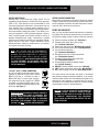
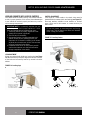
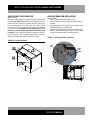
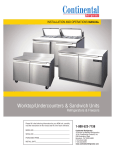
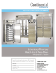
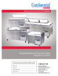
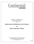
INSTALLATION AND OPERATIONS MANUAL Worktop and Undercounters Bar Equipment Bottle, Keg & Back Bar Coolers Glass & Plate Chillers Please fill in the following information for your NEW unit, carefully read the instructions in this manual and file it for future reference. MODEL NO. SERIAL NO. PURCHASED FROM INSTALL DATE 1-800-523-7138 Continental Refrigerator A Division of National Refrigeration & Air Conditioning Products, Inc. 539 Dunksferry Road Bensalem, PA 19020-5908 P 215-244-1400 F 215-244-9579 www.continentalrefrigerator.com TABLE OF CONTENTS Page Receiving Your New Model.............................................................................................................. 3 Uncrating Your New Model.............................................................................................................. 3 General Information and Important Operating Facts................................................................................. 3 Serial Data Tag........................................................................................................................................................3 Installation and Location................................................................................................................. 4 Ventilation...............................................................................................................................................................4 Floor Loads.............................................................................................................................................................5 Mounting and Leveling...........................................................................................................................................5 Condensate Removal..............................................................................................................................................5 Door Adjustment (KC & BBC Models)....................................................................................................................6 Initial Cleaning Procedure............................................................................................................... 6 Start-Up Procedure........................................................................................................................ 6 Electrical Connections.............................................................................................................................................6 GFI/GFCI Receptacles................................................................................................................................7 Start-Up Checklist...................................................................................................................................................7 Remote Applications...............................................................................................................................................8 Operation................................................................................................................................... 8 Refrigeration System and Adjustment....................................................................................................................8 Evaporator Assembly..............................................................................................................................................8 Interior Accessories...............................................................................................................................................................9 Shelving Installation (BBC - Back Bar Coolers)......................................................................................................9 Shelving Installation (CGC - Glass/Plate Chillers)..................................................................................................9 Wire Storage Bin Divider Installation......................................................................................................................9 Direct Draw Draft Beer Set-Up..............................................................................................................................10 Keg Tapping Instructions......................................................................................................................................10 Installation of CO2 Cylinder and Regulator............................................................................................................10 Maintenance............................................................................................................................... 11 Periodic Cleaning Procedure..................................................................................................................................11 General Preventative Maintenance.........................................................................................................................11 Care and Cleaning of Stainless Steel................................................................................................. 12 Parts and Service......................................................................................................................... 13 Placing a Service Call.............................................................................................................................................13 Obtaining Replacement Parts Under Warranty.......................................................................................................13 Obtaining Replacement Compressor Under Warranty............................................................................................13 Optional Accessories..................................................................................................................... 14 Installing Electric Condensate Heater.....................................................................................................................14 Sliding Glass Door Removal and Adjustment.........................................................................................................14 Installing Legs and Casters....................................................................................................................................15 Leveling Cabinets with Legs or Casters..................................................................................................................16 Leg Adjustment........................................................................................................................................16 Caster Adjustment....................................................................................................................................16 Padlock Hasp for Sliding........................................................................................................................................17 Auxiliary Drain Pan Installation..............................................................................................................................17 Remote Set-Up and Installation Guidelines............................................................................................................18 Limited Extended Protection Warranty................................................................................................ 19 Troubleshooting and Servicing Guide................................................................................................. 20 Wiring Diagrams.......................................................................................................................... 22 OPERATIONS MANUAL BOTTLE, KEG & BACK BAR COOLERS, GLASS & PLATE CHILLERS RECEIVING YOUR NEW MODEL Congratulations on your purchase of Continental Refrigerator superior bar equipment! When your shipment arrives, thoroughly examine the packaging for any punctures, dents, or signs of rough handling. It is in your best interest to partially remove or open the shipping container to examine the contents for any missing accessories or concealed damage which may have occurred during shipment. If the cabinet is damaged, it must be noted on the carrier’s delivery slip or bill of lading. A Freight Claim must be filed with the shipping company. FREIGHT DAMAGE IS NOT COVERED UNDER WARRANTY. UNCRATING YOUR NEW MODEL The shipping carton should remain on your cabinet to protect against dents or scratches while transporting to the actual set-up location. Remove the shipping container only at the last possible moment by using a pry bar to take out all the staples from around the bottom of the crate. Slide the cardboard carton up and off the unit, being careful not to rub against the cabinet. Remove any accessories or boxes on the skid or in the cabinet. Dispose of all packaging materials properly. GENERAL INFORMATION AND IMPORTANT OPERATING FACTS This manual has been compiled to aid in the installation, operation and maintenance of your new equipment. Please take the time to read it and familiarize yourself with your equipment and its operation, to enjoy optimum performance. Continental Refrigerator offers a variety of accessories for your model (see “Optional Accessories” section towards the back of this manual or contact your dealer for more information). SERIAL DATA TAG A serialized data tag is permanently attached to the inside righthand wall of your unit. (see Figure 1). In addition to identifying the specific product, this label provides important information regarding electrical requirements and refrigeration charge, as well as agency listings and factory contacts. FIGURE 1: Data Tag Four (4) bolts secure the cabinet to the wooden skid. The bolts are located at each end on the underside of the skid. In order to remove these bolts, tilt the cabinet backwards and place wooden blocks at each end in order to hold it in its tilted position. Using a ¾” socket or open end wrench, remove the bolts and carefully slide the cabinet off of the skid. If support plates are to be installed, save the bolts and washers (see “Mounting Caster/ Leg Support Plates” under “Optional Accessories”). After skid removal, the cabinet should never be moved without dollies or rollers to avoid damage to the cabinet bottom or floor. IMPORTANT NOTE: Do not under any circumstances, lay your new model on its front or sides. For a brief period of time, you may lay the cabinet on its back, but only when it’s properly blocked so as not to crush the back or end panels and also to allow provision for your hands, in order to set it in its upright position without damaging the cabinet. Do not plug in and operate model for at least three (3) hours after cabinet is set upright from being on its back as this can damage the compressor. IMPORTANT NOTE: The model and serial number should be noted on the front cover of this manual, in the spaces provided. If parts or service are ever needed for your unit, this information will be required to verify warranty status and to properly identify any parts that may be needed. OPERATIONS MANUAL 3 BOTTLE, KEG & BACK BAR COOLERS, GLASS & PLATE CHILLERS All cabinets must be given sufficient time to reach normal operating temperature before placing any food inside cabinet or pans (if equipped). For refrigerators, approximately 2 hours of operation is required to lower the cabinet temperature to 38°F (3°C). Freezers require approximately 2 hours of operation to lower the cabinet temperature to 5°F (-15°C) (see “Operation” section for further information). Prior to factory shipping, all products are performance-run tested for a minimum of 12 hours providing a highly sophisticated temperature recording exclusive to each individual cabinet. This recording is supplied within this manual packet. A final evaluation, including analysis of cabinet performance, leak check, vibration, noise level and visual examination is made by a qualified quality control team to assure a superior product. The carrier signs to this effect when they accept the product for shipping. To insure the maximum in safety and sanitation, all models are listed under the applicable standards of Underwriters Laboratories and the National Sanitation Foundation. VENTILATION The final location site of your air cooled refrigerator or freezer must provide a large quantity of cool, clean air. All refrigeration systems operate most efficiently and trouble-free with cool, dry air circulation. Avoid locations near heat and moisture generating equipment including ovens, cooking ranges, fryers, dishwashers, steam kettles, etc., or in direct sunlight (where temperatures can exceed 100°F). Do not select a location in an unheated room or area where temperatures may drop below 55°F. Air supply to the condensing unit is equally important. Restricting the air places an excessive heat load on the condensing unit and adversely affects its operation. Front Breathing models do not require any clearance around the the sides or back of the cabinet, since they take in and exhaust air under the cabinet and through the front grill, under the door. For optimum performance, the air flow under the cabinet and through the front grill cannot be restricted. INSTALLATION AND LOCATION Before moving the cabinet to its final point of installation, measure all doorways or passages to assure clearance. If additional clearance is needed, you can remove the cabinet doors (see “Removal of Doors and Door Adjustment”). IMPORTANT NOTE: To assure maximum operating efficiency, your new cabinet should be located where an unrestricted air supply can circulate under the cabinet and through the front grill . Do not at any time obstruct the grill area in the front of the cabinet in any way. These rules are essential for maximum cooling capacity and long life of refrigeration parts. FIGURE 2: Minimum Clearance Dimensions for Optimum Conditions CBC-CGC CLEARANCES BBC-KC CLEARANCES 4 OPERATIONS MANUAL 11/03/10 BOTTLE, KEG & BACK BAR COOLERS, GLASS & PLATE CHILLERS FLOOR LOADS CONDENSATE REMOVAL For example, a 20 cubic foot refrigerator can hold approximately 700 pounds of product (35 x 20). Assuming the cabinet itself weighs 300 pounds, the total combined weight of cabinet and product is approximately 1000 pounds. Therefore, the floor in this example must be able to support up to 1000 pounds. CBC Bottle Cooler models are provided with a floor drain in the storage compartment with a drain PAN hose located behind the front KC/BBC24 DRAIN INSTALLATION grill for easy disposal of condensate and water during cleaning. The floor at the final location site must be level, free of vibration and strong enough to support the total combined weights of your new model plus the maximum product load which might be placed into it. To estimate the possible product weight, assume that each cubic foot of storage space weighs approximately 35 pounds. Multiply 35 pounds by the amount of cubic feet in the cabinet to obtain the product load weight. MOUNTING AND LEVELING All Bar Equipment units contain a factory installed condensate drain water evaporating pan which is completely self contained and no further assembly or maintenance is required. On KC24 and BBC24 models, the drain pan and brackets must be attached by the installer (see Figure 3). For your convenience, only evaporator condensate drains into this pan and cabinet washout drainage water has its own hose located behind the front grill for easy disposal during cabinet cleaning. FIGURE 3: KC24/BBC24 Condensate Pan Install All Bar Equipment units are designed and constructed to be mounted directly on the floor without legs or casters (see Figure 2). When mounting directly to floor, the base of the cabinet should be sealed to the floor around its entire perimeter. IMPORTANT NOTE: It is extremely important that your new model is perfectly level for proper operation. If it is not level, the defrost water will fail to drain properly and will overflow the evaporator coil drain pan and into the cabinet of the model. After removing your unit from the skid, you may carefully slide it into position. Once the cabinet is positioned in its final location, check that it is level in all directions. If necessary, insert shims under the cabinet to make adjustments. Seal base of the cabinet to the floor around its entire perimeter with NSF approved sealant, to meet sanitation requirements. DRAIN PAN BRACKET DRAIN TUBE KEYSLOT OPERATIONS MANUAL MOUNTING SCREWS 5 BOTTLE, KEG & BACK BAR COOLERS, GLASS & PLATE CHILLERS DOOR ADJUSTMENT (KC & BBC Models) All doors are aligned at the factory, however vibration during transit may cause them to shift and realignment may be necessary. If the door(s) require realignment, proceed as follows (see Figure 4): 1. Open the door (90°) and loosen, but do not remove the mounting screws securing the top and bottom hinge brackets to the cabinet. 2. Adjust the door to desired position by hand or by tapping on the edge with a rubber mallet. KC - BBC DOOR HINGE 3. Securely tighten all mounting screws. 4. Check door alignment; repeat adjustment if necessary. FIGURE 4: KC/BBC Hinge Adjustment TOP HINGE BRACKET HINGE PIN INITIAL CLEANING PROCEDURE Prior to start-up and before placing any product inside of your new model, the interior of the cabinet should be thoroughly cleaned. Washing with a mild soap and warm water solution is recommended for cleaning the aluminum and stainless steel surfaces of your cabinet. This should be followed by cleaning with a baking soda solution (three (3) tablespoons of baking soda to each quart of warm water). Rinse thoroughly with clear water and dry with a clean, soft cloth. IMPORTANT NOTE: Never use harsh detergents, cleaners, scouring powders or chemicals when cleaning your model. Failure to dry the interior surfaces after cleaning may result in a streaking or staining of the metal. Complete cleaning procedures and precautions are listed in the (“Periodic Cleaning Procedure” under “Maintenance”). BUSHING START-UP PROCEDURE ELECTRICAL CONNECTIONS MOUNTING SCREW LEFT-HAND HINGED DOOR FIGURE 5: KC/BBC Door Components BACK BAR DOOR ASSEMBLY LOCK TONGUE SCREW (WHEN EQUIPPED) HANDLE SCREW HINGE BRACKET To insure proper operation, your new model must be connected to an individual circuit that can supply the full voltage as stated on the cabinet serial data plate. For correct voltage, power draw, and wire accommodations, check the data on the serial data plate located on the inner right wall of your new model. Verify that this information exactly matches the electrical characteristics at the installation location. An electrical wiring diagram, located on the inside compressor compartment rear, next to the electrical console box, should also be consulted during connection. For reference, a copy of each electrical wiring diagram is located towards the back of this manual (see “Wiring Diagrams” section). BUSHING LOCK (WHEN EQUIPPED) GASKET Refrigeration compressors are designed to operate within +/-10% of the rated voltage indicated on the cabinet serial plate. Excessively high or low supply power can burnout the compressor. This can be easily detected and will void the factory warranty. Full voltage at the correct rating, on a separate, designated circuit, not affected by the operation of other electrical appliances, must be available to the refrigeration unit at all times. Extension cords should never be used on commercial equipment, as they can overheat and/or result in low voltage. BUSHING SCREW 6 HINGE BRACKET OPERATIONS MANUAL BOTTLE, KEG & BACK BAR COOLERS, GLASS & PLATE CHILLERS GFI/GFCI RECEPTACLES Building codes in some areas may require certain 115 volt receptacles to be protected by a Ground-Fault Circuit Interrupter (GFCI or GFI). These devices are not recommended for most commercial refrigerators and freezers, since nuisance trips can occur (typically due to moisture) causing temporary loss of power. This may result in intermittently high storage temperatures and potentially unsafe food product. If you decide to connect your equipment to a GFCI protected receptacle, a properly sized, commercial grade circuit breaker should be used on a separate, designated power supply. Alternatively, a qualified electrician may be able to hard wire your equipment, eliminating the need for a GFCI device. Contact Continental’s Service Department before making any modifications to your cabinet, to avoid loss of warranty coverage. NOTE: GFCI DEVICES ARE NOT RECOMMENDED. PRODUCT LOSS AND/OR PROBLEMS RESULTING FROM NUISANCE TRIPS OR CONNECTION TO A DEFECTIVE OR IMPROPER POWER SUPPLY, ARE NOT COVERED UNDER WARRANTY. UNAUTHORIZED MODIFICATIONS TO YOUR EQUIPMENT OR THE POWER CORD CAN CAUSE AN ELECTRICAL HAZARD AND WILL VOID THE FACTORY WARRANTY. 115 VOLT, 60 HZ, 1 PHASE CONNECTION All 115 volt models are provided with a factory installed, UL approved 15-amp power cord and NEMA 5-15P plug, or a 20-amp cord with a NEMA 5-20P plug. To insure proper operation, this equipment must be plugged into a NEMA compatible, grounded receptacle that can supply the full voltage and amperage stated on the serial plate (see Figure 1). IMPORTANT NOTE: A SEPARATE, ISOLATED, PROPERLY SIZED POWER SUPPLY MUST BE PROVIDED. GFCI DEVICES AND/OR EXTENSION CORDS SHOULD NOT BE USED. PRODUCT LOSS, AS WELL AS PROBLEMS RESULTING FROM NUISANCE TRIPS OR HIGH/LOW VOLTAGE, ARE NOT COVERED UNDER WARRANTY. SPECIAL VOLTAGE CONNECTIONS When models are ordered from the factory with special, optional voltages, connections should be made as required on the electrical wiring diagram provided on the inside compressor compartment rear next to the electrical console box. START-UP CHECKLIST After your unit has been installed and electrically connected in accordance with this manual, please take time to check the following before loading product, to assure trouble free operation: Sufficient clearance provided (see “Ventilation”) Seperate power supply with correct voltage (see “Electrical Connections”) Cabinet level and sealed (see “Mounting and Leveling”) Doors close and seal properly (see “Door Adjustment”) Correct cabinet temperature (see “System and Adjustment”) Refrigeration lines free of kinks and vibration (see “Refrigeration System”) Condenser and evaporator fans rotate freely (see “Refrigeration System”) All packaging discarded and cabinet cleaned (see “Periodic Cleaning”) BBC/CGC: Shelves installed correctly (see “Shelving”) CBC: Dividers installed with springs (see “Wire Dividers”) KC: Towers and kegs correct (see “Direct Draw Set-Up”) The system should run smoothly and quietly in accordance with generally accepted commercial standards. If any unusual noises are heard, turn the unit off immediately and check for any obstructions of the condenser or evaporator fans. Fan motors, fan blades, or fan housings can be jarred out of position through rough handling in transit or during installation. CAUTION: IF UNIT IS UNPLUGGED OR DISCONNECTED FOR ANY REASON, ALLOW 5-6 MINUTES BEFORE TURNING THE UNIT BACK ON TO ALLOW THE SYSTEM TO EQUALIZE. DISREGARDING THIS PROCEDURE COULD CAUSE AN OVERLOAD AND PREVENT THE UNIT FROM OPERATING. 09/03/10 OPERATIONS MANUAL 7 BOTTLE, KEG & BACK BAR COOLERS, GLASS & PLATE CHILLERS FIGURE 6A: CBC Component Location REMOTE APPLICATIONS All products are available for purchase as remote models, in which case the condensing unit is not supplied with the cabinet. All remote models come standard with an expansion valve in the evaporator housing, as well as stubs for the liquid and suction refrigeration line connections. Installation of the refrigeration accessories, condensing unit, and electrical hook-up should be performed by qualified refrigeration personnel of a competent refrigeration company only (see “Remote Set-Up and Installation Guidelines” under “Optional Accessories”). OPERATION All cabinets must be given sufficient time to reach normal operating temperature before placing any product inside. Refrigerated bottle coolers are designed to maintain cabinet temperature of 34°F to 38°F (1°C to 3°C) and approximately 3 hours of operation are required to reach this temperature. FIGURE 6B: CGC Component Location REFRIGERATION SYSTEM AND ADJUSTMENT The temperature control is accessible inside the cabinet, on the back wall in front of the evaporator coil (see Figure 6, 6A & 6B). If an adjustment is necessary to maintain the above temperature range only, place a screwdriver into the thermostat slot and turn clockwise for a colder cabinet temperature or counterclockwise for a warmer cabinet temperature. Further adjustments out of the factory design temperature range must be made by a qualified refrigeration mechanic only. FIGURE 6: KC/BBC Component Location EVAPORATOR ASSEMBLY All models have an easily accessible, performance-rated, full length, extra large, coated fin-type coil for extended life, with a uniquely directed air flow distribution that keeps product at uniformly constant temperatures (see Figure 6 & 6A). 8 OPERATIONS MANUAL IMPORTANT NOTE: All refrigerators have an automatic, “off-cycle” defrost system, which means defrosting occurs when the compressor is not operating during an off-cycle. Do not set the temperature below 35°F (1.7°C) because the evaporator will become blocked by ice, due to shorter off-cycles. This can result in loss of product in the cabinet and require manually defrosting your unit and re-adjusting the temperature control. BOTTLE, KEG & BACK BAR COOLERS, GLASS & PLATE CHILLERS INTERIOR ACCESSORIES SHELF INSTALLATION (BBC - Back Bar Coolers) BBC models are shipped with (2) shelves per section and (4) clips for each shelf (see Figure 7A for arrangements). Pilaster strips are secured to the cabinet walls with special screws which allow the strips to be easily removed for cleaning without the use of tools. To install a shelf, simply insert the clips into the pilasters at the desired shelf location FIGURE 7: Standard Shelf Pilaster and place the shelf on the clips (see Figure 7). FIGURE 7A: Shelf Layouts WIRE STORAGE BIN DIVIDER INSTALLATION (Bottle Coolers) The standard accessory package that is supplied from the factory with your bottle cooler consists of: MODEL SMALL DIVIDER LARGE DIVEDER MOUNTING SPRINGS CAP CATCHER CBC37 1 1 2 1 CBC50 1 2 3 1 CBC64 1 3 4 1 CBC95 2 7 9 2 A mounting spring is provided for each bin divider (see Figure 8) to keep it in place. Before installing bin dividers, determine the desired spacing needed for product loading, then disconnect the cabinet from the power supply. The small dividers are provided for installation in front of the fan motor (see Figure 6A). To install the small divider, position it as shown and place a mounting spring over the long extension wire. Insert the extension wire into one of the bushing holes in the fan cover and push the divider towards the cover, compressing the spring. Grasp the divider securely and insert the front extension wire into the corresponding bushing hole on the interior front wall of the cabinet. Gently release the divider and the spring will keep it in place. Check that the divider is straight front-to-back. Install the large bin dividers in the same manner, but in their respective bushing holes in the evaporator cover at the back of the cabinet interior. After all dividers are installed, reconnect power to your cabinet. IMPORTANT WARNING: Always disconnect power to your bottle cooler when installing or removing the small bin divider since the long extension on the divider may interfere with the fan , causing damage to your unit. Also keep bottles, labels, debris, etc. away from the underside of the fan housing, to avoid blocking the fan blade. THIS CAN RESULT IN PREMATURE FAILURE AND VOID YOUR WARRANTY. FIGURE 8: CBC Bin Dividers SHELF INSTALLATION (CGC - Glass/Plate Chillers) CGC24 & CGC37 models are shipped with 2 shelves (1 for upper and 1 for lower position). CGC50 models have 4 shelves (2 upper and 2 lower). Support angles come secured to the front and back walls of the cabinet (see Figure 6B) for the upper and lower positions. The supports allow the shelves to slide side-to-side, for access to product below them. Install the shelf in the lower position first by placing it in the cabinet with the shelf wires running front-to-back and simply setting it down on the lower support angles. Repeat this procedure for the upper position. OPERATIONS MANUAL 9 BOTTLE, KEG & BACK BAR COOLERS, GLASS & PLATE CHILLERS Keg Cooler Capacities No. of Doors Net Capacity (Cu. Ft.) Barrel-Type Keg Qty. Straight-Wall Keg Qty. KC24 1 8 1 1 KC50 2 16 - 2 KC50S 2 13 - 2 Model KC59 2 22 2 3 KC59S 2 15 2 2 KC69 2 26 3 3 KC69S 2 18 3 3 KC79 3 28 4 4 KC79S 3 22 3 3 KC90 3 35 4 5 KC90S 3 25 4 4 KEG TAPPING INSTRUCTIONS Because keg and tap types vary from brand to brand, contact your beer distributor for specific keg tapping instructions. INSTALLATION OF CO2 CYLINDER AND REGULATOR Pressurized CO2 should be provided from outside the cabinet. The supply hose can be routed through the access hole at the back of the machine compartment and into the cabinet through the knock-out plug located on the upper side wall (see Figure 9). The CO2 dispensing gas must be reduced to 8-10 PSI by a regulator (not supplied) and delivered to the manifold splitter (on the left upper wall of cabinet) using the supplied hose and clamps. Cut hose to length. The manifold splitter will separate the gas into two or more lines to supply each keg tap. A check valve on the manifold splitter prevents beer from backing up into the supply hose and regulator. DIRECT DRAW DRAFT BEER SET-UP (Keg Coolers) Your new unit will provide cold storage for barrel-type or straight-side kegs (see Table above for capacities). To install dispensing towers (see Figure 9), place a rubber washer over tower mounting holes in the top of the cabinet and secure tower(s) using fine thread machine screws supplied in cabinet top (do not use wood screws supplied with tower). The hose line from tower must go through hole in top and be attached to the keg tap (supplied by others). Install the cold air tubes from inside the cabinet by pushing each tube as far as it will go into its closest tower hole. About 8” of tube will feed into the tower. IMPORTANT NOTE: Changing Kegs: defrosting of all keg coolers is automatic, but since loading times vary, unplug the cabinet and leave the doors open for at least 15 minutes during keg change, to keep ice from accumulating on the evaporator coil. The temperature control (on the left rear interior) is factory set to maintain keg temperatures within 35°F to 40°F under normal conditions. It may take several hours to cool a warm keg, so cold kegs should be moved from chilled storage immediately into your cabinet, to avoid warm or spoiled product. Before a new barrel is tapped, purge CO2 lines by quickly opening and closing the outlet valve, allowing a surge of gas to travel through the line and tap. NOTE: Proper cleaning is extremely important for the beer For your convenience, a cleanout drain hose is provided from faucet, drain pan and any items coming in contact with food the behind the front grill with 3 ft. of hose for an external drain or beverages, COOLER SET-UP to prevent odors and tastes from bacteria. It is connection to be made by installer. If a beer waste jar KEG is to be normal for some sweating on or around each draft tower and installed, the drain line (on the left front interior floor) can be cut. door opening, under conditions of high humidity. FIGURE 9: Typical Keg Cooler Tap Set-Up DISPENSING TOWER w/COOLING HOSE MANIFOLD SPLITTER KNOCKOUT HOLE FOR HOSE ACCESS COLD AIR HOSE KEG TAPS (BY OTHERS) REGULATOR (BY OTHERS) KEGS (BY OTHERS) CO2 TANK (BY OTHERS) CO2 HOSES (BY OTHERS) 10 OPERATIONS MANUAL BOTTLE, KEG & BACK BAR COOLERS, GLASS & PLATE CHILLERS MAINTENANCE SAFETY PRECAUTIONS THE FOLLOWING SAFEGUARDS SHOULD BE FOLLOWED WHEN OPERATING ANY APPLIANCES: DISCONNECT THE POWER CORD BEFORE ATTEMPTING TO WORK ON OR CLEAN EQUIPMENT. DO NOT ATTEMPT TO REMOVE ANY COVERS OR PARTS YOURSELF, AS THIS CAN EXPOSE DANGEROUS, HIGH VOLTAGE WIRING. SERVICE SHOULD ONLY BE PERFORMED BY A QUALIFIED TECHNICIAN. ALWAYS ROUTE POWER CORDS AWAY FROM AREAS WHERE THEY CAN BE WALKED ON OR DAMAGED BY OTHER EQUIPMENT. NEVER USE EXTENSION CORDS OR PLUG MORE THAN ONE APPLIANCE INTO THE SAME CIRCUIT. THIS CAN OVERLOAD THE POWER SUPPLY, WHICH CAN RESULT IN ELECTRICAL SHOCK OR FIRE. YOUR APPLIANCE IS EQUIPPED WITH A POLARIZED, GROUNDED POWER PLUG. NEVER ATTEMPT TO REMOVE THE GROUND POST OR USE A NON-POLARIZED ADAPTER, WITHOUT PROPERLY GROUNDING THE EQUIPMENT. IF A REPLACEMENT PART IS REQUIRED, ALWAYS INSIST ON FACTORY AUTHORIZED COMPONENTS. PERIODIC CLEANING PROCEDURE It is always best to clean your refrigerator or freezer when the product load in your cabinet is as its lowest level. To clean the interior or exterior cabinet surfaces, follow these procedures: 1. Disconnect your cabinet from its power supply, remove all product from inside and temporarily move it to a walk-in or other refrigerated storage. 2. Open all doors and allow the cabinet to reach room temperature. Remove all accessories (shelves, racks, pilasters, clips, etc.) from inside and wash them with a baking soda and warm water solution, rinse thoroughly with clean water. Dry all accessories completely with a soft clean cloth. 3. Once the cabinet has reached room temperature, wash all inside and outside surfaces with a solution of warm water and baking soda. Pay particular attention to the face of the cabinet, as any residue or debris can impair the door seal. For slightly more difficult cleanups, ammonia or vinegar in warm water can be used. Rinse thoroughly with clear water and dry with a soft clean cloth. Carefully wash all of the vinyl door gaskets with clean water, dry them and check for any damage, which may affect the seal. Failure to dry all surfaces completely may cause water stains or streaking on the aluminum or stainless steel finish. 4. Return all accessories to their original locations, reconnect the power. Wait at least 1 hour before reloading product. PRECAUTIONS NEVER USE HARSH DETERGENTS, CLEANERS, SCOURING POWDERS, OR CHEMICALS WITH BLEACH WHEN CLEANING YOUR UNIT. GENERAL PREVENTATIVE MAINTENANCE The most important thing you can do to maintain any refrigerator or freezer and extend its life, is to keep the condenser clean. Performance of the air-cooled condensing unit, located on top of the cabinet, depends exclusively upon the amount of air passing through the condenser fins. Your refrigerator or freezer will run more efficiently, consume less energy, and provide a maximum of trouble-free service throughout its lifetime if the condenser is kept clean and an adequate supply of clean, cool air is provided at all times. At least once a month inspect the condenser coil, located behind the front grill, to check for debris or blockage. To remove the front grill from KC and BBC models (see Figure 6), remove the (2) screws located at the bottom of the grill. Lift the grill up and away from the cabinet. To remove the front grill on CBC models (see Figure 6A), remove the (4) screws (2 on each side of the grill). Lift the grill away from the cabinet. If the condenser coil is dirty or blocked, disconnect the cabinet power supply and using a stiff brush, carefully wipe away any dirt and debris from the condenser fins. Using a vacuum cleaner with a brush attachment may aid in this process. After cleaning, make sure you can see clearly through the condenser, then restore electrical power to your model. CAUTION: CONDENSER FIN PLATES ARE MADE FROM THIN METAL AND HAVE SHARP EDGES. ALWAYS WEAR GLOVES. USE CAUTION WHEN WORKING ON OR AROUND THE CONDENSING UNIT TO PREVENT CUTS AND AVOID DAMAGING FINS, TUBING AND OTHER COMPONENTS. FAILURE TO PROPERLY CLEAN THE CONDENSER REGULARLY WILL CAUSE EXESSIVE COMPRESSOR LOAD, REDUCING THE PERFORMANCE AND EFFICIENCY OF YOUR UNIT. THIS CAN RESULT IN PREMATURE FAILURE AND VOID YOUR WARRANTY. OPERATIONS MANUAL 11 BOTTLE, KEG & BACK BAR COOLERS, GLASS & PLATE CHILLERS CARE AND CLEANING OF STAINLESS STEEL* *Some information and graphics for this section were obtained from “Stainless Steel Equipment Care and Cleaning” brochure, published by the North American Association of Food Equipment Manufacturers (NAFEM). DO NOT USE: abrasive cleaners, chemicals with chlorides or muriatic acid to clean your equipment. Contrary to popular beliefs, stainless steel can rust, if not properly cared for and maintained (That’s why it’s called stain-LESS steel, not stain-PROOF steel.) All steel is primarily made of iron. Stainless steels contain other metals, such as chromium and nickel, that provide an invisible film on the surface of the steel that acts as a shield against corrosion. As long as this invisible layer is intact and not broken or contaminated, the metal will retain its corrosion protection and remain stain-less. 3. HARD WATER causes spots and stains on stainless steel surfaces, particularly when it is heated. Find out the hardness of your water and treat it properly, if needed. Use a water filter and softeners if you have hard water. Club soda can be used to remove streaks or spots. There are 3 basic things that can break down the protective layer on your stainless steel, which must be avoided: 1. MECHANICAL ABRASION is caused by things that scratch the surface of the metal. Only use soft cloths or plastic scouring pads to clean and always scrub in the same directions as the metal grain. DO NOT USE: hot or hard water to clean stainless steel. CLEAN YOUR STAINLESS STEEL REGULARLY using the proper tools and cleaners. After cleaning, always rinse, rinse, rinse thoroughly with cool, clean, clear water. CHECK ALL OF YOUR EQUIPMENT PERIODICALLY. If you see any signs of rust, clean the area immediately, with a plastic scrubbing pad. If surface rust is removed promptly, permanent corrosion, pits and cracks may be avoided. Special stainless steel polishes, that can help restore the protective coating on your equipment, are available from a variety of retailers. DO NOT USE: steel pads, wire brushes, scrapers or knives to clean your equipment. 2. CHLORIDES are found in water, salt, food and worst of all, many cleaners. Only use chloride-free, alkalinebased, non-abrasive cleaners. Always rinse thoroughly with cool, clean water and dry with a soft towel. A solution of 1 tablespoon baking soda mixed with 1 pint water can be used to remove tough stains. 12 OPERATIONS MANUAL IMPORTANT: If these recommendations are not followed, the protective film on your stainless steel can break down and your equipment may begin the long walk down the dark road of corrosion. BOTTLE, KEG & BACK BAR COOLERS, GLASS & PLATE CHILLERS PARTS AND SERVICE Continental is committed to providing the best customer service in the industry. All new units come with a Limited Extended Protection Warranty (see “Warranty” section of this manual for details). If a problem arises with your equipment, please contact our Service Department at 1-800-523-7138 (extension 3301, 3302, or 3303). One of our Service Specialists will do everything possible to solve the problem as quickly as possible. ITEMS NOT COVERED UNDER WARRANTY INCLUDE, BUT ARE NOT LIMITED TO: OBTAINING REPLACEMENT PARTS UNDER WARRANTY If replacement parts are required for a unit under warranty, contact Continental’s Service Department. New parts will be sent from the factory and, when applicable, a Return Goods Authorization (RGA) will be issued to return old parts. The RGA number must appear on the packaging of any parts returned, or they will not be accepted. If a service agent uses a part from their stock, Continental will replace it with a factory part. OBTAINING REPLACEMENT COMPRESSOR UNDER WARRANTY • Preventative maintenance: cleaning condenser coils and other components. • Consumables: light bulbs, door gaskets, batteries. General hardware adjustments: cabinet leveling, casters/legs, doors/hinges. • Problems due to: inadequate installation or supply power; improper maintenance, operation, or abuse. • Compressor failure due to: dirty condenser, insufficient clearance/ventilation, excessive temperatures. • System adjustments and calibrations, including: controls, thermometer and expansion valves. If the compressor should fail within the first twelve (12) months of use, or within twenty (20) months from the date code on the compressor, an “over-the-counter” exchange must be made at an authorized Copeland, Danfoss, Embraco, or Tecumseh wholesaler. Consult the Table of Contents in the front of this manual for detailed information on the items listed above. Contact Continental’s Service Department with any additional questions. • Continental will supply a replacement compressor at no charge and pay for regular freight. (If expedited freight is requested, the end user, dealer or service agent is responsible for additional charges and must provide credit card information. • A compressor can be purchased locally and Continental will either replace the stock unit with a new factory compressor, or offer an allowance towards the purchase of a replacement compressor, up to: $100 for 1/5hp to 1/3hp; $250 for 1/2hp to 3/4hp; $350 for 1hp to 2hp. PLACING A SERVICE CALL In order to receive prompt service, always be prepared to provide your: cabinet model and serial number; cabinet location name and date installed; contact name and phone number; plus a description of the problem. During normal business hours (Monday to Friday, 8am to 5pm Eastern) contact the Service Department at: 1-800-523-7138 (extension 3301, 3302, or 3303) prior to any warranty service work being performed. After the first year, the compressor motor is covered under an extended “parts only” warranty. The customer is responsible for any labor charges and any additional parts that may be required. Contact the Service Department to obtain a replacement compressor through one of the following methods: The data tag from the defective compressor (or compressor model, serial number and date code, if the tag cannot be removed) must be included with any reimbursement request. After normal business hours, or on weekends, notify our Service Department by sending an email to: [email protected], or leaving a voice message at: 1-800-523-7138 (extension 3301). Be sure to provide the information listed above. Contact Continental the following business day, during normal business hours, to verify the status of your call. OPERATIONS MANUAL 13 BOTTLE, KEG & BACK BAR COOLERS, GLASS & PLATE CHILLERS OPTIONAL ACCESSORIES Continental offers a variety of accessories for your unit. INSTALLING ELECTRIC CONDENSATE HEATER The electric condensate heater has a power cord with a 15 amp plug attached. To install the heater on a KC or BBC model, disconnect the power supply by unplugging the cabinet electrical cord. Remove the grill from the front of the cabinet (see Figure 10) and carefully set it aside. For easier access to the machine compartments, the louvered end panel can also be removed. Place the electric heater in the upper machine compartment as shown and carefully position the end of the plastic drain tube into the heater pan. Make sure the tubing is not blocked or kinked and that the end is located securely, so any water running out of the tube will go into the pan. Route the heater power cord through to the lower machine compartment. Plug the cord into the receptacle labeled “vaporizer” located on the wall between the cabinet and the machine compartment. Secure any excess power cord with a wire tie, so it is away from hot or moving parts and does not fall into the pan or under the cabinet. Reattach the front grill and the end panel. Plug the cabinet electrical cord into the power supply. SLIDING GLASS DOOR REMOVAL AND ADJUSTMENT All sliding glass doors are easily removable for thorough cleaning. To remove the doors, slide the outer door (see Figure 11) open about half way, grasp the door on both sides and lift straight up, off the bottom of the mounting frame. Tilt the bottom of the door out, so it clears the frame. Slide the door towards its closed position, to release tension on the springloaded door closer in the top of the mounting frame. Gently set the door down in a safe location. Repeat this procedure for the inner door. To replace the doors, reverse the steps above, making sure the pusher on the spring-loaded door closer seats properly against the top of the door. If your sliding door does not close firmly, remove the doors, starting with the outer door, as described above. Check the bottom of the door, mounting frame channel, and rollers to make sure they are clean and free of debris. If the rollers are damaged or do not turn freely, contact the factory to order replacement parts. IMPORTANT NOTE: It is extremely important to ensure the condensate heater is plugged into the receptacle labeled “vaporizer” and that the condensing unit is plugged into the receptacle labeled “condensing unit.” IMPORTANT NOTE: The glass used in sliding or hinged glass doors is special, thermally sealed and cannot be replaced with ordinary window or plate glass. Replacement glass can be ordered directly from the factory. FIGURE 11: Sliding Glass Door Components BACKBAR SLIDING GLASS DOOR ASSEMBLY FIGURE 10: Electric Condensate Heater MOUNTING FRAME SPRING-LOADED DOOR CLOSERS DOOR SEAL INTEGRAL HANDLE 14 LEFT HAND (INNER) DOOR RIGHT HAND (OUTER) DOOR OPERATIONS MANUAL DOOR SEAL INTEGRAL HANDLE BOTTLE, KEG & BACK BAR COOLERS, GLASS & PLATE CHILLERS INSTALLING LEGS OR CASTERS If your new unit is supplied with optional legs or swivel casters, they will be packed in the accessory box that came with your cabinet. Legs or casters should only be installed only when the cabinet is close to its final location. IMPORTANT: Make sure your legs or casters are tightened extremely well after installation, otherwise the cabinet will be unstable and may sway or rock, which can damage your unit. the large hole in the plate lines up with the threaded hole under the compressor compartment. Screw the threaded end of a leg or caster through the hole in the plate and into the threaded hole under the compressor compartment. Fasten the other end of the plate to the threaded hole under the storage compartment cabinet with a bolt and washer (supplied with the original cabinet crating). Screw another leg or caster into the threaded hole under the storage compartment, at the opposite end of the cabinet. Tilt the cabinet in the opposite direction and install the remaining support plate and legs or casters. KC & BBC MODELS FIGURE 12: Installation of Legs or Casters To install legs or casters, place wooden blocks along the back, CBC24, CBC64 & CBC95 at each end. Tilt the cabinet back, using the wood blocks to help hold the cabinet in its tilted position. Locate the large threaded holes in the bottom of the cabinet and simply screw the threaded studs on your legs or casters into the threaded holes. Repeat this procedure by tilting the cabinet in the opposite direction and installing the remaining legs or casters. CBC MODELS Follow the steps below for your cabinet. Models purchased with optional legs or casters are provided with: CBC24 & CBC64 (4) Legs or Casters CBC37 & CBC50 (4) Legs or Casters, plus (2) Support Plates (shipped loose) CBC95 (6) Legs or Casters CBC24 & CBC64 MODELS Install your (4) legs or casters under the refrigerated storage compartment of your cabinet by placing wooden blocks along the back, at each end. Tilt the cabinet back, using the wood blocks to help hold the cabinet in its tilted position. Locate the proper threaded holes along the bottom front of your cabinet FIGURE 13: Installation of Legs or Casters - CBC37 & CBC50 (see Figure 12). Screw the threaded studs on your legs or casters into the holes as shown. Repeat this procedure by tilting the cabinet in the opposite direction and installing the remaining legs or casters. CBC95 MODEL Follow the steps above to install (6) legs or casters under the storage compartment, as shown (see Figure 12). CBC37 & CBC50 MODELS For maximum stability, (2) support plates are provided and must be attached from under the storage compartment to the bottom of the compressor compartment (see Figure 13). To install legs or casters on these models, place wooden blocks along the back, at each end. Tilt the cabinet back so the blocks help support the cabinet. Position one support plate as shown so OPERATIONS MANUAL 15 BOTTLE, KEG & BACK BAR COOLERS, GLASS & PLATE CHILLERS LEVELING CABINETS WITH LEGS OR CASTERS Your cabinet must be leveled correctly, front-to-back and sideto-side, for proper operation. If it is not level, the condensate pan in your cabinet will not drain properly and water may overflow into the storage compartment. IMPORTANT NOTE: It is extremely important that your cabinet is perfectly level for proper operation. If it is not level, the following adverse conditions may occur: 1. The door(s) will not be properly aligned and consequently will not provide a good seal. 2. Your unit may run excessively. 3. An excessive amount of ice will accumulate in the cabinet, around the door opening(s) and on the evaporator coil. If allowed to continue, ice will eventually block the coil and the unit will fail. This can result in loss of food stored in the cabinet. 4. Condensate water will fail to drain properly and will overflow the evaporator coil drain pan and into the storage compartment of the cabinet. CASTER ADJUSTMENT If the height of a caster needs to be raised, shims must be installed under the casters which need leveling (see Figure 15). Extra-large washers, available at most hardware or furniture stores, can be used to shim casters, or contact the factory for caster shims. LEG ADJUSTMENT All legs are equipped with bullet-type leveling feet (see Figure 14). Wood blocks may be used to support the cabinet, as shown, so the bolts can be turned by hand or by wrench to level the A cabinet. Do not level casters by unscrewing them and leaving them loose. This will damage the cabinet and threaded holes, voiding your warranty. FIGURE 15: Leveling Casters CASTER INSTALLATION OPTIONAL CASTER SHIM (CM1-2476) CASTER BLOCKS FIGURE 14: LevelingLEG Legs INSTALLATION THREADED END LEG TURN FOOT CLOCKWISE TO REDUCE HEIGHT, OR COUNTERCLOCKWISE TO INCREASE HEIGHT. BLOCKS 04/29/10 16 OPERATIONS MANUAL BOTTLE, KEG & BACK BAR COOLERS, GLASS & PLATE CHILLERS PADLOCK HASP FOR SLIDING LIDS (Bottle Coolers) Disconnect power supply from cabinet. Place lock plate through lid handle (see Figure 16) and position lock keeper over end of plate. Use holes in keeper as a template to mark (2) hole locations on front ledge of your bottle cooler. Use a short drill bit to make (2) 1/8” holes in the front top edge of the cabinet at the locations marked. DO NOT drill any deeper than 1/4” into cabinet top, to avoid damaging wiring and refrigeration lines in cabinet. Position keeper and attach to cabinet with (2) tamper-proof screws. Place lock plate through handle and keeper. Secure with padlock (by others) through hole in plate. AUXILIARY DRAIN PAN INSTALLATION (Bottle Coolers) 1. Remove standard refrigeration/drain cover. 2. Remove plastic tubing from drain tube. Keep tubing for new pan. 3. Feed plastic tubing onto new drain pan, and push all tubAUXILIARY DRAIN PAN INSTALLATION ing through drain hole in interior side. 4. Mount new refrigeration cover over new drain pan, and secure to interior side using existing hole. Finish installation with self taping screws in remaining 3 holes. FIGURE 17: Auxiliary Drain Pan Installation FIGURE 16: Padlock Installation DRAIN HOLE DRAIN TUBE TUBING PAN COVER 11/02/10 OPERATIONS MANUAL 17 BOTTLE, KEG & BACK BAR COOLERS, GLASS & PLATE CHILLERS REMOTE SET-UP AND INSTALLATION GUIDELINES All remote refrigerators and freezers are shipped with an expansion valve, thermostat and defrost timer (freezer only), installed from the factory. The installer is responsible for connecting all refrigerant lines, liquid line drier, sight glass, solenoid, head pressure control, hi/low pressure safety, crankcase heater, condensing unit and any other accessories as well as wiring. The evaporator section has been factory leak checked with helium, however; due to vibration in transit, the entire system must be thoroughly leak checked after installation and prior to start-up. The final leak inspection of the entire completed refrigeration system and all of its components as well as start-up and the operation of the refrigeration system is the sole responsibility of the installer. The CFC-Free refrigerant used in standard remote and selfcontained models is R-134a for refrigerators and R-404a for freezers. All compressors and systems designed for these refrigerants utilize polyolester oil as their main lubricant, which absorbs moisture from the ambient surroundings extremely fast and in much greater quantity than conventional mineral oils. large pressure differential between the system and the vacuum pump. System must be evacuated from both high and low sides of the system using heavy duty vacuum hoses. 6. Each system should be charged with the refrigerant type as specified on the cabinet data tag. This refrigerant type should match the type listed on the condensing unit being used. The refrigerant charge should be held to the minimum required for the satisfactory pull down and operation. For an accurate indication of refrigerant charge, the sight glass will show a full column of liquid. 7. The superheat reading taken 6” from the compressor suction valve should be 30° +/- 5°. Expansion valve adjustment may be necessary to achieve this superheat. 8. Installation of the electric condensate heater is the responsibility of the installer (see “Installing Electric Condensate Heater” under “Optional Accessories”). Since moisture levels greater than 100 PPM will result in system corrosion and ultimate failure, it is imperative that the compressor, components and entire system be kept sealed. CAUTION: EXTREME CARE MUST BE USED WHEN ACCESSING THE SYSTEM DURING INSTALLATION. DUE TO THE COMPLEXITY OF REMOTE REFRIGERATION SYSTEMS AND THE POTENTIAL FOR IMPROPER INSTALLATION, ANY RESTRICTIONS, LEAKS, FAILED OR DAMAGED COMPONENTS CAUSED BY CONTAMINANTS ARE NOT THE RESPONSIBILITY OF CONTINENTAL REFRIGERATOR. 1. All refrigerant lines and components must be clean, free of burrs and purged with nitrogen prior to and during brazing or soldering connections. Nitrogen purging during brazing or soldering will eliminate carbon or foreign matter contamination. Any system restrictions or contamination is the responsibility of the installer. 2. Condensing unit or compressor shall not be left open to the atmosphere for more than five (5) minutes. 3. No refrigeration component, tubing or fitting shall be left open to the atmosphere for more than ½ hour without being soldered, capped or plugged. 4. Each completed refrigeration system shall be purged with 150psi of dry nitrogen for at least six (6) seconds, then pressurized with at least 165psi of nitrogen for pressure check (making sure to energize any solenoid valves to assure access). Leak-check all joints, flare fittings and valves and make sure there is no pressure drop within the system. 5. System evacuation is of the utmost importance with NONCFC refrigerant systems. System must be evacuated to a minimum of 200 microns. In addition, a vacuum decay test is strongly recommended to assure there is not a 18 OPERATIONS MANUAL BOTTLE, KEG & BACK BAR COOLERS, GLASS & PLATE CHILLERS THREE (3) YEAR PARTS AND LABOR WARRANTY Continental Refrigerator warrants to the original purchaser of every new Continental Refrigerator self contained unit, including all parts thereof, that such equipment is free from defects in material and workmanship, under normal use, proper maintenance and service as indicated by Continental Refrigerator installation and operation manual, for a period of three (3) years from the date of installation, or thirty-nine (39) months from the date of shipment from the manufacturer, whichever comes first. Normal wear type parts, such as light bulbs/lamps and gaskets are not covered by this warranty. For the purpose of this warranty, the original purchaser shall be deemed to mean the individual or company for whom the product was originally installed. Continental Refrigerators obligation under this warranty shall be limited to repairing or replacing, including labor, any part of such product which proves thus defective. Continental Refrigerator reserves the right to examine any product claimed to be defective. The labor warranty shall be for self-contained units only and for standard straight time, which is defined as normal service rate time, for service performed during normal working hours. Any service requested outside of a servicer’s normal working hours will be covered under this warranty for the normal rate and any additional overtime rate will be the responsibility of the equipment purchaser. Any part determined to be defective in the product should be returned to the company within thirty (30) days under the terms of this warranty and must be accompanied by the cabinet model, serial number, and identified with a return material authorization number, issued by the manufacturer. Special installation/applications, including remote locations, are limited in coverage by this warranty. Any installation that requires extra work, and/or travel, to gain access to the unit for service is the sole responsibility of the equipment purchaser. Improper operation resulting from factors, including but not limited to, improper or negligent cleaning and maintenance, low voltage conditions, inadequate wiring, and accidental damage are not manufacturing defects and are strictly the responsibility of the purchaser. Condenser coils must be cleaned at regular intervals. Failure to do so can cause compressor malfunction and will void warranty. Continental Refrigerator recommends a minimum monthly cleaning, as stated in the installation and operation manual. ADDITIONAL TWO (2) YEAR COMPRESSOR PART WARRANTY In addition to the warranty set forth above, Continental Refrigerator warrants the hermetically/semi-hermetically sealed compressor (part only) for an additional two (2) years beyond the first three (3) year warranty period; not to exceed sixty-three (63) months from the date of shipment from Continental Refrigerator, provided upon receipt of the compressor, manufacturer examination shows the sealed compressor to be defective. This extended warranty does not cover freight for the replacement compressor or freight for return of the failed compressor. Also, this extended compressor-part only warranty does not apply to any electrical controls, condenser, evaporator, fan motors, overload switch, starting relay, capacitors, temperature control, filter/drier, accumulator, refrigeration tubing, wiring harness, labor charges, or supplies which are covered by the standard warranty above. THE FOREGOING WARRANTIES ARE EXPRESSLY GIVEN IN LIEU OF ALL OTHER WARRANTIES, EXPRESS, IMPLIED, OR STATUTORY, INCLUDING THE IMPLIED WARRANTIES OF MERCHANTABILITY AND FITNESS FOR A PARTICULAR PURPOSE, WHICH ARE HEREBY DISCLAIMED, ALONG WITH ALL OTHER OBLIGATIONS OR LIABILITIES ON OUR PART. AND WE NEITHER ASSUME, NOR AUTHORIZE ANY OTHER PERSON TO ASSUME FOR US, ANY OBLIGATION OR LIABILITY IN CONNECTION WITH THE SALE OF SAID REFRIGERATION UNITS OR ANY PARTS THEREOF. This warranty shall not be assignable and shall be honored only in so far as the original purchaser. This warranty does not apply outside the limits of the United States of America and Canada, nor does it apply to any part that has been subject to misuse, neglect, alteration, accident, or to any damage caused by transportation, flood, fire, acts of terrorism, or acts of God. IN NO EVENT SHALL CONTINENTAL REFRIGERATOR BE LIABLE FOR CONSEQUENTIAL, SPECIAL OR PUNITIVE DAMAGES. THE REMEDIES OF PURCHASER SET FORTH HEREIN ARE EXCLUSIVE AND THE TOTAL LIABILITY OF CONTINENTAL REFRIGERATOR, WHETHER BASED ON CONTRACT, WARRANTY, NEGLIGENCE, INDEMNIFICATION, STRICT LIABILITY, TORT, OR OTHERWISE, SHALL NOT EXCEED THE PURCHASE PRICE OF THE COMPONENT UPON WHICH LIABILITY IS BASED. CONTINENTAL REFRIGERATOR SHALL HAVE NO OBLIGATION OR LIABILITY FOR CONSEQUENTIAL OR SPECIAL DAMAGES, INCLUDING BUT NOT LIMITED TO INDIRECT, PUNITIVE DAMAGES, LOSS OF USE, LOSS OF PRODUCT, DOWNTIME OR LOST PROFITS, ARISING OUT OR, RELATED TO OR CONNECTED IN ANY WAY WITH THE PRODUCT OR ITS USE. A Division of National Refrigeration & Air Conditioning Products, Inc. 539 Dunksferry Road • Bensalem, PA 19020-5908 P 215-244-1400 • 1-800-523-7138 • F 215-244-9579 www.continentalrefrigerator.com OPERATIONS MANUAL 19 BOTTLE, KEG & BACK BAR COOLERS, GLASS & PLATE CHILLERS TROUBLESHOOTING GUIDE PROBLEM PROBABLE CAUSE Condensing unit will not start - no hum. 1. 2. 3. 4. 5. 6. Condensing unit will not start - hums but trips on overload protector. 1. 2. 3. 4. 5. Condensing unit starts and runs, but short cycles on overload protector. CORRECTION 1. 2. 3. 4. 5. 6. Close start or disconnect switch. Replace Fuse. Determine reason and correct/replace. Relocate control. Repair or replace control. Check wiring against diagram. Improperly wired. Low voltage to unit. Starting capacitor defective. Relay failing to close. Compressor motor has a shorted or open winding. 6. Internal mechanical trouble in compressor. 7. Insufficient air supply. 1. 2. 3. 4. 5. Check wiring against diagram. Determine reason and correct. Determine reason and replace. Determine reason and replace. Replace compressor. 1. Additional current passing through overload protector. 1. Check wire diagram. Check for added components connected to wrong side of overload protector. 2. Determine reason and correct. 3. Check current, replace protector. 4. Determine reason and replace. 5. Check ventilation, restrictions in cooling medium or refrig. system. 6. Check for misapplication. 7. Clear condenser and allow compressor to cool down. 2. 3. 4. 5. Line disconnected, switch open. Fuse removed or blown. Overload protector blown. Control “Off” due to cold location. Control stuck in open position. Wiring improper or loose. Low voltage unit. Overload protector defective. Run capacitor defective. Excessive discharge pressure. 6. Excessive suction pressure. 7. Insufficient air supply. Condensing unit starts, but fails to switch off of “start” winding. 1. 2. 3. 4. 5. Improperly wired. Low voltage to unit. Relay failing to open. Run capacitor defective. Excessively high discharge pressure. 6. Replace compressor. 7. Clear condenser and allow compressor to cool down. 1. 2. 3. 4. 5. 6. Compressor motor has a shorted or open winding. 7. Internal mechanical trouble in compressor. Check wiring against diagram. Determine reason and correct. Determine reason and replace. Determine reason and replace. Check discharge shut-off valve, possible overcharge. 6. Replace compressor. 7. Replace compressor. Condensing unit runs, but short cycles on: 1. Overload protector. 2. Thermostat. 3. High pressure cut-out due to: (a) Insufficient air supply. (b) Overcharge. (c) Air in system. 4. Low pressure cut-out due to: (a) Valve leak. (b) Undercharge. (c) Restriction in expansion device. 1. Check current, replace protector. 2. Differential setting must be widened. 3. (a) Check air supply to condenser. (b) Evacuate and re-charge. (c) Evacuate and re-charge. 4. (a) Replace, evecuate and re-charge. (b) Evacuate and re-charge. (c) Replace expansion device. Condensing unit runs, but for prolonged periods or continuous. 1. 2. 3. 4. Shortage of refrigerant. Control contacts stuck closed. Excessive heat load placed into cabinet. Prolonged or too frequent door openings. 5. 6. 7. 8. Evaporator coil iced. Restriction in refrigeration system. Dirty condenser. Filter drier clogged. 1. Fix leak, evacuate and re-charge. 2. Clean contacts or replace control. 3. Allow unit sufficient time for removal of latent heat. 4. Plan or organize schedule to correct condition. 5. Defrost evaporator coil. 6. Determine location and remove. 7. Clean condenser coil. 8. Replace, evacuate and re-charge. 20 OPERATIONS MANUAL BOTTLE, KEG & BACK BAR COOLERS, GLASS & PLATE CHILLERS TROUBLESHOOTING GUIDE PROBLEM PROBABLE CAUSE CORRECTION Start capacitor open, shorted or blown. 1. Relay contact not opening properly. 2. Prolonged operation on start cycle: (a) Low voltage to unit. (b) Improper relay. (c) Starting load too high. 3. Excessive short cycling. 4. Improper capacitor. 1. Clean contacts or replace relay. 2. (a) Determine reason and correct. (b) Replace with correct relay. (c) Correct by using pump down. 3. See “Condensing Unit Short Cycles” above. 4. Determine correct size and replace. Run capacitor open, shorted or blown. 1. Improper capacitor. 2. Excessively high line voltage, over 110% of rated maximum. 1. Check size and replace. 2. Determine reason and correct. Relay defective or blown out. 1. 2. 3. 4. 5. 6. 7. 1. 2. 3. 4. 5. 6. 7. Product zone temperature too high. 1. Control setting too high. 2. Inadequate air circulation. Incorrect Relay. Incorrect mounting angle. Voltage too low or too high. Excessive short cycling. Loose or vibrating mounting position. Incorrect run capacitor. Loose wiring on relay or overload. Check relay and replace. Remount relay in correct position. Determine reason and correct. See “Condensing Unit Short Cycles” above. Remount rigidly. Replace with proper capacitor. Tighten all wiring screws. 3. Dirty condenser. 1. Adjust T-stat. 2. Rearrange product load to improve air circulation. 3. Clean condenser coil. Suction line frosted or sweating. 1. 2. 3. 4. 1. 2. 3. 4. Liquid line frosted, cold or sweating. 1. Restriction in drier strainer. 2. Liquid line service valve partially closed. 1. Replace drier, evacuate and re-charge. 2. Open valve fully or replace if necessary. Noisy condensing unit. 1. 2. 3. 4. 1. 2. 3. 4. Thermometer reads different than actual temperature. 1. Calibration. 2. Defective. 1. Consult Operations Manual and calibrate. 2. Replace. Water leak inside unit. 1. Condensate drain pan not installed properly. 1. Consult Operations Manual for install instructions. 2. Make sure unit is level or pitched back slightly. 3. Make sure drain pan is aligned properly. 4. Replace. Overcharge of refrigerant. Evaporator fan not running. Expansion valve stuck open. Expansion valve superheat too low. Loose parts or mounting. Tubing rattle or vibration. Bent fan blade causing excessive vibration. Fan bearings worn. 2. Unit not level. 3. Drain pan misaligned. 4. Defective drain pan. Doors misaligned. 1. Shifted during shipping. Evacuate and re-charge. Determine reason and correct. Clean valve, evacuate and re-charge. Adjust superheat to required setting. Tighten all mounting parts and shroud cover. Reform tubing to be free of contact. Replace fan blade. Replace fan motor. 1. Refer to Operation Manual for hinge adjustment. OPERATIONS MANUAL 21 BOTTLE, KEG & BACK BAR COOLERS, GLASS & PLATE CHILLERS UNDERCOUNTER REFRIGERATOR (BAR EQUIPMENT) WD-R5 WIRING DIAGRAM 115/60/1 22 OPERATIONS MANUAL BOTTLE, KEG & BACK BAR COOLERS, GLASS & PLATE CHILLERS UNDERCOUNTER FREEZER (BAR EQUIPMENT) WD-F5 WIRING DIAGRAM 115/60/1 OPERATIONS MANUAL 23 A Division of National Refrigeration & Air Conditioning Products, Inc. 539 Dunksferry Road • Bensalem, PA 19020-5908 P 215-244-1400 • 1-800-523-7138 • F 215-244-9579 www.continentalrefrigerator.com ® IM-BB-Green-50186-20130122