1
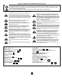
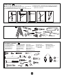
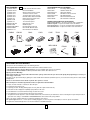
START BY READING THESE IMPORTANT SAFETY RULES
These safety alert symbols mean Caution – a personal safety or property damage instruction. Read these instructions carefully.
This garage door opener is designed and tested to offer reasonable safe service provided it is installed and operated in strict
accordance with the following safety rules.
Failure to comply with the following instructions may result in serious personal injury or property damage.
Caution: If your garage has no service entrance door, Model CM1702 Outside Quick Release must be installed. This accessory allows manual operation of the garage door from outside in case of power failure.
The force, as measured on the closing edge of the door,
should not exceed 400 N (40kg). If the closing force is
adjusted to more than 400 N, the Protector System must
be installed. Do not use the force adjustments to compensate for a binding or sticking garage door. Excessive force
will interfere with the proper operation of the Safety Reverse
System or damage the garage door.
Fasten the caution label adjacent to the lighted door control
button as a reminder of safe operating procedures.
Keep garage door balanced. Sticking or binding doors
must be repaired. Garage doors, door springs, cables, pulleys, brackets and their hardware are under extreme tension and can cause serious personal injury. Do not attempt
to loose, move or adjust them. Call for garage door service.
Do not wear rings, watches or loose clothing while
installing or servicing a garage door opener.
To avoid serious personal injury from entanglement,
remove all ropes connected to the garage door before
installing the door opener.
Disengage all existing garage door locks to avoid damage
to garage door.
Install the lighted door control button (or any additional push
buttons) in a location where the garage door is visible, but
out of the reach of children. Do not allow children to operate push button(s) or remote control(s). Serious personal
injury from a closing garage door may result from misuse of
the opener.
Activate opener only when the door is in full view, free of
obstructions and opener is properly adjusted. No one
should enter or leave the garage while the door is in
motion. Do not allow children to play near the door.
Use manual release only to disengage the trolley and, if possible, only when the door is closed. Do not use the red handle to pull the door open or closed.
Installation and wiring must be in compliance with your
local building and electrical codes. Connect the power
supply cord only to properly earthed mains.
Lightweight doors of fiberglass, aluminum or steel
must be substantially reinforced to avoid door damage.
(See page 4.) The best solution is to check with your
garage door manufacturer for an opener installation reinforcement kit.
The safety reverse system test is very important. Your
garage door MUST reverse on contact with a 50mm obstacle placed on the floor. Failure to properly adjust the opener
may result in serious personal injury from a closing garage
door. Repeat the test once a month and make any needed adjustments.
Disconnect electric power to the garage door opener
before making repairs or removing covers.
This product is provided with a power supply cord of special
design which, if damaged, must be replaced by a power
supply cord of the same type; such a power supply cord
may be obtained from your local Lift-Master distributor and
must be fitted by a specialist.
This unit should not be installed in a damp or wet
space.
Door must not extend over public byway during operation.
CONTENTS
ADJUSTMENT:
SAFETY RULES: Page 1
DOOR TYPES: Page 2 – Illustration
TOOLS REQUIRED: Illustration
Pages 13-14 – Illustrations 20
1
INSTALL THE PROTECTOR SYSTEM™: (Optional): Page 14 –
Illustration 23
OPERATION OF YOUR OPENER: Page 15
2
HARDWARE PROVIDED:
Page 2 – Illustration 3
CARE OF YOUR OPENER: Page 16
BEFORE YOU BEGIN: Page 3
PROBLEMS: Page 16 - 17
Planning:
MAINTENANCE OF YOUR OPENER: Page 16
Page 4 – Illustration 4
SPECIAL FEATURES OF THE 5580MT:
Page 14 – Illustration 24
ASSEMBLY: Page 5 – Illustrations 5 – 6
INSTALLATION:
Pages 6-11 – Illustrations
7
ACCESSORIES: Page 15 – Illustration
– 17
25
SPECIFICATIONS: Page 19
PROGRAMMING THE CODE:
Page 12 – Illustration
– 22
REPLACEMENT PARTS: Page 18 Illustrations
18 - 19
1
26
– 27
DOOR TYPES – 1
A. One-Piece Door with Horizontal Track Only
B. One-Piece Door with Horizontal and Vertical Track – Special door arm
(F, The Chamberlain Arm™) required. See your dealer.
C. Sectional Door with Curved Track – See 20 B – connect door arm.
A
B
TOOLS REQUIRED -
D. Double-wing door – Special door arm required. See your dealer.
E. Canopy door – Special door arm (F, The Chamberlain Arm™)
required. See your dealer.
E
D
C
2
1
2
10mm, 8mm,
4,5mm, 4mm
11mm, 13mm
HARDWARE PROVIDED – 3
Assembly Hardware:
(1) Washered Screws (2)
(2) Flat Washers (2)
(3) Hex Screws (2)
(4) Clevis Pin (1)
1
Installation Hardware:
(5) Carriage Bolts (2)
(6) Wood Screws (4)
(7) Clevis Pins (2)
(8) Hex Screws (4)
(9) Rope
(10) Handle
(11) Insulated Staples
(12) Anchors (2)
(13) Lock Washers (6)
(14) Nuts (6)
(15) Ring Fasteners (3)
Vibration Isolator:
(a) Vibration Isolator (2)
(b) Lock Washers (2)
(c) Nuts (2)
12
3
2
(16) Rail Grease
(17) 8mm Anchors (4)
(18) Sheet Metal
Screws (4)
a
13
4
16
7
b
14
5
8
17
9
6
18
10
NOTIC
E
11
15
2
c
BEFORE YOU BEGIN / PREPARING YOUR GARAGE DOOR:
1. Look at the wall or ceiling above the garage door. The header bracket must be securely fastened to structural supports.
2. Do you have a finished ceiling in your garage? If so, a support bracket and additional fastening hardware (not supplied) may be required.
3. Depending on your door's construction, you might need a special door arm. See your dealer.
4. Do you have an access door in addition to the garage door? If not, Model CM1702 Outside Quick Release Accessory is required.
5 Disable locks.
6 Remove any ropes connected to garage door.
7. Complete the following test to make sure your garage door is balanced and is not sticking or binding:
• Lift the door about halfway as shown. Release the door. If balanced, it should stay in place, supported entirely by its springs.
• Raise and lower the door to see if there is any binding or sticking.
If your door binds, sticks, or is out of balance, call a trained door systems technician.
Sectional Door
One-Piece Door
3
PLANNING - 4
Identify the type and height of your garage door. Survey your garage area to see if any of the conditions below apply to your installation. Additional materials may be required. You may find it helpful to refer back to this page and the accompanying illustrations as
you proceed with the installation of your opener.
FINISHED CEILING
SECTIONAL DOOR INSTALLATION
Support bracket &
fastening hardware
is required.
See page 12.
Horizontal and vertical reinforcement
is needed for lightweight garage doors
(fiberglass, steel, aluminum,
door with glass panels, etc.).
See page 19 for details.
Slack in chain tension
is normal when
garage door is closed.
Header Wall
Motor Unit
Extension Spring
Wallmounted
Door
Control
OR
———
Torsion Spring
Vertical Centerline
of Garage Door
Access Door
———
Safety
Reversing
Sensor
——
Gap between floor and bottom of door
must not exceed 1/4" (6 mm).
Safety Reversing Sensor
FINISHED CEILING
ONE-PIECE DOOR WITHOUT TRACK
Support bracket
& fastening
hardware is required.
See page 12.
Motor Unit
Slack in chain tension
is normal when
garage door is closed.
Header
Wall
Wallmounted
Door
Control
Access
Door
ONE-PIECE DOOR WITH TRACK
Safety
Reversing Sensor
Gap between floor and bottom of
door must not exceed 1/4" (6 mm).
Safety
Reversing Sensor
Slack in chain tension is normal when
garage door is closed.
Access
Door
4
Safety
Reversing Sensor
Safety
Gap between floor Reversing Sensor
and bottom of door
must not exceed 1/4" (6 mm).
ASSEMBLY SECTION
5
–
6
1
FASTEN T-RAIL & ATTACH CHAIN SPREADER – 5
3
Place packing material under the opener to protect the opener cover. For convenience,
place a support under the chain pulley bracket end of rail.
Remove Styrofoam from rail end and the (2) washered screws (4) from the top of the
opener. Align holes in back end of the T-rail with holes in opener (7).
2
4
Fasten the rail to the opener with the same washered screws and tighten securely.
Caution: Use only those screws!
Use of any other screws will cause serious damage to the door opener.
Attach the chain spreader (2) with hex screws (1) and flat washers (3).
3
1
7
TIGHTEN THE CHAIN -
6
Insert the threaded shaft (2) through the hole in the trolley (1). By hand, thread the spring trolley nut (3) on the threaded shaft until finger tight
against trolley. Insert a screwdriver tip (4) into one of the slots of the nut ring (7), and hold firmly. Using an open end wrench (5) at the square end
(6), slightly rotate the assembly clockwise until the nut ring (7) is released against the trolley, providing tension for the best operation of the opener.
1
7
5
2
3
4
6
ASSEMBLY OF YOUR OPENER IS NOW COMPLETE.
5
INSTALLATION SECTION
7
– 17
Wear protective goggles when working overhead to protect your
eyes from injury. Disengage all existing garage door locks to avoid
damage to the garage door. To avoid serious personal injury from
entanglement, remove all ropes connected to the garage door
before installing the opener.
Determine the Header Bracket Location -
Unfinished
Ceiling
2x4
Header Wall
7
OPTIONAL
CEILING
MOUNT
FOR
HEADER
BRACKET
Vertical Centerline
of Garage Door
Installation procedures vary according to garage door
types. Follow the instructions which apply to your door.
2x4
1. Close the door and mark the inside vertical
centerline of the garage door.
2. Extend the line onto the header wall above the
door.
You can fasten the header bracket within 4 feet
(1.22 m) of the left or right of the door center
only if a torsion spring or center bearing plate
is in the way; or you can attach it to the ceiling
(see page 9) when clearance is minimal. (It may
be mounted on the wall upside down if
necessary, to gain approximately 1/2" (1 cm).
If you need to install the header bracket on a 2x4
(on wall or ceiling), use lag screws (not provided)
to securely fasten the 2x4 to structural supports as
shown here and on page 9.
3. Open your door to the highest point of travel as
shown. Draw an intersecting horizontal line on the
header wall above the high point:
• 2" (5 cm) above the high point for sectional door
and one-piece door with track.
• 8" (20 cm) above the high point for one-piece
door without track.
This height will provide travel clearance for the top
edge of the door.
NOTE: If the total number of inches exceeds the
height available in your garage, use the maximum
height possible, or refer to page 9 for ceiling
installation.
Structural
Supports
Level
(optional)
Header Wall
3" (7.5 cm) Track
Track
Header Wall
3" (7.5 cm)
Highest Point
of Travel
Highest Point
of Travel
Door
Door
Sectional door with curved track
One-piece door with horizontal track
Header Wall
Header Wall
8" (20 cm)
8" (20 cm)
Door
Highest
Point
of Travel
Highest
Point
of Travel
Door
Jamb
Hardware
Pivot
One-piece door without track:
jamb hardware
6
One-piece door without track:
pivot hardware
INSTALL THE HEADER BRACKET –
8
A. Wall Mount: Center the bracket (2) on the vertical guideline (1) with the bottom edge of the bracket on the horizontal line (6) (with the arrow
pointing toward the ceiling). Mark either set of bracket holes (4 or 5). Do not use the holes designated for ceiling mount. Drill 4,5mm (3/16")
pilot holes and fasten the bracket with wood screws (3).
B. Ceiling Mount: Extend vertical guideline (1) onto the ceiling. Center the bracket (2) on the vertical mark no more than 150mm (6") from the wall.
Make sure the arrow is pointing toward the wall. Mark holes designated for ceiling mount only (4). Drill 4,5mm (3/16") pilot holes and fasten the
bracket with wood screws (3). For concrete ceiling mount, use concrete anchors (7) provided.
CEILING MOUNT ONLY
4
6
UP
1
ILING
CE
NT
MOU
LY
ON
3
UP
2
5
4
5cm
(2")
2
1
CEILING MOUNT ONLY
UP
150mm
(6")
UP
A
3
3
7
B
ATTACH T-RAIL TO HEADER BRACKET –
9
Position opener on garage floor below the header bracket. Use packing material to protect the cover.
Note: To enable the T-rail to clear sectional door springs, it may be necessary to lift opener onto a temporary support. The opener must either be
secured to a support or held firmly in place by another person. Raise T-rail until chain pulley and header brackets come together. Join with clevis
pin (1). Insert ring fastener (2) to secure.
2
1
1
2
7
1
POSITION THE OPENER – 10
Note: A 25mm (1") board (1) is convenient for setting an ideal door-to-T-rail
distance (unless headroom is not sufficient).
Raise the opener onto a stepladder. Open garage door. Place a 25mm (1")
board (1) laid flat on the top section of door near the centerline as shown.
Rest the T-rail on the board.
If the raised door hits the trolley, pull down on the trolley release arm to disconnect the inner and outer trolley sections. The trolley can remain disconnected until connecting door arm to trolley is completed.
INSTALL VIBRATION ISOLATORS - 11
Vibration Isolator
It’s use will help to eliminate vibration normally transmitted
Nut
thru the floor joists.
Washer
HANG THE OPENER – 12
The opener must be securely fastened to a structural support of the garage.
Three representative installations are shown. Yours may be
different. Hanging brackets (1) should be angled (Figure A) to
A
provide rigid support. On finished ceilings, (Figure B) attach a
sturdy metal bracket (not supplied) (4) to a structural support
before installing the opener. For concrete ceiling mount, (Figure
C), use concrete anchors (5) provided.
On each side of opener measure the distance from the opener to
1
the structural support (or ceiling).
Cut both pieces of the hanging bracket to required lengths.
Flatten one end of each bracket and bend or twist to fit the fas6
tening angles. Do not bend at the bracket holes. Drill 4,5mm
(3/16") pilot holes in the structural supports (or ceiling). Attach
flattened ends of brackets to supports with wood screws (2).
Lift opener and fasten to hanging brackets with screw, lock washer and nut (3). Check to make sure T-rail is centered over the
2
door. REMOVE 25mm (1") board. Operate door manually. If door
hits the rail, raise header bracket.
Grease the top and underside of rail surface on which the
trolley slides. A tube of grease is supplied.
B
2
2
4
1
3
3
2
1
3
6
C
5
2
3
1
2
3
5
6
8
ATTACH MANUAL RELEASE ROPE & HANDLE – 13
Thread one end of rope (1) through hole in top of red handle so "NOTICE" reads right side up as shown (3). Secure with an overhand knot (2).
Knot should be at least 25mm (1") from end of the rope to prevent slipping. Thread other end of rope through hole in release arm of the outer trolley (4). Adjust rope length so that handle is 1,8m (6 feet) above the floor. Secure with an overhand knot.
Note: If it is necessary to cut rope, heat seal cut end with a match or lighter to prevent fraying.
CONNECT ELECTRIC POWER
2
TO AVOID INSTALLATION DIFFICULTIES, DO NOT RUN
THE GARAGE DOOR OPENER UNTIL INSTRUCTED TO DO SO.
Connect the opener to a mains which is properly
EARTHED according to the wiring instruction tag attached to
power supply cord (and as specified by local code).
Connect the door opener only to an outlet controlled
by a double pole switch.
4
1
NOT
ICE
3
2
INSTALL WIRED DOOR CONTROLS (optional accessory) – 14
Locate wired door controls where the garage door is visible, away from door and door hardware, out of the reach of children and in a height
of at least 1.5m.
Serious personal injury from a moving garage door may result from misuse of opener. Do not allow children to operate the wired door controls or remote control transmitters.
Fasten the caution label on the wall near wired door controls as a reminder of safe operating procedures.
There are 2 screw terminals (1) on the back of the wired door controls (2). Strip about 6mm (1/4") of insulation from bell wire (4). Separate wires
enough to connect the white/red wire to terminal screw 1 and the white wire to terminal screw 2.
Fasten wired door controls to an inside garage wall with sheet metal screws (3) provided. Drill 4mm (5/32") holes and use anchors (6) if installing into
drywall. A convenient place is beside the service door and out of reach of children.
Run the bell wire up the wall and across the ceiling to the garage door opener. Use insulated staples (5) to secure wire. The receiver terminal screws
(7) are located on the back panel of the opener. Connect the bell wire to the terminal screws as follows: white/red to 1 and white to 2.
1
4
6mm
WHT
-2
RED
-1
7
2
3
LOCK
Push Bar Cover
LIGHT
5
4
3
6
OPERATION OF THE WIRED DOOR CONTROLS
Press to open or close the door. Press again to reverse the door
during the closing cycle or to stop the door during opening cycle.
9
8
INSTALL THE LIGHT AND LENS – 15
Install a 40 watt maximum light bulb (1) in the socket as shown. The light will turn on and remain lit for 4-1/2 minutes when power is connected.
After 4-1/2 minutes it will turn off.
Replace burned out bulbs with rough service light bulbs.
Apply slight pressure on sides of the lens (2) and slide tabs (3) into slots (4) in the end panel. Reverse the procedure to remove the lens.
1
40W
E27
2
3
FASTEN DOOR BRACKET – 16
If yours is a canopy or dual-track style garage door, a door arm conversion kit is required. Follow the installation instructions included with the replacement door arm. Exercise care in removing and assembling arm
conversion kit. Keep fingers away from the sliding parts.
NOTE: Horizontal and vertical reinforcement is needed
for lightweight garage doors.
Sectional and One-Piece Door Installation Procedure:
Door bracket (1) has left and right side fastening holes.
Assemble and install the bracket and plate (2) if your
installation requires top and bottom fastening holes.
1. Center bracket (with or without plate, as required) at
the top of inside face of door as shown. Mark holes.
A. 0-100mm
B. 150-250mm
2. A. Wooden doors
Drill 8mm holes (5/16") and fasten the door bracket
with nut, lock washer, and carriage bolt (3).
B. Sheet metal doors
Fasten with sheet metal screws (4).
C. One-piece door optional
3
A
B
Fasten with sheet metal screws (4).
1
3
4
1
C
1
2
2
3
4
10
4
ASSEMBLE DOOR ARM AND SET LIMITS – 17
NOTE: For one-piece doors, do not connect door arm to trolley before adjusting limits. Failure to follow instructions may result in damage to door. See below.
A. SECTIONAL DOOR INSTALLATION:
Connect according to Figure B, then proceed to
Step 18.
B. ONE-PIECE DOOR INSTALLATION:
Connect straight door arm (1) and curved door arm sections (2) to obtain the longest possible length with hardware (3, 4 & 5). With door closed,
connect straight door arm section to door bracket with a clevis pin (6). Secure with a ring fastener (7).
Before connecting door arm to trolley, adjust travel limits. Limit adjustment screws are located on left side panel.
Open Door Adjustment: Decrease up limit. Turn up limit adjustment screw counterclockwise 5-1/2 turns.
Press door control button. Trolley will travel to full open position (8). Manually raise door to open position (parallel to floor) and lift
door arm (9) to trolley. The arm should touch trolley just in back of door arm connector hole (10) as shown in solid line drawing. Increase up limit if
necessary. One full turn equals 5cm (2") of door travel.
Closed Door Adjustment: Decrease down limit. Turn down limit adjustment screw clockwise 5 complete turns.
Press door control button. Trolley will travel to full
closed position (11). Manually close door and lift door A
4
7
5
arm (12) to trolley. The arm should touch trolley just
ahead of door arm connector hole (13) as shown in
dotted line drawing. Decrease down limit if neces6
4
3
sary. One full turn equals 5cm (2") of door travel.
Connect Door Arm to Trolley: With door closed,
5
connect curved arm to trolley with remaining clevis
pin. Secure with ring fastener. Note: Lift door
slightly to make connection if necessary.
3
BB
Run opener through a complete travel cycle. If door
7
4 5
has a slight "backward" slant in full open position,
1
decrease up limits until door is parallel to floor.
6
3
11
2
8
10
13
12
11
9
PROGRAM YOUR OPENER & REMOTE – 18
Activate the opener only when door is in full view, free of obstruction and properly adjusted. No one should enter or leave garage while
door is in motion. Do not allow children to operate push button(s) or remote(s). Do not allow children to play near the door.
Your garage door opener receiver and remote control transmitter are set to a matching code. If you purchase additional remote controls, the garage
door opener must be programmed to accept the new remote code. Program the Receiver to Match Additional Remote Control Codes:
Using the “LEARN” Button
1. Press and release the “learn” button on the motor unit. The learn indicator light will glow steadily for 30 seconds (1).
2. Within 30 seconds, press and hold the button on the hand-held remote that you wish to operate your garage door (2).
3. Release the button when the motor unit light blinks. It has learned the code. If light bulb is not installed, two clicks will be heard (3).
Using the Motion Detecting Control Panel (optional accessory):
1. Press and hold the button on the hand-held remote that you wish to operate your garage door (4).
2. While holding the remote button, press and hold the LIGHT button on the Motion Detecting Control Panel (5).
3. Continue holding both buttons while you press the push bar on the Motion Detecting Control Panel (all three buttons are held) (6).
4. Release buttons when the opener light blinks. It has learned the code. If the light bulb is not installed, two clicks will be heard (7).
To Erase all Remote Control Codes
To deactivate any unwanted remote, first erase all codes:
Press and hold the “learn” button on motor unit until the learn indicator light goes out (approximately 6 seconds). All previous codes are now erased.
Reprogram each remote or keyless entry you wish to use.
1
2
3
4
7
6
5
LIGHT
LOCK
LOCK
LIGHT
PROGRAM YOUR RADIO WALL CONTROL -
19
Activate the opener only when door is in full view, free of obstruction and properly adjusted. No one should enter or leave garage while
door is in motion. Do not allow children to operate push button(s) or remote(s). Do not allow children to play near the door. Locate minimum 1.5m above the floor.
Remote control slide-on wall mount bracket:
-Attach to the wall with 2x ø 3.5 max.flat head screws
(not provided )
-Slide remote control onto wall mount bracket
NOTE: Tightening the wall mount screws will reduce clearance between bracket and wall.
Program the Receiver to Match Additional Remote Control Code
Using the orange “LEARN” Button:
1. Press and release the orange “learn” button on opener.
The learn indicator light will glow steadily for 30 seconds.
2. Within 30 seconds, press and hold the button on the radio
wall control that you wish to operate your garage door.
3. Release the button when the opener light blinks.
It has learned the code. If the light bulb is not installed, two clicks will be heard.
12
ADJUSTMENT SECTION 20
– 22
LIMIT ADJUSTMENT – 20
Run the opener through a complete travel cycle. Limit adjustments are not necessary when the door opens and closes completely and doesn't
reverse unintentionally in the fully closed position.
Situations requiring limit adjustment are listed below. Run the opener through a complete travel cycle after each adjustment.
Note: Repeated operation of the opener during adjustment procedures may cause motor to overheat and shut off. Allow a 15 minute cooling period after 5 continuous operations of the opener.
Read the following carefully before proceeding to Force Adjustment.
Use a screwdriver to make limit adjustments.
If Door Doesn't Open Completely but Opens at Least 1,5m (5 feet):
Increase up travel. Turn the up limit adjustment screw (1) clockwise.
One turn equals 5cm (2") of travel.
If door reverses before reaching the desired UP position:
Adjust up (open) force. See Force Adjustment.
If Door Doesn't Close Completely: If door arm is at maximum length, increase down travel.
Turn down limit adjustment screw (2) counterclockwise. One turn equals 5cm (2") of travel. If
the door still will not close completely, the header bracket is positioned too high.
1
If Opener Reverses in Fully Closed Position: Decrease down travel. Turn down limit
adjustment screw (2) clockwise. One turn equals 5cm (2") of travel.
If Door Reverses when Closing and there is no Interference to Travel Cycle: Test door
for binding. Pull manual release handle. Manually open and close door. If door is binding, call
a door serviceman. If door is not binding or unbalanced, adjust down (close) force.
2
3
1
(2x)
FORCE ADJUSTMENT – 21
The force, as measured on the closing edge of the door, should not exceed 400N (40kg). If the closing force is measured to more than 400N, the Protector System must be installed See step 25.
The force setting button is located on the back panel of the motor unit. The force setting regulates
the amount of power required to open and close the door. If the forces are too light, door travel may
be interrupted by nuisance reversals.
Locate the button (1) on the back panel of motor unit. Push the button twice to enter into Force
Setting Mode. The LED (Indicator Light) will flash. Push the wall control or the programmed remote
control that was shipped with your opener. The door will travel to either the OPEN or CLOSE position. Push the button again, the door will travel to the opposite position. Push the button again if the
LED is stilling blinking.
The door must travel through a complete cycle UP and DOWN in order for the force to be set properly. If the unit reverses before it reaches the Open or Close Limit repeat the process. The LED (indicator light) will stop flashing when the force has been learned.
Note: If unable to set limits return to section 20.
1
1
(2x)
13
TEST THE SAFETY REVERSE SYSTEM – 22
The safety reverse system test is important. Garage door must reverse on contact with a 40mm obstacle laid flat on the floor. Failure to
properly adjust opener may result in serious personal injury from a closing garage door. Repeat test once a month and adjust as needed.
Procedure: Place a 40mm obstacle (1) laid flat on the floor under the garage door. Operate
the door in the down direction. The door must reverse on the obstruction. If the door stops
on the obstruction, it is not traveling far enough in the down direction. Increase the down
limit by turning down limit adjustment screw counterclockwise 1/4 turn. Repeat test.
When the door reverses on the 40mm obstacle, remove the obstruction and run the opener
through a complete travel cycle. Door must not reverse in closed position. If it does, adjust
Limits and Force and repeat safety reverse test.
1
INSTALL THE PROTECTOR SYSTEM™ – 23
(See accessories)
Install this accessory for all installations on Canopy doors, 1 piece dual track
doors, doors over 2.5m and when the closing force as measured on the bottom of the door is over 400N (40kg).
After opener has been installed and adjusted, The Protector System™ accessory
can be installed. Instructions are included with this accessory.
The Protector System™ provides an additional measure of safety against a
small child being caught under a garage door.
It uses an invisible beam which, when broken by an obstruction, causes a closing
door to open and prevents an open door from closing and is strongly recommend1 2 3 4
ed for homeowners with young children.
Note: The opener will automatically detect the protector system when it is installed. The opener will not close unless the sensors are aligned.
SPECIAL FEATURES OF THE 5580MT – 24
A.
Door within a door connection
B.
Disconnect opener from power!
Remove cover. Locate auxiliary terminal block (TB1) on the control board. Remove jumper from terminal leads 1 and 2 (not shown). Replace
with contact switch leads as shown.
Flashing light connection
C.
The flashing light can be installed anywhere. Connect light leads to terminals 3 and 4 on the terminal block.
Coaxial antenna adapter
A coaxial antenna connection can be used if the transmitter range is too
short. Cut off the existing antenna. Use standard coax cable and connector. Strip off end of insulation to “X” dimension.
433 MHz: X = 250mm. Reposition antenna.
B
A
TB1
C
TB1
X = 433 MHz = 250mm
14
ACCESSORIES – 25
(1) Model CM842
(2) Model CM128
(3) Model C940
(4) Model C943
(5) Model C945
(6) Model 75LM
(7) Model C98
(8)Model C840
(9) Model C77
(10)Model CM1702
(11)Model 760E
(12)Model MDL100LM
(13)Model EQL01
(14)Model 9-13-1
CM842
ACCESSORIES NOT ILLUSTRATED
Double-Function Remote Control
Remote Wall Button
Single-Function Remote Control
3-Function Remote Control
3-Function Mini Remote Control
Illuminated Door Bell Push Button
Motion Detecting Control Panel
Keyless Entry System
The Protector System
Quick Release Lock
Outside Keylock
Mechanical Door Latch Kit
Door Handle Quick Release
Door Reinforcement Bracket
C940
CM128
1
2
CM475
89LM
SDA-1LM
CSTAR
041A2743X
86LM
23024E
Evercharge Battery Sytem
Vibration Isolator Kit
Wing Door Adaptor
Star 250-433 Access Control
Star Watertight Box
Star Antenna Extension Kit
Star Transformer 230V/24V
WIRING INSTRUCTIONS FOR ACCESSORIES
Keyless Entry System – To opener terminals: Red-1 and White-2
Outside Keylock – To opener terminals: Red-1 and White-2
Protector System™ – To opener terminals: White-2 and Black-3
Door Control Panel – To opener terminals: Red-1 and White-2
C943
C840
C98
75LM
C945
6
3
CM1702
C77
Model
Model
Model
Model
Model
Model
Model
4
10
7
LIGHT
MDL100LM
760E
9
LOCK
5
EQL01
8
9-13-1
11
12
13
14
OPERATION OF YOUR OPENER
Your opener can be activated by any of the following devices:
• The Lighted Door Control Button. Hold the button down until door starts to move.
• The Outside Keylock or Keyless Entry System (if you have installed either of these accessories).
• The Remote Control Transmitter. Hold the push button down until the door starts to move.
Opening the Door Manually:
Door should be fully closed if possible. Weak or broken springs could allow an open door to fall rapidly. Property damage or serious personal injury could result.
The door can be opened manually by pulling the release handle down and back (toward the opener). To reconnect the door, pull the release handle
straight down.
Do not use the manual release handle to pull the door opener or closed.
When the Opener is Activated by Remote Control or Lighted Door Control Button:
1. If open, the door will close. If closed, the door will open.
2. If closing, the door will reverse.
3. If opening, the door will stop (allowing space for entry and exit of pets and for fresh air).
4. If the door has been stopped in a partially open position, it will close.
5. If an obstruction is encountered while closing, the door will reverse.
6. If an obstruction is encountered while opening, the door will stop.
7. The optional Protector System™ uses an invisible beam which, when broken by an obstruction, causes a closing door to open and prevents an
open door from closing. It is STRONGLY RECOMMENDED for homeowners with young children.
Allow a 15 minute cooling period after 5 continuous operations of the opener.
The opener light will turn on: 1. when opener is initially plugged in; 2. when the power is interrupted; 3. when the opener is activated.
The light turns off automatically after 4-1/2 minutes. Bulb size is 40 Watts maximum.
15
CARE OF YOUR OPENER
When properly installed, opener will provide high performance with a minimum of maintenance. The opener does not require additional lubrication.
Limit and Force Adjustments: These adjustments must be checked and properly set when opener is installed. Only a screwdriver is
required. Weather conditions may cause some minor changes in the door operation, requiring some re-adjustments, particularly during the first year
of operation.
Refer to the limit and force adjustments on page 13. Follow the instructions carefully and repeat the safety reverse test after any adjustment.
Remote Control Transmitter: The portable remote control may be secured to a car sun visor with the clip provided. Additional remotes can be
purchased at any time for use in all vehicles using garage. Refer to Accessories. Any new remotes must be set to the same code as the original
remote.
Remote Control Battery: The lithium batteries should produce power for up to 5 years. When the light becomes dim or does not come on, replace
the battery. If transmission range lessens, check the battery test light.
To Change Battery: To replace batteries, use the visor clip or screwdriver blade to pry open the case. Insert batteries positive side up. To replace
cover, snap shut along both sides. Do not dispose of the old battery with household waste. Take batteries to a proper disposal center.
MAINTENANCE OF YOUR OPENER
Once a Month:
• Repeat safety reverse test. Make any necessary adjustments.
• Manually operate door. If it is unbalanced or binding, call for professional garage door service.
• Check to be sure door opens and closes fully. Adjust Limits and/or Force if necessary.
Once a Year:
Oil door rollers, bearings and hinges. The opener does not require additional lubrication. Do not grease the door tracks.
HAVING A PROBLEM?
1. Opener doesn't operate from either door control or remote:
• Does the opener have electric power? Plug lamp into outlet. If it doesn't light, check the fuse box or the circuit breaker. (Some outlets are controlled
by a wall switch.)
• Have you disengaged all door locks? Review installation instruction warnings on page 1.
• Is there a build-up of ice or snow under door? The door may be frozen to ground. Remove any obstruction.
• The garage door spring may be broken. Have it replaced.
• Repeated operation may have tripped the overload protector in the motor. Wait 15 minutes. Try again.
2. Opener operates from remote but not from door control:
• Is door control button lit? If not, remove the bell wire from the opener terminals. Short the red and white terminals by touching both terminals at the
same time with a piece of wire. If the opener runs, check for a faulty wire connection at the door control, a short under the staples, or a broken wire.
• Are wiring connections correct? Review page 10.
3. Door operates from door control but not from remote:
• Check battery. Replace battery if necessary.
• Is the light at the wall control flashing? Press button with key-symbol to unlock the opener against remote controls.
• Is the receiver LED flashing at the back-side of the opener when the transmitter is pressed? The opener receiver must re-learn the remote control
code. Follow the instructions on page 4.
• If you purchased a new remote control then check at carton of remote control for compatibility or call the Service Hotline.
4. Remote has short range:
• Is battery installed? If needed, change the battery.
• Change the location of the remote control on the car.
• A metal garage door, foil-backed insulation or metal siding will reduce the transmission range.
• Use outside coaxial antenna adapter to move antenna.
5. Door reverses for no apparent reason and opener light doesn't blink:
• Is something obstructing the door? Pull manual release handle. Operate door manually. If it is unbalanced or binding, call for professional garage
door service.
• Clear any ice or snow from garage floor area where garage door closes.
• Review Force Settings. Open and close the door in learn mode for several (3-5) consecutive cycles to allow the operator to adjust to inconsistent
doors.
• If door reverses in FULLY CLOSED position, re-learn travel limits.
Repeat safety reverse test after adjustment is complete.
The need for occasional adjustment of the force and limit settings is normal. Weather conditions in particular can affect door travel.
16
6. Door reverses for no apparent reason and opener light blinks for 5 seconds after reversing:
Check The Protector System™ (if you have installed this accessory). If the light is blinking, correct alignment.
Note: Continuously holding down the door control button will allow the door to close if the protector system is not properly aligned. The transmitter will
not close the door. The opener lights will blink.
7. Opener noise is disturbing in living quarters of home:
If operational noise is a problem because of proximity of the opener to the living quarters, Vibration Isolator Kit 41A3263 can be installed. This kit was
designed to reduce the "sounding board effect" and is easy to install.
8. The garage door opens and closes by itself:
• Delete all remote controls and reprogram.
• Make sure remote push button is not stuck "on".
• Disconnect all push buttons or key switches attached and wait one day.
9. Door stops but doesn't close completely:
Review Limit Adjustment section.
Repeat safety reverse test after any adjustment of door arm length, close force or down limit.
10. Door opens but won't close:
• Check The Protector System™ (if you have installed this accessory). If the light is blinking, correct alignment.
• If opener light does not blink and it is a new installation, check the down force.
Repeat the safety reverse test after the adjustment is complete.
11. Opener light does not turn on:
Replace light bulb (40 Watts maximum). Replace burned out bulbs with rough service light bulbs.
12. Opener light does not turn off:
There may be a defective earth at the ceiling or wall receptacle. The unit must be earthed.
13. Opener strains or reversed during opening:
Door may be unbalanced or springs are broken. Close door and use manual release rope and handle to disconnect trolley. Open and close door manually. A properly balanced door will stay in any point of travel while being supported entirely by its springs. If it does not, call for professional garage
door service to correct the problem. Do not change force settings.
14. Opener motor hums briefly, then won't work:
• Garage door springs are broken. SEE ABOVE.
• If problem occurs on first operation of opener, door is locked. Disable door lock. If chain was removed and reinstalled, the motor may be out of
phase. Remove chain; cycle motor to down position. Observe drive sprocket. When it turns in clockwise direction and stops in down position, reinstall chain.
Repeat safety reverse test after adjustment is complete.
15. Opener won't activate due to power failure:
• Pull manual release rope and handle down and back to disconnect trolley. Door can be opened and closed manually. When the power is restored,
pull the manual release handle straight down. The next time the opener is activated, the trolley will reconnect.
• The Outside Quick Release accessory (if fitted) disconnects the trolley from outside the garage in case of power failure.
17
REPLACEMENT PARTS
26
041A4208
Chain
Styrofoam
041A3263
One-Piece
Rail
178B34
Trolley
Chain
Pulley Bracket
1706E (1,7m)
1707E (2,3m)
1708E (2,5m)
1710E (3m)
178B69
41D3484-1 (1,7m)
41D3484-2 (2,3m)
41D3484-3 (2,4m)
41D3484-4 (3m)
CE
ILI
NG
MO
UN
T ON
LY
UP
41B4103-1
178B35B
41A4353-1
E
AS
RE
IL G A4
RA
. 83
NO
83A4
12B374
217A238
NOT
ICE
4A1008
12B380
1A5414
41A2828
41A5833
REPLACEMENT PARTS
27
175B174
41B4375
41A5813
108D68-1
41A5831
41A5809
30B415
81C253
41A5640
18
41C4398A
SPECIFICATIONS
Max. Pull Force ..............800N
Rated Power...................400 W
GARAGE DOOR OPENER WARRANTY
Motor
Type ................................Permanent split capacitor
Speed .............................1500 rpm
Volts ................................230-240 Volts AC-50Hz Only
Chamberlain GmbH warrants to the first retail purchaser of this
product that the product shall be free from any defect in materials
and/or workmanship for a period of 24 full months (2 years) from
the date of purchase. Upon receipt of the product, the first retail
purchaser is under obligation to check the product for any visible
defects.
Conditions: The warranty is strictly limited to the reparation or
replacement of the parts of this product which are found to be
defective and does not cover the costs or risks of transportation
of the defective parts or product.
This warranty does not cover non-defect damage caused by
unreasonable use (including use not in complete accordance
with Chamberlain’s instructions for installation, operation and
care; failure to provide necessary maintenance and adjustment;
or any adaptations of or alterations to the products), labor
charges for dismantling or reinstalling of a repaired or replaced
unit or replacement batteries.
A product under warranty which is determined to be defective in
materials and/or workmanship will be repaired or replaced (at
Chamberlain's option) at no cost to the owner for the repair
and/or replacement parts and/or product. Defective parts will be
repaired or replaced with new or factory rebuilt parts at
Chamberlain's option.
If, during the warranty period, the product appears as though it
may be defective, contact your original place of purchase.
This warranty does not affect the purchaser’s statutory rights
under applicable national legislation in force nor the purchaser’s
rights against the retailer arising from their sales/purchase contract. In the absence of applicable national or EU legislation, this
warranty will be the purchaser’s sole and exclusive remedy, and
neither Chamberlain nor its affiliates or distributors shall be liable
for any incidental or consequential damages for any express or
implied warranty relating to this product.
No representative or person is authorized to assume for
Chamberlain any other liability in connection with the sale of this
product.
Drive Mechanism
Gears ..............................16:1 worm gear reduction
Drive ...............................Chain with two-piece trolley on
steel rail.
Length of Travel..............Adjustable to 2,3m (7-1/2 feet)
Travel Rate .....................96-135mm (3,8"-5,3") per second
Lamp...............................On when door starts, off 2-1/2 minutes
after stop.
Door Linkage ..................Adjustable door arm. Pull cord trolley
release.
Safety
Personal .........................Push button stop in UP and DOWN direction. Automatic force reversal in UP and
DOWN direction.
Electronic ........................Automatic force adjustments.
Electrical .........................Motor overload protector and low voltage
push button wiring.
Limit Device ....................Circuit actuated by limit nut.
Limit Adjustment .............Screwdriver adjustment on side panel.
Start Circuit .....................Low voltage push button circuit.
Dimensions
Length (Overall)..............3,1m (122-1/2")
Headroom Required .......30mm
Hanging Weight ..............14,5 kg (32 lb)
Receiver
Memory Registers ..........8
Keypad Code Memory....1
SPECIAL NOTE: Chamberlain strongly recommends that the protector system be installed on all garage door openers.
114A3374
19
© 2007, Chamberlain GmbH
All rights reserved