1
OPERATING & MAINTENANCE MANUAL
EXSM 230 S and 350 S
438 9030-16/01
02.32
WARNING: ALL OPERATING AND MAINTENANCE PROCEDURES SHOWN ON THE NEXT
PAGE OF THIS MANUAL MUST BE FOLLOWED DAILY FOR PROPER OPERATION OF
YOUR WASCOMAT MACHINE.
PLEASE ENTER THE FOLLOWING INFORMATION AS IT APPEARS ON THE MACHINE(S)
DATA PLATE(S).
MACHINE TYPE OR MODEL
MACHINE SERIAL NUMBER(S)
ELECTRICAL CHARACTERISTICS: ________ VOLTS, _______ PHASE, _______ HZ.
MAKE CERTAIN TO KEEP THIS MANUAL IN A SECURE PLACE FOR FUTURE
REFERENCE.
II
NOTICE TO: OWNERS, OPERATORS AND DEALERS OF WASCOMAT MACHINES
IMPROPER INSTALLATION AND INADEQUATE MAINTENANCE, POOR HOUSEKEEPING AND WILLFUL
NEGLECT OR BYPASSING OF SAFETY DEVICES MAY RESULT IN SERIOUS ACCIDENTS OR INJURY.
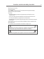
TO ASSURE THE SAFETY OF CUSTOMERS AND/OR OPERATORS OF YOUR MACHINE, THE FOLLOWING MAINTENANCE CHECKS MUST BE PERFORMED ON A DAILY BASIS.
1.
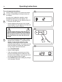
Prior to operation of the machine, check to make certain that all operating instructions and
warning signs are affixed to the machine and legible. (See the following page of this manual
for description and location of the signs.) Missing or illegible ones must be replaced immediately. Be sure you have spare signs and labels available at all times. These can be obtained from your dealer or Wascomat.
2.
Check the door safety interlock, as follows:
(a)
OPEN THE DOOR of the machine and attempt to start in the normal manner:
For CLARUS microprocessor models, choose a program and press the START
button.
THE MACHINE(S) SHOULD NOT START !
(b)
CLOSE THE DOOR to start machine operation and, while it is operating, attempt to
open the door without exerting extreme force on the door handle. The door should
remain locked!
If the machine can start with the door open, or can continue to operate with the door
unlocked, the door interlock is no longer operating properly. The machine must be
placed out of order and the interlock immediately repaired or replaced. (See the door
interlock section of the manual.)
3.
DO NOT UNDER ANY CIRCUMSTANCES ATTEMPT TO BYPASS OR REWIRE ANY OF
THE MACHINE SAFETY DEVICES, AS THIS CAN RESULT IN SERIOUS ACCIDENTS.
4.
Be sure to keep the machine(s) in proper working order: Follow all maintenance and
safety procedures. Further information regarding machine safety, service and parts can be
obtained from your dealer or from Wascomat through its Teletech Service Line - 516/3710700.
All requests for assistance must include the model, serial number and electrical characteristics as
they appear on the machine identification plate. Insert this information in the space provided on the
previous page of this manual.
5.
WARNING: DO NOT OPERATE MACHINE(S) WITH SAFETY DEVICES BYPASSED, REWIRED OR
INOPERATIVE! DO NOT OPEN MACHINE DOOR UNTIL DRUM HAS STOPPED ROTATING!
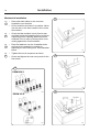
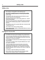
SAFETY AND WARNINGS SIGNS
Replace If Missing Or Illegible
One or more of these signs must be affixed on each machine as indicated, when not included as part of the front instruction panel.
LOCATED ON THE OPERATING INSTRUCTION SIGN OF THE MACHINE:
CAUTION
PRECAUCION
1. Do not open washer door until cycle is completed and wash
cylinder has stopped rotating.
1. No abra la puerta de la máquina lavadora sino hasta que la
máquina haya terminado su ciclo, la luz operativa esté apaga
da y el cilindro de lavado haya completamento terminado de
girar.
2. Do not tamper with the door safety switch or door lock.
3. Do not attempt to open door or place hands into washer to
remove or add clothes during operation. This can cause
serious injury.
2. No interferia o manipule el switch o la cerradura de la puerta.
MACHINE SHOULD NOT BE USED BY CHILDREN
LAS MÁQUINAS NO DEBEN SER USADAS POR NIÑOS
3. No trate de abrir la puerta o meta las manos dentro de la
máquina para meter o sacar ropa mientras la máquina está
en operación, pues puede resultar seriamento herido.
LOCATED AT THE REAR OF THE MACHINE:
INSTALLATION AND
MAINTENANCE WARNINGS – AVERTISSEMENT
1. This machine MUST be securely bolted according to the installation instructions, to
reduce the risk of fire and to prevent serious injury, or damage to the machine.
Pour reduire les risques d'incendie, fixer cet appareil sur un plancher beton sans
revetement.
2. If installed on a floor of combustible material, the floor area below this machine must
be covered by a metal sheet extending to the outer edges of the machine.
3. This machine MUST be connected to a dedicated electrical circuit to which no other
lightning unit or general purpose receptacle is connected. Use copper conductor only.
Utiliser seulement des conducteurs en cuivre.
4. This machine MUST be serviced and operated in compliance with manufacturer's
instructions. CHECK DOOR LOCKS EVERY DAY FOR PROPER OPERATION TO PREVENT INJURY OR DAMAGE. IF THE DOOR LOCK FAILS TO OPERATE PROPERLY,
PLACE THE MACHINE OUT OF ORDER UNTIL THE PROBLEM IS CORRECTED.
5. Disconnect power prior to servicing of machine.
Deconnecter cet appareil del'alimentation avant de proceder a l'entretien.
6. To remove top panel, first remove eventual screws at the rear. When remounting the
top, reinstall them. To remove the top panel on models on which it is secured by one or
two keylocks, use the keys originally shipped in the drum package. Be certain to relock
after remounting the top panel.
MANUFACTURED BY WASCATOR
DISTRIBUTED BY WASCOMAT, INWOOD, NEW YORK, USA
471 766202-04
LOCATED ON THE DOOR:
If you need to order more safety or warning
signs, call Wascomat's parts department at
516-371-2000, or call your local dealer.
471 467148-01
EXSM 230 S and 350 S
Contents
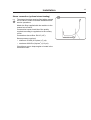
Introduction .................................................................................................. 7
Technical data .............................................................................................. 8
Installation .................................................................................................. 11
Function control and safety checklist ......................................................... 22
Safety rules ................................................................................................ 24
Mechanical and electrical design ............................................................... 25
Procedure for use ....................................................................................... 51
Fault-finding ............................................................................................. 102
Maintenance ............................................................................................. 136
Trouble-shooting ...................................................................................... 138
Encl. Hospitality wash programs
The manufacturer reservs the right to make changes to design and
material specification without notice.
Safety instructions
• The machine is designed for water washing only.
• The machine must not be used by children.
• All installation operations are to be carried out by qualified,
licensed personnel.
• The door interlock must be checked daily for proper operation
and must not be bypased.
• All seepage in the system, due to faulty gaskets etc., must be
repaired immediately.
• All service personnel must be fully familiar with the operating
manual before attempting any repair or maintenance of the
machine.
• The machine must not be sprayed with water, otherwise short
circuiting may occur.
• Volatile or inflammable fluids are not to be used in the
machine.
5
Introduction
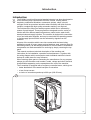
7
Introduction
The EXSM-S model solid mounted washer/extractor has been developed to
cover the heavy duty requirements of hotels, motels, nursing homes,
hospitals, professional laundries, restaurants, airlines, ships, schools,
colleges and all on-premises laundries where flexibility and quick formula
variation, coupled with high quality automatic washing, are required.
The Selecta offers 28 pre-set wash programs which can be selected by
means of push buttons. These programs are designed to suit a variety of
fabrics and offer different water temperatures, water levels, wash levels,
wash periods and supply injection. The machine is designed for connection
to hot and cold water supplies, and may be used with free-standing powder
or liquid supply injectors which can be activated by signals from the
machine.
All parts of the machine which come into contact with the items being
washed are made of heavy gauge surgical stainless steel, ensuring long life
and lasting beauty, as well as full protection for no-iron fabrics. All electrical
components are made accessible for servicing by simply removing the top
panel.
This manual contains a technical description of the machine and
instructions for its installation, operation and maintenance. Together with
the wiring diagram which accompanies each individual machine it should
be kept in a safe place for easy reference.
When ordering spare parts or contacting the manufacturer for any purpose
always give the machine serial number, model, voltage and other electrical
characteristics appearing on the nameplate at the rear of the machine.
The S-machine is equipped with a frequency controlled motor, which gives:
• better distribution of the wash load prior to extraction.
• a low of start current.
• a choice of extraction speeds up to 690 rpm (220 G-force).
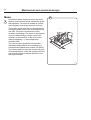
Fig.
1
1
4941
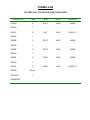
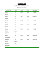
Technical data
8
EXSM 230 S
Dry load capacity
up to
Overall dimensions
Width
Depth
Height
Net weight
Max. floor load at extraction
Frequency (dynamic force)
65 lbs
935 mm
1100 mm
1430 mm
365 kg
36 7/8''
43 3/8''
56 1/4''
805 lbs
5,0±11.5 kN
12 Hz
1200±2760 lbs.force
Crated Dimensions
Volume
Weight
1.85 m3
361 kg
65 cu.ft
795 lbs
Inner drum
Diameter
Depth
Volume
830 mm
425 mm
230 litre
32 11/16''
16 3/4''
8.12 cu.ft
Speed of rotation
Wash
Distribution
Extraction, max
41 rpm
72 rpm
690 rpm
G-factor
During wash
During extrac., max
0.8
220
Motor speed
During wash
During distrib.
During extrac., max
450 rpm
770 rpm
7390 rpm
Rated power
Motor, wash
Motor, distrib.
Motor, extrac.
0.85 kW
0.25 kW
1.0 kW
Voltage requirements
Full load amps
Overcurrent protection
208-240 V 1-Phase 60 Hz
15A
20A
Water connections
Recommended water pressure 2-6 kp/cm2
25-85 psi
Hose connection, water
DN 20
3/4''
Hose connection, steam
DN 15
1/2''
Hose connection, drain
75 mm
3''
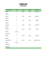
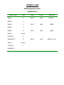
Technical data
9
EXSM 350 S
Dry load capacity
up to
Overall dimensions
Width
Depth
Height
Net weight
Max. floor load at extraction
Frequency (dynamic force)
80 lbs
1085 mm
1325 mm
1540 mm
545 kg
42 3/4''
52 1/8''
60 5/8''
1200 lbs
6.5±14 kN
10,8 Hz
1560±3147 lbs.force
Crated Dimensions
Volume
Weight
2.4 m3
545 kg
85 cu.ft
1199 lbs
Inner drum
Diameter
Depth
Volume
920 mm
520 mm
350 litre
36 1/4''
20 1/2''
12.6 cu.ft
Speed of rotation
Wash
Distribution
Extraction, max
40 rpm
70 rpm
650 rpm
G-factor
During wash
During extrac., max
0.8
220
Motor speed
During wash
During distrib.
During extrac., max
500 rpm
870 rpm
8200 rpm
Rated power
Motor, wash
Motor, distrib.
Motor, extrac.
1.2 kW
0.3 kW
1.5 kW
Voltage requirements
Full load amps
Overcurrent protection
208-240 V 1-Phase 60 Hz
15A
20A
Water connections
Recommended water pressure 2-6 kp/cm2
25-85 psi
Hose connection, water
DN 20
3/4''
Hose connection, steam
DN 15
1/2''
Hose connection, drain
75 mm
3''
Technical data
10
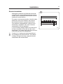
Outline and dimensions
5
N
P
4
T
B
M
A
6
7
1
H
C
L
G
O
F
2
S
K
E D
I
R
4897
3
1.
2.
3.
4.
5.
6.
7.
Electrical cable connection
Steam connection (option)
Drain connection
Hot water connection
Hot water connection
Cold water connection
Liquid supply connection
EXSM 230 S
EXSM 350 S
mm
inches
mm
inches
A
935
36 13/16
1085
42 11/16
B
870
34 1/4
1095
43 1/8
C
1430
56 5/16
1540
60 5/8
D
595
23 7/16
595
23 7/16
E
525
20 11/16
530
20 7/8
F
135
5 5/16
135
5 5/16
G 1210
47 5/8
1325
52 3/16
H
75
3
90
3 9/16
I
355
14
525
20 11/16
K
55
2 3/16
60
2 3/8
L
1315
51 3/4
1430
56 5/16
M
115
4 1/2
120
4 3/4
N
175
6 7/8
180
7 1/16
O 1240
48 13/16
1355
53 3/8
P
145
5 11/16
150
5 7/8
R
115
4 1/2
120
4 3/4
S
170
6 11/16
190
7 1/2
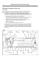
Installation
Installation
11
2
Machine foundation
The machines are designed to be bolted in
position to a concrete floor or specially prepared
concrete foundation. A template showing the size
of the foundation and positioning of the
foundation bolts is available.
For installation on an existing concrete floor, the
floor must be at least 8'' thick and of good quality.
If the floor does not meet these requirements,
then a high concrete foundation should be made.
Refer to "Technical data" for static and dynamic
floor loading.
1755
3
Follow the instructions below when making a
concrete foundation:
Fig.
2
Fig.
3
1. Decide where to place the machine and
consider maintenance requirements, i.e.
determine a suitable distance from the rear of
the foundation to the wall, and the distance
from the foundation to the nearest side wall.
The distance should be at least 16 and 2
inches, respectively.
2. Break up the floor to a depth of at least
3 inches, making sure that the sides of the
hole slope inwards - the bottom of the hole
should be 5 inches longer than the upper
length.
0272
4
3. Wet the hole well. Brush the bottom and sides
with cement grout.
4. Prepare a casing and fill with concrete to form
foundation. Make sure the foundation is level.
Fig.
4
5. Use the template to position the foundation
bolts correctly - bolts are to extend 1 1/2''
above concrete.
Reinforcing ironrods (A) shall be used around the
base. The ironrods shall be placed between the
bolts and the edge of the foundation.
1756
Installation
12
EXSM 230 S
Measurements for foundation in inches and (mm).
Fig.
5
A 39 (990)
I
B 37 (940)
K 4 29/32 (125)
C 36 3/8 (925)
L 31 1/2 (800)
D 33 7/8 (860)
M 32 1/2 (825)
E 3 3/4 (95)
N 35 11/32 (898)
F 6 5/16 (160)
O 38 3/4 (985)
G 7 7/8 (200)
P 41 27/32 (1063)
6 5/8 (168)
H 8 5/32 (207)
5
K
I
P
O
D
C
N
H
M
L
G
E
Front of machine
F
Front of foundation
B
A
2155
Installation
13
EXSM 350 S
Measurements for foundation in inches and (mm).
Fig.
6
A 42 29/32" (1090)
H 3" (77)
B 43 15/64" (1100)
K 36 13/16" (935)
C 3" (75)
L 37 1/64" (940)
D 3 15/16" (100)
M 41 9/16" (1056)
E 15 23/64" (390)
N 43 17/32" (1106)
F 3 15/16" (100)
O 51 59/64" (1319)
G 13 25/64" (340)
P 7/8" (22)
6
G
I
F
O
P
B
N
E
M
L
D
H
K
C
Front of machine
A
2340
Installation
14
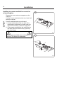
Mechanical installation
Fig.
7
7
• Place wide steel shims on the concrete
foundation over the bolts.
• Lift the machine and lower it in position. Never
use the door or the door handle to lift or lower
the machine.
Fig.
8
Fig.
9
Fig.
10
• Check that the machine is level front-to-rear
and side-to-side and standing firmly on the ten
supporting points. Spacing washers must be
mounted if one or more of these points is not
resting against the floor/foundation.
• Place flat washers over the foundation bolts
and secure the machine in position by
tightening the self-locking nuts. See illustration
below.
1757
• Tighten the nuts in sequence as shown.
• Check and tighten the nuts every week for the
first month.
8
10
EXSM 230 S
1758
2408
9
EXSM 350 S
2399
1759
Installation
Electrical installation
15
11
Although the machines are fitted with a thermal
overload in the motor windings and fuses for the
control circuit, a separate circuit breaker must be
installed for each machine.
For proper overcurrent protection, check the data
plate at the rear of the machine. Also consult
local electrical code for special requirements.
L1
The machine is equipped with a control circuit
transformer, mounted on the control unit and
connected for 220 volt operation.
If your incoming voltage is below 210 volts move
the wire connection to the 208 volt tab on the
transformer. If it is above 230 volts move the wire
to the 240 volt tab on the transformer.
Fig.
11
Connect L1, L2 and ground wires according to
the markings of the terminal block. The cable is
to hang in a large loose loop, supported by the
clamp below the terminal block.
L2
4940 A
Installation
16
Connection of external units
(optional equipment)
12
1 2 3 4
1 2
12 34 12
1 2
12 34 12
X148-1
X146-1
Electrical installation must be carried out
by an authorized personnel!
1 2 3 4
X149-1
All optional equipment connected must be
EMC-approved to EN 50081-1 or EN 500822.
Fig.
12
471 76 97 01
5 6 7 8 9 10 11 12
1 2 3 4
1 2 3 4
5 6 7 8 9 10 11 12
X147-1
12 3 4
1 2 3 4
X145-1
X144-1 471 75 96 01
Connector X149-1.
Connector for external START/STOP/PAUSE
function for machine.
Connector X148-1 (only on machines with at
least two I/O boards).
Connector for external buzzer or signal.
Connector X146-1.
Connector for external liquid supply pumps.
Control signals on 1-4 on left and Neutral to be
connected to 1 and Phase to 2 on right-hand
side.
Connector X147-1 (only on machines with at
least two I/O boards).
Connector for additional external liquid supply
pumps.
Connector X145-1 (only on machines with
three I/O boards).
Connections for recycling system 2.
Connector X144-1 (only on machines with at
least two I/O boards).
Connections for recycling system 1.
4940 B
Installation
Water connections
17
13
2
All plumbing must conform to national and
local plumbing codes.
All intake connections to the machine are to be
fitted with manual shut-off valves and filters, to
facilitate installation and servicing. The machine
is equipped with an integral air gap (siphon
braker) which complies with backflow preventions
requirements in most locations. In certain cases
non-return valves will need to be fitted before the
machine to comply with local plumbing
regulations.
Water pipes and hoses should be flushed clean
before installation. After installation hoses should
hang in gentle arcs.
The machine may have between two and four DN
20 (R 3/4") water connectors. All connectors
present on the machine must be connected up.
All water connectors must be connected up,
otherwise the wash program will not function
correctly.
Hoses are to be of an approved type and grade,
to comply with national regulations.
The water pressure data is as follows:
• min:
40 kPa (0,4 kp/cm2)
• max:
1 MPa (10 kp/cm2)
• recommended:
200-600 kPa (2-6 kp/cm2)
Water type
Water connection
1
Fig.
13
cold and hot
2
cold hot
3
cold or hot
1
3
4705
Installation
18
Drain connection
Fig.
14
14
Connect a 3'' (75 mm) flexible hose to the drain
outlet of the machine.
The drain hose must not have any sharp bends
and must slope from the machine to assure
proper drainage. The outlet must open freely to
the main drain.
Do not reduce the size of the drain connection
from the machine to the waste line.
1761
Installation
Steam connection (optional steam heating)
Fig.
15
The steam inlet pipe must be fitted with a manual
cut-off valve in order to facilitate installation and
service operations.
Attach the filter supplied with the machine to the
manual cut-off valve.
Conncection hoses should be of the quality
required according to regulations in the country
of use.
Connections size at filter: DN 15 (1/2'').
Steam pressure required:
• minimum: 50 kPa (0.5 kp/cm2) (7 psi)
• maximum: 800 kPa (8 kp/cm2) (113 psi)
Check there are no sharp angles or bends in the
connection hose.
19
15
20
Installation
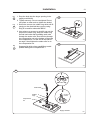
Installing top-mount manifold for connection
of liquid supplies
16
Remove the cover and cover support over the
soap box.
If comp 3 has a metal plate at the rear, bend it all
the way as shown.
Fig.
16
Fig.
17
Pull the manifold knobs up and forward.
1. Loosen both knobs so that one side of the
metal fingers underneath can slide under the
top lid of the machine, within the supply box.
2. Fit the supply manifold into the supply box so
that both sides are held securely in place by
the metal fingers.
3649
If the supply manifold does not fit turn it
around. You have it in backwards.
17
1
2
3648
Installation
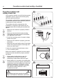
Fig.
18
1. Drop the knob into the larger opening in the
supply manifold lid.
21
18
2. Tighten securely. Do not overtighten! Do not
use pliers or other tools to tighten the knobs!
Fig.
20
1. Select the correct size rubber ring which will fit
snugly on the chemical tube you are using.
Ring A is used for tubes with Ø5/16''.
2. Use scissors or a razor to carefully cut out the
proper size rubber ring. Wrap the rubber ring
around each tube after threading each tube
through the strain relief. Run the tube through
the compression nut to the bottom of the soap
box compartment. Cut the end of the tube at
an angle. Hand tighten the strain relief on to
the compression nut.
Fig.
19
1
3647
19
Separate lid which gives possibilities to add
powder detergent in compartment 1.
3641
20
1
Multi-rubber ring
Strain relief
2
Rubber A
rings
B
Cut to fit
on tube
Compression
nut
Supply manifold
3643
22
Function control and safety checklist
Function control and
safety check list
21
In the machine cylinder, you will find the warranty
registration card, a copy of the warranty policy
and other pertinent material.
The warranty card should be completed and sent
to Wascomat. All other items should be placed in
a safe place for future reference.
The machine should be cleaned when the
installation is completed, and checked out as
detailed below without loading the machine with
fabrics:
Fig.
21
Fig.
22
1762
22
• Make sure the machine is properly bolted to
the floor..
• Make sure that all electrical and plumbing
connections have been made in accordance
with applicable local codes.
1. Check the incoming power for proper voltage,
phase and cycles.
• Make sure the machine is properly grounded
electrically.
4948
• Make sure that only flexible water fill and drain
hoses of the proper length to avoid sags and
kinks have been used.
23
2. Open the maunal water and steam valves.
3. Turn on electric power.
Before the machine is operated, the door safety
interlock must be checked for proper operation
as follows:
Fig.
23
Fig.
24
• When washer loading door is open, the
machine must not start. Verify this by
attempting to start washer with door open.
• When washer is in operation, the loading door
is locked and cannot be opened. Verify this by
attempting to open the loading door when the
machine is operating. If necessary, consult
this manual for proper operation of the door
lock and door safety interlock or call a
qualified serviceman.
4944
24
Door safety interlock must be checked
daily in accordance with above procedure.
4945
Function control and safety checklist
Add detergent and softner.
Choose a program.
Press START to begin test cycle The machine will start up and the display
window will show cycle information.
Check that:
• the drum is rotating normally at all program steps and that there are no
unusual noises.
• there are no leaks from the water/steam connections and the drain valve.
• the detergent/conditioner compartments are flushed down.
• the door cannot be opened during the program and not until after the program
has finished.
Fit the panels and covers removed during installation. Wipe the machine clean
with a damp cloth.
If no problems were encountered, the machine is ready for use.
All machines are factory tested prior to shipment. Occasionally, some
residual water may be found when the machine is installed.
Before servicing Wascomat equipment, disconnect electrical power.
23
Safety rules
24
Safety rules
• This machine is designed for water washing only.
• All installation operations are to be carried out by qualified
personnel. Licensed personnel are necessary for all electric
power wiring.
• The interlock of the door must be checked daily for proper
operation and must not be bypassed.
• All seepage in the system, due to faulty gaskets etc., must be
repaired immediately.
• All service personnel must be fully familiar with the operating
manual before attempting any repair or maintenance of the
machine.
• This machine must not be sprayed with water, otherwise short
circuiting may occur.
• This machine must not be used by children.
• Fabric softeners with volatile or inflammable fluids are not to be
used in the machine.
Consignes de sécurité
• La machine est conçue pour le lavage à l'eau exclusivement.
• Tous les travaux d'installation doivent être effectués par une
personne qualifiée. Tous les câblages électriques doivent être
réalisés par un électricien diplômé.
• Le verrouillage du hublot doit être vérifié chaque jour et ne peut
être neutralisé.
• Toute fuite du système, due à des joints défectueux etc., doit
être réparée sans délai.
• Tous les membres du personnel d'entretien doivent être
parfaitement familiarisés avec le manuel d'entretien avant
d'entreprendre une réparation ou un entretien de la machine.
• Ne jamais asperger d'eau la machine sous peine de risquer un
court-circuit.
• La machine ne peut être utilisée par des enfants.
• Ne pas utiliser dans la machine des adoucissants textiles
contenant des liquides volatils ou inflammables.
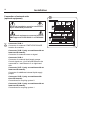
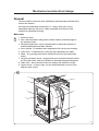
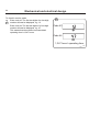
Mechanical and electrical design
25
General
The door and the electronic timer with display and keyboard are fitted at the
front of the machine.
All control and indicating components, i.e. relays, delay unit, etc are
assembled under the top cover, easily accessible from the top of the
machine for simplified servicing.
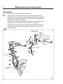
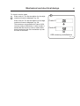
Main units
Fig.
25
1 Electronic timer.
2 Door -with automatic locking device which remains locked throughout
the wash processe.
3 Detergent supply box - three compartments for automatic injection of
powered detergents and fabric softener.
4 Inner cylinder - of stainless steel supported at the rear by two bearings.
5 Outer drum - of stainless teel (18/8) securely attached to the frame.
6 Motor - for reversing wash action, distribution and for high speed spin
action.
7 Hot and cold water valves - program and level controlled solenoid valves
for filling with water, and for flushdown of automatic detergent dispenser.
8 Drain valve - timer controlled valve for draining the machine of water.
9 Control circuit - of plug in type, for time and temperature control of the
different wash cycles.
25
7
3
9
1
5
4
2
6
8
4941
Mechanical and electrical design
26
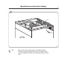
Machine construction
Panels
The machines are equipped with a top panel and front panel made of
stainless steel. Colored panels are made of phosphatized steel.
For servicing purposes, the panels can be easily removed.
Outer shell
Fig.
26
The outer shell is made of heavy gauge surgical steel and is attached to a
heavy duty, rigid head casting (back gable).
The whole assembly is mounted on a heavy gauge fabricated steel base,
hot-dip galvanized for long life and corrosion resistance.
Inner cylinder
The inner cylinder is made of perforated surgical stainless steel. It is
equipped with three lifting ribs and has highly-polished side sheets and
back with maximum embossed perforated area to assure high flow of water
and supplies through fabrics.
Scientifically correct ratio of cylinder diameter and depth assures maximum
washing action.
The shaft is electrically welded to the reinforced back of the cylinder. A
specially designed chrome plated sleeve bushing protects the seals from
wear.
26
4941
Mechanical and electrical design
27
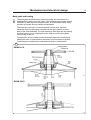
Back gable and bearing
Fig.
27
The back gable and the bearing trunnion housing are constructed of a
webbed heavy casting for extra rigidity. The bearings are protected against
infiltration of water by three neoprene seals. An intermediate safety outlet
provides an escape for any possible condensation.
The seals are mounted on a chrome-plated, noncorrosive, specially
hardened sleeve bushing that is mounted on the drive shaft to prevent
wear of the seals and shaft. The main bearing is fitted tight into the bearing
trunnion housing. A nut is tightened on the shaft to prevent the cylinder
from moving in and out.
The extension of the bearing trunnion housing supports the rear bearing
holding the shaft. A grease seal is mounted to prevent escape of grease.
The bearings are permanently lubricated and need no maintenance.
27
EXSM 230 S
5014
EXSM 350 S
5015
Mechanical and electrical design
28
Description
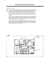
The machine door lock consists of the following:
Fig.
28
• The locking unit, located behind the front panel below the detergent
dispenser. The unit consists of a solenoid which locks the door, and two
microswitches. Switch S4A indicates that the door is locked and switch
S3 indicates that the door is closed.
• The door lock control unit, located in the automatic control unit. This unit
consists of a circuit board for monitoring door lock functioning.
• The locking arm, located between the door lock handle and the locking
unit. This arm provides the mechanical link between door lock handle
and locking unit.
28
Locking unit
Safety switch S3
Switch
S4A, B
Actuator
Rocker arm
Locking arm
Door lock
handle
101640
101637
Mechanical and electrical design
29
Door lock control unit
Fig.
29
The sole function of this control unit is to oversee the correct functioning of
the door lock. The CPU board receives information from the motor control
unit about motor rotation, and has its own level-monitoring device. The
control unit also detects water level and motor speed through separate
level measurement devices and the rotation guard (speed-monitoring
device). Through this double monitoring, a very high level of safety can be
achieved.
When the CPU board commands door locking, the control unit checks that
there is no water in the drum and that the drum is not rotating. Only after
that is a signal sent to the door lock. Level and rotation are checked in the
same way before the door is allowed to open.
For even greater safety, the voltage feed to the I/O boards’ outputs goes
via both the emergency stop and the door lock switch. This means that no
functions can proceed unless the emergency stop is in its normal position
(not actuated) and the door is locked.
29
Red LED,
an indicator
Door lock control unit
X90
X91
X92
Relay RE3
X96
X95
X94 X93 X99 X98
X97
4697
Mechanical and electrical design
30
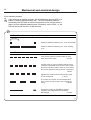
Error indication patterns
Fig.
30
If the door lock is working correctly, this is indicated by the red LED, by a
pattern of flashes which indicates “OK”. The error indication patterns
revealed by the LED flash at various frequencies for the various errors or
faults. All error indication patterns have a frequency cycle of 50%, i.e. the
LED will be on half the time, off half the time.
30
LED pattern of flashes during normal functioning
1 second
Pattern of flashes indicating “OK”, drum at standstill
Pattern of flashes indicating “OK”, drum rotating,
5 Hz
Error indication pattern
Meaning/cause
Level-sensing device indicates water in drum
when door lock is open.
2.19 Hz
Auxiliary relay for motor indicates that the motor
contactor is activated when the door lock is open
(this error indication pattern does not occur when
the excess-speed-monitoring device is selected).
1.88 Hz
Signals from rotation sensor and auxiliary relay
do not correspond.
1.56 Hz
The control unit sensor circuits indicate fault/
error in drive circuits for door lock including its
wiring.
0.85 Hz
Armament circuits for RE1/RE2 activated
(capacitor C8 charged when it should be
discharged).
0.37 Hz
4686
Mechanical and electrical design
31
31
E10
4942
Fig.
31
E10
Motor control unit, microprocessor-controlled. Controls
direction of rotation and speed of motor. The MCU is also
used for imbalance detection and calculating weight of wash
load.
32
Control unit
Mechanical and electrical design
Mechanical and electrical design
33
Supply unit
33
F22 F21
F12
K22
F11
K21
X146
L1
X1
L2
1234512
12345 12
X146-1
471 75 98 01
4989
Fig.
33
F11, F12
Fuses, incoming power supply
F21, F22
Fuses, motor control unit
X1
Main input
K21, 22
Heating relays (only if heated)
Mechanical and electrical design
34
Motor
Fig.
34
34
In machines with a frequency control the same
motor is used for wash speed, distribution speed
and extraction. The motor is located on a motor
mounting plate, and drives the drum via a belt.
The tension of this drive belt can be adjusted by
moving the entire motor in the mounting slots on
one side. The motor has a thermal cut-out
located in its windings. The status of this thermal
cut-out is deffected by the motor control unit
causing it to shut itself off, in the event of the
motor overheating, i.e. if the temperature
exceeds 130°C.
The various motor speeds for normal action,
distribution and extraction are controlled by a
microprocessor-based motor control unit (MCU).
The control signal for the motor control unit goes
via a speed selector, which the operator can also
use to select specific extraction speeds for low
and high extraction.
4939
Mechanical and electrical design
Repair instructions
35
35
Overheated motor, motor not running
• Wait until motor has cooled down. Motor
guards are automatically reset after 30
minutes. Restart, machine.
• Possible cause of motor guards releasing
repeatedly: Low voltage, faulty windings,
faulty bearings.
A
Very noisy motor
• Breakdown of bearings – replace motor.
F
Motor locks
2311
Breakdown of bearings – replace motor
Motor does not turn
Fig.
35
• Check belt tension.
When checking the belt tension or when
changing belt, use the adjustment data provided.
Checking the belt tension should always
be a part of the regular maintenance.
A m ax
15 mm
9/16 in
A min
15 mm
9/16 in
F
25 N
60 lbs
Mechanical and electrical design
36
Motor control unit E10
36
X312
X301
X302
X304
X308
LC2
X311
4744
Fig.
36
LC2
Suppression filter
Connectors
X301
Serial communication with PCU
X302
Input, lock confirmation
X304
Relay output
X308
Imbalance input
X311
Main power input
X312
Connection, motor and thermal protection device (Klixon)
Mechanical and electrical design
37
Motor control unit
Fig.
37
Fig.
39
The motor control unit communicates with the PCU board via a serial
duplex interface. With the aid of the MCU, the PCU can not only control the
speed the motor is to have at any given moment, but also control the
acceleration and deceleration rates the motor will use to reach the speed
commanded. The MCU constantly relays information back to the PCU
board on current operating status, e.g. whether everything is proceeding
without problems or if a fault or error has arisen.
The MCU can also supply data on the torque of the motor at constant speed
and when accelerating and decelerating. This data is used both for
calculating the weight of the wash load and for detecting any imbalance
present.
Take great care when using measuring instruments on the MCU,
since all components have a potential difference of approx. 300 V in
relation to earth and neutral.
The MCU will not be de-energised until 10-30 seconds after the
machine is isolated from the power supply and the motor has
stopped.
The green LED on the MCU board will remain lit for as long as there
are hazardous voltages present in components.
37
Serial communication
X301
Main input
X311
Relay output
X304
X312
PCU
Motor
Motor
control unit
Input
lock sequence
X302
X312
Door lock switch
230 V AC
4711 A
Mechanical and electrical design
38
There is a cooling fan on the MCU. The fan starts up automatically when
the heat sink reaches a temperature of approx. 65°C, which can arise
during extraction if the load is unfavourable or if the ambient temperature is
high. When the machine power supply is first switched on the fan operates
for a short time.
The MCU has an interlock signal input connected to a switch in the door,
which supplies the input with main voltage when the door is locked.
PCB connector/Function
X301: Serial communication
Communications between MCU and CPU. With an interface it is
possible to connect a PC for testing machine operation/functions.
X 301:2 Gnd
X 301:3 Txd
X 301:4 Rxd
X302: Input lock confirmation
An input voltage of 96-276 VAC is required to start the motor.
The function of this input is to stop/not start the motor when the door
lock is open.
Input voltage: 120 V-20 % (=96 V) - 240 V+15 % (=276 V), 50/60 Hz
Current:
Max. 0.01 A
X304: Relay output
The relay is controlled via commands from the PCU (X301). The relay is
not to be activated if communication with the PCU is lost.
Isolation voltage:
Voltage:
Current:
Relay connections:
Connector:
3750 V
250 VAC
max. 2 A
1-pole, 2-way (three connections)
X304:1
X304:2
X304:3
Normally open
Normally closed
Common
X307: Internal
This contact is used for connection of a fan for cooling the MCU.
Mechanical and electrical design
X311: Main power input
Input voltage: Single-phase or DC three-phase: 200 V-15%(=170 V) 240 V+10% (264 V)
X312: Output to motor and input thermal protection device (Klixon)
The output is connected to a thermal protection device, located on the
motor windings, with a connection back to the input. If the motor
becomes overheated, the thermal protection device switch opens. The
yellow LED reveals an error code through its pattern of flashes, see the
section “Error indication patterns”.
Current, max. 0.01 A
39
Mechanical and electrical design
40
Error indication patterns
If a fault or error occurs in the motor or motor control unit, the MCU sends
an error signal to the CPU board. In addition to an error code showing on
the display, errors/faults are revealed by the flashing of a yellow LED on the
MCU board. The table below shows how to identify the error/fault on the
basis of the flashing pattern of this LED.
Fig.
38
Fig.
39
38
LED pattern of flashes
Error code/message
on display
Cause
1
HEAT SINK TOO HOT
Heat sink on MCU too hot.
2
MOTOR TOO HOT
Motor thermal protection device activated
3
NO INTERLOCK
MCU has received start command,
but not received interlock signal.
NO MOTOR COMM
Communication error MCU – PCU
–
Short in motor windings, wiring or internally in
MCU. MCU will restart automatically.
MOTOR SHORT
Once again short in motor windings, wiring or
internally in MCU.
7
INTERL HARDWARE
Fault in interlock circuits in MCU.
8
LOW DC VOLTAGE
MCU DC voltage too low.
9
HIGH DC VOLTAGE
MCU DC voltage too high
10
RIPPLE DC BUS
Ripple DC-bus (EWD 4000 only).
11
KLIXON CIRCUIT
Fault/error in MCU overheating circuits.
4
5
6
approx. 5 seconds
4710
Mechanical and electrical design
41
Fault-finding
There are fault-finding charts for all error codes in Chapter 12, “Faultfinding”.
39
X312
X313
In 170 and 220 l
machines only
X301
X302
X311
X308
X304
Yellow LED
Green LED
Error indication patterns, green LED
Fig.
40
The green LED on the MCU board is normally lit except for a brief pause
approx. once every five seconds (pattern which indicates “OK”).
When the microprocessor for the PCU is removed from the machine or has
reset status, the LED will be lit without flashing.
When the MCU current-limiting function is activated, the LED will instead
flicker, and the flashing pattern which indicates “OK” will be suspended for
as long as the current-limiting function is activated. When the MCU currentlimiting function ceases, the pattern of flashes indicating “OK” will return
after 10 seconds.
40
Pattern indicating “OK”
approx. 5 seconds
4712
Flickering when MCU current-limiting
function is activated.
4708
Mechanical and electrical design
42
Extraction
Fig.
41
During extraction, the motor speeds follow an extraction sequence which is
always the same. This extraction sequence is used for all standard
programs 991-999 for CLARUS machines.
The table shows the extraction speeds during the various phases of the
sequence, for various drum volumes.
The extraction sequence is as follows:
Phase 1.
Distribution period of 40 seconds, with imbalance
sensing. Imbalance sensing takes place during the
last 5 seconds.
Phase 2.
Extraction for 30 seconds.
Phase 3.
Extraction for 30 seconds.
Phase 4.
Extraction for 30 seconds.
Phase 5.
Extraction for remainder of the program’s total
extraction time.
41
Mechanical and electrical design
Imbalance measurement
At the start of every extraction sequence the system monitors variations in
the motor torque while the drum is operating at distribution speed. If these
variations are too great, it indicates that the load is unevenly distributed in
the drum. At this point extraction is halted, the motor speed is reduced to
wash speed and a fresh attempt to begin extraction starts. This procedure
will be repeated up to three times per extraction. After the third time the
system will decide whether the imbalance is “great” or “small”.
• If the imbalance is “great”, the extraction stage of the program will end
without extraction having taken place.
• If the imbalance is “small”, extraction will take place, but at a reduced
speed.
43
Mechanical and electrical design
44
Supply injection valve
42
Construction
Fig.
42
The valve has a single-inlet with either one, two
or three outlets, each with its own solenoid coil.
The body is made of heat-resistant polyamid
plastic and the solenoids encased in water-tight
plastic. The electrical connector terminals are
spade lugs.
A filter screen on the inlet side prevents dirt from
entering the valve. Flow restrictors can be placed
at either the inlet or any of the outlets.
Operation
Fig.
43
When the solenoid is energized, the springloaded plunger is drawn up and the pilot valve in
the centre of the diaphragm open. Because of the
difference in diameter between the pilot valve
opening and the ventilating hole in the
diaphragm, the pressure above the diaphragm
drops to a point where the admission pressure
below the diaphragm can lift the diaphragm, thus
opening the valve.
When the current to the solenoid is cut off, the
plunger spring will press the plunger against the
pilot opening of the diaphragm. The pressure
above the diaphragm then rises to correspond to
the water inlet pressure and the pressure of the
spring will close the valve.
1161
43
solenoid
plunger
ventilating hole
diaphragm
pilot valve
1185
Mechanical and electrical design
Repair instructions
45
44
Limescale can block the hole in the valve
diaphragm and interfere with the function of the
valve.
Fig.
44
It is therefore advisable to dismantle and clean
the valve at certain regular intervals. The
frequency depends on operating conditions and
the level of contamination in the water.
If the valve does not open
• Check that power is supplied to the coil.
• Check the coil with an instrument to determine
whether there is a break or a short circuit.
• Dismantle the valve (see below) and check
the openings in the valve diaphragm.
• Check the inlet strainer and clean as required.
1186
45
• Undo the coil and clean the surfaces of the
magnetic core.
If the valve does not close
• Check that the coil is not live. The valve is
normally closed when the magnet is not
energised.
• Check the return spring.
• Check the diaphragm (pilot pressure opening).
Dismantling the valve.
Fig.
45
Fig.
46
• Pull the coil straight upwards. Use a
screwdriver if necessary to carefully undo the
coil.
• Use the tool supplied (attached to one of the
hoses when the machine is delivered) to open
the valve housing. Slide the tool over the
protruding plastic sleeve to that the pegs on
the tool engage the corresponding sockets in
the valve housing.
1187
46
• Use a spanner or a pair of pliers and unscrew
the upper part of the valve housing.
1181
Mechanical and electrical design
46
Inlet valve
Fig.
47
47
The water inlets have brass bodies with larger
cross section of the outlet in order to achieve a
shorter filling time for the machine.
Construction
Fig.
48
The valve housing is made of pressed brass. The
spring-loaded plunger is made of stainless steel
and located at its lower end.
Operation
The valve is automatically operated by means of
a rubber diaphragm and a pilot valve in exactly
the same way as the supply injector valve.
3963
To strip, clean, re-assemble and
troubleshoot the inlet valve, follow the
instructions outlined for the supply injector
valve.
48
Coil
Spring
Plunger
Body
Diaphragm
3961
Mechanical and electrical design
Description
Fig.
49
Fig.
50
47
49
The drain valve is a motor-operated diaphragm
valve which allows rapid emptying thanks to its
large cross-section. This is a self-clearing design,
so there is no need for a lint filter.
Main parts of the valve:
• motor plus gear
• piston rod with trapezoidal thread, plus piston
and return spring
• rubber diaphragm
• connections for water filling, overfilling, drain
In its open state, the valve is not energised. In
this state the piston rod is screwed down to its
lowest position by the return spring. The
diaphragm is pressed downwards with the piston
and the valve is open.
4747
50
Connection for
water filling
Riser to wash
drum
Nipple for sensor hose
for level control
Diaphragm closed
position
Diaphragm open position
Piston rod
Guide pin
Return spring
Motor
Gear wheel
4748
48
Mechanical and electrical design
When the motor is activated and begins to rotate, the piston rod is turned
upwards via the gear, the diaphragm is pressed upwards with the piston
and presses against the valve seat: the valve closes.
The connection for overfilling is connected to the upper part of the wash
drum, water and foam are diverted straight to the drain if the intake valves
or level control should malfunction.
On the riser for the wash drum are the connection for water filling and a
nipple for connecting the sensor line for the level control.
Instructions for repair
Deposits on the diaphragm can prevent the valve from opening or closing
properly. The valve should therefore be cleaned at certain intervals,
depending on operating conditions and water quality.
If the valve is not opening or closing properly:
Fig.
51
• Check that the motor has the right input voltage.
• Check that the piston rod can move freely.
• Check whether the diaphragm is clogged with deposits.
To note if replacing the motor:
Brown cable: 60 Hz
Blue cable: common
Black cable: 50 Hz
Mechanical and electrical design
49
Tensioning of return spring
With the valve housing removed:
- Turn the return spring so that the “tongue” of the spring is resting against
the stop screw.
- Position the valve housing over the return spring so that the pin on the
spring will fit into the recess on the piston rod. (Note: the piston rod
should be installed so its recess is aligned along the housing.)
- Then turn the housing one turn clockwise. (This will screw the pin of the
spring into the piston rod. The spring will be now tensioned approx. 1/4
of a turn on account of the lead in the piston rod.)
51
Stop screw
Tongue of spring
Pin of return spring
4749
Mechanical and electrical design
50
Soap supply box
Fig.
52
The three-compartment soap supply box is located at the top of the machine.
Viewed from the front, the compartments marked with figures 1, 2 and 3 are used
as follows:
Compartment 1
This compartment is used for adding detergent directly to the wash at the
beginning of a cycle or at any time during the cycle when extra supplies are
required.
Compartment 2
This compartment is the main compartment for adding detergent to the wash .
Compartment 3
The small compartment is used for adding fabric softener. The fabric softener is
flushed down with water by overflowing when the injection of fabric softener is
called for.
When using a top mount supply injector connection only compartment 2 will be
utilized.
52
1182
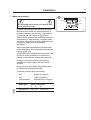
Operating instructions
51
Operating instructions
The Emerald Series program unit controls the various functions of the machine
in a certain time sequence with the aid of seven built-in standard programs.
The standard programs can also be modified by selecting various options. By
selecting options, the user has access to programs for all types of wash loads
and degrees of soiling.
Fig.
53
The control panel consists of program selection buttons (A) and (B), a
combined start, pause and rapid advance button (C), symbols with LEDs (D)
which show the program selected and the program sequence, plus an alphanumeric display (E).
The alphanumeric display shows illuminated green characters.
In the event of faults, error codes will be displayed on this window. See Fault
codes.
53
A
E
Supply
signals
1
2
1
5
2
6
3
7
4
START
STOP
3
4
Program
step
5
Prewash
Mainwash
Rinse
Final extract
Doorlock delay
Door unlocked
D
B
A
B
Explanation of control panel
A Program selection buttons
B Option buttons
C Start/pause and rapid advance button
D Symbols with LEDs to indicate program sequence
E Information display
C
4996
Operating instructions
52
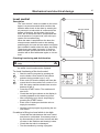
Washing
Fig.
54
• Press the button for the desired program.
55
• Now the LEDs alongside the program symbols will show what the selected program
consists of.
Fig.
• Press the button(s) for any options required.
Fig.
54
1
Hot
5
Perm Press
2
Warm
6
Quick-Wash
3
Cold
7
Heavy Soil
4
Delicate
56
START
3426
Fig.
57
Fig.
Gentle actions consists of 6 seconds
rotation, as opposed to 18 seconds pause
and 6 seconds pause and 14 seconds
rotation for Normal action.
55
Supply
signals
1
2
3
4
• Press the START button.
58
5
Prewash
Mainwash
Rinse
Program
step
Final extract
Doorlock delay
Door unlocked
4995
56
A
57
B
58
START
3435
Operating Instructions
Fig.
59
• Now the display will show the clock symbol
and two digits. The two digits are the time left
before the wash will be finished.
53
59
The two digits indicating time left will not
appear when the machine is first installed.
Each program needs to have been used at
least once before the time left will be displayed.
3141
• For 5 minutes immediately after START is
pressed the colon character (: ) will flash on
the display. As long as this character is still
flashing a new program can be selected
(without the drain opening). This means you
still have the chance to change the setting if
the wrong program has been selected. Do as
follows:
Fig.
60
60
1
• Press START.
• Select a new program.
• Press START again after making any change
in the program selected.
4091
Fig.
61
If for any reason you wish to halt the wash cycle
for a time, press the START button for a moment
or two. The program will be suspended and the
drain will remain closed.
To restart the program, press the START button
again briefly.
61
START
3435
Operating Instructions
54
For coin-operated machines
Fig.
62
Fig.
63
62
Select a wash program, then insert the number
of coins corresponding to the figure shown on
the display.
As each coin is added the machine counts
backwards towards 00 on the display. The
machine will not start until the display shows 00.
• Press the START button.
• Now the display will show the clock symbol
and two digits. The two digits are the time left
before the wash will be finished.
2253
63
The two digits indicating time left will not
appear when the machine is first installed.
Each program needs to have been used at
least once before the time left will be displayed.
Fig.
64
• For a time immediately after START is pressed the colon character ( : ) will flash on the
display. As long as this character is still
flashing a new program can be selected
(without losing anything). This means you still
have the chance to change the setting if the
wrong program has been selected.
START
3435
64
• Press PAUSE/START.
• Select a new program.
• If the new program costs more to run than
the amount already paid, the difference will
be shown on the display. Insert enough coins
to make the display show 00 again.
• Press START again after making any change
in the program selected.
3141
Operating Instructions
Rapid advance
65
Whole steps in programs can be skipped using
rapid advance.
Fig.
65
55
START
• Press and hold the START button until the
program indicator LEDs have moved past the
program steps you wish to skip.
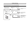
Program end
Fig.
66
Fig.
67
After final extraction, the LED by the "doorlock
delay" comes on. This shows that the door lock
will shortly be unlocked.
The door will not actually be unlocked until the
green LED by the "door unlocked" comes on,
accompanied by an audible signal. This takes
about 1 minute.
3435
66
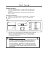
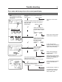
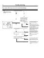
Troubleshooting
If the machine won’t start, check that:
Doorlock delay
• the circuit breaker is on.
Door unlocked
• the manual shut-off valves for water are open.
• a program has been selected.
• the door is properly locked.
3424
67
Doorlock delay
Door unlocked
3425
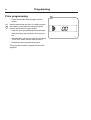
Programming
56
Coin-operated machines
68
In coin-operated machines the prices for the
various programs have to be programmed in.
Values from the coin mechanism (the
accumulated value) can be read out with the aid
of the service program.
If a machine is fitted with a coin mechanism after
its original installation the relevant electronic
circuitry will have to be activated before the prices
can be programmed in.
3400
Only trained service personnel may use the
service program and program in prices for
coin operation.
Activation of electronic circuitry in machines fitted with coin operation after original
installation.
Fig.
• Press the service button.
68
Now certain of the buttons switch to being
number keys (1 to 9), with the START button
being 0.
Fig.
69
69
1
A
2
31
7
4
8
5
9
6
3429
Programming
Codes 91 and 92 are used to store the values for
coin slots 1 and 2. For mechanisms with only one
slot, only code 91 is used.
57
70
The values to be stored are the ratio of one coin
to the other.
For example: if the coin slots are for a 10 cent
coin and a 50 cent coin. The value 10 should be
stored under code 91, and the value 50 should be
stored under code 92.
Fig.
70
• Enter code 91 using the buttons which have
become number keys 9 and 1.
2275
The display will now show 91.
Fig.
71
Fig.
• When entering the actual value: keep the
price-programming button activated (the switch
is located under the top cover at the right front
edge). Enter the value 1 and then release the
button.
71
• Enter code 92. The display will now show 92.
72
Fig.
• Enter the value 5.
73
Fig.
74
2276
• Exit the service program by pressing the
service button again.
72
2272
74
73
3400
2274
Programming
58
Price programming:
75
• Press the relevant wash program selector
button.
Fig.
75
When programming the price of a wash program
plus options, press both the relevant program
selector button and the option button.
• Keep the price-programming button activated.
Now the display shows 00 plus the coin symbol.
2273
• Enter the price via the numerical key functions.
The START button can be used to enter 0.
• Release the price-programming button.
This procedure should be repeated for all wash
programs.
Wash programs
59
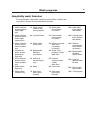
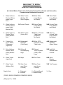
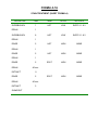
Hospitality wash formulas
For hotels/motels, restaurants, retirement communities, schools and
universities, commercial and institutional laundries.
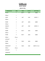
1 White uniforms
sheets & pillowcases (light
soil)
1A White towels
(medium soil
short program)
1B White table
linen (bleach,
no starch)
1AB White table
linen (bleach
and starch)
2 White uniforms
sheets & pillowcases (light/
medium soil)
2A Colored towels
2B Colored table
linen (bleach,
no starch)
2AB Colored table
linen (bleach
and starch)
3 White uniforms,
sheets, pillowcases (medium
soil)
3A White towels
(heavy soil)
3B White or colored
table linen
(no bleach,
no starch)
3AB White or
colored table
linen (starch,
no bleach)
4 Colored uniforms, sheets,
pillowcases
(light soil)
4A Bedspreads/
delicates
(cold water)
4B White 100%
polyester (VISA)
table linen
4AB Bedspreads/
delicates
(warm water)
5 Color uniforms,
sheets, pillowcases (medium
soil)
5A Kitchen &
housekeeping
rags
5B Colored
100% polyester
(VISA)
table linen
5AB Light soil
general wash
formula
6 White towels
(light soil)
6A Mops
6B Chef coats
6AB Extra rinsing
with extract
7 White towels
(medium soil)
7A Stain treatment (short
formula)
7B Stain treatment (long
formula)
7AB Test program
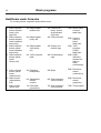
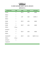
Wash programs
60
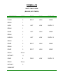
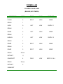
Healthcare wash formulas
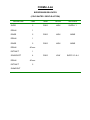
For nursing homes, hospitales and medical center.
1 White uniforms
sheets & pillowcases (very
light soil)
1A Diapers/pads
medium soil
1B Colored uniforms, sheets
& pillowcases
(light soil)
1AB White cotton
or blend
table linen
2 White uniforms
sheets & pillowcases (medium/
heavy soil)
2A Diapers/pads
heavy soil
2B Colored towels
2AB Colored
cotton or
blend
table linen
3 White uniforms,
sheets, pillowcases (medium/
heavy soil)
3A Diapers/pads
extra heavy
soil
3B Dietary and
kitchen rags
3AB 100%
polyester
(VISA)
table linen
4 White uniforms
sheets, pillowcases
(heavy soil)
4A 100% polyester
pads
4B Housekeeping
rags
4AB AIDS/
infectious
disease isolation in
water
soluble bags
5 Color uniforms
sheets, pillowcases
(medium soil)
5A Delicates/
bedspreads
5B Mops
5AB Rinse and
extract
(cotton/terry)
6 White towels
(light/medium
soil)
6A Sheepskins/
cubicle
curtains
6B Stain treatment
(short formula)
6AB Rinse and
extract
(polyester)
7 White towels
(heavy soil)
7A Personals/
general ldry.
7B Stain treatment
(long formula)
7AB Test program
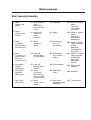
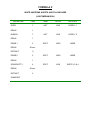
Wash programs
61
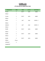
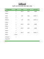
Shirt laundry formulas
1 Shirts
(starch, cold
rinses)
1A Short formula
shirts
(no starch)
(may use with
5 or 6)
1B Delicates
1AB White or colored
blend
table linen
(with bleach,
no starch)
2 Shirts
(starch, warm
rinses)
2A Heavy soil
shirts (one
starch
injection)
2B Mops
2AB White or colored
blend
table linen
(with bleach
and starch)
3 Shirts
(no starch)
(may use with
formula 5 or 6)
3A Shirts
(pause for
starch)
3B Extra heavy
soil – no –
iron fabrics
3AB White or colored
100% polyester
(VISA)
table linen
(white bleach,
no starch)
4 Shirts
(no starch, no
bleach) (may
use with
formula 5 or 6)
4A Light soil
general wash
no-iron fabrics
4B Extra heavy
soil – cotton
fabrics
4AB White or colored
100% polyester
(VISA) table
linen (with
bleach and
starch)
5 One starch
injection
with extract
5A Light soil
general wash
(cotton)
5B Wool blankets
5AB White cotton
blankets
6 Two starch
injections
with extract
6A Shirts
(no starch,
short extract)
(may use with
formula 5 or 6)
6B Stain treatment
6AB Uniforms
7 Short rinse
and extract
7A Shirts
(starch, short
extract)
7B Stain soak
(supplies added
manually)
7AB Test program
Mechanical and electrical design
62
Electronic program control unit
Description
Fig.
76
The program control unit is electronic and consists of a circuit board with
components. On one half are the microprocessor, program memory
(EPROM), power supply circuits, temperature and level control devices and
so on. On the other half are the relays and interference suppression
components. The program control unit has the following inputs and outputs:
• Inputs reacting to push-buttons on the control panel.
• Inputs which provide information on the machine’s door lock status, level
control, temperature sensors and coin mechanism if installed.
• Outputs which via relays directly control the various functions of the
machine, e.g. motor control, water valves and door lock.
• Outputs to the display.
• Serial communication with the motor control unit.
The program control unit is controlled by the microprocessor, which fetches
its instructions from the program memory (EPROM). The EPROM contains
instructions for operation, the service program, control of relays, sensing of
inputs etc. The EPROM also contains the standard programs supplied with
the machine.
76
F1 (1A/250V)
For electronics
X72
Voltage feed
F2, F3 (1A/250V)
For display
X74
X77
Temperature X75
Motor control Coin mechanism
sensor
unit
X76
Price=zero
Buzzer
Relays
To
control
panel
Interference
suppression
components
Service switch
X71
Door lock
Level sensing
device
Microprocessor
X84
CP80
Program memory (EPROM)
X81
Valves
X83
Heating
X82
Valves
X78
Input voltage
X80
Valves
X79
Drain
2316
Mechanical and electrical design
Operating time, accumulated coin value,
EPROM no.
63
77
The machine’s built-in service program can be
used to check the machine’s accumulated operating time, the accumulated coin value (for coinoperated machines), and the program EPROM
part number.
Accumulated operating time
To check during normal operation
Fig.
The machine needs to be actually operating
77
(program selected and started).
The buttons identified as A and B in the illustration
may be ”concealed” on some machines, in other
words, have no symbols or other markings. They
will still be usable for this function, however.
A
This means that the machine’s accumulated
operating time is 1,347 hours.
B
A
+
Press button A. The first two digits of a four-digit
number will now be displayed, e.g. 13.
Press button B. The last two digits of a four-digit
number will now be displayed, e.g. 47.
2
1
B
=
1,347 hours’ operating time
2224 2241 2242
To switch on service mode
• Remove the machine top and the cover for the
program unit circuit board.
Fig.
78
Fig.
79
78
• Press the service switch. This switch is on the
left-hand edge of the circuit board when viewed
from the machine front. The display will now
show SE, which means that the service program is activated.
Service switch
Now some of the buttons switch to being number
keys (1 to 9). The start button becomes an ON/
OFF key.
To switch off service mode
Press the service switch again, or switch off the
machine power supply.
3400
79
1
A
2
31
7
4
8
5
9
6
3385
64
Mechanical and electrical design
To check in service mode
Fig.
80
80
Enter code 43. The first two digits of a four-digit
number will now be displayed, e.g. 13.
Enter code 44. The last two digits of a four-digit
number will now be displayed, e.g. 47.
Code 43
+
This means that the machine’s accumulated
operating time is 1,347 hours.
Code 44
=
1,347 hours’ operating time
2241 2242
Mechanical and electrical design
To check in service mode
Fig.
81
65
81
Enter code 41. The first two digits of a four-digit
number will now be displayed, e.g. 06.
Enter code 42. The last two digits of a four-digit
number will now be displayed, e.g. 58.
This means an accumulated coin value of 658
currency units or 658 tokens. In other words, it
shows that 658 currency units or tokens have
been inserted into the coin mechanism up until
the time of the check.
Code 41
+
Code 42
=
658 currency units/tokens
2240 2239
66
Mechanical and electrical design
Program EPROM part no. (check in service mode)
Fig.
82
Enter code 51. The letter A and two digits will be
displayed, e.g. A47. ”A” denotes part no. (article
no.).
82
Code 51
Enter code 52. The display will show (e.g.) 195.
+
Enter code 53. The display will show (e.g.) 803.
Enter code 54. The display will show (e.g.) 480.
When these digits are put together they make up
the full part number:
Code 52
+
A471 958034. The two digits at the end are an
internal version number.
Code 53
+
Code 54
=
A (=part no.)471 958034
80 (code 54) = internal
version no.
2238 2237 2236 2235
Mechanical and electrical design
Level control
67
83
Description
The "level control", which is located on the circuit
board, is a pressure switch which monitors the
different water levels in the drum by sensing the
air pressure in a tube which is connected to the
bottom of the drum. As the water rises in the
drum, the air inside the tube is compressed and
at a set pressure ("cut-out-level") the micro-processor cuts out water filing.
Service switch
When the water is emptied from the drum the
microprocessor switches back to the starting
position again, but now at lower water levels than
were needed to switch when the drum was filling.
These levels are called "on-levels". If during a
wash the water should sink below on-level, the
machine will be filled with water again, to cut-outlevel.
Checking functioning and fault location
3400
84
To be carried out by authorized personnel
only.
A faulty level control cannot be repaired. Instead
the whole circuit board must be replaced.
To check functioning of the level control
Fig.
83
Fig.
84
• Start the service program by pressing the
service button. Now certain of the buttons
switch to being number keys (1 to 9).
• Enter code 24. Now the display will show the
current level in the machine on a scale of 1 to
200. An empty machine should show a value
between 0 and 4.
1
A
2
31
7
4
8
5
9
6
• Press the START button. The machine will
start to fill.
• Check that the figure shown on the display is
counting upwards as the water level rises.
• After completing your check, stop filling by
pressing the START button.
• Enter code 21 and open the drain valve to
empty the machine.
• Quit the service program by pressing the service button.
If machine is filling to a level which is too high:
• Check that the tube between the level control
and drum is not blocked. If necessary clean it
by disconnecting it at the level control end with
no water in the machine and blowing it clean.
• Check that the tube is undamaged.
• Test the machine by running a program.
3385
Service program
68
Built-in service program
85
The machine has a built-in service program to
facilitate function checking and fault-finding.
Service switch
This program may only be used by trained and authorized service personnel.
To switch on service mode
• Remove the machine top and the cover for
the program unit circuit board.
• Press the service switch. This switch is on the
left-hand edge of the circuit board when
viewed from the machine front. The display
will now show SE, which means that the
service program is activated.
Fig
85
3400
Controls in service mode
Fig
86
Fig
87
Now some of the buttons switch to being
number keys (1 to 9). The start button becomes
an ON/OFF key. The various machine functions
can be tested using numerical codes (see table
on next page).
The LEDs to the left of the display show which
input signals to the program control unit are
active.
To switch off service mode
Press the service switch again, or switch off the
machine power supply.
Fig
85
86
Key switch for price = zero
Coin slot 1
Coin slot 2
Price programming button
Switch in door lock
Door status switch
Remote start, e.g. by external
timer
3385
87
1
A
2
31
7
4
8
5
9
6
3429
Service program
Error codes
Given below is a brief summary of all the error codes and their causes.
Error Code
Cause
11
Detergent signal 1, liquid detergent.
12
Detergent compartment 2, cold water /Detergent signal
2, liquid detergent.
13
Detergent compartment 3, cold water /Detergent signal
3, liquid detergent.
14
Detergent compartment 2, hot water /Detergent signal
4, liquid detergent.
15
Detergent signal 5, liquid detergent.
16
Hot water in drum.
17
Detergent compartment 1, cold water.
18
Hard water in drum.
19
Heat: display shows actual temperature in drum, not
code 19. When ”START” is pressed, the heating relay
reacts if the water level is above 64 scale units. (Safety
level).
21
Drain valve/pump
23
Activate door lock. When it is deactivated, the water
drain valve will also open.
24
Level check. The parameter corresponding to the
actual level will be shown on the display, not code 24.
When ”START” is pressed, filling with cold water
commences via detergent compartment 1.
25
Motor, wash speed low (30 rpm), counterclockwise.
26
Motor, wash speed low (30 rpm), clockwise.
27
Motor, wash speed high (48 rpm), counterclockwise.
28
Motor, wash speed high (48 rpm), clockwise.
29
Distribution speed (90 rpm), clockwise.
31
Extraction, low (550 rpm), clockwise.
32
Extraction, medium (700 rpm), clockwise.
33
Extraction, high (1000 rpm), clockwise.
34
Extraction, high (1000 rpm), clockwise.
35
Display, test of segments, LED test, and buzzer.
36
Buzzer
69
Service program
70
Error Code
37
Cause
LED test
41-42
Coin mechanism (see Page 39, Program control
unit).
43-44
Counter (hours) for accumulated operating time (see
Page 39, Program control unit).
45
51-54
Last error code flagged.
Program EPROM part number (see Page 39,
Program control unit).
91
Coin value, coin slot 1. This is set using the priceprogramming switch (see Page 39, Program
control unit).
92
Coin value, coin slot 2. This is set using the priceprogramming switch (see Page 39, Program
control unit).
93
Availability of pause function in coin-operated
machines. Can be 1 = Yes or 0 = No. This is set
using the priceprogramming switch (see Page 39,
Program control unit).
94
Availability of rapid advance function in coinoperated machines. Can be 1 = Yes or 0 = No. This
is set using the price-programming switch (see
Page 39, Program control unit).
95
Activate coin-op input. Can be 1 = Active or 0 = Off.
This is set using the price-programming switch (see
Page 39, Program control unit).
97
To program a price reduction on a coin-operated
machine, use the price-programming button. You set
a price reduction as a percentage between 0 and
99. Rounding-up will take place to the next coin
value upwards. A price reduction of 99% means a
free wash program.
Trouble shooting
71
Trouble shooting
If the power supply to the machine should be cut while it is operating, the
program unit has a memory which stores the program selected for about 3
to 5 minutes.
Within this period the machine will restart automatically once the power
supply is restored.
Indication of faults/errors
Fig.
88
Faults/errors in the program or machine are indicated by a numerical error
code followed by the letter E flashing on and off on the control panel
display.
88
Error code
Supply
signals
1
2
1
5
2
6
3
7
4
START
STOP
3
4
Program
step
5
Prewash
Mainwash
Rinse
Final extract
Doorlock delay
Door unlocked
A
B
4988
In the case of error codes 01E, 02E, 03E and 14E, an attempt to restart the
machine may be made as soon as the fault/error has been remedied,
without the power supply being switched off. For the other error codes, a
service engineer must be called.
WARNING
When working on the motor control unit
The voltage at test points 1 - 4 (TP1 - 4) has a potential difference of
up to 300 V in relation to incoming neutral and ground. Because of
this, be careful when measuring. Use ungrounded oscilloscopes.
The motor functions as a generator when decelerating. If the motor
has not stopped, high voltages may be present on the motor control
circuit board even though the power supply to the machine has been
disconnected.
Trouble shooting
72
Error codes
Given below is a brief summary of all the error codes and their causes. Starting on page 5 of
this section there are fault-finding charts for all error codes.
At the end of the chapter there are also charts for faults which do not generate error codes.
Error code Cause
01E
Water level not reached within set time. Take necessary action. Press START again.
02E
Door status switch open during program operation. Take necessary action. Press
START again.
03E
The lock has not locked the door within the set time. Take necessary action. Press
START again.
04E
The temperature sensor indicates temperature below -5°C (open circuit).
05E
The temperature sensor indicates temperature above 98°C (short-circuit).
06E
The water level is above the safety level set for starting.
07E
The water level is above the safety level set for program operation.
08E
Temperature increase in water less than 5°C/10 min. (Heated machines).
10E
The water level is above the safety level set for after drain.
12E
The program control unit cannot read the program EPROM.
13E
Program control unit receiving no response from the motor control unit.
14E
Level system not temperature-calibrated. Press START to run the wash program.
Program will run, but the water level will not be optimally adjusted.
17E
Door status switch open, even though the door lock is locked.
43E
Unbalance switch on when motor not rotating.
45E
Tacho error
Trouble shooting
73
Error codes which may arise on the control panel display
Error code/symptoms
Fault-finding
01E
Acknowledgement signal for
water level not received within
time allowed.
Check that the manual water valves (taps)
are open.
Taps turned on.
Taps turned off.
Cause/Action
Open taps. Press START
again.
2316
6 5
4 3
2
1
X80
Y14
2
X81b
1
Y12
Y13
4 3
Restart the program and use rapid advance to
get to main wash. Check that the machine is
filling with water.
Machine filling
Machine not filling
Check input voltage on
relevant water valve (See
Program Tables, Chapter
4).
Voltage not Voltage
correct
correct
Faulty valve. Check function
as described in Chapter 34.
2 1
X81a
Y34
Y24
Y22
3331
Check input voltage
(230 V ) at PCB
connector X78.
Voltage not
Voltage
correct
correct
X78
Check voltage
Check water valve input
voltage at PCB connector
X80, X81a or X81b,
according to valve.
Voltage not
Voltage
correct
correct
Faulty wiring between
program control unit PCB and
water valve. Check wiring and
replace where necessary.
Faulty control output from
program control unit PCB.
Replace PCB.
2316
Check that the discharge valve is closed, i.e.
water level rising in drum.
Discharge valve closed Discharge valve open
Connection
level
tube
Check that level tube is sound, not kinked, not
come loose from mother board.
Level tube OK
Level tube not OK
Faulty wiring program control
unit PCB - transformer T10, or
faulty/incorrect strapping on
transformer T10.
Follow fault-finding procedure
for error code 06E in this
chapter.
Fit tube properly or replace it.
3350
Level detection function on
program control unit PCB
faulty. Replace PCB.
Trouble shooting
74
Error codes which may arise on the control panel display
Error code/symptoms
Fault-finding
02E
Door status switch open
during program operation.
Open door. Close door and try to restart the
machine.
Error code returns
No error code
Cause/Action
Transient fault in door lock or
program PCB.
Set program control unit to service mode (see
”To switch on service mode”). The door status
switch will now be indicated by the LED
(illustrated).
Press in the door status switch manually and
check if this is indicated by the LED.
LED does not light.
LED lights.
LED
indicating
Door
status
switch
3430
Disconnect the two wires from the switch. Shortcircuit the two wires.
LED does not light.
LED lights.
Check whether the pin on the
door or the plastic slide which
the pin presses against are
worn. Replace any worn
parts.
Door lock switch faulty.
Replace switch.
Remove connector X71 from the program control
unit PCB. Short-circuit between inputs 3 and 4.
LED does not light.
LED lights.
1
Continuity fault in wiring or
connectors. Check wiring and
replace if necessary.
X71
4
Shortcircuit
2316
Fault in program control unit
PCB. Replace PCB.
Trouble shooting
75
Error codes which may arise on the control panel display
Error code/symptoms
Fault-finding
03E
The lock has not locked the
door within the set time.
Open door. Close door and try to restart the
machine.
Error code returns
No error code
Cause/Action
Transient fault in door lock or
program PCB.
Start service program and activate door lock
(code 23, press START). Check input voltage to
door lock, PCB connector X71 between terminals 1 and 2.
Voltage correct.
Voltage absent or wrong.
X71
1
Faulty control output from
program control unit PCB.
Replace PCB.
4
Check
voltage
2316
3390
Unscrew the door lock. Door and door lock).
Check voltage at door lock between terminals
X71:1 and 2 as illustrated.
Voltage correct.
Voltage absent or wrong.
Faulty wiring between
program control unit PCB and
door lock. Check wiring and
change if necessary.
Faulty door lock. Replace
door lock.
Trouble shooting
76
Error codes which may arise on the control panel display
Error code/symptoms
Fault-finding
06E
Water level signal above
parameter set, on program
start-up.
Are there water in the drum?
Yes
Cause/Action
No
Disconnect the level tube
from the program PCB.
Turn the machine’s wall
switch off and on again.
Start a program.
Error code 06E No error
code or
error code 01E
Connection
level
tube
3350
Turn the machine’s wall switch off. Does water
run out of the drum?
Yes
No
Turn on wall switch. Start a program and let it
run.
Still an error code.
No error code.
Level tube probably blocked,
due to fluff of wrongly
mounted. Clean or replace
tube.
Nipple blocked on drain valve.
Level sensing device on program
control unit PCB not working or
incorrectly calibrated.
Check zero level in the service
program see chapter 12 page 4,
code 24, zero level shall be
between 0 and 4.
Check the discharge valve
(see Chapter 38). The service
program can be used (code
21) to open and close the
control valve for the discharge
valve.
Transient fault. No action
required.
Check to see if the discharge valve is partially
blocked or not opening fully.
Discharge valve OK Discharge valve not OK
Check to see if the discharge
valve is partially blocked or
not opening fully (see Chapter
38).
Faulty control signal to
discharge valve from program
control unit PCB. Replace
PCB.
Trouble shooting
77
Error codes which may arise on the control panel display
Error code/symptoms
Fault-finding
Cause/Action
07E
Water level signal above
parameter set for safety,
during program.
Turn the machine’s wall switch off and on. Start
a program.
Error code 06
No error code
Transient fault or water has
been added manually.
Is there a valve still drawing water?
Yes
No
Turn the wall switch off
and on. Disconnect level
tube from level sensing
device on PCB. Start a
program.
Error 07 or No error
06 returns code
Connection
level
tube
3350
Remove connector for valve input voltage.
Valve stops drawing water.Valve still drawing
water.
Level tube probably blocked,
due to fluff or wrongly
mounted.
Clean or replace tube.
Nipple blocked on drain valve.
Level sensing device on program control unit PCB not
working or incorrectly calibrated.
Check zero level in the service
program, see chapter 12 page 4,
code 24, zero level shall be
between 0 and 4.
Faulty water valve. Clean or
replace valve (see Chap. 34).
Fault in control signal from
program PCB. Replace PCB.
Trouble shooting
78
Error codes which may arise on the control panel display
Error code/symptoms
Fault-finding
Cause/Action
10E
The water level is above the
safety level set for after drain.
Is water visible in the drum?
Yes
No
Remove the water drain
valve from the drum. Is
there water at the bottom
of the drum?
Yes
No
Disconnect the level tube
from the program PCB.
Turn the machine’s wall
switch off and on again.
Start a program.
Connection
level tube
Error code
06E or
error code
10E
No error
code or
error code
01E
3350
Turn the machine’s wall switch off. Does water
run out of the drum?
Yes
No
Turn on wall switch. Start a program and let it
run.
Still an error code.
No error code.
Level tube probably blocked.
Clean or replace tube.
Level sensing device on
program control unit PCB not
working or incorrectly
calibrated.
Check the drain valve. The
service program can be used
(code 21) to open and close
the control valve for the drain
valve.
Transient fault. No action
required.
Check to see if the drain valve is partially
blocked or not opening fully.
Drain valve OK
Drain valve not OK
Check to see if the drain
valve is partially blocked or
not opening fully.
Faulty control signal to drain
valve from program control
unit PCB. Replace PCB.
Trouble shooting
79
Error codes which may arise on the control panel display
Error code/symptoms
Fault-finding
12E
The program control unit
cannot read the program
EPROM.
Turn the machine’s wall switch off and on again.
Start a program.
Error code returns
No error code
Cause/Action
Transient fault. No action
required.
Unscrew the program control unit PCB. Remove
the EPROM, then refit the same one. Check that
the EPROM is turned the right way and that all
its leg connectors enter the holder correctly.
Restart the machine.
Error code 12E returns
Machine normal
EPROM
The marking
on the
EPROM
must be to
the left.
Temporary loss of contact or
EPROM fitted incorrectly.
2316
Replace the EPROM. Check that the new one
has the correct program version. Restart
machine.
Error code 12E returns
Machine normal
Old EPROM was faulty.
Faulty program control unit
PCB. Replace PCB. The old
EPROM can probably be
reused.
Trouble shooting
80
Error codes which may arise on the control panel display
Error code/symptoms
14E
Level system not temperature-calibrated
Fault-finding
Cause/Action
When START is pressed wash programs will
run, but the water level will not be optimally
adjusted.
Turn the machine’s wall switch off and on again.
Start a program.
Error code returns
No error code
Transient fault. No action
required.
Replace program control unit
PCB.
Trouble shooting
81
Error codes which may arise on the control panel display
Cause/Action
Error code/symptoms
Fault-finding
17E
Door status switch open,
even though the door lock is
locked.
Turn the machine’s wall switch off and on again.
Start a program.
Error code returns
No error code
Set program control unit to service mode. The
door status switch and door lock switch will now
be indicated by the LEDs shown left. Follow this
procedure (the door can be locked using code
23 and one press of the START button):
LEDs
indicating:
Door lock
switch
Door
status
switch
Door
Transient fault. No action
required.
Status of LEDs should be
for door lock switch: for door status
switch
open
OFF
OFF
closed, not locked OFF
ON
closed and locked ON
ON
Door lock switch LED ONDoor status switch LED
when door not locked OFF when door closed
Unscrew the door lock. Remove connection to
door lock switch "C" on door lock as illustrated.
LED ON
LED goes out
3390
Follow the chart for error code
02E to identify fault.
Door lock faulty. Replace
lock.
Remove PCB connector X71 from program
control unit PCB.
LED ON
LED goes out
Fault in wiring between PCB
and door lock. Check wiring
and replace if necessary.
Fault in program control unit
PCB. Replace PCB.
1
X71
2316
Trouble shooting
82
Error codes which may arise on the control panel display
Error code/symptoms
Fault-finding
20E
Interlock signal absent at
motor control unit during
program operation.
Turn the machine’s wall switch off and on again.
Start a program.
Error code returns
No error code
Cause/Action
Transient fault. No action
required.
X302
Check the voltage between terminals 1 and 2 at
PCB connector X302 on motor control unit. The
voltage should be 120/230 V when the door is
closed and locked.
Voltage wrong
Voltage correct
Faulty signal detection on
motor control unit. Replace
motor control unit.
3333
1
X716
120/230 V
X78
120/230 V
2316
Check the voltage between terminals 5 and 6 on
PCB connector X71 on program control unit
PCB. The voltage should be 120/230 V when the
door is closed and locked.
Voltage wrong
Voltage correct
Check the input voltage to PCB connector X78
(120/230 V)
Wrong voltage
Voltage correct
Fault in wiring between
program control unit PCB and
motor control unit. Check
wiring and replace if
necessary.
Faulty output signal on
program control unit PCB.
Replace PCB.
Faulty wiring between
transformer T10 and program
control unit PCB. Check
wiring and replace if
necessary.
Trouble shooting
Error code/symptoms
Fault-finding
Machine completely ”dead”.
Display blank.
Turn the machine’s wall switch off and on again.
Fault persists.
Machine working
83
Cause/Action
Transient fault. No action
required.
Check fuses F11, F12, F21 and F22.
Fuses sound
Fuse fault
Change fuse(s) and check
functioning.
Check that the input voltages to the PCB are
correct. Measure on PCB connector X72
between the following inputs:
X72:1 - 2
ca 1,75 V ~
X72:2 - 3
ca 1,75 V ~
X72:4 - 5
ca 14,5 V ~
X72:6 - 7
ca 13,5 V ~
An incorrect voltage
Voltages correct
7
1
X72
Check the three glasstube fuses on the PCB.
Rating: 1 A/250 V.
2316
F2, F3
Display
OK
Fuse fault
Change fuse(s) and check
functioning.
F1
Electronics
Replace program control unit
PCB.
2316
X172
Remove connector X172 on transformer T10.
Measure the voltages between the following
outputs on the transformer board.
5-6
ca 1,75 V ~
6-7
ca 1,75 V ~
3-4
ca 14,5 V ~
1-2
ca 13,5 V ~
Voltages correct
Strap
1
7
X178
PCB transformer T10
3348
An incorrect voltage
On T10 check the input
voltage at connector X178
(120/230 V) and that the
strap is correctly located
and in contact with the
circuit board.
OK
A fault
Voltage fault: investigate
cause in power supply
beyond machine.
Replace transformer T10.
Fault in wiring between
transformer and circuit board.
Check wiring and replace if
necessary.
Trouble shooting
84
Error code/symptoms
Fault-finding
Display blank, but machine is
working otherwise.
Turn the machine’s wall switch off and on again.
Fault persists.
Machine working
Cause/Action
Transient fault. No action
required.
F2, F3
Display
Check glass-tube fuses F2 and F3 on program
control unit PCB. Rating: 1 A/250 V.
Fuses sound
Fuse fault
Change fuse(s) and check
functioning.
2316
7
1
Check that input voltages to PCB are correct. At
connector X72, measure between the following
inputs:
X72:1 - 2
ca 1,75 V ~
X72:2 - 3
ca 1,75 V ~
X72:6 - 7
ca 13,5 V ~
An incorrect voltage
Voltages correct
X72
2316
X172
Remove connector X172 on transformer T10.
Measure the voltages between the following
outputs on the transformer board.
5-6
ca 1,75 V ~
6-7
ca 1,75 V ~
1-2
ca 13,5 V ~
Voltages correct
An incorrect voltage
Program control unit PCB
faulty. Replace PCB.
Replace transformer T10.
1
7
Fault in wiring between
transformer and circuit board.
Check wiring and replace if
necessary.
PCB transformer T10
3348
Maintenance
Maintenance
85
89
Preventive maintenance has been reduced to a
minimum by the careful design of reliable
components and material.
However, the following measures should be
taken at regular intervals and in proportion to the
hours of service.
Make certain that all electrical power to the
machine is shut off before removing top or
rear panels.
Daily
• Check the door lock and interlock before
starting operations.
• The soap supply box should be cleaned at the
end of each working day as follows:
- Use a spatula to scrape loose any
detergent which may have stuck on the
inside of the dispenser.
- Flush the loosened detergent with warm
water.
- Wipe dry and leave lid open.
Fig.
89
• Check that the drain valve does not leak and
that it opens properly.
• Check that the door does not leak. Clean
residual detergent and foreign matter from the
door gasket.
• Wipe the outside of the machine.
• When the machine is not in use, leave door
slightly open to allow moisture to evaporate.
4947
Maintenance
86
Weekly
90
• Remove hose from drain connection and
clean inside drain valve.
Every three months
Fig.
90
• Remove the cover plates of the machine and
check that the V-belt of the motor is
undamaged and correctly tensioned.
• Check that all tubing, piping and connections
are free from leaks.
• Wipe and clean the inside of the machine,
making sure that the control components are
protected from moisture and dirt during the
cleaning operation.
4934
Trouble-shooting
The purpose of the trouble-shooting guide is to facilitate the location an
correction of the most common machine problems.
Before the top panel is removed, power to the machine is to be switched off
at the main source or at the separate circuit breaker.
At each trouble-shooting attempt, the plug in connectors on the control
panel should be moved in and out in order to eliminate improper contact
due to faulty connection.
Please note that this guide does not include all possibilities, but only those
most likely to cause the symptoms listed.
In trouble-shooting electrical problems, always make certain to have the
proper electrical schematic or wiring diagram at hand. Test for power using
a V-O-M or similar meter on the AC voltage scale. Test for continuity with
all electrical power off.
87
Trouble-shooting
88
If machine does not start
Fig.
91
91
A Check circuit breaker in the power feed line to
the machine.
D
B Check door safety switches.
C Check glass cartridge fuse.
Supply
signals
1
2
1
5
3
4
Program
step
2
5
Prewash
Mainwash
Rinse
3
Final extract
6
7
Doorlock delay
A
Door unlocked
B
4
START
STOP
B
D Check for fault indication on display.
If water does not drain
Fig.
92
A Check for fault indication on display.
B Check drain valve and solenoid for proper
operation.
A
C
C Disconnect drain hose connected to drain line.
If full flow of water comes out, the problem is
in the main waste line. If water flow is slow,
the problem is accumulation of foreign
materials between drain valve and shell outlet
of machine. Clean valve body of any foreign
objects found.
1
0
4985
92
A
Supply
signals
1
2
1
5
3
4
Program
step
2
5
Prewash
Mainwash
Rinse
Final extract
6
3
7
4
START
STOP
Doorlock delay
Door unlocked
A
B
B
C
4938 A
Trouble-shooting
If machine does not extract
Fig.
93
89
93
A Check for fault indication on display (see under
the heading ''Fault finding'').
If motor does not operate at wash speed.
Fig.
94
A Check for fault indication on display (see under
the heading ''Fault finding'').
A
B Check motor and V-belts.
C Review procedures outlined under section ''If
machine does not start'' above.
1
2
Supply
signals
1
5
3
4
2
5
Prewash
Mainwash
Rinse
Program
step
3
Final extract
6
7
Doorlock delay
Door unlocked
A
B
4
START
STOP
4985
94
A
Supply
signals
1
2
1
5
3
4
Program
step
2
5
Prewash
Mainwash
Rinse
Final extract
6
3
7
4
START
STOP
Doorlock delay
Door unlocked
A
B
B
4936 A
Trouble-shooting
90
If machine runs slowly on wash speed or there
is a slapping or thumping noise:
Fig.
95
95
Replace V-belts.
If a metallic noise can be heard at rear of
machine:
Fig.
Tighten pulley on motor shaft.
96
If the door is leaking:
Fig.
97
Check door gasket. If gasket is in good condition
check the tension, between door gasket and door
frame and adjust.
4934
96
4939
97
1777
Trouble-shooting
If there is leaking around the glass.
Fig.
98
91
98
A Re-cement glass in door gasket, if worn.
B Replace door gasket if worn.
If water does not enter the machine.
Fig.
99
A Check the valve coils on inlet valves.
B Check wires leading to electric coils.
C Be sure manual shut-off valves are in open
position.
1778
99
B
A
C
4931
92
Trouble-shooting
If water continues to fill without stopping.
100
A Check for incorrect programming.
B Check hose attached to level control unit on
the printed circuit board.
C Check inlet valves for dirt underneath the
valve diaphragm. To localize, shut off power.
If water continues to flow, inlet valves have
foreign material in them and should be
thoroughly cleaned.
A
Supply
signals
1
2
1
5
3
4
Program
step
2
5
Prewash
Mainwash
Rinse
Final extract
6
3
7
4
START
STOP
Doorlock delay
Door unlocked
A
B
If water continues to flow without filling
machine.
Fig.
100
A Check for fault indication on display (see
under the heading ''Fault finding'').
B
B Check seating of drain valve.
4938 A
Trouble shooting
If machine vibrates excessively:
Fig.
93
101
A Tighten mounting bolts.
101
2408
WASCOMAT “S” MODEL*
HOSPITALITY WASH PROGRAMS
(For Hotels/Motels, Restaurants, Retirement Communities, Schools and Universities,
Commercial and Institutional Laundries)
1
White Uniforms
Sheets & Pillowcases (Light
Soil)
1A White Towels
(Medium Soil
Short Program)
1B White Table
Linen (Bleach,
No Starch)
1AB White Table
Linen (Bleach
and Starch)
2
White Uniforms
Sheets & Pillow
cases (Light/
Medium Soil)
2A Colored Towels
2B Colored Table
Linen (Bleach,
No Starch)
2AB Colored Table
Linen (Bleach
and Starch)
3
White Uniforms,
Sheets, Pillowcases (Medium
Soil)
3A White Towels
(Heavy Soil)
3B White or Colored
Table Linen
(No Bleach,
No Starch)
3AB White or
Colored Table
Linen (Starch,
No Bleach)
4
Colored Uniforms, Sheets,
Pillowcases
(Light Soil)
4A Bedspreads/
Delicates
(Cold Water)
4B White 100%
Polyester (VISA)
Table Linen
4AB Bedspreads/
Delicates
(Warm Water)
5
Color Uniforms,
Sheets, Pillowcases (Medium
Soil)
5A Kitchen &
Housekeeping
Rags
5B Colored
100% Polyester
(VISA) Table
Linen
5AB Light Soil
General Wash
Formula
6
White Towels
(Light Soil)
6A Mops
6B Chef Coats
6AB Extra
Rinsing
With Extract
7
White Towels
(Medium Soil)
7A Stain Treatment (Short
Formula)
7B Stain Treatment (Long
Formula)
7AB Test Program
1 = Detergent
4 = Softener
2 = Chlorine Bleach
5 = Starch/Sizing
3 = Sour
Supply Code:
(*EX30S, EX50S, EXSM230S, EXSM350S, W245S)
(GB:lp/opl117) 1/2000
FORMULA 1
WHITE UNIFORMS, SHEETS, AND PILLOWCASES
(LIGHT SOIL)
OPERATION
TIME
TEMP
LEVEL
SUPPLIES
SUDS/BLEACH
7
HOT
LOW
SUPPLY 1 & 2
DRAIN
1
RINSE 1
2
HOT
HIGH
NONE
DRAIN
1
RINSE 2
2
SPLIT
HIGH
NONE
SPLIT
HIGH
NONE
SPLIT
LOW
SUPPLY 3 & 4
DRAIN
40 sec.
EXTRACT
1
RINSE
2
DRAIN
1
SOUR/SOFT
4
DRAIN
EXTRACT
SHAKEOUT
40 sec.
2
FORMULA 2
WHITE UNIFORMS, SHEETS, AND PILLOWCASES
(LIGHT/MEDIUM SOIL)
OPERATION
TIME
TEMP
LEVEL
SUPPLIES
SUDS
7
HOT
LOW
SUPPLY 1
DRAIN
1
BLEACH
7
HOT
LOW
SUPPLY 2
DRAIN
1
RINSE 1
2
SPLIT
HIGH
NONE
SPLIT
HIGH
NONE
SPLIT
LOW
SUPPLY 3 & 4
DRAIN
40 sec.
EXTRACT
½
RINSE 2
2
DRAIN
1
SOUR/SOFT 3
4
DRAIN
EXTRACT
SHAKEOUT
40 sec.
2
FORMULA 3
WHITE UNIFORMS, SHEETS, AND PILLOWCASES
(MEDIUM SOIL)
OPERATION
TIME
TEMP
LEVEL
SUPPLIES
FLUSH
2
SPLIT
HIGH
NONE
DRAIN
1
SUDS
7
HOT
LOW
SUPPLY 1
DRAIN
1
BLEACH
7
HOT
LOW
SUPPLY 2
DRAIN
1
RINSE 1
2
SPLIT
HIGH
NONE
SPLIT
HIGH
NONE
COLD
LOW
SUPPLY 3 & 4
DRAIN
40 sec.
EXTRACT
½
RINSE 2
2
DRAIN
1
SOUR/SOFT 3
4
DRAIN
EXTRACT
SHAKEOUT
40 sec.
2
FORMULA 4
COLORED UNIFORMS, SHEETS, AND PILLOWCASES
(LIGHT SOIL)
OPERATION
TIME
TEMP
LEVEL
SUPPLIES
SUDS
7
HOT
LOW
SUPPLY 1
DRAIN
1
RINSE 1
2
SPLIT
HIGH
NONE
DRAIN
1
RINSE 2
2
SPLIT
HIGH
NONE
SPLIT
HIGH
NONE
SPLIT
LOW
SUPPLY 3 & 4
DRAIN
40 sec.
EXTRACT
½
RINSE 3
2
DRAIN
1
SOUR/SOFT
4
DRAIN
EXTRACT
SHAKEOUT
40 sec.
2
FORMULA 5
COLORED UNIFORMS, SHEETS, AND PILLOWCASES
(MEDIUM SOIL)
OPERATION
TIME
TEMP
LEVEL
SUPPLIES
FLUSH
2
SPLIT
HIGH
NONE
DRAIN
1
SUDS
7
HOT
LOW
SUPPLY 1
DRAIN
1
RINSE
2
SPLIT
HIGH
NONE
DRAIN
1
RINSE
2
SPLIT
HIGH
NONE
DRAIN
40 sec.
SPLIT
HIGH
NONE
SPLIT
LOW
SUPPLY 3 & 4
EXTRACT
½
RINSE
2
DRAIN
1
SOUR/SOFT
4
DRAIN
EXTRACT
SHAKEOUT
40 sec.
2
FORMULA 6
WHITE TOWELS
(LIGHT SOIL)
OPERATION
TIME
TEMP
LEVEL
SUPPLIES
7
HOT
LOW
SUPPLY 1 & 2
CHEATER/RINSE
1
HOT
HIGH
NONE
DRAIN
1
RINSE 2
2
HOT
HIGH
NONE
DRAIN
1
RINSE
2
SPLIT
HIGH
NONE
DRAIN
40 sec.
SPLIT
LOW
SUPPLY 3 & 4
SUDS/BLEACH
(NO DRAIN)
EXTRACT
1
SOUR/SOFT
4
DRAIN
EXTRACT
SHAKEOUT
40 sec.
3
FORMULA 7
WHITE TOWELS
(MEDIUM SOIL)
OPERATION
TIME
TEMP
LEVEL
SUPPLIES
FLUSH
2
SPLIT
HIGH
NONE
DRAIN
1
SUDS
7
HOT
LOW
SUPPLY 1
DRAIN
1
BLEACH
7
HOT
LOW
SUPPLY 2
DRAIN
1
RINSE
2
SPLIT
HIGH
NONE
DRAIN
40 sec.
SPLIT
HIGH
NONE
SPLIT
LOW
SUPPLY 3 & 4
EXTRACT
½
RINSE
2
DRAIN
1
SOUR/SOFT
4
DRAIN
EXTRACT
SHAKEOUT
40 sec.
3
FORMULA 1A
WHITE TOWELS
(MEDIUM SOIL, SHORT PROGRAM)
OPERATION
TIME
TEMP
LEVEL
SUPPLIES
SUDS
7
HOT
LOW
SUPPLY 1
DRAIN
1
BLEACH
7
HOT
LOW
SUPPLY 2
DRAIN
1
RINSE
2
SPLIT
HIGH
NONE
DRAIN
1
RINSE
2
SPLIT
HIGH
NONE
DRAIN
1
SOUR/SOFT
4
COLD
LOW
SUPPLY 3 & 4
DRAIN
EXTRACT
SHAKEOUT
40 sec.
3
FORMULA 2A
COLORED TOWELS
OPERATION
TIME
TEMP
LEVEL
SUPPLIES
SUDS
7
HOT
LOW
SUPPLY 1
DRAIN
1
RINSE
2
SPLIT
HIGH
NONE
DRAIN
1
RINSE
2
SPLIT
HIGH
NONE
DRAIN
40 sec.
COLD
LOW
SUPPLY 3 & 4
EXTRACT
1
SOUR/SOFT
4
DRAIN
EXTRACT
SHAKEOUT
40 sec.
3
FORMULA 3A
WHITE TOWELS
(HEAVY SOIL)
OPERATION
TIME
TEMP
LEVEL
SUPPLIES
FLUSH
2
SPLIT
HIGH
NONE
DRAIN
1
SUDS
8
HOT
LOW
SUPPLY 1
DRAIN
1
RINSE
2
HOT
HIGH
NONE
DRAIN
1
BLEACH
7
HOT
LOW
SUPPLY 2
DRAIN
1
RINSE
2
SPLIT
HIGH
NONE
DRAIN
1
RINSE
2
SPLIT
HIGH
NONE
DRAIN
40 sec.
COLD
HIGH
NONE
COLD
LOW
SUPPLY 3 & 4
EXTRACT
½
RINSE
2
DRAIN
1
SOUR/SOFT
4
DRAIN
EXTRACT
SHAKEOUT
40 sec.
3
FORMULA 4A
BEDSPREADS/DELICATES
(COLD WATER / GENTLE ACTION)
OPERATION
TIME
TEMP
LEVEL
SUPPLIES
SUDS
5
COLD
HIGH
SUPPLY 1
DRAIN
1
RINSE
2
COLD
HIGH
NONE
DRAIN
1
RINSE
2
COLD
HIGH
NONE
DRAIN
40 sec.
COLD
LOW
SUPPLY 3 & 4
EXTRACT
1
SOUR/SOFT
4
DRAIN
EXTRACT
SHAKEOUT
40 sec.
2
FORMULA 5A
KITCHEN AND HOUSEKEEPING RAGS
OPERATION
TIME
TEMP
LEVEL
SUPPLIES
FLUSH
2
SPLIT
HIGH
NONE
DRAIN
1
FLUSH
2
SPLIT
HIGH
NONE
DRAIN
1
SUDS
7
HOT
LOW
SUPPLY 1
DRAIN
1
BLEACH
7
HOT
LOW
SUPPLY 2
DRAIN
1
RINSE
2
SPLIT
HIGH
NONE
DRAIN
1
RINSE
2
SPLIT
HIGH
NONE
DRAIN
1
RINSE
2
SPLIT
HIGH
NONE
DRAIN
40 sec.
EXTRACT
SHAKEOUT
2
FORMULA 6A
MOPS
OPERATION
TIME
TEMP
LEVEL
SUPPLIES
FLUSH
2
SPLIT
HIGH
NONE
DRAIN
1
FLUSH
2
SPLIT
HIGH
NONE
DRAIN
1
FLUSH
2
SPLIT
HIGH
NONE
DRAIN
1
SUDS
8
HOT
LOW
SUPPLY 1
DRAIN
1
RINSE
2
HOT
HIGH
NONE
DRAIN
1
BLEACH
7
HOT
LOW
SUPPLY 2
DRAIN
1
RINSE
2
SPLIT
HIGH
NONE
DRAIN
1
RINSE
2
SPLIT
HIGH
NONE
DRAIN
1
RINSE
2
SPLIT
HIGH
NONE
DRAIN
40 sec.
EXTRACT`
SHAKEOUT
3
FORMULA 7A
STAIN TREATMENT (SHORT FORMULA)
OPERATION
TIME
TEMP
LEVEL
SUPPLIES
SUDS/BLEACH
7
HOT
LOW
SUPPLY 1 & 2
DRAIN
1
SUDS/BLEACH
8
HOT
LOW
SUPPLY 1 & 2
DRAIN
1
RINSE
2
HOT
HIGH
NONE
DRAIN
1
RINSE
2
HOT
HIGH
NONE
DRAIN
1
RINSE
2
SPLIT
HIGH
NONE
DRAIN
40 sec.
SPLIT
HIGH
NONE
EXTRACT
½
RINSE
2
DRAIN
40 sec.
EXTRACT
SHAKEOUT
3
FORMULA 1B
WHITE TABLE LINEN
(BLEACH, NO STARCH)
OPERATION
TIME
TEMP
LEVEL
SUPPLIES
FLUSH
2
SPLIT
HIGH
NONE
DRAIN
1
SUDS
9
HOT
LOW
SUPPLY 1
DRAIN
1
RINSE
2
HOT
HIGH
NONE
DRAIN
1
BLEACH
7
HOT
LOW
SUPPLY 2
DRAIN
1
RINSE
2
SPLIT
HIGH
NONE
DRAIN
1
RINSE
2
SPLIT
HIGH
NONE
DRAIN
40 sec.
COLD
LOW
SUPPLY 3
EXTRACT
½
SOUR
4
DRAIN
40 sec.
EXTRACT
SHAKEOUT
3
FORMULA 2B
COLORED TABLE LINEN
(BLEACH, NO STARCH)
OPERATION
TIME
TEMP
LEVEL
SUPPLIES
FLUSH
2
SPLIT
HIGH
NONE
DRAIN
1
SUDS
9
HOT
LOW
SUPPLY 1
DRAIN
1
RINSE
2
HOT
HIGH
NONE
DRAIN
1
BLEACH
7
HOT
LOW
SUPPLY 2
DRAIN
1
RINSE
2
SPLIT
HIGH
NONE
DRAIN
1
RINSE
2
SPLIT
HIGH
NONE
DRAIN
40 sec.
COLD
LOW
SUPPLY 3 & 4
EXTRACT
½
SOUR/SOFT
4
DRAIN
EXTRACT
SHAKEOUT
40 sec.
2
FORMULA 3B
COLORED TABLE LINEN
(NO BLEACH, NO STARCH)
OPERATION
TIME
TEMP
LEVEL
SUPPLIES
FLUSH
2
SPLIT
HIGH
NONE
DRAIN
1
SUDS
9
HOT
LOW
SUPPLY 1
DRAIN
1
RINSE
2
SPLIT
HIGH
NONE
DRAIN
1
RINSE
2
SPLIT
HIGH
NONE
DRAIN
1
RINSE
2
SPLIT
HIGH
NONE
DRAIN
40 sec.
SPLIT
LOW
SUPPLY 3 & 4
EXTRACT
½
SOUR/SOFT
4
DRAIN
EXTRACT
SHAKEOUT
40 sec.
2
FORMULA 4B
WHITE 100% POLYESTER (VISA) TABLE LINEN
OPERATION
TIME
TEMP
LEVEL
SUPPLIES
FLUSH
2
SPLIT
HIGH
NONE
DRAIN
1
SUDS
9
HOT
LOW
SUPPLY 1
DRAIN
1
BLEACH
7
HOT
LOW
SUPPLY 2
DRAIN
1
RINSE
2
SPLIT
HIGH
NONE
DRAIN
1
RINSE
2
SPLIT
HIGH
NONE
DRAIN
1
SOUR
4
SPLIT
LOW
SUPPLY 3
DRAIN
40 sec.
EXTRACT
SHAKEOUT
1
FORMULA 5B
COLORED 100% POLYESTER (VISA) TABLE LINEN
OPERATION
TIME
TEMP
LEVEL
SUPPLIES
FLUSH
2
SPLIT
HIGH
NONE
DRAIN
1
SUDS
9
HOT
LOW
SUPPLY 1
DRAIN
1
RINSE 1
2
SPLIT
HIGH
NONE
DRAIN
1
RINSE
2
SPLIT
HIGH
NONE
DRAIN
1
RINSE
2
COLD
HIGH
NONE
DRAIN
1
SOUR
3
COLD
LOW
SUPPLY 3
DRAIN
40 sec.
EXTRACT
SHAKEOUT
1
FORMULA 6B
CHEF COATS
OPERATION
TIME
TEMP
LEVEL
SUPPLIES
SUDS
5
HOT
LOW
SUPPLY 1
DRAIN
1
SUDS
8
HOT
LOW
SUPPLY 1
DRAIN
1
RINSE 1
2
HOT
HIGH
NONE
DRAIN
1
BLEACH
7
HOT
LOW
SUPPLY 2
DRAIN
1
RINSE 2
2
SPLIT
HIGH
NONE
SPLIT
HIGH
NONE
SPLIT
LOW
SUPPLY 3 & 4
DRAIN
40 sec.
EXTRACT
½
RINSE
2
DRAIN
1
SOUR/SOFT
4
DRAIN
EXTRACT
SHAKEOUT
40 sec.
3
FORMULA 7B
STAIN TREATMENT – (LONG FORMULA)
OPERATION
TIME
TEMP
LEVEL
SUPPLIES
SUDS/BLEACH
30
HOT
LOW
SUPPLY 1 & 2
DRAIN
1
RINSE
2
HOT
HIGH
NONE
DRAIN
1
BLEACH
7
HOT
LOW
SUPPLY 2
DRAIN
1
RINSE
2
HOT
HIGH
NONE
DRAIN
1
RINSE
2
SPLIT
HIGH
NONE
DRAIN
40 sec.
SPLIT
HIGH
NONE
EXTRACT
½
RINSE
2
DRAIN
40 sec.
EXTRACT
SHAKEOUT
3
FORMULA 1AB
WHITE TABLE LINEN
(BLEACH AND STARCH)
OPERATION
TIME
TEMP
LEVEL
SUPPLIES
SUDS
9
HOT
LOW
SUPPLY 1
DRAIN
1
RINSE
2
HOT
HIGH
NONE
DRAIN
1
BLEACH
7
HOT
LOW
SUPPLY 2
DRAIN
1
RINSE
2
SPLIT
HIGH
NONE
DRAIN
1
RINSE
2
SPLIT
HIGH
NONE
DRAIN
40 sec.
EXTRACT
½
SOUR
2
SPLIT
LOW
SUPPLY 3
4
SPLIT
LOW
SUPPLY 5
(NO DRAIN)
STARCH
DRAIN
EXTRACT
SHAKEOUT
40 sec.
3
FORMULA 2AB
COLORED TABLE LINEN
(BLEACH AND STARCH)
OPERATION
TIME
TEMP
LEVEL
SUPPLIES
FLUSH
2
SPLIT
HIGH
NONE
DRAIN
1
SUDS
9
HOT
LOW
SUPPLY 1
DRAIN
1
BLEACH
7
HOT
LOW
SUPPLY 2
DRAIN
1
RINSE
2
SPLIT
HIGH
NONE
DRAIN
1
RINSE
2
SPLIT
HIGH
NONE
DRAIN
40 sec.
EXTRACT
½
SOUR
2
SPLIT
LOW
SUPPLY 3
6
SPLIT
LOW
SUPPLY 5
(NO DRAIN)
STARCH
DRAIN
EXTRACT
SHAKEOUT
40 sec.
3
FORMULA 3AB
WHITE OR COLORED TABLE LINEN
(STARCH, NO BLEACH)
OPERATION
TIME
TEMP
LEVEL
SUPPLIES
FLUSH
2
SPLIT
HIGH
NONE
DRAIN
1
SUDS
9
HOT
LOW
SUPPLY 1
DRAIN
1
RINSE
2
SPLIT
HIGH
NONE
DRAIN
1
RINSE
2
SPLIT
HIGH
NONE
DRAIN
1
RINSE
2
SPLIT
HIGH
NONE
DRAIN
40 sec.
EXTRACT
½
SOUR
2
SPLIT
LOW
SUPPLY 3
6
SPLIT
LOW
SUPPLY 5
(NO DRAIN)
STARCH
DRAIN
EXTRACT
SHAKEOUT
40 sec.
3
FORMULA 4AB
BEDSPREADS/DELICATES
(WARM WATER)
OPERATION
TIME
TEMP
LEVEL
SUPPLIES
SUDS
5
SPLIT
HIGH
SUPPLY 1
DRAIN
½
RINSE
2
SPLIT
HIGH
NONE
DRAIN
½
RINSE
2
SPLIT
HIGH
NONE
DRAIN
40 sec.
SPLIT
LOW
SUPPLY 3 & 4
EXTRACT
½
SOUR/SOFT
4
DRAIN
EXTRACT
SHAKEOUT
40 sec.
2
FORMULA 5AB
LIGHT SOIL – GENERAL WASH FORMULA
OPERATION
TIME
TEMP
LEVEL
SUPPLIES
SUDS/BLEACH
9
HOT
LOW
SUPPLY 1 & 2
DRAIN
1
RINSE
2
SPLIT
HIGH
NONE
DRAIN
1
RINSE
2
SPLIT
HIGH
NONE
DRAIN
1
RINSE
2
SPLIT
HIGH
NONE
DRAIN
1
SOUR/SOFT
4
SPLIT
LOW
SUPPLY 3 & 4
DRAIN
EXTRACT
40 sec.
3
SHAKEOUT
FORMULA 6AB
EXTRA RINSING WITH EXTRACT
OPERATION
TIME
TEMP
LEVEL
SUPPLIES
RINSE
2
SPLIT
HIGH
NONE
DRAIN
1
EXTRACT
1
RINSE
2
SPLIT
HIGH
NONE
DRAIN
40 sec.
EXTRACT
SHAKEOUT
2-1/2
FORMULA 7AB
Test Program
On all Selecta-28 machines, Program 7AB is a test program. The test program should be run
whenever you start-up a machine and after performing service and troubleshooting to be sure it
is operating properly. This is the test program, step-by-step:
1.
Fill to low level with cold water, no drum rotation.
2.
When low level is reached, rotate 90 seconds with normal action (12 seconds
rotation, 3 seconds pause, then reverse direction and repeat). After 90 seconds
normal action, stop rotation. No drain.
3.
Continue to fill to high level with hot water with no drum rotation.
4.
When high level is reached, rotate for 90 seconds with gentle action (3 seconds
rotation, 12 seconds pause, then reverse direction and repeat). After 90 seconds
gentle action, stop rotation.
5.
Drain with gentle action.
6.
Fill to high level with cold and hot water with normal action.
reached, proceed to step 7 with normal action.
7.
Supply signals 1, 2, 3, 4, and 5, on simultaneously for 60 seconds. Check for 220V
between terminals 1, 2, 3, 4, 5, and C.
8.
Drain with normal action.
9.
Extract 2 minutes. On two-speed models, first go to distribution speed, and then
extract 2 minutes at both low and high speeds.
10.
Fill to low level with cold water with normal action. When low level is reached, rotate
30 seconds with normal action.
11.
Drain. End of test program.
AH/lp (opl117)
GB/lp 11/17/99
When high level is
Wascomat Laundry Equipment • 461 Doughty Blvd., Inwood, NY 11096 • Tel: (516) 371-4400 • www.wascomat.com
Sales & Administration Fax: (516) 371-4204 / e-mail: [email protected]
Spare parts Tel: (516) 371-2000 / Fax: (516) 371-4029 / e-mail: [email protected] • Technical Support Tel: (516) 371-0700 / Fax: (516) 371-4029
En Mexico: Llame gratis a este numero 010-800-010-1010