1
TopPage
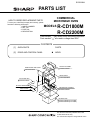
RCD2200M
SERVICE MANUAL
S2801RCD22MP
COMMERCIAL MICROWAVE OVEN
MODELS
R-CD1800M
R-CD2200M
In the interest of user-safety the oven should be restored to its original condition and only parts identical to those
specified should be used.
WARNING TO SERVICE PERSONNEL: Microwave ovens contain circuitry capable of producing very high
voltage and current, contact with following parts may result in a severe, possibly fatal, electrical shock. (High
Voltage Capacitor, High Voltage Power Transformer, Magnetron, High Voltage Rectifier Assembly, High
Voltage Harness etc..)
CONTENTS
PRECAUTIONS TO BE OBSERVED BEFORE AND
DURING SERVICING TO AVOID POSSIBLE EXPOSURE TO EXCESSIVE MICROWAVE ENERGY
CHAPTER 1. WARNING TO SERVICE PERSONNEL
CHAPTER 2. MICROWAVE MEASUREMENT PROCEDURE
CHAPTER 7. TEST PROCEDURES
CHAPTER 8. TOUCH CONTROL PANEL ASSEMBLY
CHAPTER 9. PRECAUTIONS FOR USING LEADFREE SOLDER
CHAPTER 3. FOREWORD AND WARNING
CHAPTER 10. COMPONENT REPLACEMENT AND
ADJUSTMENT PROCEDURE
CHAPTER 4. PRODUCT DESCRIPTION
CHAPTER 11. CIRCUIT DIAGRAMS
CHAPTER 5. OPERATION
Parts List
CHAPTER 6. TROUBLESHOOTING GUIDE
This document has been published to be used for
after sales service only.
The contents are subject to change without notice.
CONTENTS
PRECAUTIONS TO BE OBSERVED BEFORE
AND DURING SERVICING TO AVOID POSSIBLE
EXPOSURE TO EXCESSIVE MICROWAVE ENERGY
CHAPTER 1. WARNING TO SERVICE PERSONNEL
[1] Before Servicing.......................................... 1-1
[2] When the testing is completed,................... 1-1
[3] After repairing.............................................. 1-1
CHAPTER 2. MICROWAVE MEASUREMENT
PROCEDURE
CHAPTER 3. FOREWORD AND WARNING
CHAPTER 4. PRODUCT DESCRIPTION
[1] SPECIFICATIONS ...................................... 4-1
[2] GROUNDING INSTRUCTIONS.................. 4-1
[3] OVEN DIAGRAM ........................................ 4-2
CHAPTER 5. OPERATION
[1] DESCRIPTION OF OPERATING SEQUENCE .................................................... 5-1
[2] OVEN SCHEMATIC .................................... 5-2
[3] DESCRIPTION AND FUNCTION OF
COMPONENTS .......................................... 5-3
CHAPTER 6. TROUBLESHOOTING GUIDE
CHAPTER 7. TEST PROCEDURES
[1] A: MAGNETRON ASSEMBLY TEST .......... 7-1
[2] B: POWER TRANSFORMER TEST ........... 7-1
[3] C: HIGH VOLTAGE RECTIFIER (1)
AND/OR (2) TEST ...................................... 7-1
[4] D: HIGH VOLTAGE CAPACITOR (1)
AND/OR (2) TEST ...................................... 7-2
[5] E: SECONDARY INTERLOCK SWITCH
(1) AND/OR (2) TEST ................................. 7-2
[6] F: PRIMARY INTERLOCK SYSTEM
TEST........................................................... 7-2
[7] G: MONITOR SWITCH (1) AND/OR (2)
TEST........................................................... 7-3
[8] H: BLOWN MINITOR FUSE TEST ............. 7-3
[9] I: FUSE 12A (1) (2) TEST ........................... 7-3
[10] J: TEMPERATURE FUSE TEST ................ 7-4
[11] K: MAGNETRON THERMISTOR TEST..... 7-4
[12] L: EXHAUST THERMISTOR TEST ............ 7-4
[13] M: NOISE FILTER TEST ............................ 7-5
[14] N: KEY UNIT TEST..................................... 7-5
[15] O: CONTROL UNIT TEST .......................... 7-6
[16] P: POWER UNIT TEST .............................. 7-6
[17] Q: RELAY UNIT TEST ................................ 7-6
[18] R: ANTENNA SENSOR TEST.................... 7-7
[19] S: MICROWAVE SENSOR TEST ............... 7-7
CHAPTER 8. TOUCH CONTROL PANEL ASSEMBLY
[1] SPECIAL FUNCTION FOR SERVICING..... 8-1
[2] SERVICING FOR BRINTED WIRING
BOARDS..................................................... 8-6
CHAPTER 9. PRECAUTIONS FOR USING LEADFREE SOLDER
CHAPTER 10. COMPONENT REPLACEMENT
AND ADJUSTMENT PROCEDURE
[1] WARNINGS .............................................. 10-1
[2] OUTER CASE AND REAR COVER REMOVAL...................................................... 10-1
[3] POWER TRANSFORMERS (1) AND/
OR (2) REMOVAL ..................................... 10-2
[4] MAGNETRONS (1) AND/OR (2) REMOVAL...................................................... 10-2
[5] MAGNETRON THERMISTOR ASSEMBLY REPLACEMENT ............................... 10-2
[6] HIGH VOLTAGE CAPACITOR AND
HIGH VOLTAGE RECTIFIER ASSEMBLY REMOVAL ......................................... 10-2
[7] POWER SUPPLY CORD REPLACEMENT........................................................ 10-3
[8] HOW TO RELEASE THE POSITIVE
LOCK CONNECTOR. ............................... 10-3
[9] EXHAUST FAN REMOVAL....................... 10-4
[10] FAN MOTORS REMOVAL ........................ 10-4
[11] ANTENNA MOTORS (UPPER AND
LOWER) REMOVAL ................................. 10-4
[12] POWER UNIT REMOVAL......................... 10-4
[13] RELAY UNIT REMOVAL........................... 10-4
[14] CONTROL PANEL ASSEMBLY AND
CONTROL UNIT REMOVAL..................... 10-4
[15] DOOR SENSING SWITCH/SECONDARY INTERLOCK SWITCHES (1), (2)
AND MONITOR SWITCHES (1), (2) REPLACEMENT ............................................ 10-5
[16] DOOR SENSING SWITCH/SECONDARY INTERLOCK SWITCHES (1), (2)
AND MONITOR SWITCHES (1), (2) ADJUSTMENT............................................... 10-5
[17] DOOR REPLACEMENT ........................... 10-6
[18] DOOR DISASSEMBLY ............................. 10-7
CHAPTER 11. CIRCUIT DIAGRAMS
[1] Figure S-1. Pictorial Diagram .....................11-1
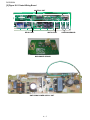
[2] Figure S-2. Switching Power Supply Unit
Circuit.........................................................11-4
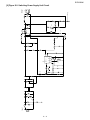
[3] Figure S-3. Relay Unit Circuit ....................11-5
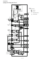
[4] Figure S-4. Control Unit/ Antenna sensor/ Microwave Sensor Circuit ...................11-6
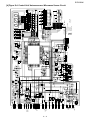
[5] Figure S-5. Printed Wiring Board ...............11-7
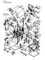
Parts List
RCD2200M
RCD2200M
Service
PRECAUTIONS TO BE OBSERVED BEFORE
AND Manual
DURING SERVICING TO AVOID
POSSIBLE EXPOSURE TO EXCESSIVE MICROWAVE ENERGY
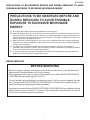
PRECAUTIONS TO BE OBSERVED BEFORE AND
DURING SERVICING TO AVOID POSSIBLE
EXPOSURE TO EXCESSIVE MICROWAVE
ENERGY
(a) Do not operate or allow the oven to be operated with the door open.
(b) Make the following safety checks on all ovens to be serviced before activating the magnetron or other
microwave source, and make repairs as necessary: (1) interlock operation, (2) proper door closing, (3)
seal and sealing surfaces (arcing, wear, and other damage), (4) damage to or loosening of hinges and
latches, (5) evidence of dropping or abuse.
(c) Before turning on microwave power for any service test or inspection within the microwave generating
compartments, check the magnetron, wave guide or transmission line, and cavity for proper alignment,
integrity, and connections.
(d) Any defective or misadjusted components in the interlock, monitor, door seal, and microwave
generation and transmission systems shall be repaired, replaced, or adjusted by procedures described
in this manual before the oven is released to the owner
.
(e) A microwave leakage check to verify compliance with the Federal Performance Standard should be
performed on each oven prior to release to the owner.
BEFOR SERVICING
BEFORE SERVICING
Before servicing an operative unit, perform a microwave emission check as per the Microwave
Measurement Procedure outlined in this service manual.
If microwave emissions level is in excess of the specified limit, contact SHARP ELECTRONICS
CORPORATION immediately @1-800-237-4277.
If the unit operates with the door open, service person should 1) tell the user not to operate the oven
and 2) contact SHARP ELECTRONICS CORPORATION and Food and Drug Administration's
Center for Devices and Radiological Health immediately.
Service personnel should inform SHARP ELECTRONICS CORPORATION of any certified unit found
with emissions in excess of 4mW/cm2. The owner of the unit should be instructed not to use the unit
until the oven has been brought into compliance.
i
RCD2200M
Service Manual
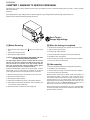
CHAPTER 1. WARNING TO SERVICE PERSONNEL
RCD2200M
Microwave ovens contain circuitry capable of producing very high voltage and current, contact with following parts may result in a severe, possibly
fatal, electrical shock.
(Example)
High Voltage Capacitor, High Voltage Power Transformer, Magnetron, High Voltage Rectifier Assembly, High Voltage Harness etc..
Read the Service Manual carefully and follow all instructions.
Don't Touch !
Danger High Voltage
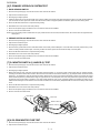
[2] When the testing is completed,
[1] Before Servicing
1. Disconnect the power supply cord, and then remove outer case.
1. Disconnect the power supply cord
case.
, and then remove outer
2. Open the door and block it open.
3. Discharge high voltage capacitor.
2. Open the door and block it open.
4. Reconnect the leads to the primary of the power transformer.
3. Discharge high voltage capacitor.
5. Reinstall the outer case (cabinet).
WARNING: RISK OF ELECTRIC SHOCK. DISCHARGE THE HIGHVOLTAGE CAPACITOR BEFORE SERVICING.
6. Reconnect the power supply cord after the outer case is installed.
The high-voltage capacitor remains charged about 60 seconds
after the oven has been switched off. Wait for 60 seconds and
then short-circuit the connection of the high-voltage capacitor
(that is the connecting lead of the high-voltage rectifier) against
the chassis with the use of an insulated screwdriver.
7. Run the oven and check all functions.
Whenever troubleshooting is performed the power supply must be
disconnected. It may, in some cases, be necessary to connect the
power supply after the outer case has been removed, in this event,
2. Reinstall the outer case (cabinet).
[3] After repairing
1. Reconnect all leads removed from components during testing.
3. Reconnect the power supply cord after the outer case is installed.
4. Run the oven and check all functions.
1) Disconnect the power supply cord, and then remove outer case.
Microwave ovens should not be run empty. To test for the presence of
microwave energy within a cavity, place a cup of cold water on the
oven turntable, close the door and set the power to HIGH and set the
microwave timer for two (2) minutes. When the two minutes has
elapsed (timer at zero) carefully check that the water is now hot. If the
water remains cold carry out Before Servicing procedure and reexamine the connections to the component being tested.
2) Open the door and block it open.
3) Discharge high voltage capacitor.
4) 4.Disconnect the leads to the primary of the power transformer.
5) Ensure that the leads remain isolated from other components and
oven chassis by using insulation tape.
When all service work is completed and the oven is fully assembled,
the microwave power output should be checked and microwave leakage test should be carried out.
6) After that procedure, reconnect the power supply cord.
1–1
RCD2200M
Service
Manual
CHAPTER 2. MICROWAVE MEASUREMENT
PROCEDURE
RCD2200M
A. Requirements:
1) Microwave leakage limit (Power density limit): The power density of microwave radiation emitted by a microwave oven should not exceed 1mW/
cm2 at any point 5cm or more from the external surface of the oven, measured prior to acquisition by a purchaser, and thereafter (through the useful life of the oven), 5 mW/cm2 at any point 5cm or more from the external surface of the oven.
2) Safety interlock switches: Primary interlock relay and door sensing switch shall prevent microwave radiation emission in excess of the requirement
as above mentioned, secondary interlock switch shall prevent microwave radiation emission in excess of 5 mW/cm2 at any point 5cm or more from
the external surface of the oven.
B. Preparation for testing:
Before beginning the actual measurement of leakage, proceed as follows:
1) Make sure that the actual instrument is operating normally as specified in its instruction booklet.
Important:
Survey instruments that comply with the requirement for instrumentation as prescribed by the performance standard for microwave ovens, 21 CFR
1030.10(c)(3)(i), must be used for testing.
2) Place the oven tray in the oven cavity.
3) Place the load of 275±5 ml (9.8 oz) of tap water initially at 20±5°C (68°F) in the center of the oven cavity.
The water container shall be a low form of 600 ml (20 oz) beaker with an inside diameter of approx. 8.5 cm (3-1/2 in.) and made of an electrically
nonconductive material such as glass or plastic.
The placing of this standard load in the oven is important not only to protect the oven, but also to insure that any leakage is measured accurately.
4) Set the cooking control on Full Power Cooking Mode
5) Close the door and select a cook cycle of several minutes. If the water begins to boil before the survey is completed, replace it with 275 ml of cool
water.
C. Leakage test:
Closed-door leakage test (microwave measurement)
1) Grasp the probe of the survey instrument and hold it perpendicular to the gap between the door and the body of the oven.
2) Move the probe slowly, not faster than 1 in./sec. (2.5 cm/sec.) along the gap, watching for the maximum indication on the meter.
3) Check for leakage at the door screen, sheet metal seams and other accessible positions where the continuity of the metal has been breached (eg.,
around the switches, indicator, and vents).
While testing for leakage around the door pull the door away from the front of the oven as far as is permitted by the closed latch assembly.
4) Measure carefully at the point of highest leakage and make sure that the highest leakage is no greater than 4mW/cm2, and that the secondary
interlock switch and the primary interlock relay do turn the oven OFF before any door movement.
NOTE: After servicing, record data on service invoice and microwave leakage report.
2–1
RCD2200M
CHAPTER 3. FOREWORD AND WARNINGService
RCD2200M
Manual
FOREWORD
This Manual has been prepared to provide Sharp Electronics Corp. Service Personnel with Operation and Service Information for the SHARP
MICROWAVE OVENS, R-CD2200M and R-CD1800M.
It is recommended that service personnel carefully study the entire text of this manual so that they will be qualified to render satisfactory customer
service.
Check the interlock switches and the door seal carefully. Special attention should be given to avoid electrical shock and microwave radiation hazard.
WARNING
Never operate the oven until the following points are ensured.
(A) The door is tightly closed.
(B) The door brackets and hinges are not defective.
(C) The door packing is not damaged.
(D) The door is not deformed or warped.
(E) There is not any other visible damage with the oven.
Servicing and repair work must be carried out only by trained service personnel.
DANGER
Certain initial parts are intentionally not grounded and present a risk of electrical shock only during servicing. Service personnel - Do not
contact the following parts while the appliance is energized;
High Voltage Capacitor, Power Transformer, Magnetron, High Voltage Rectifier Assembly, High Voltage Harness;
If provided, Vent Hood, Fan assembly, Cooling Fan Motor.
All the parts marked “
“ on parts list are used at voltages more than 250V.
Removal of the outer wrap gives access to voltage above 250V.
All the parts marked “*“ on parts list may cause undue microwave exposure, by themselves, or when they are damaged, loosened or removed.
3–1
RCD2200M
CHAPTER 4. PRODUCT DESCRIPTION
RCD2200M
Service Manual
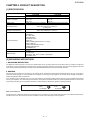
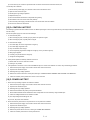
[1] SPECIFICATIONS
ITEM
Power Requirements
Power Consumption
Power Output
Outside Dimensions
Cooking Cavity Dimensions
Control Complement
Weight
Safety Standard
DESCRIPTION
R-CD1800M
R-CD2200M
Single phase 230/208V, 60Hz, A.C. only
3.2kW
2.7kW
230V-14A
230V-12.3A
208V-16A
208V-13.5A
1800W Operating frequency 2450 MHz 2200W Operating frequency 2450 MHz
17-1/2” (W) x 20-1/2” (D) x 13-5/8” (H)
445mm (W) x 520mm (D) x 346mm (H)
(including feet)
14” (W) x 13” (D) x 7-1/8” (H)
355mm (W) x 326mm (D) x 177mm (H)
Touch Control System
Digital Display
Ten number Pads
STOP/CLEAR pad
CUSTOM HELP pad
START pad
SELECT POWER pad (Power level: 0 to 100%)
SELECT TIME pad
DOUBLE/ TRIPLE QUANTITY pad
EXPRESS DEFROST pad
SET MEMORY pad
Approx. 70 lbs/ 32 kg
UL Listed.
FCC Authorized
DHHS Rules, CFR, Title 21, Chapter 1, Subchapter J
NSF Certified, CSA
[2] GROUNDING INSTRUCTIONS
1. GROUNDING INSTRUCTIONS
This appliance must be grounded. In the event of an electrical short circuit, grounding reduces the risk of electric shock by providing an escape wire
for the electric current. This appliance is equipped with a cord having a grounding wire with a grounding plug. The plug must be plugged into an outlet
that is properly installed and grounded in accordance with the National Electrical Code and local codes and ordinances.
2. WARNING
Improper use of the grounding plug can result in a risk of electric shock. The electrical requirements are 230/208 Volt, 60 Hz, AC only, and 20 Amp or
more fused electrical supply. It is recommended that a separate circuit serving only this appliance be provided. When installing this appliance,
observe all applicable codes and ordinances.
If it is necessary to use an extension cord, use only a 3-wire extension cord that has a 3-blade grounding plug and a 3-slot receptacle that will accept
the plug on the appliance. The marked rating of the extension cord should be AC230/208 Volt 20 Amp. Consult a qualified electrician or serviceman if
the grounding instructions are not completely understood or if doubt exists as to whether the appliance is properly grounded.
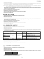
Plug Conguration
NEMA
6-20P
R-CD2200M
NEMA
6-15P
R-CD1800M
Radio or TV Interference
Should there be any interference caused by the microwave oven to your radio or TV, check that the microwave oven is on a different electrical circuit,
relocate the radio or TV as far away from the oven as feasible or check position and signal of receiving antenna.
4–1
RCD2200M
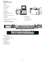
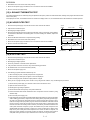
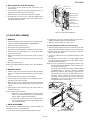
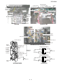
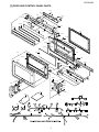
[3] OVEN DIAGRAM
1. OVEN
1. Touch control panels
14
2. Door latch openings
1
10
3. Ceramic shelf
9
4. Splash cover
1
5. Oven light
12
6. Air intake filter
2
7. Air intake openings
4 18 3
5
11
7
15
13
8. Door seals and sealing surfaces
9. Door hinges
10. Oven door with see-through window
17
16
6
8
11. Door latches
15. Power supply cord
12. Door handle
16. Mounting plate
13. Service window for replacing the oven light bulb
17. Screw for mounting plate
14. Ventilation openings
18. Oven ceiling cover
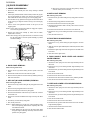
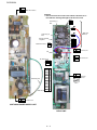
2. TOUCH CONTROL PANEL
1
2
7
7
5
1. SELECT TIME pad
2. SELECT POWER pad
3. DOUBLE/TRIPLE QUANTITY pad
4. CUSTOM HELP pad
5. STOP/CLEAR pad
6. START pad
7. Ten number pads
8. EXPRESS DEFROST pad
9. SET MEMORY pad
4–2
6
3
4
8
9
5
6
RCD2200M
CHAPTER 5. OPERATION
RCD2200M
Service Manual
[1] DESCRIPTION OF OPERATING SEQUENCE
The following is a description of component functions during oven operation.
1. OFF CONDITION
2. The shut-off relay (RY-4) contacts close completing circuits to turn
on the oven lamp and antenna motors.
(For details, refer to Figure O-1)
3. If the door remains open, 60 seconds later the control unit de-energizes shut-off relay (RY-4) turning off the oven lamp and antenna
motors.
Closing the door activates the door sensing switch and secondary
interlock switches (1), (2). (In this condition, the monitor switches (1) &
(2) contacts are opened.) When the oven is plugged in, and the rated
voltage is supplied to the switching power supply unit through the
noise filter, (figure O-1). The switching supply unit supplies D.C. voltage (approx. 24V) to the relay unit. And the display will show “ . “.
4. VARIABLE POWER COOKING
When Variable Cooking Power is programmed, the rated voltage A.C.
is supplied to the power transformer intermittently through the contacts
of relay (RY-2, RY-3). Relays RY-2 and RY-3 are operated by the control unit within an interval 48 second time base. Microwave power
operation is as follows:
2. COOKING CONDITION
(For details, refer to Figure O-2)
Press SELECT TIME pad. Enter cooking time by pressing the number
pads. Press the SELECT POWER pad. Enter power level by pressing
the number pad. When the START pad is pressed, the following operations occur:
VARI-MODE
100%
90%
80%
70%
60%
50%
40%
30%
20%
10%
0%
1. The contacts of relays are closed. And the oven lamp and the
antenna motors connected to the relays are turned on (For details,
refer to Figure O-2).
2. D.C. voltage is supplied to the fan motors, exhaust fan and exhaust
motor from the control unit.
3. Rated voltage is supplied to the primary winding of the power transformer and is converted to about 3.17 volts output on the filament
winding, and approximately 2240 volts on the high voltage winding.
4. The filament winding voltage heats the magnetron filament and the
H.V. winding voltage is sent to a voltage doubler circuit.
ON TIME
48 sec.
44 sec.
40 sec.
36 sec.
32 sec.
26 sec.
22 sec.
16 sec.
12 sec.
8 sec.
0 sec.
OFF TIME
0 sec.
4 sec.
8 sec.
12 sec.
16 sec.
22 sec.
26 sec.
32 sec.
36 sec.
40 sec.
48 sec.
NOTE: The ON/OFF time ratio does not exactly correspond with
the percentage of microwave power, because approx. 3
seconds are needed for heating of the magnetron filament.
5. The microwave energy produced by the magnetron is channelled
through the waveguide into the cavity feed-box, and then into the
cavity where the food is placed to be cooked.
6. Upon completion of the cooking time, the oven will revert to the
OFF condition. The fan motors, exhaust fan and the exhaust motor
will operate at least for 1 minute.
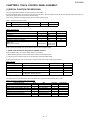
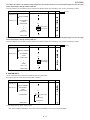
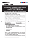
5. TWO MAGNETRON OPERATION SYSTEM
Two magnetrons (1), (2) are equipped in order to get higher microwave power output. The primary windings of the power transformers
(1), (2) are connected so that each magnetron can be oscillated alternatively according to the frequency of the power supply. Refer to the
Figure B-1.
7. When the door is opened during a cook cycle, monitor switches (1)
& (2), door sensing switch, secondary interlock switches (1), (2)
and primary interlock relay are activated with the following results.
The circuits to the high voltage components are de-energized.
OPERATION OF
MAGNETRON
8. The monitor switch (1) is electrically monitoring the operation of the
secondary interlock switch (1) and primary interlock relay, and
monitor switch (2) is electrically monitoring the operation of the secondary interlock switch (2) and primary interlock relay, and monitor
switches (1), (2) are mechanically associated with the door so that
it will function in the following sequence.
COMMERCIAL
FREQUENCY
(60HZ)
POWER OUTPUT
BY MAGNETRON 1
1) (1) When the door opens from a closed position, the contacts of
the primary interlock relay and secondary interlock switches (1),
(2) open. Then the monitor switch contacts close.
POWER OUTPUT
BY MAGNETRON 2
Figure B-1. Operation of Magnetron
2) (2) When the door is closed from the open position, the monitor
switches (1), (2) contacts first open, and then the contacts of the
secondary interlock switches (1), (2) close.
If the secondary interlock switches (1), (2) and primary interlock relay
fail with their contacts closed when the door is opened, the closing of
the monitor switches (1), (2) contacts will form a short circuit through
the monitor fuse, secondary interlock switches (1), (2) and primary
interlock relay, causing the monitor fuse to blow.
3. DOOR OPEN CONDITION
When the door is opened, the contacts of the door sensing switch
open, initiating the following:
1. A signal is input to the control unit energizing the coil of shutoff
relay (RY-4).
5–1
RCD2200M
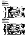
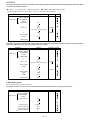
[2] OVEN SCHEMATIC
1. Off Condition
SCHEMATIC
NOTE: CONDITION OF OVEN
1. DOOR CLOSED
2. “ . “ APPEARS ON DISPLAY
Figure O-1. Oven Schematic-Off Condition
2. Cooking Condition
SCHEMATIC
NOTE: CONDITION OF OVEN
1. DOOR CLOSED.
2. SELECT TIME PAD TUCHED..
3. COOKING TIME PROGRAMMED.
4. START PAD TOUCHED.
Figure O-2. Oven Schematic-Cooking Condition
5–2
RCD2200M
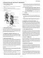
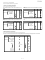
[3] DESCRIPTION AND FUNCTION OF COMPONENTS
1. DOOR OPEN MECHANISM
3. If the door is opened, and the contacts of the primary interlock relay
and secondary interlock switch of the same circuit fail to open, the
monitor fuse blows simultaneously with closing of the monitor
switch contacts of that circuit (1 or 2).
1. The handle lever is pulled.
2. The upper and lower latch heads are lifted up by the linked latch
lever.
CAUTION: BEFORE REPLACING A BLOWN MONITOR FUSE TEST
THE DOOR SENSING SWITCH, PRIMARY INTERLOCK
RELAY, SECONDARY INTERLOCK SWITCHES (1), (2),
DOOR SENSING SWITCH AND MONITOR SWITCHES
(1), (2) FOR PROPER OPERATION. (REFER TO CHAPTER “TEST PROCEDURE”).
3. The latch lever is lifted up by the handle lever.
4. Now both latch heads are lifted up, so they can be released from
the latch hook.
5. Now the door can be opened.
Latch
lever
NOTE: MONITOR FUSE AND SWITCH ARE REPLACED AS AN
ASSEMBLY.
Switch lever A
5. MONITOR FUSE
Latch hook
1. The monitor fuse blows when the contacts (COM-NO) of the primary interlock relay (RY1) and secondary interlock switch remain
closed with the oven door open and when the monitor switch
closes.
Monitor switch (2)
Latch
head
Monitor switch (1)
2. If the wire harness or electrical components are short-circuited, this
monitor fuse blows to prevent an electric shock or fire hazard.
Switch lever B
Secondary
interlock switch (2)
Handle
lever
6. MAGNETRON TEMPERATURE FUSES (1), (2)
Secondary
interlock switch (1)
Latch
head
The temperature fuses (1), (2) located on the top of the upper and
lower waveguide, are designed to prevent damage to the magnetrons
(1), (2). If an over heated condition develops in the tube due to blower
motor failure, obstructed air ducts, dirty or blocked air intake, etc., the
circuit to the magnetrons are interrupted. Under normal operation, the
temperature fuses remains closed. However, when abnormally high
temperatures are generated within the magnetron, the temperature
fuse will open at 302°F (150°C) causing the microwave energy to stop.
The defective temperature fuse must be replaced with new rated one.
Door sensing switch
Switch lever C
Figure D-1. Door Open Mechanism
2. DOOR SENSING SWITCH
The door sensing switch is activated by the latch head of the door and
switch lever C. When the door is opened, the contacts of the switch
open and interrupt the circuit to the coils of the primary interlock relay.
The contacts of the primary relay then open and interrupt the circuit to
the primary winding of the power transformers.
7. OVEN TEMPERATURE FUSE
The temperature fuse, located on the side of the exhaust duct assembly, is designed to prevent damage to the oven by fire. If the food load
is overcooked, by either error in cook time or defect in the control unit,
the temperature fuse will open. Under normal operation, the oven temperature fuse remains closed. However, when abnormally high temperatures are generated within the oven cavity, the oven temperature
fuse will open at 248°F (120°C), causing the oven to shut down. The
defective temperature fuse must be replaced with new rated one.
3. SECONDARY INTERLOCK SWITCHES (1), (2)
The secondary interlock switches (1), (2) are activated by the upper
latch head of the door and switch lever B. When the door is opened,
the contacts of the switch open and interrupt the circuit to the primary
winding of the power transformers (1), (2).
8. EXHAUST THERMISTOR
4. MONITOR SWITCHES (1), (2)
The exhaust thermistor is located on the side of the exhaust duct
assembly. The temperature in the exhaust duct is detected through the
resistance of the thermistor. If the temperature is high, the control
panel will display”EE7” and the oven will stop to avoid overheating and
catching fire. If the thermistor is open, the control panel will display
“EE8” and the oven will stop.
The monitor switches (1), (2) are mounted in the upper position of the
latch hook. The monitor switches are activated by the upper latch head
of the door and switch lever A. When the door is opened, the contacts
of the monitor switches close. Monitor switch (1) is intended to render
the oven inoperative by means of blowing the monitor fuse, when the
contacts of the primary interlock relay and secondary interlock switch
(1) fail to open when the door is opened. Monitor switch (2) is intended
to render the oven inoperative by means of blowing the monitor fuse,
when the contacts of the primary interlock relay and secondary interlock switch (2) fail to open when the door is opened.
9. MAGNETRON THERMISTOR
The thermistor is a negative temperature coefficient type. The air temperature around the upper and lower magnetrons is detected through
the resistance of the thermistor. If the temperature is high, the control
panel will display “EE7” and the oven will stop to protect the magnetrons against overheat. If the magnetron thermistor is open, the control
panel will display “EE8” and the oven will stop.
Functions:
With the door shut, the contacts of the door sensing switch and the
secondary interlock switches (1), (2) are closed and the contacts of the
monitor switches (1), (2) are open.
10. FAN MOTORS
1. When the door is opened, the contact of the door sensing switch
and secondary interlock switches (1), (2) are opened first, then the
contact of the monitor switches (1), (2) are closed.
The fan motors drive blades which draw external cool air into the oven.
This cool air is directed through the air vanes surrounding the magnetrons and cools the magnetrons. This air is channelled through the
oven cavity to remove steam and vapours given off from the heating
foods. It is then exhausted through the exhausting air vents at the
oven cavity.
2. As the door goes to a closed position, the contacts of the monitor
switches (1), (2) are opened first, then the contacts of the door
sensing switch and the secondary interlock switches (1), (2) close.
5–3
RCD2200M
During cooking, they operate. After cooking, they will operate at least
for 1 minute and the maximum operating time is 4 minutes. When the
temperature of the magnetron thermistor becomes bellow 110°C, the
fan motors will stop. These two (2) fan motors are D.C. motors.
4. The large electric currents flow through the high voltage winding of
the high voltage transformer.
11. EXHAUST MOTOR
6. The fuse 12A blows by the large electric currents.
The exhaust motor is located on the side of the exhaust duct assembly. This motor drives a blade in the exhaust duct assembly. The
driven blade draws the external cool air into the oven from the intake
duct assembly. Then it sends the air out of the oven through the
exhaust duct assembly. During cooking, the exhaust motor operates.
After cooking, it will operate at least for 1 minute and the maximum
operating time is 4 minutes. When the temperature of the exhaust
thermistor becomes bellow 65°C, the exhaust motor will stop. This
motor is D.C. motor.
7. The power supplying to the high voltage transformer is cut off.
5. The large electric currents beyond 12A flow through the primary
winding of the high voltage transformer.
18. OVEN LAMP
The oven cavity light illuminates the interior of the oven so that food
being cooked can be examined visually through the door window without having to open the door.
19. NOISE FILTER
The noise filter prevents the radio frequency interference that might
flow back in the power circuit.
NOTE: Do not disconnect the power supply from the exhaust motor
when it is turned on. Or it may be out of order.
12. ANTENNA MOTORS
The upper and lower antenna motors drive antennas to radiate the
microwave.
13. EXHAUST FAN
The exhaust fan is located to the rear cover. It sends the air (which is
at the top of the oven cavity) out of the oven. This motor is D.C. motor.
14. ANTENNA SENSOR
The antenna sensors are located to the top and bottom of the oven
cavity. And they watch if the antennas are rotating or not.
15. MIROWAVE SENSOR
The microwave sensor is located on the top of the oven cavity. And it
watch if the microwave is radiated into the oven cavity or not.
16. FUSE 12A (1) (2)
1. If the wire harness or electrical components are short-circuited, this
fuse blows to prevent an electric shock or fire hazard.
2. The fuse also blows when the asymmetric rectifier, H.V. rectifier,
H.V. wire harness, H.V. capacitor, magnetron or secondary winding
of high voltage transformer is shorted.
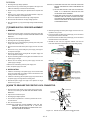
17. H.V. ASYMMETRIC RECTIFIER (1) (2)
The H.V.asymmetric rectifiers (1) (2) are solid state devices that prevent current flow is both directions. And they prevent the temperature
rise of the high voltage transformers (1) (2) by blowing the fuses 12A
(1) (2) when the high voltage rectifiers (1) (2) are shorted. The rated
peak reverse voltage of D1 of the asymmetric rectifier is 6 KV. The
rated peak reverse voltage of D2 of the asymmetric rectifier is 1.7 KV.
D1 and D2 of the asymmetric rectifier or high voltage rectifier are
shorted when the each peak reverse voltage goes beyond the each
rated peak reverse voltage. (The process of the blowing the fuse 12A.)
D2
D1
ASYMMETRIC
RECTIFIER
HIGH VOLTAGE
RECTIFIER
NOTE: The H.V.asymmetric rectifier is assembled with the high voltage rectifier actually.
1. The high voltage rectifier is shorted by some fault when microwave
cooking or dual cooking.
2. The peak reverse voltage of D2 of the rectifier goes beyond the
rated peak reverse voltage 1.7 KV in the voltage doubler circuit.
3. D2 of the rectifier is shorted.
5–4
RCD2200M
CHAPTER 6. TROUBLESHOOTING GUIDEService
RCD2200M
Manual
Never touch any part in the circuit with your hand or an uninsulated tool while the power supply is connected.
When troubleshooting the microwave oven, it is helpful to follow the Sequence of Operation in performing the checks. Many of the possible causes of
trouble will require that a specific test be performed. These tests are given a procedure letter which will be found in the “Test Procedure“ section.
IMPORTANT:
If the oven becomes inoperative because of a blown monitor fuse, check the monitor switches (1), (2), primary interlock relay RY1, door sensing
switch and secondary interlock switches (1), (2), before replacing the monitor fuse. If monitor fuse is replaced, the monitor switch (1) and/or (2) must
also be replaced. Use part FFSBA033WRKZ as an assembly.
IMPORTANT:
Whenever troubleshooting is performed with the power supply cord disconnected. It may, in some cases, be necessary to connect the power supply
cord after the outer case has been removed, in this event,
1. Disconnect the power supply cord, and then remove outer case.
2. Open the door and block it open.
3. Discharge two high voltage capacitors.
4. Disconnect the leads to the primaries of the two power transformers.
5. Ensure that the leads remain isolated from other components and oven chassis by using insulation tape.
6. After that procedure, reconnect the power supply cord.
When the testing is completed
1. Disconnect the power supply cord, and then remove outer case.
2. Open the door and block it open.
3. Discharge two high voltage capacitors.
4. Reconnect the all leads removed from components during testing.
5. Reinstall the outer case (cabinet).
6. Reconnect the power supply cord after the outer case is installed.
7. Run the oven and check all functions.
6–1
6–2
COOKING
CONDITION
OFF
CONDITION
CONDITION
Oven goes into a cook cycle but shuts down before and off
cooking cycle.
Oven does not go into cook cycle when START pad is touched.
Low or no power is produced during cooking condition. (The
food is heated incompletely or not heated at all.)
Variable cooking does not operates properly, except HIGH
power functions.
Fan motor does not operate.
Exhaust fan does not operate.
Exhaust motor does not operate.
Oven doen not go into cook cycle when START pad on the
door is touched.
Oven lamp and antenna motors do not go on in cook cycle.
It seems that the output power is lower or higher than
the rated one.
Monitor fuse blows when power cord is plugged into wall
receptacle.
" . " does not appear in display when power cord is first
plugged into wall receptacle.
Oven lamp does not go on for 1 minute after door is opened.
Home fuse blows when power cord is plugged into wall
receptacle
PROBLEM
POSSIBLE CAUSE AND
DEFECTIVE PARTS
J
OVEN TEMPERATURE FUSE
H J
MAGNETRON TEMP. FUSE (1), (2)
F G
MONITOR SWITCH (1), (2)
A B C D E F
I
RELAY UNIT
POWER UNIT
KEY UNITS
MAGNETRON THERMISTOR
NOISE FILTER
EXHAUST THERMISTOR
FUSE 12A (1), (2)
PRIMARY INTERLOCK SYSTEM
MONITOR FUSE
DOOR SENSING SWITCH
SECONDARY INTERLOCK SWITCH (1), (2)
HIGH VOLTAGE CAPACITOR (1), (2)
H.V. RECTIFIER ASSEMBLY (1), (2)
POWER TRANSFORMER (1), (2)
MAGNETRON (1), (2)
L K M N P Q O
CONTROL UNIT
TEST PROCEDURE
RCD2200M
LOW POWER SUPPLY VOLTAGE
NO POWER AT OUTLET
SHORT IN POWER SUPPLY CORD
LOOSE WIRING
AIR FLOW BLOCKED
SWITCH UNIT.
VOLTAGE SELECT RELAY (1), (2)
EXHAUST MOTOR
EXHAUST FAN
FAN MOTORS
OVEN LAMP OR SOCKET
RCD2200M
SPECIFICATION OF ERROR
Outline
When a basic performance and the function are ruined
When the dangers of the state of the high temperature and the ignition, etc. are
foreseen
When you mistake the setting of the heating time
When neither the power supply nor the environmental condition are proper
When informing of the exchange time of parts
EE 1
EE 2
EE 3
EE 4
EE 5
EE 7
EE 8
EE 9
EE 10
EE 11
EE 21
EE 31
EE 81
EE 83
EE 14
EE 24
EE 44
EE 54
EE 15
EE 25
EE 35
EE 16
EE 26
EE 17
EE 27
EE 18
EE 28
EE 38
EE 29
EE 19
EE 39
EE7
Operation stop
Operation stop
Display Only
EE9
EE4, EE5, EE6
CC1, CC2, CC3, CC4
Exceeding of maxmum cooking time
Burned food
Relay unit
Control unit
Antenna sensor (1) (Upper)
Antenna sensor (2) (Lower)
Microwave sensor
Low or High power supply voltage
No load or small load operation
Loose wiring
Q O R R S
Exhaust thermistor
Fan motors
Exhaust motor
Antenna motor 1 and/or 2
Air flow blocked
Content of error
Displaying and heating stop
Primary interlock system
Fuse 12A 1 and/or 2
Magnetron temp. fuse 1 and/or 2
Magnetron thermistor 1 and/or 2
Error history
display
Magnetron 1and /or 2
POSSIBLE CAUSE
AND
DEFECTIVE PARTS
Usual error
display
EE1
EE2
EE3
EE4
EE5
EE7
EE8
EE9
EE8
EE1
EE2
EE3
EE8
EE3
EE0
EE0
EE0
EE0
EE0
EE0
EE0
EE8
EE8
EE7
EE7
EE8
EE8
EE8
EE8
EE6
EE6
Display in operation usually
EE0, EE1, EE2, EE3, EE8
A B D C E F I J K L
Power transformer 1 & 2
High voltage capacitor 1 and /or 2
H.V.rectifier assembly 1 and/or 2
Secondary interlock switch 1 and/or
TEST PROCEDURE
Operation when error occurs
Displaying and heating stop
Failer of high voltage circuit 1
Failer of high voltage circuit 2
Failer of high voltage circuit 1&2
Too high of input voltage(+13%)
Too low of input voltage(-13%)
Food burned (temp., too high)
Melted contacts of relays
Over maximum cooking time
EEPROM error
Life end of magnetron 1
Life end of magnetron 2
Life end of magnetron 1&2
Life end of relays RY2/RY3
Over Current error
MG1 Cooling Fan lock judge
MG2 Cooling Fan lock judge
Exhaust motor lock judge
Life end of exhaust motor
MG1 antenna rotation error
MG2 antenna rotation error
MG1/2 antenna rotation error
MG1 thermistor open
MG2 thermistor open
MG1 temperature, too high
MG2 temperature, too high
Magnetron 1
Magnetron 2
Magnetron 1& 2
Exhaust thermistor open/short
No food
small food
NOTE 1: If the power supply voltage is higher than 230V+13% (259.9V), EE4 will be displayed.
If the power supply voltage is lower than 208V-13% (180.96V), EE5 will be displayed.
NOTE 2: "
" means that the parts should be replaced when EE11, EE21, EE31 or EE81 is indicated on the display.
Display for maintenance
CC1 CC2 CC3 CC4
{
{
{
{
Error history display
–
–
–
–
Content of maintenance
Check item
MG1 exchange time information
MG2 exchange time information
Exhaust Fan motor exchange time information
T/C unit exchange time information
Using time of MG1
Using time of MG2
Using time of Exhaust motor
Using number of times of RY2/RY3
6–3
Parts to be
replaced
MG1
MG2
Exhaust motor
Relay unit
RCD2200M
CHAPTER 7. TEST PROCEDURES
RCD2200M
Service Manual
[1] A: MAGNETRON ASSEMBLY TEST
1. Disconnect the power supply cord, and then remove outer case and rear cover.
2. Open the door and block it open.
3. Discharge high voltage capacitor.
4. To test for an open filament, isolate the magnetron from the high voltage circuit. A continuity check across the magnetron filament leads should
indicate less than 1 ohm.
5. To test for a shorted magnetron, connect the ohmmeter leads between the magnetron filament leads and chassis ground. This test should indicate
an infinite resistance. If there is little or no resistance the magnetron is grounded and must be replaced.
6. Reconnect all leads removed from components during testing.
7. Reinstall the rear cover and the outer case (cabinet).
8. Reconnect the power supply cord after the outer case is installed.
9. Run the oven and check all functions.
1. MICROWAVE OUTPUT POWER
The following test procedure should be carried out with the microwave oven in a fully assembled condition (outer case fitted).
HIGH VOLTAGES ARE PRESENT DURING THE COOK CYCLE, SO EXTREME CAUTION SHOULD BE OBSERVED.
Power output of the magnetron can be measured by performing a water temperature rise test. This test should only be used if above tests do not indicate a faulty magnetron and there is no defect in the following components or wiring: silicon rectifier, high voltage capacitor and power transformer.
This test will require a 16 ounce (453cc) measuring cup and an accurate mercury thermometer or thermocouple type temperature tester. For accurate
results, the following procedure must be followed carefully:
1. Fill the measuring cup with 16 oz. (453cc) of tap water and measure the temperature of the water with a thermometer or thermocouple temperature tester. Stir the thermometer or thermocouple through the water until the temperature stabilizes. Record the temperature of the water.
2. Place the cup of water in the oven. Operate oven at 100% Power selecting more than 60 seconds cook time. Allow the water to heat for 60 seconds, measuring with a stop watch, second hand of a watch or the digital read-out countdown.
3. Remove the cup from the oven and again measure the temperature, making sure to stir the thermometer or thermocouple through the water until
the maximum temperature is recorded.
4. Subtract the cold water temperature from the hot water temperature. The normal result should be 49 to 91.1°F (27.2 to 50.6°C) rise in temperature
for R-CD18MP. The normal result should be 59 to 109.8°F (32.8 to 61°C) rise in temperature for R-CD22MP. If the water temperatures are accurately measured and tested for the required time period the test results will indicate if the magnetron tube has low power output (low rise in water
temperature) which would extend cooking time or high power output (high rise in water temperature) which would reduce cooking time. Because
cooking time can be adjusted to compensate for power output, the magnetron tube assembly should be replaced only if the water temperature rise
test indicates a power output well beyond the normal limits. The test is only accurate if the power supply line voltage is 208/230 volts and the oven
cavity is clean.
.
[2] B: POWER TRANSFORMER TEST
1. Disconnect the power supply cord, and then remove outer case and rear cover.
2. Open the door and block it open.
3. Discharge high voltage capacitor.
4. Disconnect the primary input terminals and measure the resistance of the transformer with an ohmmeter. Check for continuity of the coils with an
ohmmeter. On the R x 1 scale, the resistance of the primary coil should be less than 1 ohm and the resistance of the high voltage coil should be
approximately 58 ohms; the resistance of the filament coil should be less than 1 ohm.
5. Reconnect all leads removed from components during testing.
6. Reinstall the rear cover and the outer case (cabinet).
7. Reconnect the power supply cord after the outer case is installed.
8. Run the oven and check all functions.
(HIGH VOLTAGES ARE PRESENT AT THE HIGH VOLTAGE TERMINAL, SO DO NOT ATTEMPT TO MEASURE THE FILAMENT AND HIGH
VOLTAGE.)
[3] C: HIGH VOLTAGE RECTIFIER (1) AND/OR (2) TEST
1. HIGH VOLTAGE RECTIFIERFTEST
1. Disconnect the power supply cord, and then remove the outer case and the rear cover.
2. Open the door and block it open.
3. Discharge two high voltage capacitors.
7–1
RCD2200M
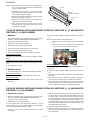
4. Isolate the high voltage rectifier assembly from the HV circuit. The high voltage rectifier can be tested using an ohmmeter set to its highest range.
Connect the ohmmeter across the terminal B+C of the high voltage rectifier and note the reading obtained. Reverse the meter leads and note this
second reading. The normal resistance is infinite in one direction and more than 100k ohms in the other direction.
5. Reconnect all leads removed from components during testing.
6. Reinstall the rear cover and the outer case (cabinet).
7. Reconnect the power supply cord after the rear cover and the outer case are installed.
8. Run the oven and check all functions.
A
D2
B
D1
ASYMMETRIC
RECTIFIER
C
HIGH VOLTAGE
RECTIFIER
2. ASYMMETRIC RECTIFIER TEST
1. Disconnect the power supply cord, and then remove outer case.
2. Open the door and block it open.
3. Discharge two high voltage capacitors.
4. Isolate the high voltage rectifier assembly from the HV circuit. The asymmetric rectifier can be tested using an ohmmeter set to its highest range
across the terminals A+B of the asymmetric rectifier and note the reading obtained. Reverse the meter leads and note this second reading. If an
open circuit is indicated in both directions then the asymmetric rectifier is good. If the asymmetric rectifier is shorted in either direction, then the
asymmetric rectifier is faulty and must be replaced with high voltage rectifier. When the asymmetric rectifier is defective, check whether magnetron, high voltage rectifier, high voltage wire or filament winding of the high voltage transformer is shorted.
5. Reconnect all leads removed from components during testing.
6. Reinstall the rear cover and the outer case (cabinet).
7. Reconnect the power supply cord after the rear cover and the outer case are installed.
8. Run the oven and check all functions.
NOTE: Be sure to use an ohmmeter that will supply a forward bias voltage of more than 6.3 volts.
[4] D: HIGH VOLTAGE CAPACITOR (1) AND/OR (2) TEST
1. Disconnect the power supply cord, and then remove outer case and rear cover.
2. Open the door and block it open.
3. Discharge high voltage capacitor.
4. If the capacitor is open, no high voltage will be available to the magnetron. Disconnect input leads and check for short or open between the terminals using an ohmmeter.
Checking with a high ohm scale, if the high voltage capacitor is normal, the meter will indicate continuity for a short time and should indicate an
open circuit once the capacitor is charged. If the above is not the case, check the capacitor with an ohmmeter to see if it is shorted between either
of the terminals and case. If it is shorted, replace the capacitor.
5. Reconnect all leads removed from components during testing.
6. Reinstall the rear cover and the outer case (cabinet).
7. Reconnect the power supply cord after the rear cover and the outer case are installed.
8. Run the oven and check all functions.
[5] E: SECONDARY INTERLOCK SWITCH (1) AND/OR (2) TEST
1. Disconnect the power supply cord, and then remove outer case and rear cabinet.
2. Open the door and block it open.
3. Discharge high voltage capacitor.
4. Isolate the switch and connect the ohmmeter to the common (COM.) and normally open (NO) terminal of the switch. The meter should indicate an
open circuit with the door open and a closed circuit with the door closed. If improper operation is indicated, replace the secondary interlock switch.
5. Reconnect all leads removed from components during testing.
6. Reinstall the rear cover and the outer case (cabinet).
7. Reconnect the power supply cord after the rear cover and the outer case are installed.
8. Run the oven and check all functions.
7–2
RCD2200M
[6] F: PRIMARY INTERLOCK SYSTEM TEST
1. DOOR SENSING SWITCH
1. Disconnect the power supply cord, and then remove outer case and rear cabinet.
2. Open the door and block it open.
3. Discharge high voltage capacitor.
4. Isolate the switch and connect the ohmmeter to the common (COM.) and normally open (NO) terminal of the switch. The meter should indicate an
open circuit with the door open and a closed circuit with the door closed. If improper operation is indicated, replace the door sensing switch.
5. Reconnect all leads removed from components during testing.
6. Reinstall the rear cover and the outer case (cabinet).
7. Reconnect the power supply cord after the rear cover and the outer case are installed.
8. Run the oven and check all functions.
NOTE: If the door sensing switch contacts fail in the open position and the door is closed, the blower motor, stirrer motors and oven light will be activated by RY1.
2. PRIMARY INTERLOCK RELAY RY1
1. Disconnect the power supply cord, and then remove outer case and rear cabinet.
2. Open the door and block it open.
3. Discharge high voltage capacitor.
4. Disconnect two (2) wire leads from the male tab terminals of the Primary Interlock Relay RY1. Check the state of the relay contacts using a ohmmeter. The relay contacts should be open. If the relay contacts are closed, replace the circuit board entirely or the relay itself.
5. Reconnect all leads removed from components during testing.
6. Reinstall the rear cover and the outer case (cabinet).
7. Reconnect the power supply cord after the rear cover and the outer case are installed.
8. Run the oven and check all functions.
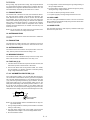
[7] G: MONITOR SWITCH (1) AND/OR (2) TEST
1. Disconnect the power supply cord, and then remove outer case and rear cabinet.
2. Open the door and block it open.
3. Discharge high voltage capacitor.
4. Before performing this test, make sure that the secondary interlock switches (1), (2) and the primary interlock relay RY1 are operating properly,
according to the above Switch Test Procedure. Disconnect the wire lead from the monitor switches (1), (2) (COM) terminals. Check the monitor
switches (1), (2) operation by using the ohmmeter as follows. When the door is open, the meter should indicate a closed circuit. When the monitor
switch actuator is pushed by a screw driver through the upper latch hole on the front plate of the oven cavity with the door opened (in this condition
the plunger of the monitor switch is pushed in), the meter should indicate an open circuit. If improper operation is indicated, the switch may be
defective. After testing the monitor switches, reconnect the wire lead to the monitor switch (COM) terminals and check the continuity of the monitor
circuit.
5. Reconnect all leads removed from components during testing.
6. Reinstall the rear cover and the outer case (cabinet).
7. Reconnect the power supply cord after the rear cover and the outer case are installed.
8. Run the oven and check all functions.
Screw Driver
Latch hook
Monitor switch (2)
Monitor switch (1)
Ohmmeter
[8] H: BLOWN MINITOR FUSE TEST
1. Disconnect the power supply cord, and then remove outer case and rear cabinet.
2. Open the door and block it open.
7–3
RCD2200M
3. Discharge high voltage capacitor.
4. If the monitor fuse is blown when the door is opened, check the primary interlock relay RY1, secondary interlock switches (1), (2) and monitor
switches (1), (2) according to the “TEST PROCEDURE” for those switches before replacing the blown monitor fuse.
CAUTION: CAUTION: BEFORE REPLACING A BLOWN MONITOR FUSE, TEST THE PRIMARY INTERLOCK RELAY, SECONDARY INTERLOCK
SWITCHES, DOOR SENSING SWITCH AND MONITOR SWITCHES FOR PROPER OPERATION.
If the monitor fuse is blown by improper switch operation, the monitor fuse and monitor switch must be replaced with “monitor fuse and monitor
switch assembly” part number FFS-BA033WRKZ, even if the monitor switch operates normally. The monitor fuse and monitor switch assembly is
comprised of a 20 ampere fuse and switch.
5. Reconnect all leads removed from components during testing.
6. Reinstall the rear cover and the outer case (cabinet).
7. Reconnect the power supply cord after the rear cover and the outer case are installed.
8. Run the oven and check all functions.
[9] I: FUSE 12A (1) (2) TEST
1. Disconnect the power supply cord, and then remove outer case and rear cabinet.
2. Open the door and block it open.
3. Discharge high voltage capacitor.
4. If the fuse is blown, check the magnetron, high voltage capacitor, high voltage rectifier assembly, according to the “TEST PROCEDURE” before
replacing the blown fuse. Then replace the fuse.
5. Reconnect all leads removed from components during testing.
6. Reinstall the rear cover and the outer case (cabinet).
7. Reconnect the power supply cord after the rear cover and the outer case are installed.
8. Run the oven and check all functions.
[10] J: TEMPERATURE FUSE TEST
1. Disconnect the power supply cord, and then remove outer case and rear cabinet.
2. Open the door and block it open.
3. Discharge high voltage capacitor.
4. A continuity check across the temperature fuse terminals should indicate a closed circuit unless the temperature of the temperature fuse reaches
specified temperature as shown below.
Open temperature
Magnetron temperature
fuse (1)
Magnetron temperature
fuse (2)
Magnetron temperature
fuse (1), (2)
150°C
Oven temperature fuse
120°C
Close temperature
Display or
Condition
EE1
Non resetable type
EE2
EE3
Non resetable type
Oven shut off
Check point
Magnetron (1) Failure:
Test magnetron (1) and fan motor.
Magnetron (2) Failure:
Test magnetron (2) and fan motor.
Magnetron (1), (2) Failure: Test magnetron (1), (2).
Check fan motor and ventilation opening.
Food has been burned in oven.
Temperature of oven inside is very high.
5. Reconnect all leads removed from components during testing.
6. Reinstall the rear cover and the outer case (cabinet).
7. Reconnect the power supply cord after the rear cover and the outer case are installed.
8. Run the oven and check all functions.
CAUTION: IF THE TEMPERATURE FUSE INDICATES AN OPEN CIRCUIT AT ROOM TEMPERATURE, REPLACE TEMPERATURE FUSE.
[11] K: MAGNETRON THERMISTOR TEST
1. Disconnect the power supply cord, and then remove outer case and rear cabinet.
2. Open the door and block it open.
3. Discharge high voltage capacitor.
4. Disconnect the connector of the magnetron thermistor from the harness. Measure the resistance of the thermistor with an ohmmeter. Connect the
ohmmeter leads to the connector of the thermistor.
Room temperature
68°F (20°C)
Resistance
Approx. 750KΩ
If the meter does not indicate above resistance, replace the thermistor.
5. Reconnect all leads removed from components during testing.
7–4
RCD2200M
6. Reinstall the rear cover and the outer case (cabinet).
7. Reconnect the power supply cord after the rear cover and the outer case are installed.
8. Run the oven and check all functions.
[12] L: EXHAUST THERMISTOR TEST
The exhaust thermistor can be checked by using the Special function (SF-6). Check the exhaust thermistor, referring to the pages of the Exhaust thermistor check (SF-6).
If the display shows “OH”, the exhaust thermistor is normal. If the display shows “no”, the exhaust thermistor is abnormal and it should be replaced.
[13] M: NOISE FILTER TEST
1. Disconnect the power supply cord, and then remove outer case and rear cabinet.
2. Open the door and block it open.
Source
(White)
Source
(Black)
NOISE FILTER
DISCHARGE RESISTOR
470K 1/2W
3. Discharge high voltage capacitor.
4. Disconnect the lead wires from the terminal the noise filter. Using an ohmmeter, check between
the terminals as described in the following table. If incorrect reading are obtained, replace the
noise filter.
LINE CROSS CAPACITOR
1.0μF / AC 250V
FUSE
20A
NOISE SUPPRESSION COIL
5. Reconnect all leads removed from components during testing.
6. Reinstall the rear cover and the outer case (cabinet).
7. Reconnect the power supply cord after the rear cover and the outer case are installed.
8. Run the oven and check all functions.
MEASURING POINT
Between source terminals
Between source (Black) and load (Black) terminals
Between source (White) and load (White/Brown) terminals
INDICATION OF OHMMETER
Approx. 470KΩ
Short circuit.
Short circuit.
LINE BYPASS
CAPACITOR
0.0033μF / AC 125V
LINE BYPASS
CAPACITOR
0.0033μF / AC 125V
Load
(White/Brown)
Load
(Black)
[14] N: KEY UNIT TEST
1. Disconnect the power supply cord, and then remove outer case and rear cabinet.
2. Open the door and block it open.
3. Discharge high voltage capacitor.
4. Check Key unit ribbon connection before replacement.
5. If key unit ribbon connection is normal, carry out the following procedures.
6. Re-install the rear cover and the outer case (cabinet).
7. Reconnect the power supply cord.
8. The following symptoms indicate a defective key unit.
1) When touching the pads, a certain pad produces no signal at all.
2) When touching a number pad, two figures or more are displayed.
3) When touching the pads, sometimes a pad produces no signal.
9. When you can not judge if the key unit is normal or not by using the item 8 above, carry out following test procedures.
1) Disconnect the power supply cord, and then remove outer case and rear cover.
2) Open the door and block it open.
5
3) Discharge two high voltage capacitors.
4
3
X2/X3
EXPRESS
DEFROST
2
1
CN-M
SELECT
TIME
SELECT
POWER
6
4) Disconnect the leads to the primary of the power transformer.
1
4
3
2
8
8
5
6
7
9
9
0
STOP
CLEAR
7
5) Ensure that these leads remain isolated from other components and oven chassis by using
insulation tape.
SET
CUSTOM
MEMORY
HELP
6) Reconnect the power supply cord.
START
< KEY UNIT >
7) If the display fails to clear when the STOP/CLEAR pad is depressed, first verify the flat ribbon
cable is making good contact, verify that the door sensing switch (stop switch) operates properly; that is the contacts are closed when the door is closed and open when the door is open.
If the door sensing switch (stop switch) is good, disconnect the flat ribbon cable that connects
the key unit to the control unit and make sure the door sensing switch is closed (either close
the door or short the door sensing switch connector). Use the Key unit matrix indicated on the
control panel schematic and place a jumper wire between the pins that correspond to the
STOP/CLEAR pad making momentary contact. If the control unit responds by clearing with a
beep the key unit is faulty and must be replaced. If the control unit does not respond, it is
faulty and must be replaced. If a specific pad does not respond, the above method may be
used (after clearing the control unit) to determine if the control unit or key pad is at fault.
7–5
CN-Z
1
1
1
2
2
2
3
3
3
4
4
4
5
5
5
1
4
3
6
6
6
8
5
6
7
7
7
7
9
0
STOP
CLEAR
START
CN-Q
8
CN-R
< SW UNIT >
2
< DOOR KEY UNIT >
RCD2200M
8) For the door key unit, check the open/short and/or connection of the switch unit and the harness, too.
10.If the Key unit is defective.
1) Disconnect the power supply cord, and then remove outer case and rear cover.
2) Open the door and block it open.
3) Discharge two high voltage capacitors.
4) Replace the Key unit.
5) Reconnect all leads removed from components during testing.
6) Re-install the rear cover and the outer case (cabinet).
7) Reconnect the power supply cord after the rear cover and the outer case are installed.
8) Run the oven and check all functions.
[15] O: CONTROL UNIT TEST
The following symptoms indicate a defective control unit. Before replacing the control unit, perform the Key units test (Procedure) to determine if control unit is faulty.
Connect the power supply cord. And check for followings.
1. In connection with pads.
1) When touching the pads, a certain group of pads do not produce a signal.
2) When touching the pads, no pads produce a signal.
2. In connection with display
1) At a certain digit, all or some segments do not light up.
2) At a certain digit, brightness is low.
3) Only one indicator does not light.
4) The corresponding segments of all digits do not light up; or they continue to light up.
5) Wrong figure appears.
6) A certain group of indicators do not light up.
7) The figure of all digits flicker.
3. Other possible problems caused by defective control unit.
1) Buzzer does not sound or continues to sound.
2) Cooking is not possible.
4. If the protectors F1 and/or F2 on the control unit PWB are open, the control unit is defective. To check, carry out following procedures.
i)
Disconnect the power supply cord, and then remove outer case and rear cover.
ii) Open the door and block it open.
iii) Discharge two high voltage capacitors.
iv) Remove the control unit from the control panel, referring to “CONTROL PANEL ASSEMBLY AND CONTROL UNIT REMOVAL”.
v) Check the continuity of the protectors F1 and F2 on the control unit
[16] P: POWER UNIT TEST
1. Check the out put voltage of power unit at CN21 as follows.
i)
Disconnect the power supply cord, and then remove outer case and rear cover.
ii) Open the door and block it open.
iii) Discharge two high voltage capacitors.
iv) Disconnect the leads to the primary of the power transformer.
v) Ensure that these leads remain isolated from other components and oven chassis by using insulation tape.
vi) Check the voltage between Pin No1 and No2 of CN21.
vii) The output voltage should be approx. 24V.
viii) If not so, the power unit is defective.
2. Check the continuity of the fuse F1 and protector F21 on the power unit as follows.
i)
Disconnect the power supply cord, and then remove outer case and rear cover.
ii) Open the door and block it open.
iii) Discharge two high voltage capacitors.
iv) Remove the power unit from the oven, referring to “POWER UNIT REMOVAL”.
v) Check the continuity of the fuse F1 and the protector F21.
7–6
RCD2200M
vi) If they are open, the power unit is defective
[17] Q: RELAY UNIT TEST
1. Disconnect the power supply cord, and then remove outer case and rear cover.
2. Open the door and block it open.
3. Discharge two high voltage capacitors.
4. Remove the relay unit from the oven, referring to “RELAY UNIT REMOVAL”.
5. Check the continuity of the FUSE1 on the relay unit.
1) If it is open, the relay unit is defective.
6. Check the open and /or short of the transformer primary coil on the relay unit.
1) If it is open and /or short, it is defective.
7. Check the state of the relays contacts RY-1, RY-2 and RY-3 using an ohmmeter.
1) The relay contacts should be open. If not so, the relay unit is defective.
[18] R: ANTENNA SENSOR TEST
There is no test procedure for the antenna sensor.
When the error history display shows EE15, EE25 or EE35, if the antenna motors, control unit and wiring are normal, the antenna sensor may be
defective.
[19] S: MICROWAVE SENSOR TEST
There is no test procedure for the microwave sensor.
When the error history display shows EE18, EE28 or EE38, if the magnetrons, control unit and wiring are normal, the microwave sensor may be
defective.
7–7
RCD2200M
Service Manual
CHAPTER 8. TOUCH CONTROL PANEL ASSEMBLY
RCD2200M
[1] SPECIAL FUNCTION FOR SERVICING
This oven has the special functions for servicing as shown in the table 1 ~ 4.
By using the special function, service person can check the using time or the using number of times for the electrical parts. Also service person can
check the AC supply voltage and /or set the standard voltage.
When “SF-2” is selected, the display will show the total cooking number of times.
Table 1. Total cooking number of times
Set
SF-2
Contents (decimal)
Total cooking number of times
Max.
9999(x100) times
Data clear
{
New data set
–
The service person can check and /or carry out the contents as shown in the table 2.
Table 2. Special function
contents
Check, clear and set of using time or number of times
Error history
Check of AC supply voltage
Exhaust thermistor check
Set standard voltage for production.
Model name
Making date of software
key
2
4
5
6
7
CUSTOM HELP
Display
SF-2
SF-4
SF-5
SF-6
SF-7
cd XX (Model)
XX XX (Date)
XX XX (Time)
After plug in
Yes
Yes
NOTE: The function marked “yes” can be used only after the oven is plugged in again.
1. Check, clear and set of using time or number of times
When the display shows “CC” and the number as shown in the table 3,
1) Before replacing the parts, check the using time or number of times about the parts.
2) If the using time or number of times go over the limit level, replace the defective parts.
3) After replacing the parts, clear the using time or number of times about the parts, referring to the table 4.
Table 3. CC error
Display
“CC”, “1.” repeatedly
“CC”, “2.” repeatedly
“CC”, “3.” repeatedly
“CC”, “4.” repeatedly
“CC”, “1.2.4.” repeatedly
Content
Magnetron 1 (top)
Magnetron 2 (bottom)
Exhaust fan
Need to change relay unit
Some maintenance occurs same time
Ex. Magnetron 1&2 and relay unit
Limit level
1250 hour
1250 hour
3000 hour
MG Relay 200000 times
Action
Display only
Display only
Display only
Display only
Display only
The using time or using number of times can be checked or set by using the number pads after “SF-2” is set.
Table 4. Using time or number of times about each part
Contents (decimal)
Using time of MG 1 (top)
Using time of MG 2 (bottom)
Using number of times of MG 1 (top) relay
Using number of times of MG 2 (bottom) relay
Total cooking time (hour. min.)
Total cooking time (hundred hour)
Using time of exhaust fan
10 key
1
2
3
4
5
6
7
Max.
9999 hours
9999 hours
999 (x 1000) times
999 (x 1000) times
99 hours 59min.
9999 hundred hours
9999 hours
8–1
Data clear
{
{
{
{
{
{
{
New data set
{
{
–
–
–
–
{
RCD2200M
For example: Procedure to check the total cooking number of times (example, 957700 times) and using time (example, 1260 hours) of MG 1
and set 0 hours after MG1 is replaced.
: no sound
{: 0.1 second sound
: 2.0 second sound
✩: [(0.04 sec. ON, 0.04 sec. OFF) x 3] x 4 beeps
Operation
(within 20 sec.)
: (0.06 sec. ON, 0.06 sec. OFF) x 2 beeps
: (0.1 sec. ON, 0.1 sec. OFF) x 10 beeps
Display
.
.
.
.
SF-
SELECT POWER
SET MEMORY
START
STOP/CLEAR
Indicator
SF2
9577
2
(after 1 sec.)
Sound
CHECK
(total counter for serviced [x 100])
1
SELECT TIME
START
1260
0
SF-2
STOP/CLEAR
0
CHECK
For example: Procedure to check the total cooking number of times (example, 957700 times) and clear it and check using time (example,
1260 hours) of MG 1 and set the using time (example, 1000 hours) of MG1.
Operation
(within 20 sec.)
Display
.
.
.
.
SF-
SELECT POWER
SET MEMORY
START
STOP/CLEAR
Indicator
SF2
9577
2
(after 1 sec.)
Sound
CHECK
(total counter for serviced [x 100])
SELECT TIME
START
0
SF-2
1
SELECT TIME
1,0,0,0
START
1260
0
1000
SF-2
STOP/CLEAR
0
CHECK
x4
2. Error history (SF-4)
You can check the most recent 10 error histories.
For example: Procedure to check the error histories that have been memorized in memory 1, memory 2 and memory 9.
Operation
(within 20 sec.)
SELECT POWER
SET MEMORY
START
STOP/CLEAR
4
1 (latest error No.)
2 (1 time previous error)
9 (8 times previous error)
#2 SELECT POWER
Display
.
.
.
.
SF-
Indicator
SF-4
#1 EE 1
EE 6
EE24
0
8–2
Sound
RCD2200M
#1 If there is no error “0" will be displayed.
#2 If you touch SELECT POWER, all history are cleared.
3. Check of AC supply voltage (SF-5)
You can check the current voltage of AC supply.
For example: Procedure to check current voltage (In case of 230V
+13%)
For example: Procedure to check current voltage (In case of
230V)
Operation
SELECT POWER
SET MEMORY
START
STOP/CLEAR
(within 20 sec.)
Operation
Display Indicator Sound
.
.
.
.
SF-
(within 20 sec.)
5
230U
5
STOP/CLEAR
0
STOP/CLEAR
Operation
SELECT POWER
SET MEMORY
START
STOP/CLEAR
Operation
Display Indicator Sound
.
.
.
.
SF-
(within 20 sec.)
SELECT POWER
SET MEMORY
START
STOP/CLEAR
5
208U
5
STOP/CLEAR
EE4
0
For example: Procedure to check current voltage (In case of 208V
-13%)
For example: Procedure to check current voltage (In case of
208V)
(within 20 sec.)
SELECT POWER
SET MEMORY
START
STOP/CLEAR
Display Indicator Sound
.
.
.
.
SF-
STOP/CLEAR
0
Display Indicator Sound
.
.
.
.
SFEE5
0
4. Exhaust thermistor check (SF-6)
You can check if the exhaust thermistor works correctly or not by using this function.
For example: In case the exhaust thermistor works correctly (275ml water load is necessary.), the display will show “OH” as follows.
Operation
plug in
Display
.
Indicator
Sound
(within 20 sec.)
(within 20 sec.)
SELECT POWER
.
SET MEMORY
START
STOP/CLEAR
.
.
SF-
6
START
SF-6
5.00
(count down)
or
OH
or
(after 5 min.)
STOP/CLEAR
STOP/CLEAR
ON
SF-1
0
8–3
RCD2200M
For example: In case the exhaust thermistor works incorrectly (275ml water load is necessary), the display will show “no” as follows. In
that case, the exhaust thermistor should be checked or replaced.
Operation
plug in
Display
.
Indicator
Sound
(within 20 sec.)
SELECT POWER
.
SET MEMORY
START
STOP/CLEAR
.
.
SF-
(within 20 sec.)
6
START
SF-6
5.00
(count down)
ON
no
(after 5 min.)
STOP/CLEAR
STOP/CLEAR
or
SF-1
0
5. Set of standard voltage (SF-7)
When the control unit or the relay unit is replaced, set the standard voltage, referring to following procedure. Because the control unit judges if the AC
supply voltage is 230V or 208V by comparing with the standard voltage. The temporary standard voltage is set when the oven is shipped from the factory. But when the control unit is replaced to new one, it does not have the standard voltage. When the relay unit is replaced to new one, set the standard voltage too. Because the signal from the relay unit to detect the AC supply voltage has error of ±5%.
The standard voltage can be set by using this function.
For example: Procedure to set the standard voltage (in case input voltage is 230V ±1V)
Operation
plug in
Display
.
Indicator
Sound
Flashing
(within 20 sec.)
SELECT POWER
.
SET MEMORY
START
STOP/CLEAR
.
.
SF-
(within 20 sec.)
7
START
(after 1 sec.)
STOP/CLEAR
230U (currnt voltage)
230U
SF0
Image of the standard voltage is as follows;
When the oven detects the AC supply voltage is 230V, the control unit calculates the standard voltage is 219V. Because 230V- 11v = 219V.
When the oven detects the AC voltage is 208V, the control unit calculates that the standard voltage is 219V. Because 208V + 11V = 219v.
NOTE: 11V is not exact.
For example: In case that AC supply voltage is out of range from tentative memorized voltage (standard voltage ±13%), the display will
show “----” as follows.
At that time, the voltage of AC power may be not suitable or the control unit and /or the relay unit may be out of order.
Operation
plug in
Display
.
Indicator
(within 20 sec.)
(within 20 sec.)
SELECT POWER
.
SET MEMORY
START
STOP/CLEAR
.
.
SF-
7
START
STOP/CLEAR
---0
8–4
Sound
RCD2200M
For example: Procedure to set standard voltage at 230V area. This example shows how to set the standard voltage when the oven judge
that the input voltage is 208V by mistake at 230V area.
If the input voltage is not accurate at the place of customer, the standard voltage can be selected by using “0” key in the following procedure.
Operation
plug in
Display
.
Indicator
Sound
Flashing
(within 20 sec.)
(within 20 sec.)
SELECT POWER
.
SET MEMORY
START
STOP/CLEAR
.
.
SF-
7
0
START
(after 1 sec.)
208U (currnt voltage)
230U (select voltage)
230U
SF0
STOP/CLEAR
For example: Procedure to set standard voltage at 208V area. This example shows how to set the standard voltage when the oven judge
that the input voltage is 230V by mistake at 208V area.
If the input voltage is not accurate at the place of customer, the standard voltage can be selected by using “0” key in the following procedure.
Operation
plug in
Display
.
Indicator
Sound
Indicator
Sound
Flashing
(within 20 sec.)
(within 20 sec.)
SELECT POWER
.
SET MEMORY
START
STOP/CLEAR
.
.
SF-
7
0
START
(after 1 sec.)
STOP/CLEAR
230U (currnt voltage)
208U (select voltage)
208U
SF0
6. CUSTOM HELP
You can check if the correct control unit is installed or not by using this function.
Procedure to check the model name and making date of software.
Operation
plug in
Display
.
(within 20 sec.)
(within 20 sec.)
SELECT POWER
SET MEMORY
START
STOP/CLEAR
CUSTOM HELP
.
.
.
SF#1cd-XX (model name)
XXXX (date)
STOP/CLEAR
XXXX (time)
0
#1: The display will show “cd22”, “cd18” or “cd12”.
“cd22” means model R-CD2200M and “cd18” means model R-CD1800M and “cd12” means model R-CD1200M.
8–5
RCD2200M
[2] SERVICING FOR BRINTED WIRING BOARDS
1. Precautions for Handling Electronic Components
b) On some models, the power supply cord between the printed
wiring boards and the oven proper is long enough that they
may be separated from each other. For those models, it is
possible to check and repair the controls of the printed wiring
boards while keeping it apart from the oven proper; in this
case you must short both ends of the door sensing switch
(on PWB) of the printed wiring boards with a jumper, which
activates an operational state that is equivalent to the oven
door being closed. As for the sensor-related controls of the
printed wiring boards, checking them is possible if dummy
resistor(s) with resistance equal to that of the controls are
used.
This unit uses CMOS LSI in the integral part of the circuits. When handling these parts, the following precautions should be strictly followed.
CMOS LSI have extremely high impedance at its input and output terminals. For this reason, it is easily influenced by the surrounding high
voltage power source, static electricity charge in clothes, etc. and
sometimes it is not fully protected by the built-in protection circuit.
In order to protect CMOS LSI.
1) When storing and transporting, thoroughly wrap them in aluminium
foil. Also wrap PW boards containing them in aluminium foil.
2) When soldering, ground the technician as shown in the figure and
use grounded soldering iron and work table.
2. Servicing the printed wiring boards with power supply from an
external power source:
Disconnect the printed wiring boards completely from the oven
proper, and short both ends of the door sensing switch (on PWB) of
the printed wiring boards, which activates an operational state that
is equivalent to the oven door being closed. Connect an external
power source to the power input terminal of the printed wiring
boards, then it is possible to check and repair the controls of the
printed wiring boards it is also possible to check the sensor-related
controls of the printed wiring boards by using the dummy resistor(s).
approx. 1M ohm
2. Servicing of Printed Wiring Boards
We describe the procedures to permit servicing of the printed wiring
boards of the microwave oven and the precautions you must take
when doing so. To perform the servicing, power to the printed wiring
boards is available either from the power line of the oven itself or from
an external power source.
3. Servicing Tools
Tools required to service the printed wiring boards assembly.
1. Servicing the printed wiring boards with power supply of the
oven:
1) Soldering iron: 60W
CAUTION: THE HIGH VOLTAGE TRANSFORMER OF THE MICROWAVE OVEN IS STILL LIVE DURING SERVICING AND
PRESENTS A HAZARD.
(It is recommended to use a soldering iron with a grounding terminal.)
2) Oscilloscope: Single beam, frequency range: DC - 10MHz type or
more advanced model.
Therefore, before checking the performance of the printed wiring
boards,
3) Others: Hand tools
1) Disconnect the power supply cord and then remove outer case
and rear cover.
4. Other Precautions
2) Open the door and block it open.
3) Discharge two high voltage capacitors.
1) Before turning on the power source of the printed wiring boards,
remove the aluminium foil applied for preventing static electricity.
4) Disconnect the leads to the primary of the two power transformers.
2) Connect the connector of the key unit to the printed wiring boards
being sure that the lead wires are not twisted.
5) Ensure that these leads remain isolated from other components
and oven chassis by using insulation tape.
3) After aluminium foil is removed, be careful that abnormal voltage
due to static electricity etc. is not applied to the input or output terminals.
6) After that procedure, re-connect the power supply cord.
4) Attach connectors, electrolytic capacitors, etc. to PWB, making
sure that all connections are tight.
After checking the performance of the printed wiring boards,
1) Disconnect the power supply cord.
5) Be sure to use specified components where high precision is
required.
2) Open the door and block it open.
3) Re-connect the leads to the primary of the two power transformers.
4) Re-install the rear cover and the outer case (cabinet).
5) Re-connect the power supply cord after the rear cover and the
outer case is installed.
6) Run the oven and check all functions.
a) On some models, the power supply cord between the printed
wiring boards and the oven itself is so short that the they
can’t be separated. For those models, check and repair all
the printed wiring boards (sensor-related ones included) of
the printed wiring boards while keeping it connected to the
oven.
8–6
RCD2200M
Manual SOLDER
CHAPTER 9. PRECAUTIONS FOR USINGService
LEAD-FREE
RCD2200M
Employing lead-free solder
The “Main PWB” of this model employs lead-free solder. This is indicated by the “LF” symbol printed on the PWB and in the service manual. The suffix
letter indicates the alloy type of the solder.
Example:
Indicates lead-free solder of tin, silver and copper
Using lead-free wire solder
When repairing a PWB with the “LF” symbol, only lead-free solder should be used. (Using normal tin/lead alloy solder may result in cold soldered
joints and damage to printed patterns.)
As the melting point of lead-free solder is approximately 40°C higher than tin/lead alloy solder, it is recommend that a dedicated bit is used, and that
the iron temperature is adjusted accordingly.
Soldering
As the melting point of lead-free solder (Sn-Ag-Cu) is higher and has poorer wet ability, (flow), to prevent damage to the land of the PWB, extreme
care should be taken not to leave the bit in contact with the PWB for an extended period of time. Remove the bit as soon as a good flow is achieved.
The high content of tin in lead free solder will cause premature corrosion of the bit. To reduce wear on the bit, reduce the temperature or turn off the
iron when it is not required.
Leaving different types of solder on the bit will cause contamination of the different alloys, which will alter their characteristics, making good soldering
more difficult. It will be necessary to clean and replace bits more often when using lead-free solder. To reduce bit wear, care should be taken to clean
the bit thoroughly after each use.
9–1
RCD2200M
Service AND
Manual ADJUSTMENT PROCECHAPTER 10. COMPONENT REPLACEMENT
RCD2200M
DURE
[1] WARNINGS
WARNING AGAINST HIGH VOLTAGE:
Microwave ovens contain circuitry capable of producing very high voltage and current, contact with following parts may result
in severe, possibly fatal, electric shock.
(Example)
High Voltage Capacitor, Power Transformer, Magnetron, High Voltage Rectifier Assembly, High Voltage Harness etc..
WARNING:
Avoid possible exposure to microwave energy. Please follow the instructions below before
operating the oven.
1. Disconnect the power supply cord.
2. Make sure that a definite "click" can be heard when the
microwave oven door is unlatched. (Hold the door in a
closed position with one hand, then pull the door handle
lever with the other, this causes the latch leads to rise, it is
then possible to hear a "click" as the door switches
operate.)
3. Visually check the door and cavity face plate for damage
(dents, cracks, signs of arcing etc.).
Carry out any remedial work that is necessary before operating the oven.
Do not operate the oven if any of the following conditions exist;
1. Door does not close firmly.
2. Door hinge, support or latch hook is damaged.
3. The door gasket or seal is damaged.
4. The door is bent or warped.
5. There are defective parts in the door interlock system.
6. There are defective parts in the microwave generating
and transmission assembly.
7. There is visible damage to the oven.
Do not operate the oven:
1. Without the RF gasket (Magnetron).
2. If the wave guide or oven cavity are not intact.
3. If the door is not closed.
4. If the outer case (cabinet) is not fitted.
WARNING FOR WIRING
To prevent an electric shock, take the following precautions.
1. Before wiring,
1) Disconnect the power supply cord.
2) Open the door block it open.
3) Discharge the two high voltage capacitor and wait for
60 seconds.
2. Don't let the wire leads touch to the following parts;
1) High voltage parts:
Magnetron, High voltage transformer, High voltage
capacitor, High voltage rectifier assembly and High
voltage wire.
2) Hot parts:
Oven lamp, Magnetron, High voltage transformer and
Oven cavity.
3) Sharp edge:
Bottom plate, Oven cavity, Waveguide flange Chassis
support and other metallic plate.
4) Movable parts (to prevent a fault)
Blower fan blade, Blower fan motor, Switches, Switch
levers, Antenna motor and Stirrer antennas.
3. Do not catch the wire leads in the outer case cabinet.
4. Insert the positive lock connector until its pin is locked and
make sure that the wire leads do not come off even if the
wire leads are pulled.
5. To prevent an error function, connect the wire leads
correctly, referring to the Pictorial Diagram.
Please refer to “OVEN PARTS, CABINET PARTS, CONTROL PANEL PARTS, DOOR PARTS”, when carrying out any of the following removal procedures:
[2] OUTER CASE AND REAR COVER REMOVAL
To remove the components, procedure as follows.
5. DISCHARGE TWO HIGH VOLTAGE CAPACITORS BEFORE
TOUCHING ANY OVEN COMPONENTS OR WIRING.
1. Disconnect the power supply cord.
2. Remove the eleven (11) screws from the rear and along side the
edge of the outer case.
6. 6. Now, outer case is free.
NOTE: Do not lose the support angle at this time.
7. Remove the four (4) screws holding the magnetron exhaust cover
to the rear cover.
To remove rear cover:
3. Slide the case back about 1 inch (3 cm) to free it from the oven cavity.
8. Remove the magnetron exhaust cover from the rear cover.
4. Lift entire case from the unit.
9. Disconnect the connector of the fan motor from the connector of
harness.
10 – 1
RCD2200M
12.Now, the rear cover with the fan motor and exhaust cover is free.
10.Remove the eight (8) screws holding the rear cover and exhaust
cover to the bottom plate, power supply cord angle, intake duct and
exhaust duct.
NOTE: Do not forget to re-connect the wire leads to the exhaust fan
when the rear cover and outer case cabinet are reinstalled.
11.Remove the rear cover with the fan motor and exhaust cover from
the oven cavity.
[3] POWER TRANSFORMERS (1) AND/OR (2) REMOVAL
5. Disconnect wire leads of power transformers (1) and/or (2) from
magnetrons (1) and/or (2).
1. Disconnect the power supply cord and then remove outer case and
rear cover, referring to “OUTER CASE AND REAR COVER
REMOVAL”.
6. Disconnect wire leads of power transformers (1) and/or (2)from
high voltage capacitors (1) and/or (2).
2. Open the oven door and block it open.
7. Remove two (2) screws holding each power transformer (1) and/or
(2) to base plate.
3. Discharge two high voltage capacitors.
4. Disconnect the main wire harness from power transformers (1)
and/or (2).
8. Remove the power transformers (1) and/or (2) from base plate.
9. Now, power transformers (1) and/or (2) are free.
[4] MAGNETRONS (1) AND/OR (2) REMOVAL
1. Disconnect the power supply cord and then remove outer case and
rear cover, referring to “OUTER CASE AND REAR COVER
REMOVAL”.
9. Remove the four (4) screws holding each magnetron (1) and/or (2)
to upper and/or lower waveguide. When removing the screws, hold
the magnetron to prevent it from falling.
2. Open the oven door and block it open.
10.Remove the magnetrons (1) and/or (2) from upper and/or lower
waveguide with care so magnetron antenna is not hit by any metal
object around antenna.
3. Discharge two high voltage capacitors.
4. Disconnect the connector of the magnetron thermistor assembly
from the connector of the harness.
11. Remove the two (2) screws holding the partition plate S to each
magnetron (1) and/or (2).
5. Remove the magnetron thermistor assembly from magnetrons.
6. Disconnect wire leads from magnetrons (1) and/or (2).
12.Remove the two (2) partition plate S from each magnetron (1) and/
or (2).
7. Remove the two (2) screws holding the bottom cover to the bottom
plate assembly.
13.Now, the magnetrons (1) and/or (2) are free.
CAUTION: WHEN REPLACING MAGNETRON, BE SURE THE R.F.
GASKET IS IN PLACE AND MOUNTING SCREWS ARE
TIGHTENED SECURELY.
8. Remove the bottom cover from the bottom plate assembly.
[5] MAGNETRON THERMISTOR ASSEMBLY REPLACEMENT
1. REMOVAL
iii) And also the thermistor should be inserted center of the right
and left walls of the magnetron.
1. Disconnect the power supply cord and then remove outer case and
rear cover, referring to “OUTER CASE AND REAR COVER
REMOVAL”.
2. Re-install the rear cover and outer case cabinet to the oven by
reversing the procedures of “OUTER CASE AND REAR COVER
REMOVAL”.
2. Open the oven door and block it open.
NOTE: Do not forget to re-connect the wire leads to the fan motor.
3. Discharge two high voltage capacitors.
Center
4. Disconnect the connector of the magnetron thermistor assembly
from the capacitor of the harness.
Magnetron
5. Remove the snap band of magnetron thermistor assembly from the
hole of the partition cover by pulling out.
6. Remove the magnetron thermistor assembly from the two (2) magnetrons.
Right wall
3rd. fin
2nd. fin
1st. fin
7. Now, the magnetron thermistor assembly is free.
2. REINSTALLATION
Thermistor
Left wall
1. Insert the magnetron thermistor assembly to the magnetron as
shown in Figure C-1 and push it until the thermistor assembly
stops.
i)
Tab
The tabs of the magnetron thermistor assembly should be
inserted between the 2nd. fin and 3rd. fin.
Tab
Magnetron
thermistor
assembly
Figure C-1. Magnetron thermistor installation
ii) The thermistor should be inserted between the 1st. fin and 2nd.
fin.
[6] HIGH VOLTAGE CAPACITOR AND HIGH VOLTAGE RECTIFIER ASSEMBLY REMOVAL
1. Disconnect the power supply cord and then remove outer case and
rear cover, referring to “OUTER CASE AND REAR COVER
REMOVAL”.
2. Open the oven door and block it open.
10 – 2
RCD2200M
CAUTION: 1) DISCHARGE THE TWO HIGH VOLTAGE CAPACITOR
BEFORE TOUCHING ANY OVEN COMPONENTS OR
WIRING.
3. Discharge two high voltage capacitors.
4. Remove the two (2) screws holding the capacitor unit angle to the
intake duct assembly or the exhaust duct assembly.
2) DO NOT REPLACE ONLY THE HIGH VOLTAGE RECTIFIER. IF IT IS DEFECTIVE, REPLACE THE HIGH
VOLTAGE RECTIFIER ASSEMBLY.
5. Remove one (1) screw holding the capacitor band to capacitor unit
angle.
6. Remove one (1) screw holding ground side terminals of high voltage rectifier assembly to the capacitor band.
3) WHEN REPLACING THE HIGH VOLTAGE RECTIFIER
ASSEMBLY AND THE HIGH VOLTAGE CAPACITOR,
THE GROUND SIDE TERMINAL OF THE HIGH VOLTAGE RECTIFIER MUST BE SECURED FIRMLY WITH
A GROUNDING SCREW.
7. Remove the capacitor band from the high voltage capacitor.
8. Disconnect all wire leads from the high voltage capacitor.
9. Now, the capacitor (1) or (2) and the high voltage rectifier assembly
are free.
[7] POWER SUPPLY CORD REPLACEMENT
1. REMOVAL
4. Install the grounding wire of the power supply cord to the oven cavity with the one (1) screw.
1. Disconnect the power supply cord and then remove the outer case
and the rear cover referring to “OUTER CASE AND REAR COVER
REMOVAL”.
5. Connect the black wire lead of the power supply cord to the source
side upper terminal of the noise filter.
6. Connect the white wire lead of the power supply cord to the source
side lower terminal of the noise filter.
2. Open the oven door and block it open.
3. Discharge the two high voltage capacitors.
7. Reinstall the rear cover, the magnetron exhaust cover and the
outer case cabinet and check that the oven is operating properly.
4. Remove the one (1) screw holding the grounding wire of the power
supply cord to the oven cavity.
Small line
5. Disconnect the wire leads of the power supply cord from the noise
filter.
6. Remove the one (1) screw holding the power supply cord angle to
the capacitor unit angle.
7. Remove the power supply cord angle with the power supply cord
from the capacitor unit angle.
Power supply cord
Cord bushing
8. Nip the cord bushing with the bushing pliers and release it from the
power supply cord angle.
Figure C-2(a) Cord bushing position
9. Remove the cord bushing with the power supply cord from the
power supply cord angle.
Grounding wire of
power supply cord
Noise filter
10.Remove the cord bushing from the power supply cord.
11.Now, the power supply cord is free.
2. INSTALLATION
Black wire lead of
power supply cord
1. Install the cord bushing to the power supply cord so that the small
line on the power supply cord surface comes to the end of the cord
bushing as shown in the.Figure C-2.
2. Install the cord bushing (with the power supply cord) into the hole of
the power supply cord angle with the bushing pliers.
White wire lead of
power supply cord
3. Reinstall the power supply cord angle to the capacitor unit angle
with the one (1) screw.
Figure C-2(b) Wiring to the noise filter
[8] HOW TO RELEASE THE POSITIVE LOCK CONNECTOR.
1. Disconnect the power supply cord and then remove outer case
and rear cover, referring to “OUTER CASE AND REAR COVER
REMOVAL”.
Terminal
Positive lock
connector
R
1
2. Open the door and block it open.
Push
3. Discharge high voltage capacitor.
4. Push the lever of positive lock® connector, pull down the connector from terminal.
Lever
5. Now, the connector is free.
CAUTION: THE POSITIVE LOCKR TERMINAL CAN NOT BE
REMOVED BYJUST PULLING ON IT. THE LOCK
LEVER MUST BE RELEASED TO REMOVE THE CONNECTOR FROM THE TERMINAL.
2
Pull down
Figure C-3. How to release the positive lockR connector
10 – 3
RCD2200M
[9] EXHAUST FAN REMOVAL
1. Disconnect the power supply cord and then remove the outer case
and the rear cover, referring to “OUTER CASE AND REAR COVER
REMOVAL”.
4. Make sure that the connector of the exhaust fan has been disconnected from the wire harness.
2. Open the oven door and block it open.
5. Remove the four (4) screws and the two (2) nuts holding the
exhaust fan.
3. Discharge the two high voltage capacitors.
6. Now, the exhaust fan is free.
[10] FAN MOTORS REMOVAL
5. Remove the three (3) screws holding the fan motor to the motor fixing angle and magnetron cool duct A.
1. Disconnect the power supply cord and then remove outer case and
rear cover, referring to “OUTER CASE AND REAR COVER
REMOVAL”.
6. Release the wire leads of the fan motor from the wire holder.
2. Open the oven door and block it open.
7. Remove the fan motor from the oven cavity.
3. Discharge two high voltage capacitors.
8. Now, the fan motor is free.
4. Disconnect the connector of the fan motor from the connector of
the wire harness.
[11] ANTENNA MOTORS (UPPER AND LOWER) REMOVAL
1. UPPER
7. Now, the antenna motor (upper) is free.
1. Disconnect the power supply cord and then remove outer case and
rear cover, referring to “OUTER CASE AND REAR COVER
REMOVAL”.
2. LOWER
2. Open the oven door and block it open.
2. Remove the two (2) screws holding the motor protect cover to the
bottom plate assembly.
1. Disconnect the power supply coed.
3. Discharge two high voltage capacitors.
3. Remove the motor protect cover from the bottom plate assembly.
4. Disconnect the wire leads from the antenna motor (upper).
4. Disconnect the wire leads from the antenna motor (lower).
5. Remove the one (1) screw holding the antenna motor (upper) to the
oven cavity.
5. Remove the one (1) screw holding the antenna motor (Lower) to
the oven cavity.
6. Turn and lift up the antenna motor (upper).
6. Now, the antenna motor (lower) is free.
[12] POWER UNIT REMOVAL
1. Disconnect the power supply cord and then remove the outer case,
referring to “OUTER CASE AND REAR COVER REMOVAL”.
4. Disconnect all wire leads and connectors from the power unit.
2. Open the oven door and block it open.
5. Remove the four (4) screws holding the power unit to the PWB
holder.
3. Discharge the two high voltage capacitors.
6. Now, the power unit is free.
[13] RELAY UNIT REMOVAL
1.
Disconnect the power supply cord and then remove the outer
case, referring to “OUTER CASE AND REAR COVER REMOVAL”.
6. Remove the PWB holder with the power unit and the relay unit from
the oven cavity.
2. Open the oven door and block it open.
7. Remove the six (6) screws holding the relay unit to the PWB holder.
3. Discharge the two high voltage capacitors.
8. Remove the relay unit from the PWB holder.
4. Disconnect all wire leads and connectors from the power unit and
the relay unit.
9. Now, the relay unit is free.
NOTE: When the relay unit is replaced, set the standard voltage referring to Special Function pages.
5. Remove the four (4) screws holding the PWB holder to the oven
cavity top plate and the noise filter angle.
[14] CONTROL PANEL ASSEMBLY AND CONTROL UNIT REMOVAL
1. Disconnect the power supply cord and then remove the outer case,
referring to “OUTER CASE AND REAR COVER REMOVAL”.
8. Remove five (5) screws holding the control unit to the panel fixing
plate.
2. Open the oven door and block it open.
9. Remove the CPU protect sheet from the control unit.
3. Discharge the two high voltage capacitors.
10.Now, the control unit is free.
4. Disconnect all connectors from the control unit.
CAUTION: When installing the control unit into the control panel frame:
5. Remove the vinyl tape with a cushion attached to the oven cavity
face plate and the control panel case.
1) Be careful not to damage any of the components on the
control unit.
6. Remove three (3) screws holding the control panel to the oven cavity face plate.
2) When inserting key units ribbon cable through the
frame, ensure it is not pinched or bent.
7. Now the control panel assembly is free.
10 – 4
RCD2200M
NOTE: 1) Before attaching a new key unit, remove remaining adhesive on the panel fixing plate surfaces completely with a
soft cloth soaked in alcohol.
Cushion
2) When attaching the key unit to the panel fixing plate,
adjust the lower edge and left edge of the key unit to the
correct position of panel fixing plate.
Vinyl tape
(W 20mm x L 520mm)
3) Stick the key unit firmly to the panel fixing plate by rubbing
with soft cloth to prevent scratching.
Cavity front
plate
4) When the control unit is replaced, set the standard voltage referring to Special function pages.
Control panel case
5) Attach the vinyl tape and the cushion to the oven cavity
face plate and the control panel case after the control
panel assembly is installed.
[15] DOOR SENSING SWITCH/SECONDARY INTERLOCK SWITCHES (1), (2) AND MONITOR
SWITCHES (1), (2) REPLACEMENT
1. REMOVAL
2) Fasten both switches together to latch hook with one (1) screw and
nut.
1. Disconnect the power supply cord and then remove the outer case,
referring to “OUTER CASE AND REAR COVER REMOVAL”.
NOTE: for Monitor switch and Fuse replacement
1) .Monitor switch and fuse should be replaced as an assembly.
2. Open the oven door and block it open.
3. Discharge the two high voltage capacitors.
2) When the monitor fuse is installed to the noise filter, make
sure the fuse is held with the fuse clips certainly.
4. Disconnect all wire leads from the all switches.
5. Remove two (2) screws holding latch hook to oven flange.
Fuse clips
6. Remove latch hook assembly from oven flange.
7. Remove the switch(es) in accordance with following procedure.
DOOR SENSING SWITCH
Push the two (2) tabs outward and pull switch forwards to release
switch.
Monitor fuse
MONITOR SWITCHES OR SECONDARY INTERLOCK SWITCHES
Remove one (1) screw and nut holding two switches together to latch
hook.
SECONDARY INTERLOCK SWITCHES
8. Now, switch(es) is now free.
1) Mount the two (2) switches side by side in the middle position of the
latch hook.
2. REINSTALLATION
2) Fasten both switches together to latch hook with one (1) screw and
nut.
1. Re-install the switch(es) in accordance with following procedure.
DOOR SENSING SWITCH
2. Re-install latch hook assembly and fasten it to oven flange with two
(2) screws.
Mount the door sensing switch in the lower position of latch hook.
MONITOR SWITCHES
3. Re-connect all wire leads to all switches, referring to pictorial diagram. Be careful to ensure proper connection of the wire leads.
1) Mount the two (2) switches side by side in the top position of the
latch hook.
4. Make sure that the monitor switches (1), (2) and all other switches
are operating properly. And check continuity of the monitor circuit.
Refer to chapter “Test Procedure” and Adjustment procedure.
[16] DOOR SENSING SWITCH/SECONDARY INTERLOCK SWITCHES (1), (2) AND MONITOR
SWITCHES (1), (2) ADJUSTMENT
1. Adjustment procedure
5. With door closed, adjust latch hook by moving it back and forth,
and up and down. In and out play of the door allowed by the upper
and lower position of the latch hook should be less than 0.5mm.
The vertical position of the latch hook should be adjusted so that
the door sensing switch and secondary interlock switches (1), (2)
are activated with the door closed. The horizontal position of the
latch hook should be adjusted so that the monitor switches (1), (2)
are activated with the door closed.
1. Disconnect the power supply cord and then remove the outer case,
referring to “OUTER CASE AND REAR COVER REMOVAL”.
2. Open the oven door and block it open.
3. Discharge the two high voltage capacitors.
If the door sensing switch, secondary interlock switches (1), (2) and
monitor switches (1), (2) do not operate properly due to a misadjustment, the following adjustment should be made.
6. Secure the screws with washers firmly.
7. Check the operation of all switches. If all switches have not activated with the door closed, loosen two (2) screws and adjust the
latch hook position.
4. Loosen the two (2) screws holding latch hook to the oven cavity
front flange.
10 – 5
RCD2200M
2. After adjustment, check the following.
1. In and out play of door remains less than 0.5mm when in the
latched position.
Latch
lever
Switch lever A
Latch hook
2. The door sensing switch and secondary interlock switches (1), (2)
interrupt the circuit before the door can be opened.
Monitor switch (2)
3. Monitor switches (1), (2) contacts close when door is opened.
Latch
head
4. Re-install outer case and check for microwave leakage around
door with an approved microwave survey meter. (Refer to Microwave Measurement Procedure.)
Monitor switch (1)
Switch lever B
Secondary
interlock switch (2)
Handle
lever
Secondary
interlock switch (1)
Latch
head
Door sensing switch
Switch lever C
Figure C-4. Latch Switch Adjustments
[17] DOOR REPLACEMENT
1. REMOVAL
2. Adjust the door by moving it vertically so that the top of the door is
parallel to the bottom of the control panel assembly.
1. Disconnect the power supply cord and then remove the outer case,
referring to “OUTER CASE AND REAR COVER REMOVAL”.
3. Tighten the upper and lower oven hinge screws.
2. Open the oven door and block it open.
3.1. After adjustment, make sure of the following:
3. Discharge the two high voltage capacitors.
4. Disconnect the harness of the door assembly from the control unit.
1. Door latch heads smoothly catch the latch hook through the latch
holes, and the latch head goes through the center of the latch hole.
5. Remove the two (2) screws holding each of the upper and lower
hinges to the oven cavity.
2. Deviation of the door alignment from horizontal line of cavity face
plate is to be less than 1.0mm.
6. Remove door assembly with upper and lower hinges by pulling it
forward.
3. The door is positioned with its face depressed toward the cavity
face plate.
7. Release upper and lower hinges and the hinge cover from door
assembly.
4. Re-install outer case and check for microwave leakage around
door with an approved microwave survey meter. (Refer to Microwave Measurement Procedure.)
8. Now, door assembly is free.
NOTE: The door on a microwave oven is designed to act as an electronic seal preventing the leakage of microwave energy from
oven cavity during cook cycle.
NOTE: When individual parts are replaced, refer to “Door Disassembly”.
This function does not require that door be air-tight, moisture
(condensation)-tight or light-tight. Therefore, occasional
appearance of moisture, light or sensing of gentle warm air
movement around oven door is not abnormal and do not of
themselves, indicate a leakage of microwave energy from
oven cavity. If such were the case, your oven could not be
equipped with a vent, the very purpose of which is to exhaust
the vapor-laden air from the oven cavity.
2. REINSTALLATION
1. Install the hinge cover to the upper hinge. At this time, the harness
of the door assembly should be passed through under the hinge
cover.
2. Insert the upper and lower hinges into door hinge pins.
3. Insert the upper and lower hinges with door assembly into rectangular holes of oven cavity front plate.
Screws
4. Make sure that the door is parallel with oven face lines (left and
upper side line) and door latch heads pass through the latch holes
correctly.
Hinge
cover
Harness
Outer case cabinet
5. Fasten upper and lower hinges firmly to oven cavity with two (2)
screws on each hinge.
NOTE: After any service to the door;
Upper hinge
1) Make sure that door sensing switch, secondary interlock
switches (1), (2) and monitor switches (1), (2) are operating
properly. (Refer to chapter “Test Procedures”.).
2) An approved microwave survey meter should be used to
assure compliance with proper microwave radiation emission limitation standards.
Screws
Lower hinge
3. DOOR ADJUSTMENT
Latch heads
Door adjustment is performed with the door properly installed and
closed and while the oven hinges are loose.
Figure C-5. Door Replacement
1. Loosen upper and lower hinges with phillips head screw driver.
10 – 6
RCD2200M
[18] DOOR DISASSEMBLY
1. CHOKE COVER REMOVAL
3) Stick the key unit firmly to the key fixing plate by rubbing
with soft cloth to prevent scratching.
1. Remove the door assembly from oven cavity, referring to “DOOR
REMOVAL”.
4. SWITCH UNIT REMOVAL
2. Insert a putty knife (thickness of about 0.5mm) at the three (3) positions in gap between the choke cover and the door panel of the
latch heads side as shown in the fig.C-6, to free engaging parts.
After removing door panel;
1. Remove the five (5) screws holding the key fixing plate to the door
frame.
3. Push the each four (4) positions of the upper side and lower side of
chock cover by your finger as shown in the Fig.C-6, to free engaging parts.
2. Remove the key fixing plate from the door frame.
3. Remove the board cover from the key fixing plate.
4. Pull the chock cover rightward as shown in the fig.C-6, to free
engaging parts.
4. Disconnect the flat ribbon cable of the key unit from the connector
of the switch unit.
NOTE: As the choke cover and door panel are engage at 14 places,
do not force any particular part.
5. Disconnect the harness from the connector of the switch unit.
6. Remove the one (1) screw holding the switch unit to the key fixing
plate.
5. Remove the choke cover carefully. (If choke cover is broken,
replace with a new one.)
7. Now, the switch unit is free.
NOTE: When carrying out any repair to the door, do not bend or warp
the slit choke (tabs on the door panel assembly) to prevent
microwave leakage.
5. FRONT DOOR GLASS REMOVAL
After removing door panel;
Push
Push
1. Remove the one (1) screw holding the glass stopper to the door
frame.
Push Push
Choke cover
2. Slide the front door glass leftward (latch heads side) and then slide
it upward.
Door handle
3. Release the upper edge of the front door glass from the tabs of the
door frame.
Door panel
4. Now, the front door glass is free.
Latch heads
6. DOOR HANDLE, DOOR LEVER AND HANDLE
COVER REMOVAL
Putty knife
Push Push
Push Push
After removing door panel;
Figure C-6. Choke cover
1. Remove the latch spring from the latch angle assembly and the
latch lever.
2. DOOR PANEL REMOVAL
After removing choke cover;
2. Remove the one (1) screw holding the latch angle assembly to the
door frame.
1. Remove the six (6) screws holding the door panel to the door
frame.
3. Remove the four (4) screws holding the latch angle assembly to the
door handle.
2. Release the harness from the hole of the door panel.
4. Now, the door handle is free.
3. Remove the door panel from the door frame by releasing the six (6)
tabs of the door frame.
5. Remove the door lever from the latch heads.
3. KEY UNIT (IN DOOR ASSEMBLY) REMOVAL
7. Now, the door lever and the handle cover are free.
After removing door panel;
7. UPPER AND LOWER LATCH HEADS REMOVAL
1. Remove the five (5) screws holding the key fixing plate to the door
frame.
After removing door panel;
6. Remove the door lever from the handle cover by releasing the tabs.
1. Remove the latch spring from the latch angle assembly and the
latch lever.
2. Remove the key fixing plate from the door frame.
3. Remove the board cover from the key fixing plate.
2. Remove the one (1) screw holding the latch angle assembly to the
door frame.
4. Disconnect the flat ribbon cable of the key unit from the connector
of the switch unit.
3. Remove the four (4) screws holding the latch angle assembly to the
door handle.
5. Remove the connectors installed at the edge of the key unit ribbon
cable.
4. Now, the door handle is free.
6. Tear the key unit from the key fixing plate.
5. Remove the door lever from the latch heads.
7. Now, the key unit is free.
6. Remove the two (2) latch heads and the latch lever from the latch
angle assembly together.
NOTE: 1) Before attaching a new key unit, remove remaining adhesive on the key fixing plate surfaces completely with a soft
cloth soaked in alcohol.
7. Remove the latch heads from the latch lever.
8. Now, the latch heads are free.
2) When attaching the key unit to the key fixing plate, adjust
the upper edge and left edge of the key unit to the correct
position of key fixing plate.
10 – 7
RCD2200M
8. DOOR CASE REMOVAL
9. NOTE FOR POSITION OF HARNESS AND PIPE
After removing door panel;
Before the door panel is reinstalled, make sure that the pipe should be
positioned at the correct place. And the harness should pass through
the holder of the door frame and the pipe, as shown in Fig.C-7.
1. Remove the five (5) screws holding the key fixing plate to the door
frame.
2. Remove the key fixing plate from the door frame.
3. Remove the front door glass from the door frame, referring to
“FRONT DOOR GLASS REMOVAL”.
4. Remove the door handle, the door lever with the handle cover from
the door frame, referring to “DOOR HANDLE, DOOR LEVER AND
HANDLE COVER REMOVAL”.
Pipe
5. Remove the one (1) screw holding the latch angle assembly to the
door frame.
6. Remove the latch angle assembly with the door latches from the
door frame.
7. Bend up all nails of the door case.
8. Remove door case from the door frame.
9. Now, the door case is free
Harness
Holder
Door frame
Figure C-7. Inside of door
10 – 8
RCD2200M
CHAPTER 11. CIRCUIT DIAGRAMS
RCD2200M
Service Manual
[1] Figure S-1. Pictorial Diagram
High voltage
rectifier (1)
High voltage
capacitor (1)
Magnetron (1)
Magnetron temp.fuse (1)
Gray/Gray
Red
Asymmetric rectifier (1)
Magnetron (1)
Power
transformer (1)
Magnetron
thermistor (1)
High voltage
capacitor (2)
High voltage
capacitor (1)
Power
transformer (1)
Magnetron
thermistor (2)
Black
High voltage rectifier (2)
Asymmetric rectifier (2)
White
Power
transformer (2)
Red
(Red case)
Main harness B
Brown
Blue
(Blue case)
Yellow
(White case)
Magnetron (2)
Black (Blue case)
Magnetron (2)
Magnetron temp.fuse (2)
Black (Blue case)
Power transformer (2)
Wiring of high voltage components
REAR VIEW
Main wire harness
Red
White/White
White
Blue/Blue
Black
Black
Oven
harness K
CPU harness
Green
Black
Brown/
White
Oven lamp socket
White
Main wire harness
Noise filter
unit
RIGHT SIDE VIEW
LEFT SIDE VIEW
11 – 1
Blue
RCD2200M
Sensor harness
White/Orange/Blue
Connector CN-G
Connector CN-Z
Connector CN-H
Sensor harness
Connector CN-F
Green/Yellow
Microwave
sensor
Antenna
sensor (1)
CPU harness
Key unit ribbon cable
Red/Blue
White/White
Harness of
exhaust thermistor
Exhaust
thermistor
Brown/Red
Exhaust
thermistor
Oven temp.
fuse
Main wire harness
Antenna
motor (1)
Control
unit
Black
Exhaust
motor
TOP VIEW
CONTROL UNIT
Current transformer CT1
Grounding position of power
unit and door sensing switch
Wire leads to cook relay
Monitor switch (2)
Voltage select relay (1)
Voltage select relay (2)
Monitor
switch (1)
Secondary
interlock
switch (2)
Secondary
interlock
switch (1)
GROUNDING POSITION AND CT1
Yellow (Blue case)
Blue (Blue case)
Brown
Voltage select relay (1)
Gray
Main wire
harness
Gray
Blue (Blue case)
Red
(Main wir harness)
Main
harness B
Brown/White (Blue case)
White/White
DC
harness 22
Brown
Red
Brown
Voltage select relay (2)
White
White
Blue
(Main wir harness)
Green/Green
Orange
White
DC
harness 22
Main
harness B
Door sensing
switch
LATCH SWITCHES
Yellow
Blue
Brown
Brown
V.S. RELAYS
11 – 2
DC
harness 22
RCD2200M
1 BRN
2
3 WHT
CN1
Main wire harness
NOTE:
The red and blue wire leads to the cabinet side terminals of
RY2 and RY3 should go through inside the core of CT1
Cook relay (1)
RY2
BRN
BRN
RED
Cook relay (2)
RY3
BLU
Primary interlock
relay RY1
Main wire harness
YLW
YLW
BRN
BLK
YLW
BLK
1 GRN
2 RED DC harness 22
CN-E
CT1
1 WHT
2
3 WHT
CN-B
DC harness 22
GRN 1
2
ORG 3
CN-C
Grounding wire
YLW
YLW
YLW
YLW
YLW
YLW
YLW
YLW
YLW
YLW
YLW
YLW
RED
13
12
11
10
9
8
7
6
5
4
3
2
1
1 BLK
2
3 RED
4
5 WHT
CN-A
CPU harness CN-D
2 RED
1 GRN
CN21
DC harness 22
SWITCHING POWER SUPPLY UNIT
RELAY UNIT
11 – 3
Main wire
harness
DC harness 22
Main wire
harness
3
TH1
L1
Q1
FB1
R8
D5
R7
5
NC
DRV
3
PC1B
3
4
IC1
VCC
HV
6
8
D7
C6
C10
+
D2
D4
D1
D3
2
VZ3
VZ2
R3
R4
R5
R6
R11
D6
2
D8
C11
R1
R2
C13
7
8
10
2
12
T1
VZ1
4
3
4,5
D21
C21
C14
R21
C22
+
IC21
2
1
ZD21
R23
PC1A
C23
L21
F21
C24
1
2
CN21
Output
CD1
C9
+
C8
R9
C5
+
C1
C12
R22
1
F1
C7
7
CS
1
2 FB
CN1
1 ADJ
R10
GND
4
ZD1
ZD2
R24
R25
R26
11 – 4
R27
Input
RCD2200M
[2] Figure S-2. Switching Power Supply Unit Circuit
RCD2200M
[3] Figure S-3. Relay Unit Circuit
1
8
4
6
NOTE:
IF NOT SPECIFIED
: 1/4W J%
T1
RTRNPA162DR
: 1SS133
CN-D
1N4002x4
1
D-5
RY4
D-7
24V-2
D-2
ZD291
HZ12B1
510F
PCJ-124D3M
CN-E
SW POWER
UNIT
GND-1
D244
OL
D-12
RY4
AC1 3
O.L.
AM1
AM2
V-SENS
470F
R291 10K
5
AC230V/208V
R292 R293
D294
C291
470uF/25V
D293
T3.15A
FUSE1
S10K300
CN-A
D-6
D292
D291
VRS1
INT
24V 2
GND 1
F241
D-3
GND
D-4
RY1
D-8
RY2
D-10
RY3
D-9
RY5,6
D-11
DOOR
D-1
I-SENS
D-13
Q241 KRA223M
C241
DI24D1
10uF/50V
RY1
D241
PRIMARY
INTERLOCK
RELAY
24V-1
DU24D1-1PR-CF
D242
RY2
COOK
RELAY (1)
DU24D1-1PR-CF
D243
RY3
COOK
RELAY (2)
RY5,6
3
2
1
D251
1N4002
24V
D245
1N4002
CN-B
RY5,6
CN-C
DOOR SW 3
2
GND 1
DOOR SW
MONITOR SW2
D295 D296
C296
10uF/50V
D297
MONITOR SW1
D298
R296 33K
R295 620F
C295
CT1
11 – 5
( ) : NOT INSERT PARTS
: CHECK POINT
F-4
F-6
F-19
F-17
RY2
RY3
H-1
H-2
H-3
1/4W
100
R161
13
14
15
16
12
8
7
Q41
18
Q43
KRC101S
Q42
KRC101S
Q44
6
5
R1100K14
IC101
7
3.32KD
3
+
4.7K
C41
R104
1
IC101
4 KA358
8
19
10K
R91
P34
P35
P36
P54
VCH
51KF
4.7K
(D11)
KRC101S
R51
R103 2
1.8KF
R101
2
R163
5
Q172
4
6
11
1/4W
10K
KRC106S
3
11
11
10
(Q11)
1/4W 18K
4.7K
R95
4.7K
4.7K
R176
R175
Q162
KRC101S
C91
R105
10K
R107
10K
R106
10K
O
9
KIA7805AP
IC11 G
I
AIN2
19
11
AIN3
9
11
29
P55
P52
P51
TC10
P53
4.7K
R142
1
2
3
4
R31
1
2
<MICROWAVE SENSOR>
SENSOR ASSEMBLY
ANT401
R402
10K
R157
R156
4.7K
CN-N
PT501
2
G-3
53
4.7K
VCC
TEST
SCL
SDA
4.7K
8
7
6
5
1
CN-G
<ANT SENSOR>
SENSING SW
KTC3198
Q501
G-4
G-7
G-6
3
54
55
CN-K
A0
A1
A2
VSS
KTC3875
C121
KRA222S
R33
65
66
67
68
69
70
71
72
73
74
75
76
77
78
79
80
Q181
KRA101S
G-5
1
KRC101S
1M
R99
CF1
CSTLS4M00G56-P18
KRC101S
Q151
<ANT SENSOR>
SENSING SW
KTC3198
Q501
PT501
2
3
CN-N
G-1
G-2
52
Q152
4.7K
P81
P82
P83
P84
P85
P86
P87
COM3
COM2
COM1
COM0
V3
V2
V1
C1
C0
Q49
KRA102S
Q46
21
11
29
BZ1
R49
1/4W 3.3K
22
Q48
IC1
50
G-8
G-9
NOT INSERT PARTS
IR SENSOR
G-10
51
KIA358 150KF
IC181
R184 2
8
1
300KF
R183
+
4
3
1K
R185
10K
R186
4.7K IC21
R21
PST422
A290
Q131
KRA101S
R131
R132
F-26
GND-5
MAG TH1
48
F-24
TH1
(R134)
(R133)
MAG TH2
49
F-22
TH2
1.5KF
R132
C132
C131
40
39
38
37
36
35
34
33
32
31
30
29
28
27
26
25
KRC101S
P50
P47
P46
P45
P44
P43
P42
P41
P40
TC10
P36
P35
P34
P33
P32
DV0
Q47
NOT INSEART
PART
KRC101S
< CONTROL UNIT >
P43
P42
P41
P40
VCH
(CN-X)
R64-R69 1/4W 750×6
R66 Q66
R11
KRA102S Q161
KRC106S
G
1/4W
10K
R172
KTB1424
R171
D51
100
Q101
KRC101S
R118
0
F2
R41
Q171
17
(R117)
F-13
RY4
DOOR F-1
F-15
RY1
RY5, 6 F-21
I-SENS F-25
FANIN2 F-20
FAN+ F-16
FAN- F-12
FANIN1 F-18
FAN+ F-14
GND-2 F-7
GND-2 F-8
EX-IN
PWM F-10
24V-2
CN-H
AH
SENSOR
(RY5, 6)
V.S.
RELAY (1), (2)
FAN
MOTOR
EXHAUST
MOTOR
F-11
V-SENS F-23
INT
JP1
)
(
GND-1 F-9
C161
10u/50V
F-3
C103
R47
24V-2
R52
C164
D52
180
C11 47u/35V
D161
D162
(
)
R166
R165
(
)
C101
(R13)
D91
C162
0.01u/
50V
4.7K
(C12)
15KF
R108
D95
R102
(ZD11)
(D103)
R162
4.7K
R174
4.7K
R109
4.7K
R164
P75
R173
(R113)
C51
62KF
R12
P80
C163
P74
D101
C13
AIN0
0.01u/
50V
C104
4.7KF
P76 R110
P77 (R111)
0.1u/50V
D102
KT5221-43 X6
23 24
R65 Q65
F1
AIN1
1K
1K
F-5
D141
4.7K
AIN4
1W 820
C14
C95
C105
(R141)
R143
C31 0.01u/50V
4.7K
1K
1K
C15
4.7K
R155
C141
R154
R32
IC121
P82
1W 200
R153
R121
R123
P01
Q31
C32
C151 0.01u/ 50V
0.01u/50V
R34
R151
47K
4.7K
R98
10K
P85
47K
R122
4.7K
R124
P84
2.2K
C171
C106
25
26
27
R64 Q64
31
Q69
4
3
2
1
47
46
45
44
( )
Q57
6
7
7
7
: NOT INSERT PARTS
: KDS160 (CHIP)
: 0.1u/50V (CHIP)
: 1/10W J% (CHIP)
Q56
Q66
35
Q55
Q65
36
STOP
CLEAR
6
3
5
0
9
START
STOP
CLEAR
2
7
6
3
START
7
2
: 1SS133 (AX)
CONTROL UNIT
< DOOR KEY UNIT >
4
1
1
39
SET
CUSTOM
MEMORY
HELP
2
40
29 11
G
Q69-Q62
KRA102S
×8
Q58-Q52
KRC101S
×7
Q52
Q62
< KEY UNIT >
0
8
9
5
4
1
8
EXPRESS
DEFROST
3
41
X2/X3
4
42
X5
Q53
Q63
38
Q54
Q64
37
R56-R63
1W 820 x8
KM5624-11-S24
R79-R83 4.7K
< SW UNIT >
CN-R
8
5
6
6
CN-Q
4
5
5
3
2
1
4
3
2
1
5
43
SELECT
TIME
SELECT
POWER
CN-M
34
Q67
4
3
2
1
9
8
7
6
33
LD1
CPU UNIT, SENSOR ASSEMBLY
NOTE IF NOT SPECIFIED
Q68
Q58
32
CN-Z
< CPU UNIT >
4.7K X4
R71-R74
R74
R73
R72
R71
R75-R78
100K x4
IKID65004AFC61
C71-C74
330p/50V x4
C71
DV0
R181
R22
R69 Q69
D74
C72
24V-1
R137 300KF
R68 Q68
C73
4.7K
180KF
1K
C102
R115
C172
0.01u
/50V
0.01u/
50V
C182
P02
1W 200
R152
C22
0.01u
4.7K
C181
C16
4.7K
R182
1K
C21
D181 AIN5
C183
P81
R401 HSC278
330p/50V
R51 D401 C401
P86
R67 Q67
D72
R75
P33
P32
AIN6
R136
P83
C152 0.01u/ 50V
R501
10K
1/4W
)
R501
10K
1/4W
R78
P80
P77
P76
P75
P74
P73
P72
P71
P70
P67
P66
P65
P64
P63
P62
P61
P60
P57
P56
P55
P54
P53
P52
P51
4.7K
P64
64
63
62
61
60
59
58
57
56
55
54
53
52
51
50
49
48
47
46
45
44
43
42
41
VSS 1
XIN 2
XOUT 3
TEST 4
VDD 5
P21 6
P22 7
RESE T8
P20 9
P00 10
P01 11
P02 12
AVDD 13
AVRE F14
AIN0 15
AIN1 16
AIN2 17
AIN3 18
AIN4 19
AIN5 20
AIN6 21
AIN7 22
AVSS 23
INT0 24
AIN7
4.7K
R135
P62
R48
P35
P34
R79P44
D73
C74
P60
LD12 D70
CHECK
LD11 D69
P65
R77
P57
D71
P73
P72
P71
P70
P67
P66
R76
P61
R80P45
P56
ON
LD16
DEF
LD15
NO.
LD14
x2
LD13
x3
1
2
3
4
5
6
11 – 6
(
VDD
TEST
TXD
RXD
RESET
VSS
P63
COM1
COM2
COM3
COM4
A
F
B
G
C
DP
D
E
12
11
10
9
8
7
6
5
4
3
2
1
R63 D68
D67
D66
D65
D64
D63
D62
D61
R62
R61
R60
R59
R58
R57
R56
R81P46
8
7
6
5
4
3
2
1
R82 P47
9
10
11
12
13
14
15
16
R83 P50
CN-F
RCD2200M
[4] Figure S-4. Control Unit/ Antenna sensor/ Microwave Sensor Circuit
10u/50V
RCD2200M
[5] Figure S-5. Printed Wiring Board
CONTROL UNIT
SWITCH UNIT
RELAY UNIT
MICROWAVE SENSOR
SWITCHING POWER SUPPLY UNIT
11 – 7
ANTENNA SENSOR
RCD2200M
PartsGuide
PARTS LIST
COMMERCIAL
MICROWAVE OVEN
HOW TO ORDER REPLACEMENT PARTS
To have your order filled promptly and correctly, please
furnish the following information.
1. MODEL NUMBER
2. REF. NO.
3. PART NO.
4. DESCRIPTION
MODELS
R-CD1800M
R-CD2200M
Parts marked "*" may cause undue microwave exposure.
Parts marked " " are used in voltage than 250V.
CONTENTS
[1]
OVEN PARTS
[2]
DOOR AND CONTROL PANEL
DOOR PROTECTION SHEET
SPADPA204WRE0
ACCESSORY PAD
SPADFA657WREZ
PARTS
INDEX
TOP PAD ASSEMBLY
FPADBA691WRKZ
WRAP COVER
SSAKHA034WRE0
INSTRUCTION BOOK
TOUCH GUIDE
BOTTOM PAD ASSEMBLY
FPADBA692WRKZ
PACKING CASE
SPAKCE599WREZ [R-CD2200M]
SPAKCE603WREZ [R-CD1800M]
This document has been published to be used
for after sales service only.
The contents are subject to change without notice.
RCD2200M
[1] OVEN PARTS
7-15
6-13
7-21
4-63
4-12
7-21
4-34
2-3
2-2
4-64
7-15
2-2-1
7-25
x2
7-13
x2 4-63
7-21
4-11
7-21
6-15
4-48 7-21
1-18
4-48
4-60
2-8
Vinyl insulation tape:
20mm (W) x 520mm (L)
Please get the vinyl insulation
tape from a local vender
2-10
7-21
4-71
7-29
4-50
4-59
4-62
7-21
4-36
7-21
4-61
7-21
2-9
7-21
7-21
4-9 4-70
1-10
1-11
7-4
7-22
7-21
7-28
7-4
6-10
1-20
7-16
4-37
4-53
4-1
4-17
1-22
7-2
7-23
1-1
7-18
7-18
1-15
7-21
6-11 7-27
7-6
7-21
7-18
1-16
4-14
4-44
4-51 7-14
7-1
6-16
4-32
6-17
4-19
4-69
7-3
7-3
1-25
1-13
7-21
7-10
4-66
1-21
7-3
4-66
7-9
4-15
4-25
4-30
4-16
4-28
7-16
4-33
4-24
4-33
7-11
2-5
7-8
4-28
4-26
7-11
2-1
4-4
7-7
4-47
7-6
1-21
1-24
7-6
7-7
4-47
7-10
4-54
1-15
1-20
7-4 4-27
1-23
7-1
7-6
4-8
7-10 6-11
7-6
7-18
4-22
1-7
7-6
7-21
4-51
7-6
7-21 7-4
7-21
4-40
1-14
7-17
4-7
4-39
4-41
4-47
7-24
7-5
4-51
7-16
7-7
1-13
4-35 7-27
4-13
1-14
1-4
1-8
1-6
7-2
4-57
1-17
7-7
4-56
1-9
4-37
4-20
7-6
7-28
4-55
1-19
4-47
4-46
4-65
7-6
4-42
7-12
4-38
7-18
6-10
4-21
7-18
4-67
4-65
7-18
4-45
6-10
4-58
7-10
7-6
4-52
4-55
1-19
4-43
7-23
7-7
6-14
7-10
1-3
7-4
4-67
4-67
4-9
1-10
1-11
1-23
7-15
7-21
4-49
7-21
7-7
1-2
4-6
4-5
4-50
7-1
7-6
7-21
1-5
4-68
7-21
4-36
4-2
4-3
7-21
4-10
7-26 x2
7-21
2-1-1
2-1-2
1-12
4-31
7-8
2-4
7-20
1-12
7-21
7-21
4-18
4-23
2-7
4-18-2
4-40
4-18-1
4-18-3
2-6
2
7-19
2-6
2-7
RCD2200M
NO.
PARTS CODE
PRICE NEW PART
RANK MARK RANK
DESCRIPTION
[1] OVEN PARTS
!
!
!
!
*
!
*
*
ELECTRIC PARTS
1-1 FDTCTA239WRKZ
1-2 FMOT-A031WRKZ
1-3 QFS-TA015WRE0
1-4 DH-HZA017WRKZ
1-5 FACCDA120WREZ
1-5 FACCDA121WREZ
1-6 FPWBFA383WRKZ
1-7 RRLY-A046WRKZ
1-8 QFS-BA011WRE0
1-9 QFSHDA009WRE0
1-10 RC-QZA336WRZZ
1-10 RC-QZA347WRZZ
1-11 FH-DZA145WRZZ
1-12 QSW-MA085WRE0
1-13 FFS-BA033WRKZ
AV
BP
AG
AY
BG
BG
AN
AW
AE
AG
AS
AS
AP
AF
--
Sensor assembly (Exhaust thermistor)
Exhaust motor assembly
Temperature fuse 120C (Oven)
Magnetron thermistor assembly
Power supply cord [RCD2200M]
Power supply cord [RCD1800M]
Noise filter
Relay
UL fuse 12A
Fuse holder
High voltage capacitor [RCD2200M]
High voltage capacitor [RCD1800M]
High voltag rectifier assembly
Secondary interlock/Door sensing switches
Monitor switch (V-5220Q) and fuse (20A) assembly
RV-MZA357WRZZ
BG
Magnetron
1-15 QFS-TA014WRE0
1-16 QSOCLA026WRZZ
1-17 RLMPTA105WRZZ
1-18 RMOT-A016WRZZ
1-19 RMOT-A026WRZZ
1-20 RMOTDA238WRZZ
1-21 RTRN-A750WRZZ
1-22 DPWB-A570DRKZ
1-23 DPWB-A571DRKZ
1-24 DPWB-A565DRKZ
1-25 DPWB-A568DRKZ
CABINET PARTS
2-1 DDAI-A214WRKZ
2-1-1 XNES740-32000
2-1-2 LX-BZA179WREZ
2-2 FFTASA076WRYZ
2-2-1 PCUSUA651WRPZ
2-3 GCABUB125WRPZ
2-4 GCOVHA526WRPZ
2-5 LANGKB285WRPZ
2-6 PSHEGA011WREZ
2-7 PSHEPB279WREZ
2-8 TMAPCA782WRRZ
2-9 PFPF-A299WREZ
2-10 PCUSGA756WRPZ
OVEN PARTS
4-1 FCAS-A026WRYZ
4-2 DDUC-A071WRKZ
4-3 PCUSGA721WRPZ
4-4 LHLD-A314WRFZ
4-5 LANGQA694WRWZ
4-6 LBSHC0006YBE0
4-7 LANGQA699WRPZ
4-8 LANGQA707WRPZ
4-9 LBNDKA163WRPZ
4-10 GCOVAA399WRWZ
4-11 GCOVAA398WRTZ
4-12 PGIDHA069WRPZ
4-13 JKNBKA801WRFZ
4-14 PCOVPA479WRFZ
4-15 GCOVPA023WRPZ
4-16 PCOVPA515WRFZ
4-17 DDUC-A072WRKZ
4-18 FFIL-A014WRKZ
4-18-1 LX-BZA178WREZ
4-18-2 PFIL-A040WRYZ
4-18-3 XREUW40-06000
4-19 FGLSPA069WRFZ
4-20 FHNG-A370WRYZ
4-21 *************
4-22 FPLT-A025WRYZ
4-23 FPLT-A026WRYZ
4-24 MLEVCA001WRFZ
4-25 MLEVPA279WRFZ
4-26 MLEVPA280WRFZ
4-27 MSPRCA165WREZ
4-28 MSPRCA166WREZ
4-30 PHOK-A164WRFZ
4-31 GCOVHA527WRPZ
4-32 GCOVPA020WRPZ
4-33 JKNBKA800WRFZ
4-34 LANGKB292WRPZ
4-35 LANGQA671WRPZ
4-36 LANGQA696WRPZ
4-37 LANGQA702WRPZ
4-38 LSUB-A137WRPZ
AG
AF
AU
AP
BE
AS
BU
BA
BA
BF
BH
Temperature fuse 150C (Magnetron)
Oven lamp socket
Oven lamp
Fan motor (DC) (Exhaust fan)
Fan motor
Stirrer motor (Antenna motor)
Power transformer
Microwave sensor unit
Antenna sensor unit
Power unit (Switching power supply unit)
Relay unit
BM
AC
AL
AM
AD
BN
AH
AG
AM
AH
AF
AL
AD
Bottom plate assembly
Nut; 4mm x 3.2mm
Special screw
Oven lamp access cover
Cushion
Outer case cabinet
Motor protect cover
Cavity fixing plate
Rubber sheet L
Rubber sheet S
Schematic diagram
Damper sheet
Cabinet cushion
AR
AV
AG
AN
AM
AD
AK
AF
AK
AS
AW
AF
AS
BB
BF
AY
AV
BA
AM
AW
AA
BT
AT
**
AZ
BA
AG
AG
AG
AC
AC
AM
AG
AV
AM
AM
AM
AF
AM
AE
Fan case assembly
Exhaust duct assembly
Cushion
PWB holder
AC cord angle
Cord bushing
Noise filter angle
Relay fixing angle
HV capacitor band
MG exhaust cover
Rear cover
Exhaust cover
Splash cover knob
Splash cover
Cover
Frame
Intake duct assembly
air fillter unit
Filter stopper R
Air fillter
Ring
Oven tray assembly
Upper hinge assy
Oven cavity assembly (Not a replaceable part)
Upper antenna assembly
Lower antenna assembly
Switch lever C
Switch lever A
Switch lever B
Latch spring A
Latch spring B
Latch hook
Bottom cover
Antenna cover
Antenna cover knob
Support angle
Lamp holder angle
Capacitor unit angle
Motor fixing angle
Face support angle
1-14
3
RCD2200M
NO.
PARTS CODE
PRICE NEW PART
RANK MARK RANK
DESCRIPTION
[1] OVEN PARTS
4-39 MHNG-A592WRPZ
4-40 NSFTPA045WRFZ
4-41 PCLIC0018WRE0
4-42 PCOVPA480WRFZ
4-43 PCOVPA496WRFZ
4-44 PFILWA064WRPZ
4-45 PGLSPA720WREZ
4-46 PCUSGA761WRPZ
4-47 PSKR-A462WRPZ
4-48 GLEGPA033WRE0
4-49 GCOVPA022WRPZ
4-50 PCUSGA745WRPZ
4-51 PCUSGA750WRPZ
4-52 PCUSGA751WRPZ
4-53 PCUSGA752WRPZ
4-54 PCUSGA755WRPZ
4-55 PSKR-A464WRPZ
4-56 PDUC-B056WRFZ
4-57 PCUSGA757WRPZ
4-58 PDUC-B046WRPZ
4-59 PCUSGA742WRPZ
4-60 PCUSGA743WRPZ
4-61 PCUSGA744WRPZ
4-62 PCUSGA746WRPZ
4-63 PCUSGA747WRPZ
4-64 PCUSGA748WRPZ
4-65 PCUSGA758WRPZ
4-66 PCUSGA765WRPZ
4-67 PCUSGA766WRPZ
4-68 PCUSGA767WRPZ
4-69 PSHEPB323WREZ
4-70 PCOVPA523WRFZ
4-71 PCOVPA522WRFZ
MISCELLANEOUS
6-10 LBNDKA166WREZ
6-11 LHLDWA063WREZ
6-13 TCAUAA303WRRZ
6-14 TCAUAA312WRRZ
6-15 TCAUAA313WRRZ
6-16 TCAUAA314WRRZ
6-17 TCAUAA315WRRZ
SCREWS, NUTS AND WASHE
7-1 LX-NZ0061WRE0
7-2 XHPS740P08000
7-3 XEPS730P08XS0
7-4 XHPS740P08K00
7-5 XBTUW40P12000
7-6 XOTS740P08000
7-7 XHTS740P08000
7-8 XBPS730P28KS0
7-9 XNES730-24000
7-10 LX-BZA164WREZ
7-11 LX-BZA181WREZ
7-12 XETS740P08000
7-13 XHPS730P06000
7-14 LX-CZ0052WRE0
7-15 XNGUW40-24000
7-16 LX-BZA132WREZ
7-17 LX-BZA138WREZ
7-18 XETS740P10000
7-19 LX-CZA085WREZ
7-20 XHTWW40P08000
7-21 XOTWW40P08000
7-22 XFPWW30P06000
7-23 XCBWW30P08000
7-24 XCPS740P08000
7-25 XBPS740P35000
7-26 XNES740-32000
7-27 LX-BZA169WREZ
7-28 XOTWW40P10000
7-29 XCHWW40P08000
AP
AN
AB
AG
AK
AF
AH
AE
AF
AA
AG
AD
AC
AC
AD
AF
AK
AN
AF
AK
AF
AF
AF
AG
AD
AF
AN
AC
AC
AC
AF
Lower hinge
Antenna shaft
Clip l
Hinge cover
Sensor cover
Lamp filter
Lamp glass
Cushion
Partition angle S
Leg
Partition cover
Cushion B
Lamp cushion
Cav top cushion
Cav face cushion
Relay cushion
Partition angle L
Mag cool duct A
Filter cushion
Mag cool duct B
Rear cushion A
Rear cushion B
Rear cushion C
Rear cushion D
Rear cushion E
Rear cushion F
Cav back sheet
Cushion
Cushion
Cushion
Insertion barrer
Edge cap R
Edge cap L
AD
AF
AG
AF
AG
AF
AG
Wire holder
Wire holder
caution label
monitor caution
hwc caution
caution label
user caution label
AA
AB
AB
AB
AB
AA
AC
AB
AE
AC
AH
AA
AB
AA
AE
AB
AB
AA
AB
AC
AB
AD
AB
AB
AD
AC
AC
AA
AB
Nut : 4mm x 3.2mm
Screw : 4mm x 8mm
Screw : 3mm x 8mm
Screw : 4mm x 8mm
Screw : 4mm x 12mm
Screw : 4mm x 8mm
Screw : 4mm x 8mm
Screw : 3mm x 28mm
nut : 3mm x 2.4mm
HEX cup-screw
Special screw
Screw : 4mm x 8mm
Screw : 3mm x 6mm
Special screw
Nut : 4mm x 2.4mm
Special screw
Special screw
Screw : 4mm x 10mm
Special screw
Screw : 4mm x 8mm
Screw: 4mm x 8mm
Screw : 3mm x 6mm
Screw : 3mm x 8mm
Screw : 4mm x 8mm
Screw : 4mm x 35mm
Nut; 4mm x 3.2mm
Special screw
Screw : 4mm x 10mm
Screw : 4mm x 8mm
4
RCD2200M
[2] DOOR AND CONTROL PANEL PARTS
3-5
3-2
3-4
3-5
3-3-6
3-3-8
3-3-3
3-3-4
3-1
3-3-2
3-4
3-3-1
3-3-7
5-8
3-3-8
3-3-5
5-34
5-20
5-17
5-28
5-18
5-6
5-3
5-2
5-3-2
5-34
5-3-1
5-18
5-17
5-19
5-5
5-21
5-33
5-7
5-14
5-30
5-25
5-26
5-31
5-29
5-11
5-9
5-27
5-7
5-32
5-24
5-10
5-13
5-16
5-7
5-12
5-15
5-16
5-11
6-2
5-32
5-35
6-1
6-9
5-1
6-8
6-3
6-12
6-4
6-7
6-5
6-6
5
RCD2200M
NO.
PARTS CODE
PRICE NEW PART
RANK MARK RANK
DESCRIPTION
[2] DOOR AND CONTROL PANEL PARTS
*
*
*
*
*
*
CONTROL PANEL PARTS
3-1 PSHEPB332WREZ
3-2 DPWB-A567DRKZ
3-2 DPWB-A574DRKZ
3-3-1 FUNTKB179WREZ
3-3-2 GCOVAA389WRPZ
3-3-3 GMADIA189WRFZ
3-3-4 GWAKPB142WRFZ
3-3-5 HDECQA372WRMZ
3-3-6 HDECQA373WRMZ
3-3-7 LANGQA676WRWZ
3-3-8 PCUSGA753WRPZ
3-4 PCUSGA754WRPZ
3-5 XCPS730P08XS0
DOOR PARTS
5-1 FANGKA225WRYZ
5-2 FDORFA436WRYZ
5-3 FCOV-A018WRKZ
5-3-1 GCOVAA392WRYZ
5-3-2 GWAK-A012WRFZ
5-5 LSTPPA261WRFZ
5-6 PGLSPA727WREZ
5-7 XEPS740P08000
5-8 GCOVHA525WRFZ
5-9 JHNDMA058WRMZ
5-10 JHNDMA062WRPZ
5-11 LSTPPA260WRFZ
5-12 MLEVFA091WRWZ
5-13 MSPRTA190WRE0
5-14 PCOVPA476WRFZ
5-15 PCOVPA477WRFZ
5-16 PCUSGA720WRPZ
5-17 PCUSGA736WRPZ
5-18 PCUSGA737WRPZ
5-19 PCUSGA738WRPZ
5-20 PPIPPA017WRFZ
5-21 PSHEPB325WREZ
5-24 HBDGCA127WRRZ
5-24 HBDGCA128WRRZ
5-25 MSPRCA174WREZ
5-26 DPWB-A569DRKZ
5-27 FUNTKB180WREZ
5-28 FW-VZC153WREZ
5-29 LANGTA440WRPZ
5-30 LRTNPA001DRZZ
5-31 LRTNPA002DRZZ
5-32 XBPS740P25K00
5-33 XCPS730P08XS0
5-34 XEPS740P10000
5-35 LX-RZ180AKRE0
MISCELLANEOUS
6-1 TCADRA030WRRZ
6-2 TINSEB153WRRZ
6-3 LHLDWA013WRE0
6-4 FW-VZC159WREZ
6-5 FW-VZC160WREZ
6-6 FW-VZC154WREZ
6-7 FW-VZC155WREZ
6-8 FW-VZC156WREZ
6-9 FW-VZC157WREZ
6-12 LHLDWA011WRE0
AN
BQ
BQ
AU
AR
AL
AK
AL
AL
AP
AF
AC
AC
CPU protect sheet
Control unit [RCD2200M]
Control unit [RCD1800M]
Key unit
C/P case
Display window
Panel grille
Panel cap R
Panel cap L
Panel fixing plate
CP cushion A
CP cushion B
Screw : 3mm x 8mm
AN
BB
BE
BA
AX
AG
AS
AB
AS
BD
AK
AG
AG
AD
AG
AM
AG
AE
AF
AC
AF
AK
AF
AF
AF
BA
AS
AS
AN
AF
AF
AC
AC
AA
AA
Latch angle assembly
Door panel sub assembly
Door case assembly
Door case
Door frame
Glass stopper
Front door glass
Screw : 4mm x 8mm
Choke cover
Door handle
Hhandle lever
Latch head
Latch lever
Latch spring
Board cover
Handle cover
Latch ag cushion
Door cushion L
Door cushion S
Harness cushion
Pipe
Key protect cover
Door badge [RCD2200M]
Door badge [RCD1800M]
Earth spring
Switch unit
Key unit
Harnes (Door key harness)
Key fixing plate
connector
connector
Screw : 4mm x 25mm
Screw : 3mm x 8mm
Screw : 4mm x 10mm
Special ring
AF
AP
AC
BF
AZ
AX
AG
AG
AR
AB
Touch guide
Instruction book
Purce lock
Main wire harness
Harnes (CPU harnes)
Harnes (Main wire harness B)
Harnes (Oven harness)
Harnes (DC harness 22)
Harness (Sensor harness)
Purce lock M
6
RCD2200M
INDEX
PARTS CODE
[ D ]
DDAI-A214WRKZ
DDUC-A071WRKZ
DDUC-A072WRKZ
DH-HZA017WRKZ
DPWB-A565DRKZ
DPWB-A567DRKZ
DPWB-A568DRKZ
DPWB-A569DRKZ
DPWB-A570DRKZ
DPWB-A571DRKZ
DPWB-A574DRKZ
[ F ]
FACCDA120WREZ
FACCDA121WREZ
FANGKA225WRYZ
FCAS-A026WRYZ
FCOV-A018WRKZ
FDORFA436WRYZ
FDTCTA239WRKZ
FFIL-A014WRKZ
FFS-BA033WRKZ
FFTASA076WRYZ
FGLSPA069WRFZ
FH-DZA145WRZZ
FHNG-A370WRYZ
FMOT-A031WRKZ
FPLT-A025WRYZ
FPLT-A026WRYZ
FPWBFA383WRKZ
FUNTKB179WREZ
FUNTKB180WREZ
FW-VZC153WREZ
FW-VZC154WREZ
FW-VZC155WREZ
FW-VZC156WREZ
FW-VZC157WREZ
FW-VZC159WREZ
FW-VZC160WREZ
[ G ]
GCABUB125WRPZ
GCOVAA389WRPZ
GCOVAA392WRYZ
GCOVAA398WRTZ
GCOVAA399WRWZ
GCOVHA525WRFZ
GCOVHA526WRPZ
GCOVHA527WRPZ
GCOVPA020WRPZ
GCOVPA022WRPZ
GCOVPA023WRPZ
GLEGPA033WRE0
GMADIA189WRFZ
GWAK-A012WRFZ
GWAKPB142WRFZ
[ H ]
HBDGCA127WRRZ
HBDGCA128WRRZ
HDECQA372WRMZ
HDECQA373WRMZ
[ J ]
JHNDMA058WRMZ
JHNDMA062WRPZ
JKNBKA800WRFZ
JKNBKA801WRFZ
[ L ]
LANGKB285WRPZ
LANGKB292WRPZ
LANGQA671WRPZ
LANGQA676WRWZ
LANGQA694WRWZ
LANGQA696WRPZ
LANGQA699WRPZ
LANGQA702WRPZ
LANGQA707WRPZ
LANGTA440WRPZ
LBNDKA163WRPZ
LBNDKA166WREZ
LBSHC0006YBE0
No.
PRICE NEW PART
RANK MARK RANK
1-2-1
1-4-2
1-4-17
1-1-4
1-1-24
2-3-2
1-1-25
2-5-26
1-1-22
1-1-23
2-3-2
BM
AV
AV
AY
BF
BQ
BH
BA
BA
BA
BQ
1-1-5
1-1-5
2-5-1
1-4-1
2-5-3
2-5-2
1-1-1
1-4-18
1-1-13
1-2-2
1-4-19
1-1-11
1-4-20
1-1-2
1-4-22
1-4-23
1-1-6
2-3-3-1
2-5-27
2-5-28
2-6-6
2-6-7
2-6-8
2-6-9
2-6-4
2-6-5
BG
BG
AN
AR
BE
BB
AV
BA
-AM
BT
AP
AT
BP
AZ
BA
AN
AU
AS
AS
AX
AG
AG
AR
BF
AZ
1-2-3
2-3-3-2
2-5-3-1
1-4-11
1-4-10
2-5-8
1-2-4
1-4-31
1-4-32
1-4-49
1-4-15
1-4-48
2-3-3-3
2-5-3-2
2-3-3-4
BN
AR
BA
AW
AS
AS
AH
AG
AV
AG
BF
AA
AL
AX
AK
2-5-24
2-5-24
2-3-3-5
2-3-3-6
AF
AF
AL
AL
2-5-9
2-5-10
1-4-33
1-4-13
BD
AK
AM
AS
1-2-5
1-4-34
1-4-35
2-3-3-7
1-4-5
1-4-36
1-4-7
1-4-37
1-4-8
2-5-29
1-4-9
1-6-10
1-4-6
AG
AM
AM
AP
AM
AF
AK
AM
AF
AN
AK
AD
AD
PARTS CODE
LHLD-A314WRFZ
LHLDWA011WRE0
LHLDWA013WRE0
LHLDWA063WREZ
LRTNPA001DRZZ
LRTNPA002DRZZ
LSTPPA260WRFZ
LSTPPA261WRFZ
LSUB-A137WRPZ
LX-BZA132WREZ
LX-BZA138WREZ
LX-BZA164WREZ
LX-BZA169WREZ
LX-BZA178WREZ
LX-BZA179WREZ
LX-BZA181WREZ
LX-CZ0052WRE0
LX-CZA085WREZ
LX-NZ0061WRE0
LX-RZ180AKRE0
[ M ]
MHNG-A592WRPZ
MLEVCA001WRFZ
MLEVFA091WRWZ
MLEVPA279WRFZ
MLEVPA280WRFZ
MSPRCA165WREZ
MSPRCA166WREZ
MSPRCA174WREZ
MSPRTA190WRE0
[ N ]
NSFTPA045WRFZ
[ P ]
PCLIC0018WRE0
PCOVPA476WRFZ
PCOVPA477WRFZ
PCOVPA479WRFZ
PCOVPA480WRFZ
PCOVPA496WRFZ
PCOVPA515WRFZ
PCOVPA522WRFZ
PCOVPA523WRFZ
PCUSGA720WRPZ
PCUSGA721WRPZ
PCUSGA736WRPZ
PCUSGA737WRPZ
PCUSGA738WRPZ
PCUSGA742WRPZ
PCUSGA743WRPZ
PCUSGA744WRPZ
PCUSGA745WRPZ
PCUSGA746WRPZ
PCUSGA747WRPZ
PCUSGA748WRPZ
PCUSGA750WRPZ
PCUSGA751WRPZ
PCUSGA752WRPZ
PCUSGA753WRPZ
PCUSGA754WRPZ
PCUSGA755WRPZ
PCUSGA756WRPZ
PCUSGA757WRPZ
PCUSGA758WRPZ
PCUSGA761WRPZ
PCUSGA765WRPZ
PCUSGA766WRPZ
PCUSGA767WRPZ
PCUSUA651WRPZ
PDUC-B046WRPZ
PDUC-B056WRFZ
PFIL-A040WRYZ
PFILWA064WRPZ
PFPF-A299WREZ
PGIDHA069WRPZ
PGLSPA720WREZ
PGLSPA727WREZ
PHOK-A164WRFZ
PPIPPA017WRFZ
PSHEGA011WREZ
7
No.
PRICE NEW PART
RANK MARK RANK
1-4-4
2-6-12
2-6-3
1-6-11
2-5-30
2-5-31
2-5-11
2-5-5
1-4-38
1-7-16
1-7-17
1-7-10
1-7-27
1-4-18-1
1-2-1-2
1-7-11
1-7-14
1-7-19
1-7-1
2-5-35
AN
AB
AC
AF
AF
AF
AG
AG
AE
AB
AB
AC
AC
AM
AL
AH
AA
AB
AA
AA
1-4-39
1-4-24
2-5-12
1-4-25
1-4-26
1-4-27
1-4-28
2-5-25
2-5-13
AP
AG
AG
AG
AG
AC
AC
AF
AD
1-4-40
AN
1-4-41
2-5-14
2-5-15
1-4-14
1-4-42
1-4-43
1-4-16
1-4-71
1-4-70
2-5-16
1-4-3
2-5-17
2-5-18
2-5-19
1-4-59
1-4-60
1-4-61
1-4-50
1-4-62
1-4-63
1-4-64
1-4-51
1-4-52
1-4-53
2-3-3-8
2-3-4
1-4-54
1-2-10
1-4-57
1-4-65
1-4-46
1-4-66
1-4-67
1-4-68
1-2-2-1
1-4-58
1-4-56
1-4-18-2
1-4-44
1-2-9
1-4-12
1-4-45
2-5-6
1-4-30
2-5-20
1-2-6
AB
AG
AM
BB
AG
AK
AY
AG
AG
AE
AF
AC
AF
AF
AF
AD
AG
AD
AF
AC
AC
AD
AF
AC
AF
AD
AF
AN
AE
AC
AC
AC
AD
AK
AN
AW
AF
AL
AF
AH
AS
AM
AF
AM
RCD2200M
PARTS CODE
PSHEPB279WREZ
PSHEPB323WREZ
PSHEPB325WREZ
PSHEPB332WREZ
PSKR-A462WRPZ
PSKR-A464WRPZ
[ Q ]
QFS-BA011WRE0
QFSHDA009WRE0
QFS-TA014WRE0
QFS-TA015WRE0
QSOCLA026WRZZ
QSW-MA085WRE0
[ R ]
RC-QZA336WRZZ
RC-QZA347WRZZ
RLMPTA105WRZZ
RMOT-A016WRZZ
RMOT-A026WRZZ
RMOTDA238WRZZ
RRLY-A046WRKZ
RTRN-A750WRZZ
RV-MZA357WRZZ
[ T ]
TCADRA030WRRZ
TCAUAA303WRRZ
TCAUAA312WRRZ
TCAUAA313WRRZ
TCAUAA314WRRZ
TCAUAA315WRRZ
TINSEB153WRRZ
TMAPCA782WRRZ
[ X ]
XBPS730P28KS0
XBPS740P25K00
XBPS740P35000
XBTUW40P12000
XCBWW30P08000
XCHWW40P08000
XCPS730P08XS0
"
XCPS740P08000
XEPS730P08XS0
XEPS740P08000
XEPS740P10000
XETS740P08000
XETS740P10000
XFPWW30P06000
XHPS730P06000
XHPS740P08000
XHPS740P08K00
XHTS740P08000
XHTWW40P08000
XNES730-24000
XNES740-32000
"
XNGUW40-24000
XOTS740P08000
XOTWW40P08000
XOTWW40P10000
XREUW40-06000
No.
PRICE NEW PART
RANK MARK RANK
1-2-7
1-4-69
2-5-21
2-3-1
1-4-47
1-4-55
AH
AF
AK
AN
AF
AK
1-1-8
1-1-9
1-1-15
1-1-3
1-1-16
1-1-12
AE
AG
AG
AG
AF
AF
1-1-10
1-1-10
1-1-17
1-1-18
1-1-19
1-1-20
1-1-7
1-1-21
1-1-14
AS
AS
AU
AP
BE
AS
AW
BU
BG
2-6-1
1-6-13
1-6-14
1-6-15
1-6-16
1-6-17
2-6-2
1-2-8
AF
AG
AF
AG
AF
AG
AP
AF
1-7-8
2-5-32
1-7-25
1-7-5
1-7-23
1-7-29
2-3-5
2-5-33
1-7-24
1-7-3
2-5-7
2-5-34
1-7-12
1-7-18
1-7-22
1-7-13
1-7-2
1-7-4
1-7-7
1-7-20
1-7-9
1-7-26
1-2-1-1
1-7-15
1-7-6
1-7-21
1-7-28
1-4-18-3
AB
AC
AD
AB
AB
AB
AC
AC
AB
AB
AB
AA
AA
AA
AD
AB
AB
AB
AC
AC
AE
AC
AC
AE
AA
AB
AA
AA
8
EndPage
COPYRIGHT © 2008 BY SHARP CORPORATION
ALL RIGHTS RESERVED.
No part of this publication may be reproduced, stored
in retrieval systems, or transmitted in anyform or by
any means, electronic, mechanical, photocopying, recording, or other wise, without prior written permission
of the publisher.