1
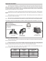
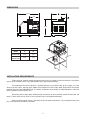
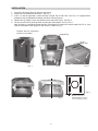
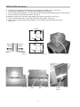
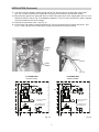
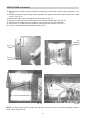
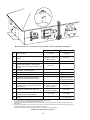
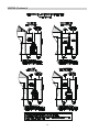
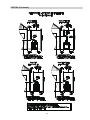
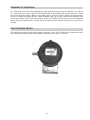
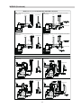
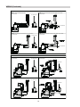
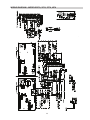
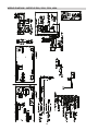
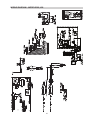
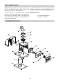
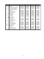
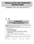
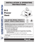
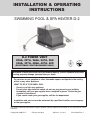
INSTALLATION & OPERATING
INSTRUCTIONS
SWIMMING POOL & SPA HEATER D-2
D-2 POWER VENT
206A, 207A, 266A, 267A, 268
336A, 337A, 406A, 407A, 408
(ELECTRONIC IGNITION MODELS ONLY)
WARNING: If these instructions are not followed exactly, a fire or explosion may result
causing property damage, personal injury or death.
Do not store or use gasoline or other flammable vapors and liquids in the vicinity
of this or any other appliance.
WHAT TO DO IF YOU SMELL GAS:
• Do not try to light any appliance.
• Do not touch any electrical switch; do not use any phone in your building.
• Immediately call your gas supplier from a neighbor's phone. Follow the gas
supplier's instructions.
• If you cannot reach your gas supplier, call the fire department.
Installation and service must be performed by a qualified installer, service agency
or the gas supplier.
This manual should be maintained in legible condition and kept adjacent to the heater or in a safe place for future
reference.
Catalog No. 6000.57.1F
Effective: 04-30-14
Replaces: 12-13-11
P/N 241243 Rev. 5
Rev. 5 reflects the following:
Changes to: Photo on page 1, “Receiving Equipment” on page 3, “Dimensions” drawing on page 4, Illustrated Parts List on
pages 22-23
Additions: None
Deletions: None
2
RECEIVING EQUIPMENT
On receipt of your equipment, it is suggested that you visually check for external damage to the carton.
If the carton is damaged, it is suggested that a note be made on the Bill of Lading when signing for equipment.
Remove the complete assembly from the carton. If it is damaged, report the damage to the carrier immediately. Be sure that you receive the number of packages indicated on the Bill of Lading. Claims for shortages and
damages must be filed with the carrier by consignee.
Purchased parts are subject to replacement only under the manufacturer’s warranty. Debits for defective replacement parts will not be accepted and defective parts will be replaced in kind only per our standard warranties.
When ordering parts, you must specify the kit number. When ordering under warranty conditions, you
must also specify the date of installation.
The manufacturer recommends that this manual be reviewed thoroughly before installing the D-2 Power
Vent. If there are any questions which this manual does not answer, please contact you local Representative.
THIS MANUAL SHOULD BE MAINTAINED IN LEGIBLE CONDITION AND KEPT ADJACENT TO THE UNIT.
(1) D-2 POWER VENT
(1) COLLAR ADAPTER
(1) 7/8” PLASTIC GROMMET
(1) ADJ. 90° ELBOW W/ SCREEN
(1) INSTALLATION AND OPERATING INSTRUCTIONS
(P/N 241243)
(1) 4” ADAPTER
4” Adapter
Comes separated
(assembles together)
Collar Adapter
Elbow with Screen
(Vent Termination)
D-2 Power Vent
(with Adapter in place)
GENERAL SPECIFICATIONS
The D-2 Power Vent is tested and certified to the latest edition of the American National Standard ANSI
Z21.56 standard for pool heaters.
The D-2 Power Vent is a fan-assisted combustion system designed for application to heater models 206
thru 408. When installed as directed, the unit is capable of operating in applications such as through-the-wall
venting and reduced horizontal and vertical vent pipe sizes in new and existing installations.
The D-2 Power Vent includes a blower with a 120/240 volt 60Hz 1.95/1.0A 3200 RPM motor and a
plenum, complete with a draft proving switch and a motor relay.
HEATER
MODELS
FACTORYWIRED
D-2 POWER VENT
PART NO.
336/337 - 406/407/408
240 VAC
009833
206/207 - 266/267/268
206/207 - 266/267/268
336/337 - 406/407/408
240 VAC
120 VAC
120 VAC
3
009832
010744
010745
DIMENSIONS
18.13
7.91
13.59
DIMENSIONAL DATA
Model
206/207
266/267/268
336/337
406/407/408
A
12.31
18.31
B
4.31
1.88
7.31
4.38
INSTALLATION REQUIREMENTS
Failure to install, maintain and/or operate the Power Vent in accordance with manufacturer’s instructions
may result in conditions which can produce bodily injury and property damage.
The equipment must be installed by a qualified installer in accordance with all local codes, or, in the
absence of local codes, with the latest edition of the National Fuel Gas Code, ANSI Z223.1/NFPA 54 and the
National Electrical Code, ANSI/NFPA 70. In Canada, installations must conform to CAN/CSA B149.1 and to the
latest Canadian Electrical Code Part 1.
Disconnect power supply when making wiring connections or when working around the fan blade and
motor. Failure to do so may result in severe personal injury and equipment damage.
Make certain the power source is adequate for the fan motor requirements. Do not add the Power Vent
to a circuit where the total load is unknown.
4
INSTALLATION
1. Start off by disconnecting main power to the heater.
2. Remove the front door from the heater. See Fig. 1.
3. If this is a retro-fit application, remove existing “Pagoda Top” and discard. See Fig. 2. If equipped with a
drafthood, refer to drafthood installation manual for removal process.
4. Remove the (6) Phillips screws that hold the jacket top to the heater. See Fig. 3.
5. Lift the rear end of the jacket top while inserting the collar adapter. See Fig. 4 & 5.
Note: Brackets are positioned underneath the collar adapter to capture the smaller model, See Fig. 6. Also
note the orientation of the adapter on the heater as shown in Fig. 7.
Remove door by unfastening
knurled screw shown.
Pagoda Top
(3) on
other side
Fig. 2
Fig. 1
Fig. 4
Fig. 5
5
Fig. 3
Fig. 6
Brackets used only on
206/207/336/337 models to
hold collar adapter in place
INSTALLATION (Continued)
6.
7.
8.
9.
10.
11.
12.
Lower the jacket top back onto the heater and reinstall the (6) Phillips screws. See Fig. 3.
If installing on a model 266, 267, 268, 406, 407 or 408 heater, skip step 8.
Turn the Power Vent upside down. Using a 5/16” nut driver, relocate the mounting brackets as shown in Fig. 8.
Place the Power Vent on top of the heater. See Fig. 9.
Move the Power Vent, so that the collar adapter slips into the Power Vent. See Fig. 10.
Push in all four bracket tabs, so the Power Vent locks into position. See Fig. 11.
Using a 5/16” nut driver, remove the transformer cover located on the right side of the heater.
See Fig. 12.
Before
Rear of
Heater
After
Front of
Heater
Fig. 7
Fig. 10
Fig. 8
Tab
Tab
6
Fig. 11
Fig. 9
Access
Screw
Fig. 12
INSTALLATION (Continued)
13. Install the right side outdoor conduit through the top 7/8” hole located on the right side of the heater.
See. Fig. 13. Note: You must first remove the 7/8” plug on the heater to install the hard conduit.
14. Wire the heater power lines along with the D-2 Power Vent power lines to the supply power per Fig. 15 for
010744 or 010745, and per Fig. 16 for 009832 or 009833. If the D-2 does not match the power supplied,
re-wire the blower for the correct voltage.
15. Reinstall the transformer cover. See Fig. 12.
16. Install the left side outdoor conduit through the top 7/8” hole located on the left side of the heater. See
Fig. 14. Note: You must first remove the 7/8” plug on the heater to install the conduit.
Power
Vent
Power
Supply
Fig. 13
Fig. 14
D-2 POWER VENT
009832 & 009833
D-2 POWER VENT
010744 & 010745
N FACTORY WIRED
L1 120 VOLTS
FACTORY WIRED
240 VOLTS
TO CONVERT FOR
120V OPERATION
TO CONVERT FOR
240V OPERATION
Fig. 15
Fig. 16
7
INSTALLATION (Continued)
17. Remove the (4) Phillips screws that hold the control panel to the heater and lower the control panel. See
Fig. 17.
18. Remove and replace the 7/8” plug with the provided 7/8” grommet (located on the left side of the control
panel). See Fig. 18.
19. Route the 24 VAC harness through the 7/8” grommet, See Fig. 19.
20. Continue to route the harness down through any available grommet hole. See Fig. 20.
21. Wire the harness along with the installed gas valve harness per the wiring diagram.
22. Reinstall the (4) Phillips screws that hold the control panel to the heater. See Fig. 17.
23. Place the front door back onto the heater. Refer to Fig. 1.
7/8”
Supplied
Grommet
Access
Screw
Access
Screw
Fig. 17
Fig. 18
Fig. 19
Fig. 20
NOTE: For Professional heaters, models 268 and 408, it may be necessary to reroute the flexible conduit to
either side of the power vent.
8
VENTING
The D-2 Power Vent operates with a positive vent static pressure and with a vent gas temperature that prevents
excessive condensate production in the vent, and as such, is a CATEGORY III appliance.
The total length of run shall not exceed an equivalent length of 100 ft including the termination cap. For all cases,
each 90° elbow reduces the maximum vent run by 10 ft and each 45° elbow reduces the run by 5 ft. The vent
must be installed properly to prevent the flue gas leakage within the heater. The vent pipe must be suitable for
use with Category III Appliances which have flue gas temperatures of less than 400°F. Care must be taken during the assembly to ensure that all joints are properly sealed.
For appliances installed in extremely cold climates, it is recommended that:
a) The vent be installed with a slight upward slope of not more than 1/4” per foot of horizontal run to the
vent terminal. In this case, an approved condensation trap must be installed per applicable codes.
b) The vent be insulated through the length of the horizontal run.
The exit terminal of the D-2 Power Vent shall not be less than 7 ft above grade where located adjacent to public walkways. It must also be at least 3 ft above any forced air inlet located within a 10 ft radius.
9
Minimum Clearances from Vent/Air Inlet Terminations—Indoor and Outdoor Installations
1
1
2
t
TT
*
2
U.S. Installations
Canadian Installations
A
Clearance above grade, veranda, porch,
deck, or balcony
1 ft (30 cm)
1 ft (30 cm)
B
Clearance to window or door that may be
opened
4 ft (1.2m) below or to side
of opening; 1 foot (30 cm)
above opening
3 ft (91 cm)
C
Clearance to permanently closed window
*
*
D
Vertical clearance to ventilated soffit located
above the terminal within a horizontal distance of 2 ft (61cm) from the centerline of the
terminal
5 ft (1.5m)
*
E
Clearance to unventilated soffit
*
*
F
Clearance to outside corner
*
*
G
Clearance to inside corner
6 ft (1.83m)
H
Clearance to each side of center line extended above meter/regulator assembly
*
3 ft (91 cm) within a
height 15 ft above the
meter/regulator assembly
I
Clearance to service regulator vent outlet
*
6 ft (1.83m)
J
Clearance to non-mechanical air supply inlet
to building or the combustion air inlet to any
other appliance
4 ft (1.2m) below or to side
of opening; 1 ft (30 cm)
above opening
3 ft (91 cm)
K
Clearance to mechanical air supply inlet
3 ft (91 cm) above if within
10 ft (3m) horizontally
6 ft (1.83m)
L
Clearance above paved sidewalk or paved
driveway located on public property
7 ft (2.13m)
7 ft (2.13m) t
M
Clearance under veranda, porch, deck or
balcony
*
12 in. (30 cm) TT
*
In accordance with the current ANSI Z223.1/NFPA 54 National Fuel Gas Code
In accordance with the current CAN/CSA-B149 Installation Codes
Vent terminal shall not terminate directly above sidewalk or paved driveway located between 2 single family dwellings that serves
both dwellings
Permitted only if veranda, porch, deck, or balcony is fully open on a minimum of two sides beneath the floor and top of terminal and
underside of veranda, porch, deck or balcony is greater than 1 ft (30cm)
Clearances in accordance with local installation codes and the requirements of the gas supplier
Vent/Air Inlet Termination Clearances
10
VENTING (Continued)
11
VENTING (Continued)
12
VENTING (Continued)
13
VENTING (Continued)
14
SEQUENCE OF OPERATION
On call for heat, the PC board will go through its safety chain (water pressure switch, high limit 1 & 2, roll-out,
etc.). When the safety chain is closed, the IID pilot will begin to spark and the pilot gas valve will open. A flame
will be lit at the pilot assembly. When an acceptable signal is sent back to the PC board, proving the rectification, the D-2 Power Vent blower will start. When the blower comes up to speed, a draft proving switch will close
to allow the main gas valve on the heater to open. Note: On Low NOx units, the main gas valve & combustion
blower will turn on simultaneously. A heater with a D-2 Power Vent will continue to operate until call for heat is
satisfied.
DRAFT-PROVING SWITCH
The draft-proving switch ensures that the blower is operating. Once the D-2 Power Vent is wired to the heater,
the switch does not allow the PC board to open the main gas valve, unless it is closed.
15
WIRING
The D-2 Power Vent includes a wire harness which provides quick connections with the respective controls in
the appliance control box. The harness is of sufficient length to fit the unit for which it is sized.
Reference the connection diagrams on pages 17 & 18 or the wiring diagrams on pages 19 through 21 for actual connections.
RELAY
Y/BK
V/BK
V/BK
V/W
Y/BK
Y/BK
V/BK
V/W
GAS VALVE
16
AIR
PRESSURE
SWITCH
WIRING (Continued)
MODELS 207, 267, 337, 407 EQUIPPED WITH HONEYWELL GAS VALVE
: VERIFY CURRENT CONNECTIONS
AS SHOWN BELOW.
P4
1
D-2 POWER VENT
STEP 3 : CONNECT THE RETURN LINES, FEMALE SPADES TO MALE SPADES
AS SHOWN BELOW.
Y/BK
P4
D-2 POWER VENT
Y/BK
M/MV
V/BK
AS SHOWN BELOW.
P4
RELAY
G/BK
M/MV
D-2 POWER VENT
R/BK
V/W
V/BK
P/PV
HONEYWELL
VALVE
V/BK
C/
MV
PV
Y/BK
Y/BK
M/MV
1
Y/BK
V/BK
Y/BK
Y/BK
Y/BK
Y/BK
Y/BK
MV
PV
V/BK
V/BK
Y/BK
HONEYWELL
VALVE
C/
V/W
V/BK
STEP 4 : CONNECT THE MAIN VALVE LINES, FEMALE SPADES TO MALE SPADES
GROUND
ON VALVE
R/BK
P/PV
Y/BK
Y/BK
G/BK
RELAY
1
MV
PV
V/BK
AS SHOWN BELOW.
HONEYWELL
VALVE
C/
V/BK
V/BK
STEP 2 : DISCONNECT BOTH TERMINALS MVPV & MV
V/W
V/BK
V/BK
R/BK
P/PV
V/BK
M/MV
Y/BK
Y/BK
Y/BK
Y/BK
HONEYWELL
VALVE
MV
PV
1
G/BK
V/BK
V/BK
Y/BK
R/BK
P/PV
C/
P4
RELAY
G/BK
RELAY
Y/BK
V/BK
STEP
Y/BK
D-2 POWER VENT
V/W
MODELS 207, 267, 337, 407 EQUIPPED WITH INVENSYS/ROBERTSHAW GAS VALVE
STEP 3 : CONNECT THE RETURN LINES, FEMALE SPADES TO MALE SPADES
AS SHOWN BELOW.
INVENSYS/
ROBERTSHAW
VALVE
V/BK
V/BK
TH
V/W
Y/BK
Y/BK
Y/BK
V/BK
R/BK
R/BK
D
STEP 2 : DISCONNECT BOTH TERMINALS TH & TR ON HARNESSES
AS SHOWN BELOW.
P4
1
D-2 POWER VENT
+
D
Y/BK
TR
INVENSYS/
ROBERTSHAW
VALVE
G/BK
D
INVENSYS/
ROBERTSHAW
VALVE
R/BK
P4
V/BK
V/BK
TH
V/BK
D
R/BK
17
+
Y/BK
V/W
1
D-2 POWER VENT
Y/BK
V/W
Y/BK
Y/BK
TR
Y/BK
V/BK
Y/BK
D
+
Y/BK
Y/BK
V/BK
TH
R/BK
AS SHOWN BELOW.
RELAY
Y/BK
V/BK
R/BK
STEP 4 : CONNECT THE MAIN VALVE LINES, FEMALE SPADES TO MALE SPADES
RELAY
V/BK
Y/BK
Y/BK
D
TR
INVENSYS/
ROBERTSHAW
VALVE
R/BK
Y/BK
Y/BK
R/BK
V/W
D
TR
D-2 POWER VENT
V/BK
D
V/BK
1
V/W
G/BK
TH
Y/BK
V/BK
V/BK
Y/BK
Y/BK
Y/BK
Y/BK
+
RELAY
V/BK
RELAY
P4
V/BK
D-2 POWER VENT
G/BK
1
G/BK
P4
Y/BK
AS SHOWN BELOW.
Y/BK
STEP 1 : VERIFY CURRENT CONNECTIONS
WIRING (Continued)
MODELS 206, 266, 268, 336, 406, 408 EQUIPPED WITH HONEYWELL GAS VALVE
P4
1
D-2 POWER VENT
STEP 3 : CONNECT THE RETURN LINE, FEMALE SPADE TO MALE SPADE
P4
AS SHOWN BELOW.
1
V/BK
G/BK
G/BK
AS SHOWN BELOW.
Y/BK
STEP 1 : VERIFY CURRENT CONNECTIONS
R/BK
STEP 2 : DISCONNECT BOTH TERMINALS MVPV & MV FROM VALVE
P4
1
D-2 POWER VENT
Y/BK
Y/BK
MV
PV
M/MV
V/W
AS SHOWN BELOW.
1
G/BK
M/MV
P/PV
V/BK
Y/BK
Y/BK
V/W
MV
PV
Y/BK
HONEYWELL
VALVE
C/
D-2 POWER VENT
STEP 4 : CONNECT THE MAIN VALVE LINE, FEMALEP4SPADE TO MALE SPADE
R/BK
P/PV
Y/BK
V/BK
G/BK
AS SHOWN BELOW.
HONEYWELL
VALVE
C/
HONEYWELL
VALVE
V/BK
C/
MV
PV
Y/BK
M/MV
R/BK
Y/BK
Y/BK
V/W
V/BK
V/BK
R/BK
P/PV
V/BK
M/MV
Y/BK
Y/BK
V/W
MV
PV
Y/BK
HONEYWELL
VALVE
C/
V/BK
P/PV
D-2 POWER VENT
MODELS 206, 266, 268, 336, 406, 408 EQUIPPED WITH INVENSYS/ROBERTSHAW GAS VALVE
STEP 1 : VERIFY CURRENT CONNECTIONS
P4
1
D-2 POWER VENT
STEP 3 : CONNECT THE RETURN LINE, FEMALE SPADE TO MALE SPADE
AS SHOWN BELOW.
P4
1
D-2 POWER VENT
R/BK
D
STEP 2 : DISCONNECT BOTH TERMINALS TH & TR
AS SHOWN BELOW.
1
D-2 POWER VENT
D
Y/BK
R/BK
R/BK
STEP 4 : CONNECT THE MAIN VALVE LINE, FEMALE SPADE TO MALE SPADE
AS SHOWN BELOW.
P4
D
R/BK
V/BK
V/W
Y/BK
TH
V/BK
D
R/BK
18
+
D
INVENSYS/
ROBERTSHAW
VALVE
R/BK
1
D-2 POWER VENT
V/BK
Y/BK
TR
Y/BK
Y/BK
Y/BK
+
INVENSYS/
ROBERTSHAW
VALVE
Y/BK
Y/BK
V/W
D
TR
Y/BK
TH
V/W
Y/BK
V/BK
G/BK
P4
+
INVENSYS/
ROBERTSHAW
VALVE
R/BK
V/W
R/BK
TR
V/BK
V/BK
V/W
Y/BK
TH
V/BK
D
Y/BK
V/BK
G/BK
+
INVENSYS/
ROBERTSHAW
VALVE
Y/BK
D
TR
Y/BK
TH
Y/BK
Y/BK
G/BK
G/BK
AS SHOWN BELOW.
WIRING DIAGRAM – MODELS 207A, 267A, 337A, 407A
19
WIRING DIAGRAM – MODELS 206A, 266A, 336A, 406A
20
WIRING DIAGRAM – MODELS 268, 408
21
REPLACEMENT PARTS
If determined defective by the Company and within
warranty, a like part or equal substitution will be
returned, freight collect. Credit will not be issued.
NOTE: To supply you with the correct part, it is important that you supply the heater model number, serial
number and type of gas when applicable.
Any part returned for replacement under standard
company warranties must be properly tagged with a
return parts tag, completely filled in with the heater
serial number, model number, etc., and shipped to the
Company freight prepaid.
MANUFACTURER:
2151 EASTMAN AVENUE
OXNARD, CA 93030
ILLUSTRATED PARTS LIST
4
9
16
5
10
11
2
15
12
1
6
3
14
7
13
8
22
Call Out
1
2
3
4
5
Description
DPDT Relay
Blower
N.O. Air Pressure Switch
4"-90° Elbow w/Screen
Combustion Flue Box
Green
Cool Dark Gray
6
Base Assembly
7
Flue Collar
8
Flue Adapter
9
4" Flange
16 Seal Gasket
10
Blower Adapter
Green
Cool Dark Gray
11
Control Cover
Green
Cool Dark Gray
12
Control Swaybrace
13
Silicone Hose
14
Front Panel
Green
Cool Dark Gray
15
Blower Cooling Fan
206/207
008784F
008156F
008062F
010827F
266/267/268
008784F
008156F
008062F
010827F
336/366
008784F
008156F
008135F
010827F
406/407/408
008784F
008156F
008135F
010827F
008682F
013854F
010821F
008686F
010823F
008689F
015040F
008682F
013854F
010821F
008686F
010823F
008689F
015040F
008683F
013855F
010822F
008686F
010824F
008689F
015040F
008683F
013855F
010822F
008686F
010824F
008689F
015040F
008690F
013858F
008690F
013858F
008690F
013858F
008690F
013858F
008691F
013856F
008692F
008693F
008691F
013856F
008692F
008693F
008691F
013856F
008692F
008693F
008691F
013856F
008692F
008693F
008694F
013857F
011549F
008694F
013857F
011549F
008694F
013857F
011549F
008694F
013857F
011549F
23
www.raypak.com
Raypak, Inc., 2151 Eastman Avenue, Oxnard, CA 93030 (805) 278-5300 Fax (805) 278-5468
Litho in U.S.A.
24