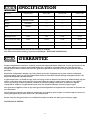
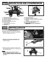
1
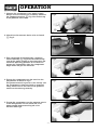
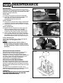
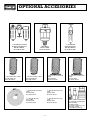
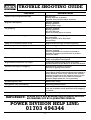
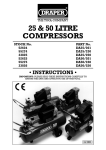
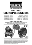
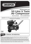
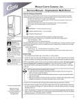
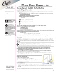
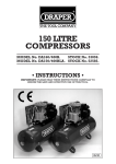
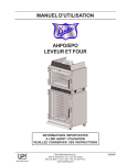
50, 100 & 120 LITRE
COMPRESSORS
STOCK No.
54277
54678
52353
52355
MODEL No.
DA100/15BLA
DA50/90HP
DA100/15HP
DA120/29HP
• INSTRUCTIONS •
IMPORTANT: PLEASE READ THESE INSTRUCTIONS CAREFULLY TO
ENSURE THE SAFE AND EFFECTIVE USE OF THIS TOOL.
01/98
NOTE: WHEELS NOT SUPPLIED AS STANDARD
50, 100 & 120 LITRE COMPRESSORS
■ STOCK Nos. 54277, 54678, 52353, 52355.
■ MODEL Nos. DA100/15BLA, DA50/90HP, DA100/15HP, DA120/29HP.
Whilst every effort has been made to ensure accuracy of information given in this manual is correct at the
time of going to print, the Draper Tools policy of continuous improvement determines the right to change
specification without notice.
CONTENTS:
Page Nos.
Specification / Guarantee.................................................................................................................... 3
Safety Warning .................................................................................................................................... 4
General Safety Warning for Compressors and Air Tools ..................................................................... 4
Power Supply ...................................................................................................................................... 5
Know Your Air Compressor ................................................................................................................. 6
Operation............................................................................................................................................ 6-7
Operation Cont’d................................................................................................................................. 7
Maintenance........................................................................................................................................ 7
Maintenance Cont’d ............................................................................................................................ 8
Optional Accessories ......................................................................................................................... 9-10
Trouble Shooting Guide ..................................................................................................................... 11
DECLARATION OF CONFORMITY
We
Draper Tools Ltd. Hursley Road, Chandler's Ford, Eastleigh, Hampshire SO53 1YF. England.
Declare under our sole responsibility that the products:
Part Number:- DA100/15BLA, DA50/90HP, DA100/15HP & DA120/29HP.
Stock Number:- 54277, 54678, 52353 & 52355.
Description:- Compressors 50, 100 and 120 Litres.
To which this declaration relates is in conformity with the following directive(s):89/392EEC, 87/404EEC & 89/336EEC.
J.N. DRAPER
Managing Director
-2-
SPECIFICATION
Model No.
DA100/15BLA
DA50/90HP
DA100/15HP
DA120/29HP
Stock No.
54277
54678
52353
52355
3HP BELT DRIVEN
----
----
----
230V/50Hz.
----
----
----
R.P.M.
1000rpm
----
----
----
Engine
----
4HP Honda
5.3HP Honda
9HP Honda
145psi (10 bar)
145psi (10 bar)
145psi (10 bar)
145psi (10 bar)
Air displacement
14cfm
9cfm
15cfm
29cfm
Free air delivered (FAD)
10cfm
5.8cfm
11cfm
22cfm
100 litres
50 litres
100 litres
120 litres
108kg.
75kg.
124kg.
170kg.
Motor
Voltage
Maximum pressure
Receiver capacity
Weight
The typical sound pressure level of this machine is 77db(A).
The noise level whilst working, could exceed 85db(A) - WEAR EAR PROTECTION.
GUARANTEE
Draper compressors have been carefully tested and inspected before shipment and are guaranteed to be
free from defective materials and workmanship for a period of 12 months from the date of purchase
except where tools are hired out when the guarantee period is reduced to ninety days from the date of
purchase.
Should the compressor develop any fault, please return the complete tool to your nearest authorized
warranty repair agent or contact Draper Tools Limited, Chandler's Ford, Eastleigh, Hampshire, SO53 1YF.
England. Telephone: (01703) 266355.
If upon inspection it is found that the fault occurring is due to defective materials or workmanship, repairs
will be carried out free of charge. This guarantee does not apply to normal wear and tear, nor does it
cover any damage caused by misuse, careless or unsafe handling, alterations, accident, or repairs
attempted or made by any personnel other than the authorized Draper warranty repair agent.
This guarantee applies in lieu of any other guarantee expressed or implied and variations of its terms are
not authorized.
Your Draper guarantee is not effective unless you can produce upon request a dated receipt or invoice to
verify your proof of purchase within the 12 month period.
Please note that this guarantee is an additional benefit and does not affect your statutory rights.
DRAPER TOOLS LIMITED
-3-
SAFETY WARNING
WARNING:
Please read the following instructions carefully. Failure to do so could lead to serious personal injury.
IMPORTANT:
Draper Tools recommends that this compressor should not be modified or used for any application other
than that for which it was designed. If you are unsure of it’s relative applications do not hesitate to contact
us in writing and we will advise you.
GENERAL SAFETY RULES FOR
AIR COMPRESSORS AND TOOLS
1. KNOW YOUR COMPRESSOR
Before operating the compressor, read and
fully understand the starting, operating and
stopping sections in this manual. Read all
labels affixed to the compressor. Learn it’s
applications and limitations.
8. AVOID ACCIDENTAL STARTING
Make sure the power supply switch is off
before connecting to the power supply.
9. KEEP CHILDREN AWAY AND MAKE
WORKSHOP CHILDPROOF
All visitors should be kept a safe distance
from the work area. The power tools and
workshop should be made childproof with
padlocks, master switches or by removing
starter keys.
2. SERVICING AND MAINTENANCE
Do not service or maintain this compressor
until you have read and understood the
maintenance section of this manual.
3. CHECK DAMAGED PARTS
Before further use of this compressor a guard
or other part that is damaged should be
carefully checked to ensure that it will operate
correctly and perform its intended function.
Check for alignment of moving parts,
breakage of parts and any other conditions
that may effect its operation. A guard or other
part that is damaged should be properly
repaired or replaced.
10. NEVER LEAVE THE COMPRESSOR
RUNNING UNATTENDED
Turn the power supply off. Do not leave the
compressor until it comes to a complete stop.
11. DO NOT OVERLOAD THE COMPRESSOR
Before operating any air tool check that
the free air delivery (FAD) from the air
compressor is equal or greater than that of the
air tool to be used. NOTE: the compressor
should not start more than nine times in one
hour.
4. DISCONNECT FROM POWER SUPPLY
Before servicing, maintaining or replacing
damaged parts ALWAYS disconnect the
compressor from the power supply.
12. AIR PRESSURE
Always check that the air supply pressure is
equal to or less than the air tool
manufacturers maximum operating pressure.
5. EARTH
This compressor is equipped with an
approved 3-core power cable. The green and
yellow conductor in the core is the earth wire.
NEVER connect the yellow and green wire to a
live terminals.
13. USE SAFETY GOGGLES/MASK
Wear safety goggles (which comply to a
recognized standard) at all times. Normal
spectacles only have impact resistant lenses,
they are NOT safety glasses. Also use a face
mask if a cutting operating is dusty or if
spraying paint or other toxic substances.
6. AVOID DANGEROUS ENVIRONMENTS
Do not use the compressor is damp or wet
locations or expose it to rain. Keep the work
area well lit. Provide adequate surrounding
work space.
*Not suitable for building sites.
14. USE RECOMMENDED ACCESSORIES
For a complete range of recommended
accessories please refer to page 9 of this
manual.
7. KEEP GUARDS IN PLACE
-4-
POWER SUPPLY
CONNECTING YOUR COMPRESSOR TO THE POWER SUPPLY: (DA100/15BLA ONLY)
A separate electrical socket should be used for your machine. The circuit should not be less that a 13 amp
ring main which should be protected by a 30 amp fuse or miniature circuit breaker rated at 30 amps. If an
extension cable is used, use only 3-core extension leads with 3-pin sockets which will accept the
machine’s plug. For distances up to 100 feet use 16 gauge .064 = 2.5mm wire: for distances up to 150 feet
use 14 gauge .080 = 3.0mm wire. A qualified electrician should replace or repair damaged or worn cables
immediately.
Before connecting the motor to the power supply, make sure the switch is in ‘OFF’ position and that the
electric current is of the same characteristics as stamped on the motor rating plate. All cable connections
should make good contact. Running on low voltage will damage the motor. See extension lead chart
below.
WARNING
Single phase 230 volt machines must be connected using the relevant coding and matching the colour of
the flexible cable to that of the plug.
The procedure is as follows:
1. Connect green and yellow coloured core to the plug terminal marked letter ‘E’ earth symbol or
coloured green or green and yellow.
2. Connect brown coloured core to plug terminal marked letter ‘L’ (live).
3. Connect blue colour core to plug terminal marked letter ‘N’ (neutral).
N.B. Three phase machines must be connected by a qualified electrician.
NOTE:
FOR COMPRESSORS FITTED WITH A HONDA PETROL ENGINE PLEASE REFER TO THE
MANUFACTURER’S INSTRUCTION MANUAL.
-5-
KNOW YOUR AIR COMPRESSOR
✱✌
✮✌
✬✌
✲✌
✫✌
✪✌
✭✌
✰✌
✯✌
✳✌
✴✌
✪✌ PRESSURE GAUGE
indicates air pressure in receiver
✫✌ ON/OFF SWITCH (PRESSURE SWITCH)
✬✌ MOTOR/ ENGINE
✭✌ RESERVOIR INSPECTION PLUG
✮✌ PULLEY GUARD
covers, protects moving parts
✯✌ AIR RECEIVER
stores air
FOR FRAME & WHEEL KIT SEE PAGE 10 FOR
OPTIONAL ACCESSORIES.
✰✌ AIR OUTLET VALVE
releases air from the reservoir
✱✌ THERMAL OVERLOAD PROTECTION RESET
SWITCH
✲✌ OVERLOAD SAFETY RELIEF VALVE
✳✌ RESERVOIR DRAIN VALVE
✴✌ NOTE: WHEELS NOT SUPPLIED AS
STANDARD
INSTALLATION
After removing the compressor from the
packaging, check that it is in perfect condition.
Fig.1.
1. Replace the plastic cap on the motor housing
with the oil dipstick ✪✌ (Fig.1.)
✪✌
2. Check the oil level, this is indicated on the
dipstick by two notches for minimum and
maximum (Fig.2.)
Fig.2.
MAX.
MIN.
3. Ensure that there is adequate ventilation and
that the safety area around the compressor is at
least 1 metre. (Fig.3.)
➜
Fig.3.
NOTE:
FOR COMPRESSORS FITTED WITH A
HONDA PETROL ENGINE, PLEASE REFER
TO THE MANUFACTURER’S INSTRUCTION
MANUAL.
1M.
1M
-6-
➜
OPERATION
1. Connect the compressor to the power supply.
Always turn the machine on and off by means of
the appropriate switch ✫✌ Fig.4 located on top
of the pressure switch box.
Fig.4.
✫✌
2. Check that the reservoir drain valve is closed
✬✌ Fig.5.
Fig.5.
✬✌
3. This compressor is controlled by a pressure
switch assembly ✭✌ Fig.6 which automatically
cuts off the power supply to the motor when the
maximum operating pressure is reached and
restarts the compressor when the compressor
drops below the pre-set minimum.
Fig.6.
✭✌
4. To start the compressor turn the switch to the
ON position as shown in Fig.7.
The pressure switch is pre-set at the factory and
the compressor is also fitted with an overload
safety relief valve in the event of the pressure
switch not functioning correctly.
Fig.7.
5. To stop the compressor turn the pressure switch
to the OFF position. Do not switch off at the
power supply before switching off at the
machine. See Fig.8.
Fig.8.
-7-
MAINTENANCE
IMPORTANT:
Before performing any maintenance operations,
disconnect the compressor from the power supply
and release all the air from the receiver until the
pressure gauge reads zero.
Fig.9.
✯✌
EVERY DAY:
A. Check the oil level and top up if required.
B. Drain the condensate from the receiver. The
drain plug ✯✌ Fig.9 is situated on the
underside of the receiver tank.
EVERY MONTH:
A. Clean the air suction filter using compressed
air. Replace the filter every 500 hours of use.
B. Check the tension of the drive belt and adjust
as necessary.
Fig.10.
EVERY 500 HOURS:
A. Replace the oil. Remove the drain plug ✰✌
Fig.10 and drain the oil into a suitable
container. Refit the drain plug and refill the
crank case with new oil to the correct level.
B. Clean all the external surfaces of the pump
unit and motor. Ensure that neither the motor
fan cowling ✱✌ or head cooling fins ✲✌ are
blocked or obstructed in any way. See Fig.11.
✰✌
✲✌
EVERY 2000 HOURS:
Check the condition of the valves and replace
them if they are damaged or worn.
NOTE:
FOR COMPRESSORS FITTED WITH A
HONDA PETROL ENGINE PLEASE REFER
TO THE MANUFACTURER’S INSTRUCTION
MANUAL.
Fig.11.
✱✌
PRESSURE SWITCH SETTINGS:
The delivery pressure setting can drift over a
period of time and will require periodic
adjustment. Ensure that the pressure switch
settings are correctly adjusted and maintained at
the correct level. This will help prevent faulty
occurring which can result in reduced
performance and possible failure.
Fig.12.
PRESSURE SWITCH ADJUSTMENTS:
To adjust the pressure level at which the cut-out
functions, remove the switch cover and turn the
pressure regulating screw clockwise to increase
the level and anticlockwise to decrease the level.
See Fig.12.
To adjust the cut-in pressure turn the cut-in
pressure regulating screw clockwise to increase
and anticlockwise to decrease the level.
WARNING:
DO NOT ADJUST THE CUT-OUT LEVEL ABOVE
THE MAXIMUM PRESSURE AS PER THE
MACHINE SPECIFICATION.
-8-
OPTIONAL ACCESSORIES
1
⁄2" Combination Filter
Regulator/Lubricator
Part No.4222/3.
Stock No.51857.
1
Mini Oiler
Part No.4255.
Stock No.22317.
⁄2" Combined
Filter/Regulator
Part No.4222/3.
Stock No.51858.
HEAVY DUTY
1
1
⁄4" Recoil Air Hose (25ft)
Part No.4225/1A.
Stock No.52662.
⁄4" Nylon Recoil Air Hose
(25ft)
Part No.4282.
Stock No.27742.
3
⁄8" Recoil Air Hose (25ft)
Part No.4225/2A.
Stock No.52663.
1
⁄4" Straight Air Line Hose
(50ft)
Part No.4306.
Stock No.36939.
3
⁄8" Straight Air Line Hose
(50ft)
Part No.4308.
Stock No.36941.
5
1
⁄2" Straight Air Line Hose
(50ft)
Part No.4309.
Stock No.36942.
⁄16" Straight Air Line
Hose (50ft)
Part No.4307.
Stock No.36940.
-9-
HEAVY DUTY
3
⁄8" Nylon Recoil Air Hose
(25ft)
Part No.4283.
Stock No.27743.
3 pce Air Line Coupling Set
Part No.ACK1.
Stock No.27740.
See Draper Catalogue for
full range of PCL
couplings and fittings
OPTIONAL ACCESSORIES Cont'd
PART No.
DESCRIPTION
TO SUIT
STOCK No.
ADA 50F
FRAME AND BRACKET KIT (WHEELS NOT INCLUDED).
DRAPER COMPRESSORS DA50/90B & DA50/91B.
37132.
PART No.
DESCRIPTION
TO SUIT
STOCK No.
ADA 50PF
FRAME AND BRACKET KIT (WHEELS NOT INCLUDED).
DRAPER COMPRESSOR DA50/90HP.
54658.
PART No.
DESCRIPTION
TO SUIT
STOCK No.
ADA 100F
FRAME AND BRACKET KIT (WHEELS NOT INCLUDED).
DRAPER COMPRESSORS DA100/15B & DA100/15P.
37140.
PART No.
DESCRIPTION
TO SUIT
STOCK No.
ADA 120F
FRAME AND BRACKET KIT (WHEELS NOT INCLUDED).
DRAPER COMPRESSOR DA120/29P.
37141.
PART No.
DESCRIPTION
TO SUIT
STOCK No.
ADAW
10" SOLID WHEEL.
ALL FRAME AND BRACKET KITS.
37131.
PLEASE NOTE:
WHEELS WILL ONLY FIT MACHINE WHEN ASSEMBLED
COMPLETE WITH FRAME AND BRACKET KIT.
- 10 -
TROUBLE SHOOTING GUIDE
SYMPTOMS
POSSIBLE CAUSES
Thermal overload protection trips.
Oil level low.
Wrong direction of rotation.
Pressure switch failure/motor overload.
High oil consumption.
Air filter clogged.
Wrong type of oil.
Broken piston rings.
Oil pumping.
Air filter clogged.
Wrong type of oil
Oil level too high.
Piston scratched, worn or scored.
Noisy operation (knocking).
Loose drive pulley, coupling or excessive wear in
the motorshaft.
Loose fly wheel, drive belt loose.
Low oil level.
Milky oil in crankcase (water in oil).
High humidity. Change oil more frequently.
Oil in compressor air supply.
Air filter clogged, oil level too high.
Low air output.
Kinked hose, leaking connections.
Air filter clogged.
Piston rings broken or incorrectly seated in.
Cylinder or piston scratched, worn or scored.
Drive belt loose.
Excessive belt drive wear.
Belt loose - slipping, belt too tight.
Pulley and flywheel misaligned.
High moisture contents in air output.
Caused by high humidity. Drain any excess
moisture from receiver. Move to an area less humid.
Excessive starting and stopping.
High moisture content in receiver.
Air leaks in piping/connections.
Compressor will not start.
Power cable faulty, fuse blown, circuit breaker
open. Motor thermal overload protection tripped or
faulty. Pressure switch faulty. Check if the receiver
pressure is higher than the pressure switch cut-out
pressure (motor will re-start when the receiver
pressure drops below the cut-in pressure).
Air blowing from inlet.
Broken inlet valves.
Compressor runs continuously.
Defective pressure switch.
Compressor runs but does not produce air.
Check all valves are closed. Inspect all gasket in
case one is broken check drive belt is not slipping
or broken.
General air leaks.
These result from poor seals on some fittings.
IMPORTANT:
PLEASE NOTE ALL REPAIRS/ADJUSTMENTS SHOULD
BE CARRIED OUT BY A QUALIFIED PERSON.
POWER DIVISION HELP LINE:
01703 494344
- 11 -
DRAPER TOOLS LTD.
Hursley Road, Chandler’s Ford,
Eastleigh, Hants. SO53 1YF. England.
Tel: (01703) 266355.
Fax: (01703) 260784.
YOUR DRAPER STOCKIST
©Published by Draper Tools Ltd.
No part of this publication may be reproduced,
stored in a retrieval system or transmitted in any
form or by any means, electronic, mechanical
photocopying, recording or otherwise without
prior permission in writing from Draper Tools Ltd.