1
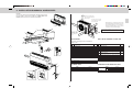
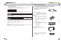
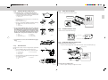
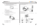
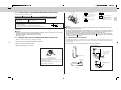
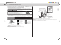
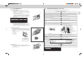
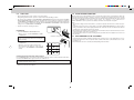
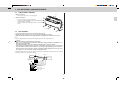
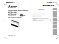
Floor and Ceiling Type Air-Conditioner
MCFZ-A18WV
MCFZ-A24WV
[FLARE CONNECTION TYPE]
CONTENTS
1. THE FOLLOWING SHOULD ALWAYS BE OBSERVED FOR
SAFETY ........................................................................................... 2
HFC
utilized
R410A
INSTALLATION MANUAL
2. SELECTING THE INSTALLATION LOCATION ............................... 2
3. INSTALLATION DIAGRAM & ACCESSORIES ................................ 3
4. INDOOR UNIT INSTALLATION ....................................................... 4
5. OUTDOOR UNIT INSTALLATION ................................................... 9
6. INDOOR/OUTDOOR UNIT CONNECTION FINISHING AND
TEST RUN ..................................................................................... 10
7. FOR MOVEMENT AND MAINTENANCE ...................................... 13
FOR INSTALLER
English
1. THE FOLLOWING SHOULD ALWAYS BE OBSERVED FOR
SAFETY
2. SELECTING THE INSTALLATION LOCATION
• Please provide an exclusive circuit for the air conditioner and make sure that no other electrical
appliances are connected to it.
• Be sure to read “THE FOLLOWING SHOULD ALWAYS BE OBSERVED FOR SAFETY” before installing
the air conditioner.
• Be sure to observe the cautions specified here as they include important items related to safety.
• The indications and meanings are as follows.
Warning: Could lead to death, serious injury, etc.
Caution: Could lead to serious injury in particular environments when operated incorrectly.
• After reading this manual, be sure to keep it together with the instruction manual in a handy place on
the customer’s site.
2-1
Warning
■ Perform electrical work according to the installation manual and be sure to use an exclusive circuit.
If the capacity of the power circuit is insufficient
or there is incomplete electrical work, it could
result in a fire or an electric shock.
■ Attach the electrical part cover to the indoor
unit and the service panel to the outdoor unit
securely.
If the electrical part cover in the indoor unit and/
or the service panel in the outdoor unit are not
attached securely, it could result in a fire or an
electric shock due to dust, water, etc.
■ Be sure to use the part provided or specified
parts for the installation work.
The use of defective parts could cause an injury
or leakage of water due to a fire, an electric shock,
the unit falling, etc.
■ Be sure to cut off the main power in case of
setting up the indoor electronic control P.C.
board or wiring works.
It could cause an electric shock.
■ The appliance shall be installed in accordance
with national wiring regulations.
■ When installing or relocating the unit, make
sure that no substance other than the specified refrigerant (R410A) enters the refrigerant
circuit.
Any presence of foreign substance such as air
can cause abnormal pressure rise or an explosion.
2-2
• Mounting
Select a position about 1.2 m above the floor, check that signals from the controller are surely received by
the indoor unit from that position (‘beep’ or ‘beep-beep’ receiving tone sounds), attach remote controller
holder 4 to a pillar or wall, then set the wireless remote controller 3.
In rooms where inverter type fluorescent lamps are used, the signal from the wireless remote controller may
not be received.
2-3
•
•
•
•
•
■ Perform the drainage/piping work securely
according to the installation manual.
If there is a defect in the drainage/piping work,
water could drop from the unit and household
goods could be wet and damaged.
■ Fasten a flare nut with a torque wrench as
specified in this manual.
When fastened too tight, a flare nut may broken
after a long period and cause a leakage of refrigerant.
500 mm
OUTDOOR UNIT
Where it is not exposed to strong wind.
Where airflow is good and dustless.
Where it is not exposed to rain and direct sunshine.
Where neighbours are not annoyed by operation sound or hot air.
Air outlet
Where rigid wall or support is available to prevent the increase
840 mm
of operational sound or vibration.
Where there is no risk of combustible gas leakage.
4-10 mm × 21 mm slot
When installing the unit at a high level, be sure to fix the unit legs.
Where it is at least 3 m away from the antenna of TV set or radio. Operation of the air conditioner interferes
with radio or TV reception in areas where reception is weak. An amplifier may be required for the affected
device.
Install the unit horizontally.
Please install it in an area not affected by snowfall or blowing snow. In areas with heavy snow, please install
a canopy, a pedestal and/or some baffle boards.
360 mm
•
•
•
•
•
Caution
■ Earth the unit.
Do not connect the earth to a gas pipe, water
pipe, lightning rod or telephone earth. Defective
earthing could cause an electric shock.
■ Do not install the unit in a place where an inflammable gas leaks.
If gas leak and accumulate in the area surrounding the unit, it could cause an explosion.
■ Install an earth leakage breaker depending on
the installation place (Where it is humid).
If an earth leakage breaker is not installed, it could
cause an electric shock.
WIRELESS REMOTE CONTROLLER MOUNTING
• Place of mounting
- Where it is easy to operate and easily visible.
- Where children cannot touch.
330 mm
■ Do not install it by yourself (customer).
Incomplete installation could cause injury due to
fire, electric shock, the unit falling or leakage of
water. Consult the dealer from whom you purchased the unit or special installer.
■ Install the unit securely in a place which can
bear the weight of the unit.
When installed in an insufficient strong place, the
unit could fall causing injury.
■ Use the specified wires to connect the indoor
and outdoor units securely and attach the
wires firmly to the terminal block connecting
sections so the stress of the wires is not applied to the sections.
Incomplete connecting and fixing could cause a fire.
■ Do not use intermediate connection of the
power cord or the extension cord and do not
connect many devices to one AC outlet.
It could cause a fire or an electric shock due to
defective contact, defective insulation, exceeding the permissible current, etc.
■ Check that the refrigerant gas does not leak
after installation has completed.
If refrigerant gas leaks indoors, and comes into
contact with the fire of a fan heater, space heater,
stove, etc., harmful substances will be generated.
■ Perform the installation securely referring to
the installation manual.
Incomplete installation could cause a personal
injury due to fire, electric shock, the unit falling or
leakage of water.
INDOOR UNIT
• Where airflow is not blocked.
• Where cool air spreads over the entire room.
• Maximum refrigerant piping length between indoor unit and outdoor unit is 30 m and the difference of height
of both units is 15 m.
• Rigid wall or ceiling without vibration.
• Where it is not exposed to direct sunshine.
• Where easily drained.
• At a distance 1 m or more away from your TV and radio. Operation of the air conditioner interferes with radio
or TV reception in areas where reception is weak. An amplifier may be required for the affected device.
• In a distance as far as possible from fluorescent and incandescent lights (so the infrared remote control can
operate the air conditioner normally).
• Where the air filter can be removed and replaced easily.
Note:
It is advisable to make a piping loop near outdoor unit so as to reduce vibration transmitted from there.
Caution:
Avoid the following places for installation where air conditioner trouble is liable to occur.
• Where flammable gas could leak.
• Where there is much machine oil.
• Salty places such as the seaside.
• Where sulfide gas is generated such as a hot spring.
• Where there is high-frequency or wireless equipment.
2
3. INSTALLATION DIAGRAM & ACCESSORIES
Remark:
Accessories of this unit are packed inside the unit. Please remove
the front grille as shown in the right (See “FRONT GRILL REMOVAL”), and check accessories before installation.
Open as a rule 500 mm or
more if the front and both
sides are open
100 mm or more 200 mm
or more if there are obstacles to both sides
100
When the piping is to be attached to a wall containing metals (tin plated) or metal netting, use a chemically treated wooden piece 20 mm or thicker between the wall and the piping or wrap 7 to 8 turns
of insulation vinyl tape around the piping.
or m
ore
Accessories
Front grille
mm
2
Units should be installed by licensed contractor accordingly
to local code requirement.
1
Open as a rule
500 mm or more if
the back, both
sides and top are
open
2
350
mm
or m
ore
re
500 mm or mo
ACCESSORIES
1000 mm or more
more
500 mm or
1
2
3
4
5
6
7
8
9
0
3
4
5
6
500
mm
or
PARTS TO BE PROVIDED AT YOUR SIDE
Check the following parts before installation.
<Indoor unit>
more
Item
Installation plate
Unit fixing screw 5 × 12 mm
Wireless remote controller
Remote controller holder
Fixing screw for 4 3.5 × 16 mm (Black)
Battery (AAA) for remote controller
Drain hose
Drain pipe cover
Knockout cover
Screw for 9 4 × 10 mm
Q’ty
2
2
1
1
2
2
1
1
1
2
<Outdoor unit>
A
B
500
mm
or m
ore
Drain socket
Drain cap
1
2
A
B
C
D
E
F
G
H
I
J
K
Item
Refrigerant pipe
Indoor/outdoor connecting wire (2-core 1.0 mm2)
Piping tape
Drain pipe (PVC pipe : OD ø26)
Pipe fixing band for refrigerant pipe
(The quantity depends on the pipe length.)
Fixing screw for E
(The quantity depends on the pipe length.)
Drain-joint pipe (PVC pipe : OD ø26, L=50 mm)
Power supply cord
Piping hole repair parts (Putty and Wall hole cover)
Installation plate fixing bolt (M10)
Nut, Spring washer for J (M10)
Q’ty
1 set
1
1
1
2 to 5
2 to 5
1
2
1
4
4 set
I
OPTIONAL PARTS
REFRIGERANT AND DRAIN PIPE SIZES
A
Name
Air cleaning filter
Deodorizing filter
Parts No.
MAC-1200FT
MAC-1700DF
Liquid
Refrigerant pipe
Drain pipe
G
E
C
F
7
8
3
Gas
A18
A24
OD ø6.35
OD ø12.7
OD ø15.88
Hard PVC pipe : OD ø26
4. INDOOR UNIT INSTALLATION
FLARED CONNECTIONS
4-1
• This unit has flared connections on both indoor and outdoor sides.
• Refrigerant pipes are used to connect the indoor and outdoor units as shown in the figure below.
• Insulate both refrigerant and drain piping completely to prevent condensation.
4-1-(1)
a
30 m max.
15 m max.
10 max.
Up to 7 m
Exceeding 7 m
No additional charge required
Additional charge required
Details are printed on pattern.
Attention: Surrounding temperature and humidity conditions
may cause paper pattern to shrink or expand.
(Measure dimensions before drilling holes.)
—
Refrigerant to be added 20 g/m
2. Suspension structure (Give site of suspension strong structure).
■ Wood structure
• Select tie beam (one-story houses) or second-floor
girder (two story houses) as reinforcement member.
PIPING PREPARATION
1 Table below shows the specifications of pipes commercially available.
Pipe
For liquid
For gas
Outside diameter
6.35 mm
A18
12.7 mm
A24
15.88 mm
Insulation thickness
8 mm
8 mm
8 mm
a
Installation pattern
*Remove installation pattern after installation.
• Refrigerant adjustment … If pipe length exceeds 7 m, additional refrigerant (R410A) charge is required.
(The outdoor unit is charged with refrigerant for 7 m pipe length.)
Pipe length
MOUNTING INSTALLATION PLATE FIXING BOLTS
1. Determine the locations of installation plate fixing bolts.
• Use installation pattern to determine the locations of installation plate fixing bolts J.
Limits
Pipe length
Height difference
No. of bends
A CASE OF SUSPENDING INDOOR UNIT FROM THE CEILING
Insulation material
Heat resisting foam plastic
0.045 specific gravity
a
• Use sturdy beams of at least 60 mm square for beam
pitch of 900 mm or less or of at least 90 mm square for
beam pitch of 900-1800 mm.
• Use a copper pipe or a copper-alloy seamless pipe with a thickness of 0.8 mm (for ø6.35) or 1.0 mm (for
ø12.7 and ø15.88). Never use any pipe with a thickness less than 0.8 mm (for ø6.35) or 1.0 mm (for ø12.7
and ø15.88), as the pressure resistance is insufficient.
a
c
e
b
d
Pitch
Rafter
Roof beam
a
e
b
Ceiling
Bracket
d
c
■ Ferroconcrete Structures
• Secure installation plate fixing bolts J as shown at the
right or use angle-stock bracework to install installation plate fixing bolts J.
2 Ensure that the 2 refrigerant pipes are well insulated to prevent condensation.
3 Refrigerant pipe bending radius must be 100 mm or more.
Caution:
Be sure to use the insulation of specified thickness. Excessive thickness may cause incorrect installation of the indoor unit and lack of thickness may cause dew drippage.
f
g
J
g
Use inserts rated at 100-150 kg each
Steel reinforcing rod
Installation plate fixing bolts
f
J
1065 mm
3. Installation plate fixing bolts pitch.
• Use the installation plate fixing bolts J M10 (× 4 procure
locally).
a
1
Indoor unit
Installation plate
b
150 mm
Air outlet
300 mm
1
b
a
• Projecting dimension of installation fixing bolts J from horizontal base line against which you fix installation plate 1
as within at the right.
c
J
4
Horizontal base line
Installation fixing bolts
1
c
max. 40 mm
Installation plate
1
J
4-1-(2)
FIXING OF INSTALLATION PLATES
1
1028 mm
Remove 3 screws
Installation plate
1
• Be sure to confirm letters “FRONT” in installation plates 1,
set “FRONT” side to air outlet side of indoor unit.
Ceiling
Installation plate
Installation plate fixing bolt
(Fig. 1)
K-1
K-2
K-3
(Fig. 2)
J
K-1
K-2
(Fig. 3)
Knockout hole for drain pipe
4-1-(6)
(Fig. 5)
DRILLING HOLE
0
Unit fixing screw 2
b
1
5
Ø7
115
Hole for refrigerant pipe
40
b
Unit fixing screw 2
a
Ø
c
188
300
0
d
200
FRONT
Hanging bolt
204
199
115
FRONT
188
e
Hanging bolt
(unit : mm)
155
Horizontal base line
Wall
0
132
124
Horizontal base line
Hole for drain pipe
Installation plate
FIXING UNIT TO INSTALLATION PLATES
1. Suspending unit from installation plates.
• Hoist unit so that hanging bolt (4) on the sides of unit fit into holes in installation plates 1.
• Specially, drill the hole for drain pipe with designate dimension to keep an inclination.
d
f
Knockout hole
a
193
a
c
1
• Remove knockout holes with hammering it.
Level gauge
Determine the locations of holes for refrigerant pipe A and drain
pipe D.
• Use the installation pattern as mentioned in 4-1-(1).
• Be sure to confirm the dimensions as shown in the right.
OPENING KNOCKOUT HOLE
(Fig. 4)
100
4-1-(3)
4-1-(5)
1
K-2
K-3
J
1
K-2
K-3
Nut (M10)
Spring washer
Double nut (M10)
Front grille
a
a
3. Check that the four corners are horizontal with level gauge.
(Fig. 5)
a
Transportation support
* After installing completely, please remove
this part because this is
used for transportation
only.
a
“FRONT”
Installation plate
2. In case of fixing installation plates 1 above the ceiling, put
installation plates fixing bolt through a nut, a spring washer,
the installation plate, a spring washer, and double nut. (Fig. 3)
In case of fixing installation plates 1 forward the ceiling
directly, also put installation plate fixing bolt through the installation plate, a spring washer, and double nuts. (Fig. 4)
a
1
J
FRONT GRILLE REMOVAL
• Remove front grille and transportation support.
• Installation plates 1 should be fixed on one way direction,
as shown in Fig. 1.
Don’t fix as shown in Fig. 2.
a
1
4-1-(4)
1
1. Set installation plates to installation plate fixing bolts.
• Set installation plates 1 to installation plate fixing bolts J
so that the distance between insides of installation plates
is adjusted to length as shown in the right.
e
2. Securing unit to installation plates.
• Be sure to tighten unit fixing screw 2 to unit securely.
f
(unit : mm)
5
• Be sure to set hanging bolt
in this position to keep
unit’s inclination.
4-2
4-2-(1)
A CASE OF INSTALLATING INDOOR UNIT ON THE WALL
4-2-(6)
FIXING UNIT TO INSTALLATION PLATES
1. Suspending unit from installation plate.
• Hoist unit so that hanging bolt (4) on the sides of unit fit into holes in installation plate 1.
MOUNTING INSTALLATION PLATE FIXING BOLTS
1. Determine the locations of installation plate fixing bolts.
• Use installation pattern to determine the locations of installation plate fixing bolts J.
FRONT
Installation plate 1
Unit fixing screw 2
Installation pattern
* Remove installation pattern after installing.
Unit fixing screw 2
2. Sturdy wall
• Find structural material (such as stud) in the wall.
3. Installation plate fixing bolt pitch.
• See to 4-1-(1) 3. (Page 5)
4-2-(2)
FIXING OF INSTALLATION PLATES
2. Securing unit to installation plates.
• Be sure to tighten unit fixing screw 2 to unit securely.
1. Set installation plates 1 to installation plate fixing bolts J.
• See to 4-1-(2) 1. (Page 5)
4-3
2. Put installation plate fixing bolt through spring washer (2), and double nuts.
• See to 4-1-(2) 2 Fig. 4. (Page 5)
4-2-(3)
Hanging bolt
Hanging bolt
• Be sure to set
hanging bolt in
this position.
KNOCKOUT COVER
• After removing the knockout holes, attach knockout cover 9 on the knockout hold edge (shown as below).
DRILLING HOLE
Determine the location of hole for refrigerant pipes and drain pipe.
• Use the installation pattern as mentioned in 4-2-(1).
• Be sure to confirm the dimensions as below.
1065
1028 mm
mm
Knockout
cover 9
300 mm
Installation plate 1
A
Horizontal base line
80 m
m
95 m
m
Ø75
132
m
Ø75
m
Hole for refrigerant and drain pipe
(in the case of downward piping)
4-2-(4)
B
Refrigerant
pipe
155 mm
Refrigerant
pipe
Hole for refrigerant and drain pipe (in the case of
rear piping)
Refrigerant
pipe
Drain pipe
Drain pipe
FRONT GRILLE REMOVAL
Knockout
Drain pipe
• See to 4-1-(4). (Page 5)
4-2-(5)
C
300 mm
OPENING KNOCKOUT HOLE
• See to 4-1-(5). (Page 5)
Knockout
6
Knockout
4-4
Terminal cover
POWER SUPPLY AND CONNECTING WIRE SPECIFICATIONS
3 N
Use special room air conditioning circuit.
Rated voltage
230 V
Breaker capacity
20 A
Indoor and Outdoor connecting
wire Specification
Indoor/outdoor unit
connecting wire B
2-core 1.0 mm2
Power supply cord
3-core 1.0 mm2 or more, in conformity with Design 245 IEC 57
Power supply cord H
Screw
Three core with
ground IEC cord
2
Cable 2-core 1.0 mm , in conformity with
Design 245 IEC 57.
3 N
• Peel off both ends of connecting wire and power supply cord as
shown in the right.
• Be careful not to contact connecting wire with piping.
• Make earth wire a little longer than the others. (more than 65 mm)
Outdoor terminal block
Cable clamp
15 mm
65 mm
•
Connect to the plug, or to a power switch which has a gap of 3 mm or more when open to interrupt the source
power phase.
Warning:
• A means for disconnection of the supply with an isolation switch, or similar device, in all active
conductors shall be incorporated in the fixed wiring.
• Never cut the power cord and connect it to other wires.
It may cause a fire.
4-5
L~ N~
Indoor terminal block
•
•
INDOOR AND OUTDOOR CONNECTING WIRE CONNECTION
Warning:
Attach the electrical part cover securely. If it is attached incorrectly, it could result in a fire, an electric shock due to dust, water, etc.
Use the specified indoor/outdoor unit connecting wire to connect the indoor and outdoor units and
fix the wire to the terminal block securely so that no stress is applied to the connecting section of
the terminal block. Incomplete connection or fixing of the wire could result in a fire.
When connecting the power supply cord to the power supply source, be sure to connect each wire
to the correct pole. Be sure to connect the Live wire side to the L terminal and connect the Neutral
conductor side to the N terminal.
4-6
• Wiring connections should be made following the diagram.
REFRIGERANT PIPE WORK
1. Remove two screws and pull the terminal cover forward.
• Refrigerant pipes which are connected at side of indoor unit must be processed as below, and processed
figure will be differently made means of which the indoor unit is installed or which direction refrigerant pipes
are connected in.
2. Be sure to fix the cable by cable clamp.
1. In case that pipes are cut out from back surface of the indoor unit. (Fig. 1)
3. Replace the terminal cover securely.
Process figure
Flare nut
Refrigerant pipe (gas)
OD ø12.7 (A18)
OD ø15.88 (A24)
R
25
(R
1"
)−
R
75
110
(R
3"
)
Loosen terminal screw
Refrigerant pipe
°
90
Terminal block
Connection details
1 Use care not to make mis-wiring.
2 Firmly tighten the terminal screws to prevent
them from loosening.
3 After tightening, pull the wires lightly to confirm that they do not move.
Refrigerant pipe
Flare nut
R
15
−
°
90
(Fig. 1)
7
70
R
50
(R
2"
)
Refrigerant pipe (liquid)
OD ø6.35
2. In case of connecting drain pipe D to drain-joint bush through drain hose.
• Drain hose 7 which is contained in accessories is flexible, so use it when drain pipe D should be
alternated direction.
• Be sure to wind pipe cover which is provided in accessories around drain hose with vinyl tape.
• Cut VP-20 in dimension as shown at the right, and connect drain-joint bush with drain hose with adhesive.
2. In case that pipes jut out from bottom surface of the indoor unit. (Fig. 2)
Process figure
80
a
b
c
7
8
D
G
48°
Flare nut
R50
(R2
") -
R60
Refrigerant pipe (gas)
OD ø12.7 (A18)
OD ø15.88 (A24)
a
c
G
a
G
b
7
8
50 mm
80
Refrigerant pipe
Drain-joint bush
Tape
Adhesive
Drain hose
Drain pipe cover
Drain pipe (VP-20)
Drain-joint pipe (VP-20)
7
Refrigerant pipe
c
38°
Flare nut
8
R30
- R4
0 (R
1.5")
Refrigerant pipe (liquid)
OD ø6.35
3.
(Fig. 2)
Wall hole sealing and fixing pipe to wall
Wall hole cover I
Seal the wall hole
gap with putty I.
Cut off the
extra length.
Indoor unit
Fixing screw F
0.75 m - 1.5 m
b
c
a
d
g
Use hard PVC (ø26 mm O.D.) for drain pipe D.
Use drain pipe cover 8 which is provided in accessories, wind it around drain pipe D in the indoor unit side.
Use vinyl chloride adhesive for joints prevent leakage.
When the drain pipe D has to go through an indoor space, be sure to cover the drain pipe D with insulation
readily available in the market.
• For drain pipe connection, use care so as no extra force applies to unit side piping.
•
•
•
•
f
a
a
c
8
b
b
d
h
i
1. In case of connecting drain pipe D to drain-joint bush directly.
• Be sure to connect drain pipe D to drain-joint bush securely as shown in the right.
• Be sure to pass drain pipe D with drain pipe cover through knockout hole on bottom surface so as to
keep an inclination.
Drain-joint bush
Knockout
PVC adhesive tape
Adhesive
Drain pipe cover
Drain pipe (VP-20)
Insulation
Supporting metal fixture
Downward inclination of 1/100 or more
Air bleeder
Do not raise
Odor trap
The end of drain hose is immersed in water
Gap from the ground level is 50 mm or less
Sewage ditch
e
DRAIN PIPE CONNECTION
a
b
c
d
8
D
• Be sure that drain pipe D tilts downward (1/100 or more) on outdoor side (drain side), and no traps or
heaving exist.
• When the drain pipe D is relatively long, provide support metal fixtures midway to eliminate waving.
• Odor trap at the end of drain pipe D is not required.
a
b
c
d
e
f
g
h
i
Pipe fixing
band E
Fix the pipe to wall with
pipe fixing band E.
4-7
D
D
30
8
5. OUTDOOR UNIT INSTALLATION
INDOOR/OUTDOOR UNIT CONNECTING WIRE CONNECTION AND
OUTDOOR POWER SUPPLY CORD CONNECTION
• Connect the indoor/outdoor unit connecting wire B from the indoor unit correctly on the terminal block.
• For future servicing, give extra length to connecting wire.
Rated Voltage
Breaker capacity
230 V
20 A
Be sure to fix the indoor/outdoor
unit connecting wire B and power
supply cord H using this cord
clamp.
Connect to the supply terminals and leave a contact separation of at least 3 mm
at each pole to disconnect the source power pole. (When the power switch is shut
off, it must disconnect all poles.)
• Peel off both ends of connecting wire (extension wire). When too
long, or connected by cutting off the middle, peel off power supply wire to the size as shown in the right.
• Be careful not to contact connecting wire with piping.
• Make earth wire a little longer than the others. (more than 35 mm)
Be sure to put the left portion into the square hole of
the service panel.
15 mm
35 mm
Service panel
Fixing screws
• For the power supply cord and the indoor/outdoor unit connecting wires, be sure to use the ones in compliance with the standards.
• Be sure to push the core until it is hidden and pull each cable to make sure that it is not pulled up incomplete
Power supply cord Specification
3-core 2.5 mm2 or more, in conformity with Design 245 IEC 57.
3-core 4.0 mm2 or more, in conformity with Design 245 IEC 57.
3-core 6.0 mm2 or more, in conformity with Design 245 IEC 57.
Indoor and Outdoor connecting wire
Specification
Cable 2-core 1.0 mm2, in conformity with Design 245 IEC 57.
10 m or less
15 m or less
25 m or less
Valve cover
• After tightening, pull the wires lightly to confirm that they do not move.
Warning:
Be sure to attach the service panel of the outdoor unit securely. If it is not attached correctly, it could
result in a fire or an electric shock due to dust, water, etc.
Loosen terminal screw.
3 N
Indoor terminal block
Indoor/outdoor unit
connecting wire B
2-core 1.0 mm2
<Connection details>
L~ N~
Power supply cord H
Three core with
ground IEC cord
Lead wire
Terminal block
3 N
Remove two fixing
screws to open the
service panel.
Outdoor terminal block
insertion may cause a risk of burning the terminal blocks.
Caution:
• Use care not to make mis-wiring.
• Firmly tighten the terminal screws to prevent them from loosening.
9
6. INDOOR/OUTDOOR UNIT CONNECTION FINISHING AND TEST RUN
6-1
Tools dedicated for the air conditioner with R410A refrigerant
2. Burrs removal
• Completely remove all burrs from the cut cross section of
pipe.
• Put the end of the copper pipe to downward direction as
you remove burrs in order to avoid to let burrs drop in the
piping.
The following tools are required for R410A refrigerant. Some R22 tools can be substituted for R410A tools.
The diameter of the service port on the stop valve in outdoor unit has been changed to prevent any other
refrigerant being charged into the unit. (Cap size has been changed from 7/16 UNF with 20 threads to 1/2 UNF
with 20 threads.)
R410A tools
Can R22 tools be used?
Gauge manifold
No
Charge hose
No
Gas leak detector
No
Yes
No
Torque wrench
Flare tool
Yes
Flare gauge
New
Vacuum pump adaptor
New
Electronic scale for refrigerant charging
New
Description
R410A has high pressures beyond the measurement range of existing
gauges.
Port diameters have been changed to prevent any other refrigerant from
being charged into the unit.
Hose material and cap size have been changed to improve the pressure
resistance.
Dedicated for HFC refrigerant.
1/4
1/2, 5/8
Clamp bar hole has been enlarged to reinforce the spring strength in the
tool.
Provided for flaring work (to be used with R22 flare tool).
Provided to prevent the back flow of oil. This adapter enables you to use
existing vacuum pumps.
It is difficult to measure R410A with a charging cylinder because the refrigerant bubbles due to high pressure and high-speed vaporization.
Burr
Spare
reamer
Pipe
cutter
3. Putting nut on
• Remove flare nuts attached to indoor and outdoor units,
then put them on pipe having completed burr removal.
(not possible to put them on after flaring work)
• Flare nut for R410A pipe differs from R22 pipe. Refer to the
following table for detail.
mm
ø6.35
ø12.7
ø15.88
No: Not substitutable for R410A Yes: Substitutable for R410A
6-2
Copper pipe
inch
1/4
1/2
5/8
R410A
17
26
29
Flare nut
Copper pipe
R22
17
24
27
4. Flaring work
FLARING WORK
• Carry out flaring work using flaring tool as shown below.
• Main cause of gas leakage is defect in flaring work.
Carry out correct flaring work in the following procedure.
Flaring tool
A
York
1. Pipe cutting
Die
• Cut the copper pipe correctly with pipe cutter.
Die
Copper pipe
No good
Copper pipe
Good
90°
Clutch type
Tilted
Uneven
Wing nut type
Flare nut
Copper pipe
Burred
Outside
diameter
ø6.35 mm
ø12.7 mm
ø15.88 mm
Flare tool for
R410A clutch type
0 to 0.5
0 to 0.5
0 to 0.5
A (mm)
Conventional flare tool
Clutch type
Wing nut type
1.0 to 1.5
1.5 to 2.0
1.0 to 1.5
2.0 to 2.5
1.0 to 1.5
2.0 to 2.5
• Firmly hold copper pipe in a die in the dimension shown in
the table above.
5. Check
• Compare the flared work with figure below.
• If flare is noted to be defective, cut off the flared section
and do flaring work again.
Smooth all around
Even length
all around
10
Inside is shining
without any scratches.
6-3
PIPE CONNECTION
6-4
1. Indoor unit connection
• Connect both liquid and gas piping to the indoor unit.
- Apply a thin coat of refrigerant oil on the seat surface
of pipe.
- For connection first align the center, then hand tighten
the first 3 to 4 turns of flare nut.
- Use tightening torque table below as a guideline for
the indoor unit side union joint section, and tighten using two wrenches. Excess tightening damages the
flared section.
Pipe diameter
mm
6.35
12.7
15.88
PURGING PROCEDURES · LEAK TEST
• Use the vacuum pump for air purging for the purpose of environmental protection.
PURGING PROCEDURES
Connect the refrigerant pipes (both liquid pipe and the gas pipe) between the indoor and the outdoor unit.
Remove the service port cap of the stop valve on the side of the outdoor unit gas pipe. (The stop valve will
not work in it initial state fresh out of the factory (totally closed with cap on).)
Connect the gauge manifold valve and the vacuum pump to the service port of the stop valve on the gas
pipe side of the outdoor unit.
Tightening torque
N·m
kgf·cm
13.7 to 17.7
140 to 180
49.0 to 56.4
500 to 575
73.5 to 78.4
750 to 800
Run the vacuum pump. (Vacuumize for more than 15 minutes.)
Check the vacuum with the gauge manifold valve, then close the gauge manifold valve, and stop the vacuum
pump.
2. Outdoor unit connection
• Connect pipes to stop valve pipe joint of the outdoor unit in
the same manner applied for the indoor unit.
- For tightening, use a torque wrench or spanner, and
use the same tightening torque applied for the indoor
unit.
Leave as it is for one or two minutes. Make sure the pointer gauge manifold valve remains in the same
position. Confirm that the pressure gauge shows–0.101 Mpa [Gauge] (–760 mmHg).
-0.101MPa
Stop valve (-760 mmHg)
*Close
3. Refrigerant pipe insulation
• Use pipe cover (foam polyethylene 8 mm thickness) which
is contained in accessories, insulate both liquid and gas
pipes together. Put the refrigerant piping and apply piping
tape C.
a
b
d
A
C
a
b
Hexagonal wrench
Indoor unit refrigerant pipe
Flare joint
Pipe cover
Refrigerant pipe
Piping tape
c
*4 to 5 turns
Remove the gauge manifold valve quickly from the service port of the stop valve.
A
After refrigerant pipes are connected and evacuated, fully open all stop valves on both sides of gas pipe and
liquid pipe.
Operating without fully opening lowers the performance and this causes trouble.
c
Connecting wire and
refrigerant pipes
must be separated.
Gauge manifold
valve (for R410A)
Handle High
Handle
Low
Charge hose
Stop
(for R410A)
valve
Vacuum
(or the vacuum pump with
pump
Service port
the function to prevent the
Window
back flow)
Charge hose
Adapter for preventing the
(for R410A)
back flow
Stop valve
*Open
Compound pressure
gauge (for R410A)
Pressure gauge
(for R410A)
d
Pipe length exceeding 7 m
Charge the prescribed amount of
gas. (refer to 4)
Pipe length up to 7 m
No gas charge is needed.
Tighten the cap to the service port to obtain the initial status.
0
4. Knockout cover
• Attach knockout cover 9 to close knockout hole to prevent
rat or something strange from getting into the indoor unit.
9
0
Retighten the cap.
Leak test
Knockout cover
Screw for 9 4 × 10 mm
9
Cap for service port
Cap for stop valve
11
Tightening torque
N·m
kgf·cm
13.7 to 17.7
140 to 180
19.6 to 29.4
200 to 300
6-5
TEST RUN
6-6
• Before performing the test run, recheck for any wrong wiring.
Wrong wiring prevents normal operation or results in blown fuse disabling operation.
When the indoor unit is controlled with the remote controller, the operation mode, set temperature, and the fan
speed are memorized by the indoor electronic control P.C. board. The auto restart function sets to work the
moment the power has restored after power failure, then, the unit will restart automatically. If the unit is operated
in “I FEEL CONTROL” mode before power failure, the operation is not memorized. In
“I FEEL CONTROL” mode, the operation is decided by the initial room temperature at (re)start.
• The test run can be initiated by using EMERGENCY OPERATION switch (press button switch). The EMERGENCY OPERATION switch is pressed, the unit will start the test run (continuous operation) for 30 minutes
in COOL MODE or HEAT MODE, depending on which mode is selected. During this 30 minutes a thermostat
does not work. After 30 minutes the unit will start the EMERGENCY OPERATION at fixed temperature
setting of 24°C in COOL MODE or HEAT MODE.
Notes:
• The operation settings are memorized when 10 seconds have passed after the remote controller was operated.
• If the main power is turned off or a power failure occurs while AUTO START/STOP timer is active, the timer
setting is cancelled. As this model is equipped with the auto restart function, the air conditioner should start
operating at the same time that a power has restored.
• If the unit has been off with the remote controller before power failure, the auto restart function does not work
as the power button of the remote controller is off.
• To prevent breaker off due to the rush of starting current, systematize other home appliance not to turn on at
the same time.
• Perform test run in the following procedure.
PROCEDURE
• Press the EMERGENCY OPERATION switch.
1 Press it once, and the EMERGENCY COOL
MODE starts.
EMERGENCY OPERATION switch
6-7
If the left side lamp of the operation indicator blinks
every 0.5 seconds, inspect the in/out connecting wire
B for mis-wiring.
WER
Mode
Operation indicator
lamp
1 COOL
(Light)
(Off)
(Off)
(Light)
EXPLANATION TO THE CUSTOMER
• Using the instruction manual, explain the following to the customer how to control temperature, how to remove the air filters, how to remove or put the remote controller in the remote controller holder, how to clean,
precautions, etc.
• Recommend the customer to carefully read the Operating Instruction Book.
PO
2 Press it once more, and the EMERGENCY HEAT
MODE starts.
3 Press it once more, and the operation stops.
(The operation mode changes in order of 1 - 3
every press of the EMERGENCY OPERATION
switch.)
AUTO RESTART FUNCTION
2 HEAT
3 STOP
(Lights not turn on)
Checking the remote (infrared) signal reception
Press the ON/OFF button on the remote control and check that an electronic sound is heard from the indoor
unit. Press the ON/OFF button again to turn the air conditioner off.
If the indoor unit is operated with the remote control, both the trial and emergency operations are released
by commands from the remote control.
• Once the compressor stops, the restart preventive device operates so the compressor will not operate for 3
minutes to protect the air conditioner.
12
7. FOR MOVEMENT AND MAINTENANCE
7-1
FRONT PANEL REMOVAL
1. Remove front grill.
• Remove 3 screws. (See to 4-1-(4)) (Page 5).
Lock
2. Remove front panel.
• Remove 10 screws as shown in the right.
• Unlock front panel by pulling it toward yourself (1) and then
pull it down as the arrow (2).
• After removing the front panel, it is possible to service many
parts.
2
Front panel
1
7-2
GAS CHARGE
1. Connect gas cylinder to the service port of stop valve (3-way).
2. Execute air purge of the pipe (or hose) coming from refrigerant gas cylinder.
3. Replenish specified amount of the refrigerant, while operating the air conditioner for cooling.
Note:
In case of adding refrigerant, comply with the quantity specified for the refrigerating cycle.
Caution:
• Do not discharge the refrigerant into the atmosphere.
Take care not to discharge refrigerant into the atmosphere during installation, reinstallation, or repairs to the refrigerant circuit.
• For additional charging, charge the refrigerant from liquid phase of the gas cylinder.
If the refrigerant is charged from the gas phase, composition change may occur in the refrigerant
inside the cylinder and the outdoor unit. In this case, ability of the refrigerating cycle decreases or
normal operation can be impossible. However, charging the liquid refrigerant all at once may cause
the compressor to be locked. Thus, charge the refrigerant slowly.
To maintain the high pressure of the gas cylinder, warm the gas cylinder with warm water (under 40°C) during
cold season. But never use naked fire or steam.
Union
Stop valve
Indoor unit
Refrigerant gas
cylinder operating valve
Liquid pipe
Gas pipe
Outdoor unit
Service port
Gauge manifold
valve (for R410A)
Charge hose (for R410A)
Refrigerant gas cylinder for
R410A with siphon
Refrigerant (liquid)
Electronic scale for refrigerant charging
13
This product is designed and intended for use in the residential,
commercial and light-industrial environment.
The product at hand is based on
the following EU regulations:
• Low Voltage Directive 73/23/ EEC
• Electromagnetic Compatibility Directive 89/
336/ EEC
HEAD OFFICE: MITSUBISHI DENKI BLDG., 2-2-3, MARUNOUCHI, CHIYODA-KU, TOKYO 100-8310, JAPAN
VN79C528H01