1
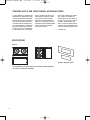
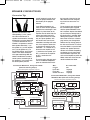
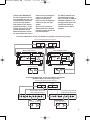
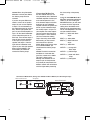
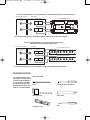
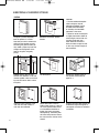
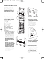
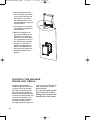
JBLP1948-AAS88 OM
5/26/05
3:58 PM
Page 1
®
®
AAS SERIES
AAS88
OWNER’S GUIDE
JBLP1948-AAS88 OM
5/26/05
3:58 PM
Page 2
THANK YOU FOR CHOOSING AUDIOACCESS
In 1987, Audioaccess pioneered the
development of whole-house audio
systems that combined superlative
audio performance with a proprietary
easy-to-use keypad system. With
the introduction of the AAS Series
of in-wall loudspeakers, Audioaccess
expands its product line to include
one of the most critical components
in any audio system – the speaker.
We are confident that when combined with our controllers, amplifiers and touchscreen keypads,
AAS Series in-wall loudspeakers
will be an essential part of a complete high-quality distributed-audio
system that will be enjoyed for
many years to come.
Please take a moment to register
your product on our Web site,
www.audioaccess.com. Doing so
enables us to keep you posted on
our latest advancements, and
helps us to better understand our
customers and build products that
meet their needs and expectations.
– Audioaccess
INCLUDED
AAS88
Template and paint shield.
One loudspeaker with grille. Logo to be attached to grille depending
on vertical or horizontal installation.
2
JBLP1948-AAS88 OM
5/26/05
3:58 PM
Page 3
SPEAKER PLACEMENT
Low-frequency sounds are
normally omnidirectional, meaning
the listener can’t tell where they
are generated from. However,
frequencies between 75Hz and
150Hz can be localized, especially
at higher volume levels. Positioning your subwoofer as recommended will provide the most
natural soundstage and imaging
from your loudspeaker system.
It is generally recommended that
the speaker be installed so that
the bottom of the speaker is
approximately 12" from the floor.
This is to help with the low-frequency loading (bass reinforcement). This also helps hide the
speaker in a less visible place.
In special circumstances, it is
acceptable to install the speaker
at any height on a wall.
It is generally recommended that
you install your AAS88 in-wall
subwoofer along the same wall as
the front loudspeakers. The AAS88
subwoofer is not video-shielded
and should not be placed near a
video display. Installing the AAS88
near a corner will tend to maximize low-frequency output. Be
cautious when installing in a corner, to avoid a “boomy” sound.
Also take into consideration any
unusual features of the room,
such as an alcove, which may
tend to create a localized node
that may affect bass response in
that area of the room.
Remember that these are just
guidelines. Since every listening
room is different, Audioaccess
strongly recommends experimenting with the positioning of your
subwoofer prior to cutting the
wall to obtain the most pleasing
results in your room. One technique that can help you find the
ideal subwoofer location is to
temporarily borrow a stand-alone
subwoofer and place it near the
main listening location. Then
move around the room and determine where you hear the most
pleasing bass performance. This
would then be the ideal location
for the subwoofer.
When using two AAS88 in-wall
subwoofers, you may need to be
concerned about phase, as the
sound waves may cancel each
other out. If bass response seems
low, try inverting the polarity on
one subwoofer – i.e., connect the
(+) terminal on the amplifier to
the (–) terminal on the speaker,
and the (–) terminal on the amplifier to the (+) terminal on the
speaker.
3
JBLP1948-AAS88 OM
5/26/05
3:58 PM
Page 4
SPEAKER CONNECTIONS
Connection Tips
Speakers and electronics have
corresponding (+) and (–) terminals. Most manufacturers of
speakers and electronics, including
Audioaccess, use red to denote the
(+) terminal and black for the (–)
terminal. It is important to connect
both speakers identically: (+) on
the speaker to (+) on the amplifier
and (–) on the speaker to (–) on
the amplifier. Wiring “out of phase”
results in thin sound, weak bass
and a poor stereo image. With the
advent of multichannel surround
sound systems, connecting all of
the speakers in your system with
the correct polarity remains
equally important in order to preserve the proper ambience and
directionality of the program
material.
the bare end of the wire into the
hole. Release the tab and gently
tug the wire to ensure that it is
secure.
If two AAS88 subwoofers are
used, the wires for both speakers
should be the same length. If one
speaker is placed closer to the
amplifier than the other, hide the
excess wire behind the wall. If
bass response seems low, there
may be a phase problem, with
the sound waves from the two
subwoofers canceling each other
out. If bass response seems low,
try inverting the polarity on one
subwoofer – i.e., connect the (+)
terminal on the amplifier to the
(–) terminal on the speaker, and
the (–) terminal on the amplifier
to the (+) terminal on the
speaker.
To use the spring-clip-type terminals on the AAS88 loudspeaker,
press the colored tab and insert
To use the push-type terminals on
the connections panel supplied
with the optional AAS88BB “back
box” enclosure, depress the colored
cap until the pass-through hole in
the binding post is revealed. While
holding the cap down, insert the
bare end of the wire, or a banana
plug, into the pass-through hole.
Release the cap and tug gently on
the wire to ensure that it is secure.
Connection Method #1, Using One AAS88
(Remove Shorting Straps)
Receiver/Amplifier Speaker Outputs
Left
–
Right
+
–
+
Since the AAS88 is a passive loudspeaker, only speaker-level connections are available. Depending
on whether you are using a dedicated subwoofer amplifier or your
main receiver/amplifier to power the
AAS88, select one of the two connection methods that follow.
Wire
Length
Up to 20 ft.
Up to 50 ft.
Greater than 50 ft.
Recommended
Size
16-gauge
14-gauge
12-gauge
Connection Method #1, Using One AAS88
With Back Box (Remove Shorting Straps)
Receiver/Amplifier Speaker Outputs
Rear of AAS88
BLK
+ IN 1 –
GRN
J2
J1
AAS88
L3
L2
Right
+
–
+
C2
C1
®
C3
C4
L4
+ IN 2 –
BLK
+ OUT 2 –
L1
+ OUT 1 –
Left
–
YEL/BLK
YEL
WHT/BLK
WHT
ORG/BLK
ORG
GRE/BLK
GRE
ORN
–
+
INPUT 1
Front Left Speaker
–
+
Front Right Speaker
–
+
+
INPUT 2
Front Left Speaker
–
4
–
–
+
OUTPUT 1
–
+
OUTPUT 2
Connections Panel
of AAS88 Back Box
+
Front Right Speaker
–
+
JBLP1948-AAS88 OM
5/26/05
3:58 PM
Page 5
terminals to the corresponding
terminals on your front left
speaker, and the Output 2
terminals to the corresponding
terminals on your front right
speaker.
You may wish to mount the
AAS88 horizontally to preserve
the stereo image of the left and
right low frequencies.
Connection Method #1
Use this method when you are
using the AAS88 with your main
receiver/amplifier. Connect the
main left and right speakerlevel outputs on your receiver/
amplifier to the Input 1 (for left
channel) and Input 2 (for right
channel) connectors on the
AAS88 loudspeaker or connection panel. Connect the Output 1
The AAS88’s onboard crossover feeds the low-passed
signal (2nd order at 100Hz) to
the AAS88 subwoofers, and
the high-passed signal to the
speaker-level outputs for
connection to the satellite
speakers.
Connection Method #1, Using Two AAS88 Loudspeakers (Use Shorting Straps)
Receiver/Amplifier Speaker Outputs
Right
Left
–
+
–
BLK
+ OUT 1 –
BLK
GRN
J2
®
C3
L3
J1
®
C3
L3
C4
L4
+ IN 2 –
+ IN 2 –
+ OUT 2 –
C2
C1
AAS88
C4
L4
BLK
L2
L1
C2
C1
AAS88
GRN
J1
+ IN 1 –
+ IN 1 –
L2
L1
J2
+ OUT 1 –
Rear of Right AAS88
BLK
ORN
+ OUT 2 –
Rear of Left AAS88
+
ORN
Front Right Speaker
Front Left Speaker
–
–
+
+
Connection Method #1, Using Two AAS88 Loudspeakers
With Back Boxes (Use Shorting Straps)
Receiver/Amplifier Speaker Outputs
Left
–
Right
+
–
+
Connections Panel of
Left AAS88 Back Box
YEL/BLK
YEL
–
+
INPUT 1
WHT/BLK
–
WHT
+
INPUT 2
ORG/BLK
ORG
GRE/BLK
–
+
OUTPUT 1
Front Left Speaker
–
GRE
–
+
OUTPUT 2
+
Connections Panel of
Right AAS88 Back Box
YEL/BLK
YEL
–
+
INPUT 1
WHT/BLK
–
WHT
ORG/BLK
+
INPUT 2
ORG
–
+
OUTPUT 1
GRE/BLK
GRE
–
+
OUTPUT 2
Front Right Speaker
–
+
5
JBLP1948-AAS88 OM
5/26/05
3:58 PM
NOTE: When using Connection
Method #1 with only one AAS88,
the shorting straps must be
removed.
Page 6
that is occurring at the preamp
stage.
Connection Method #2
Use this method when you are
using the AAS88 with a dedicated
subwoofer amplifier. Connect your
main receiver/processor’s linelevel subwoofer output to the linelevel input on your subwoofer
amplifier. Connect the speaker terminals on your subwoofer amplifier to either Input 1 or Input 2. If
your amplifier has stereo outputs,
you may connect one channel to
each of Inputs 1 and 2. However,
you must remove the shorting
straps when using stereo mode.
Alternatively, you may connect
each channel to a separate
AAS88. When using only one input
on an individual AAS88, you
should leave the shorting straps
in place.
NOTE: The built-in network on
the AAS88 is a 2nd-order lowpass filter, crossed over at 100Hz.
This filter is always active.
Although the subwoofer or LFE
output on your receiver/processor
may already be crossed over, the
AAS88’s network will not interfere
with the higher-order processing
If you are using two AAS88 subwoofers, connect the left speaker
outputs on your receiver/amplifier
to Input 1 on one subwoofer (or
the connections panel on its back
box), and the right speaker outputs on your receiver/amplifier to
Input 1 on the second subwoofer
(or the connections panel on its
back box). Then connect Output 1
from the left-channel subwoofer
to the inputs on your main left
speaker, and Output 1 from the
right-channel subwoofer to the
inputs on your main right speaker.
When using the AAS88 in this
mono mode, you should not
remove the shorting straps.
Using the AAS88BB Back Box
Whichever connection method you
choose, if you are installing the
AAS88BB back box, you will need
to connect all of the eight wires
coming out of the bottom of the
back box to the appropriate terminals on the loudspeaker. The wires
are color-coded as follows:
INPUT 1 (–): Yellow with black
stripe
INPUT 1 (+): Solid yellow
INPUT 2 (–): White with black
stripe
INPUT 2 (+): Solid white
OUTPUT 1 (–): Orange with
black stripe
OUTPUT 1 (+): Solid orange
OUTPUT 2 (–): Green with black
stripe
OUTPUT 2 (+): Solid green
Connection Method #2, Using One AAS88 in Mono Mode (Use Shorting Straps)
Amplifier
+
+ IN 1 –
–
L1
J2
J1
AAS88
L3
L2
C2
C1
®
C3
C4
L4
+ IN 2 –
BLK
ORN
6
+ OUT 1 –
Rear of AAS88**
Speaker-Level
Outputs
+ OUT 2 –
Line-Level
Input
BLK
Subwoofer
Out
GRN
Receiver/Processor
JBLP1948-AAS88 OM
5/26/05
3:58 PM
Page 7
Connection Method #2, Using One AAS88 in Stereo Mode (Remove Shorting Straps)
Amplifier
Receiver/Processor
Line-Level
Inputs
Rear of AAS88**
Speaker-Level
Outputs
J2
Right
Right
J1
AAS88
®
C3
L3
+
Right
C2
C1
C4
L4
+ IN 2 –
–
L2
L1
Left
+ OUT 2 –
Left
Left
+ OUT 1 –
BLK
+
GRN
–
+ IN 1 –
Subwoofer or
Main Amp
Out
BLK
ORN
** Use corresponding inputs on AAS88BB connections panel when installed with back box.
Connection Method #2, Using Two AAS88 Loudspeakers
With Back Boxes (Use Shorting Straps)
Receiver/Processor
Amplifier
Subwoofer or
Main Amp
Out
Line-Level
Inputs
Left
Left
YEL/BLK
–
+
Left
Right
YEL
–
+
INPUT 1
WHT/BLK
–
WHT
+
INPUT 2
ORG/BLK
ORG
–
+
OUTPUT 1
GRE/BLK
GRE
–
+
OUTPUT 2
Right AAS88 Back Box***
–
Right
Left AAS88 Back Box***
Speaker-Level
Outputs
+
Right
YEL/BLK
YEL
–
+
INPUT 1
WHT/BLK
–
WHT
+
INPUT 2
ORG/BLK
ORG
–
+
OUTPUT 1
GRE/BLK
GRE
–
+
OUTPUT 2
*** Use corresponding inputs on rear of AAS88 speaker when installed without back box.
INSTALLATION
The Audioaccess AAS Series in- Tools Needed
wall speakers were designed to
be easily installed. However, if
you are unsure of your ability
to properly install these loudPencil
speakers, please contact your
dealer or a qualified installer.
Measuring tape
Carpenter’s level
Phillips-head #2 screwdriver
Utility knife
Awl
7
JBLP1948-AAS88 OM
5/26/05
3:58 PM
Page 8
EXISTING CONSTRUCTION
AAS88
Level
Template
The grille is packed separately
from the speaker. If at some
later date you wish to remove the
grille from the speaker, to avoid
scratching the grille or baffle you
may unfold a paper clip, insert the
straight end through one of the
holes in the grille, and gently
pull up.
Determine the correct speaker
location.
NOTES:
• Use the cardboard template
when cutting the drywall.
Although the AAS88 may be
oriented either horizontally
or vertically, the installation
procedure is the same.
• Please be aware the template
is slightly oversized to allow for
some margin of error when cutting with the drywall saw –
there should be no need to
allow for further margin of error
as this may risk the integrity of
the installation.
1/2"
1/2"
1/2"
8
NOTE: Always allow at least
one-half inch between a wall stud
and the speaker cutout, or the locking tabs will not be able to swivel
into place.
Cut the drywall.
Connect the speaker wires to
the speaker as described on
pages 4–7.
Place the frame assembly in the
wall until the frame surface is
flush with the wallboard.
Screw down each of the ten
Phillips-head screws. It is best to
use a low-speed cordless driver
or a handheld screwdriver to
tighten the screws to prevent
overtightening. The locking tabs
will swivel into place and secure
the unit to the rear surface of the
drywall.
Replace the metal grille. Attach the
Audioaccess logo to the grille to
correspond to vertical or horizontal
installation.
JBLP1948-AAS88 OM
5/26/05
3:58 PM
Page 9
NEW CONSTRUCTION
You may either purchase the
optional AAS88 back box kit, or
you may install the speaker after
the wallboard has been installed
by following the instructions for
existing construction on page 8.
See
Detail A
L-Brackets
INSTRUCTIONS FOR
INSTALLING THE AAS88
USING THE AAS88BB BACK
BOX KIT
The AAS88BB enclosure “back
box” is optional. If desired, it is
installed during new construction
before the wallboard is installed.
Detail B
See
Detail B
Centering Bar
Included With the
AAS88BB:
(4) L-brackets
(8) #10 32 x 1" screws
(8) #10 split washers
(8) #10 flat washers
(8) #8 x 3/4" woofer screws
(2) wood centering bars
(4) #10 32 x 1-1/2" flat-head
screws
3. Fit the enclosure into the wall.
The bottom edge of the bottom
L-brackets will rest against the
baseboard 2 x 4.
At this time, make note of
adjustments necessary to
square the enclosure into
the wall (see Detail C).
Centering Bar
Installation:
1. Install the two centering bars as
shown in Detail B in the drawings. The centering bars are for
setting the depth of the enclosure. They also help locate the
left/right position of the enclosure as they can be mounted
into the studs at the left and
right to hold the enclosure in
the correct location before final
mounting.
2. Install the four L-brackets to the
four corners of the enclosure.
Each of the eight screws should
have both the split washer and
flat washer installed; the split
washer goes on first. Leave the
screws a half-turn loose at first
to allow for adjustment later
(see Detail A). Do not screw the
L-brackets to the wall studs at
this time (see step 6).
Detail C
See
Detail C
L-Brackets
Detail A
4. After refitting and tightening the
L-brackets into the enclosure
(but not the wall studs yet), fit
the enclosure into the wall once
again.
5. At this time, you may want to
screw through each side of the
wood centering bars to mount
the enclosure to the studs. This
will help hold the enclosure in
position before the L-brackets
are mounted to the studs.
6. Screw the L-brackets into the
studs.
9
JBLP1948-AAS88 OM
5/26/05
3:58 PM
Page 10
7. Remove the wood centering
bars and replace the flat-head
screws into the holes left over
(the holes left in the cabinet
face underneath the bars are
also counterbored to accept the
flat-head screws).
8. The enclosure is now installed
and ready for the wallboard to
be installed over it.
See
Detail A
9. Make the connections from
your receiver/amplifier to the
AAS88 back box connections
panel, and to any other speakers as appropriate for your system, following the instructions
on pages 4–7. Connect the
eight wires hanging from the
bottom of the AAS88BB back
box to the correct terminals on
the AAS88 loudspeaker. See
pages 6–7.
PAINTING THE SPEAKER
FRAME AND GRILLE
Audioaccess AAS Series loudspeakers can be painted to match
any décor. If you wish to change
their color, the satin finish on the
grille and frame will function as a
primer coat. Before painting, install
the plastic paint shield securely into
the recess in the baffle. This will
protect the speaker components
and baffle from paint residue.
Use a high-quality spray paint, and
10
apply a thin coat of color. Paint the
grille separately from the baffle
before installing it.
Be certain the grille perforations remain free of paint.
Filling them with paint will
diminish the sound quality.
JBLP1948-AAS88 OM
5/26/05
3:58 PM
Page 11
TROUBLESHOOTING
If there is no sound from
any of the speakers:
If there is low (or no) bass
output:
• Check that receiver/amplifier
is on and a source is playing.
• Check all wires and connections
between receiver/amplifier and
speakers. Make sure all wires are
connected. Make sure none of the
speaker wires are frayed, cut, punctured or touching each other.
• Review proper operation of your
receiver/amplifier.
• Make sure the connections to the
“Speaker Inputs” have the correct
polarity (+ and –). If you are using
two AAS88 subwoofers, try inverting
the polarity on one subwoofer as
described on page 4.
• Consider adding a separate power
amplifier to drive the AAS88 subwoofer.
• In Dolby* Digital or DTS® modes,
make sure your receiver/processor
is correctly configured. When using a
power amplifier with your AAS88
subwoofer, make sure the subwoofer output of the receiver/
processor has been enabled. See
your receiver/ processor’s owner’s
manual for further information on
correct speaker configuration in
Dolby Digital, DTS and other
surround sound modes.
If there is no sound coming
from one speaker:
• Check the “Balance” control on
your receiver/amplifier.
• Check all wires and connections
between receiver/amplifier and
speakers. Make sure all wires are
connected. Make sure none of the
speaker wires are frayed, cut, punctured or touching each other. In multichannel applications, make sure
that your receiver/processor has
been configured to enable all channels that you are using.
If the system plays at low
volumes but shuts off as
volume is increased:
• Check all wires and connections
between receiver/amplifier and
speakers. Make sure all wires are
connected. Make sure none of the
speaker wires are frayed, cut, punctured or touching each other.
• If more than one pair of main
speakers is being used, check the
minimum-impedance requirements
of your receiver/amplifier.
11
JBLP1948-AAS88 OM
5/26/05
3:58 PM
Page 12
SPECIFICATIONS
AAS88
Frequency Response
Maximum Recommended Amplifier Power†
Impedance
Sensitivity
Crossover Frequency
Woofer
Plate Size (W x H)
Mounting Cutout Size (W x H)
Mounting Depth
Weight per Speaker
30Hz – 100Hz (–6dB)
250 Watts per channel
8 Ohms nominal per woofer
94dB (2.83V/1m), both woofers driven
100Hz, 2nd order
Dual 8" polymer-coated aluminum cones w/rubber surrounds
11-7/16" x 20-7/16" (290mm x 518mm)
10" x 18-5/16" (254mm x 465mm)
3-7/8" (98mm)
17 lb (7.7kg)
All features and specifications are subject to change without notice.
†The maximum recommended amplifier power rating will ensure proper system headroom to allow for
occasional peaks. We do not recommend sustained operation at these maximum power levels.
* Dolby is a registered trademark of Dolby Laboratories.
DTS is a registered trademark of Digital Theater Systems, Inc.
Declaration of Conformity
We, Harman Consumer Group International
2, route de Tours
72500 Chateau du Loir
France
declare in own responsibility that the product
described in this owner’s manual is in compliance
with technical standards:
EN 61000-6-3:2001
EN 61000-6-1:2001
Laurent Rault
Harman Consumer Group International
Chateau du Loir, France 5/05
®
AAS SERIES
Audioaccess
250 Crossways Park Drive, Woodbury, NY 11797 USA
8500 Balboa Boulevard, Northridge, CA 91329 USA
888.691.4171 (USA only) www.audioaccess.com
MODEL: AAS88
NOTE: For new-construction applications, be sure
to purchase the AAS88BB back box kit.
OWNER’S GUIDE
© 2005 Harman International Industries, Incorporated.
All rights reserved.
DESIGN GOAL: Combine the superior performance of traditional
Audioaccess loudspeakers with the convenience of in-wall installation.
WOOFER TYPE:
Audioaccess is a trademark of Harman International
Industries, Incorporated, registered in the United States
and/or other countries.
Polymer-coated aluminum cone with rubber surround
CROSSOVER NETWORK:
Straight-Line Signal Path™ (SSP™)
PROFESSIONAL REFERENCE:
Part No.406-000-05236
Studio Monitor
®
![PS manual[P].qXp2](http://vs1.manualzilla.com/store/data/005858764_1-0e0b40902f5a565498b3e3a041c7e706-150x150.png)