1
Bull NovaScale 5000 Series
User’s Guide
ORDER REFERENCE
86 A1 89EF 02
Bull NovaScale 5000 Series
User’s Guide
Hardware
January 2004
BULL CEDOC
357 AVENUE PATTON
B.P.20845
49008 ANGERS CEDEX 01
FRANCE
ORDER REFERENCE
86 A1 89EF 02
The following copyright notice protects this book under the Copyright laws of the United States of America
and other countries which prohibit such actions as, but not limited to, copying, distributing, modifying, and
making derivative works.
Copyright
Bull S.A. 1992, 2004
Printed in France
Suggestions and criticisms concerning the form, content, and presentation of
this book are invited. A form is provided at the end of this book for this purpose.
To order additional copies of this book or other Bull Technical Publications, you
are invited to use the Ordering Form also provided at the end of this book.
Trademarks and Acknowledgements
We acknowledge the right of proprietors of trademarks mentioned in this book.
AIX is a registered trademark of International Business Machines Corporation, and is being used under
licence.
UNIX is a registered trademark in the United States of America and other countries licensed exclusively through
the Open Group.
Linux is a registered trademark of Linus Torvalds.
The information in this document is subject to change without notice. Bull will not be liable for errors contained
herein, or for incidental or consequential damages in connection with the use of this material.
Table of Contents
List of Figures . . . . . . . . . . . . . . . . . . . . . . . . . . . . . . . . . . . . . . . . . . . . . . . . . . . . . . . . . . .
List of Tables . . . . . . . . . . . . . . . . . . . . . . . . . . . . . . . . . . . . . . . . . . . . . . . . . . . . . . . . . . . .
vii
x
Overview . . . . . . . . . . . . . . . . . . . . . . . . . . . . . . . . . . . . . . . . . . . . . . . . . . . . . . . . . . . . . . .
Intended Readers . . . . . . . . . . . . . . . . . . . . . . . . . . . . . . . . . . . . . . . . . . . . . . . . . . . . . . . .
Highlighting . . . . . . . . . . . . . . . . . . . . . . . . . . . . . . . . . . . . . . . . . . . . . . . . . . . . . . . . . . . . .
Related Publications . . . . . . . . . . . . . . . . . . . . . . . . . . . . . . . . . . . . . . . . . . . . . . . . . . . . .
Regulatory Specifications and Disclaimers . . . . . . . . . . . . . . . . . . . . . . . . . . . . . . . . . .
Definition of Safety Notices . . . . . . . . . . . . . . . . . . . . . . . . . . . . . . . . . . . . . . . . . . . . . . . .
Electrical Safety . . . . . . . . . . . . . . . . . . . . . . . . . . . . . . . . . . . . . . . . . . . . . . . . . . . . . . . . .
Laser Safety Information . . . . . . . . . . . . . . . . . . . . . . . . . . . . . . . . . . . . . . . . . . . . . . . . . .
Data Integrity and Verification . . . . . . . . . . . . . . . . . . . . . . . . . . . . . . . . . . . . . . . . . . . . .
AZERTY/QWERTY Keyboard Lookup Table . . . . . . . . . . . . . . . . . . . . . . . . . . . . . . . . .
Administrator’s Memorandum . . . . . . . . . . . . . . . . . . . . . . . . . . . . . . . . . . . . . . . . . . . . .
Operator’s Memorandum . . . . . . . . . . . . . . . . . . . . . . . . . . . . . . . . . . . . . . . . . . . . . . . . .
xii
xii
xii
xiii
xiv
xvi
xvi
xvii
xvii
xviii
xx
xxii
Chapter 1. Introducing Bull NovaScale 5000 Series Servers . . . . . . . . . . . . . . . .
Bull NovaScale Server Overview . . . . . . . . . . . . . . . . . . . . . . . . . . . . . . . . . . . . . . . . . . .
Getting to Know Bull NovaScale Servers . . . . . . . . . . . . . . . . . . . . . . . . . . . . . . . . . . . .
NovaScale 5080 Server . . . . . . . . . . . . . . . . . . . . . . . . . . . . . . . . . . . . . . . . . . . . . . . .
NovaScale 5160 Server . . . . . . . . . . . . . . . . . . . . . . . . . . . . . . . . . . . . . . . . . . . . . . . .
Server Components . . . . . . . . . . . . . . . . . . . . . . . . . . . . . . . . . . . . . . . . . . . . . . . . . . . . . .
Central Subsystem (CSS) Module . . . . . . . . . . . . . . . . . . . . . . . . . . . . . . . . . . . . . . .
Console Drawer . . . . . . . . . . . . . . . . . . . . . . . . . . . . . . . . . . . . . . . . . . . . . . . . . . . . . . .
Keyboard / Video / Mouse (KVM) Switch . . . . . . . . . . . . . . . . . . . . . . . . . . . . . . . . . .
SR–0812 Disk Rack . . . . . . . . . . . . . . . . . . . . . . . . . . . . . . . . . . . . . . . . . . . . . . . . . . .
SR–1422 Disk Rack . . . . . . . . . . . . . . . . . . . . . . . . . . . . . . . . . . . . . . . . . . . . . . . . . . .
SJ–0812 Disk Rack Extension . . . . . . . . . . . . . . . . . . . . . . . . . . . . . . . . . . . . . . . . . .
Storeway FDA 1300 Disk Rack . . . . . . . . . . . . . . . . . . . . . . . . . . . . . . . . . . . . . . . . . .
Storeway FDA 2300 Disk Rack . . . . . . . . . . . . . . . . . . . . . . . . . . . . . . . . . . . . . . . . . .
Storeway FDA 1300/2300 Extension Disk Rack . . . . . . . . . . . . . . . . . . . . . . . . . . .
Platform Administration Processor (PAP) Unit . . . . . . . . . . . . . . . . . . . . . . . . . . . . .
Ethernet Hub . . . . . . . . . . . . . . . . . . . . . . . . . . . . . . . . . . . . . . . . . . . . . . . . . . . . . . . . .
Power Distribution Unit (PDU) . . . . . . . . . . . . . . . . . . . . . . . . . . . . . . . . . . . . . . . . . . .
Accessing Server Components . . . . . . . . . . . . . . . . . . . . . . . . . . . . . . . . . . . . . . . . . . . .
Setting up the Console Drawer . . . . . . . . . . . . . . . . . . . . . . . . . . . . . . . . . . . . . . . . . . . .
Accessing the PAP Unit CD–Rom and Diskette Drives . . . . . . . . . . . . . . . . . . . . . . . .
Bull NovaScale Server Resources . . . . . . . . . . . . . . . . . . . . . . . . . . . . . . . . . . . . . . . . .
EFI Utilities . . . . . . . . . . . . . . . . . . . . . . . . . . . . . . . . . . . . . . . . . . . . . . . . . . . . . . . . . . . . .
PAM Software Package . . . . . . . . . . . . . . . . . . . . . . . . . . . . . . . . . . . . . . . . . . . . . . . . . . .
PAP Unit Mirroring and Failover Policy . . . . . . . . . . . . . . . . . . . . . . . . . . . . . . . . . . .
1-1
1-2
1-4
1-4
1-5
1-6
1-6
1-7
1-7
1-8
1-8
1-9
1-9
1-10
1-10
1-11
1-11
1-12
1-13
1-14
1-16
1-17
1-17
1-17
1-18
Chapter 2. Getting Started . . . . . . . . . . . . . . . . . . . . . . . . . . . . . . . . . . . . . . . . . . . . . . .
Connecting to the PAM Web Site . . . . . . . . . . . . . . . . . . . . . . . . . . . . . . . . . . . . . . . . . . .
Local Connection . . . . . . . . . . . . . . . . . . . . . . . . . . . . . . . . . . . . . . . . . . . . . . . . . . . . . .
Remote Connection . . . . . . . . . . . . . . . . . . . . . . . . . . . . . . . . . . . . . . . . . . . . . . . . . . . .
PAM User Interface . . . . . . . . . . . . . . . . . . . . . . . . . . . . . . . . . . . . . . . . . . . . . . . . . . . . . .
Status Pane . . . . . . . . . . . . . . . . . . . . . . . . . . . . . . . . . . . . . . . . . . . . . . . . . . . . . . . . . .
PAM Tree Pane . . . . . . . . . . . . . . . . . . . . . . . . . . . . . . . . . . . . . . . . . . . . . . . . . . . . . . .
Control Pane . . . . . . . . . . . . . . . . . . . . . . . . . . . . . . . . . . . . . . . . . . . . . . . . . . . . . . . . . .
2-1
2-2
2-2
2-3
2-4
2-4
2-4
2-5
Preface
iii
iv
Simultaneous Connection . . . . . . . . . . . . . . . . . . . . . . . . . . . . . . . . . . . . . . . . . . . . . . . . .
Toggling the Local / Integrated Console Display . . . . . . . . . . . . . . . . . . . . . . . . . . . . . .
Setting up Users . . . . . . . . . . . . . . . . . . . . . . . . . . . . . . . . . . . . . . . . . . . . . . . . . . . . . . . . .
Powering Up / Down the Server Domain . . . . . . . . . . . . . . . . . . . . . . . . . . . . . . . . . . . .
Connecting to the Server via the Local / Integrated Console . . . . . . . . . . . . . . . . . . .
Connecting to the Server via the Enterprise LAN . . . . . . . . . . . . . . . . . . . . . . . . . . . . .
Connecting to the Server via the Web . . . . . . . . . . . . . . . . . . . . . . . . . . . . . . . . . . . . . .
2-6
2-6
2-7
2-8
2-10
2-11
2-13
Chapter 3. Managing the Server Domain . . . . . . . . . . . . . . . . . . . . . . . . . . . . . . . . . .
Introducing PAM Domain Management Tools . . . . . . . . . . . . . . . . . . . . . . . . . . . . . . . .
Powering ON the Domain . . . . . . . . . . . . . . . . . . . . . . . . . . . . . . . . . . . . . . . . . . . . . . . . .
Powering OFF the Domain . . . . . . . . . . . . . . . . . . . . . . . . . . . . . . . . . . . . . . . . . . . . . . . .
Performing a Domain Force Power OFF . . . . . . . . . . . . . . . . . . . . . . . . . . . . . . . . . . . .
Performing a Manual Domain Reset . . . . . . . . . . . . . . . . . . . . . . . . . . . . . . . . . . . . . . . .
Performing a Domain Memory Dump . . . . . . . . . . . . . . . . . . . . . . . . . . . . . . . . . . . . . . .
Viewing Domain Functional Status . . . . . . . . . . . . . . . . . . . . . . . . . . . . . . . . . . . . . . . . .
Viewing Power Logs . . . . . . . . . . . . . . . . . . . . . . . . . . . . . . . . . . . . . . . . . . . . . . . . . . . . . .
Viewing BIOS Info . . . . . . . . . . . . . . . . . . . . . . . . . . . . . . . . . . . . . . . . . . . . . . . . . . . . . . .
Viewing Domain Hardware Resources . . . . . . . . . . . . . . . . . . . . . . . . . . . . . . . . . . . . . .
What To Do if an Incident Occurs . . . . . . . . . . . . . . . . . . . . . . . . . . . . . . . . . . . . . . . . . .
3-1
3-2
3-3
3-4
3-5
3-6
3-7
3-8
3-8
3-8
3-9
3-11
Chapter 4. Monitoring the Server . . . . . . . . . . . . . . . . . . . . . . . . . . . . . . . . . . . . . . . . .
Introducing Monitoring Tools . . . . . . . . . . . . . . . . . . . . . . . . . . . . . . . . . . . . . . . . . . . . . . .
Status Pane . . . . . . . . . . . . . . . . . . . . . . . . . . . . . . . . . . . . . . . . . . . . . . . . . . . . . . . . . .
PAM Tree Pane . . . . . . . . . . . . . . . . . . . . . . . . . . . . . . . . . . . . . . . . . . . . . . . . . . . . . . .
Viewing PAM Web Site User Information . . . . . . . . . . . . . . . . . . . . . . . . . . . . . . . . . . . .
Viewing PAM Version Information . . . . . . . . . . . . . . . . . . . . . . . . . . . . . . . . . . . . . . . . . .
Viewing Server Hardware Status . . . . . . . . . . . . . . . . . . . . . . . . . . . . . . . . . . . . . . . . . . .
Displaying Detailed Hardware Information . . . . . . . . . . . . . . . . . . . . . . . . . . . . . . . . . . .
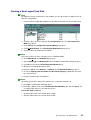
Using the Hardware Search Engine . . . . . . . . . . . . . . . . . . . . . . . . . . . . . . . . . . . . . . . .
Excluding / Including Hardware Elements . . . . . . . . . . . . . . . . . . . . . . . . . . . . . . . . . . .
Viewing and Managing PAM Event Messages and History Files . . . . . . . . . . . . . . . .
Understanding Event Message and History Severity Levels . . . . . . . . . . . . . . . . . . .
Consulting Event Messages, the Hardware Faults List, and History Files . . . . . . .
Viewing and Acknowledging PAM Web Event Messages . . . . . . . . . . . . . . . . . . . .
Displaying the Faults List . . . . . . . . . . . . . . . . . . . . . . . . . . . . . . . . . . . . . . . . . . . . . . .
Viewing, Archiving, and Deleting History Files . . . . . . . . . . . . . . . . . . . . . . . . . . . . .
Viewing E–mailed Event Messages . . . . . . . . . . . . . . . . . . . . . . . . . . . . . . . . . . . . . .
Sorting and Locating Messages . . . . . . . . . . . . . . . . . . . . . . . . . . . . . . . . . . . . . . . . . . . .
What to Do if an Incident Occurs . . . . . . . . . . . . . . . . . . . . . . . . . . . . . . . . . . . . . . . . . . .
Investigating Incidents . . . . . . . . . . . . . . . . . . . . . . . . . . . . . . . . . . . . . . . . . . . . . . . . . . . .
Dealing with Incidents . . . . . . . . . . . . . . . . . . . . . . . . . . . . . . . . . . . . . . . . . . . . . . . . . . . .
4-1
4-2
4-3
4-4
4-7
4-7
4-8
4-9
4-16
4-17
4-20
4-20
4-21
4-22
4-22
4-23
4-23
4-24
4-25
4-25
4-27
Chapter 5. Tips and Features for Administrators . . . . . . . . . . . . . . . . . . . . . . . . . .
Setting up Server Users . . . . . . . . . . . . . . . . . . . . . . . . . . . . . . . . . . . . . . . . . . . . . . . . . .
Configuring SR–0812 / SR–1422 SCSI Data Disks . . . . . . . . . . . . . . . . . . . . . . . . . . .
Configuring Storeway FDA 1300/2300 Data Disks . . . . . . . . . . . . . . . . . . . . . . . . . . . .
Using the EFI Boot Manager . . . . . . . . . . . . . . . . . . . . . . . . . . . . . . . . . . . . . . . . . . . . . .
Using the EFI Shell . . . . . . . . . . . . . . . . . . . . . . . . . . . . . . . . . . . . . . . . . . . . . . . . . . . . . .
EFI Network Setup and Configuration . . . . . . . . . . . . . . . . . . . . . . . . . . . . . . . . . . . . . .
Setting up PAP Unit Users . . . . . . . . . . . . . . . . . . . . . . . . . . . . . . . . . . . . . . . . . . . . . . . .
Modifying Customer Information . . . . . . . . . . . . . . . . . . . . . . . . . . . . . . . . . . . . . . . . . . .
Configuring PAM Autocall Parameters . . . . . . . . . . . . . . . . . . . . . . . . . . . . . . . . . . . . . .
Customizing PAM Settings . . . . . . . . . . . . . . . . . . . . . . . . . . . . . . . . . . . . . . . . . . . . . . . .
Deploying a New PAM Release . . . . . . . . . . . . . . . . . . . . . . . . . . . . . . . . . . . . . . . . . . . .
5-1
5-2
5-3
5-6
5-8
5-11
5-16
5-18
5-20
5-21
5-22
5-23
User’s Guide
Activating a PAM Version . . . . . . . . . . . . . . . . . . . . . . . . . . . . . . . . . . . . . . . . . . . . . . . . .
Customizing the PAM Event Messaging System . . . . . . . . . . . . . . . . . . . . . . . . . . . . .
Setting up Event Subscriptions . . . . . . . . . . . . . . . . . . . . . . . . . . . . . . . . . . . . . . . . . . . .
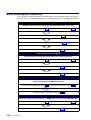
Event Subscription Flowcharts . . . . . . . . . . . . . . . . . . . . . . . . . . . . . . . . . . . . . . . . . . . . .
Creating an E–Mail Server . . . . . . . . . . . . . . . . . . . . . . . . . . . . . . . . . . . . . . . . . . . . . . . .
Editing E–mail Server Attributes . . . . . . . . . . . . . . . . . . . . . . . . . . . . . . . . . . . . . . . . . . .
Deleting an E–mail Server . . . . . . . . . . . . . . . . . . . . . . . . . . . . . . . . . . . . . . . . . . . . . . . .
Creating an E–mail Account . . . . . . . . . . . . . . . . . . . . . . . . . . . . . . . . . . . . . . . . . . . . . . .
Editing E–mail Account Attributes . . . . . . . . . . . . . . . . . . . . . . . . . . . . . . . . . . . . . . . . . .
Deleting an E–mail Account . . . . . . . . . . . . . . . . . . . . . . . . . . . . . . . . . . . . . . . . . . . . . . .
Creating a User History . . . . . . . . . . . . . . . . . . . . . . . . . . . . . . . . . . . . . . . . . . . . . . . . . . .
Editing History Parameters . . . . . . . . . . . . . . . . . . . . . . . . . . . . . . . . . . . . . . . . . . . . . . . .
Deleting a User History . . . . . . . . . . . . . . . . . . . . . . . . . . . . . . . . . . . . . . . . . . . . . . . . . . .
Enabling / Disabling Event Channels . . . . . . . . . . . . . . . . . . . . . . . . . . . . . . . . . . . . . . .
Creating an Event Subscription . . . . . . . . . . . . . . . . . . . . . . . . . . . . . . . . . . . . . . . . . . . .
Editing Event Subscription Attributes . . . . . . . . . . . . . . . . . . . . . . . . . . . . . . . . . . . . . . .
Deleting an Event Subscription . . . . . . . . . . . . . . . . . . . . . . . . . . . . . . . . . . . . . . . . . . . .
Understanding Event Message Filtering Criteria . . . . . . . . . . . . . . . . . . . . . . . . . . . . . .
Standard Event Message Filtering Criteria . . . . . . . . . . . . . . . . . . . . . . . . . . . . . . . . . .
Advanced Event Message Filtering Criteria . . . . . . . . . . . . . . . . . . . . . . . . . . . . . . . . . .
Preselecting an Event Filter . . . . . . . . . . . . . . . . . . . . . . . . . . . . . . . . . . . . . . . . . . . . . . .
Creating an Event Filter . . . . . . . . . . . . . . . . . . . . . . . . . . . . . . . . . . . . . . . . . . . . . . . . . . .
Editing Event Filter Attributes . . . . . . . . . . . . . . . . . . . . . . . . . . . . . . . . . . . . . . . . . . . . . .
Deleting an Event Filter . . . . . . . . . . . . . . . . . . . . . . . . . . . . . . . . . . . . . . . . . . . . . . . . . . .
5-24
5-26
5-27
5-28
5-29
5-30
5-30
5-31
5-32
5-32
5-33
5-34
5-35
5-36
5-37
5-38
5-38
5-39
5-41
5-44
5-49
5-50
5-51
5-51
Appendix A. Specifications . . . . . . . . . . . . . . . . . . . . . . . . . . . . . . . . . . . . . . . . . . . . .
NovaScale 5080/5160 Server Specifications . . . . . . . . . . . . . . . . . . . . . . . . . . . . . . . . .
A-1
A-1
Appendix B. NovaScale 5080/5160 Server Cabling . . . . . . . . . . . . . . . . . . . . . . . . .
Console Data Cables . . . . . . . . . . . . . . . . . . . . . . . . . . . . . . . . . . . . . . . . . . . . . . . . . . . .
KVM Switch Data Cables (Windows) . . . . . . . . . . . . . . . . . . . . . . . . . . . . . . . . . . . . . . .
KVM Switch Data Cables (Linux) . . . . . . . . . . . . . . . . . . . . . . . . . . . . . . . . . . . . . . . . . .
IOR Data Cables (Windows) . . . . . . . . . . . . . . . . . . . . . . . . . . . . . . . . . . . . . . . . . . . . . .
IOR Data Cables (Linux) . . . . . . . . . . . . . . . . . . . . . . . . . . . . . . . . . . . . . . . . . . . . . . . . .
PAP Unit Data Cables (SR–0812 Disk Rack) . . . . . . . . . . . . . . . . . . . . . . . . . . . . . . .
PAP Unit Data Cables (SR–1422 Disk Rack) . . . . . . . . . . . . . . . . . . . . . . . . . . . . . . . .
PAP Unit Data Cables (Storeway FDA 1300 Disk Rack) . . . . . . . . . . . . . . . . . . . . . .
PAP Unit Data Cables (Storeway FDA 2300 Disk Rack) . . . . . . . . . . . . . . . . . . . . . .
SR–0812 Disk Rack Data Cables . . . . . . . . . . . . . . . . . . . . . . . . . . . . . . . . . . . . . . . . . .
SR–1422 Disk Rack Data Cables . . . . . . . . . . . . . . . . . . . . . . . . . . . . . . . . . . . . . . . . . .
SR–1422 SCSI Disk Rack Dual HBA Data Cables . . . . . . . . . . . . . . . . . . . . . . . . . . .
Storeway FDA 1300 Disk Rack Data Cables . . . . . . . . . . . . . . . . . . . . . . . . . . . . . . . .
Storeway FDA 1300 Extension Disk Rack Data Cables . . . . . . . . . . . . . . . . . . . . . . .
Storeway FDA 1300 Disk Rack Dual HBA Data Cables . . . . . . . . . . . . . . . . . . . . . . .
Storeway FDA 2300 Disk Rack Data Cables . . . . . . . . . . . . . . . . . . . . . . . . . . . . . . . .
Storeway FDA 2300 Disk Rack Dual HBA Data Cables . . . . . . . . . . . . . . . . . . . . . . .
Storeway FDA 2300 Extension Disk Rack Data Cables . . . . . . . . . . . . . . . . . . . . . . .
PMB – PAP Data Cables (SCSI Storage Subsystem) . . . . . . . . . . . . . . . . . . . . . . . . .
PMB – PAP Data Cables (FC Storage Subsystem) . . . . . . . . . . . . . . . . . . . . . . . . . . .
Ethernet Hub Data Cables (Storeway FDA 1300 Disk Rack) . . . . . . . . . . . . . . . . . . .
Ethernet Hub Data Cables (Storeway FDA 2300 Disk Rack) . . . . . . . . . . . . . . . . . . .
Power Cables . . . . . . . . . . . . . . . . . . . . . . . . . . . . . . . . . . . . . . . . . . . . . . . . . . . . . . . . . . .
B-1
B-2
B-3
B-4
B-5
B-6
B-7
B-8
B-9
B-10
B-11
B-12
B-13
B-14
B-15
B-16
B-17
B-18
B-19
B-20
B-20
B-21
B-22
B-23
Preface
v
vi
Appendix C. Error Messages and Recovery Information . . . . . . . . . . . . . . . . . . .
BIOS POST Codes . . . . . . . . . . . . . . . . . . . . . . . . . . . . . . . . . . . . . . . . . . . . . . . . . . . . . .
BIOS Error Messages . . . . . . . . . . . . . . . . . . . . . . . . . . . . . . . . . . . . . . . . . . . . . . . . . . . .
SAL–A POST Codes . . . . . . . . . . . . . . . . . . . . . . . . . . . . . . . . . . . . . . . . . . . . . . . . . . . . .
SAL–B POST Codes . . . . . . . . . . . . . . . . . . . . . . . . . . . . . . . . . . . . . . . . . . . . . . . . . . . . .
SAL–F POST Codes . . . . . . . . . . . . . . . . . . . . . . . . . . . . . . . . . . . . . . . . . . . . . . . . . . . . .
IA–32 POST Codes . . . . . . . . . . . . . . . . . . . . . . . . . . . . . . . . . . . . . . . . . . . . . . . . . . . . . .
DIM Code Checkpoints . . . . . . . . . . . . . . . . . . . . . . . . . . . . . . . . . . . . . . . . . . . . . . . . . . .
PCI Diagnostic POST Codes . . . . . . . . . . . . . . . . . . . . . . . . . . . . . . . . . . . . . . . . . . . . . .
EFI POST Code MAP . . . . . . . . . . . . . . . . . . . . . . . . . . . . . . . . . . . . . . . . . . . . . . . . . . . .
ACPI POST Codes . . . . . . . . . . . . . . . . . . . . . . . . . . . . . . . . . . . . . . . . . . . . . . . . . . . . . . .
Recovery Port 80 POST Codes . . . . . . . . . . . . . . . . . . . . . . . . . . . . . . . . . . . . . . . . . . . .
Runtime POST Codes . . . . . . . . . . . . . . . . . . . . . . . . . . . . . . . . . . . . . . . . . . . . . . . . . . . .
Boot Error Messages . . . . . . . . . . . . . . . . . . . . . . . . . . . . . . . . . . . . . . . . . . . . . . . . . . . . .
Storage Device Error Messages . . . . . . . . . . . . . . . . . . . . . . . . . . . . . . . . . . . . . . . . . . .
System Configuration Error Messages . . . . . . . . . . . . . . . . . . . . . . . . . . . . . . . . . . . . . .
CMOS Error Messages . . . . . . . . . . . . . . . . . . . . . . . . . . . . . . . . . . . . . . . . . . . . . . . . . . .
Miscellaneous Error Messages . . . . . . . . . . . . . . . . . . . . . . . . . . . . . . . . . . . . . . . . . . . .
PAM Message List . . . . . . . . . . . . . . . . . . . . . . . . . . . . . . . . . . . . . . . . . . . . . . . . . . . . . . .
Message Severity Levels . . . . . . . . . . . . . . . . . . . . . . . . . . . . . . . . . . . . . . . . . . . . . . .
String Lengths . . . . . . . . . . . . . . . . . . . . . . . . . . . . . . . . . . . . . . . . . . . . . . . . . . . . . . . .
Registry Keys . . . . . . . . . . . . . . . . . . . . . . . . . . . . . . . . . . . . . . . . . . . . . . . . . . . . . . . . .
C-1
C-1
C-2
C-3
C-8
C-11
C-13
C-23
C-24
C-25
C-25
C-26
C-28
C-29
C-29
C-30
C-31
C-31
C-32
C-41
C-42
C-42
Glossary . . . . . . . . . . . . . . . . . . . . . . . . . . . . . . . . . . . . . . . . . . . . . . . . . . . . . . . . . . . . . . .
G-1
Index . . . . . . . . . . . . . . . . . . . . . . . . . . . . . . . . . . . . . . . . . . . . . . . . . . . . . . . . . . . . . . . . . .
X-1
User’s Guide
List of Figures
Figure 1.
Figure 2.
Figure 3.
Figure 4.
Figure 5.
Figure 6.
Figure 7.
Figure 8.
Figure 9.
Figure 10.
Figure 11.
Figure 12.
Figure 13.
Figure 14.
Figure 15.
Figure 16.
Figure 17.
Figure 18.
Figure 19.
Figure 20.
Figure 21.
Figure 22.
Figure 23.
Figure 24.
Figure 25.
Figure 26.
Figure 27.
Figure 28.
Figure 29.
Figure 30.
Figure 31.
Figure 32.
Figure 33.
Figure 34.
Figure 35.
Figure 36.
Figure 37.
Figure 38.
Figure 39.
Figure 40.
Figure 41.
Figure 42.
Figure 43.
Figure 44.
Figure 45.
Figure 46.
Figure 47.
AZERTY keyboard . . . . . . . . . . . . . . . . . . . . . . . . . . . . . . . . . . . . . . . . . . . . . . . . . . . . . . . . . . .
QWERTY keyboard . . . . . . . . . . . . . . . . . . . . . . . . . . . . . . . . . . . . . . . . . . . . . . . . . . . . . . . . . .
Bull NovaScale Server cabinet . . . . . . . . . . . . . . . . . . . . . . . . . . . . . . . . . . . . . . . . . . . . . . . .
NovaScale 5080 Server components (example) . . . . . . . . . . . . . . . . . . . . . . . . . . . . . . . . .
NovaScale 5160 Server components (example) . . . . . . . . . . . . . . . . . . . . . . . . . . . . . . . . .
CSS module features . . . . . . . . . . . . . . . . . . . . . . . . . . . . . . . . . . . . . . . . . . . . . . . . . . . . . . . .
Console drawer features . . . . . . . . . . . . . . . . . . . . . . . . . . . . . . . . . . . . . . . . . . . . . . . . . . . . .
KVM switch features . . . . . . . . . . . . . . . . . . . . . . . . . . . . . . . . . . . . . . . . . . . . . . . . . . . . . . . . .
SR–0812 SCSI disk rack features . . . . . . . . . . . . . . . . . . . . . . . . . . . . . . . . . . . . . . . . . . . . .
SR–1422 SCSI disk rack features . . . . . . . . . . . . . . . . . . . . . . . . . . . . . . . . . . . . . . . . . . . . .
SJ–0812 SCSI extension disk rack features . . . . . . . . . . . . . . . . . . . . . . . . . . . . . . . . . . . . .
Storeway FDA 1300 disk rack features . . . . . . . . . . . . . . . . . . . . . . . . . . . . . . . . . . . . . . . . .
Storeway FDA 2300 disk rack features . . . . . . . . . . . . . . . . . . . . . . . . . . . . . . . . . . . . . . . . .
Storeway FDA 1300/2300 extension disk rack features . . . . . . . . . . . . . . . . . . . . . . . . . . .
PAP unit features . . . . . . . . . . . . . . . . . . . . . . . . . . . . . . . . . . . . . . . . . . . . . . . . . . . . . . . . . . . .
Ethernet hub features . . . . . . . . . . . . . . . . . . . . . . . . . . . . . . . . . . . . . . . . . . . . . . . . . . . . . . . .
PDU features . . . . . . . . . . . . . . . . . . . . . . . . . . . . . . . . . . . . . . . . . . . . . . . . . . . . . . . . . . . . . . .
Opening the front door . . . . . . . . . . . . . . . . . . . . . . . . . . . . . . . . . . . . . . . . . . . . . . . . . . . . . . .
Lowering the console drawer flap . . . . . . . . . . . . . . . . . . . . . . . . . . . . . . . . . . . . . . . . . . . . . .
Extending the mouse tray . . . . . . . . . . . . . . . . . . . . . . . . . . . . . . . . . . . . . . . . . . . . . . . . . . . .
Positioning the monitor . . . . . . . . . . . . . . . . . . . . . . . . . . . . . . . . . . . . . . . . . . . . . . . . . . . . . . .
Console ready for use . . . . . . . . . . . . . . . . . . . . . . . . . . . . . . . . . . . . . . . . . . . . . . . . . . . . . . . .
Closing the console drawer . . . . . . . . . . . . . . . . . . . . . . . . . . . . . . . . . . . . . . . . . . . . . . . . . . .
PAP Unit CD–Rom and Diskette Drives . . . . . . . . . . . . . . . . . . . . . . . . . . . . . . . . . . . . . . . . .
PAM software deployment . . . . . . . . . . . . . . . . . . . . . . . . . . . . . . . . . . . . . . . . . . . . . . . . . . . .
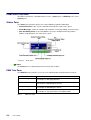
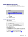
PAM Home Page . . . . . . . . . . . . . . . . . . . . . . . . . . . . . . . . . . . . . . . . . . . . . . . . . . . . . . . . . . . .
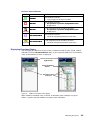
Status pane . . . . . . . . . . . . . . . . . . . . . . . . . . . . . . . . . . . . . . . . . . . . . . . . . . . . . . . . . . . . . . . . .
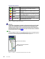
PAM Tree toolbar . . . . . . . . . . . . . . . . . . . . . . . . . . . . . . . . . . . . . . . . . . . . . . . . . . . . . . . . . . . .
PAM Web site session details . . . . . . . . . . . . . . . . . . . . . . . . . . . . . . . . . . . . . . . . . . . . . . . . .
Domain Manager Control pane . . . . . . . . . . . . . . . . . . . . . . . . . . . . . . . . . . . . . . . . . . . . . . . .
PAM Domain Manager Control pane . . . . . . . . . . . . . . . . . . . . . . . . . . . . . . . . . . . . . . . . . . .
Domain Hardware Details page . . . . . . . . . . . . . . . . . . . . . . . . . . . . . . . . . . . . . . . . . . . . . . .
PAM Status pane . . . . . . . . . . . . . . . . . . . . . . . . . . . . . . . . . . . . . . . . . . . . . . . . . . . . . . . . . . . .
PAM Tree hardware presence status display . . . . . . . . . . . . . . . . . . . . . . . . . . . . . . . . . . . .
PAM Tree functional status display . . . . . . . . . . . . . . . . . . . . . . . . . . . . . . . . . . . . . . . . . . . . .
PAM Tree – automatically expanded functional status display . . . . . . . . . . . . . . . . . . . . .
PAM Web Site user information . . . . . . . . . . . . . . . . . . . . . . . . . . . . . . . . . . . . . . . . . . . . . . .
PAM version information . . . . . . . . . . . . . . . . . . . . . . . . . . . . . . . . . . . . . . . . . . . . . . . . . . . . . .
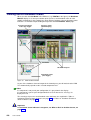
PAM Hardware Monitor . . . . . . . . . . . . . . . . . . . . . . . . . . . . . . . . . . . . . . . . . . . . . . . . . . . . . . .
General Hardware Status page (example) . . . . . . . . . . . . . . . . . . . . . . . . . . . . . . . . . . . . . .
FRU data (example) . . . . . . . . . . . . . . . . . . . . . . . . . . . . . . . . . . . . . . . . . . . . . . . . . . . . . . . . .
Firmware data (example) . . . . . . . . . . . . . . . . . . . . . . . . . . . . . . . . . . . . . . . . . . . . . . . . . . . . .
CSS module thermal zone details . . . . . . . . . . . . . . . . . . . . . . . . . . . . . . . . . . . . . . . . . . . . .
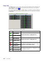
Converter power status details (example) . . . . . . . . . . . . . . . . . . . . . . . . . . . . . . . . . . . . . . .
CSS module power status details . . . . . . . . . . . . . . . . . . . . . . . . . . . . . . . . . . . . . . . . . . . . . .
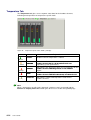
Temperature probe status details (example) . . . . . . . . . . . . . . . . . . . . . . . . . . . . . . . . . . . . .
Fanbox details (example) . . . . . . . . . . . . . . . . . . . . . . . . . . . . . . . . . . . . . . . . . . . . . . . . . . . . .
xviii
xviii
1-2
1-4
1-5
1-6
1-7
1-7
1-8
1-8
1-9
1-9
1-10
1-10
1-11
1-11
1-12
1-13
1-14
1-14
1-14
1-15
1-15
1-16
1-17
2-2
2-4
2-5
2-6
2-8
3-2
3-9
4-3
4-4
4-5
4-6
4-7
4-7
4-8
4-9
4-10
4-11
4-11
4-12
4-13
4-14
4-15
Preface
vii
Figure 48.
Figure 49.
Figure 50.
Figure 51.
Figure 52.
Figure 53.
Figure 54.
Figure 55.
Figure 56.
Figure 57.
Figure 58.
Figure 59.
Figure 60.
Figure 61.
Figure 62.
Figure 63.
Figure 64.
Figure 65.
Figure 66.
Figure 67.
Figure 68.
Figure 69.
Figure 70.
Figure 71.
Figure 72.
Figure 73.
Figure 74.
Figure 75.
Figure 76.
Figure 77.
Figure 78.
Figure 79.
Figure 80.
Figure 81.
Figure 82.
Figure 83.
Figure 84.
Figure 85.
Figure 86.
Figure 87.
Figure 88.
Figure 89.
Figure 90.
Figure 91.
Figure 92.
Figure 93.
Figure 94.
Figure 95.
Figure 96.
viii
IOB jumpers tab . . . . . . . . . . . . . . . . . . . . . . . . . . . . . . . . . . . . . . . . . . . . . . . . . . . . . . . . . . . . .
Hardware Search engine . . . . . . . . . . . . . . . . . . . . . . . . . . . . . . . . . . . . . . . . . . . . . . . . . . . . .
Hardware Search result list (example) . . . . . . . . . . . . . . . . . . . . . . . . . . . . . . . . . . . . . . . . . .
Example Hardware Status page . . . . . . . . . . . . . . . . . . . . . . . . . . . . . . . . . . . . . . . . . . . . . . .
Example Hardware Status page . . . . . . . . . . . . . . . . . . . . . . . . . . . . . . . . . . . . . . . . . . . . . . .
Display Events page . . . . . . . . . . . . . . . . . . . . . . . . . . . . . . . . . . . . . . . . . . . . . . . . . . . . . . . . .
Server PMB . . . . . . . . . . . . . . . . . . . . . . . . . . . . . . . . . . . . . . . . . . . . . . . . . . . . . . . . . . . . . . . .
SR–0812 SCSI disk rack . . . . . . . . . . . . . . . . . . . . . . . . . . . . . . . . . . . . . . . . . . . . . . . . . . . . .
SR–1422 SCSI disk rack . . . . . . . . . . . . . . . . . . . . . . . . . . . . . . . . . . . . . . . . . . . . . . . . . . . . .
Storeway FDA 1300/2300 disk rack . . . . . . . . . . . . . . . . . . . . . . . . . . . . . . . . . . . . . . . . . . . .
Customer Information configuration page . . . . . . . . . . . . . . . . . . . . . . . . . . . . . . . . . . . . . . .
PAM Autocalls configuration page . . . . . . . . . . . . . . . . . . . . . . . . . . . . . . . . . . . . . . . . . . . . .
PAM configuration page . . . . . . . . . . . . . . . . . . . . . . . . . . . . . . . . . . . . . . . . . . . . . . . . . . . . . .
PAM Installation InstallShield Wizard . . . . . . . . . . . . . . . . . . . . . . . . . . . . . . . . . . . . . . . . . . .
PAM Activation InstallShield Wizard . . . . . . . . . . . . . . . . . . . . . . . . . . . . . . . . . . . . . . . . . . . .
PAM event messaging system features . . . . . . . . . . . . . . . . . . . . . . . . . . . . . . . . . . . . . . . . .
E–mail servers configuration page . . . . . . . . . . . . . . . . . . . . . . . . . . . . . . . . . . . . . . . . . . . . .
E–mail accounts configuration page . . . . . . . . . . . . . . . . . . . . . . . . . . . . . . . . . . . . . . . . . . .
New History configuration page . . . . . . . . . . . . . . . . . . . . . . . . . . . . . . . . . . . . . . . . . . . . . . .
Event Channels configuration page . . . . . . . . . . . . . . . . . . . . . . . . . . . . . . . . . . . . . . . . . . . .
New Event Subscription dialog box . . . . . . . . . . . . . . . . . . . . . . . . . . . . . . . . . . . . . . . . . . . .
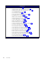
Event message standard filtering criteria chart . . . . . . . . . . . . . . . . . . . . . . . . . . . . . . . . . .
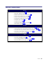
Event message advanced filtering criteria chart . . . . . . . . . . . . . . . . . . . . . . . . . . . . . . . . . .
Filters configuration page . . . . . . . . . . . . . . . . . . . . . . . . . . . . . . . . . . . . . . . . . . . . . . . . . . . . .
New Filter configuration page – standard event message filtering criteria table . . . . . .
New Filter configuration page – advanced event message filtering criteria table . . . . . .
Console data cabling diagram . . . . . . . . . . . . . . . . . . . . . . . . . . . . . . . . . . . . . . . . . . . . . . . . .
KVM switch data cabling diagram (Windows) . . . . . . . . . . . . . . . . . . . . . . . . . . . . . . . . . . . .
KVM data cabling diagram (Linux) . . . . . . . . . . . . . . . . . . . . . . . . . . . . . . . . . . . . . . . . . . . . .
IOR master data cabling diagram (Windows) . . . . . . . . . . . . . . . . . . . . . . . . . . . . . . . . . . . .
IOR master data cabling diagram (Linux) . . . . . . . . . . . . . . . . . . . . . . . . . . . . . . . . . . . . . . .
PAP unit data cabling diagram (SR–0812 SCSI disk rack) . . . . . . . . . . . . . . . . . . . . . . . .
PAP unit data cabling diagram (SR–1422 disk rack) . . . . . . . . . . . . . . . . . . . . . . . . . . . . . .
PAP unit data cabling diagram (Storeway FDA 1300 disk rack) . . . . . . . . . . . . . . . . . . . .
PAP unit data cabling diagram (Storeway FDA 2300 disk rack) . . . . . . . . . . . . . . . . . . . .
SR–0812 disk rack data cabling diagram . . . . . . . . . . . . . . . . . . . . . . . . . . . . . . . . . . . . . . .
SR–1422 disk rack data cabling diagram . . . . . . . . . . . . . . . . . . . . . . . . . . . . . . . . . . . . . . .
SR–1422 SCSI disk rack dual HBA data cabling diagram . . . . . . . . . . . . . . . . . . . . . . . . .
Storeway FDA 1300 disk rack data cabling diagram . . . . . . . . . . . . . . . . . . . . . . . . . . . . . .
Storeway FDA 1300 extension disk rack data cabling diagram . . . . . . . . . . . . . . . . . . . . .
Storeway FDA 1300 disk rack dual HBA data cabling diagram . . . . . . . . . . . . . . . . . . . . .
Storeway FDA 2300 disk rack data cabling diagram . . . . . . . . . . . . . . . . . . . . . . . . . . . . . .
Storeway FDA 2300 disk rack dual HBA data cabling diagram . . . . . . . . . . . . . . . . . . . . .
Storeway FDA 2300 – Storeway FDA 1300 extension data cabling diagram . . . . . . . . .
PMB – PAP (SCSI Storage) data cabling diagram . . . . . . . . . . . . . . . . . . . . . . . . . . . . . . .
PMB – PAP (FC Storage) data cabling diagram . . . . . . . . . . . . . . . . . . . . . . . . . . . . . . . . .
Ethernet hub data cabling diagram (Storeway FDA 1300 Disk Rack) . . . . . . . . . . . . . . .
Ethernet hub data cabling diagram (Storeway FDA 2300 Disk Rack) . . . . . . . . . . . . . . .
Power cabling diagram . . . . . . . . . . . . . . . . . . . . . . . . . . . . . . . . . . . . . . . . . . . . . . . . . . . . . . .
User’s Guide
4-15
4-16
4-16
4-17
4-18
4-21
4-28
5-3
5-3
5-6
5-20
5-21
5-22
5-23
5-24
5-26
5-29
5-31
5-33
5-36
5-37
5-39
5-40
5-49
5-50
5-51
B-2
B-3
B-4
B-5
B-6
B-7
B-8
B-9
B-10
B-11
B-12
B-13
B-14
B-15
B-16
B-17
B-18
B-19
B-20
B-20
B-21
B-22
B-23
List of Tables
Table 1.
Table 2.
Table 3.
Table 4.
Table 5.
Table 6.
Table 7.
Table 8.
Table 9.
Table 10.
Table 11.
Table 12.
Table 13.
Table 14.
Table 15.
Table 16.
Table 17.
Table 18.
Table 19.
Table 20.
Table 21.
Table 22.
Table 23.
Table 24.
Table 25.
Table 26.
Table 27.
Table 28.
Table 29.
Table 30.
Table 31.
Table 32.
Table 33.
Table 34.
Table 35.
Table 36.
Table 37.
Table 38.
Table 39.
Table 40.
Table 41.
Table 42.
Table 43.
Table 44.
Table 45.
Table 46.
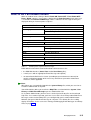
PAM Tree nodes . . . . . . . . . . . . . . . . . . . . . . . . . . . . . . . . . . . . . . . . . . . . . . . . . . . . . . . . . . . .
KVM port configuration . . . . . . . . . . . . . . . . . . . . . . . . . . . . . . . . . . . . . . . . . . . . . . . . . . . . . . .
KVM port configuration . . . . . . . . . . . . . . . . . . . . . . . . . . . . . . . . . . . . . . . . . . . . . . . . . . . . . . .
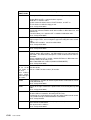
Domain states / power–on steps . . . . . . . . . . . . . . . . . . . . . . . . . . . . . . . . . . . . . . . . . . . . . . .
Domain states / power–off steps . . . . . . . . . . . . . . . . . . . . . . . . . . . . . . . . . . . . . . . . . . . . . . .
Domain states / force power–off steps . . . . . . . . . . . . . . . . . . . . . . . . . . . . . . . . . . . . . . . . . .
Domain states / reset steps . . . . . . . . . . . . . . . . . . . . . . . . . . . . . . . . . . . . . . . . . . . . . . . . . . .
Domain states / dump steps . . . . . . . . . . . . . . . . . . . . . . . . . . . . . . . . . . . . . . . . . . . . . . . . . .
Domain functional status indicators . . . . . . . . . . . . . . . . . . . . . . . . . . . . . . . . . . . . . . . . . . . .
Domain hardware details icons . . . . . . . . . . . . . . . . . . . . . . . . . . . . . . . . . . . . . . . . . . . . . . . .
Domain power sequence error messages . . . . . . . . . . . . . . . . . . . . . . . . . . . . . . . . . . . . . . .
CSS hardware functional status icons . . . . . . . . . . . . . . . . . . . . . . . . . . . . . . . . . . . . . . . . . .
Hardware presence status indicators . . . . . . . . . . . . . . . . . . . . . . . . . . . . . . . . . . . . . . . . . . .
Hardware functional status indicators . . . . . . . . . . . . . . . . . . . . . . . . . . . . . . . . . . . . . . . . . .
Fault status indicators . . . . . . . . . . . . . . . . . . . . . . . . . . . . . . . . . . . . . . . . . . . . . . . . . . . . . . . .
Power tab status indicators . . . . . . . . . . . . . . . . . . . . . . . . . . . . . . . . . . . . . . . . . . . . . . . . . . .
Temperature tab status indicators . . . . . . . . . . . . . . . . . . . . . . . . . . . . . . . . . . . . . . . . . . . . . .
Hardware exclusion guidelines . . . . . . . . . . . . . . . . . . . . . . . . . . . . . . . . . . . . . . . . . . . . . . . .
Event message and history file severity levels . . . . . . . . . . . . . . . . . . . . . . . . . . . . . . . . . . .
Specimen message help file . . . . . . . . . . . . . . . . . . . . . . . . . . . . . . . . . . . . . . . . . . . . . . . . . .
CSS functional status / domain state . . . . . . . . . . . . . . . . . . . . . . . . . . . . . . . . . . . . . . . . . . .
System disk configuration . . . . . . . . . . . . . . . . . . . . . . . . . . . . . . . . . . . . . . . . . . . . . . . . . . . .
HyperTerminal parameters . . . . . . . . . . . . . . . . . . . . . . . . . . . . . . . . . . . . . . . . . . . . . . . . . . . .
Storeway FDA 1300/2300 system disk configuration . . . . . . . . . . . . . . . . . . . . . . . . . . . . .
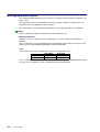
KVM ports . . . . . . . . . . . . . . . . . . . . . . . . . . . . . . . . . . . . . . . . . . . . . . . . . . . . . . . . . . . . . . . . . .
Boot Option Maintenance Menu . . . . . . . . . . . . . . . . . . . . . . . . . . . . . . . . . . . . . . . . . . . . . . .
KVM ports . . . . . . . . . . . . . . . . . . . . . . . . . . . . . . . . . . . . . . . . . . . . . . . . . . . . . . . . . . . . . . . . . .
Wildcard character expansion . . . . . . . . . . . . . . . . . . . . . . . . . . . . . . . . . . . . . . . . . . . . . . . . .
Output redirection syntax . . . . . . . . . . . . . . . . . . . . . . . . . . . . . . . . . . . . . . . . . . . . . . . . . . . . .
List of EFI Shell Commands . . . . . . . . . . . . . . . . . . . . . . . . . . . . . . . . . . . . . . . . . . . . . . . . . .
User access to PAM features . . . . . . . . . . . . . . . . . . . . . . . . . . . . . . . . . . . . . . . . . . . . . . . . .
Event channels . . . . . . . . . . . . . . . . . . . . . . . . . . . . . . . . . . . . . . . . . . . . . . . . . . . . . . . . . . . . . .
History automatic achiving policies . . . . . . . . . . . . . . . . . . . . . . . . . . . . . . . . . . . . . . . . . . . . .
Event channel selection guidelines . . . . . . . . . . . . . . . . . . . . . . . . . . . . . . . . . . . . . . . . . . . .
Standard event message filtering criteria . . . . . . . . . . . . . . . . . . . . . . . . . . . . . . . . . . . . . . .
Advanced event message filtering criteria . . . . . . . . . . . . . . . . . . . . . . . . . . . . . . . . . . . . . . .
NovaScale 5080/5160 Server specifications . . . . . . . . . . . . . . . . . . . . . . . . . . . . . . . . . . . .
BIOS POST code organization . . . . . . . . . . . . . . . . . . . . . . . . . . . . . . . . . . . . . . . . . . . . . . . .
BIOS error message organization . . . . . . . . . . . . . . . . . . . . . . . . . . . . . . . . . . . . . . . . . . . . .
SAL–A POST codes (before release B600) . . . . . . . . . . . . . . . . . . . . . . . . . . . . . . . . . . . . .
SAL–A POST codes (for releases B600 and later) . . . . . . . . . . . . . . . . . . . . . . . . . . . . . . .
SAL–A hang POST codes (before release B600) . . . . . . . . . . . . . . . . . . . . . . . . . . . . . . . .
SAL–B POST codes . . . . . . . . . . . . . . . . . . . . . . . . . . . . . . . . . . . . . . . . . . . . . . . . . . . . . . . . .
SAL–B hang POST codes . . . . . . . . . . . . . . . . . . . . . . . . . . . . . . . . . . . . . . . . . . . . . . . . . . . .
SAL–F POST codes . . . . . . . . . . . . . . . . . . . . . . . . . . . . . . . . . . . . . . . . . . . . . . . . . . . . . . . . .
SAL–F Hang POST Codes . . . . . . . . . . . . . . . . . . . . . . . . . . . . . . . . . . . . . . . . . . . . . . . . . . .
2-4
2-6
2-10
3-3
3-4
3-5
3-6
3-7
3-8
3-10
3-11
4-3
4-5
4-6
4-10
4-12
4-14
4-19
4-20
4-21
4-26
5-3
5-4
5-6
5-8
5-10
5-11
5-12
5-13
5-15
5-19
5-27
5-34
5-36
5-43
5-48
A-2
C-1
C-2
C-3
C-6
C-7
C-9
C-10
C-11
C-12
Preface
ix
Table 47.
Table 48.
Table 49.
Table 50.
Table 51.
Table 52.
Table 53.
Table 54.
Table 55.
Table 56.
Table 57.
Table 58.
Table 59.
Table 60.
Table 61.
Table 62.
x
IA–32 POST Codes . . . . . . . . . . . . . . . . . . . . . . . . . . . . . . . . . . . . . . . . . . . . . . . . . . . . . . . . . .
DIM Code checkpoints . . . . . . . . . . . . . . . . . . . . . . . . . . . . . . . . . . . . . . . . . . . . . . . . . . . . . . .
PCI diagnostic POST code format . . . . . . . . . . . . . . . . . . . . . . . . . . . . . . . . . . . . . . . . . . . . .
PCI diagnostic POST codes . . . . . . . . . . . . . . . . . . . . . . . . . . . . . . . . . . . . . . . . . . . . . . . . . .
EFI POST Codes . . . . . . . . . . . . . . . . . . . . . . . . . . . . . . . . . . . . . . . . . . . . . . . . . . . . . . . . . . . .
ACPI POST Codes . . . . . . . . . . . . . . . . . . . . . . . . . . . . . . . . . . . . . . . . . . . . . . . . . . . . . . . . . .
Recovery Port 80 POST codes (before release B600) . . . . . . . . . . . . . . . . . . . . . . . . . . . .
Recovery Port 80 POST codes (for releases B600 and later) . . . . . . . . . . . . . . . . . . . . . .
ACPI POST codes . . . . . . . . . . . . . . . . . . . . . . . . . . . . . . . . . . . . . . . . . . . . . . . . . . . . . . . . . . .
Boot error messages . . . . . . . . . . . . . . . . . . . . . . . . . . . . . . . . . . . . . . . . . . . . . . . . . . . . . . . . .
Storage error messages . . . . . . . . . . . . . . . . . . . . . . . . . . . . . . . . . . . . . . . . . . . . . . . . . . . . . .
System configuration error messages . . . . . . . . . . . . . . . . . . . . . . . . . . . . . . . . . . . . . . . . . .
CMOS error messages . . . . . . . . . . . . . . . . . . . . . . . . . . . . . . . . . . . . . . . . . . . . . . . . . . . . . . .
Miscellaneous error messages . . . . . . . . . . . . . . . . . . . . . . . . . . . . . . . . . . . . . . . . . . . . . . . .
PAM message list . . . . . . . . . . . . . . . . . . . . . . . . . . . . . . . . . . . . . . . . . . . . . . . . . . . . . . . . . . .
String length rules . . . . . . . . . . . . . . . . . . . . . . . . . . . . . . . . . . . . . . . . . . . . . . . . . . . . . . . . . . .
User’s Guide
C-22
C-23
C-24
C-24
C-25
C-25
C-26
C-27
C-28
C-29
C-29
C-30
C-31
C-31
C-41
C-42
Overview
Intended Readers
This guide is intended for use by the Administrators and Operators of Bull NovaScale 5000
Series servers.
Chapter 1. Introducing the Server
describes server hardware components and user environment.
Chapter 2. Getting Started
explains how to connect to and use the server.
Chapter 3. Managing Domains
describes how to perform straightforward server domain management tasks.
Chapter 4. Monitoring the Server
explains how to supervise server operation.
Chapter 5. Tips and Features for Administrators
explains how, as Customer Administrator, you can configure the server to suit your
environment.
Appendix A. Specifications and Features
Appendix B. NovaScale 5080/5160 Server Cabling
Appendix C. Error Messages and Recovery Information
Highlighting
The following highlighting conventions are used in this guide:
Bold
Identifies predefined commands, subroutines, keywords, files,
structures, buttons, labels, and icons.
Italics
Identifies referenced publications, chapters, sections, figures,
and tables.
<
>
Identifies parameters to be supplied by the user.
Preface
xi
Related Publications
Site Preparation Guide, 86 A1 87EF
explains how to prepare a Data Processing Center for Bull NovaScale Servers, in
compliance with the standards in force. This guide is intended for use by all personnel
and trade representatives involved in the site preparation process.
Installation Guide, 86 A1 88EF
explains how to set up and start Bull NovaScale 5000 Series servers for the first time.
This guide is intended for use by qualified support personnel.
Maintenance and Service Guide, 86 A7 90EF
explains how to maintain, service, and upgrade Bull NovaScale 5000 Series servers. This
guide is intended for use by qualified support personnel.
Troubleshooting Guide, 86 A7 91EF
explains how to diagnose and solve any problems occurring during Bull NovaScale
Server operation. This guide is intended for use by qualified support personnel.
Documentation Overview, 86 A2 XXXX
describes the hardware, software and online documentation available for Bull NovaScale
Servers, related Operating Systems, and licensed programs.
Note:
According to Server configuration and version, certain features and functions described in
this guide may not be accessible. Please contact your Bull Sales Representative for sales
information.
xii
User’s Guide
Regulatory Specifications and Disclaimers
Declaration of the Manufacturer or Importer
We hereby certify that this product is in compliance with European Union EMC Directive
89/336/EEC, using standards EN55022 (Class A) and EN55024 and Low Voltage Directive
73/23/EEC, using standard EN60950. The product has been marked with the CE Mark to
illustrate its compliance.
Safety Compliance Statement
• UL 60950 (USA)
• IEC 60950 (International)
• CSA 60950 (Canada)
European Community (EC) Council Directives
This product is in conformity with the protection requirements of the following EC Council
Directives:
Electromagnetic Compatibility
• 89/336/EEC
Low Voltage
• 73/23/EEC
EC Conformity
• 93/68/EEC
Telecommunications Terminal Equipment
• 199/5/EC
Neither the provider nor the manufacturer can accept responsibility for any failure to satisfy
the protection requirements resulting from a non-recommended modification of the product.
Compliance with these directives requires:
• an EC declaration of conformity from the manufacturer
• an EC label on the product
• technical documentation
Preface
xiii
Federal Communications Commission (FCC) Statement
Note:
This equipment has been tested and found to comply with the limits for a Class A digital
device, pursuant to Part 15 of the FCC Rules. These limits are designed to provide
reasonable protection against harmful interference when the equipment is operated in a
commercial environment. This equipment generates, uses, and can radiate radio frequency
energy and, if not installed and used in accordance with the instruction manual, may cause
harmful interference to radio communications. Operation of this equipment in a residential
area is likely to cause harmful interference in which case the user will be required to correct
the interference at his own expense.
Properly shielded and grounded cables and connectors must be used in order to meet FCC
emission limits. Neither the provider nor the manufacturer are responsible for any radio or
television interference caused by using other than recommended cables and connectors or
by unauthorized changes or modifications to this equipment. Unauthorized changes or
modifications could void the user’s authority to operate the equipment.
Any changes or modifications not expressly approved by the grantee of this device could
void the user’s authority to operate the equipment. The customer is responsible for ensuring
compliance of the modified product.
FCC Declaration of Conformity
This device complies with Part 15 of the FCC Rules. Operation is subject to the following
two conditions: (1) this device may not cause harmful interference, and (2) this device must
accept any interference received, including interference that may cause undesired
operation.
Canadian Compliance Statement (Industry Canada)
This Class A digital apparatus meets all requirements of the Canadian Interference Causing
Equipment Regulations.
Cet appareil numérique de la classe A est conforme à la norme NMB–003 du Canada.
This product is in conformity with the protection requirements of the following standards:
Electromagnetic Compatibility
• ICES–003
• NMB–003
Laser Compliance Notice
This product that uses laser technology complies with Class 1 laser requirements.
A CLASS 1 LASER PRODUCT label is located on the laser device.
Class 1 Laser Product
Luokan 1 Laserlaite
Klasse 1 Laser Apparat
Laser Klasse 1
xiv
User’s Guide
Definition of Safety Notices
DANGER
A Danger notice indicates the presence of a hazard that has the potential of causing
death or serious personal injury.
CAUTION:
A Caution notice indicates the presence of a hazard that has the potential of causing
moderate or minor personal injury.
Warning:
A Warning notice indicates an action that could cause damage to a program, device,
system, or data.
Electrical Safety
The following safety instructions shall be observed when connecting or disconnecting
devices to the system.
DANGER
The Customer is responsible for ensuring that the AC electricity supply is compliant
with national and local recommendations, regulations, standards and codes of
practice.
An incorrectly wired and grounded electrical outlet may place hazardous voltage on
metal parts of the system or the devices that attach to the system and result in an
electrical shock.
It is mandatory to remove power cables from electrical outlets before relocating the
system.
CAUTION:
This unit has more than one power supply cable. Follow procedures for removal of
power from the system when directed.
Preface
xv
Laser Safety Information
The optical drive in this system unit is a classified as a Class 1 level Laser product. The
optical drive has a label that identifies its classification.
The optical drive in this system unit is certified in the U.S. to conform to the requirements of
the Department of Health and Human Services 21 Code of Federal Regulations (DHHS 21
CFR) Subchapter J for Class 1 laser products. Elsewhere, the drive is certified to conform to
the requirements of the International Electrotechnical Commission (IEC) 60825–1: 2001 and
CENELEC EN 60825–1: 1994 for Class 1 laser products.
CAUTION:
Invisible laser radiation when open. Do not stare into beam or view directly with
optical instruments.
Class 1 Laser products are not considered to be hazardous. The optical drive contains
internally a Class 3B gallium–arsenide laser that is nominally 30 milliwatts at 830
nanometers. The design incorporates a combination of enclosures, electronics, and
redundant interlocks such that there is no exposure to laser radiation above a Class 1 level
during normal operation, user maintenance, or servicing conditions.
Data Integrity and Verification
Warning:
Bull NovaScale Servers are designed to reduce the risk of undetected data corruption
or loss. However, if unplanned outages or system failures occur, users are strongly
advised to check the accuracy of the operations performed and the data saved or
transmitted by the system at the time of outage or failure.
xvi
User’s Guide
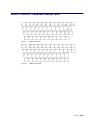
AZERTY/QWERTY Keyboard Lookup Table
Figure 1.
AZERTY keyboard
Figure 2.
QWERTY keyboard
Preface
xvii
xviii
User’s Guide
Administrator’s Memorandum
Domains
• Power ON the a Domain, on page 3-3
• Power OFF the a Domain, on page 3-4
• Perform a Domain Force Power OFF, on page 3-5
• Perform a Manual Domain Reset, on page 3-6
• Perform a Domain Memory Dump, on page 3-7
• View Domain Functional Status, on page 3-8
• View Power Logs, on page 3-8
• View BIOS Info, on page 3-8
• View Domain Hardware Resources, on page 3-9
• Solve Incidents, on page 3-11
Monitoring
• Refresh the PAM Display, on page 4-2
• View PAM Web Site User Information, on page 4-7
• View PAM Version Information, on page 4-7
• View Server Hardware Status, on page 4-8
• Display Detailed Hardware Information, on page 4-9
• Use the Hardware Search Engine, on page 4-16
• Exclude / Include Hardware Elements, on page 4-17
• Display Faults List, on page 4-22
• Solve Incidents, on page 4-25
Histories
• View, Manage PAM Event Messages, History Files, on page 4-20
• Understand Event Message and History Severity Levels, on page 4-20
• Consult Event Messages, Hardware Faults List, History Files, on page 4-21
• View, Archive, Delete History / Archive files, on page 4-23
• Sort and Locate messages, on page 4-24
Status
• Check System Functional Status, on page 4-3
• Check CSS Availability, on page 4-3
• View, Acknowledge WEB Event Messages, on page 4-22
• Sort, Locate WEB Event Messages, on page 4-24
Preface
xix
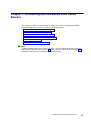
Configuration
• Set up Server Users, on page 5-2
• Configure SR–0812 / SR–1422 Data Disks, on page 5-3
• Configure Storeway FDA 1300 / 2300 Data Disks, on page 5-6
• Use the EFI Boot Manager, on page 5-8
• Use the EFI Shell, on page 5-11
• Set Up and Configure the EFI Network, on page 5-16
• Set up PAP Unit Users, on page 5-18
• Modify Customer Information, on page 5-18
• Configure PAM Autocall Parameters, on page 5-21
• Customize PAM Settings, on page 5-22
• Deploy a New PAM Release, on page 5-23
• Activate a PAM Version, on page 5-24
• Customize the PAM Event Messaging System, on page 5-26
• Set up Event Subscriptions, on page 5-27
• Event Subscription Flowcharts, on page 5-27
• Create, Edit, Delete an E–mail Server, on page 5-29
• Create, Edit, Delete an E–mail Account, on page 5-31
• Create, Edit, Delete a User History , on page 5-33
• Enable / Disable Event Channels, on page 5-36
• Create, Edit, Delete an Event Subscription, on page 5-37
• Understand Event Message Filtering Criteria, on page 5-39
• Preselect an Event Filter, on page 5-49
• Create, Edit, Delet an Event Filter, on page 5-50
xx
User’s Guide
Operator’s Memorandum
Domains
• Power ON a Domain, on page 3-3
• Power OFF a Domain, on page 3-4
• Perform a Domain Force Power OFF, on page 3-5
• Perform a Manual Domain Reset, on page 3-6
• Perform a Domain Memory Dump, on page 3-7
• View Domain Functional Status, on page 3-8
• View Power Logs, on page 3-8
• View BIOS Info, on page 3-8
• View Domain Hardware Resources, on page 3-9
• Solve Incidents, on page 3-11
Histories
• View, Manage PAM Event Messages, History Files, on page 4-20
• Understand Event Message and History Severity Levels, on page 4-20
• Consult Event Messages, Hardware Faults List, History Files, on page 4-21
• View, Archive, Delete History / Archive files, on page 4-23
• Sort and Locate messages, on page 4-24
Status
• Check System Functional Status, on page 4-3
• Check CSS Availability, on page 4-3
• View, Acknowledge WEB Event Messages, on page 4-22
• Sort, Locate WEB event messages, on page 4-24
Preface
xxi
xxii
User’s Guide
Chapter 1. Introducing Bull NovaScale 5000 Series
Servers
This chapter describes the main hardware components and user environment for Bull
NovaScale 5000 Series Servers. It includes the following topics:
• Bull NovaScale Server Overview, on page 1-2
• Getting to Know the Server, on page 1-4
• Accessing Server Components, on page 1-13
• Bull NovaScale Server Resources, on page 1-17
• EFI Utilities, on page 1-17
• PAM Software Package, on page 1-17
Note:
Customer Administrators and Customer Operators are respectively advised to consult the
Administrator’s Memorandum, on page xix or the Operator’s Memorandum, on page xxi for
a detailed summary of the everyday tasks they will perform.
Introducing NovaScale 5080/5160 Servers
1-1
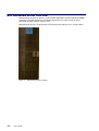
Bull NovaScale Server Overview
Bull NovaScale Servers for business and scientific applications are based upon the FAME
architecture (Flexible Architecture for Multiple Environments) and leverage the latest
generation of Intel Itanium 2 processors.
Bull NovaScale Servers are delivered rack–mounted and ready–to–use in a high cabinet.
Figure 3.
1-2
User’s Guide
Bull NovaScale Server cabinet
The main features of Bull NovaScale Servers are:
Intel Itanium Processor Family architecture:
– Modularity, predictable performance and growth.
Simultaneous support of multiple environments:
– Microsoft Windows Server,
– Linux.
High performance computing capabilites:
– Business Intelligence:
. Datawarehousing.
. Datamining.
– Large enterprise applications:
. ERP.
. CRM.
. SCM, ...
– Large database applications for Internet transactions.
– Large business sector applications:
. Online billing.
. Online reservations.
. Online banking.
High availability:
– Component redundancy.
– Capacity to isolate or replace a faulty components without service disruption.
– Global and unified system visibility.
– Round–the–clock operation.
Scalability:
– Dynamic partitioning.
– Capacity to dynamically adapt resources to load requirement.
Built–in Platform Administration and Maintenance (PAM) software suite:
– Proactive administration.
– Optimization of resources.
– Automatic generation of corrective actions and calls to support centers.
– Dynamic configuration.
Bull System Management (BSM) software suite:
– Windows, Linux, and Platform management.
– Monitoring, Information, Control, and Event Handling.
– Client / Server / Agent architecture.
– WEB standard OpenSource solutions.
Introducing NovaScale 5080/5160 Servers
1-3
Getting to Know Bull NovaScale Servers
Note:
Abbreviations and acronyms are documented in the Glossary.
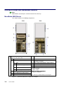
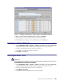
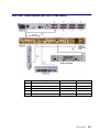
NovaScale 5080 Server
The cabinet contains the following components:
Front
1
CSS module with midplane, redundant power
supply and AC power cable
11
Console drawer with monitor, keyboard and mouse
2
DPS units
12
KVM switch
3
1 or 2 IOB (s) with:
13
1 or two SCSI or FC disk rack(s) with RAID
controller(s) and disks
4
IOR
14
PAP unit with CD–ROM drive, FDD and disk(s)
5
LS240 disk drive (optional)
15
PDU with AC power cable
16
Ethernet hub with power bar (FC disk rack)
6
DVD / CD–ROM drive
7
PCI hot plug board (11 slots)
8
PMB
9
1 or 2 QBB subsets with fan boxes
10
SPS fan boxes
Figure 4.
1-4
Rear
User’s Guide
Dual IOB configuration:
– IOB #0 = Master
– IOB #1 = Slave
NovaScale 5080 configuration:
– QBB #0 and QBB #3
See Glossary for abbreviations and acronyms.
NovaScale 5080 Server components (example)
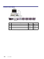
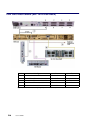
NovaScale 5160 Server
The cabinet contains the following components:
Front
1
CSS module with midplane, redundant power
supply and AC power cable
Rear
11
Console drawer with monitor, keyboard and mouse
2
DPS units
12
KVM switch
3
1 or 2 IOB (s) with:
13
1 or two SCSI or FC disk rack(s) with RAID
controller(s) and disks
4
IOR
14
PAP unit with CD–ROM drive, FDD and disk(s)
5
LS240 disk drive (optional)
15
PDU with AC power cable
16
Ethernet hub with power bar (FC disk rack)
6
DVD / CD–ROM drive
7
PCI hot plug board (11 slots)
8
PMB
9
1 up to 4 QBB subsets with fan boxes
10
SPS fan boxes
Figure 5.
Dual IOB configuration:
– IOB #0 = Master
– IOB #1 = Slave
NovaScale 5160 configuration:
– QBB #0, QBB #1, QBB #2, and QBB #3
See Glossary for abbreviations and acronyms.
NovaScale 5160 Server components (example)
Introducing NovaScale 5080/5160 Servers
1-5
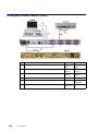
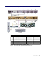
Server Components
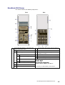
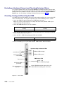
Central Subsystem (CSS) Module
The CSS Module houses core hardware components. The CSS Module is located at the
bottom of the cabinet.
1 MPI (MidPlane)
This active board is used to interconnect the QBBs, IOBs and the PMB.
2 SPS fan boxes
Each MPI is equipped with two redundant fan boxes for cooling.
1, 2, 3 or 4 QBB (Quad Brick Board) subsets:
Each QBB subset houses:
• 1 mother board
• 2 memory boards
• 4 processors
• 16 DIMMs
1, 2, 3 or 4 QBB fan boxes:
Each QBB subset is equipped with a fan box for cooling.
1 or 2 IOBs (Input / Output Box):
Each IOB box houses:
• 1 IOB (Input / Output Board)
• 1 PHPB (PCI Hot Plug Board)
• 11 hot–plug PCI–X (100–133 MHz) slots with optional:
– 1 SCSI HBA
– 1 PCI SCSI card
– 1 PCI FC card
– 1 PCI Giga Ethernet card
– 8 free slots
• 1 IOR (Input / Output Riser):
– 2 A–type USB ports
• 1 RJ45 10/100 Mbps Ethernet port
– 2 DB9–M RS232 serial ports
– 1 HD15–F VGA port
• 1 DVD/CD–ROM drive
• 1 LS240 drive (optional)
Each IOB is cooled by the corresponding QBB fan box.
1 PMB (Platform Management Board):
This active board links the server to the Platform Administration Processor (PAP) Unit
(via an Ethernet link).
Figure 6.
1-6
User’s Guide
CSS module features
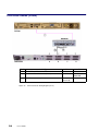
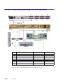
Console Drawer
The Console Drawer contains the keyboard, monitor and mouse used for local access to the
server and to the Platform Administration Processor (PAP) Unit. The Console drawer is
located in the center of the cabinet for easy access and comfortable use.
• 1 pull–out table top
• 1 monitor
• 1 QWERTY keyboard and mouse kit
• 1 power cable
Figure 7.
Console drawer features
Note:
The server is designed for remote access. See Configuring Remote Access to the Server,
on page 2-10.
Keyboard / Video / Mouse (KVM) Switch
The KVM Switch allows the use of a single keyboard, monitor and mouse for the local
server and the local Platform Administration and Maintenance console. The KVM Switch is
located in the center of the cabinet, above the CSS Module.
Avocent 400 KVM Switch
• 8 ports
• 1 power cable
Avocent 1000R KVM Switch
• 16 ports
• 1 power cable
Figure 8.
KVM switch features
Introducing NovaScale 5080/5160 Servers
1-7
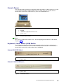
SR–0812 Disk Rack
The SR–0812 SCSI Disk Rack is delivered with four system disks (two RAID#1 and two
spare disks) and offers four empty slots for Customer data disks. The Disk Rack is located
in the center of the cabinet, above the PAP Unit.
1 OS disks
2 Spare disks
3 Optional data disks
• 8 slots
• 1 RAID controller card
• 4 disks (configuration: 2 in RAID#1 + 2 in pool spare)
• 2 power cables (redundant power supply)
Figure 9.
SR–0812 SCSI disk rack features
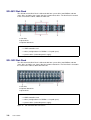
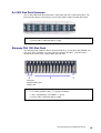
SR–1422 Disk Rack
The SR–1422 SCSI Disk Rack is delivered with four system disks (two RAID#1 and two
spare disks) and offers ten empty slots for Customer data disks. The Disk Rack is located in
the center of the cabinet, above the PAP Unit.
1 OS disks
2 Optional data disks
3 Spare disks
• 14 slots
• 2 RAID controller cards
• 4 disks (configuration: 2 in RAID#1 + 2 in pool spare)
• 2 power cables (redundant power supply)
Figure 10.
1-8
User’s Guide
SR–1422 SCSI disk rack features
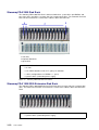
SJ–0812 Disk Rack Extension
The SJ–0812 Extension Disk Rack offers eight empty slots for Customer data disks. The
Extension Disk Rack is located in the center of the cabinet, above the Main Disk Rack.
• 8 slots
• 2 power cables (redundant power supply)
Figure 11.
SJ–0812 SCSI extension disk rack features
Storeway FDA 1300 Disk Rack
The Storeway FDA 1300 Disk Rack is delivered with three system disks (two RAID#1 and
one spare disks) and offers 12 empty slots for Customer data disks. The Disk Rack is
located in the center of the cabinet, above the PAP Unit.
1 OS disks
2 Optional data disks
3 Spare disk
• 15 slots
• 2 FC RAID controller cards, 1 FC port per controller
• 3 disks (configuration: 2 in RAID#1 + 1 spare)
• 2 power cables (redundant power supply)
Figure 12.
Storeway FDA 1300 disk rack features
Introducing NovaScale 5080/5160 Servers
1-9
Storeway FDA 2300 Disk Rack
The Storeway FDA 2300 Disk Rack is delivered with three system disks (two RAID#1 and
one spare disks) and offers 12 empty slots for Customer data disks. The Controller Unit and
Disk Unit are located in the center of the cabinet, above the PAP Unit.
1 OS disks
2 Optional data disks
3 Spare disk
• 1 controller unit & 1 disk unit
• 15 slots
• 2 FC RAID controller cards, 2 FC ports per controller
• 3 disks (configuration: 2 in RAID#1 + 1 spare)
• 2 power cables (redundant power supply)
Figure 13.
Storeway FDA 2300 disk rack features
Storeway FDA 1300/2300 Extension Disk Rack
The Storeway FDA 1300/2300 Extension Disk Rack offers15 empty slots for Customer data
disks. The Extension Disk Rack is located in the center of the cabinet, above the Main Disk
Rack.
• 15 slots
• 2 power cables (redundant power supply)
Figure 14.
1-10
User’s Guide
Storeway FDA 1300/2300 extension disk rack features
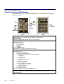
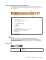
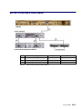
Platform Administration Processor (PAP) Unit
The PAP unit is linked to the server via the Platform Management Board (PMB). It hosts
platform administration software. The PAP unit is located in the center of the cabinet, above
the Console Drawer.
• 1 PIII / 1 GHz PC
– 512 Mo RAM
– 2 x 36 Gb disks (soft mirrored) (3)
– 1 free disk slot (4)
– 1 CD/DVD–ROM drive (1)
– 1 FDD(2)
– 2 serial ports
– 2 PCI slots
– 2 Ethernet ports (1 free)
• Microsoft Windows 2000 Server operating system
• Microsoft Internet Explorer 6 software
• PAM software
• 1 power cable
Figure 15.
PAP unit features
Warning:
The PAP unit has been specially configured for Bull NovaScale Servers
administration and maintenance. NEVER use the PAP unit for other purposes and
NEVER change PAP unit configuration unless instructed to do so by an authorized
Customer Service Engineer.
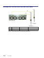
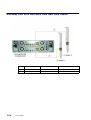
Ethernet Hub
Ethernet Hub
Figure 16.
–
8 ports
–
1 power cable
–
1 power bar
Ethernet hub features
Introducing NovaScale 5080/5160 Servers
1-11
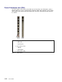
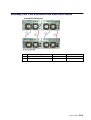
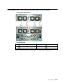
Power Distribution Unit (PDU)
The PDU supplies mains power to the PAP unit, the Disk Rack, the KVM Switch, and the
Monitor. When the server is equipped with a Storeway FDA 1300 / 2300 disk rack, the PDU
also supplies mains power to the Hub Power Bar. The PDU is located in the top left part of
the cabinet.
Front
Rear
• 6 (8A) sockets (front):
– PAP Unit
– Disk Rack(s)
• 2 (1A) sockets (rear):
– Monitor
– KVM Switch
• 1 (20A) power cable
Figure 17.
1-12
User’s Guide
PDU features
Accessing Server Components
During normal operation, cabinet components can be accessed from the front. Customer
Service Engineers may also remove the rear and side covers for certain maintenance
operations.
Important:
Optimum cooling and airflow is ensured when the cabinet door is closed.
Opening the Front Door
Tools Required:
• Cabinet key
Figure 18.
Opening the front door
1. Unlock the front door with the key.
2. Pull out the locking mechanism and turn to open.
3. Open the door as required (90° / 180°).
Closing the Front Door
1. Close the door.
2. Turn the locking mechanism to close and push back into place.
3. Lock the front door with the key.
Introducing NovaScale 5080/5160 Servers
1-13
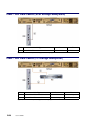
Setting up the Console Drawer
Figure 19.
Lowering the console drawer flap
1. Pull out the console drawer and lower the magnetic front flap.
Figure 20.
Extending the mouse tray
2. Pull on the tab to extend the mouse tray.
Figure 21.
Positioning the monitor
3. Manually position the monitor and check that the vacation switch on the right–hand side
of the monitor is ON.
1-14
User’s Guide
Figure 22.
Console ready for use
4. Install the mouse on the extendable tray, ready for use.
Closing the Console Drawer
1. Replace the mouse on the pad inside the drawer and push on the tab to replace the
mouse tray in its housing.
2. Raise the magnetic front flap.
3. Manually lower the monitor.
4. Press firmly on the tabs on each side of the drawer and push the drawer back into the
cabinet.
(1) Tab (1 on each side of the drawer)
Figure 23.
Closing the console drawer
Introducing NovaScale 5080/5160 Servers
1-15
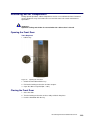
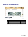
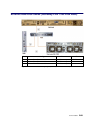
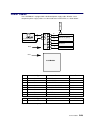
Accessing the PAP Unit CD–Rom and Diskette Drives
Tools Required:
• PAP unit key
The PAP unit CD–Rom and diskette drives are located behind the front bezel. To access the
CD–Rom and/or diskette drives, unlock the front bezel with the PAP unit key and remove.
Figure 24.
1-16
User’s Guide
PAP Unit CD–Rom and Diskette Drives
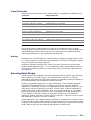
Bull NovaScale Server Resources
Note:
According to Server configuration and version, certain features and functions described in
this guide may not be accessible. Please contact your Bull Sales Representative for sales
information.
System Resource CD
The Bull NovaScale Server System Resource CD contains all the firmware and
documentation referred to in this guide.
EFI Utilities
The Bull NovaScale Server EFI utilities provide a complete set of configuration, operation,
and maintenance tools:
• EFI driver,
• EFI Shell,
• EFI system utility,
• EFI system diagnostic,
• Operating System loader.
For further details, see Chapter 5. Tips and Features for Administrators.
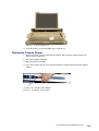
PAM Software Package
The Bull NovaScale Server is equipped with an integrated Platform Administration and
Maintenance software package, otherwise known as the PAM software package.
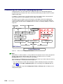
One part of PAM software is an embedded application (MAESTRO) running on the Platform
Management Board(s) (PMB) and the other is an external application (PAM Kernel / Web
User Interface) running on the Platform Administration Processor (PAP) unit under Microsoft
Windows 2000 Server.
CSS Module
Access to
Hardware Elements
PMB
(MAESTRO)
Internal Ethernet Link
PAP Unit
(PAM Kernel / Web User Interface)
Figure 25.
PAM software deployment
Introducing NovaScale 5080/5160 Servers
1-17
The PAM Web–based administration and maintenance tools give you immediate insight into
system status and configuration. You will use PAM software to operate, monitor, and
configure your Bull NovaScale Server.
As soon as your system is connected to the power supply, the PAP unit running Microsoft
Windows 2000 Server and PAM software also powers up.
For further information about connecting to PAM, see Connecting to the PAM Web Site, on
page 2-2.
PAP Unit Mirroring and Failover Policy
Most configuration, administration, and maintenance activities are carried out from the PAP
unit. To ensure a high level of data integrity and availability, the PAP unit is equipped with
two extractable mirrored disks. Mirroring writes and updates data across both disks,
creating a single logical volume with completely redundant information on each disk. If one
disk fails, it can be replaced without losing data.
1-18
User’s Guide
Chapter 2. Getting Started
This chapter describes how to connect to and use the Bull NovaScale 5000 Series server. It
includes the following topics:
• Connecting to the PAM Web Site, on page 2-2
• PAM User Interface, on page 2-4
• Toggling the Local / Integrated Console Display, on page 2-6
• Powering Up / Down the Server Domain, on page 2-8
• Connecting to the Server via the Local / Integrated Console, on page 2-10
• Connecting to the Server via the Enterprise LAN, on page 2-11
• Connecting to the Server via the Web, on page 2-13
Note:
Customer Administrators and Customer Operators are respectively advised to consult the
Administrator’s Memorandum, on page xix or the Operator’s Memorandum, on page xxi for
a detailed summary of the everyday tasks they will perform.
Getting Started
2-1
Connecting to the PAM Web Site
The server is equipped with an integrated Platform Administration and Maintenance
software package, otherwise known as PAM software.
One part of PAM software is an embedded application (MAESTRO) running on the Platform
Management Board (PMB) and the other is an external application running on the Platform
Administration Processor (PAP) unit under Microsoft Windows 2000 Server.
The PAM user interface is divided into three areas in the browser window: a Status pane, a
PAM Tree pane, and a Control pane, allowing users to check system status at a glance.
Figure 26.
PAM Home Page
The PAM Web–based administration and maintenance tools give you immediate insight into
system status and configuration. You will use PAM software to operate, monitor, and
configure your Bull NovaScale Server.
Local Connection
From the integrated console, check that the KVM switch is set to the PAP unit port and click
the PAM icon to access the PAM Web site. See Toggling the Local / Integrated Console
Display, on page 0.
2-2
User’s Guide
Remote Connection
Important:
Before connecting to PAM from a remote computer, you are advised to disconnect
from your local Windows session on the PAP unit by clicking Start → Log Off.
You can connect to PAM from any remote computer running under Microsoft Windows using
Microsoft Internet Explorer 6:
1. From the remote computer, configure Microsoft Internet Explorer 6 to connect directly to
the PAM Web site:
a. From the Microsoft Internet Explorer 6 main menu bar, select Tools → Internet
Options → Home Page.
b. Type the PAM Web site URL defined during the PAP installation procedure in the
home page address field: http://<PAP unitname>/pam.
c. Save your changes and close Microsoft Internet Explorer 6.
2. Open Microsoft Internet Explorer 6 to connect directly to the PAM web site.
3. When requested, enter the appropriate user id and password. The PAM home page
appears.
Notes:
If Microsoft Internet Explorer 6 or later is not installed on the remote computer, it can be
downloaded from the Microsoft Web site. If the operating system on the client computer is
Microsoft Windows XP, also download Java VM from the Microsoft Web site.
Local and remote access rights to the PAP unit and to the PAM Web site must be
configured by the Customer Administrator. For further details, refer to the Microsoft
Windows documentation and to Setting up PAP Unit Users, on page 5-18.
Several users can access the PAM Web site simultaneously and several browser sessions
can also be opened from the same computer to obtain different views of system operation.
Important:
If configuration changes are made, they may not be visible to other users unless they
refresh the PAM Tree.
Getting Started
2-3
PAM User Interface
The PAM user interface is divided into three areas: a Status pane, a PAM Tree pane, and a
Control pane.
Status Pane
The Status pane provides quick access to the following synthetic information:
• Functional Status: if the system is operating correctly, the status icon is green,
• Event Messages: shows the number and maximum severity of pending event messages,
• CSS Availability Status: if the CSS Module is present, configured correctly, and the
PMB is ready to operate, the status bar is green.
Figure 27.
Status pane
Note:
The Status pane is automatically refreshed every few seconds.
PAM Tree Pane
The PAM Tree pane provides access to server administration and maintenance features:
Menu Nodes
Domain Manager
to power on / off and manage domains.
See Chapter 3. Managing Domains.
Hardware Monitor
to display the status of hardware components and assemblies.
See Chapter 4. Monitoring the Server.
History Manager
to view logs and manage archives.
See Chapter 4. Monitoring the Server.
Configuration Tasks
to customize server features.
See Chapter 5. Tips and Features for Administrators.
Table 1.
2-4
Function
User’s Guide
PAM Tree nodes
PAM Tree Toolbar
The PAM Tree toolbar, located at the top of the PAM Tree, is used to refresh, expand, or
collapse the tree display.
Toolbar Buttons
Meaning
Refresh /rebuild the PAM Tree to view changes.
Expand the complete tree.
Collapse the complete tree.
Expand selected node.
Collapse selected node
View the related Help topic.
Figure 28.
PAM Tree toolbar
Note:
The PAM Tree pane is refreshed at your request.
Control Pane
When an item is selected in the PAM Tree pane, details and related commands are
displayed in the Control pane.
Note:
The Control pane is automatically refreshed every minute.
Getting Started
2-5
Simultaneous Connection
Important:
Before connecting to PAM from a remote computer, you are advised to disconnect
from your local Windows session on the PAP unit by clicking Start → Log Off.
As Customer Administrator, you can view the list of PAM users currently logged onto the
PAM Web site by clicking Hardware Monitor → PAM Web Site.
The Web site version and a list of connected users and session details are displayed in the
Control pane.
Figure 29.
PAM Web site session details
Note:
icon indicates the current session.
The
Toggling the Local / Integrated Console Display
The KVM Switch allows the integrated keyboard, monitor and mouse to be used as the local
server and local PAP unit console. KVM ports are configured as shown in Table 2.
AV 400 KVM Port
Console Display
Port A
PAP Unit
Port B (PS2)
Microsoft Windows domain
Port C (USB)
Linux domain
AV 1000R KVM Port
Console Display
Port 1
PAP Unit
Port 3
Domain 0 (IOB #0)
Port 4
Domain 1 (IOB #1)
Table 2.
KVM port configuration
You can easily toggle from the server display to the PAP unit display:
1. From the keyboard, press the Control key twice to display the KVM Switch Comand
Menu.
2. Select the required port with the ↑↓ keys and press Enter.
3. The selected display appears on the Console monitor.
2-6
User’s Guide
Setting up Users
As Customer Administrator, you must set up user accounts and passwords to control access
to the PAP unit. See Setting up PAP Unit Users, on page 5-18.
Getting Started
2-7
Powering Up / Down the Server Domain
The Bull NovaScale 5000 Series server is designed to operate as a single SMP system and
is delivered with one pre–configured domain.
When server status has been checked – functional status icon and CSS availability status
bar green in the Status pane – the server domain can be powered up.
Powering Up the Domain
1. From the PAM Tree, click Domain Manager to open the Control pane. If the server
domain is in the stand–by mode, INACTIVE is displayed in the Domain Status panel
and the Power ON button is accessible.
2. Click Power ON to power up the server domain and associated hardware components.
Domain Status panel
Functional status icon &
CSS availability status indicator
GREEN
Figure 30.
Power ON step and state indicators
Domain Manager Control pane
Note:
For further details about the Power ON sequence, see Powering ON the Domain, on page
3-3.
3. Toggle the local / integrated console from the PAP unit display to the server display. See
Toggling the Local / Integrated Console Display, on page 2-6.
2-8
User’s Guide
Powering Down the Domain
1. Shut down the server domain from the Operating System.
2. Toggle the local / integrated console from the server display to the PAP unit display. See
Toggling the Local / Integrated Console Display, on page 2-6.
Note:
For further details about the Power OFF sequence, see Powering OFF the Domain, on
page 3-4.
Note:
If required, the server domain can also be powered OFF from the PAM Domain Manager. If
the Operating System is configured to accept a PAM Power OFF command, it will
automatically save data, close open applications, and shut down the server domain:
1. Toggle the local / integrated console from the server display to the PAP unit display. See
Toggling the Local / Integrated Console Display, on page 2-6.
2. From the PAM Tree, click Domain Manager to open the Control pane. If the server
domain is powered up, RUNNING is displayed in the Domain Status panel and the
Power OFF button is accessible.
3. Click Power OFF. The server domain and associated hardware components will be
powered down to the stand–by mode.
Getting Started
2-9
Connecting to the Server via the Local / Integrated Console
CAUTION:
Access to the local / integrated console should be restricted to Customer / Service
Administrators and Operators ONLY to avoid inadvertent damage to software and/or
hardware components.
The KVM Switch allows the integrated keyboard, monitor and mouse to be used as the local
server / PAP unit console.
To toggle from the local PAP unit display to the local server display:
1. Press the Control key twice to display the KVM Switch Comand Menu.
2. Select the required port with the ↑↓ keys and press Enter.
Console Display
AV 400 KVM Port
Port A
PAP Unit
Port B (PS2)
Microsoft Windows domain
Port C (USB)
Linux domain
AV 1000R KVM Port
Console Display
Port 1
PAP Unit
Port 3
Domain 0 (IOB #0)
Port 4
Domain 1 (IOB #1)
Table 3.
KVM port configuration
3. The selected display appears on the Console monitor.
2-10
User’s Guide
Connecting to the Server via the Enterprise LAN
Microsoft Windows
Preparing the Server for Remote Access via the Enterprise LAN
1. Toggle the integrated console to the corresponding Windows domain port. See Toggling
the Local / Integrated Console Display, on page 2-6.
2. From the Windows desktop, right click My Computer and select Properties → Remote.
3. Check the Allow remote connection box.
4. Share the <system root>\system32\clients\tsclient directory via the Explorer.
Connecting a Remote Computer to the Server via the Enterprise LAN
1. Check that the Client for Microsoft Networks has been installed on the computer.
2. Check that the computer is connected to the same LAN as the Bull NovaScale Server.
3. Check that the Client for Remote Desktop has been intalled on the computer. If the
Remote Desktop Connection menu does not exist:
a. Click Start → Run.
b. Type \\<servername>\tsclient\win32\setup.exe in the box, where <servername> is
the name given to the Bull NovaScale Server during the setup completion procedure.
See the Read Me First document delivered with the server.
4. Connect to the Bull NovaScale Server by running:
a. Microsoft Windows XP (and later):
All Programs → Accessories → Communication → Remote Desktop
Connection.
b. All other versions of Microsoft Windows:
Programs → Remote Desktop Connection → OK.
5. Type Administrator (default administrator user name) in the User name field.
6. Type the administrator password defined by the Customer during the setup completion
procedure in the Password field.
7. The Client Administrator computer connects to the Bull NovaScale Server.
Getting Started
2-11
Linux Redhat
Preparing the Server for Remote Access via the Enterprise LAN
1. Toggle the integrated console to the corresponding Linux domain port. See Toggling the
Local / Integrated Console Display, on page 2-6.
2. From the Linux desktop, enable remote connection via telnet, rlogin, ftp, ...:
3. From the PAP unit Microsoft Internet Explorer 6 or Linux Mozilla browser, enter the
Webmin URL:
http://<system name>:10000. The Login to Webmin dialog box opens.
4. Click the Networking icon. The Networking main page opens.
5. Click Extended Internet Services to display the list of available services.
6. From the service list, check that Yes is displayed in the status column. If No is displayed
in the status column, proceed as follows to enable the service:
a. Select the required service from the list.
b. Complete the fields accordingly.
c. Click Yes after Service enabled?
d. Click Save.
7. Repeat step 3 for each required service.
8. Click Apply changes to apply all changes.
9. Click Return to index.
10.Click Log Out to exit Webmin.
Linux SuSE SLES–8
Preparing the Server for Remote Access via the Enterprise LAN
1. Toggle the integrated console to the corresponding Linux domain port. See Toggling the
Local / Integrated Console Display, on page 2-6.
2. From the Linux desktop, enable remote connection via telnet, rlogin, ftp, ...:
3. Launch the yast2 command to open the Yast Control Center screen.
4. Click the Network/Basic icon in the left pane.
5. Click Start/stop services (inetd).
6. From the Network Services page, select On with customer configuration and click
Next to open the Enable/disable network services page.
7. From the service list, check that Active is displayed in the status column. Proceed as
follows to enable the service:
a. Select the required service from the list.
b. Click Activate.
8. Repeat step 5 for each required service.
9. Click Finish to apply all changes.
10.Click Close to exit yast2.
Connecting a Remote Computer to the Server via the Enterprise LAN
Enter the following command:
ssh <server_name> –l user_name, where <server_name> is the name given to the
Bull NovaScale Server during the setup completion procedure. See the Read Me First
document delivered with the server.
2-12
User’s Guide
Connecting to the Server via the Web
CAUTION:
Remote access is a security hazard. Customers are strongly advised to protect their
systems with up–to–date protection devices such as virus–prevention programs and
firewalls, and to maintain a detailed record of authorized users.
Microsoft Windows
Preparing the Server for Access via the Web
1. Toggle the integrated console to the corresponding Windows domain port. See Toggling
the Local / Integrated Console Display, on page 2-6.
2. Check that Internet Explorer (minimum version 4) has been installed on the Client
Administrator computer.
3. Left click Start → Control Panel → Add or Remove Programs.
4. Select Add / Remove Windows Components.
5. Click Web Application Services → Details → Internet Information Services →
Details → World Wide Web Services → Details → Remote Desktop Web
Connection. Validate where required by clicking OK or Next.
6. Insert the the Microsoft Windows CD–ROM in the CD–ROM / DVD drive.
7. The Microsoft Windows setup wizard is launched automatically and guides you through
the setup completion procedure.
Connecting a Remote Computer to the Server via the Web
1. Check that the following are installed on the computer:
– Internet Explorer 6 (minimum)
– Terminal Server Client
2. Launch the Internet Explorer or Netscape browser and connect to the server desktop,
url: http://<servername>/tsweb/, where <servername> is the name given to the Bull
NovaScale Server during the setup completion procedure. See the Read Me First
document delivered with the server.
Linux
Connecting a Remote Computer to the Server via the Web
Virtual Network Computing (VNC) remote control software allows users to interact with the
server from a computer via Internet.
1. Toggle the integrated console to the corresponding Linux domain port. See Toggling the
Local / Integrated Console Display, on page 2-6.
2. Check that VNC Server has been installed.
3. Execute the vncpasswd command to initialize the password.
4. Execute the vncserver command to start the process.
5. Record the <servername> display number for the Client computer (e.g.: pf38:1).
Getting Started
2-13
2-14
User’s Guide
Chapter 3. Managing the Server Domain
This chapter explains how, as Customer Administrator and/or Customer Operator, you can
manage the Bull NovaScale 5000 Series server domain. It includes the following topics:
• Introducing PAM Domain Management Tools, on page 3-2
• Powering ON the Domain, on page 3-3
• Powering OFF the Domain, on page 3-4
• Performing a Domain Force Power OFF, on page 3-5
• Performing a Manual Domain Reset, on page 3-6
• Performing a Domain Memory Dump, on page 3-7
• Viewing Domain Functional Status, on page 3-8
• Viewing Power Logs, on page 3-8
• Viewing BIOS Info, on page 3-8
• Viewing Domain Hardware Resources, on page 3-9
• What to Do if an Incident Occurs, on page 3-11
Note:
Customer Administrators and Customer Operators are respectively advised to consult the
Administrator’s Memorandum, on page xix or the Operator’s Memorandum, on page xxi for
a detailed summary of the everyday tasks they will perform.
For further information about user accounts and passwords, see Setting up PAP Unit Users,
on page 5-18.
Managing Domains
3-1
Introducing PAM Domain Management Tools
The Bull NovaScale 5000 Series server is designed to operate as a single SMP system and
is delivered with one pre–configured domain englobing all the hardware and software
resources managed by the Operating System.
The PAM Domain Manager is at the heart of server operation. Customer Administrators
and Operators have equal access rights to Domain Manager functions and the Control
pane will be frequently used during normal operation. The Domain Manager Control pane
gives access to all domain commands and domain details.
To access the Domain Manager Control pane, open the <root> node in the PAM tree and
click Domain Manager.
Command bar
Status panel
Available resources icons
Power sequence icons
Command Bar
Power ON, see details on page 3-3
Power OFF, see details on page 3-4
Force Power OFF, see details on page 3-5
Reset, see details on page 3-6
Dump, see details on page 3-7
Resources, BIOS Info, Power Logs, see details on page 3-8
Status Panel
Domain Identity
The name given to the domain cellblock (configured during installation).
Domain State
Power ON/OFF state.
See Powering ON a Domain, on page 3-3
and Powering OFF a Domain, on page 3-4.
Functional Status
Status of the last action performed on the domain.
See Viewing Domain Functional Status, on page 3-8.
Power sequence
Icons representing domain power ON/OFF steps.
See Powering ON a Domain, on page 3-3
and Powering OFF a Domain, on page 3-4.
Available resources Icons representing domain resources (QBBs, IOBs, CPUs, memory).
See Viewing Domain Hardware Resources, on page 3-9.
Figure 31.
3-2
User’s Guide
PAM Domain Manager Control pane
Powering ON the Domain
Once connected to the Customer’s site power supply, the server initializes to the stand–by
mode and the integrated PAP unit powers up.
The server is not equipped with a physical power button and is powered up from the
Domain Manager Control pane of the PAM Web–based software installed on the PAP unit.
Check server functional status via the PAM Status Pane. If functional status is normal and
the CSS Availability bar is green, the server can be powered up.
Note:
If a minor fault is present, the server may still be powered up. However, you are advised to
contact your Customer Service Engineer so that the fault can be repaired.
To power up the domain:
1. Click Domain Manager to open the Control pane. If the server domain is in the stand–by
mode, INACTIVE is displayed in the Domain Status panel and the Power ON button is
accessible.
Important:
If INACTIVE is not displayed in the Domain Status panel and the Power ON button is
not accessible, check whether another user has already launched the power–up
sequence. If the power–up sequence is not already in progress, see What To Do if an
Incident Occurs, on page 3-11.
2. Click Power ON to power up the domain and associated hardware components. As the
power–on sequence progresses, the Power Sequence icons sequentially light up to
display current status and the corresponding domain state is displayed in the Domain
Status panel.
For guidance,the following table indicates the five power–on steps and corresponding
domain states.
Domain States
Power–on Steps
Power ON command
Powering up
Domain hardware is powered up from stand–by mode to main
mode. Once domain hardware has been powered up,
Powered ON is displayed in the Domain Status panel and
the Reset and Force Power OFF buttons become accessible.
POWERED ON
BIOS loading
BIOS READY
Starting EFI
EFI STARTED
EFI running
RUNNING
Operating System started
Table 4.
Domain states / power–on steps
Once the Power ON sequence has been successfully completed, RUNNING is
displayed in the Domain Status panel.
Note:
If an error message is displayed in the Domain Status panel, the Power ON sequence has
failed. See What To Do if an Incident Occurs, on page 3-11.
Managing Domains
3-3
Powering OFF the Domain
The server can either be powered OFF from the Operating System or from the PAM
Domain Manager Control pane, according to Operating System configuration.
The PAM Power OFF command is a shutdown request posted to the Operating System. If
the Operating System is configured to accept a PAM Power OFF request, it will save data,
close open applications and shut down. Server hardware will power down to stand–by
mode.
Note:
The Operating System may also be configured to request Operator confirmation before
accepting a PAM Power OFF request. Refer to the applicable documentation delivered with
the Operating System for further details.
To power OFF the domain from the PAM Domain Manager:
1. Click Domain Manager to open the Control pane. If the server domain is in the stand–by
mode, RUNNING is displayed in the Domain Status panel and the Power OFF button is
accessible.
Important:
If <RUNNING> is not displayed in the Domain Status panel and the Power OFF button
is not accessible, another user may have already launched the power–off sequence
or may be working under EFI SHELL. If the power–off sequence is not already in
progress and/or if <EFI STARTED> is not displayed in the Domain Status panel, see
What To Do if an Incident Occurs, on page 3-11.
2. Click Power OFF to power down the domain and associated hardware components. As
the power–off sequence progresses, the Power Sequence icons sequentially light up to
display current status and the corresponding domain state is displayed in the Domain
Status panel.
For guidance, the following table indicates the two power–off steps and corresponding
domain states.
Domain States
Power–off Steps
Power OFF command Shutting down
The Operating System saves data, closes open applications
and shuts down.
POWERED OFF
Table 5.
Shutdown finished
Domain hardware is powered down from main mode to stand–
by mode. Once domain hardware has been powered down,
Powered OFF is displayed in the Domain Status panel and
the Power ON button become accessible.
Domain states / power–off steps
Once the Power OFF sequence has been successfully completed, INACTIVE is
displayed in the Domain Status panel.
Note:
If an error message is displayed in the Domain Status panel, the Power OFF sequence has
failed. See What To Do if an Incident Occurs, on page 3-11.
3-4
User’s Guide
Performing a Domain Force Power OFF
The Force Power OFF command powers down domain hardware to the standby mode,
independently of the Operating System. This command should only be used if the Operating
System is not running or is not configured to respond to a standard Power OFF command.
In the event of a critical fault, PAM software automatically performs a Force Power OFF.
CAUTION:
The Force Power OFF command may result in domain data loss and file corruption.
NEVER use the Force Power OFF command during BIOS Recovery.
To perform a Force Power OFF from the PAM Domain Manager:
1. Click Domain Manager to open the Control pane. If the server domain is powered on,
the Force Power OFF button is accessible.
2. Click Force Power OFF to override the Operating System and forcibly power down the
domain and associated hardware components without closing running applications and
saving data. The Force Power OFF Confirmation dialog box appears.
3. Check the View Power–Off Logs box if you want to consult the Force Power OFF
sequence in the Domain Manager Power Trace page.
4. Click Yes to confirm the Force Power OFF command. The Power Sequence icons
sequentially light up to display current status and the corresponding domain state is
displayed in the Domain Status panel.
For guidance, the following table indicates the two force power–off steps and
corresponding domain states.
Power–off Steps
Domain States
Force Power OFF
command
Shutting down
The Operating System is forcibly shut down without saving
data and closing open applications.
POWERED OFF
Shutdown finished
Domain hardware is powered down from main mode to stand–
by mode. Once domain hardware has been powered down,
Powered OFF is displayed in the Domain Status panel and
the Power ON button become accessible.
Table 6.
Domain states / force power–off steps
Once the Force Power OFF sequence has been successfully completed, INACTIVE is
displayed in the Domain Status panel.
Note:
If an error message is displayed in the Domain Status panel, the Force Power OFF
sequence has failed. See What To Do if an Incident Occurs, on page 3-11.
Managing Domains
3-5
Performing a Manual Domain Reset
The Reset command is used to restart the current Operating System without powering
OFF/ON the domain.
CAUTION:
The Reset command should only be used if the Operating System is not running or
is not able to respond to a standard Power OFF command. The Reset command may
result in domain data loss and file corruption.
The Reset command does not power down domain hardware (warm reboot).
To perform a manual domain Reset from the PAM Domain Manager:
1. Click Domain Manager to open the Control pane. If INACTIVE is NOT displayed in the
Domain Status panel, the Reset button is accessible.
2. Click Reset to override the Operating System and forcibly perform a warm reboot of the
domain BIOS, EFI and Operating System without closing running applications and
saving data. The Reset dialog box appears.
3. Click Yes to confirm the Reset command. For guidance, the following table indicates the
five reset steps and corresponding domain states.
Reset Steps
Domain States
Reset command
Shutting down
The Operating System is forcibly shut down without saving
data and closing open applications and an automatic warm
reboot sequence is launched.
POWERED ON
BIOS loading
BIOS READY
Starting EFI
EFI STARTED
EFI running
RUNNING
Operating System started
Table 7.
Domain states / reset steps
Once the Reset sequence has been successfully completed, RUNNING is displayed in
the Domain Status panel.
Note:
If an error message is displayed in the Domain Status panel, the Reset sequence has
failed. See What To Do if an Incident Occurs, on page 3-11.
3-6
User’s Guide
Performing a Domain Memory Dump
The Dump command is used when the Operating System hangs and allows technicians to
diagnose software problems.
CAUTION:
The Dump command should only be used if the Operating System is not able to
respond to a standard Power OFF command. The Dump command may result in
domain data loss and file corruption.
The Dump command does not power down domain hardware (automatic warm
reboot).
To perform a domain memory Dump from the PAM Domain Manager:
1. Click Domain Manager to open the Control pane. If RUNNING is displayed in the
Domain Status panel, the Dump button is accessible.
2. Click Dump to override the Operating System and forcibly clear server core memory
which will be copied to the PAP unit hard disk for analysis. The Dump dialog box
appears.
3. Click Yes to confirm the Dump command. The Dump sequence results in a warm reboot
of the domain BIOS, EFI and Operating System without closing running applications and
saving data.
For guidance, the following table indicates the five dump steps and corresponding
domain states.
Domain States
Dump Steps
Dump command
Shutting down
The Operating System is forcibly shut down without saving
data and closing open applications, core memory is cleared
and saved to a file, and an automatic warm reboot sequence
is launched.
POWERED ON
BIOS loading
BIOS READY
Starting EFI
EFI STARTED
EFI running
RUNNING
Operating System started
Table 8.
Domain states / dump steps
Once the Dump sequence has been successfully completed, RUNNING is displayed in
the Domain Status panel.
Note:
If an error message is displayed in the Domain Status panel, the Dump sequence has
failed. See What To Do if an Incident Occurs, on page 3-11.
Managing Domains
3-7
Viewing Domain Functional Status
Domain functional status is indicated in the PAM Tree (round, colored indicator next to the
Domain Manager node) and in the Domain Manager Control pane.
The Domain Functional Status indicator shows the functional status of the last action
performed on the domain, e.g. if the last Power ON/OFF sequence was successful, the
indicator is green. Table 9 explains possible domain functional status indications.
Indicator
Status
Explanation
NORMAL
The last domain command was successful.
WARNING
The last domain command was not successful and an
automatic Recovery command has been launched.
CRITICAL
The last domain command was not successful and an
automatic Reset command has been launched.
FATAL
The last domain command failed.
Green
Yellow
Orange
Red
Table 9.
Domain functional status indicators
Note:
The domain functional status indicator does NOT show the functional status of domain
hardware. The synthetic functional status of CSS hardware is indicated by the System
Functional Status icon in the Status Pane. See PAM User Interface, on page 2-4 for
further details.
When, as Customer Administrator, you are informed of a hardware incident, you can use the
PAM Hardware Monitor to obtain CSS hardware presence / functional status details and to
logically Exclude a redundant hardware element from the domain until it has been repaired
or replaced. See Viewing Server Hardware Status, on page 4-8 and Excluding/Including
Hardware Elements, on page 4-17.
Viewing Power Logs
Power logs are recorded during domain power ON/OFF sequences. This information is
particularly useful for troubleshooting. See What To Do if an Incident Occurs, on page 3-11.
Viewing BIOS Info
Click Domain Manager → BIOS Info to open the Domain Manager BIOS Info dialog box,
which gives the following information:
• BIOS version used by the domain,
• BIOS boot post codes.
This information is particularly useful for troubleshooting. Updated information can be
obtained by clicking the Refresh button. See What To Do if an Incident Occurs, on page
3-11.
3-8
User’s Guide
Viewing Domain Hardware Resources
The PAM Domain Manager Resources page gives permanent access to domain resource
information. Click Domain Manager → Resources to open the Domain Manager
Hardware Resource dialog box, which gives the following information for each domain:
• number of QBBs,
• total number of CPUs,
• total memory,
• number of IOBs & IORs,
• functional / presence / power status.
Click More Info ... to open the Domain Hardware Details page.
Figure 32.
Domain Hardware Details page
Note:
When the domain is INACTIVE, the Domain Hardware Details page indicates the
resources that PAM will try to initialize for the domain during the next Power ON sequence.
When the domain is RUNNING, the Domain Hardware Details page indicates the
resources that PAM successfully initialized for the domain during the last Power ON or
Reset sequence.
Domain Hardware Details icons are explained in table 10.
Managing Domains
3-9
Domain Hardware Details
Item
Icon
Memory
Meaning
Memory available per QBB.
Green
Yellow
Functional Status
Orange
Red
Purple
Green
Presence Status
Red
No problem detected, operating correctly.
Minor problem reported, still operational.
Serious problem reported, no longer capable of operating
correctly. PAM may generate an OS shutdown request.
Major problem reported. PAM may automatically shut
down the OS. System integrity is jeopardized.
Cannot be computed (detection circuit error).
Physically present and accessible.
Was present in a previous configuration but has
disappeared.
Cannot be computed (detection circuit error).
Purple
Green
Red
Power Status
Pink
Blinking
red
Gray
Main power is ON.
Main power is OFF. Stand–by power is ON.
Main power is OFF. Stand–by power is OFF.
Main power is Faulty.
Stand–by power may be ON, OFF or Faulty.
Main power status is Unknown.
Logically included.
Green
Excluded State
Red/
white
Logically excluded.
Red/
green
To be logically included at the next domain power ON.
Green/
red
To be logically excluded at the next domain power ON.
IOB HubLink logically included.
Yellow
IOB HubLink logically excluded.
Red
Locked State
Table 10.
3-10
User’s Guide
This feature is reserved for future use.
Domain hardware details icons
What To Do if an Incident Occurs
When an incident occurs during a domain Power ON / Power OFF / Force Power OFF /
Reset / Dump sequence, a message is displayed in the Domain Status panel and a trace
is recorded in the Domain POWER Logs. Table 11 indicates the messages that may be
displayed during an incorrect power sequence.
ERROR MESSAGE
SEQUENCE
Powering up
Powering up all components failed
Timeout during Power On
Bios loading
BIOS initialization timeout
BIOS init timeout during recovery
Starting EFI
Timeout during starting EFI
Powering down
Powering down failed
Powering down timeout
Reset
Timeout during Reset
Dump
Timeout during Dump
Force Power OFF
Terminating timeout
Terminating KO
Table 11.
Domain power sequence error messages
PAM software also informs connected and non–connected users via:
• the PAM Web interface (Status Pane and/or User History files),
• e–mail (users with an appropriate Event Message subscription),
• an autocall to the Bull Service Center (according to your maintenance contract) for
analysis and implementation of the necessary corrective or preventive maintenance
measures, where applicable.
Note:
All incidents are systematically logged in the System History files, which you can view as
Customer Administrator at any time.
You will find all the advice you need in the Help Files associated with the System / User
History and Web Event Messages you are authorized to view.
As Customer Administrator, you have access to the System History files and associated
Help Files. As Customer Operator, you have access to the User History and/or Web Event
Messages, and associated Help Files, pre–configured by your Customer Administrator.
Whether you open a Web Event Message or a System / User History file, the resulting
display and utilities are the same. See Viewing and Managing Event Messages and History
Files, on page 4-20.
Managing Domains
3-11
Dealing with Incidents
When you open the incident Help File, you may be requested to contact your Customer
Service Engineer or perform straightforward checks and actions:
Checking POST Codes
If you are requested to check POST Codes, see Viewing Power Logs, on page 3-8.
Checking Hardware Exclusion Status
If you are requested to check hardware exclusion status, see Excluding / Including
Hardware Elements, on page 4-17.
Checking Hardware Connections
If you are requested to check hardware connections, use Appendix B. Cabling Diagrams to
manually and visually ensure that all cables are correctly inserted in their corresponding
hardware ports.
Rebooting Maestro / Resetting the PMB
If you are requested to reboot Maestro or to reset the PMB, see Checking, Testing, and
Resetting the PMB , on page 4-28.
Rebooting the PAP Application
If you are requested to reboot the PAP application:
1. From the Microsoft Windows home page, click Start → Programs → Administrative
Tools → Component Services.
2. From Component Services, click Console Root → Component Services →
Computers → My Computer → COM+ Applications → PAP.
3. Right click PAP to open the shortcut menu. Click Shutdown.
4. Activate the required PAM version to reboot the PAP application. See Deploying a PAM
Release, on page 5-23 and Activating a PAM Version, on page 5-24.
Powering OFF/ON the Domain
If you are requested to Power OFF/ON or Force Power OFF the domain, ensure that you
have saved data and closed open applications. See Powering ON the Domain, on page 3-3,
Powering OFF the Domain, on page 3-4, and Performing a Domain Force Power OFF, on
page 3-5.
Performing a Domain Reset
If you are requested to perform a domain Reset, see Performing a Domain Reset, on page
3-6.
Performing a Domain Memory Dump
If you are requested to perform a domain memory Dump, see Performing a Domain Memory
Dump, on page 3-7.
Turning the Site Breaker Off
The server is not equipped with a physical power button and can only be completely
powered down by turning the site breaker off.
3-12
User’s Guide
Chapter 4. Monitoring the Server
This chapter explains how, as Customer Administrator, you can supervise Bull NovaScale
5000 Series server operation. It includes the following topics:
• Introducing Monitoring Tools, on page 4-2
• Viewing PAM Web Site User Information, on page 4-7
• Viewing PAM Version Information, on page 4-7
• Viewing Server Hardware Status, on page 4-8
• Displaying Detailed Hardware Information, on page 4-9
• Using the Hardware Search Engine, on page 4-16
• Excluding / Including Hardware Elements, on page 4-17
• Viewing and Managing PAM Event Messages and History Files, on page 4-20
• Understanding Event Message and History Severity Levels, on page 4-20
• Consulting Event Messages, the Hardware Faults List, and History Files, on page 4-21
• Sorting and Locating Messages, on page 4-24
• What to Do if an Incident Occurs, on page 4-25
Note:
Customer Administrators and Customer Operators are respectively advised to consult the
Administrator’s Memorandum, on page xix or the Operator’s Memorandum, on page xxi for
a detailed summary of the everyday tasks they will perform.
For further information about user accounts and passwords, see Setting up PAP Unit Users,
on page 5-18.
Monitoring the System
4-1
Introducing Monitoring Tools
Main Central SubSystem (CSS) hardware components are managed by the comprehensive
Platform Administration and Maintenance (PAM) software specifically designed for Bull
NovaScale Servers.
Note:
Peripheral devices such as disk racks, PCI adapters, KVM switch, server console, and the
PAP unit are managed by the Operating System and/or by dedicated software.
For details on how to monitor these devices, please refer to the user documentation
provided on the Bull NovaScale Server Resource CD–Rom.
PAM software permanently monitors and regulates CSS hardware during operation,
ensuring automatic cooling for compliance with environmental requirements, power ON /
OFF sequences, component presence and functional status checks, and event handling
and forwarding.
In–depth monitoring is a Customer Administrator function and the PAM Hardware Monitor
is only available to users with administrator access rights. However, all connected users are
permanently and automatically informed of CSS functional status via the PAM Status pane
and of domain status via the PAM Domain Manager Control pane.
The PAM Event Messaging system offers comprehensive event message subscription
options allowing both connected and non–connected users to be informed of Bull
NovaScale Server status. See Customizing the PAM Event Messaging System, on page
5-26 for details.
To refresh the PAM display:
• Click the Refresh Tree button in the PAM Tree toolbar to refresh the PAM Tree.
• Click a node in the PAM Tree to refresh the corresponding Control pane display.
• Click the Refresh Web Page button to return to the PAM Home Page.
Important:
NEVER use the Refresh option obtained by right clicking the mouse in the browser
window.
4-2
User’s Guide
Status Pane
When you log onto the PAM Web site, you are able to check system status at a glance via
the Status pane which provides quick access to CSS Module availability status, server
functional status, and pending event message information.
Figure 33.
PAM Status pane
CSS Availability Status
When the CSS Module is operating correctly, the CSS Availabilty Status bar is green. If the
CSS Module is not responding to PAM software, the bar is red.
System Functional Status
If the system is operating correctly, the System Functional Status icon is green. Table 12.
explains possible system functional status indications.
Icon
Status
Explanation
NORMAL
No problem detected. The system is operating correctly.
WARNING
Minor problem reported. The system is still operational.
CRITICAL
Serious problem reported. The system is no longer
capable of operating correctly. PAM may generate an OS
shutdown request.
FATAL
Major problem reported. PAM may automatically shut
down the OS. The system is partially or totally stopped.
NOT ACCESSIBLE
Status cannot be computed (detection circuit error).
Green
Yellow
Orange
Red
Purple
Table 12.
CSS hardware functional status icons
Important:
If the system functional status icon and/or CSS availability status bar is/are not
green, see What to Do if an Incident Occurs, on page 4-25.
Monitoring the System
4-3
Event Message Status
The New Event Message icon informs you that new messages have arrived and that you
can click the View Event Message icon to view them (the number of unprocessed event
messages is also displayed). See Consulting Event Messages, the Hardware Faults List,
and History Files, on page 4-21
The Event Message Severity icon indicates the set maximum severity level of
unprocessed event messages. See Understanding Event Message and History Severity
Levels , on page 4-20.
PAM Tree Pane
As Customer Administrator, you can view the presence and functional status of each
hardware element from the PAM Tree pane.
Note:
The PAM Tree pane is refreshed at your request. Use the Refresh PAM Tree button to
update the display when required.
Displaying Presence Status
When, as Customer Administrator, you log onto the PAM Web site, server hardware
presence status is displayed in the PAM Tree by default (square, colored indicator next to
the Hardware Monitor node). If you expand the PAM Tree, the presence status of all
hardware elements is displayed.
Expand PAM Tree
button
Presence status
indicators
Figure 34.
PAM Tree hardware presence status display
When hardware presence status is normal, all presence status indicators are green.
Table 13. explains possible hardware presence status indications.
Important:
If a PAM Tree hardware presence status indicator is not green, this could be normal if
a hardware element has been removed for maintenance. See What to Do if an Incident
Occurs, on page 4-25.
4-4
User’s Guide
Presence Status Indicators
Indicator
Status
Explanation
NORMAL
This hardware element:
– is physically present and accessible.
MISSING
This hardware element:
– was present in a previous configuration but has
disappeared.
MISSING
A sub–component of this hardware element:
– was present in a previous configuration but has
disappeared.
NOT ACCESSIBLE
This hardware element:
– cannot be computed (detection circuit error).
NOT ACCESSIBLE
A sub–component of this hardware element:
– cannot be computed (detection circuit error).
Green
Red
Red/white
Purple
Purple/white
Table 13.
Hardware presence status indicators
Displaying Functional Status
You can toggle the PAM Tree to view system / hardware functional status (round, colored
indicator next to the Hardware Monitor node). If you expand the PAM Tree, the functional
status of all hardware elements is displayed.
Presence/Functional status
toggle button
Expand PAM Tree
button
Functional status
indicators
Figure 35.
PAM Tree functional status display
When hardware functional status is normal, all functional status indicators are green.
Table 14. explains possible hardware functional status indications.
Monitoring the System
4-5
Functional Status Indicators
Indicator
Status
NORMAL
No problem detected. This hardware element is
operating correctly.
WARNING
Minor problem reported. This hardware element is still
operational.
CRITICAL
Serious problem reported. This hardware element is no
longer capable of operating correctly. PAM may generate
an OS shutdown request.
FATAL
Major problem reported. PAM may automatically shut
down the OS. System integrity is jeopardized.
NOT ACCESSIBLE
The functional status of this hardware element cannot be
computed (detection circuit error).
Green
Yellow
Orange
Red
Purple
Table 14.
Explanation
Hardware functional status indicators
Important:
If a functional status indicator is not green, it does not necessarily mean that overall
system status is jeopardized. A functional status indicator may remain red / orange /
yellow even if the hardware element is re–operating correctly, indicating that the
hardware element is subject to error. Overall server functional status is indicated by
the system Functional Status icon in the Status pane. For further details, see What to
Do if an Incident Occurs, on page 4-25.
Note:
If, when you toggle the PAM Tree to view hardware functional status, the functional status of
a hardware element is not normal, the Hardware Monitor node will automatically expand to
the level of the malfunctioning hardware element, as shown in Figure 36.
Functional status: Warning
PAM Tree automatically expanded to
faulty QBB FanBox
Figure 36.
4-6
User’s Guide
PAM Tree – automatically expanded functional status display
Viewing PAM Web Site User Information
As Customer Administrator, you can view the list of PAM users currently logged onto the
PAM Web site by clicking Hardware Monitor → PAM Web Site.
The Web site version and a list of connected users and session details are displayed in the
Control pane.
Note:
The
icon indicates the current session.
Your connection
Figure 37.
PAM Web Site user information
Viewing PAM Version Information
PAM version information may be useful to help your Customer Service Engineer solve
software–related problems.
To view PAM version information, click Hardware Monitor → PAP. Complete PAM resource
file information is displayed in the Control pane.
Figure 38.
PAM version information
The PAP unit information page indicates PAM software version details along with PAM Site
Data and Release Data directory paths.
The PAM Release Data directory is used for all the files delivered as part of PAM software
to ensure configuration consistency.
The PAM Site Data directory is used for all the the files produced by PAM software (history
files, configuration files) concerning Customer site definition and activity.
If you want to deploy a new PAM release or activate another PAM version, see Deploying a
PAM Release, on page 5-23 and Activating a PAM Version, on page 5-24.
Monitoring the System
4-7
Viewing Server Hardware Status
When you click the CSS Name in the PAM tree (e.g. PROTO1 in the figure), the Hardware
Monitor displays a visual representation of the presence and functional status of CSS
module components in the Control pane. Each primary hardware element functional status
indicator is a clickable hotspot leading directly to the detailed Hardware Status page.
Presence/Functional
Status Tree Toggle
Presence Status
(default display)
CSS Name
Clickable hotspots
Functional Status
(after toggle)
Figure 39.
PAM Hardware Monitor
As you click a hardware element hotspot in the Control pane, you will notice that the PAM
Tree automatically expands to the selected component level.
Note:
If a component is not part of your configuration, it is grayed out in the display.
If a component is part of your configuration but has been detected as “missing”, it is
displayed in red.
The meanings of presence and functional status indicators are explained in Table 13.
Hardware Presence Status Indicators, on page 4-5 and Table 14. Hardware Functional
Status Indicators, on page 4-6.
Important:
If a functional status indicator is not green, see What to Do if an Incident Occurs, on
page 4-25.
4-8
User’s Guide
Displaying Detailed Hardware Information
For detailed information about module / component / sub–component status, you can either
click the corresponding hotspot in the Hardware Monitor Control pane or click the required
hardware element in the PAM Tree to open the Hardware Status page.
General Tab
The General tab gives access to the following information:
Presence Status
Indicates if the hardware element is physcially present and correctly
configured. See Presence Status Indicators, on page 4-5.
Functional Status
Indicates if the hardware element is functioning correctly.
See Functional Status Indicators, on page 4-6.
NOTE:
Functional Status is a composite indicator summarizing Failure
Status, Fault Status, Power Status, and Temperature Status
indicators, where applicable.
Failure Status
Indicates if a failure has been detected on the hardware element.
NOTE:
This feature is reserved for future use.
See Failure Status Indicators, on page 4-10.
Fault Status
Indicates if a fault has been detected on the hardware element.
See Fault Status Indicators, on page 4-10.
Display Faults List
When a fault is detected, a fault message is generated and the
Display Faults List button gives direct access to the list of faults
recently encountered by this hardware element.
See Consulting Event Messages, the Hardware Faults List, and
History Files, on page 4-21.
Exclude Status
The Exclude checkbox is used to logically exclude/include hardware
elements from the domain.
See Excluding / Including Hardware Elements, on page 4-17.
Locked State
This feature is reserved for future use.
Figure 40.
General Hardware Status page (example)
Monitoring the System
4-9
Failure Status Indicators:
Indicator
Status
NORMAL
PAM software has detected no failures on this hardware
element.
DEGRADED
PAM software has detected that this hardware element
is running at sub–standard capacity but is not
jeopardizing system performance.
FAILED
PAM software has detected a failure that may be
jeopardizing system performance.
UNKNOWN
PAM software is not receiving diagnostic information
from this hardware element.
Green
Orange
Red
Explanation
Gray
Fault Status Indicators
Fault Status, accessible via the General tab,
Indicator
Status
NORMAL
PAM software has detected no faults on this hardware
element.
FAULTY
PAM software has detected 1 or more fault(s) on this
hardware element.
UNKNOWN
PAM software is temporarily meaningless (e.g. hardware
element missing).
Green
Red
Gr ay
Table 15.
Explanation
Fault status indicators
FRU Info Tab
The FRU Info tab gives access to Field Replaceable Unit identification data for the
hardware element, such as Manufacturer’s name, product name, part number, ... is
accessible via the FRU Info tab.
Figure 41.
4-10
User’s Guide
FRU data (example)
Firmware Tab (Midplane & PMB only)
The Firmware tab gives access to firmware version data for the hardware element.
Figure 42.
Firmware data (example)
Thermal Zones (CSS module only)
Thermal Zones, accessible via the Thermal zones tab, shows the 5 thermal zones
monitored by PAM software. A cooling error in a thermal zone will affect all the hardware
elements in that zone. See Functional Status Indicators , on page 4-6.
Figure 43.
CSS module thermal zone details
Note:
When a thermal fault is detected, a fault message is generated and the General tab
Display Faults List button gives direct access to the corresponding logs.
Monitoring the System
4-11
Power Tab
The Power tab gives access to power status data for the hardware element, indicating main
and standby power state and/or power–specific faults for each converter. See Functional
Status Indicators , on page 4-6.
Once connected to the Customer’s site power supply, server hardware elements initialize to
the stand–by mode. Server hardware elements initialize to the main mode when the domain
is powered up.
Figure 44.
Indicator
Converter power status details (example)
Status
Explanation
MAIN POWER ON
Green
Hardware element main / standby power is on.
STANDBY POWER ON
Green
White
Hardware element main / standby power is off.
White
STANDBY POWER
OFF
Red
MAIN POWER
FAULT/FAILED
Red
STANDBY POWER
FAULT/FAILED
Gray
MAIN POWER
MISSING/UNKNOWN
Gray
STANDBY POWER
MISSING/UNKNOWN
Table 16.
4-12
MAIN POWER OFF
User’s Guide
PAM software has detected 1 or more main / standby
power fault(s) on this hardware element.
PAM software cannot read main / standby power status
on this hardware element.
Power tab status indicators
CSS Module Power Tab
The Power tab gives access to power status data for the CSS module DPS units.
48V Presence
Meaning
PRESENT
At least 1 DPS unit is ON.
ABSENT
All DPS units are OFF.
Not Found
PAM software cannot read CSS module power status.
48V Value
Current intensity in Amperes.
Figure 45.
CSS module power status details
Note:
When a power–specific fault is detected, a fault message is generated and the General tab
Display Faults List button gives direct access to the corresponding logs.
Monitoring the System
4-13
Temperature Tab
The Temperature tab gives access to power status data for the hardware element,
indicating overtemperature or temperature–specific faults.
Figure 46.
Indicator
Temperature probe status details (example)
Status
Explanation
NORMAL
Hardware element temperature is normal.
WARNING
PAM software has detected a rise in temperature on this
hardware element, but it is still operational and is not
jeopardizing system performance.
CRITICAL
PAM software has detected a critical rise in temperature on this
hardware element. PAM will generate an OS shutdown
request.
FATAL
PAM software has detected a fatal rise in temperature on this
hardware element. PAM will automatically shut down the OS.
UNKNOWN
PAM software cannot read temperature status on this
hardware element.
Green
Yellow
Orange
Red
Gray
Table 17.
Temperature tab status indicators
Note:
When a temperature–specific fault is detected, a fault message is generated and the
General tab Display Faults List button gives direct access to the corresponding logs.
4-14
User’s Guide
Fan Status (QBB and SPS Fanboxes only)
Fan Status, accessible via the Fans tab, indicates fan status, speed and supply voltage.
See Functional Status Indicators , on page 4-6.
Figure 47.
Fanbox details (example)
Jumper Status (IOB only)
Jumper Status, accessible via the Jumpers tab, indicates the current position of jumpers
corresponding to advanced BIOS settings. Reserved for Customer Service Engineers.
Figure 48.
IOB jumpers tab
Monitoring the System
4-15
Using the Hardware Search Engine
The Hardware Search engine allows you to search for and view hardware elements
corresponding to selected criteria, for example Excluded or Missing hardware elements.
To search for specific hardware:
1. Click Hardware Monitor in the PAM tree to open the Hardware Search page.
Figure 49.
Hardware Search engine
2. Select the required search criteria from the dropdown box and click OK.
3. Once the search is complete, results are displayed in the control pane.
Figure 50.
4-16
User’s Guide
Hardware Search result list (example)
Excluding / Including Hardware Elements
As Customer Administrator, if a redundant hardware element is faulty, you can logically
Exclude it from the domain until it has been repaired or replaced. To be taken into account,
exclusion requires domain power OFF/ON.
A complete list of logically excluded hardware elements can be obtained via the Hardware
Monitor search engine. See Using the Hardware Search Engine, on page 4-16.
Important:
Hardware elements must be excluded with care. The exclusion of core hardware
elements will prevent the server from booting. Exclusion guidelines are given in the
Hardware exclusion guidelines table, on page 4-19.
Excluding a Hardware Element
Important:
The exclusion of a hardware element is only taken into account at the next power ON.
1. Check that the hardware element is “excludable” and that exclusion will not affect
domain availability. See , on page 4-19.
2. Click the required hardware element in the PAM Tree to open the Hardware Status
page.
Exclude checkbox
Figure 51.
Example Hardware Status page
3. Check the Exclude box and click Apply. The Exclude dialog box opens.
4. Click Yes to confirm exclusion of the selected hardware element. Exclusion will be taken
into account at the next power ON.
Note:
If you want to check domain hardware status, click Domain Manager → Resources →
More info... to open the Domain Hardware Details page. Hardware elements to be
logically excluded at the next domain power ON are marked with a green
icon in the
Excluded State column. See Viewing Domain Hardware Resources, on page 3-9.
Monitoring the System
4-17
Including a Hardware Element
Important:
The inclusion of a hardware element is only effective once the domain has been
powered OFF/ON.
1. Click the required hardware element in the PAM Tree to open the Hardware Status
page.
Exclude checkbox
Figure 52.
Example Hardware Status page
2. Uncheck the Exclude box and click Apply. The Include dialog box opens.
3. Click Yes to confirm inclusion of the selected hardware element. Inclusion will be taken
into account at the next power ON.
Note:
If you want to check domain hardware status, click Domain Manager → Resources →
More info... to open the Domain Hardware Details page. Hardware elements to be
icon in the
logically included at the next domain power ON are marked with a red
Excluded State column. See Viewing Domain Hardware Resources, on page 3-9.
4-18
User’s Guide
Hardware Exclusion Guidelines
Hardware Element
Exclusion Guidelines
IMPORTANT:
To ensure server operation and availability, the following core hardware elements
MUST NOT be excluded from the domain:
•
•
•
•
IOB_0,
IOB_0 HubLink_1,
IOR_0,
QBB FanBox_0.
• IOB_0 CANNOT be excluded from the domain. The domain
will not power up if IOB_0 is excluded.
IOB
Note:
If IOB_0 is excluded, IOR_0 will be automatically excluded.
• IOB_1 can be excluded, but connected peripherals will no
longer be accessible.
Note:
If IOB_1 is excluded, IOR_1 will be automatically excluded.
IOB HubLink
• All IOB HubLinks can be excluded, but connected
peripherals will no longer be accessible.
Note:
If IOB HubLink_1 is excluded, system disks will no longer be
accessible.
• IOR_0 CANNOT be excluded from the domain. The domain
will not power up if IOR_0 is excluded.
IOR
• IOR_1 can be safely excluded from the domain, but
connected peripherals will no longer be accessible.
QBB
• At least one QBB must be “included” in the domain.
CPU
• At least one CPU must be “included” in a QBB.
DPS
• Only one DPS unit can be safely excluded from the domain
at a given time. At least two DPS units are required to
ensure server operation.
QBB FanBox
• QBB FanBox_0 CANNOT be excluded.
If QBB FanBox_0 is excluded, QBB_0, IOB_0 and IOR_0
will be automatically excluded. The domain will not power up
if IOB_0 is excluded.
• If QBB FanBox_3 is excluded, QBB_3 and IOB_1 will be
automatically excluded. Peripherals connected to IOB_1 will
no longer be accessible.
• If QBB FanBox_1 and/or QBB FanBox_2 are excluded,
QBB_1 and/or QBB_2 will be automatically excluded.
SPS FanBox
Table 18.
• Only one SPS FanBox can be excluded from the domain at
a given time. One SPS FanBox is required to ensure server
operation.
Hardware exclusion guidelines
Monitoring the System
4-19
Viewing and Managing PAM Event Messages and History Files
In addition, a comprehensive set of Event Message subscriptions allows connected and
non–connected users to be notified of system status and activity.
Pre–defined Event Message Subscriptions forward event messages for viewing/archiving
by targeted individuals and/or groups, with an appropriate subscription, via:
• the PAM Web interface (connected Customer Administrator / Operator),
• User History files (connected Customer Administrator / Operator),
• e–mail (non–connected recipients (Customer Administrator / Operator / other)),
• an autocall to the Bull Service Center (according to your maintenance contract).
Note:
Subscriptions can be customized to suit your working environment. For further details, see
Customizing the PAM Event Messaging System, on page 5-26.
Understanding Event Message and History Severity Levels
Messages are graded into four severity levels as shown in the following table.
Icon
Severity Level
SUCCESS
INFORMATION
WARNING
ERROR
Table 19.
Explanation
An action requested by a user has been performed
correctly or a function has been completed successfully.
Information message, for guidance only.
System operation is normal, but status has changed.
Information message, for guidance and verification.
An error has been detected and overcome by the
system or a processed value is outside standard limits
(e.g. temperature).
System operation is normal, but you are advised to
monitor the hardware concerned to avoid a more
serious error.
See What to Do if an Incident Occurs, on page 4-25.
An error has been detected and has not been overcome
by the system.
System integrity is jeopardized. Immediate action is
required.
See What to Do if an Incident Occurs, on page 4-25.
Event message and history file severity levels
During normal operation, event messages and history files will be marked with the
SUCCESS or INFORMATION icon.
Important:
If a message is marked with the WARNING or ERROR symbol,
see What to Do if an Incident Occurs, on page 4-25.
Note:
A single message may have different severity levels.
For example, the message <Unit absent> may be the result of a:
• Presence Status request, in which case it only indicates component status
(information level).
• Action request, in which case it indicates an error.
The command cannot be executed because the component is absent (error level).
4-20
User’s Guide
Consulting Event Messages, the Hardware Faults List, and
History Files
Whether you consult a Web Event Message, the Hardware Faults List, a System / User
History or Archive, the resulting display and utilities are the same.
Access to Help Message
Figure 53.
Display Events page
The Help File explains the message and indicates related actions, where applicable, as
shown in Table 20.
Specimen Message Help File
Table 20.
Specimen message help file
Monitoring the System
4-21
Viewing and Acknowledging PAM Web Event Messages
To consult Web event messages:
1. From the Status pane, click the
icon to open the Display Events page. See Figure
53. Display Events page, on page 4-21.
2. Click the + sign to expand the required message.
3. Click the Help on message <xxx> button at the bottom of the message page for direct
access to the corresponding Help File. See Table 20 Specimen message help file, on
page 4-21.
In addition to standard utilities, the Web Event Message display allows users to
acknowledge messages.
To acknowledge Web event messages:
1. Check the required box(es) in the Ack column or click Select all events to automatically
check all boxes in the Ack column.
2. Click Acknowledge selected events.
Acknowledged messages are removed from the pending event list and are no longer
accessible via the Status pane. The Pending Event Message Indicator in the Status
pane is updated automatically.
Note:
If you want to consult these messages later, they are stored in the PAM History file. See
Viewing, Archiving, and Deleting History Files, on page 4-23.
Displaying the Faults List
The Faults List page allows you to view messages corresponding to the faults recently
encountered by a given hardware element.
To access the Faults List page:
1. Toggle the PAM Tree to display hardware functional status.
2. Click the faulty element node to open the Hardware Status page.
3. Click Display Faults List to open the Faults List page.
4. Click the + sign to expand the required message.
5. Click the Help on message <xxx> button at the bottom of the message page for direct
access to the corresponding Help File.
4-22
User’s Guide
Viewing, Archiving, and Deleting History Files
The System / User History page allows you to view, archive and delete history files.
Viewing a System / User History or Archive
To view a history or archive:
1. From the PAM Tree pane, click History Manager → System / User.
2. Select the required History or Archive from the list.
3. Click View to open the System / User History or Archive page.
Manually Archiving a History File
In general, history files are automatically archived at regular periods. However, you can
choose to manually archive a history file at any time, if required.
To manually archive a history file:
1. From the System or User History page, select the required history file.
2. Click Archive or click Archive all to archive all history files. The Make archive dialog
box opens.
3. Click OK to confirm.
Once a history file has been archived it can be viewed by clicking View.
Manually Deleting a History Archive File
In general, history archive files are automatically deleted at regular periods. However, you
can choose to manually archive a history archive file at any time, if required.
To manually delete a history archive file:
1. From the System or User History page, select the required history archive file.
2. Click Delete to delete the selected archive file. The Delete archive dialog box opens.
3. Click OK to confirm.
Note:
For further details about archives, see Creating a User History, on page 5-33 and Editing
History Parameters, on page 5-34.
Important:
If a message is marked with the WARNING or ERROR symbol, see What to Do if an
Incident Occurs, on page 4-25.
Viewing E–mailed Event Messages
These messages contain the same information as those available to connected users, but
do not contain the corresponding help file. See Figure 53. Display Events page, on page
4-21.
Monitoring the System
4-23
Sorting and Locating Messages
From the message display, when you hover the mouse in the Type column, an InfoTip
gives a brief summary of the message allowing you to rapidly scan the list for the required
message(s). Use the standard + and – signs to expand and collapse selected messages.
It may be difficult to locate a message if the list is long, the following short–cuts can be used
to organize the display and to locate required messages.
Sorting Messages
Messages can be sorted by clicking a column header to sort the column, e.g. by Severity
(SV), ID, Time, Target, String. Once sorted, messages will be displayed according to the
selected column header.
Locating Messages
The Search engine can be used to filter the number of displayed logs according to Source,
Target, String, Data attributes. All four attributes are selected by default, but a single
attribute can be selected from the dropdown menu.
To search the message list:
1. If known, enter an alphanumeric message string in the String field.
2. Select the required attribute field from the contained in attribute dropdown menu.
3. Case sensitive is checked by default, uncheck if required.
4. Click Search to display search results.
5. If you want to carry out another search, click Reset to delete the search history.
4-24
User’s Guide
What to Do if an Incident Occurs
Server activity is systematically logged in the System History files, which you can view as
Customer Administrator at any time.
When an incident occurs, PAM software informs users via:
• the Status pane,
• Event Message / History file,
• e–mail (users with an appropriate Event Message subscription),
• an autocall to the Bull Service Center (according to your maintenance contract).
In most cases, PAM software handles the incident and ensures operational continuity while
the Bull Service Center analyzes the incident and implements the necessary corrective or
preventive maintenance measures.
Whenever you are informed of an incident:
• functional or presence status indicators / icon NOT green,
• event message or history file marked with the WARNING or ERROR symbol,
you are advised to connect to the PAM Web site (if you are not already connected) and to
investigate the incident.
Investigating Incidents
1. Check the system functional status icon in the Status pane. If the icon is not green, the
CSS is not operating correctly. See Table 21. CSS functional status / domain state, on
page 4-26.
2. Check domain state by clicking Domain Manager in the PAM tree:
– If the domain is operating normally, RUNNING is displayed in the Domain State field.
– If the domain has been shut down, INACTIVE is displayed in the Domain State field.
See Chapter 3. Managing Domains, on page 3-1.
3. If necessary, toggle the PAM Tree to view hardware functional status (round, colored
indicator next to the Hardware Monitor node). The PAM Tree will automatically expand
down to the faulty hardware element.
Note:
If functional status is critical and your domain Operating System is not configured to accept
a PAM Power OFF request, you are advised to immediately save data, close open
applications and shut down the domain Operating System.
Monitoring the System
4-25
CSS Functional Status / Domain State
Icon
Explanation
Green
System functional status: NORMAL.
Expected domain state: RUNNING.
Yellow
System functional status: WARNING.
Expected domain state: RUNNING.
System functional status: CRITICAL.
Expected domain state: INACTIVE (auto Power OFF) / RUNNING.
An automatic Power OFF request may be sent by PAM software to the domain Operating System:
– If the domain Operating System is configured to accept PAM Power
OFF requests, it automatically saves data, closes open applications and
shuts down.
Orange
Flashing
– If the Operating System is not configured to accept PAM Power OFF
requests, you are advised to manually save data, close open
applications and shut down the Operating System.
Note:
When system functional status is FATAL, the icon does not always
remain red. Therefore, an orange functional status icon may indicate a
FATAL hardware status.
Red
Flashing
Purple
Table 21.
System functional status: FATAL.
The system is no longer operational.
Expected domain state: INACTIVE.
An automatic Force Power OFF command may be performed by PAM
software on the domain Operating System.
Note:
The Operating System does not have time to save data and close
applications before it is shut down.
System functional status: NOT ACCESSIBLE.
Expected domain state: INACTIVE.
CSS functional status / domain state
4. Click the malfunctioning hardware element to open the corresponding Hardware Status
page.
5. Check Power and Temperature tabs. If a power and/or temperature indicator is NOT
green, a power– and/or temperature–specific fault has occurred. See Power Status
Indicators and Temperature Status Indicators, on page 4-12.
6. Click Display Faults List for direct access to server logs. If the Display Faults List
button is not accessible, click History Manager → System → PAM History for the
corresponding log. See Displaying Detailed Hardware Status, on page 4-9.
7. Expand the log for direct access to the corresponding Help File (at the bottom of the
page). The Help File explains the message and how to deal with the incident.
Important:
To maintain a trace of transient faults, PAM Tree functional and/or presence status
indicators will not change color until the domain has been powered OFF/ON, even
though the error has been corrected.
4-26
User’s Guide
Dealing with Incidents
When you open the incident Help File, you may be requested to perform straightforward
checks and actions or to contact your Customer Service Engineer. This section explains
how to respond to the following requests:
• Check Hardware Availability, on page 4-27
• Check Hardware Connections, on page 4-27
• Check, Test, and Reset the PMB, on page 4-28
• Check Environmental Conditions, on page 4-29
• Check Power Status, on page 4-29
• Check Temperature Status, on page 4-29
• Check Histories and Events, on page 4-29
• Reboot the PAP Application, on page 4-29
• Power ON/OFF the Domain, on page 4-29
• Modify LUN Properties, on page 4-29
Checking Hardware Availability
If you are requested to check hardware availability:
1. Check that the CSS module availability status bar is green. If the status bar is not green,
the CSS module has not been detected by PAM software. Check the physical PMB to
PAP unit Ethernet link connection.
2. Toggle the PAM Tree to view hardware presence status (square, colored indicator next
to the Hardware Monitor node).
3. Expand the Hardware Monitor node to view the presence status of all hardware
elements. If a hardware presence status indicator is NOT green, the hardware element is
either missing or not accessible.
Important:
If a PAM Tree hardware presence status indicator is not green, this could be normal if
the corresponding hardware element has been removed for maintenance.
Checking Hardware Connections
If you are requested to check hardware connections, use Appendix B. Cabling Diagrams to
manually and visually ensure that all cables are correctly inserted in their corresponding
hardware ports.
Monitoring the System
4-27
Excluding a Hardware Element and Checking Exclusion Status
As Customer Administrator, you can logically Exclude a redundant hardware element from
the domain until it has been repaired or replaced. Exclusion is taken into account at the next
domain power ON. Hardware exclusion status can be viewed from the Domain Hardware
Details page. See Excluding / Including Hardware Elements, on page 4-17.
Checking, Testing and Resetting the PMB
The PMB is located in the module at the base of the cabinet and links the server to the PAP
unit via an Ethernet link. You may be required to carry out the following checks / actions:
• Check that PMB LED #0 is blinking green (PMB booted correctly):
When the system is powered on, the 7 activity and status LEDs (LED #1–LED #7) are
switched off and LED #0 is blinking.
• Check that PMB code wheels are set as follows:
CSS Cabinet Hexadecimal Code
(0 to F)
CSS Module Hexadecimal Code
(0 to F)
0
0
• Check that the Ethernet cable linking the server to the PAP unit is correctly inserted and
that the Ethernet link LED is green.
• Check the PAP – PMB link by pinging the PAP and the PMB:
PAP Address
PMB Address
10.10.240.240
10.10.0.1
• Reset the PMB by pressing the RESET button. PMB firmware will be rebooted.
System activity and status LEDs
Code wheels
CSS
Module
Load push–button
Reset PMB
Reserved
LED7
LED4
LED3
LED0
LED4 to LED7: orange
LED0 to LED3: green
PMB status LED
Orange LED
Serial port (DB9)
(reserved)
Ethernet connector
PAP link
Figure 54.
4-28
User’s Guide
Server PMB
OFF = OK
ON = PMB hot–plugged
Green LED: Ethernet link status (ON = OK)
Yellow LED: Link activity (ON = transmit)
Checking Environmental Conditions
If you are requested to check environmental conditions, ensure that your computer room is
compliant with the specifications set out in Appendix A. Server Specifications.
Checking Power Status
If you are requested to check hardware power status:
1. Click the corresponding hardware element to open the Hardware Status page.
2. Check the Power tab. If a power indicator is NOT green, a power–specific fault has
occurred. See Power Status Indicators, on page 4-12.
Checking Temperature Status
If you are requested to check temperature status:
1. Click the corresponding hardware element to open the Hardware Status page.
2. Check the Temperature tab. If a temperature indicator is NOT green, a
temperature–specific fault has occurred. See Temperature Status Indicators, on page
4-14.
Checking Histories and Events
If you are requested to check histories / events, refer to Viewing and Managing Event
Messages and History Files, on page 4-20.
Rebooting the PAP Application
If you are requested to reboot the PAP application:
1. From the Microsoft Windows home page, click Start → Programs → Administrative
Tools → Component Services.
2. From Component Services, click Console Root → Component Services →
Computers → My Computer → COM+ Applications → PAP.
3. Right click PAP to open the shortcut menu. Click Shutdown.
4. Activate the required PAM version to reboot the PAP application. See Deploying a PAM
Release, on page 5-23 and Activating a PAM Version, on page 5-24.
Powering OFF/ON the Domain
If you are requested to Power OFF/ON or Force Power OFF the domain, ensure that you
have saved data and closed open applications. See Managing the Server DomainManaging
Domains, on page 3-1.
Modifying LUN Properties
If you are requested to modify LUN properties:
• Refer to Configuring SR_0812 / SR_1422 Data Disks, on page 5-3
and to the SR–0812 User’s Guide, 86 A1 45EG or the SR–1422 User’s
Guide, 86 A1 46EG.
• Refer to Configuring Storeway FDA Data Disks , on page 5-6
and to the Storeway FDA 1300 User’s Guide, 86 A1 75EG or Storeway FDA 2300 User’s
Guide, 86 A1 87EG.
Monitoring the System
4-29
4-30
User’s Guide
Chapter 5. Tips and Features for Administrators
This chapter explains how, as Customer Administrator, you can configure the Bull
NovaScale 5000 Series server to suit your working environment. It includes the following
topics:
• Setting up Server Users, on page 5-2
• Configuring SR–0812 / SR–1422 Data Disks, on page 5-3
• Configuring Storeway FDA 1300/2300 Data Disks, on page 5-6
• Using the EFI Boot Manager, on page 5-8
• Using the EFI Shell, on page 5-11
• EFI Network Setup and Configuration, on page 5-16
• Setting up PAP Unit Users, on page 5-20
• Modifying Customer Information, on page 5-18
• Configuring PAM Autocall Parameters, on page 5-21
• Customizing PAM Settings, on page 5-22
• Deploying a New PAM Release, on page 5-23
• Activating a PAM Version, on page 5-24
• Customizing the PAM Event Messaging System, on page 5-26
• Setting up Event Subscriptions, on page 5-27
• Event Subscription Flowcharts, on page 5-28
• Creating, Editing, Deleting an E–mail Server, on page 5-29
• Creating, Editing, Deleting an E–mail Account, on page 5-31
• Creating, Editing, Deleting a User History, on page 5-33
• Enabling / Disabling Event Channels, on page 5-36
• Creating, Editing, Deleting an Event Subscription, on page 5-37
• Understanding Event Message Filtering Criteria, on page 5-39
• Preselecting an Event Filter, on page 5-49
• Creating, Editing, Deleting an Event Filter, on page 5-50
Note:
Customer Administrators and Customer Operators are respectively advised to consult the
Administrator’s Memorandum, on page xix or the Operator’s Memorandum, on page xxi for
a detailed summary of the everyday tasks they will perform.
Tips and Features for Administrators
5-1
Setting up Server Users
As Customer Administrator, you must set up user accounts and passwords to control access
to the server.
The operating system pre–installed on the server provides standard security features for
controlling access to applications and resources.
For further details, refer to the Microsoft Windows / Linux documentation, as applicable.
Note:
You are advised to maintain a detailed record of authorized users.
Microsoft Windows
Default user access control is not pre–configured on systems running under Microsoft
Windows.
You are advised to set up the Administrator account before proceeding to set up users and
groups via the standard Microsoft Windows administration tools.
Linux
Two default users are pre–configured on systems running under Linux:
Administrator
User
User Name
root
linux
Password
root
root
You are advised to change the default Administrator name and password before proceeding
to set up users and groups via the standard Linux administration tools.
5-2
User’s Guide
Configuring SR–0812 / SR–1422 SCSI Data Disks
For optimum storage, security and performance, the server is delivered with a disk rack
containing two RAID #1 Operating System disks and two pool spare disks.
OS Disks (RAID #1)
Spare Disks (Pool)
SR–0812 SCSI disk rack
Ch 2 Id 01
Ch 2 Id 02
Ch 1 Id 03
Ch 1 Id 04
SR–1422 SCSIdisk rack
Ch 1 Id 08
Ch 1 Id 05
Ch 2 Id 01
Ch 2 Id 00
Table 22.
System disk configuration
Note:
The SR–0812 SCSI disk rack provides four free slots for data disks and the SR–1422 SCSI
disk rack provides 10 free slots for data disks.
Figure 55.
SR–0812 SCSI disk rack
Figure 56.
SR–1422 SCSI disk rack
The addition of data disks involves the creation of a new array and new array partitions
(LUNs) via the embedded Disk Array Administrator software.
Note:
The SR–1422 SCSI disk rack is equipped with two RAID controller cards. If you want to
separate the channels used for System and Data disks, call your Customer Service
Engineer.
Tips and Features for Administrators
5-3
Creating a New Disk Array
1. From the Microsoft Windows 2000 Server desktop on the PAP unit, launch a
HyperTerminal session with the following parameters:
Parameter
Value
Name
Disk Rack
Connect using
COM1 or COM2
Bits per second
115200
Data bits
8
Parity
None
Stop bits
1
Flow control
None
Emulation
ANSI
Table 23.
HyperTerminal parameters
2. Press CTRL–R to refresh the screen and display the initial Disk Array Administrator
screen.
3. Press Enter to display the System Menu.
4. Select Add an Array.
5. Enter the name of the Array: e.g. Data.
6. Enter the RAID level, number of disks and disk ID.
7. When prompted to Create one partition now for entire Array?, select NO to create a
Multiple–Partition Array.
8. Select Array parameters.
9. Select the required number of free drives:
Free Slots
(population order)
SR–0812 SCSI
disk rack
Ch 2 Id 03
Ch 2 Id 04
Ch 1 Id 01
Ch 1 Id 02
SR–1422 SCSI
disk rack
Ch 1 Id 04
Ch 1 Id 03
Ch 1 Id 02
Ch 1 Id 01
Ch 1 Id 00
Ch 2 Id 08
Ch 2 Id 05
Ch 2 Id 04
Ch 2 Id 03
Ch 2 Id 02
10.Select Array Init options: Offline Initialization.
11. When prompted to confirm, enter YES.
5-4
User’s Guide
Creating a New Array Partition
1. Select Array Menu.
2. Select Data Array and press Enter.
3. Select Add a Partition.
4. Enter the size of the disk partition, e.g. 10,000 MB.
5. Enter the name of the disk partition: e.g. USER1.
6. Enter a LUN number or select the suggested LUN number (from 0 to 63).
7. Repeat this procedure for each new disk partition.
The new Array and associated disk partitions are now configured for use.
For further details, refer to:
• SR–0812 User’s Guide, 86 A1 45EG.
• SR–1422 User’s Guide, 86 A1 46EG.
Tips and Features for Administrators
5-5
Configuring Storeway FDA 1300/2300 Data Disks
For optimum security and performance, the server is delivered with a disk rack containing
two RAID #1 Operating System disks and one spare disk.
OS Disks (RAID #1)
Storeway FDA 1300 /2300 disk rack
PD0
Spare Disk
PDe
PD1
Table 24.
Storeway FDA 1300/2300 system disk configuration
Note:
The Storeway FDA 1300/2300 disk rack provides 12 free slots for data disks. Slots are
numbered from 0 to e.
PD0 PD1 PD2 PD3 PD4 PD5 PD6 PD7 PD8 PD9 PD10 PD11 PD12 PD13 PD14
0x0 0x1 0x2 0x3 0x4 0x5 0x6 0x7 0x8 0x9 0xa 0xb 0xc
0xd 0xe
Data Disks
OS Disks
(RAID 1)
Figure 57.
5-6
User’s Guide
Storeway FDA 1300/2300 disk rack
Spare Disk
Creating a New Logical Data Disk
Note:
For optimum storage, performance, and reliability, you are advised to use RAID level 5 for
data disk configuration.
1. From the Microsoft Windows 2000 Server desktop on the PAP unit, launch iSM Client.
2. Select the disk subsystem and click the Configuration icon. The Select Operation
Mode page opens.
3. Click Setting. The Configuration [Setting Mode] page opens.
4. Click LD Bind/Unbind. The LD Individual Bind/Unbind page opens.
5. Select the disks to be bound in the RANK.
Note:
At least three disks must be selected to create a RAID#5 RANK.
6. Click RANK Bind. The RANK Bind page opens.
7. Specify RAID Type and Rebuild Time and click OK. A confirmation dialog box opens.
8. Click OK to return to the LD Individual Bind/Unbind page.
9. Wait for the rank bind operation to finish.
10.Select the LD tab. Click Unused → LD Bind. The LD Individual Bind page opens.
11. Check the Specify both the number of LDs and LD Capacity radio button and enter
the required values.
12.Assign LUN ownership to Controller 1.
Note:
Operating System disks (PD0, PD1 and PDe) are assigned to Controller 0.
13.Click OK. A confirmation dialog box opens.
14.Click Yes → OK to return to the LD Individual Bind/Unbind page and click Close. The
new logical disk appears in the iSM Server tree.
For further details, refer to:
• Storeway FDA 1300 User’s Guide, 86 A1 75EG.
• Storeway FDA 2300 User’s Guide, 86 A1 87EG.
Tips and Features for Administrators
5-7
Using the EFI Boot Manager
The EFI (Extensible Firmware Interface) Boot Manager allows you to control the server’s
booting environment. From the Boot Manager, you can choose to invoke the Extensible
Firmware Interface (EFI) Shell or to go to the Boot Option Maintenance Menu.
Entering the EFI Boot Manager
To enter the EFI Boot Manager:
1. From the PAM Tree, click Domain Manager → Power ON to power up the required
domain.
2. Press the Control key twice to access the Command Menu.
3. Select the required port with the ↑↓ keys, according to configuration.
KVM Port
Console Display
Port A
PAP Unit
Port B
Microsoft Windows domain
Port C
Linux domain
Table 25.
KVM ports
4. Press Enter to activate the required system channel and exit the Command Mode.
Note that the system automatically boots on the first option in the list without user
intervention after a timeout. To modify the timeout, use Set Auto Boot Timeout in the
Boot Option Maintenance Menu.
5. From the Boot Manager Menu, select the EFI Shell option with the ↑↓ keys and press
Enter.
EFI Boot Manager Options
EFI Shell
A simple, interactive environment that allows EFI device drivers to be loaded, EFI
applications to be launched, and operating systems to be booted. The EFI shell also
provides a set of basic commands used to manage files and the system environment
variables. For more information on the EFI Shell, refer to The Extensible Firmware Interface
(EFI) Shell on page 5-11.
Warning:
The EFI shell can only manage QWERTY keyboards. If you have an AZERTY
keyboard, please refer to the AZERTY/QWERTY keyboard lookup table on page xvii.
Boot Options
Files that you include as boot options. You add and delete boot options by using the Boot
Maintenance Menu. Each boot option specifies an EFI executable with possible options. For
information on the Boot Maintenance Menu options, refer to Table 26.
5-8
User’s Guide
Boot Option Maintenance Menu
The EFI Boot Maintenance Manager allows the user to add boot options, delete boot
options, launch an EFI application, and set the auto boot time out value.
If there are no boot options in the system (and no integrated shell), the Boot Maintenance
Menu is presented. If boot options are available, then the set of available boot options is
displayed, and the user can select one or choose to go to the Boot Maintenance Menu.
If the time out period is not zero, then the system will auto boot the first boot selection after
the time out has expired. If the time out period is zero, then the EFI Boot Manager will wait
for the user to select an option.
Table 26 describes each menu item in the Boot Maintenance Menu.
Note:
You can use the → ← ↑↓ keys to scroll through the Boot Maintenance Menu.
Boot Option
Description
Boot from a File
This option searches all the EFI System Partitions in the system.
For each partition it looks for an EFI directory. If the EFI directory is
found, it looks in each of the subdirectories below EFI.
In each of those subdirectories, it looks for the first file that is an executable EFI Application.
Each of the EFI Applications that meet this criteria are automatically
added as a possible boot option. In addition, legacy boot options for A:
and C: are also added if those devices are present.
This option allows the user to launch an application without adding it as
a boot option.
The EFI Boot Manager will search the root directories and the
\EFI\TOOLS directories of all of the EFI System Partitions present in the
system for the specified EFI Application.
Add a Boot Option
Allows the user to specify the name of the EFI Application to add as a
boot option.
The EFI Boot Manager searches the same partitions and directories as
described in Boot from a File, until is finds an EFI Application with the
specified name.
This menu also allows the user to provide either ASCII or UNICODE arguments to the option that will be launched.
Delete
tions
Boot
Op- Allows you to delete a specific boot option or all boot options. Highlight
the option you want to delete and enter <d>. Enter <y> to confirm.
Change Boot Order Allows you to control the relative order in which the EFI Boot Manager
attempts boot options. To change the boot order, highlight the boot option and enter <u> to move the item up one order, <d> to move the item
down one order. For help on the control key sequences you need for
this option, refer to the help menu.
Manage Boot Next Allows you to select a boot option to use one time (the next boot operaSetting
tion).
Set Auto Boot Time- Allows you to define the value in seconds that pass before the system
out
automatically boots without user intervention. Setting this value to zero
disables the timeout feature.
Tips and Features for Administrators
5-9
Boot Option
Description
Cold Reset
Performs a platform–specific cold reset of the system. A cold reset
traditionally means a full platform reset.
Exit
Returns control to the EFI Boot Manager main menu. Selecting this option will display the active boot devices, including a possible integrated
shell (if the implementation is so constructed).
Table 26.
5-10
User’s Guide
Boot Option Maintenance Menu
Using the EFI Shell
The EFI (Extensible Firmware Interface) Shell is a simple, interactive user interface that
allows EFI device drivers to be loaded, EFI applications to be launched, and operating
systems to be booted. In addition, the Shell provides a set of basic commands used to
manage files and the system environment variables.
Warning:
The EFI shell can only manage QWERTY keyboards. If you have an AZERTY
keyboard, please refer to the AZERTY/QWERTY keyboard lookup table on page xvii.
Note:
The EFI Shell supports command line interface and batch scripting.
Entering the EFI Shell
To enter the EFI Shell:
1. From the PAM Tree, click Domain Manager → Power ON to power up the required
domain.
2. Press the Control key twice to access the Command Menu.
3. Select the required port with the ↑↓ keys, according to configuration.
Console Display
AV 400 KVM Port
Port A
PAP Unit
Port B (PS2)
Microsoft Windows domain
Port C (USB)
Linux domain
AV 1000R KVM Port
Console Display
Port 1
PAP Unit
Port 3
Domain 0 (IOB #0)
Port 4
Domain 1 (IOB #1)
Table 27.
KVM ports
4. Press Enter to activate the required system channel and exit the Command Mode. After
a few seconds, the Boot Manager menu is displayed.
5. From the Boot Manager Menu, select the EFI Shell option with the ↑↓ keys and press
Enter.
When the EFI Shell is invoked, it first looks for commands in the file startup.nsh on the
execution path defined by the environment. There is no requirement for a startup file to
exist. Once the startup file commands are completed, the Shell looks for commands from
console input device.
Note:
The system automatically boots on the first option in the list without user intervention after a
timeout. To modify timeout, use Set Auto Boot Timeout in the Boot Option Maintenance
Menu.
Tips and Features for Administrators
5-11
EFI Shell Command Syntax
The EFI Shell implements a programming language that provides control over the execution
of individual commands. When the Shell scans its input, it always treats certain characters
specially: (#, >, %, *, ?, [, ^, space, and newline).
When a command contains a defined alias, the Shell replaces the alias with its definition
(see alias command in this chapter). If the argument is prefixed with the ^ character,
however, the argument is treated as a literal argument and alias processing is not
performed.
Note:
In interactive execution, the Shell performs variable substitution, then expands wildcards
before the command is executed.
In batch script execution, the Shell performs argument substitution, then variable
substitution, then expands wildcards before the command is executed.
Variable Substitution
Environment variables can be set and viewed through the use of the set command (see
set command in this chapter). To access the value of an environment variable as an
argument to a Shell command, delimit the name of the variable with the % character before
and after the variable name; for example, %myvariable%.
The Shell maintains a special variable, named lasterror. The variable contains the return
code of the most recently executed Shell command.
Wildcard Expansion
The *, ? and [ characters can be used as wildcard characters in filename arguments to
Shell commands.
If an argument contains one or more of these characters, the Shell processes the argument
for file meta–arguments and expands the argument list to include all filenames matching
the pattern.
These characters are part of patterns which represent file and directory names.
Character Sequence
Meaning
”*”
Matches zero or more characters in a file name
”?”
Matches exactly one character of a file name
”[chars]”
Defines a set of characters; the pattern matches any single character in
the set. Characters in the set are not separated. Ranges of characters
can be specified by specifying the first character in a range, then the –
character, then the last character in the range. Example: [a–zA–Z]
Table 28.
5-12
User’s Guide
Wildcard character expansion
Output Redirection
Output of EFI Shell commands can be redirected to files, according to the following syntax:
Command
Output Redirection
> unicode_output_file_pathname
standard output to a unicode file
>a ascii_output_file_pathname
standard output to an ascii file
1> unicode_output_file_pathname
standard output to a unicode file
1>a ascii_output_file_pathname
standard output to an ascii file
2> unicode_output_file_pathname
standard error to a unicode file
2>a ascii_output_file_pathname
standard error to an ascii file
>> unicode_output_file_pathname
standard output appended to a unicode file
>>a ascii_output_file_pathname
standard output appended to an ascii file
1>> unicode_output_file_pathname
standard output appended to a unicode file
1>>a ascii_output_file_pathname
standard output appended to an ascii file
Table 29.
Output redirection syntax
The Shell will redirect standard output to a single file and standard error to a single file.
Redirecting both standard output and standard error to the same file is allowed. Redirecting
Standard output to more than one file on the same command is not supported. Similarly,
redirecting to multiple files is not supported for standard error.
Quoting
Quotation marks in the EFI Shell are used for argument grouping. A quoted string is treated
as a single argument to a command, and any whitespace characters included in the quoted
string are just part of that single argument.
Quoting an environment variable does not have any effect on the de–referencing of that
variable. Double quotation marks “” are used to denote strings. Single quotation marks are
not treated specially by the Shell in any way. Empty strings are treated as valid command
line arguments.
Executing Batch Scripts
The EFI Shell has the capability of executing commands from a file (batch script). EFI Shell
batch script files are named using the .nsh extension. Batch script files can be either
UNICODE or ASCII format files. EFI Shell script files are invoked by entering the filename at
the command prompt, with or without the filename extension.
Up to nine (9) positional arguments are supported for batch scripts. Positional argument
substitution is performed before the execution of each line in the script file. Positional
arguments are denoted by %n, where n is a digit between 0 and 9. By convention, %0 is the
name of the script file currently being executed. In batch scripts, argument substitution is
performed first, then variable substitution. Thus, for a variable containing %2, the variable
will be replaced with the literal string %2, not the second argument on the command line. If
no real argument is found to substitute for a positional argument, then the positional
argument is ignored. Script file execution can be nested; that is, script files may be executed
from within other script files. Recursion is allowed.
Output redirection is fully supported. Output redirection on a command in a script file causes
the output for that command to be redirected. Output redirection on the invocation of a batch
script causes the output for all commands executed from that batch script to be redirected to
the file, with the output of each command appended to the end of the file.
Tips and Features for Administrators
5-13
By default, both the input and output for all commands executed from a batch script are
echoed to the console. Display of commands read from a batch file can be suppressed via
the echo –off command (see echo). If output for a command is redirected to a file, then
that output is not displayed on the console. Note that commands executed from a batch
script are not saved by the Shell for DOSkey history (up–arrow command recall).
Error Handling in Batch Scripts
By default, if an error is encountered during the execution of a command in a batch script,
the script will continue to execute.
The lasterror Shell variable is provided allow batch scripts to test the results of the most
recently executed command using the if command. This variable is not an environment
variable, but is a special variable maintained by the Shell for the lifetime of that instance of
the Shell.
Comments in Script Files
Comments can be embedded in batch scripts. The # character on a line is used to denote
that all characters on the same line and to the right of the # are to be ignored by the Shell.
Comments are not echoed to the console.
EFI Shell Commands
Most Shell commands can be invoked from the EFI Shell prompt. However there are
several commands that are only available for use from within batch script files.
Note:
The “Batch–only” column indicates if the command is only available from within script files.
The following sections provide more details on each of the individual commands.
Command help command_name displays the details of the command_name .
5-14
User’s Guide
Command
Batch–only Description
alias
attrib
bcfg
break
cd
cls
comp
connect
cp
date
dblk
devices
devtree
dh
disconnect
dmem
dmpstore
drivers
drvcfg
drvdiag
echo
edit
err
exit
for/endfor
goto
guid
help
hexedit
if/endif
load
loadbmp
ls
map
memmap
mkdir
mm
mode
mount
mv
openInfo
pause
pci
reconnect
reset
rm
set
stall
time
type
unload
ver
vol
No
No
No
No
No
No
No
No
No
No
No
No
No
No
No
No
No
No
No
No
No
No
No
No
Yes
Yes
No
No
No
Yes
No
No
No
No
No
No
No
No
No
No
No
No
No
No
No
No
No
No
No
No
No
No
No
Table 30.
Displays, creates, or deletes aliases in the EFI Shell
Displays or changes the attributes of files or directories
Displays/modifies the driver/boot configuration
Executes a break point
Displays or changes the current directory
Clears the standard output with an optional background color
Compares the contents of two files
Binds an EFI driver to a device and starts the driver
Copies one or more files/directories to another location
Displays the current date or sets the date in the system
Displays the contents of blocks from a block device
Displays the list of devices being managed by EFI drivers
Displays the tree of devices that follow the EFI Driver Model
Displays the handles in the EFI environment
Disconnects one or more drivers from a device
Displays the contents of memory
Displays all NVRAM variables
Displays the list of drivers that follow the EFI Driver Model
Invokes the Driver Configuration Protocol
Invokes the Driver Diagnostics Protocol
Displays messages or turns command echoing on or off
Edits an ASCII or UNICODE file in full screen.
Displays or changes the error level
Exits the EFI Shell
Executes commands for each item in a set of items
Makes batch file execution jump to another location
Displays all the GUIDs in the EFI environment
Displays commands list or verbose help of a command
Edits with hex mode in full screen
Executes commands in specified conditions
Loads EFI drivers
Displays a Bitmap file onto the screen
Displays a list of files and subdirectories in a directory
Displays or defines mappings
Displays the memory map
Creates one or more directories
Displays or modifies MEM/IO/PCI
Displays or changes the mode of the console output device
Mounts a file system on a block device
Moves one or more files/directories to destination
Displays the protocols on a handle and the agents
Prints a message and suspends for keyboard input
Displays PCI devices or PCI function configuration space
Reconnects one or more drivers from a device
Resets the system
Deletes one or more files or directories
Displays, creates, changes or deletes EFI environment variables
Stalls the processor for some microseconds
Displays the current time or sets the time of the system
Displays the contents of a file
Unloads a protocol image
Displays the version information
Displays volume information of the file system
List of EFI Shell Commands
Tips and Features for Administrators
5-15
EFI Network Setup and Configuration
The EFI (Extensible Firmware Interface) Utilities delivered with the system provide a
complete set of TCP/IPv4 network stack and configuration tools. Ethernet adapters utilizing
6 bit UNDI option ROMs are supported.
Important:
To access this feature, please connect the Enterprise network to the embedded
Ethernet board on the IOR (IOB #0). Intel PRO 1000 T and 1000 F adapters are not
supported.
Note:
These utilities are installed in the EFI partition of the system disk in the EFI\Tools directory.
The list and respective manual pages for each utility can be found on the Bull NovaScale
Server Resource CD–Rom.
Network stack configuration commands must be executed after booting to EFI Shell. To
simplify network setup, these commands should be grouped, via an EFI batch script, to form
a single one–line command.
Manual EFI Network Configuration
1. Load the TCP/IP protocol via the EFI load command.
Note:
As the load command does not use the search path to locate protocols, specify the path
and the .efi extension.
fso:\efi\tools\tcpipv4.efi
2. Configure the network interfaces with the ifconfig command:
The simple form of the command is:
ifconfig <interface> inet <ip address> up
where <ip address> is the address assigned to the system. If the system is connected to
a network that uses subnetting, a subnet mask would also need to be specified as
follows:
ifconfig sni0 inet <ip address> netmask <netmask> up
where <netmask> is the network mask assigned to the network.
Note:
The TCP/IP stack contains a “lo0” loopback interface which can be optionally be configured
with the “sni0” Ethernet interface if a compatible UNDI Ethernet adapter is installed.
Configuration is performed with the ifconfig command.
3. If multiple network or subnetwork networking is required, set a gateway address for the
appropriate gateway(s) attached to the network, via the route command as follows:
route add <destination> <gateway ip address>
where <destination> specifies the target network or host and <gateway ip address>
specifies the network gateway address responsible for routing data to the destination.
If default is used for <destination>, a default route will be set.
5-16
User’s Guide
Example Network Configuration Batch File
An example network configuration batch file named NetConf.nsh is installed in the EFI
directory of the EFI Service Partition.
This file loads the TCP/IP, configures the Ethernet interface to the IP address given as first
argument to this file, configures the optional second argument as the gateway, and loads
the FTP Server (daemon).
echo –off
if %1empty == empty then
echo usage netconf {local ip–addr} [router ip addr]
goto End
endif
load fs0:\efi\tools\tcpipv4.efi
ifconfig sni0 %1 netmask 255.255.255.0
if not %2empty == empty then
route add default %2
endif
load fs0:\EFI\Tools\ftpd.efi
:End
Note:
The IP addresses and netmask indicated in this file and in the following example are only
examples and must be modified to reflect site network configuration:
fs0:\> Netconf 129.182.189.3 129.182.189.1
129.182.189.3 is the <ip address>
129.182.189.1 is the <gateway ip address>
File Transfer Protocol (FTP)
An FTP Client and an FTP Server are provided with the EFI Utilities.
1. Configure the network. See Manual Network Configuration.
2. Load the FTP Server via the EFI load command.
3. Load the FTP Client via the EFI ftp command. This Client supports most ftp directives
(open, get, put, ...). Use the help directive if you need help.
Note:
As the load command does not use the search path to locate protocols, specify the path if it
is not in the current working directory and the .efi extension.
load fs0:\efi\tools\ftpd.efi
The FTP Server is now available for use and accepts anonymous connections (one at a
time).
Important:
Once the EFI drivers for the TCP/IP, the FTP Server or FTP Client are loaded, you
cannot load an Operating System.
To load an Operating System, reset the domain and return to Boot Manager.
Tips and Features for Administrators
5-17
Setting up PAP Unit Users
As Customer Administrator, you must set up user accounts and passwords to control access
to the PAP unit.
The Microsoft Windows 2000 Server operating system pre–installed on the PAP unit
provides standard security features for controlling access to applications and resources.
PAM software security is based on Windows) user management and you are advised to
give Windows) administrator rights to at least one member of the PAP Customer
Administrator user group. For further details about user management, refer to the Microsoft
Windows documentation on the Bull NovaScale Server System Resource CD.
Note:
You are advised to change the temporary Administrator password (administrator) used for
setup purposes and to maintain a detailed record of authorized users.
Predefined PAP User Groups
For optimum security and flexibility, the Microsoft Windows 2000 Server software
environment is delivered with two predefined Customer user groups:
Pap_Customer_Administrators Group (CA)
This group is designed for customer representatives responsible for the overall
management, configuration, and operation of the system. Members of the Customer
Administrator group are allowed to configure and administrate the server and have full
access to the PAM Domain Manager, Hardware Monitor, History Manager and
Configuration Tasks menus, as shown in Table 31.
Pap_Customer_Operators (CO)
This group is designed for customer representatives responsible for the daily operation of
the system. Members of the Customer Operator group are allowed to operate the server
and have full access to the Domain Manager menu and partial access to the History
Manager menu, as shown in Table 31.
Note:
Group membership also conditions which Event Messages a user will receive via the PAM
Web interface. See Setting up Event Subscriptions, on page 5-27.
The two predefined Support user groups:
• Pap_Support_Administrators
• Pap_Support_Operators
are reserved EXCLUSIVELY for Customer Service Engineers responsible for monitoring,
servicing, and upgrading the system.
Note:
The predefined Customer user groups have been designed to suit the needs of most
Administrator and Operators. Contact your Customer Service Engineer if you require a
customized user group.
5-18
User’s Guide
PAM Tools
Domain Manager
Hardware Monitor
History Manager
Configuration Tasks
Status Pane
Table 31.
Associated Actions
CA
CO
Power on / off / reset domains
X
X
View domain status
X
X
View domain resources
X
X
View BIOS info
X
X
View power logs
X
X
Request a system dump
X
X
View hardware functional / presence status
X
View detailed hardware status information
X
Use the hardware Search engine
X
Exclude / include hardware components
X
View current PAM Web site user information
X
View PAM version information
X
View system history files and messages
X
Manually archive system history files
X
View / delete system history archives
X
View user history files
X
X
Manually archive user history files
X
X
View / delete user history archives
X
X
View / modify customer information
X
Modify the system history automatic archiving policy
X
Create / delete user histories
X
Modify user history automatic archiving policy
X
Customize the event messaging system
X
View / modify PAM parameters
X
Display / modify autocall parameters
X
View / acknowledge WEB event messages
X
X
Check system functional status
X
X
Check CSS availability
X
X
User access to PAM features
CA = Customer Administrator
CO = Customer Operator
Tips and Features for Administrators
5-19
Modifying Customer Information
Customer information is configured during the initial installation procedure, via the PAM
configuration setup Wizard. This information is used by PAM software for the PAM Tree
display and to complete Intervention Reports. As Customer Administrator, you may modify
this information.
To modify Customer information:
1. From the PAM Tree, click Configuration Tasks → Customer Information. The
Customer Information configuration page opens.
2. Enter the new information and click Save to confirm changes.
Note:
The value entered in the Site name field will be used for the PAM Tree root node.
Figure 58.
5-20
User’s Guide
Customer Information configuration page
Configuring PAM Autocall Parameters
Autocall parameters are configured during the initial installation procedure, via the PAM
configuration setup Wizard. These parameters are used by PAM software to send event
messages (autocalls) to the Bull Support Center. As Customer Administrator, you may
check or uncheck the Enable Autocalls, Network id, and IP address boxes.
1. From the PAM Tree, click Configuration Tasks → Autocalls. The Autocalls
configuration page opens.
2. Check / uncheck the required boxes.
3. Click Save to confirm changes.
Figure 59.
PAM Autocalls configuration page
Important:
Please notify your Customer Service Engineer if you modify PAM autocall
parameters.
Tips and Features for Administrators
5-21
Customizing PAM Settings
By default, PAM software displays thermal measurements in degrees Celsius. As Customer
Administrator, you may change the default setting to degrees Fahrenheit.
To change PAM thermal units:
1. Click Configuration Tasks → PAM. The PAM Configuration page opens.
2. Click the Celsius or Fahrenheit radio button, as required.
3. Click Save. A green icon appears in the top left corner of the Control pane to confirm the
change.
Figure 60.
5-22
User’s Guide
PAM configuration page
Deploying a New PAM Release
As Customer Administrator, you can deploy a new PAM release by running the new PAM
Installation package x.y.z. msi (x.y.z being the PAM version e.g. 6.1.0) file.
To install a new PAM Release:
1. Power down all server domains.
2. Double click the .msi file to launch the PAM Installation InstallShield Wizard.
3. Select Complete to install all program features and to accept the default path for the
installation folder:
<WinDrive>:\Program Files\BULL\PAM\installation\<Release Version>
(e.g. d:\Program Files\BULL\PAM\installation\6.1.0).
or, select Custom to select program features and to define a path for the installation
folder.
Figure 61.
PAM Installation InstallShield Wizard
Note:
This path is the repository for activation files. NEVER delete this folder after activation as it
is required to repair and re–activate the release.
4. Click Install to begin setup.
5. Check the Launch PAM Activation utility box and click Finish. The PAM Activation
utility is automatically launched.
The PAM Activation icon is installed on the PAP unit desktop and the Platform
Administration and Maintenance program group, giving access to the PAM Activation
and PAP Configuration executable files, is installed in the Program Files directory.
Tips and Features for Administrators
5-23
Activating a PAM Version
The PAM InstallShield Wizard automatically creates a shortcut to the PAM Activation utility
on the PAP unit desktop that can be used at any time to activate an installed PAM Version.
Note:
A previous PAM Version can be re–activated at any time, in the event of a problem with the
current release.
To activate / re–activate a PAM Version:
1. From the local PAP unit console, power down all server domains and close the current
PAM session.
2. From the PAM Activation utility on the Microsoft Windows desktop, select the required
PAM Version and click Activate to launch the PAM Activation InstallShield Wizard.
3. Select Complete to accept the default paths for the PAM Release and PAM Site Data
folders:
The default PAM Release directory for all the files delivered as part of PAM software is:
<WinDrive>:\Program Files\BULL\PAM\<Release Version>
(e.g. d:\Program Files\BULLl\PAM\6.1.0).
The default PAM Site Data directory for all the files produced by PAM software (history
files, configuration files) concerning Customer site definition and activity is:
<WinDrive>:\Program Files\BULL\PAM\PAMSiteData\<DataCompatibilityRelease>
(e.g. d:\Program Files\BULL\PAM\PAMSiteData\1).
Figure 62.
PAM Activation InstallShield Wizard
Important:
PAM releases use the same data directory to ensure configuration consistency.
Before activating / re–activating a PAM Version, ensure that the <Data Compatibility
Release> level of deployed releases is compatible.
If it is NOT compatible, PAM configuration options (e.g. Event subscription options)
may be lost.
4. Click Install to begin activation.
5-24
User’s Guide
5. Check the Launch PAP Configuration utility box if you want to configure or reconfigure
PAP unit settings. Otherwise, click OK to complete activation.
6. From the local PAP unit console, right click the Microsoft Internet Explorer icon on the
desktop and click Properties → General → Delete Files to delete all the files in the
Temporary Internet Folder.
7. Launch a new PAM session.
Important:
Notify all authorized users, connecting to PAM from a remote console, that a new
PAM Version has been activated and request them to:
a. Close their current PAM session.
b. Delete all the files in their Temporary Internet Folder.
c. Launch a new PAM session.
Tips and Features for Administrators
5-25
Customizing the PAM Event Messaging System
During operation, all Central Subsystem activity messages are automatically logged in
predefined System Histories that can be viewed and archived by members of the Customer
Administrator group.
In addition, a comprehensive set of Event Message subscriptions allows connected and
non–connected users to be notified of system status and activity.
The PAM event messaging system is based on a subscription mechanism allowing the
Customer Administrator to send precisely filtered event messages to targeted individuals
and/or groups via four channels (WEB Interface, E–mail, User History, SNMP) as shown in
Figure 63.
FTP Channel
(maintenance)
Email Channel SNMP Channel
User Archives System Archives
Web Channel
Group
Subscriptions
User Histories
Individual
Subscriptions
Subscriptions
History Manager
Archiving System
Autocall
Event Manager
Filtering System
Major System Messages
(Event Messages)
System Histories
Debugging / Trace
Messages
Messages
PAM Software
Central Subsystem
Figure 63.
PAM event messaging system features
Note:
PAM software is delivered with a set of predefined subscriptions that have been designed to
suit the needs of most Administrators and Operators. If required, you can use PAM
Configuration tools to set up customized subscriptions.
You can connect to PAM from the integrated PAP unit or from any remote computer running
Microsoft Windows, via Microsoft Internet Explorer 6:
• Type the PAM web site URL defined during the PAP installation procedure in the home
page address field: http://<papname>/pam. See Connecting to the PAM Web Site, on
page 2-2.
From the PAM Tree, expand the Configuration Tasks and Events nodes to display event
configuration options.
5-26
User’s Guide
Setting up Event Subscriptions
Before creating an event subscription, you should establish:
• the set of messages you want a user or a group of users to receive (Filter),
• how you want the user or group of users to receive messages (Channel).
Selecting a Filter
The comprehensive event message filtering system allows you to use a predefined filter or
to create a specific filter, according to your needs.
See Preselecting an Event Filter, on page 5-49 and Creating an Event Filter, on page 5-50.
Selecting a Channel
Four channels can be used to forward event messages, according to targeted recipients:
Channel
Advantage
E–mail
Allows a specific user to receive system notifications/ alerts.
User history
Records specific system operations/alerts into a dedicated log file.
Web
Allows a specific group of users to be warned of system operations/alerts
when connected to the PAM Web interface.
SNMP
Forwards specific messages as SNMP traps to the selected SNMP application.
Table 32.
Event channels
Tips and Features for Administrators
5-27
Event Subscription Flowcharts
Once you have established who the targeted recipients are and which channel you want to
use, you can use the following flowcharts as a quick guide to event subscription procedures.
E–mail Event Subscription
Allows a specific user to receive system notifications/alerts via e–mail.
Preselect an Event filter, on page 5-49, or Create an Event Filter, on page 5-50.
Select or Create an E–mail Server, on page 5-29.
Select or Create an E–mail Account, on page 5-31.
Create the Event Subscription, on page 5-37.
User History Event Subscription
Records specific system operations/alerts into a dedicated log file.
Preselect an Event filter, on page 5-49, or Create an Event Filter, on page 5-50.
Select or Create a User History, on page 5-33.
Create the Event Subscription, on page 5-37.
Web Event Subscription
Allows a specific group of users to be warned of system operations/alerts
when connected to the PAM Web interface.
Preselect an Event filter, on page 5-49, or Create an Event Filter, on page 5-50.
Create the Event Subscription, on page 5-37.
SNMP Event Subscription
Forwards system operations/alerts as SNMP traps to the selected SNMP Manager.
Preselect an Event filter, on page 5-49, or Create an Event Filter, on page 5-50.
Create the Event Subscription, on page 5-37.
5-28
User’s Guide
Creating an E–Mail Server
This page allows you to declare the e–mail server you intend to use to send messages via
the e–mail channel. Several e–mail accounts can then be attached to the same e–mail
server, see Creating an E–mail Account, on page 5-31.
To create an e–mail server:
1. Click Configuration Tasks → Events → E–mail servers in the PAM tree. The e–mail
servers configuration page opens.
Figure 64.
E–mail servers configuration page
2. Click New in the toolbar.
3. Enter the server name in the Name field, the address of the existing e–mail server you
intend to use in the URL field, and a brief description, if required, in the Description
field.
4. Click OK to confirm the creation of the new e–mail server.
Note:
The OK button is accessible once all mandatory fields have been completed.
Tips and Features for Administrators
5-29
Editing E–mail Server Attributes
To modify an e–mail server URL / description:
1. Click Configuration Tasks → Events → E–mail servers in the PAM tree. The e–mail
server configuration page opens. See Figure 64 above.
2. Select the required server from the e–mail servers list.
3. Click Edit in the toolbar to modify the server URL / description.
4. Enter a new address in the URL field and/or a new description in the Description field,
as applicable.
5. Click OK to confirm the modification.
Deleting an E–mail Server
Important:
Before deleting an e–mail server, all the accounts attached to that server must be
attached to another server, or deleted.
At least one e–mail server must be defined to send messages via the e–mail channel.
If e–mail accounts are attached to this e–mail server:
• see Editing E–mail Account Attributes, on page 5-30 to attach these accounts to another
server, or
• see Deleting an E–mail Account, on page 5-32 to delete these accounts.
To delete an e–mail server:
1. Click Configuration Tasks → Events → E–mail Servers in the PAM tree. The e–mail
server configuration page opens. See Figure 64, on page 5-29.
2. Select the required server from the e–mail servers list.
3. Click Delete in the toolbar.
4. Click OK to confirm the deletion of the selected e–mail server.
5-30
User’s Guide
Creating an E–mail Account
This page allows you to attach an e–mail address to an e–mail server. Several e–mail
accounts can be attached to the same e–mail server.
To create an e–mail account:
1. Click Configuration Tasks → Events → E–mail accounts in the PAM tree. The e–mail
accounts configuration page opens.
Figure 65.
E–mail accounts configuration page
2. Click New in the toolbar.
3. Enter the new account name in the Account field and corresponding e–mail address in
the URL Address field.
4. Select the server to be used to deliver messages to this address from the E–mail Server
list. If the required e–mail server is not in the list, see Creating an E–mail Server, on
page 5-29.
5. Enter a brief description, if required, in the Description field.
6. Click OK to confirm the creation of the new e–mail account.
The new e–mail account can now be selected when you set up an event subscription to be
sent via the e–mail channel.
Note:
The OK button is accessible once all mandatory fields have been completed.
Tips and Features for Administrators
5-31
Editing E–mail Account Attributes
To modify an e–mail account name, address, server and/or description:
1. Click Configuration Tasks → Events → E–mail accounts in the PAM tree. The e–mail
accounts configuration page opens. See Figure 65 above.
2. Select the required account from the e–mail accounts list.
3. Click Edit in the toolbar to modify the account name, address, server and/or description.
4. Enter the new attributes in the corresponding fields, as applicable. If the required e–mail
server is not in the list, see Creating an E–mail Server, on page 5-29.
5. Click OK to confirm the modification.
Deleting an E–mail Account
Important:
Before deleting an e–mail account, all the event subscriptions attached to that
account must be attached to another account, or deleted.
If event subscriptions are attached to this e–mail account, see:
• Editing Event Subscription Attributes, on page 5-38 to attach these event subscriptions to
another account,
• or Deleting an Event Subscription, on page 5-38 to delete these event subscriptions.
To delete an e–mail account:
1. Click Configuration Tasks → Events → E–mail accounts in the PAM tree. The e–mail
accounts configuration page opens. See Figure 65 above.
2. Select the required account from the e–mail accounts list.
3. Click Delete in the toolbar.
4. Click OK to confirm the deletion of the selected e–mail account.
5-32
User’s Guide
Creating a User History
System histories are only accessible to members of the Customer Administrator group,
whereas user histories are accessible to members of both the Customer Administrator and
Customer Operator groups.
Note:
The Site Data Directory will be used, by default, if you do not specify a different directory
when you create a user history.See Viewing PAM Version Information, on page 4-7
To create a user history:
5. Click Configuration Tasks → Histories in the PAM tree. The histories configuration
page opens.
6. Click New in the toolbar.
Figure 66.
New History configuration page
7. Enter a name in the Name field (mandatory) and a brief description, if required, in the
Description field.
8. Enter a directory pathname in the Directory field. If this field is left blank, the default
Histories directory will be used.
Tips and Features for Administrators
5-33
9. Use the drop–down menu to select an automatic archiving policy Type:
Type
Automatic Archiving Policy
Number of Days
The system will automatically create an archive for this history after
the number of days specified in the Value field.
Number of KBytes
The system will automatically create an archive when this history
reaches the number of KBytes specified in the Value field.
Number of Records The system will automatically create an archive when this history
reaches the number of records specified in the Value field.
Table 33.
History automatic achiving policies
10.Enter the required number of days / KBytes / records in the Value field, as applicable.
11. Enter a directory pathname in the Directory field. If this field is left blank, the default
Archives directory will be used.
12.If you want the archive to be automatically deleted at regular intervals, check the box and
enter the number of days you want to maintain the archive in the Duration field.
13.Click OK to confirm the creation of the new history. The new history appears in the list of
available histories.
Note:
The OK button is accessible once all mandatory fields have been completed.
Editing History Parameters
To modify the archiving parameters of system / user histories:
1. Click Configuration Tasks → Histories in the PAM tree. The histories configuration
page opens.
2. Select the required History from the Histories list.
3. Click Edit in the toolbar to modify the archiving parameters for this History. The Edit
History Parameters page opens.
4. Enter the new parameters in the corresponding fields.
5. Click OK to confirm the modification.
5-34
User’s Guide
Deleting a User History
Important:
Before deleting a user history, all the event subscriptions attached to that history
must be attached to another history, or deleted.
System histories cannot be deleted.
If event subscriptions are attached to this history:
• see Editing Event Subscription Attributes, on page 5-38 to attach these event
subscriptions to another history, or
• see Deleting an Event Subscription, on page 5-38 to delete these event subscriptions.
To delete a user history:
1. Check that no event subscriptions are attached to this history.
2. Click Configuration Tasks → Histories in the PAM tree. The histories configuration
page opens.
3. Select the required History from the Histories list.
4. Click Delete in the toolbar.
5. Click OK to confirm the deletion of the selected user history.
Tips and Features for Administrators
5-35
Enabling / Disabling Event Channels
An event channel must be selected and enabled for all event subscriptions. The following
table provides the Customer Administrator with guidelines for selecting an event channel.
Channel
EMAIL
Target
Specific recipient.
LOG (User History)
All user groups.
SNMP
SNMP application.
WEB (PAM Interface) Selected users.
Table 34.
Enabled
Disabled
Allows a specific recipient to directly receive specific messages.
Advanced feature:
Allows all users to acOnly to be used if
cess specific mesthe system genersages.
ates too many messages and mainteForwards specific
messages as SNMP nance actions are to
be carried out.
traps to the selected
SNMP application for
processing.
Allows a specific
group of users to
view specific messages.
Event channel selection guidelines
Note:
When an event channel is disabled, all messages sent via that channel are lost.
All event channels are enabled by default.
To enable / disable an event channel:
1. Click Configuration Tasks → Events → Channels in the PAM tree. The channels
configuration page opens.
Figure 67.
Event Channels configuration page
2. Select the Yes or No radio button in the Enable column to enable or disable the required
channel.
3. Click the Save icon to confirm the new configuration.
5-36
User’s Guide
Creating an Event Subscription
Once event subscription prerequisites have been set up, you can create the event
subscriptions required to send messages to their destinations. See Event Subscription
Flowcharts, on page 5-28.
To create an event subscription:
1. Click Configuration Tasks → Events → Subscriptions in the PAM tree. The event
subscription configuration page opens.
2. Click New in the toolbar.
Figure 68.
New Event Subscription dialog box
3. Check the Active and Enable boxes to activate and enable the new subscription.
4. Enter a short, readily identifiable name in the Name field and a brief description, if
required, in the Description field.
5. Select the required channel radio button:
– E–MAIL: to send event messages to an e–mail address.
– LOG: to send event messages to a user history.
– SNMP: to send event messages to the SNMP Manager.
– WEB: to send event messages to the status pane in the PAM web interface.
6. Select a pre–configured E–mail Account, User History, or User Group from the
drop–down menu or enter an SNMP Manager IP address.
7. Select a pre–configured filter from the Filter drop–down menu.
8. Click OK to confirm the creation of the new event subscription.
Tips and Features for Administrators
5-37
9. The event subscription configuration page is automatically updated with the new
subscription.
10.Click Test Subscription to check that the event subscription has been configured
correctly. Subscription parameters will be used to send a test message.
Note:
The OK button is accessible once all mandatory fields have been completed.
Editing Event Subscription Attributes
To modify an event subscription description, channel, address and/or filter, or to activate /
deactivate and/or enable / disable an event subscription:
1. Click Configuration Tasks→ Events → Subscriptions in the PAM tree. The event
subscription configuration page opens.
2. Select the required event subscription in the event subscription table.
3. Click Edit to modify the attributes of this event subscription. The Edit Event
Subscription dialog box opens.
4. Select the new channel, E–mail Account, User History, or User Group from the
drop–down menu or enter a new SNMP Manager IP address.
5. Modify the description.
6. If required, activate / deactivate and/or enable / disable the event subscription by
checking / unchecking the Active and Enable boxes.
Warning:
If you deactivate / disable an event subscription, no events will be sent to the
recipient(s) until the event subscription is reactivated / re–enabled.
7. Click OK to confirm the modification.
8. Click Test Subscription to check that the event subscription has been re–configured
correctly.
Note:
The OK button is accessible once all mandatory fields have been completed.
Deleting an Event Subscription
To delete an event subscription:
1. Click Configuration Tasks → Events → Subscriptions in the PAM tree. The event
subscription configuration page opens.
2. Select the required event subscription in the event subscription table.
3. Click Delete in the toolbar. The Delete Subscription dialog box opens.
4. Click OK to confirm the deletion of the selected event subscription.
5-38
User’s Guide
Understanding Event Message Filtering Criteria
The set of predefined filters supplied with PAM software covers everyday event messaging
requirements. However, a comprehensive filtering system allows you to finely tune event
messaging criteria, if required.
Before creating a new event filter, you should get to know filtering criteria options.
1. Click Configuration Tasks → Events→ Filters in the PAM tree. The filter configuration
page opens with the list of existing event message filters.
2. Click New to display the Standard Filter page.
Figure 69.
Event message standard filtering criteria chart
3. Click Advanced to display the Advanced Filter page.
Tips and Features for Administrators
5-39
Figure 70.
Event message advanced filtering criteria chart
4. Carefully analyze Tables 35 and 36 to understand the various options.
5-40
User’s Guide
Standard Event Message Filtering Criteria
Criteria
S (Select)
Description
All the boxes in this column are checked by default. When an event
message S box is unchecked, the event message is removed from
the filter.
Actions
– Check the S box if you want to include the event message in the
new filter.
– Uncheck the S box if you do not want to include the event
message in the new filter.
Message/Identifier Gives a message description and provides a clickable link to the associated help messages.
Actions
– Toggle the Message/Identifier column by clicking Message or
Identifier in the toolbar.
– Double click the required message. The corresponding help
message opens.
Ack (Acknowledge) This column is only applicable to messages sent to the PAM Web
interface and is interactive with the Duration column (see below). All
the boxes in this column are checked by default. When the message
Ack box is checked, the event message will be displayed in the
event list until it is manually acknowledged by a user.
Note:
The PAM Web interface stores up to 150 event messages
maximum per user group (100 messages by default). Once this
limit has been reached, messages may be deleted in order of
arrival, even if they have not been acknowledged.
Actions
– Check the Ack box if you want the event message to be
displayed until it is manually acknowledged by a user.
– Uncheck the Ack box if you want the event message to be
deleted automatically after a specified period of time. The
Duration dialog box opens (see below).
Tips and Features for Administrators
5-41
Criteria
Duration
Description
This column is only applicable to messages sent to the PAM Web
interface and is interactive with the Ack column (see above). When
the specified duration expires, the event message is deleted automatically.
Note:
The PAM Web interface stores up to 150 event messages
maximum per user group (100 by default). Once this limit has
been reached, messages may be deleted in order of arrival, even
if the set duration has not expired.
Actions
– Double click the Duration cell to open the Message Display
Duration dialog box.
– Check the Display message until acknowledged box if you
want to manually acknowledge the message before it is
removed from the display and click OK to apply.
– Enter a value in the Duration field and use the drop–down
menu to select the duration unit: seconds, minutes, hours, or
days.
– The Apply to this message only radio button is checked by
default. If required, check another radio button to apply the
duration setting to other messages included in the filter.
– Click OK to set the duration. The new duration value is
displayed in the Duration cell and the Ack box is unchecked
(see above).
5-42
User’s Guide
Criteria
Severity Level
Description
This column is used to set message severity level(s): Information,
Success, Warning, and Error. At least one severity level must be
selected to define the filter.
Actions
– Double click the Severity cell to open the dialog box.
– All severity levels are selected by default. Uncheck the required
box to remove a severity level from the filter.
– Check the Apply to all messages box to apply this severity
level to all the messages included in the filter.
– Click OK to set and apply the severity level. The new severity
level is displayed in the corresponding Severity cell.
Table 35.
Standard event message filtering criteria
Tips and Features for Administrators
5-43
Advanced Event Message Filtering Criteria
Note:
Advanced filtering criteria are reserved for advanced users and are to be used with care.
Criteria
Thresholding
Description
Thresholding is defined on a Count / Period basis aimed at routing
significant messages only. Identical messages are counted and
when the number of messages indicated in the Threshold Count
field is reached within the period of time indicated in the Threshold
Period field, this message is selected for routing.
Actions
– Double click the Threshold cell to open the dialog box.
– Check the Threshold Inactive radio button to deactivate
thresholding.
– Check the Apply to all messages box to deactivate the
thresholding setting on all the messages included in the filter.
– Check the Threshold Active radio button to activate
thresholding.
– Enter the required number of messages in the Threshold
Count field, the required period of time in the Threshold Period
field, and use the drop–down menu to select the time unit:
seconds, minutes, hours, or days.
– Check the corresponding radio button to apply thresholding
settings to one or more messages included in the filter.
Note:
The Apply to this message only radio button is checked by
default.
– Click OK to set thresholding. The new Threshold Count and
Threshold Period settings are displayed in the Threshold cell.
Note:
Inactive is displayed in the Threshold cell when thresholding is
deactivated.
5-44
User’s Guide
Criteria
Clipping
Description
Clipping is defined on a Count / Period basis aimed at routing a pre–
defined number of messages only. Identical messages are counted
and when the number of messages indicated in the Clipping Count
field is reached within the period of time indicated in the Clipping
Period field, no other messages will be selected for routing.
Actions
– Double click the Clipping cell to open the dialog box.
– Check the Clipping Inactive radio button to deactivate clipping.
– Check the Apply to all messages box to deactivate the
thresholding setting on all the messages included in the filter.
– Check the Clipping Active radio button to activate clipping.
– Enter the required number of messages in the Clipping Count
field, the required period of time in the Clipping Period field,
and use the drop–down menu to select the time unit: seconds,
minutes, hours, or days.
– Check the corresponding radio button to apply clipping settings
to one or more messages included in the filter.
Note:
The Apply to this message only radio button is checked by
default.
– Click OK to set clipping. The new Clipping Count and Clipping
Period settings are displayed in the Clipping cell.
Note:
Inactive is displayed in the Clipping cell when clipping is
deactivated.
Tips and Features for Administrators
5-45
Criteria
Source
Description
Each event message refers to a source (the component that generated the message) and a target (the component referred to in the
message) (see below). This feature allows messages to be filtered
according to one or more Source string(s) and is particularly useful
for debugging and troubleshooting.
Actions
– Double click the Source cell to open the dialog box.
– Select a source filter from the Event Sources list.
– If the list is empty, enter a source string in the Source filter field
and click Add. The new source filter is displayed in the Event
Sources list. (Example source strings can be viewed in history
files).
– Click Remove or Remove All to remove one or more source
strings from the Event Sources list.
– Repeat for each source string to be included in the filter.
– Click Apply list to all messages to apply the specified source
list to all the messages included in the filter.
– Click OK to apply the source list. Specified is displayed in the
Source cell.
Note:
All is displayed in the Source cell if the source is not specified.
5-46
User’s Guide
Criteria
Target
Description
Each event message refers to a target (the component referred to in
the message) and a source (the component that generated the message) (see above). This feature allows messages to be filtered according to one or more Target string(s) and is particularly useful for
debugging and troubleshooting.
Actions
– Double click the Target cell to open the dialog box.
– Select a target filter from the Event Targets list.
– If the list is empty, enter a target string in the Target filter field
and click Add. The new target filter is displayed in the Event
Targets list. (Example target strings can be viewed in history
files).
– Click Remove or Remove All to remove one or more target
strings from the Event Targets list.
– Repeat for each target string to be included in the filter.
– Click Apply list to all messages to apply the specified target
list to all the messages included in the filter.
– Click OK to apply the target list. Specified is displayed in the
Target cell.
Note:
All is displayed in the Target cell if the target is not specified.
Tips and Features for Administrators
5-47
Criteria
Keyword
Description
This feature allows messages to be filtered according to a Keyword
contained in the messages. Any relevant word(s) contained in
source / target strings can be used.
Actions
– Double click the Keywords cell to open the dialog box.
– Select a keyword filter from the Event Keywords list.
– If the list is empty, enter a keyword in the Keyword filter field
and click Add. The new keyword filter is displayed in the Event
Keywords list. (Example keywords can be viewed in history
files).
– Click Remove or Remove All to remove one or more keyword
from the Event Keywords list.
– Repeat for each keyword to be included in the filter.
– Click Apply list to all messages to apply the specified keyword
list to all the messages included in the filter.
– Click OK to apply the keyword list. Specified is displayed in the
Keyword cell.
Note:
All is displayed in the Keywords cell if the keyword is not
specified.
Table 36.
5-48
User’s Guide
Advanced event message filtering criteria
Preselecting an Event Filter
An event filter must be selected for all event subscriptions. The event messaging system is
delivered with a set of predefined filters. Before proceeding to set up an event subscription,
you are advised to check which predefined filter is adapted to your needs:
1. Click Configuration Tasks → Events → Filters in the PAM tree. The filter configuration
page opens.
Figure 71.
Filters configuration page
2. Check that the required filter is present.
You may also define a specific filter by using the comprehensive event message filtering
utility. See Creating an Event Filter, on page 5-50.
Tips and Features for Administrators
5-49
Creating an Event Filter
Once you have established which filtering criteria you want to apply to your new filter, you
can proceed to create a new event filter:
1. Click Configuration Tasks → Events→ Filters in the PAM tree. The filter configuration
page opens with the list of existing event message filters.
2. Click New to display the Create a New Event Filter page. The standard event message
filtering criteria table is displayed.
Figure 72.
New Filter configuration page – standard event message filtering criteria table
3. Enter a relevant name in the Filter Name field and a brief description, if required, in the
Description field.
Note:
For further details about event filtering criteria and options, see Standard Event Filtering
Criteria, on page 5-41 and Advanced Event Filtering Criteria, on page 5-44.
4. Uncheck the S box for the event messages not to be included in the filter.
5. If the filter is to be used to send messages to the PAM Web interface, check the Ack box
if you want the event message to be manually acknowledged by a user; or uncheck the
Ack box to enter a display value in the Duration cell.
6. Double click the Severity cell to select the message severity level.
7. If required, click Advanced to access advanced filtering criteria. The advanced event
message filtering criteria chart is displayed.
5-50
User’s Guide
Figure 73.
New Filter configuration page – advanced event message filtering criteria table
8. When you have finished configuring your event filter, click Create.
9. Repeat steps 3 to 8 for each new event filter you want to create.
10.Click Close to save changes. The new filter appears in the Filters list.
Editing Event Filter Attributes
1. Click Configuration Tasks → Events→ Filters in the PAM tree. The filter configuration
page opens with the list of existing event message filters. See Figure 72 above.
2. Select the required filter from the event message filter list.
3. Click Edit in the toolbar to modify filter attributes.
4. Click OK to save changes.
Deleting an Event Filter
Important:
Before deleting an event filter, all the event subscriptions using that filter must either
be modified to use another filter, or deleted.
1. Click Configuration Tasks → Events→ Filters in the PAM tree. The filter configuration
page opens with the list of existing event message filters. See Figure 71 above.
2. Select the required filter from the event message filter list.
3. Click Delete in the toolbar.
4. Click OK to confirm the deletion of the selected event filter.
Tips and Features for Administrators
5-51
5-52
User’s Guide
Appendix A. Specifications
The following web site may be consulted for general site preparation information:
http://www.cs.bull.net/aise
NovaScale 5080/5160 Server Specifications
Dimensions / Weight
Unpacked
Packed
Height: 177.5 cm (70 in)
Width: 65.0 cm (25.6 in)
Depth: 113 cm (44.5 in)
Height: 202 cm (79.5 in)
Width: 80.0 cm (31.5 in)
Depth: 127.5 cm (50.2 in)
Weight: 510 kg (1122 lb)
Weight: 550 kg (1210 lb)
Service Clearance
Front
Rear
Side (left and right)
150 cm
100 cm
100 cm
Operating Limits
Dry bulb temperature range
+15°C to +30°C (+59°F to +86°F)
Gradient 5°C/h (41°F/h)
Relative humidity (non–condensing)
Max. wet bulb temperature
Moisture content
Pressure / Elevation
35 to 60% (Gradient 5%/h)
Temperature
Hygrometry
+ 22°C (+ 3°C) (+ 72°F (+ 5°F)
+24°C (+75.2°F)
0.019 kg water/kg dry air
Sea level < 2500 m
Optimum Operational Reliability
50% (+ 5%)
Non–Operating Limits
Dry bulb temperature range
+5°C to +50°C (+41°F to +122°F)
Gradient 25°C/h (77°F/h)
Relative humidity (non–condensing)
Max. wet bulb temperature
Moisture content
5 to 95% (Gradient 30%)
+28°C (+75°F)
0.024 kg water/kg dry air
Shipping Limits
Dry bulb temperature range
–35°C to +65°C (–31°F to +149°F)
Gradient 25°C/h (77°F/h)
Relative humidity (non–condensing)
5 to 95%
Gradient 30%/h
Acoustic Power at Room Temperature +20° C (+68° F)
System Running
Lw(A) 6.3 Bels
System Idle
Lw(A) 6.1 Bels
Server Specifications
A-1
Power Cables
AC (20A)
Cable type
Connector type
2 per cabinet
3 x 4mm / AWG # 12 (US)
C22 Appliance Coupler
It is mandatory for power lines and terminal boxes to be located within the immediate vicinity of the system and to be easily accessible. Each power line must be
connected to a separate, independent electrical panel and bipolar circuit breaker.
The PDU requires an extra cable length of 1.5 meters for connection inside the cabinet.
Electrical Specifications
(power supplies are auto–sensing and auto–ranging)
Current draw
Power consumption
Thermal dissipation
29.5 A max. at 200 VAC input
3000 VA per full CSS module)
1500 VA (per PDU)
2700 W / 9250 BTU (per full CSS module)
1300 W / 4610 BTU (per PDU
Europe
Nominal voltage
Voltage range
Frequency
230 VAC (Phase / Neutral)
207 – 244 VAC
50 Hz 1%
United States of America
Nominal voltage
Voltage range
Frequency
208 VAC (Phase / Neutral)
182 – 229 VAC
60 Hz 0.3%
Japan
Nominal voltage
Voltage range
Frequency
200 VAC (Phase / Neutral)
188 – 212 VAC
60 Hz 0.2%
Brazil
Nominal voltage
Voltage range
Frequency
220 VAC (Phase / Neutral)
212 – 231 VAC
60 Hz 2%
Breaker Protection
Mains power CSS module
Maximum inrush current
Mains power PDU
Maximum inrush current
Table 37.
A-2
User’s Guide
20A Curve C
210A / per quarter period
20A Curve C
210A / per quarter period
NovaScale 5080/5160 Server specifications
Appendix B. NovaScale 5080/5160 Server Cabling
Console Data Cables, on page B-2
KVM Switch Data Cables (Windows), on page B-3
KVM Switch Data Cables (Linux), on page B-4
IOR Data Cables (Windows), on page B-5
IOR Data Cables (Linux), on page B-6
PAP Unit Data Cables (SR–0812 SCSI Disk Rack), on page B-7
PAP Unit Data Cables (SR–1422 SCSI Disk Rack), on page B-8
PAP Unit Data Cables (Storeway FDA 1300 Disk Rack), on page B-9
PAP Unit Data Cables (Storeway FDA 2300 Disk Rack), on page B-10
SR–0812 SCSI Disk Rack Data Cables, on page B-11
SR–1422 SCSI Disk Rack Data Cables, on page B-12
SR–1422 SCSI Disk Rack Dual HBA Data Cables, on page B-13
Storeway FDA 1300 Disk Rack Data Cables, on page B-14
Storeway FDA 1300 Extension Disk Rack Data Cables, on page B-15
Storeway FDA 1300 Disk Rack Dual HBA Data Cables, on page B-16
Storeway FDA 2300 Disk Rack Data Cables, on page B-17
Storeway FDA 2300 Disk Rack Dual HBA Data Cables, on page B-18
Storeway FDA 2300 Extension Disk Rack Data Cables, on page B-19
PMB Data Cables, on page B-20
Ethernet Hub Data Cables, on page B-21
Power Cables (PDU), on page B-23
Server Cables
B-1
Console Data Cables
Mark
From
To
1
HD15 video cable
Monitor
(blue)
KVM switch
(blue)
2
PS2 mini–DIN6 cable + PS2/PS2 extension cable
Keyboard
(mauve)
KVM switch
(mauve)
3
PS2 mini–DIN6 cable + PS2/PS2 extension cable
Mouse
(green)
KVM switch
(green)
Figure 74.
B-2
Cable Type
User’s Guide
Console data cabling diagram
KVM Switch Data Cables (Windows)
Mark
Cable Type
From
1
HD15 video cable
2
PS2 mini–DIN6 cable + PS2/PS2 extension cable Keyboard
(mauve)
KVM
(mauve)
3
PS2 mini–DIN6 cable + PS2/PS2 extension cable Mouse
(green)
KVM
(green)
4
Combined PS2/VGA cable
KVM Port A PAP VGA/PS2
10
Combined USB/VGA cable (Windows)
KVM Port B IOR Video/USB
Figure 75.
Monitor
(blue)
To
KVM
(blue)
KVM switch data cabling diagram (Windows)
Server Cables
B-3
KVM Switch Data Cables (Linux)
Mark
Cable Type
To
1
HD15 video cable
Monitor
(blue)
KVM
(blue)
2
PS2 mini–DIN6 cable + PS2/PS2 extension cable
Keyboard
(mauve)
KVM
(mauve)
3
PS2 mini–DIN6 cable + PS2/PS2 extension cable
Mouse
(green)
KVM
(green)
4
Combined PS2/VGA cable
KVM Port A PAP VGA/PS2
10
Combined PS2/VGA cable (Linux)
KVM Port C IOR Video/
PS2/USB
11
USB/PS2 converter (Linux)
PS2 cable
(mark 10)
Figure 76.
B-4
From
User’s Guide
KVM data cabling diagram (Linux)
IOR USB
IOR Data Cables (Windows)
Mark
Cable Type
From
To
7
RJ45/DB9 to DB9 cross cable
PAP COM 2
IOR COM 2
10
Combined USB/VGA cable (Windows)
KVM Port B
IOR Video/USB
Figure 77.
IOR master data cabling diagram (Windows)
Server Cables
B-5
IOR Data Cables (Linux)
Mark
From
To
7
RJ45/DB9 to DB9 cross cable
PAP COM 2
IOR COM 2
10
Combined PS2/VGA cable (Linux)
KVM Port C
IOR Video/
PS2/USB
11
USB/PS2 converter (Linux)
PS2 cable
(mark 10)
IOR USB
Figure 78.
B-6
Cable Type
User’s Guide
IOR master data cabling diagram (Linux)
PAP Unit Data Cables (SR–0812 Disk Rack)
Mark
Cable Type
From
To
4
Combined PS2/VGA cable
KVM Port A
PAP VGA/PS2
5
RJ45 to RJ45 Ethernet cable
PAP LAN Enter
Enterprise LAN
6
RJ45 – RJ45 Ethernet cross cable
PAP LAN Maint
PMB Ethernet
7
RJ45/DB9 to DB9 cross cable
PAP COM 2
IOR COM 2
8
DB9 to Jack cable
PAP COM 1
S/S Disk RS232
Figure 79.
PAP unit data cabling diagram (SR–0812 SCSI disk rack)
Server Cables
B-7
PAP Unit Data Cables (SR–1422 Disk Rack)
Mark
From
To
4
Combined PS2/VGA cable
KVM Port A
PAP VGA/PS2
5
RJ45 to RJ45 Ethernet cable
PAP LAN Enter
Enterprise LAN
6
RJ45 – RJ45 Ethernet cross cable
PAP LAN Maint
PMB Ethernet
7
RJ45/DB9 to DB9 cross cable
PAP COM 2
IOR COM2
8
DB9 to mini–din 6 cable
PAP COM 1
S/S Disk RS232
Figure 80.
B-8
Cable Type
User’s Guide
PAP unit data cabling diagram (SR–1422 disk rack)
PAP Unit Data Cables (Storeway FDA 1300 Disk Rack)
Mark
Cable Type
From
To
4
Combined PS2/VGA cable
KVM Port A
PAP VGA/PS2
5
RJ45 – RJ45 Ethernet cable
PAP LAN Enter
Enterprise LAN
6
RJ45 – RJ45 Ethernet cable
PAP LAN Maint
Hub Ethernet port 7
7
RJ45/DB9 to DB9 cross cable
PAP COM 2
IOR COM 2
8
DB9 to DB9 serial cable *
PAP COM 1
S/S Disk RS232
9
RJ45 – RJ45 Ethernet cable
FDA 1300 Ethernet Hub Ethernet port 6
10
RJ45 – RJ45 Ethernet cable
PMB Ethernet
Hub Ethernet port 8
* optional cable used to configure the disk S/S IP address.
Figure 81.
PAP unit data cabling diagram (Storeway FDA 1300 disk rack)
Server Cables
B-9
PAP Unit Data Cables (Storeway FDA 2300 Disk Rack)
Mark
Cable Type
From
4
Combined PS2/VGA cable
KVM Port A
PAP VGA/PS2
5
RJ45 – RJ45 Ethernet cable
PAP LAN Enter
Enterprise LAN
6
RJ45 – RJ45 Ethernet cable
PAP LAN Maint
Hub Ethernet port 7
7
RJ45/DB9 to DB9 cross cable
PAP COM 2
IOR COM 2
8
DB9 to DB9 serial cable *
PAP COM 1
S/S Disk RS232
9
RJ45 – RJ45 Ethernet cable
FDA 2300 Ethernet
Hub Ethernet port 6
10
RJ45 – RJ45 Ethernet cable
PMB Ethernet
Hub Ethernet port 8
* optional cable used to configure the disk S/S IP address.
Figure 82.
B-10
To
User’s Guide
PAP unit data cabling diagram (Storeway FDA 2300 disk rack)
SR–0812 Disk Rack Data Cables
Mark
Cable Type
From
To
8
DB9 to Jack cable
PAP COM 1
S/S Disk RS232
9
SCSI–3 68–pin VHD to VHD cable
HBA SCSI
S/S Disk Host
a9
SCSI–3 68–pin VHD to VHD cable
S/S Disk Extension
S/S Disk Extension
Figure 83.
SR–0812 disk rack data cabling diagram
Server Cables
B-11
SR–1422 Disk Rack Data Cables
Mark
Cable Type
DB9 to Jack cable
9
SCSI–3 68–pin VHD to VHD cable HBA SCSI
S/S Disk Host
a9
SCSI–3 68–pin VHD to VHD cable S/S Disk Extension
S/S Disk Extension
User’s Guide
PAP COM 1
To
8
Figure 84.
B-12
From
SR–1422 disk rack data cabling diagram
S/S Disk RS232
SR–1422 SCSI Disk Rack Dual HBA Data Cables
Optionally, the SR–1422 SCSI disk rack can be equipped with two SCSI HBAs, cabled as
shown below:
Mark
Cable Type
From
To
9
SCSI–3 68–pin VHD to VHD cable
HBA SCSI
S/S Disk Host
9
SCSI–3 68–pin VHD to VHD cable
HBA SCSI
S/S Disk Host
Figure 85.
SR–1422 SCSI disk rack dual HBA data cabling diagram
Server Cables
B-13
Storeway FDA 1300 Disk Rack Data Cables
a
Mark
Cable Type
From
6
RJ45 – RJ45 Ethernet cable
S/S Disk
Ethernet Hub port 6
6a
RJ45 – RJ45 Ethernet cable
PAP LAN Maint
Ethernet Hub port 7
7
LC–LC cable
S/S Disk
FC Adapter
8
DB9 to DB9 serial cable *
PAP COM 1
S/S Disk RS232
* optional cable used to configure the S/S disk IP address.
Figure 86.
B-14
To
User’s Guide
Storeway FDA 1300 disk rack data cabling diagram
Storeway FDA 1300 Extension Disk Rack Data Cables
Mark
Cable Type
From
To
1
HSSDC–HSSDC cable
S/S Disk
S/S Disk Extension
2
DE diagnosis cable
S/S Disk
S/S Disk Extension
Figure 87.
Storeway FDA 1300 extension disk rack data cabling diagram
Server Cables
B-15
Storeway FDA 1300 Disk Rack Dual HBA Data Cables
Mark
From
To
1
LC–LC cable
S/S Disk controller 0
FC Adapter 1
2
LC–LC cable
S/S Disk controller 1
FC Adapter 2
Figure 88.
B-16
Cable Type
User’s Guide
Storeway FDA 1300 disk rack dual HBA data cabling diagram
Storeway FDA 2300 Disk Rack Data Cables
a
Mark
Cable Type
From
To
6
RJ45 – RJ45 Ethernet cable
S/S Disk
Ethernet Hub port 6
6a
RJ45 – RJ45 Ethernet cable
PAP LAN Maint
Ethernet Hub port 7
7
LC–LC cable
S/S Disk
FC Adapter
8
DB9 to DB9 serial cable *
PAP COM 1
S/S Disk RS232
* optional cable used to configure the S/S disk IP address.
Figure 89.
Storeway FDA 2300 disk rack data cabling diagram
Server Cables
B-17
Storeway FDA 2300 Disk Rack Dual HBA Data Cables
Mark
From
To
1
LC–LC cable
S/S Disk controller 0
FC Adapter 1
2
LC–LC cable
S/S Disk controller 1
FC Adapter 2
Figure 90.
B-18
Cable Type
User’s Guide
Storeway FDA 2300 disk rack dual HBA data cabling diagram
Storeway FDA 2300 Extension Disk Rack Data Cables
Mark
Cable Type
From
To
1
HSSDC–HSSDC cable
S/S Disk
S/S Disk Extension
2
DE diagnosis cable
S/S Disk
S/S Disk Extension
Figure 91.
Storeway FDA 2300 – Storeway FDA 1300 extension data cabling diagram
Server Cables
B-19
PMB – PAP Data Cables (SCSI Storage Subsystem)
Mark
6
Cable Type
From
RJ45 – RJ45 Ethernet cross cable
Figure 92.
To
PAP LAN Maint
PMB Ethernet
PMB – PAP (SCSI Storage) data cabling diagram
PMB – PAP Data Cables (FC Storage Subsystem)
Mark
From
To
6
RJ45 – RJ45 Ethernet cable
PAP LAN Maint
6
RJ45 – RJ45 Ethernet cable
Ethernet Hub port 8 PMB Ethernet
Figure 93.
B-20
Cable Type
User’s Guide
PMB – PAP (FC Storage) data cabling diagram
Ethernet Hub port 7
Ethernet Hub Data Cables (Storeway FDA 1300 Disk Rack)
Mark
Cable Type
From
To
1
RJ45 – RJ45 Ethernet cable
Hub Ethernet port 8 PMB Ethernet
2
RJ45 – RJ45 Ethernet cable
Hub Ethernet port 7 PAP LAN Maint
3
RJ45 – RJ45 Ethernet cable
Hub Ethernet port 6 FDA 1300
Figure 94.
Ethernet hub data cabling diagram (Storeway FDA 1300 Disk Rack)
Server Cables
B-21
Ethernet Hub Data Cables (Storeway FDA 2300 Disk Rack)
Mark
From
To
1
RJ45 – RJ45 Ethernet cable
Hub Ethernet port 1 PMB Ethernet
2
RJ45 – RJ45 Ethernet cable
Hub Ethernet port 2 PAP LAN Maint
3
RJ45 – RJ45 Ethernet cable
Hub Ethernet port 3 FDA 2300
Figure 95.
B-22
Cable Type
User’s Guide
Ethernet hub data cabling diagram (Storeway FDA 2300 Disk Rack)
Power Cables
The CSS Module is equipped with a dedicated power supply cable. All other server
component power supply cables are connected to the internal PDU, as shown below:
H
U
B
9
8
8A J6
J8 1A
7
Console Drawer
8A J5
J7 1A
8A J4
KVM Switch
8A J3
PDU
Mains
8A J2
8A J1
P1
6
Power Bar
5
Disk Rack (optional)
4
3
Disk Rack
2
1
PAP Unit
Mains
CSS Module
Mark
Cable Type
From
To
1
Power cable
PAP PWR
PDU J1
2
Power cable
S/S Disk PWR
PDU J2
3
Power cable
S/S Disk PWR
PDU J3
4
Power cable
Optional S/S Disk PWR
PDU J4
5
Power cable
Optional S/S Disk PWR
PDU J5
6
Power cable
Power Bar
PDU J6
7
Power cable
KVM PWR
PDU J7
8
Power cable
Monitor PWR
PDU J8
Mark
9
Cable Type
Power cable
Figure 96.
From
Hub PWR
To
Power Bar P1
Power cabling diagram
Server Cables
B-23
B-24
User’s Guide
Appendix C. Error Messages and Recovery Information
BIOS POST codes, on page C-1
PAM message list, on page C-32
BIOS POST Codes
During initialization, POST codes are generated by the BIOS for each QBB in the
configuration. These POST codes may be used for troubleshooting purposes.
Bull NovaScale Server POST codes can be viewed by clicking BIOS Info in the PAM
Domain Manager and are organized as follows:
Code Range
POST Code Module
Page
0x8F80 to 0x8FFF
SAL–A
C-3
0xDEAD0100 to 0xDEAD3300
SAL–A Hang
C-7
0x87D0 to 0x87FF
SAL–B
C-8
0x07D0 to 0x07FF
SAL–B Hang
C-10
0x87B0 to 0x87BF
SAL–F
C-11
0x07B0 to 0x07BF
SAL–F Hang
C-12
0x00D0 to 0x0000
IA32
C-13
0x??2A to 0x??92
DIM Checkpoints
C-23
0x052A0000 to 0x8A2A0
PCI Diagnostic
C-24
0x50XX to 0x5FXX
EFI
C-25
0x4000 to 0x4FFF
ACPI
C-25
0xAA00 to 0xAAFF
Recovery
C-26
0xAF00 to 0xAFFF
Runtime
C-26
Table 38.
BIOS POST code organization
Note:
POST codes are listed in chronological order.
Error Messages and Recovery Information
C-1
BIOS Error Messages
Error messages are generated by the BIOS when errors are detected during initialization.
Bull NovaScale Server error messages can be viewed from the Windows or Linux operating
system and are organized as follows:
Error Messages
Boot Error Messages
C-29
Storage Device Error Messages
C-29
System Configuration Error Messages
C-30
CMOS Error Messages
C-31
Miscellaneous Error Messages
C-31
Table 39.
C-2
Page
User’s Guide
BIOS error message organization
SAL–A POST Codes
Note:
In this document, Post Codes are presented in chronological order.
POST Codes
Meaning
0x8FED
Initialize base memory
0x8FEC
Levelization OK
0x8FEE
Enable SNC ports. Program SNC static registers
0x8FEA
System BSP election (case with SPS)
0x8FD7 (1)
Looks for PEloader (case without SPS)
0x8FD7 (2)
Looks for PEloader (case with SPS)
0x8FCE (1)
Start programming SIOH (case without SPS)
0x8FCE (2)
Start programming SPS, SIOH (case with SPS)
0x8FAE (1)
End programming SIOH (case without SPS)
0x8FAE (2)
End programming SPS, SIOH (case with SPS)
0x8FAD
Execute Autoscan
0x8FAB
Initialize ICH2
0x8FAA
Initialize SIO. Program refresh for fixed delay
Table 40.
SAL–A POST codes (before release B600)
POST Codes
Meaning
0x8FFF
Node BSP has been selected
0x8FFD
CVDR/CVCR Programming: a work in progress
0x8FFB
Reset system after CVDR/CVCR programming
0x8FF9
Reset failed after CVDR/CVCR programming
0x8FF7
SNC minimum programming stepping independant
0x8FF5
SNC minimum programming stepping dependant
0x8FF3
FSS (SPS) only: enable SNC scalability ports SP0, SP1
0x8FEF
Enter into memory levelization
0x8FE0
Exit from memory levelization
0x8FDF
Initialize temporary backing store and memory stack
0x8FDE
Load IVT into memory, Programm IVA
0x8FDD
BSPS only: enable SNC scalability ports SP0, SP1
0x8FDC
SNC Initialization complete
0x8FDB
Search North Firmware Standard Fit for mandatory modules
0x8FDA
Search North Firmware Extented Fit for mandatory modules
Error Messages and Recovery Information
C-3
POST Codes
C-4
Meaning
0x8FD9
Check if all mandatory modules are available in North Firmware
0x8FD8
Search for the SAL_A extension written in ”C” (autoscan)
0x8FD7
Load the SAL_A ”C” extension into memory
0x8FCF
Enter into SAL–A ”C” extension
0x8FCE
Scan for devices behind SNC scalability ports
0x8FCD
ISPS Path: Initialize CBC registers, NID_DEF registers, Scan SPS SP
ports
0x8FCC
Start of processing for SPS based platforms
0x8FCB
SPS Path: Search for SNC and SIOH devices
0x8FCA
SPS Path, SBSP: Initialize REM_CDEFs, SYS_CFGx, SP_OVERx registers (SPS); SPC registers (SNC)
0x8FC9
SPS Path, SBSP: Setup for IOs (SIOH regs, Iohmap regs, CbPort regs,
PSeg regs)
0x8FC8
SPS Path, SBSP: Initialize IO structure; Run Autoscan algorithm
0x8FC7
Start of processing for BSPS Based platforms
0x8FC6
BSPS Path: Search for BSPS, SNC and SIOH devices
0x8FC5
BSPS Path, SBSP: Disable unused scalability ports on BSPS device;
Initialize SNC SPC regs
0x8FC4
BSPS Path, SBSP: Setup for IOs (SIOH regs, CBPort regs, VGAPort regs,
PSeg regs)
0x8FC3
BSPS Path: Initialize IO structure; Run Autoscan algorithm
0x8FC2
Start of processing for SIOH based platforms
0x8FC1
SIOH Path: Initialize IO structure, Run Autoscan algorithm
0x8FC0
Exit from SAL–A ”C” extension
0x8FBF
Any
0x8FBE
Node BSP, SPS: Wait until Synchronization Point
SYNCSPS_C_Ext_Done is cleared
0x8FBD
System BSP, SPS: Wait until all nodes reach Synchronization Point
SYNCSPS_C_Ext_Done
0x8FBC
System BSP, SPS: Program all SNC MIR/MIT registers
0x8FBB
System BSP, SPS: Program all SPS MIR registers
0x8FBA
System BSP, SPS: Build memory map
0x8FB9
System BSP, SPS: Flush caches
0x8FB8
System BSP, SPS: Release all nodes from Synchronization Point
SYNCSPS_C_Ext_Done
0x8FB7
Node BSP, BSPS: Program all SNC MIR/MIT registers
0x8FB6
Node BSP, BSPS: build memory map
0x8FB5
Node BSP, BSPS: Flush caches
User’s Guide
BSP, SPS: Set Synchronization Point SYNCSPS_C_Ext_Done
POST Codes
Meaning
0x8FB4
Node BSP, BSPS: Set Synchronization Point SYNCMap_870 (in SNC
SPAD register)
0x8FB3
System BSP, BSPS: Wait for NBSPs to reach Synchronization Point
SYNCMap_870
0x8FB2
System BSP, BSPS: Initialize snoop filters on BSPS
0x8FB1
System BSP, BSPS: Wait for ”other” SBSP to fulfil its duties
0x8FAF
System BSP, BSPS: Select Super–System–BSP (SSBSP)
0x8FAE
Super SBSP, BSPS: Search devices (SNCs, SIOHs, BSPSs)
0x8FAD
SBSP, BSPS: Init CBport and VGAport on all BSPS devices
0x8FAC
Super SBSP, BSPS: Initialize FLOOR/CEILING registers on all BSPS
devices
0x8FAB
Super SBSP, BSPS: Update Memory map with data belonging to other
nodes
0x8FAA
Super SBSP, BSPS: Flush caches
0x8FA9
Super SBSP, BSPS: Release all nodes from Synchronization Point
SYNCMap_870
0x8FA8
Node BSP, BSPS: Wait until Synchronization Point SYNCMap_870
clears to zero
0x8fa7
Super SBSP, both: Build Dimm slot table (behind memory map)
0x8FA6
Reload IVT into memory
0x8FA5
Re–initialize r_bus_dev_snc, r_bus_dev_sncx, r_bus_dev_sps,
r_bus_dev_sioh CPU regs
0x8FA4
Common code path for NAPS (procs that did not became NBSP), SAPS
(NBSPs that did not became SBSP)
0x8FA3
SAPS check north fw version to south fw version
0x8F9F
Minimum initialization for ICH2/ICH4 chips
0x8F9E
Minimum initialization for LPC 47B27X chip (Super IO)
0x8F9D
Update health into memory, Set global memory available flag in SNC
SPAD register
0x8F9C
SBSP checks north fw version to south fw version
0x8F9B
Check if recovery needed because of north/south fw mismatch
0x8F9A
Check if recovery forced by OEM recovery switch
0xFf99
Check if recovery jumper set on FW hub
0x8F98
Check if recovery requested thru <ctrl><home> key combination on PS2
keyboard (not used on FAME)
0x8F97
Prepare for recovery (Set flags and clean–up)
0x8F96
Go to firmware recovery
0x8F95
Return to PAL
Error Messages and Recovery Information
C-5
POST Codes
0x8F94
Reset Path: Wait for all processors (hopefully)
0x8F93
Path: Set Recovery and Rest bit in all SNC SPAD registers
0x8F92
Check if all SNCs are Bx steppings or higher
0x8F91
Program MMCFG register of all SNCs
0x8F90
BSP will reset By use of MMCFG interface
0x8F8F
APs wait loop
0x8F8E
Jump to same code in memory (BSP + APs)
0x8F8D
Get data for APs, stored by BSP (BSP + APs)
0x8F8C
Get Recovery module info (thru PELoader, BSP only)
0x8F8B
Load Recovery module into memory (thru PELoader, BSP only)
0x8F8A
Load FW North, South images into memory (thru recovery module execution, BSP only)
0x8F89
Validate FW North image (thru recovery module execution, BSP only)
0x8F88
Validate FW South image (thru recovery module execution, BSP only)
0x8F87
Enable writing into FW hubs (thru recovery module execution, BSP only)
0x8F86
Flash South firmware (thru recovery module execution, BSP only)
0x8F85
Flash North firmware (thru recovery module execution, BSP + APs)
0x8F84
Synchronize all processors, APs wait for reset
0x8F83
Disable writing into FW hubs (thru recovery module execution, BSP only)
0x8F82
Eject Media (thru recovery module execution, BSP only)
0x8F81
Generate system reset (BSP only)
0x8F80
Wait for system reset
Table 41.
C-6
Meaning
User’s Guide
SAL–A POST codes (for releases B600 and later)
SAL–A Hang POST Codes
POST Codes
Meaning
0xDEAD0100
Unable to levelize local RAM
0xDEAD0200
Wrong chip under SNC (neither SPS, nor SIOH)
0xDEAD0300
PEL module not found, local firmware might be corrupted
0xDEAD0400
South Bridge Vendor ID is incorrect, expected ICH2 or ICH4
0xDEAD0500
Scalability Port 0 presence bit is not set
0xDEAD0600
Scalability Port 1 presence bit is not set
0xDEAD0700
Scalability Port 0 framing failed ( Idle Flits Ack. bit is not set )
0xDEAD0800
Scalability Port 1 framing failed ( Idle Flits Ack. bit is not set )
0xDEAD0900
SPS 1 Vendor ID is incorrect
0xDEAD0A00
SPS 1 Vendor ID is incorrect
0xDEAD0B00
No SIOH could be found
0xDEAD0C00
Master IOB not found, at least one IOB should have logical number 0
0xDEAD0D00
Mismatched SPS stepping, expected same stepping for both SPS chips
0xDEAD0E00
Non–transparent Bridge Vendor ID is incorrect, expected 21554 or 21555
0xDEADFF00
CVCR core–to–bus ratio is incorrect, expected 2:8, 2:9, or 2:10
0XDEAD3000
AUTOSCAN module not found, local firmware might be corrupted
0XDEAD3100
Unable to shadow AUTOSCAN module
0XDEAD3200
AUTOSCAN failed
0XDEAD3300
AUTOSCAN Memory Map has too many entries
Table 42.
SAL–A hang POST codes (before release B600)
Error Messages and Recovery Information
C-7
SAL–B POST Codes
SAL–B
POST Codes
C-8
Meaning
0x87FF
First check point. Initialize cr.iva/ar.eflag/ar.cflg/cr.lrr0/cr.lrr1/cr.ifa/cr.itir
0x87FE
Initialize io_base address, CPU#, health, etc. for CPU’s.
Initialize min_state_area for all CPUs
(cpu_data_base+cpu_bspstore_base+cpu_health)
cpu_data_base points to min state save area. TOM below and above 4G.
Allocate sal_mp_info_table data and sal_efi stack area and legacy_stack
(temp).
Initialize legacy stack top and bottom for temporary use during POST only.
INT_15, (FN# F788 in EM code) uses INT–8 timer tick for frequency calculation. (BSP+APs) Save ID, EID, Initialize BSPSTORE, SP.
0x87FD
Search FIT for legacy BIOS.
0x87FC
Search for legacy_nvm module (sal_legacy_nvm_module_1d).
0x87FB
Search for efi_nvm module (sal_efi_nvm_module_1e).
0x87FA
Search for acpi_dsdt module (sal_acpi_data_module_16).
Ask for Address, size, type.
0x87F9
Search for addition information acpi_dsdt module.
Ask for size, align, and scratch buff size.
0x87F8
Search for addition information acpi_dsdt module.
Initialize scratch buffer.
0x87F7
Reserve ACPI_64 and ACPI_32 data area.
Reserve MP table data area.
Save SAL data base & size.
SAL shadow top (PELoader + SAL_F).
0x87F6
Cache flush after PELoader shadow.
0x87F5
Search for information on SAL_F module (sal_f_module_12).
By size, align, and scratch buff size.
0x87F4
Search for addition information SAL_F module
Initialize scratch buffer.
0x87F3
Cache flush after SAL shadowed.
*0x87F2
Initialize SAL data top address
Physical equals to virtual for runtime use and above 4G
Load Call backs for
byte/word checkpoint display entry and Address.
SAL PMI address
EFI to SAL call back address
SAL procedure address
SAL SST base and address
SAL procedure entry base inside SST
Build time address where SAL_PROC entry is stored
Build time GP
Runtime GP
SAL SST size.
0x87F1
Load PAL module.
User’s Guide
SAL–B
POST Codes
Meaning
0x87F0
BSP Shadow PAL module, initialize PAL shadow base, size, proc ptr initialize PAL procedure address entry & checksum AP’s PAL PMI base will be
set.
0x87EF
Cache flush after PAL shadow.
0x87EE
Find PAL shadow size + align through SAL call.
0x87ED
Find # of CPU’s present in the system, # of CPU, # of IOAPIC.
0x87EC
Search for addition information EFI module (sal_efi_module_15) size,
align, and scratch buff size.
Initialize scratch buffer.
0x87EB
Save maximum (PAL, EFI) shadow size and alignment. Save PAL
(ia32)/EFI shadow top address, size, alignment. EFI module shadow base
address (virtual/Physical), size, bottom address (DATA+SAL+PAL+EFI).
Update virtual address entries in translation register descriptor, addresses
in MDT/
0x87EA
Cache flush shadow.
0x87E9
PAL call for memory Test for SELF–TEST (pal_mem_for_test_25).
0x87E8
PAL call for PAL test (pal_test_proc_102) and save results.
0x87E7
PAL Call for pal_bus_get_features function # (pal_bus_get_features_09).
0x87E6
Set buslock mask=1 (non–atomic)
By PAL Call PAL Bus Set Feature (pal_bus_set_features_0a).
0x87E5
Set PMI entry point
PAL Call (pal_pmi_entrypoint_20).
0x87E4
PAL Cache Summary by PAL Call (pal_cache_summary_04).
0x87E3
PAL Cache Information set. PAL Call cache_info_02.
0x87E2
pal_mc_register_mem_1b/find CPU min state pointer.
Should be able now to initialize health, bsp/ap, cache size line size, sapic
ver, and cpuid.
Set minimal state save area,
BSPSTORE and SP.
0x87E1
Cache flush shadow.
0x87E0
Program IVA, ITR(0) for PAL, SAL runtime code & data area cr.iva/cr.ifa/cr.itir/itr[r0].
0x87DF
Clear semaphore and wait for all CPUs to synchronize.
0x87DE
Sort CPU health. Already sorted for 2nd level BSP selection.
Store BSP/AP flag for respective CPU.
0x87DD
Setup for interrupt wakeup reinitialization of BSPSTORE and SP if needed.
Wait for interrupt wakeup.
0x87DC
Switch to virtual address Control register programming SET in PSR bn(44),
it(36), rt(27), dt(17), ic(13) .
Clear task priority register=cr.tpr.
Clear interruption function state register–cr.ifs.
Set legacy BIOS cs.base and ss.base.
Set es, ds, fs, gs=0 with 4G limit Legacy BIOS module (eip).
Give control at xxxx:e05b to IA–32 code.
Table 43.
SAL–B POST codes
Error Messages and Recovery Information
C-9
SAL–B Hang POST Codes
POST Codes
0x07FD
Then hang, if not found. See 0x87FD.
If found copy top 64K legacy boot block ROM at xxxx:0000.
0x07FC
Then hang, if not found. See 0x87FC.
Else continue by saving in RAM.
0x07FB
Then hang, if not found. See 0x87FB.
Else continue by saving in RAM.
Reserve 128k memory for NVM emulation.
0x07FA
Then hang, if not found. See 0x87FA.
Else continue by saving in RAM.
0x07F9
Then hang, if not found. See 0x87F9.
Else continue by saving in RAM.
0x07F8
Then hang, if not found. See 0x87F8.
Else continue by saving in RAM.
0x07F6
Hang, on ERROR. See 0x87F6.
0x07F5
Then hang, if not found or Information ERROR. See 0x87F5.
SAL shadow bottom (PELoader + SAL_F).
Find SAL_F page size.
Align to next 32K boundary and save address and size.
0x07F4
Then hang, if not found. See 0x87F4.
Else continue by saving in RAM.
0x07F3
Hang on ERROR. See 0x87F3.
0x07F0
Hang on ERROR. See 0x87F0.
0x07EF
Hang on ERROR. See 0x87EF.
0x07EE
Hang on ERROR. See 0x87EE.
0x07ED
Hang on ERROR. See 0x87ED.
0x07EC
Hang if ERROR. See 0x87EC.
0x07EA
Hang on ERROR. See 0x87EA.
0x07E9
Hang, if Memory ERROR. See 0x87E9.
0x07E8
Hang, if late self test ERROR. See 0x87E8.
NOTE: a build switch can skip this.
0x07E7
Hang if ERROR. See 0x87E7.
0x07E6
Hang if ERROR. See 0x87E6.
0x07E5
Hang if ERROR. See 0x87E5.
0x07E4
Hang if ERROR. See 0x87E4.
0x07E3
Hang, if ERROR. See 0x87E3.
0x07E1
Hang if ERROR. See 0x87E1
Table 44.
C-10
Meaning
User’s Guide
SAL–B hang POST codes
SAL–F POST Codes
POST Codes
Meaning
0x87BF
First check point. Checkpoint in v6b00_83_ip2x. Update EBDA entry inside
SST
Create EFI memory descriptor Update SST checksum.
0x87BE
Check point near v6b00_83_5 Search FIT for ACPI module (SAL_C_module_17) and get size, align, scratch buff size.
0x87BD
Load image by module type (sal_c_module_17). Use PELoader.
0x87BC
Load image by module type (sal_c_module_17). Flush cache.
0x87BB
Initialize memory manager (0x0) by call to SAL_C.
0x87BA
Feed system information (0x1) with call to SAL_C.
0x87B9
Initialize MP table v1.4 (0x2) with call to SAL_C
0x87B8
Initialize IA–32 ACPI v1.1 (0x3) with call to SAL_C
0x87B7
Initialize IA64 ACPI v1.1 (0x4) with call to SAL_C
0x87B6
Initialize IA–32&IA64 ACPI v2.0 (0x5) with call to SAL_C
0x87B5
Clear scratch memory (0xFFF) with call to SAL_C
0x87B4
Search FIT for EFI module with call to PELoader. Get Size, align, and
scratch buff size.
0x87B3
Load image by module type (sal_c_module_17).
0x87B2
Flush cache with PAL call.
0x87B1
Build EFI input parameter table. Get EFI stack, bspstore etc. with EFI call.
0x87B0
Build EFI input parameter table. Get EFI stack, bspstore etc. with EFI call.
Store EFI stack, bspstore etc. with EFI call. Call EFI and that should be end.
Table 45.
SAL–F POST codes
Error Messages and Recovery Information
C-11
SAL–F Hang POST Codes
POST Codes
0x07BE
Hang if ERROR. See 0x87BE.
0x07BD
Hang if not found. Get entry point, and GP value. See 0x87BD.
0x07BC
Hang on ERROR. Build MP & ACPI table. See 0x87BC.
0x07BB
Hang on ERROR. See 0x87BB.
0x07BA
Hang on ERROR. See 0x87BA.
0x07B9
Hang on ERROR. See 0x87B9.
0x07B8
Hang on ERROR. See 0x87B8.
0x07B7
Hang on ERROR. See 0x87B7.
0x07B6
Hang on ERROR. See 0x87B6.
0x07B5
Hang on ERROR. See 0x87B5.
0x07B4
Hang on ERROR. Get entry point, and GP value. See 0x87B4.
0x07B3
Hang on ERROR. Get entry point, and GP value. See 0x87B3.
0x07B2
Hang on ERROR. See 0x87B2.
0x07B1
Hang on ERROR. See 0x87B1.
0x07B0
Hang on ERROR if OK come back from EFI. See 0x87B0.
Table 46.
C-12
Meaning
User’s Guide
SAL–F Hang POST Codes
IA–32 POST Codes
IA–32
POST Codes
Meaning
0x00D0
Starting POINT control from SAL Set direction.
Create Stack.
Next checkpoint 0x00D5.
0x00D5
Get address and size of legacy BIOS.
Clear the BootBlock flag.
Next checkpoint 0x00D6.
0x00D6
Form the ROM image in memory.
Next checkpoint 0x00D7.
0x00D7
Search for compressed RUNTIME interface module.
If not found HANG checkpoint 0x00DE, else next checkpoint 0x00D8.
0x00D8
Decompress RUNTIME module to RAM segment.
If not found HANG checkpoint 0x00DE, else next checkpoint 0x00D9.
0x00D9
Copy uncompressed RUNTIME to F000 shadow RAM.
Copy E000 ROM segment to scratch RAM segment.
Copy scratch segment to E000 shadow RAM.
Next, Give control to shadow with far jump to F000:FFF0 for wake–up
(checkpoint 0x0003).
0x00DE
Hang for fatal error.
Reset vector
Check for hard or soft reset.
If hard reset => disable NMI, go to checkpoint 03h.
If soft reset => disable NMI, reset shutdown type to hard reset.
Initialize interrupt controller (8259) depending on shutdown type in CMOS.
Next, checkpoint 0x0003.
0x0003
Disable video.
Clear base 640K memory.
Enable F000 shadow RAM (ALWAYS Shadowed).
Start initialization of Runtime POST Setup (RPS) module header structure.
Go to checkpoint 0x0005.
0x0005
Disable USB host controller, disable all cache (CACHE is ALWAYS ON).
Next, checkpoint 0x0006.
0x0006
Copy code to lower RAM segment.
Copy old F000 ROM (ROM always at 4GB) to shadow RAM.
Initialize PMM structures for later data memory allocation.
Initialize SDSM (Setup Data Storage Manager) structure for allocating
CMOS to Setup.
Decompress POST module. Finish initialization.
Fill in POST, runtime, and INT13 interface information into POST module
header.
Pass control to POST.
Initialize GPNV area.
Decompress Debug module if present.
Decompress DIM module.
Store Runtime, POST, and INT13 interfaces into RPS module header.
Uncompress INT10 module.
Copy DIM to shadow.
Next, checkpoint 0x0008.
Error Messages and Recovery Information
C-13
IA–32
POST Codes
C-14
Meaning
0x0008
Check CMOS diagnostic byte to determine if battery power is OK and set
error flags if necessary.
Verify CMOS checksum manually by reading storage area, if not O.K. load
with power–on default values and clear password.
Clear CMOS pending interrupt. Initialize Status Registers A in CMOS.
Next, checkpoint 0x0007.
0x0007
Initialize the BIOS update data area (BUP), and update the communication
vector between BIOS and INT13.
Initialize RT_CMOS_BYTE. INITIALIZES INT13 interrupt service routine to
just return. Next, checkpoint 0x000B.
0x000B
Perform any necessary initialization before the keyboard controller BAT
command test. Next, checkpoint 0x000C.
0x000C
The keyboard controller input buffer is free.
Next, issue BAT command and read result.
If bad 8042 then HALT! Next, checkpoint 0x000Eh.
0x000E
The keyboard controller BAT command result has been verified.
Next, perform any necessary initialization after the keyboard controller BAT
command test. Next, checkpoint 0x000F.
0x000F
Enable keyboard controller command byte, enable mouse if supported.
Next, checkpoint 0x0011
0x0011
Check if <Ins>, <Del>, or <End> key has been pressed, get POST information.
Destroy CMOS checksum and set CMOS checksum error bit if indicated by
POST information.
Next, checkpoint 0x0012.
0x0012
Initialize CMOS and checksum with default values if END is pressed,
“Initialize CMOS in every boot” flag is set, or OEM method flag is set.
Disable #1 & #2 DMA controllers, disable #1 & #2 interrupt controllers, reset
video display EGA and monochrome devices.
Next, checkpoint 0x0013.
0x0013
Program chipset registers using POST tables, save good/bad cache status
to CMOS. Check for <Del> or OEM alternate key to enter setup. The DEL
key is also checked in the majority of the checkpoints from checkpoint 13h
to checkpoint 85h.
Initialize the chipset.
Next, checkpoint 0x0014.
0x0014
8254 PIT timer test on channel 2. The checking for the <Del> key press between here and checkpoint 27h. Will determine if Setup is invoked at
checkpoint 0x0087 for legacy keyboards only.
USB keyboards are initialized than.
Next, checkpoint 0x0019.
0x0019
Initialize system timer and check refresh toggle. HALT! If refresh toggle error.
Next, checkpoint 0x001A.
0x001A
Read and compare high/low timing for refresh toggle. If not within acceptable limits, HALT! Clear parity status, if any.
Next, checkpoint 0x0023.
User’s Guide
IA–32
POST Codes
Meaning
0x0023
Read the 8042 input port and save switch setting, check for green KBC, and
disable the keyboard controller password.
Performing any necessary configuration before initializing the interrupt vectors.
Next, checkpoint 0x0024.
0x0024
Perform any OEM specific initialization before interrupt vector initialization.
Interrupt vector initialization is about to begin.
Next, checkpoint 0x0025.
0x0025
Initializes interrupt vector table.
Test for POST diagnostics, Clear passwords if POST flag is set.
Indicate 25 video rows and monochrome display in BIOS data area.
Next, checkpoint 0X0027.
0x0027
Enable USB function/clock in chipset if necessary and if configurable, initialize USB, and perform any necessary chipset or OEM initialization.
Next, checkpoint 0x0028.
0x0028
Set monochrome and color mode video settings. Set 40 x 25 text / CGA color display mode.
Next, checkpoint 0x0029.
0x0029
Jump to debugger hook, clear parity status (parity will be by IA64 part). Diamond VGA option ROM bug fix.
Next, checkpoint 0x002A.
0x002A
Initialize different buses through DIM module. See DIM Code
Checkpoints section of document for more information.
Initialize INT 40 vector to proper location (PCI SCSI adapter fix).
Initialize video.
Make F000 shadow RAM write enabled (ALWAYS READ/WRITE). If VGA
device was found and initialized by BIOS, go to checkpoint 0x002D, else
next checkpoint 0x002B.
Note that there The convention for the DIM POST codes is as follows:
will be 15–bit Port 80 = 0x2A
post codes in Port 81 = DIM Function number | DI number
this
area.
These indicate
Device Initialization Manager
sub–codes.
0x002B
Passing control to the video ROM to perform any required configuration before the video ROM test.
Check to see if Option ROM scan should be performed. If no, go to checkpoint 0x002D.
If yes, next checkpoint 0x002Ch.
0x002C
Scan video ROM segment (C000) for option ROM. If found, pass control for
video initialization.
Next, checkpoint 0x002D.
Error Messages and Recovery Information
C-15
IA–32
POST Codes
Meaning
0x002D
The video ROM has returned control to BIOS POST Performing any required processing after the video ROM had control. Uncompress and initialize ADM (Advanced Display Manager) module.
If ADM not available HALT! Uncompress and initialize small BIOS and/or
silent logos, detect and reset mouse, perform any required chipset or OEM
initialization processing after video ROM initialization.
Establish link for console Redirection.
Next, checkpoint 0x002E.
0x002E
NMI off, clear parity status (IA64 now responsible), check video interrupt
segment to see if video ROM found. If ROM found, check diagnostics status byte in CMOS, set new video mode. Next, checkpoint 37h. If no ROM
found, check good/bad status of CMOS. If good, read display adapter type
from CMOS and set in BIOS data area. If bad, assume monochrome display and set in BIOS data area.
Next, checkpoint 0x002F.
0x002F
EGA/VGA controller not found, so do display memory read/write test, if error go to checkpoint 0x0031.
Next, checkpoint 0x0030h.
0x0030
Horizontal and vertical refresh–retrace test. If color or monochrome card
found go to checkpoint 0x0034.
Else, next checkpoint 0x0031.
0x0031
The display memory read/write test or refresh–retrace test failed, so do alternate display memory read/write test, if error go to checkpoint 0x0034h.
Next, checkpoint 0x0032.
0x0032
Horizontal and vertical refresh–retrace test. If card not found give memory
error beep.
Next, checkpoint 0x0034.
0x0034
Display check complete. Set the detected display mode and size.
Next, checkpoint 0x0037.
0x0037
Displaying the power on message next. Uncompress OEM logo code/data
if silent boot enabled, enable timer interrupt, display OEM logo or BIOS
POST screen depending on setup.
Next, checkpoint 0x0038.
0x0038
Initialize the boot input, IPL, and all other general devices. Enable writes to
F000 RAM (ALWAYS READ/WRITE). Detect the presence of a USB
mouse. Check NVRAM and flash part, display “O.K./fail” message. Initialize
ATA channel and reset hard disk controller. Uncompress HHF module and
initialize with setup selected values.
Next, checkpoint 0x0039.
0x0039
Display any errors reported by DIM. See DIM Code Checkpoints section of
document for more information. Display USB devices found. Display any
chipset or OEM message strings before memory size display.
Next, checkpoint 0x003A.
Note that there The convention for the DIM POST codes is as follows:
will be 15–bit Port 80 = 0x38 and 0x39
post codes in Port 81 = DIM Function number | DI number
this
area.
These indicate
Device Initialization Manager
sub–codes.
C-16
User’s Guide
IA–32
POST Codes
Meaning
0x003A
Display message to press a key Hit <DEL> or OEM defined key to enter setup. Display entering setup message “Entering Setup” if DEL key has been
pressed.
Next, checkpoint 0x0040.
0x0040
Check for <ESC> or <DEL> keys to limit wait for <DEL> key press. The
DEL and ESC keys are also checked in the majority of the checkpoints from
checkpoint 0x0040 to checkpoint 0x0059. Initialize the global data area with
variables used during quick boot and tick sound.
Next, checkpoint 0x0042.
0x0042
Check for <ESC> or <DEL> key press.
Next, checkpoint 0x0043.
0x0043
Check for <ESC> or <DEL> key press. Enable timer interrupt if POST diagnostics disabled.
Next, checkpoint 0x0045.
0x0045
Get #of 64ks below and above 1M.
Next, checkpoint 0x004B.
0x004B
Check for <ESC> or <DEL> key press. If found, set bit to run setup later.
Check for <Ctrl Alt Del>.
If found, set flag go to checkpoint 0x004C.
0x004C
Check for <ESC> or <DEL> key press.
Display total memory size.
Delay for MAX of 5 seconds checking for <ESC> or <DEL> key press every
10milliseconds. This is so one can see the Display message to press a key
Hit <DEL> or OEM defined key to enter setup.
Display entering setup message “Entering Setup” if DEL key has been
pressed Next, checkpoint 0x0052
0x0052
Store extended memory to CMOS [31], [30] in KB units. Store extended
memory to CMOS [36], [35] in 1M units.
Next, checkpoint 0x0053.
0x0053
Check for <DEL> key press. Clear parity error bit.
Next, checkpoint 0x0054.
0x0054
Disable parity and NMI. Update base memory, extended memory, and
checksum in CMOS if <END> key press has been detected or initialize
CMOS in every boot flag is set.
Next, checkpoint 0x0057.
0x0057
Check for <DEL> key press.
Adjust base and/or extended memory for memory hole programming.
Save extended memory size in bytes to POST Memory Manager
[gs:pmm_last_extended_address].
Next, checkpoint 0x0058.
0x0058
Check for <DEL> key press.
Next, checkpoint 0x0059.
0x0059
Enable timer interrupt if POST diagnostics disabled. Reset DMA#1 and
DMA#2; Determine if DMA controller should be tested or if DMA registers
should be preserved. If testable disable DMA controllers, and test DMA
controllers (Perform port pattern test on DMA registers).
If DMA error found, HALT!
Next, checkpoint 0x0060.
Error Messages and Recovery Information
C-17
IA–32
POST Codes
C-18
Meaning
0x0060
The DMA page register test passed. Test DMA#1 Registers.
If error found, display DMA error string. HALT!
Next, checkpoint 0x0062.
0x0062
The DMA controller 1 base register test passed.
Test DMA#2 Registers.
If error found, display DMA error string. HALT!
Next, checkpoint 0x0065.
0x0065
The DMA controller 2 base register test passed.
Enable DMA#1, enable DMA#2, and initialize DMA #1 and DMA #2.
Next, checkpoint 0x0066.
0x0066
Completed programming DMA controllers 1 and 2.
Clear DMA#2 write request register. Read PIC #1 and #2 mask registers
and save.
Initialize 8259–interrupt controller.
Restore PIC#2 mask.
Restore PIC#1 mask with timer and video interrupts enabled.
Next, checkpoint 0x007F.
0x007F
Check for <DEL> key press.
Next, checkpoint 0x0080.
0x0080
Check for <DEL> key press.
Mouse initialization of PS/2 mouse to program the IRQ level to edge triggered or level triggered.
Next, checkpoint 0x0081.
0x0081
Check for <DEL> key press.
The keyboard test has started.
Clearing the output buffer and checking for stuck keys.
Next, checkpoint 0x0083h.
0x0083
Disable parity and NMI.
Check battery/checksum status in CMOS. If battery checksum OK, go to
set/reset memory expansion bit at checkpoint 0x0084. If battery/checksum
error, then check for CMOS memory size mismatch error. If yes, go to
checkpoint 0x0084. If no, then update base/extended memory in CMOS
and checksum.
Go to set/reset memory expansion bit at checkpoint 0x0084.
0x0084
Test and initialize the keyboard.
Initialize keyboard circular buffer.
Compare base and extended memory size with value in CMOS.
Set memory error bit if memory mismatch.
Set/reset memory expansion bit. Allocate EBDA.
Uncompress INT13 module into memory.
Give control to INT13 initialization code.
Initialize ATA/ATAPI data area.
Detect presence of a floppy.
Call DIM module to scan and initialize BBS option ROM’s. See DIM.
Next, checkpoint 0x0085.
User’s Guide
IA–32
POST Codes
Meaning
Note that there The convention for the DIM POST codes is as follows:
will be 15–bit Port 80 = 0x84
post codes in Port 81 = DIM Function number | DI number
this
area.
These indicate
Device Initialization Manager
sub–codes.
0x0085
Display error messages.
Display F1/F2 message if bad CMOS Wait for F1/F2 or <DEL> key press.
Determine whether setup can be executed according to POST flag.
Load CMOS and GPNV default values if F2 was pressed and go to checkpoint 0x0089.
If F1 or <DEL> pressed, go to Setup (checkpoint 0x0086).
Determine if user wants and is permitted to enter setup (Check password 3
times in valid CMOS) and force display back to BIOS.
Set up printer values to allow Print Screen to work in setup.
Reset the mouse if a USB mouse is present.
Next, checkpoint 0x0089 if not going to setup.
0x0086
Perform OEM necessary programming before CMOS SETUP.
Next, checkpoint 0x0087.
0x0087
Uncompress and run CMOS SETUP program if POST diagnostics disabled.
Skip Setup if POST diagnostics enabled.
If Setup saved, then reboot, else readjust display mode and display wait
message.
Next, checkpoint 0x0088.
0x0088
Perform OEM necessary programming after CMOS SETUP.
Next, checkpoint 0x0089.
0x0089
Check if KB locked, if so reboot, else enable BIOS POST display or OEM
logo, whichever selected.
Display “WAIT” message.
Next, checkpoint 0x008B.
0x008B
De–allocate HHF (Hardware Health) memory if enabled. Initialize boot device priority order.
Next, checkpoint 0x008C.
0x008C
Perform any chipset or OEM initialization after CMOS setup even if not executed. Several items initialized are the INT15 E820 table, chipset and I/O
setup parameters.
Next, checkpoint 0x008D.
0x008D
Call optional OEM patch.
Set printer and RS232 time–out values in BIOS data area.
Next, checkpoint 0x0095.
0x0095
Check and load unattended password.
Restore display from silent mode to BIOS. Initialize the boot device order
and associated variables.
Next, checkpoint 8Eh.
Error Messages and Recovery Information
C-19
IA–32
POST Codes
0x008E
Meaning
Uncompress INT 13 module. If module not found, go to checkpoint 0x0093.
Update BIOS to INT 13 communication segment.
Build INT 13 module header.
Update communication between POST, Runtime, and INT 13.
Check whether to initialize floppy or not.
Next, checkpoint 0x0093.
0x0093
Test for SCSI boot. If yes SCSI boot, scan for option ROMs, activate ADM if
not already activated, initialize SCSI drive numbers in BIOS data area, and
continue on.
If no SCSI boot, pass control to INT 13 module initialization code.
Next, checkpoint 0x008F.
0x008F
Initialize the floppy disk drive including initializing the global data area, setting interrupt vectors, and sensing drive type and setting disk state accordingly.
Initialize AFD variables. Check for valid CMOS.
Next, checkpoint 0x0091.
0x0091
Initialize ATA/ATAPI devices and associated variables.
Next, checkpoint 0x0092.
0x0092
Initialize I2O devices and associated variables, if enabled in Setup
(CMOS). Adjust AFD variables. Call DIM module to scan and initialize option ROM’s. See DIM Code Checkpoints section of document for more information.
Return control from INT 13 module. Initialize IDE drives in BIOS data area.
Activate ADM if not already active.
Make F000 RAM write enabled (ALWAYS READ/WRITE).
Next, checkpoint 0x0096.
Note that there The convention for the DIM POST codes is as follows:
will be 15–bit Port 80 = 0x92
post codes in Port 81 = DIM Function number | DI number
this area.
These indicate
Device Initialization Manager
sub–codes.
C-20
0x0096
Call hook that is available to initialize option ROM’s if DIM code has not already initialized any.
Next, checkpoint 0x0097.
0x0097
Search for and give control to the option ROM’s if not already done by DIM
code.
Next, checkpoint 0x0098.
0x0098
Activate ADM if add–on ROM found (yes, again).
Disable USB host controller. Restoring INT10 vector.
Performing any required processing after the option ROM returned control.
If any ROM cleanup or OEM ROM work needed do it.
Next, checkpoint 99h.
0x0099
Check CMOS to verify correct time (no power failure).
Set to default if CMOS bad.
Set up printer base address.
Next, checkpoint 0x009A.
User’s Guide
IA–32
POST Codes
Meaning
0x009A
Set the RS–232 base address.
Next, checkpoint 9Bh.
0x009B
Perform any chipset or OEM initialization.
If needed check Coprocessor at checkpoint 0x009C else next, checkpoint
A2h.
0x009C
Coprocessor test done. Next, checkpoint 9Dh.
0x009D
Initialization after the Coprocessor test is complete.
Update equipment byte in CMOS and CMOS checksum.
Next, checkpoint A2h.
0x00A2
Display any SMART error messages.
Test for floppy drive.
Initialize POST error information for event logging.
Display any soft error messages. If errors occurred, then “Run Setup” displayed if hard disk error, CMOS time error, or cache error. Else display
“Press F1 to resume” and wait for F1 key to be pressed.
If CMOS bad or memory error occurred then HALT! If POST diagnostic
switch enabled, then reboot.
Next, checkpoint 0x00A4.
0x00A4
Call hook to perform any chipset or OEM time dependent programming.
Things like programming wait states (DONE by IA64), shadow RAM cacheability (ALWAYS CACHEABLE).
Next, checkpoint 0x00A5.
0x00A5
Beep and set interrupt on.
Next, checkpoint 0x00A7.
0x00A7
Final OEM Patch called.
Prepare the final RUNTIME image in a segment for copying to F000 shadow.
Test for the presence of INT 10 module in E000 segment.
Initialize the start and end offset variables to aid in the copying of the final
runtime segment.
Next, checkpoint 0x00AE.
0x00AE
Uncompress DMI code and data modules.
Initialize SMBIOS header structure.
Pass control to DMI module for initialization.
Copy DMI code and data into final runtime image (F000).
Next, checkpoint 0x00AC.
0x00AC
Building the multiprocessor table.
Next, checkpoint 0x00AB.
0x00AB
Copy device present information to POST code segment.
Copy INT 13 to final runtime (F000).
If not enough room in F000, copy to E000.
Update pointers between Runtime and INT 13 interfaces.
Next, checkpoint 0x00AD.
0x00AD
Prepare INT10 image.
Update the necessary data in different modules.
Update available space in SMBIOS data structure. BIOS POST complete.
Enable F000 writes to RAM (ALWAYS READ/WRITE), and go to checkpoint
0x00A8.
Error Messages and Recovery Information
C-21
IA–32
POST Codes
0x00A8
Initialization before passing control to the adapter ROM at E000h completed.
Pass control to the adapter ROM at E000h.
Next, checkpoint 0x00A9.
0x00A9
Return control from ROM.
If ROM found, enable E000 shadow and copy ROM to shadow. Next,
checkpoint 0x00AA.
0x00AA
Clear screen and display system configuration if no OEM logo.
Enable/disable USB according to CMOS setting.
Enable/disable Num Lock according to CMOS setting.
Initialize extended keyboard.
Check for unattended start in CMOS. If yes, load hot key password into
KBC and lock keyboard and mouse. If no, continue. If BIOS display, then
display “Wait” message.
Go to Big Real Mode.
Initialize MSIRQ routing table header.
Copy runtime language module to E000 segment.
Copy runtime ADM module to E000 segment.
Next, checkpoint 0x00B1.
0x00B1
Copy Runtime BIOS, program BIOS cacheability (ALWAYS CACHEABLE).
Next, checkpoint 0x0000h.
0x0000
Clear stack in 0 segment.
Set reset type to hard reset in BIOS data area.
Copy BBS data in DIM segment to code segment.
Clear from 0:500 to top of available real memory.
Invalidate PMM.
Release of memory used by IA32 and return to IA64.
Table 47.
C-22
Meaning
User’s Guide
IA–32 POST Codes
DIM Code Checkpoints
DIM Codes
Meaning
0x??2A
Initialize different BUSes and perform the following functions:
Reset, Detect, and Disable (function 0);
Static Device Initialization (function 1);
Boot Output Device Initialization (function 2).
Function 0 disables all device nodes, PCI devices, and PnP ISA cards. It
also assigns PCI bus numbers.
Function 1 initializes all static devices that include manual configured onboard peripherals, memory, and I/O decode windows in PCI–PCI bridges,
and noncompliant PCI devices. Static resources are also reserved.
Function 2 searches for and initializes any PnP, PCI, or AGP video devices.
0x??38
Initialize different BUSes and perform the following functions:
Boot Input Device Initialization (function 3);
IPL Device Initialization (function 4);
General Device Initialization (function 5).
Function 3 searches for and configures PCI input devices and detects if system has standard keyboard controller.
Function 4 searches for and configures all PnP and PCI boot devices. Function 5 configures all onboard peripherals that are set to an automatic configuration and configures all remaining PnP and PCI devices.
0x??39
Display error messages encountered during different BUSes initialization.
Perform function 6, which return error flags that are used to display necessary error information.
0x??84
Scan and initialize BBS option ROM’s.
Perform function 8, which builds various IPL tables according to the boot
devices present in the system.
0x??92
Scan and initialize option ROM’s.
Perform function 7 which gives control and shadows all present ISA, PnP
ISA, and PCI option ROM’s.
Table 48.
DIM Code checkpoints
Functions
0 = func#0, disable all devices on the BUS concerned.
1 = func#1, static devices initialization on the BUS concerned.
2 = func#2, output device initialization on the BUS concerned.
3 = func#3, input device initialization on the BUS concerned.
4 = func#4, IPL device initialization on the BUS concerned.
5 = func#5, general device initialization on the BUS concerned.
6 = func#6, error reporting for the BUS concerned.
7 = func#7, add–on ROM initialization for all BUSes.
8 = func#8, BBS ROM initialization for all BUSes.
BUSes
0 = Generic DIM (Device Initialization Manager).
1 = On–board System devices.
2 = ISA devices.
3 = EISA devices.
4 = ISA PnP devices.
5 = PCI devices.
Error Messages and Recovery Information
C-23
PCI Diagnostic POST Codes
POST Codes
Name
31–16
Post code main part
See below
15–12
Ext3
Module number (0 or 1)
11–08
Ext2
IOB number (0 or 1)
07–04
Ext1
Hub link number for the PCI (1 to 4)
03–00
Ext0
P64H2 secondary bus (0x“A” or 0x“B”)
Table 49.
PCI diagnostic POST code format
POST Codes
Meaning
Extensions
0x802A
Temporary PCI bus number assignment
Yes
0x812A
Initial PCI bus power–up sequence
Yes
0x822A
Disable all PCI slots
Yes
0x812A
Initial PCI bus power–up sequence
Yes
0x832A
Apply power to PCI slots
Yes
0x842A
Set PCI bus mode and frequency
Yes
0x852A
Final PCI bus power–up sequence
Yes
0x862A
One second temporization
Yes
0x872A
One second temporization
Yes
0x882A
One second temporization
Yes
0x892A
One second temporization
Yes
0x8A2A
Read Vendor ID of all PCI devices
Yes
0x052A0000
Disable all PCI devices before PCI Bus Walk
No
0x252A0000
Configure VGA card, then execute VGA option ROM
No
0x552A0000
Configure all remaining PCI devices, then look for USB
devices
No
Table 50.
C-24
Meaning
User’s Guide
PCI diagnostic POST codes
EFI POST Code MAP
The following rules apply to POST code encoding:
Bit 15: 1 – IA64 code being executed, 0 – IA–32 code being executed
Bit 14: 1 – system stopped due to known failure, 0 – progress indication
Bit 13: 1 – fault or trap (no change in module numbers), 0 – normal execution
In the event of a fault or trap, only bit 13 is set to allow fault detection.
Bit 12: Reserved
Bit 11–4: Module type
Bit 3–0: Sub–module type
The module number identifies major modules such as memory, PCI, ACPI, etc. The sub–
module identifies sub–functions such as SPD read in progress, ECC error, and DIMM
mismatch for memory module.
POST Code
0x50XX to 0x5FXX
Table 51.
Module
EFI
EFI POST Codes
ACPI POST Codes
POST Code
0x4000 – 0x4FFF
Table 52.
Module
Reserved for ACPI
ACPI POST Codes
Error Messages and Recovery Information
C-25
Recovery Port 80 POST Codes
POST Codes
Meaning
0xAA00
BIOS image loaded OK.
0xAA10
BIOS Image File loading from the media is in progress.
0xAA11
Removable Magnetic ATAPI device has been detected.
0xAA2X
Flash update operation status. X – can have a value from 0 to 0xF.
This is number of the block being updated.
0xAA80
ATAPI device has been reset to recover from a reading error.
BIOS Image File loading from the media is in progress.
0xAA81
Waiting for ATAPI device ready. BIOS Image File loading from the media
is in progress.
0xAAF0
Failure while loading BIOS Image File from the media.
0xAAF1
Validation of the BIOS image has failed.
0xAAF3
Flash update failure.
0xAAAA
Recovery completed without errors
0xAAE0
File system error.
0xAAE1
BIOS image file is not found on the media.
0xAAE3
Unsupported ATAPI device has been detected.
0xAAE4
Read Error.
Table 53.
C-26
Recovery Port 80 POST codes (before release B600)
POST Codes
Meaning
0xAA00
BIOS image loaded OK
0xAA10
BIOS Image File loading from the media is in progress.
0xAA11
Removable Magnetic ATAPI device has been detected.
0xAA2X
Flash update operation status. X – can have a value from 0 to 0xF. This
is number of the block being updated.
0xAA80
ATAPI device has been reset to recover from a reading error. BIOS
Image File loading from the media is in progress.
0xAA81
Waiting for ATAPI device ready. BIOS Image File loading from the media
is in progress.
0xAAF0
Failure while loading BIOS image file from the media
0xAAF1
Validation of the BIOS image has failed.
0xAAF3
Flash update failure.
0xAAAA
Recovery completed without errors
0xAAD0
CD_HEAD_READ_ERROR
0xAAD1
CD_BODY_READ_ERROR
User’s Guide
POST Codes
Meaning
0xAAD2
CD_TAIL_READ_ERROR
0xAAD3
LS120_READ_ERROR
0xAAE0
FILE_SYSTEM_ERROR
0xAAE1
FILE_NOT_FOUND_ERROR
0xAAE2
UNKNOWN_DEVICE_ERROR
0xAAE3
READ_ERROR
0xAAE4
CD_BOOT_REC_READ_ERROR
0xAAE5
CD_BOOT_REC_BYTE_0_BAD
0xAAE6
CD_BOOT_REC_CD001_ERROR
0xAAE7
CD_CATALOG_READ_ERR
0xAAE8
CD_INVALID_DEFAULT_HDR_ID
0xAAE9
CD_SEARCH_BOOTABLE_IMAGE
0xAAEA
CD_SECTION_NOT_BOOTABLE
0xAAEB
CD_MEDIA_TYPE_NOT_HD
0xAAEC
CD_NO_BOOT_IMAGE_FOUND
0xAAED
CD_LOAD_MBR_FAILURE
0xAAEE
CD_NO_ACTIVE_FAT16_PART
0xAAEF
CD_NO_ACTIVE_BOOT_SECTOR
0xAAC0
PMB_BAD_MAGIC_NUMBER1
0xAAC1
PMB_TIME_OUT
0xAAC2
PMB_BAD_HW_STATUS
0xAAC3
PMB_BAD_MAGIC_NUMBER2
0xAAC4
PMB_BAD_BUFFER_NUMBER
0xAAC5
PMB_BAD_DATA_SIZE
0xAAC6
PMB_BAD_FROM_IDENT
0xAAC7
PMB_BAD_TO_IDENT
0xAAC8
PMB_BAD_GETBIOS_FCT
0xAAC9
PMB_BAD_GETBIOS_FCTVER
0xAACA
PMB_BAD_GETBIOS_CMD
0xAACB
PMB_BAD_GETBIOS_CMDVER
0xAACC
PMB_BAD_SW_STATUS1
0xAACD
PMB_BAD_SW_STATUS2
0xABnm
BIOS image read from the PAM.
nm (from 0x00 to 0x64) is the number of the block being read from the
PAM.
Table 54.
Recovery Port 80 POST codes (for releases B600 and later)
Error Messages and Recovery Information
C-27
Runtime POST Codes
POST Codes
0xAFCD
IA–32 Intercept Trap due to an unsupported IA–32 instruction
0xAFE8
Normal SAL Machine Check Handling in Progress
0xAFE9
Could Not Correct MC Error, Halting CPU
0xAFEA
MCA successfully completed, passing control back to PAL (Resume)
0xAFEB
Calling OS MCA for Machine Check error handling
0xAFEC
Machine Check Handler Processing Rendezvous Request
0xAFED
OS request for SAL Clear Processor/Platform Error/State Log in progress
0xAFEE
SAL Platform OEM MCA Error Handler In Control
0xAFEF
OS request for SAL Get Processor/Platform Error/State Log in progress
0xAFF0
SAL INIT Handler is in control
0xAFF1
Passing Control to IA–32 OS Init Handler
0xAFF2
Found valid OS_INIT Ep, Passing Control to EM OS Init Handler
0xAFF3
Is a MP platform MCA condition, calling SAL_RENDZ
0xAFF4
Not a MP Platform MCA Init condition
0xAFF5
EM OS with no Init Handler or IA–32OS–BSP detected, Soft Rebooting...
0xAFF6
No OS Initialize Handle Registered, Checking OS Type...
0xAFF8
SAL PMI Handler is in Control
0xAFFA
OEM SAL PMI Handler is in Control
0xAFFB
Getting Source of PMI Event
0xAFFC
Power Management PMI Handler is in Control
0xAFFD
Platform Error PMI Handler is in Control
0xAFFE
Platform Flash Management PMI Handler is in Control
0xAFFF
Platform Emulation PMI Handler is in Control
0xAF71
Recover Reliable Update – verifies the bootblock checksum and corrects if
possible.
Table 55.
C-28
Module
User’s Guide
ACPI POST codes
Boot Error Messages
Message Displayed
Description
Boot Failure ...
This is a generic message indicating the BIOS could
not boot from a particular device.
This message is usually followed by other information
concerning the device.
Reboot and Select proper Boot
device or Insert Boot Media in
selected Boot device
BIOS could not find a bootable device in the system
and/or removable media drive does not contain media.
Table 56.
Boot error messages
Storage Device Error Messages
Message Displayed
Description
Primary Master
Hard Disk Error
The IDE/ATAPI device configured as Primary Master could
not be properly initialized by the BIOS.
This message is typically displayed when the BIOS is trying
to detect and configure IDE/ATAPI devices in POST.
Secondary Master
Hard Disk Error
The IDE/ATAPI device configured as Secondary Master could
not be properly initialized by the BIOS.
This message is typically displayed when the BIOS is trying
to detect and configure IDE/ATAPI devices in POST.
Primary Master Drive
– ATAPI Incompatible
The IDE/ATAPI device configured as Primary Master failed an
ATAPI compatibility test.
This message is typically displayed when the BIOS is trying
to detect and configure IDE/ATAPI devices in POST.
Secondary Master Drive
– ATAPI Incompatible
The IDE/ATAPI device configured as Secondary Master failed
an ATAPI compatibility test.
This message is typically displayed when the BIOS is trying
to detect and configure IDE/ATAPI devices in POST.
Table 57.
Storage error messages
Error Messages and Recovery Information
C-29
System Configuration Error Messages
Message Displayed
Description
DMA–2 Error
Error initializing secondary DMA controller. This is a fatal error,
often indication a problem with system hardware.
DMA Controller Error
POST error while trying to initialize the DMA controller. This is a
fatal error, often indication a problem with system hardware.
Checking NVRAM.
Update Failed
BIOS could not write to the NVRAM block. This message
appears when the FLASH part is write–protected or if there is
no FLASH part (System uses a PROM or EPROM).
NVRAM Checksum
Bad, NVRAM Cleared
There was an error in while validating the NVRAM data.
This causes POST to clear the NVRAM data.
Resource Conflict
More than one system device is trying to use the same
non–shareable resources (Memory or I/O).
NVRAM Ignored
The NVRAM data used to store Plug’n’Play (PnP) data was not
used for system configuration in POST.
NVRAM Bad
The NVRAM data used to store Plug’n’Play (PnP) data was not
used for system configuration in POST due to a data error.
Static Resource Conflict Two or more Static Devices are trying to use the same resource
space (usually Memory or I/O).
PCI I/O conflict
A PCI adapter generated an I/O resource conflict when
configured by BIOS POST.
PCI ROM conflict
A PCI adapter generated an I/O resource conflict when
configured by BIOS POST.
PCI IRQ conflict
A PCI adapter generated an I/O resource conflict when
configured by BIOS POST.
PCI IRQ routing table
error
BIOS POST (DIM code) found a PCI device in the system but
was unable to figure out how to route an IRQ to the device.
Usually this error is causing by an incomplete description of the
PCI Interrupt Routing of the system.
Timer Error
BIOS POST (DIM code) found a PCI device in the system but
was unable to figure out how to route an IRQ to the device.
Usually this error is causing by an incomplete description of the
PCI Interrupt Routing of the system.
Interrupt Controller–1
error
BIOS POST could not initialize the Master Interrupt Controller.
This may indicate a problem with system hardware.
Interrupt Controller–2
error
BIOS POST could not initialize the Slave Interrupt Controller.
This may indicate a problem with system hardware.
Table 58.
C-30
User’s Guide
System configuration error messages
CMOS Error Messages
Message Displayed
Description
CMOS Date/Time Not
Set
The CMOS Date and/or Time are invalid.
This error can be resolved by readjusting the system time in
AMIBIOS Setup.
CMOS Battery Low
CMOS Battery is low. This message usually indicates that the
CMOS battery needs to be replaced. It could also appear when
the user intentionally discharges the CMOS battery.
CMOS Settings
Wrong
CMOS settings are invalid.
This error can be resolved by using AMIBIOS Setup.
CMOS Checksum
Bad
CMOS contents failed the Checksum check. Indicates that the
CMOS data has been changed by a program other than the
BIOS or that the CMOS is not retaining its data due to
malfunction.
This error can typically be resolved by using AMIBIOS Setup.
Table 59.
CMOS error messages
Miscellaneous Error Messages
Message Displayed
Description
Keyboard Error
Keyboard is not present or the hardware is not responding
when the keyboard controller is initialized.
Keyboard/Interface Error
Keyboard Controller failure.
This may indicate a problem with system hardware.
System Halted
The system has been halted.
A reset or power cycle is required to reboot the machine. This
message appears after a fatal error has been detected.
Table 60.
Miscellaneous error messages
Error Messages and Recovery Information
C-31
PAM Message List
PAM messages can be consulted online and/or printed at the user’s request. The following
table indicates PAM message IDs with a brief description.
Description
C-32
2B2B0000
Undefined error
2B2B1000
Successful function completion
2B2B1001
Function not completed for an internal reason
2B2B1002
File not found
2B2B1003
Directory not found
2B2B1004
File already exists
2B2B1005
Call to function failed
2B2B1006
Invalid argument
2B2B1007
Missing argument
2B2B1008
Collection item name or index not found
2B2B1009
Collection item name or index already exists
2B2B100A
Invalid collection item name or index
2B2B100B
Unit absent
2B2B100C
Unit present
2B2B100D
Functional status: Normal
2B2B100E
Functional status: Warning
2B2B100F
Functional status: Critical
2B2B1010
Functional status: Fatal
2B2B1012
CellBlock added
2B2B1013
CellBlock removed
2B2B1014
Cannot load XML file
2B2B1015
Cannot save XML file
2B2B1016
Name too long
2B2B1017
Error loading XML file
2B2B1018
Cannot delete XML file
2B2B1019
<PUID> not accessible
2B2B101A
<PUID> out of current configuration
2B2B101B
Internal error in file
2B2B101C
Factory Bootrom used to load MAESTRO
2B2B101D
Updated Bootrom used to load MAESTRO
2B2B101E
Running MAESTRO loaded from PMB flash ROM
2B2B101F
Running MAESTRO loaded from PAP disk
2B2B1020
MAESTRO image choice: “PMB flash ROM”
2B2B1021
MAESTRO image choice: PAP disk
2B2B1022
Fault status: Normal
2B2B1023
Fault status: Faulty
2B2B1024
Failure status: Normal
User’s Guide
Description
2B2B1025
Failure status: Degraded
2B2B1026
Failure status: Failed
2B2B1027
Error validating XML document
2B2B1028
Invalid length
2B2B1029
Unable to create directory
2B2B102A
Unit excluded
2B2B102B
Unit reinserted
2B2B102C
Bad clock frequency in PIROM
2B2B102D
PIROM information not accessible
2B2B102E
QBB clock ratio
2B2B102F
No network adapter present
2B2B1030
Disk full
2B2B1031
Cannot copy XML file
2B2B1032
New release activated
2B2B2000
Method not implemented
2B2B2001
Interface not supported
2B2B2002
Invalid interface pointer
2B2B2003
Operation aborted
2B2B2004
Unspecified error
2B2B2005
Operation failed on registry key
2B2B2006
Operation failed on semaphore
2B2B2007
Unexpected value for <switch name> switch
2B2B2008
Access denied
2B2B2009
Directory created
2B2B200A
File created
2B2B200B
Object created successfully
2B2B200C
Object deleted successfully
2B2B200D
Object written successfully
2B2B200E
Object invalid
2B2B200F
File not loaded
2B2B2010
File not saved
2B2B2012
Operation forbidden
2B2B2013
Element not found in object
2B2B2014
Object renamed successfully
2B2B2015
Renaming object forbidden
2B2B2016
Method not applicable for <PUID>
2B2B2017
PAM object should not be reentered
2B2B2018
Unexpected variant type
2B2B2019
Error detected by the PAP Operating System
2B2B201A
Cannot create object
2B2B201B
Command in progress
2B2B201C
Asynchronous command not issued
Error Messages and Recovery Information
C-33
Description
C-34
2B2B201D
Service <service name> <service status>
2B2B201E
File operation failed
2B2B2100
Cannot add CellBlock
2B2B2101
Cannot remove CellBlock
2B2B2102
Hardware identifier out of range
2B2B2103
CellBlock Hardware identifier already assigned
2B2B2104
PAP software started
2B2B2105
Incorrect signature
2B2B2106
Config information successfully applied to cellblock
2B2B2107
Cannot apply config information using file
2B2B2200
Object copied successfully
2B2B2201
Object locked
2B2B2202
Object not locked
2B2B2203
Operation not allowed: in use in active domain
2B2B2204
Invalid XML string
2B2B2205
Element missing
2B2B2210
Domain cannot be activated
2B2B2211
Domain inactive
2B2B2212
Domain initializing
2B2B2213
Domain Power–on failed
2B2B2214
Domain time out during the power–on sequence
2B2B2215
Domain hardware powered on
2B2B2216
Domain BIOS ready
2B2B2217
Domain time out while waiting for BIOS ready state
2B2B2218
Domain BIOS ready time out in recovery mode
2B2B2219
Domain EFI started
2B2B221A
Domain EFI started time out
2B2B221B
Domain running
2B2B221C
Domain terminating
2B2B221D
Domain power–down failed
2B2B221E
Domain power–down time out
2B2B221F
Domain initialization step: <step description>
2B2B2220
Domain termination step <step description>
2B2B2221
Domain <domain name> Power–on started
2B2B2222
Resource(s) unavailable for domain Power–on
2B2B2223
Domain <domain name>, <command> failed
2B2B2224
BIOS command received: <command name>
2B2B2225
Reset action asked
2B2B2226
Domain creation error or inconsistency
2B2B2227
Domain not running
2B2B2228
Domain <domain name> is already powered on
2B2B2229
Wrong length of data received from <BIOS command>
User’s Guide
Description
2B2B222A
Domain group <Domain group name> cannot be removed
2B2B222B
Domain cannot be removed because it is not in an INACTIVE
state
2B2B222C
Domain command rejected
2B2B222D
MAESTRO Domain <domain name> power state unknown
2B2B222E
Domain <domain name> synchronization with MAESTRO failed
2B2B222F
Fan box <fan box name> is not available
2B2B2230
IOR not available
2B2B2232
Not enough DPS
2B2B2233
No SPS fan box is available on module
2B2B2234
Domain <domain name> cannot be powered ON
2B2B2235
XML EFI variable invalid
2B2B2236
BIOS EFI variable invalid
2B2B2237
Power off after time out
2B2B2238
No CPU available for this QBB included in domain <domain
name>
2B2B2239
Message from BIOS
2B2B223A
Domain <domain name> reset started
2B2B223B
Identity not found for Domain <domain name>
2B2B223C
Domain <domain name> powering on suspended
2B2B223D
Domain <domain name> power–on resumed
2B2B223E
illegal reset code for BIOS command <BIOS command>
2B2B223F
Domain <domain name> halted
2B2B2240
Configuration not compliant (QBB)
2B2B2241
CPU is incompatible with other processors
2B2B2242
Domain group cannot be added
2B2B2243
Non compliance with configuration information
2B2B2244
Domain definition is invalid
2B2B2245
SPS function not available
2B2B2246
No QBB available
2B2B2247
Master resource mismatch
2B2B2248
Domain clock frequency
2B2B2249
No Bios image reference set
2B2B224A
Clock frequency should be nominal on domain
2B2B224B
SPS not available
2B2B224C
Domain notification invalid
2B2B224D
Domain power off after virtual power on
2B2B224E
BIOS Post Code not accessible
2B2B224F
Cannot delete Bios image file
2B2B2300
PMB not declared in the configuration
2B2B2301
PMB declared in the configuration before PAM software is ready
2B2B2302
PMB declared in the configuration
Error Messages and Recovery Information
C-35
Description
C-36
2B2B2303
PAM software checks the connection with PMB
2B2B2304
PAM software detected a connection error with PMB
2B2B2305
RPC trace message (PAP <–> PMB dialog)
2B2B2306
RPC connection error
2B2B2307
RPC error
2B2B2400
Cannot add object
2B2B2401
Cannot remove object
2B2B2402
Object added to collection
2B2B2403
Object removed from collection
2B2B2404
Inconsistency in filter
2B2B2405
Subscription test (used to validate a new event subscription)
2B2B2406
<PUID (or ProgID)> is not a valid event processor
2B2B2407
Cannot submit event to subscription
2B2B2408
Inconsistency in subscription
2B2B2409
Event object in use
2B2B240A
Error sending autocall file
2B2B240B
Error sending mail
2B2B240C
Server not declared
2B2B240D
User not declared
2B2B240E
Too many pending autocall files
2B2B240F
Local directory not configured
2B2B2410
Autocall heartbeat
2B2B2500
Cannot remove unit: <PUID>
2B2B2501
FRU Maintenance Procedure command failed
2B2B2502
FRU Maintenance Procedure command <command name> OK
2B2B2503
CPU KO returned by the BIOS (Performance restricted)
2B2B2504
CPU damaged (Caches) returned by the BIOS (Functionally
restricted)
2B2B2505
CPU absent returned by the BIOS (Unresponsive)
2B2B2506
QBB KO returned by the BIOS
2B2B2507
QBB damaged (SPS KO) returned by the BIOS
2B2B2508
Status unknown returned by the BIOS
2B2B2509
PIROM data format revision unknown
2B2B2510
Invalid PIROM data
2B2B2511
Invalid memory size
2B2B2512
CPU FRU–EEPROM written
2B2B2513
Module Power configuration: normal
2B2B2514
Module Power configuration: critical
2B2B2515
Module Power configuration: fatal
2B2B2516
Module SPSFanBox configuration: normal
2B2B2517
Module SPSFanBox configuration: critical
2B2B2518
Module SPSFanBox configuration: fatal
User’s Guide
Description
2B2B2519
FRU active (in use in a running domain)
2B2B2520
FRU inactive (not used in a running domain)
2B2B2521
FRU ready for maintenance
2B2B2522
FRU not ready for maintenance
2B2B2523
No maintenance procedure for this FRU
2B2B2524
Module main off
2B2B2525
Only x out of y Mbytes have been initialized
2B2B2526
FRU or system EEPROM successfully written / updated
2B2B2527
Unable to write / update FRU EEPROM
2B2B2528
Unable to read the System EEPROM
2B2B2529
Cannot access CPU LIDs for this Module
2B2B2530
Unit removed
2B2B2531
SIOH KO
2B2B2532
PCI slot faulty
2B2B2533
PCI slot faulty
2B2B2534
Illegal PCI function number
2B2B2535
Cannot access PCI Class Codes
PCI class code unknown
2B2B2600
PAMHistoryManager internal error
2B2B2601
PAMHistory internal error
2B2B2602
PAMArchive internal error
2B2B2603
Method implemented for XML files but not yet for EVT files
2B2B2604
HistoryMaster missing
2B2B2605
XML description not found in HistoryMaster
2B2B2606
Operation failed on Event Log
2B2B2607
Static History illegal operation
2B2B2608
Current history not locked for any LockingPUID
2B2B2609
Current history not locked for LockingPUID = <locking PUID>
2B2B260A
Current history locked
2B2B260B
PAMEventLogConverter internal error
2B2B260C
PAMEventLog internal error
2B2B260D
Current history created with PAM revision
2B2B2700
PAMSecurity internal error
2B2B2701
PAMMsgUtil internal error
2B2B2703
Current call context not available
2B2B2704
Security disabled for current object
2B2B2705
Application not found in COM Catalog
2B2B2706
Message index not found in PAMMsg.xml
2B2B2707
Message identifier not found in PAMMsg.xml
2B2B270C
PAMFileObject internal error
2B2B270D
FTP error
2B2B270E
FTP session closed
Error Messages and Recovery Information
C-37
Description
C-38
2B2B270F
FTP session opened
2B2B2710
Engineering modes were reset to their default value
2B2B2711
ZIP error
2B2B2712
Zip file already created
2B2B2713
Zip file already closed
2B2B2714
NEC Alarm
2B2B2800
Incorrect FTP server configuration on PAP
2B2B2801
Firmware version identifier not found
2B2B2802
Remove reference firmware <FTP file name> denied
2B2B2803
BootRom version of PMB firmware does not match BootRom
version of MAESTRO firmware
2B2B2804
The reference version of firmware is inconsistent with version
found in firmware file
2B2B2805
Version of firmware not found
2B2B2806
Several files contain the same version of firmware
2B2B2807
Remove default firmware <FTP file name> denied
2B2B2808
FTP server for MAESTRO not found on PAP
2B2B2900
NVRAM variable modified in LUN
2B2B2901
[email protected] command <command name> failed
2B2B2902
Check internal SAN – only one fabric allowed
2B2B2903
<property / method name> not available for this object
2B2B2904
Parameter must have hexadecimal characters
2B2B2905
The called method or property modification is forbidden
2B2B2906
[email protected] discovery failed
2B2B2907
SAN trace open string <trace string>
2B2B290A
LUN <LUN name> <presence status/state> changed
2B2B290B
SNMP trap
2B2B290C
SNMP error <reason>
2B2B2A00
PAMFRUEEPROMInfo internal error
2B2B2A01
Checksum invalid
2B2B2A02
FRU EEPROM Info not IPMI compliant for component <PUID>
2B2B2A03
PAMIPMISELDevice internal error
2B2B2A04
Invalid network function code
2B2B2B00
Cannot save log file
2B2B2B01
Log file received and saved
2B2B2B02
Unexpected log format
2B2B2B03
Error report file created and saved
2B2B2B04
Unable to create an error report file
2B2B2C00
Information from Global Status
2B2B2D00
Identity card created
2B2B2D01
Identity card failed
2B2B3000
Object not ready. Object non initialized or MAESTRO problem
User’s Guide
Description
2B2B3001
Unknown PUID
2B2B3002
Function <function name> not supported
2B2B3005
Process in progress
2B2B3006
Debug message
2B2B3007
MAESTRO component fault ON
2B2B3008
MAESTRO component fault OFF
2B2B3009
MAESTRO internal error
2B2B300A
Operation <Operation name> failed
2B2B3100
MAESTRO is starting
2B2B3101
MAESTRO is ready
2B2B3200
PMB firmware successfully reloaded
2B2B3201
PMB firmware reloading failed
2B2B3202
PMB firmware: starting MAESTRO from flash–prom failed
2B2B3210
PMB firmware reloading started
2B2B3211
MAESTRO reboot after having reloaded PMB firmware
2B2B3212
MAESTRO reboot before reloading PMB firmware
2B2B3220
PMB <test name> confidence test not performed
2B2B3221
PMB <test name> confidence test error
2B2B3280
RPC connection to <PAP or remote PMB> is not open
2B2B3281
RPC connection to <PAP or remote PMB> is open
2B2B3282
RPC connection to <PAP or remote PMB> is closed: <reason>
2B2B3300
Stand–by power device OFF
2B2B3301
Power device OFF. The main part of device converters is OFF
2B2B3302
Power device ON. Stand–by and main are ON
2B2B3303
Power device Faulty
2B2B3304
Stand–by power device Faulty
2B2B3305
Power converter Faulty
2B2B3306
Stand–by power device ON
2B2B3307
Power converter OFF
2B2B3308
Power converter ON
2B2B3309
Power converter Failed
2B2B330A
Power device voltage margin: +
2B2B330B
Power device voltage margin: OFF
2B2B330C
Power device voltage margin: –
2B2B331D
Fan status: Normal
2B2B331E
Fan status: Fault. A dual fan unit is faulty.
2B2B331F
LED: OFF
2B2B3320
LED: ON
2B2B3321
FPGA <FPGA number> not correctly loaded
2B2B3322
P64H2_<P64H2 number> hot–plug request
2B2B3323
P64H2_<P64H2 number> hot–plug acknowledge.
2B2B3324
<signal name> ACPI signal asserted
Error Messages and Recovery Information
C-39
Description
C-40
2B2B3325
<signal name> ACPI signal deasserted
2B2B3326
FRU connected
2B2B3327
FRU isolated
2B2B3328
Cabinet door opened
2B2B3329
Cabinet door closed
2B2B3330
Cabinet intrusion detector cable is connected
2B2B3331
Cabinet intrusion detector cable is disconnected
2B2B3332
Battery failed
2B2B3333
I2C loop back error
2B2B3334
Clock frequency unknown
2B2B3335
PHPB fault
2B2B3400
Device missing.
2B2B3401
Device failed.
2B2B3402
SM bus access denied.
2B2B3403
SM bus failed.
2B2B3405
I2C network failed.
2B2B3406
Chipset command aborted
2B2B3407
Chipset status: busy
2B2B3408
Chipset status: error
2B2B3409
I2C loop back error
2B2B3500
Domain already powered on
2B2B3501
Domain already powered off
2B2B3502
Power on in progress
2B2B3503
Power off in progress
2B2B3504
Remove domain KO
2B2B3505
Master IOB not defined
2B2B3506
Master QBB not defined
2B2B3507
NVRAM missing
2B2B3508
Domain <domain name> requested by <action>
2B2B3600
Command sent by Bios to PMB
2B2B3601
Message returned to BIOS by PMB
2B2B3602
BIOS log queue overflow control
2B2B3700
ERC mode
2B2B3701
ERC interrupt
2B2B3702
Error in Machine Check processing
2B2B3703
ERC signal configuration state
2B2B3704
ERC log queue overflow control
2B2B3705
BIOS log queue state
2B2B3706
Burst of machine check errors
2B2B3707
Burst of machine check errors terminated
2B2B3800
Invalid IPMI response length
2B2B3801
IPMI command received
User’s Guide
Description
2B2B3802
IPMI response
2B2B3803
IPMI watchdog timer expiration
2B2B3900
Trace of request received by DomainPool object
2B2B3901
Module hardware resources left unchanged
2B2B3902
Request rejected
2B2B3A00
JTAG illegal command
2B2B3A01
JTAG not supported command
2B2B3A02
JTAG illegal end state
2B2B3A03
JTAG cannot read
2B2B3A04
JTAG illegal end of file
2B2B3A05
JTAG illegal transition state
2B2B3A06
JTAG illegal TAP state
2B2B3A07
JTAG TDO mismatch
2B2B3A08
JTAG max retries
2B2B3A09
JTAG XSVF command
2B2B3A0A
JTAG error
2B2B3A0B
JTAG XSVF file execution
2B2B3A0C
JTAG XSVF file execution OK
2B2B3A0D
JTAG cannot open XSVF file
2B2B4000
Remote script error
2B2B4001
WEB Server error
2B2B4002
XML node missing
2B2B4003
Web session initialization error
2B2B4004
Page loading error
2B2B4005
Error discarded
2B2B4006
Error loading an ASP page, generally due to a loading time limit
2B2B4007
Error occurred on the WEB Client
2B2B4008
Intervention report
2B2B400A
WEB Session started
2B2B400B
WEB Session ended
2B2B400C
PAP shutdown
Table 61.
PAM message list
Message Severity Levels
PAM event messages or histories are graded into four severity levels as explained in
Understanding Event Message and History Severity Levels, in the User’s Guide.
Note:
According to the message severity level, the first character 2 of 2B2Bxxxx (Success,
Information or Warning level) may change to A (AB2Bxxxx) (Error level).
Error Messages and Recovery Information
C-41
String Lengths
Some messages indicate string length errors. The following table lists for each type of string
the authorized string lengths.
String Type
CellBlock Name
Scheme Name
History Name
Archive Name
LUN Name
Switch
Event
Description
Identity
System Name
Table 62.
Length
16
32
64
75: History Name + 11 (_JJMMAA_nnn)
32
32
32
256 (for Scheme: no limits)
16
16
String length rules
Registry Keys
PAM obtains file paths via 2 registry keys:
• ReleaseRoot:
Contains PAP application file paths (DLL, WEB pages, models,...).
Two versions of PAM software can be installed and used indifferently on the same
machine: each new version is installed in a new directory.
• SiteRoot:
Contains site data file paths.
Site data remains valid when the PAM software version changes.
Registry keys are generally stored under:
HKEY_LOCAL_MACHINE\SOFTWARE\BULL\PAM
C-42
User’s Guide
Glossary
BIOS: Basic Input / Output System. A program
stored in flash EPROM or ROM that controls the
system startup process.
A
AC: Alternating Current generated by the power
supply. See DC.
ACPI: Advanced Configuration and Power
Interface. An industry specification for the efficient
handling of power consumption in desktop and
mobile computers. ACPI specifies how a
computer’s BIOS, operating system, and peripheral
devices communicate with each other about power
usage.
Address: A label, name or number that identifies a
location in a computer memory.
AMI: American Megatrends Incorporated.
ANSI: American National Standards Institute.
API: Application Program Interface. The specific
method prescribed by a computer operating
system or by an application program by which a
programmer writing an application program can
make requests of the operating system or another
application.
BIST: Built–In Self–Test. See POST.
Bit: Derived from BInary digiT. A bit is the smallest
unit of information a computer handles.
BSP: Board Support Package. Part of the PMB
embedded software, in charge of PMB hardware
initialization and providing hardware related
functions to the VxWorks operating system and to
the Maestro application.
BSP: BootStrap Processor. A master processor
elected among the processors of a QBB to drive
QBB initialization.
BTU: British Thermal Unit.
C
Cache Memory: A very fast, limited portion of
RAM set aside for temporary storage of data for
direct access by the microprocessor.
Archive: (Archive file). A file that is a copy of a
history file. When a history file is archived, all
messages are removed from the history file.
CD-ROM: Compact DisK Read-Only Memory.
High-capacity read-only memory in the form of an
optically readable compact disk.
ASCII: American National Standard Code for
Information Interchange. A standard number
assigned to each of the alphanumeric characters
and keyboard control code keys to enable the
transfer of information between different types of
computers and peripherals.
Cell: The smallest set of hardware components
allocated to a single OS. A cell is functionally
defined by:
– the number of available processors
– memory capacity
– I/O channel capacity.
CellBlock: A group of interconnected cells within a
single domain. See Central Subsystem.
B
Backup: A copy of data for safe–keeping. The
data is copied form computer memory or disk to a
floppy disk, magnetic tape or other media.
Central Subsystem: A group of interconnected
cells gathered within a single domain. See
CellBlock.
Chip: Synonym for integrated circuit. See IC.
Backup battery: The battery in a computer that
maintains real–time clock and configuration data
when power is removed.
Baud rate: The speed at which data is transmitted
during serial communication.
User’s Guide
Glossary
G-1
Clipping: A PAM Event filter criterion. Clipping is
defined on a Count / Time basis aimed at routing a
pre–defined number of messages only. Identical
messages are counted and when the number of
messages indicated in the Count field is reached
within the period of time indicated in the Time field,
no other messages will be selected for routing.
DC: Direct Current generated by the power supply.
See AC.
CMC: Corrected Memory Check.
Device Driver: A software program used by a
computer to recognize and operate hardware.
CMOS: Complementary Metal Oxide
Semiconductor. A type of low–power integrated
circuits. System startup parameters are stored in
CMOS memory. They can be changed via the
system setup utility.
COM: Component Object Model. Microsoft
technology for component based application
development under Windows.
COM +: Component Object Model +. Microsoft
technology for component based application
development under Windows. The external part of
the PAM software package is a COM+ application.
COM1 or COM2: The name assigned to a serial
port to set or change its address. See Serial Port.
Command: An instruction that directs the
computer to perform a specific operation.
Configuration: The way in which a computer is set
up to operate. Configurable options include CPU
speed, serial port designation, memory allocation,
...
Configuration Tasks: A PAM feature used to
configure and customize the server.
Default Setting: The factory setting your server
uses unless instructed otherwise.
Density: The capacity of information (bytes) that
can be packed into a storage device.
DIG64: Developer Interface Guide for IA64.
DIM Code: Device Initialization Manager. Initializes
different BUSes during the BIOS POST.
DIMM: Dual In-line Memory Module – the smallest
system memory component.
Disk Drive: A device that stores data on a hard or
floppy disk. A floppy disk drive requires a floppy
disk to be inserted. A hard disk drive has a
permanently encased hard disk.
DMA: Direct Memory Access. Allows data to be
sent directly from a component (e.g. disk drive) to
the memory on the motherboard). The
microprocessor does not take part in data transfer
enhanced system performance.
DMI: Desktop Management Interface. An industry
framework for managing and keeping track of
hardware and software components in a system of
personal computers from a central location.
DNS: Domain Name Server. A server that retains
the addresses and routing information for TCP/IP
LAN users.
CSE: Customer Service Engineer.
Domain: is the coherent set of resources allocated
to run a customer activity, i.e. the association –at
boot time– of a Partition, an OS instance (including
applications) and associated LUNs and an
execution context including execution modes and
persistent information (e.g. time, date of the OS
instance). Domain definitions and initializations are
performed via PAM. A Domain can be modified to
run the same OS instance on a different Partition.
When a Domain is running, its resources are
neither visible nor accessible to other running
Domains.
CSS: Central Sub–System. See CellBlock.
Domain Identity: See Indentity.
CSS Module: A MidPlane with all its connected
components (QBBs, IOBs, PMB) and utility
devices. See Module.
Domain Manager: A PAM feature used to power
on / off and manage server domains. See Domain.
Control Pane: One of the three areas of the PAM
web page. When an item is selected in the PAM
Tree pane, details and related commands are
displayed in the Control pane. See also PAM Tree
pane and Status pane.
COS: Cluster Operating System.
CPE: Corrected PCI Error.
CPU: Central Processing Unit. See
Microprocessor.
DRAM: Dynamic Random Access Memory is the
most common type of random access memory
(RAM).
D
D2D: DC to DC converter.
G-2
DPS: Distributed Power Supply.
User’s Guide
E
Event message: A message sent by a software
component to the Event Manager for routing to a
destination that is configured by an administrator.
EEPROM: Electrically Erasable Programmable
Read-Only Memory. A type of memory device that
stores password and configuration data. See also
EPROM.
Event subscription: An object that defines the
event channel, address, and filter for sending an
event message. If no such object is defined, the
event message is discarded.
EFI: Extensible Firmware Interface.
EFIMTA: EFI Modular Test Architecture.
EFI Shell: The EFI (Extensible Firmware Interface)
Shell is a simple, interactive user interface that
allows EFI device drivers to be loaded, EFI
applications to be launched, and operating systems
to be booted. In addition, the EFI Shell provides a
set of basic commands used to manage files and
the system environment variables. See Shell.
EMI: Electro–Magnetic Interference.
EPROM: Erasable Programmable Read-Only
Memory. A type of memory device that is used to
store the system BIOS code. This code is not lost
when the computer is powered off.
F
Fail–over: Failover is a backup operational mode
in which the functions of a system component
(such as a processor, server, network, or database,
for example) are assumed by secondary system
components when the primary component
becomes unavailable through either failure or
scheduled down time.
FAME: Flexible Architecture for Multiple
Environments.
ERC: Error Recovery Check.
FAST WIDE: A standard 16–bit SCSI interface
providing synchronous data transfers of up to 10
MHz, with a transfer speed of 20M bytes per
second.
ERP: Error Recovery Procedure.
FC: Fibre Channel.
ESD: ElectroStatic Discharge. An undesirable
discharge of static electricity that can damage
equipment and degrade electrical circuitry.
FCAL: Fibre Channel Arbitrated Loop.
Event: The generation of a message (event
message) by a software component and that is
directed to the Event Manager.
Event address: Defines the destination for a
message sent over a specified event channel. An
address is one of: the name of a history file (for the
HISTORY channel), an e–mail address (for the
EMAIL channel), the name of a user group (for the
WEB channel), the SNMP Manager IP address (for
the SNMP channel).
Event channel: Defines how the Event Manager
sends an event message. An event channel is one
of: HISTORY (the message is logged in a history
file), EMAIL (the message is sent to an e–mail
address), WEB (the message is stored for analysis
from the PAM web user interface), SNMP (the
message is sent as an SNMP trap to the selected
SNMP application).
Event filter: A list of selected messages among all
possible event messages. If an event message is
not included in the filter, the Event Manager
discards the message.
Event Manager: A PAM feature used to forward
event messages over a configured event channel.
See Event.
User’s Guide
FCBQ: Fan Control Board for QBB.
FCBS: Fan Control Board for SPS.
FDA: Fibre Disk Array.
FDD: Floppy Disk Drive.
Flash EPROM: Flash Erasable Programmable
Read-Only Memory. A type of memory device that
is used to store the the system firmware code. This
code can be replaced by an updated code from a
floppy disk, but is not lost when the computer is
powered off. An EPROM containing the system
firmware.
Firewall: A set of related programs, located at a
network gateway server, that protects the
resources of a private network from users from
other networks.
Firmware: an ordered set of instructions and data
stored to be functionally independent of main
storage.
Format: The process used to organize a hard or
floppy disk into sectors so that it can accept data.
Formatting destroys all previous data on the disk.
FPB: FAME Power Board (FAME: Flexible
Architecture for Multiple Environments).
Glossary
G-3
FRB: Fault Resilient Boot. A server management
feature. FRB attempts to boot a system using the
alternate processor or DIMM.
History Manager: The component running on the
PAP Windows operating system that logs
messages to history files.
FRU: Field Replaceable Unit. A component that is
replaced or added by Customer Service Engineers
as a single entity.
HPC: High Performance Computing.
FSS: FAME Scalability Switch. Each CSS Module
is equipped with 2 Scalability Port Switches
providing high speed bi–directional links between
server components. See SPS.
FTP: File Transfer Protocol. A standard Internet
protocol: the simplest way of exchanging files
between computers on the Internet. FTP is an
application protocol that uses Internet TCP/IP
protocols. FTP is commonly used to transfer Web
page files from their creator to the computer that
acts as their server for everyone on the Internet. It
is also commonly used to download programs and
other files from other servers.
FWH: FirmWare Hub.
G
GB: GigaByte: 1,073,741,824 bytes. See Byte.
GUI: Graphical User Interface.
H
HA: High Availability. Refers to a system or
component that is continuously operational for a
desirably long length of time.
Hot plugging: The operation of adding a
component without interrupting system activity.
Hot swapping: The operation of removing and
replacing a faulty component without interrupting
system activity.
HTTP: HyperText Transfer Protocol. In the World
Wide Web, a protocol that facilitates the transfer of
hypertext–based files between local and remote
systems.
HW Identifier: Number (0 – F) used to identify
Cellblock components. This number is identical to
PMB code–wheel position.
I
I2C: Intra Integrated Circuit. The I2C (Inter–IC) bus
is a bi–directional two–wire serial bus that provides
a communication link between integrated circuits
(ICs).
The I2C bus supports 7–bit and 10–bit address
space devices and devices that operate under
different voltages.
IA64: is a 64–bit Intel processor Architecture based
on Explicitly Parallel Instruction Computing (EPIC).
The Itanium processor is the first in the Intel line of
IA–64 processors.
IB: Infini Band.
HA CMP: High Availability Clustered
MultiProcessing.
IC: Integrated Circuit. An electronic device that
contains miniaturized circuitry. See Chip.
Hard Disk Drive: HDD. See Disk Drive.
ICH4: I/O Control Hub.
Hardware: The physical parts of a system,
including the keyboard, monitor, disk drives, cables
and circuit cards.
ICMB: Intelligent Chassis Management Bus.
Hardware Monitor: A PAM feature used to
supervise server operation.
Hot Plug: A method used to insert or remove
system components during system operation.
Hot Swap: A method used to insert or remove
system components during system operation.
HBA: Host Bus Adapter.
HDD: Hard Disk Drive. See Disk Drive.
History File: A file in which the History Manager
logs informative messages or error messages
relating to system activity. Messages are sent from
source components to target components.
G-4
User’s Guide
ID: A number which uniquely identifies a device on
a bus.
IDE: Integrated Drive Electronics. A type of hard
disk drive with the control circuitry located inside
the disk drive rather than on a drive controller card.
Identity: a PAM Domain management logical
resource. This resource contains context
information related to the Customer activity running
in a domain. The most visible attribute of this
resource is the name that the Customer gives to
the activity. For each domain created, the Domain
management feature allows the operator to define
a new activity or choose an activity from the list of
existing activities. See Domain.
IIS: Internet Information Server. A group of Internet
servers (including a Web or HTTP server and a
FTP server) with additional capabilities for
Microsoft) Windows) NT and Microsoft Windows
2000 Server (and later) operating systems.
I/O: Input /Output. Describes any operation,
program, or device that transfers data to or from a
computer.
Interface: A connection between a computer and a
peripheral device enabling the exchange of data.
See Parallel Port and Serial Port.
IOB: Input / Output Board. The IOB supports a
simultaneous 3.2 GB/s throughput each way and
can connect up to 11 PCI–X boards.
IOR: I/O Riser. The IO Riser provides:
– I/O controller Hub
– USB ports
– 10/100/1000 Ethernet controller
– Video controller
– Serial / debug port
L
LAN: Local Area Network. A group of computers
linked together within a limited area to exchange
data.
LED: Light Emitting Diode. A small electronic
device that glows when current flows through it.
Legacy Application: An application in which a
company or organization has already invested
considerable time and money. Typically, legacy
applications are database management systems
(DBMSs) running on mainframes or minicomputers.
LD: Logical Disk. A Storeway FDA 1300/2300
logical disk (or LUN) is visible to the OS as a Disk.
See LUN and PD (Physical Disk).
LPT1 or LPT2: The name assigned to a parallel
port to specify its address. See Parallel Port.
LS240: Laser Servo super diskette holding up to
240 Mb.
IP: Internet Protocol. The protocol by which data is
sent from one computer to another via the Internet.
Each computer (known as a host) on the Internet
has at least one IP address that uniquely identifies
it from all other computers on the Internet.
LUN: Logical Unit Number. Term used to designate
Logical Storage Units (logical disks) defined
through the configuration of physical disks stored in
a mass storage cabinet.
IPF: Itanium Processor Family.
LVDS: Low Voltage Differential SCSI.
IPL: Initial Program Load. It defines the firmware
functional phases during the system initialization.
IPMB: Intelligent Platform Management Bus.
IPMI: Intelligent Platform Management Interface.
ISA: Industry Standard Architecture. An industry
standard for computers and circuit cards that
transfer 16 bits of data at a time.
M
MAESTRO: Machine Administration Embedded
Software Real Time Oriented.
Part of the PAM software package embedded on
the PMB board.
MCA: Machine Check Abort.
MIMD: Multiple Instruction Multiple Data
J
Memory: Computer circuitry that stores data and
programs. See RAM and ROM.
Jumper: A small electrical connector used for
configuration on computer hardware.
K
KVM: Keyboard Video Monitor.
KVM switch: the Keyboard Video Monitor switch
allows the use of a single keyboard, monitor and
mouse for more than one module.
User’s Guide
Microprocessor: An integrated circuit that
processes data and controls basic computer
functions.
Mirrored volumes: A mirrored volume is a
fault–tolerant volume that duplicates your data on
two physical disks. If one of the physical disks fails,
the data on the failed disk becomes unavailable,
but the system continues to operate using the
unaffected disk.
Glossary
G-5
Module: a Midplane Board with all its connected
components and utility devices. See CSS Module
and MP.
MP, MPI, MPB: Mid–Plane. All system hardware
components are connected to the MP, which also
houses the FAME Scalability Switch (FSS) and the
internal clock.
MTBF: Mean Time Between Failure. An indicator
of expected system reliability calculated on a
statistical basis from the known failure rates of
various components of the system. Note: MTBF is
usually expressed in hours.
Memory bank: The minimum quantity of memory
used by the system. It physically consists of four
memory DIMMs.
Multimedia: Information presented through more
than one type of media. On computer systems, this
media includes sound, graphics, animation and
text.
Multitasking: The ability to perform several tasks
simultaneously. Multitasking allows you to run
multiple applications at the same time and
exchange information among them.
P
PAL: Processor Abstraction Layer. See SAL.
PAM: Platform Administration & Maintenance.
PAM software: Platform Administration &
Maintenance software. One part (PAP application
and the PamSite WEB site) runs on the PAP unit.
The other part (MAESTRO) is embedded on the
PMB board.
PAM Tree pane: One of the three areas of the
PAM web page. Server hardware presence and
functional status are displayed in the PAM Tree
pane. See Status pane and Control pane.
PARM request: the PARM application is designed
to handle Requests issued by the CSE (Customer
Service Engineer)
PAP unit: Platform Administration Processor unit.
The PC hosting all server administration software.
PAP application: Platform Administration
Processor application. Part of PAM software, PAP
application is a Windows COM+ application
running on PAP unit.
Parallel Port: Connector allowing the transfer of
data between the computer and a parallel device.
N
NFS: Network File System. A proprietary
distributed file system that is widely used by
TCP/IP vendors. Note: NFS allows different
computer systems to share files, and uses user
datagram protocol (UDP) for data transfer.
Partition: Division of storage space on a hard disk
into separate areas so that the operating system
treats them as separate disk drives.
NMI: Non–Maskable Interrupt.
PCI: Peripheral Component Interconnect. Bus
architecture supporting high-performance
peripherals.
NUMA: Non Uniform Memory Access. A method of
configuring a cluster of microprocessors in a
multiprocessing system so that they can share
memory locally, improving performance and the
ability of the system to be expanded.
nsh: nsh stands for new shell. See Shell and EFI
Shell.
NVRAM: Non Volatile Random Access Memory. A
type of RAM that retains its contents even when
the computer is powered off. See RAM and SRAM.
O
OF: Open Firmware. Firmware controlling a
computer prior to the Operating System.
Operating System: See OS.
OS: Operating System. The software which
manages computer resources and provides the
operating environment for application programs.
G-6
User’s Guide
Password: A security feature that prevents an
unauthorized user from operating the system.
PD: Physical Disk. A Storeway FDA 1300/2300
physical disk is not visible to the OS. See LD.
PDU: Power Distribution Unit. Power bus used for
the connection of peripheral system components.
Permanence: Property of a history file that
determines whether or not the history file can be
modified or deleted from the PAM user interface.
Permanence is either Static (cannot be modified) or
Dynamic (can be modified).
PHPB: PCI Hot Plug Board. This board provides
an interlock switch on each IO Box PCI slot which
allow to hot swap PCI boards.
PIC: Platform Instrumentation Control.
ping: A basic Internet program that lets you verify
that a particular IP address exists and can accept
requests. The verb “to ping” means the act of using
the ping utility or command.
PIROM: Processor Information ROM. Processor
Information ROM (PIROM) contains information
about the specific processor in which it resides.
This information includes robust addressing
headers to allow for flexible programming and
forward compatibility, core and L2 cache electrical
specifications, processor part and S–spec
numbers, and a 64–bit processor number.
RJ45: 8–contact regular jack.
RMC: Remote Maintenance Console.
ROM: Read-Only Memory. A type of memory
device that is used to store the system BIOS code.
This code cannot be altered and is not lost when
the computer is powered off. See BIOS, EPROM
and Flash EPROM.
PMB: Platform Management Board. Links the
server to the PAP unit.
RS-232 Port: An industry standard serial port. See
Serial Port.
PNP: Plug aNd Play. The ability to plug a device
into a computer and have the computer recognize
that the device is there.
RSF: Remote Service Facilities.
POST: Power On Self Test. When power is turned
on, POST (Power–On Self–Test) is the diagnostic
testing sequence (or “starting program”) that a
computer runs to determine if hardware is working
correctly.
RTC: Real Time Clock.
RTL: Register Transfer Level.
S
[email protected]: SAN Administration Tool.
PROM: Programmable Read-Only Memory.
SAL: System Abstraction Layer. See PAL.
PUID: PAM Universal/Unique IDentifier. PAM
software allocates a PUID (PAM Universal / Unique
Identifier) to each hardware / software object to
guarantee unambiguous identification. The PUID
for each hardware element can be obtained by
hovering the mouse over the corresponding
element in the PAM tree, e.g.:
PAM:/CELLSBLOCK_<NAME>/MODULE_x/QBB_
y/CPU_y.
SAN: Storage Area Network. A high–speed
special–purpose network that interconnects
different kinds of data storage devices with
associated data servers on behalf of a larger
network of users.
SAPIC: Streamlined Advanced Programmable
Interrupt Controller message.
SBE: Single Bit Error.
SBSP: System BootStrap Processor. See BSP.
Q
Scheme: Defines a set of domains.
QBB: Quad Brick Board. The QBB is the heart of
the NovaScale Servers, housing 4 Itanium 2
processors and 16 DIMMs. Each QBB
communicates with other CSS Module components
via 2 high–speed bidirectional Scalability Port
Switches. See SPS or FSS.
SCI: Scalable Coherent Interface.
SCSI: Small Computer System Interface. An input
and output bus that provides a standard interface
used to connect peripherals such as disks or tape
drives in a daisy chain.
SDR: Sensor Data Record.
R
RAID: Redundant Array of Independent Disks. A
method of combining hard disk drives into one
logical storage unit for disk-fault tolerance.
RAM: Random Access Memory. A temporary
storage area for data and programs. This type of
memory must be periodically refreshed to maintain
valid data and is lost when the computer is
powered off. See NVRAM and SRAM.
RAS: Reliability, Availability, Serviceability.
Real–time clock: The Integrated Circuit in a
computer that maintains the time and date.
RFI: Radio Frequency Interference.
User’s Guide
SDRAM: Synchronous Dynamic Random Access
Memory. A type of DRAM that runs at faster clock
speeds than conventional memory. See DRAM.
SEL: System Event Log. A record of system
management events. The information stored
includes the name of the event, the date and time
the event occurred and event data. Event data may
include POST error codes that reflect hardware
errors or software conflicts within the system.
Serial Communication: Data sent sequentially,
one bit at a time.
Serial Port: Connector that allows the transfer of
data between the computer and a serial device.
See COM1 or COM 2.Shell is a Unix term for the
interactive user interface with an operating system.
Glossary
G-7
SIO: Server I/O / Super I/O.
Shell: The Shell is the layer of programming that
understands and executes the commands a user
enters. As the outer layer of an operating system,
the Shell can be contrasted with the kernel, the
inmost layer or core of services of an operating
system. See EFI Shell.
SIOH: Server I/O Hub.
SMBIOS: System Management BIOS.
SM–BUS: System Management Bus.
SMIC: Server Management Interface Chip.
SMP: Symmetrical Multi Processor. The processing
of programs by multiple processors that share a
common operating system and memory.
SNC: Scalable Node Controller.
SNM: System Network Module.
SNMP: Simple Network Management Protocol.
The protocol governing network management and
the monitoring of network devices and their
functions.
Source: Each message refers to a source (the
resource that generated the message) and a target
(the component referred to in the message). This
feature can be allows messages to be filtered
according to one or more Source string(s) and is
particularly useful for debugging and
troubleshooting. See Target.
SPCR: Serial Port Console Redirection Table. This
table provides information about the configuration
and use of the serial port or non–legacy UART
interface.
SPS: Scalability Port Switch. Each CSS Module is
equipped with 2 Scalability Port Switches providing
high speed bi–directional links between system
components. See FSS.
SRAM: Static RAM. A temporary storage area for
data and programs. This type of memory does not
need to be refreshed, but is lost when the system is
powered off. See NVRAM and RAM.
SSI: Server System Infrastructure.
Status Pane: One of the three areas of the PAM
web page. Provides quick access to CSS Module
availability status, server functional status, and
pending event message information. See also
Control pane and PAM Tree pane.
SVGA: Super Video Graphics Array.
G-8
User’s Guide
T
Target: Each message refers to a target (the
component referred to in the message), identified
by its PUID, and a source (the component that
generated the message).This feature allows
messages to be filtered according to one or more
Target string(s) and is particularly useful for
debugging and troubleshooting. See Source and
PUID.
T&D: Tests and Diagnostics.
TCP: Transmission Control Protocol. A set of rules
(protocol) used along with the Internet Protocol (IP)
to send data in the form of message units between
computers over the Internet.
TCP/IP: Transmission Control Protocol / Internet
Protocol. The basic communication language or
protocol of the Internet.
Thresholding: A PAM Event filter criterion.
Thresholding is defined on a Count / Time basis
aimed at routing significant messages only.
Identical messages are counted and when the
number of messages indicated in the Count field is
reached within the period of time indicated in the
Time field, this message is selected for routing.
U
UART: a Universal Asynchronous Receiver
Transmitter. The microchip with programming that
controls a computer interface to its attached serial
devices.
ULTRA SCSI: An enhanced standard 16–bit SCSI
interface providing synchronous data transfers of
up to 20 MHz, with a transfer speed of 40M bytes
per second. It is also called Fast-20 SCSI.
UML: Unified Modeling Language. A standard
notation for the modeling of real–world objects as a
first step in developing an object–oriented design
methodology.
UPS: Uninterruptible Power Supply. A device that
allows uninterrupted operation if the primary power
source is lost. It also provides protection from
power surges.
URL: Uniform / Universal Resource Locator. The
address of a file (resource) accessible on the
Internet.
USB: Universal Serial Bus. A plug–and–play
interface between a computer and add–on devices.
The USB interface allows a new device to be
added to your computer without having to add an
adapter card or even having to turn the computer
off.
distinguishes a broader telecommunication
structure from a local area network (LAN).
WBEM: Web Based Enterprise Management.
WMI: Windows Management Interface.
WOL: A feature that provides the ability to remotely
power on a system through a network connection.
V
VCC: Voltage Continuous Current.
X
VGA: Video Graphics Array.
XML: eXtended MarkUp Language. A flexible way
to create common information formats and share
both the format and the data on the World Wide
Web, intranets, and elsewhere.
VI: Virtual Interface.
Visibility: A property of a history file. Visibility is
either System (the history file is predefined by the
PAM software and is visible only to an
administrator) or User (the history file is created by
an administrator and is visible to both an
administrator and an operator).
VLAN: Virtual Local Area Network. A local area
network with a definition that maps workstations on
some other basis than geographic location (for
example, by department, type of user, or primary
application).
VxWORKS: Platform Management Board
Operating System.
XSP: eXtended Scalable Port.
Y
No entries.
Z
No entries.
W
WAN: Wide Area Network. Geographically
dispersed telecommunications network. The term
User’s Guide
Glossary
G-9
G-10
User’s Guide
Index
A
Access, front door, 1-13
Alarm, tamper, 1-13
Array partition (SR–0812/1422), creating, 5-5
Autocalls, configuring, 5-21
B
BIOS
error messages, C-2
POST codes, 3-12
post codes, C-1
BIOS info, domain, 3-8
Boot
error messages, C-29
options, 5-8
Boot manager, EFI, 5-8
C
CD–ROM drive, 1-11
accessing, 1-16
Channels, enabling / disabling, 5-36
Checking
events, 4-29
hardware availability, 4-27
hardware connections, 4-27
histories, 4-29
PMB, 4-28
power status, 4-29
temperature status, 4-29
Clipping, 5-44
CMOS, error messages, C-31
Components
5080, 1-4
5160, 1-5
Configuring
autocalls, 5-21
event messaging, 5-26
Console
data cables, B-2
setting up, 1-14
toggling, 2-6
Console drawer, 1-7
closing, 1-15
CSS , functional status / domain state, 4-26
CSS hardware, functional status, 4-3
CSS module, 1-6
availability status, 4-3
power, 4-13
thermal zone, 4-11
Customer information, modifying, 5-20
Customizing, PAM settings, 5-22
D
Data cables
console, B-2
Ethernet hub, B-21, B-22
IOR (Linux), B-6
IOR (Windows), B-5
KVM Switch (Linux), B-4
KVM Switch (Windows), B-3
PAP unit (SR–0812 disk rack), B-7
PAP unit (SR–1422 disk rack), B-8
PAP unit (Storeway FDA 1300), B-9
PAP unit (Storeway FDA 2300), B-10
PMB, B-20
SR–0812 disk rack, B-11
SR–1422 disk rack, B-12
Storeway FDA 1300 disk rack, B-14
Storeway FDA 1300 extension disk rack, B-15
Storeway FDA 2300 disk rack, B-17
Storeway FDA 2300 extension disk rack, B-19
Data disks, configuring, 5-6
Delivery, system, 1-2
Details pane, PAM, 2-5
DIMMs, 1-6
Disk array (SR–0812/1422), creating, 5-4
LUN (Storeway FDA 1300/2300)), creating, 5-7
Disk subsystem, data disks, 5-6
Diskette drive, accessing, 1-16
Disks, 1-8, 1-11
Documentation
highlighting, xii
overview, xii
related publications, xiii
Domain
BIOS info, 3-8
dump, 3-7, 3-12
force power OFF, 3-12
force power off, 3-5
functional status, 3-8
hardware resources, 3-9
incidents, 3-11
power logs, 3-8
power OFF, 3-12
power off, 3-4
power on, 3-3
power ON , 3-12
reset, 3-6, 3-12
Domain manager, 3-2
Domains
incidents, 3-12
managing, 3-1
Dump, domain, 3-7
DVD/CD–ROM drive, 1-6
E
E–mail
creating an e–mail account, 5-31
creating an e–mail server, 5-29
deleting an e–mail account, 5-32
deleting an e–mail server, 5-30
editing e–mail account attributes, 5-32
editing e–mail server attributes, 5-30
EFI
boot manager, 5-8
Index
X-1
boot manager options, 5-8
entering Boot Manager, 5-8
file transfer protocol, 5-17
manual network configuration, 5-16
network setup and configuration, 5-16
shell, 5-11
EFI shell
command syntax, 5-12
commands, 5-14
script, 5-13
starting, 5-11
Electrical safety, xvi
Error messages
BIOS, C-2
boot, C-29
CMOS, C-31
miscellaneous, C-31
storage device, C-29
system configuration, C-30
Ethernet hub, 1-11
data cables, B-21, B-22
Ethernet ports, 1-6, 1-11
Event filter
advanced filtering criteria, 5-44
creating a new filter, 5-50
deleting, 5-51
editing filter attributes, 5-51
preselecting, 5-49
standard filtering criteria, 5-41
Event message, status, 4-4
Event messages
acknowledging, 4-22
consulting, 4-21
customizing, 5-26
e–mail, viewing, 4-23
enabling / disabling channels, 5-36
locating, 4-24
managing, 4-20
severity, 5-44
severity levels, 4-20
sorting, 4-24
sorting / locating, 4-24
source, 5-44
subscription, 5-26
target, 5-44
viewing, 4-20
Event subscription
See Subscriptions, 5-37
flowchart, 5-28
Events, checking, 4-29
Exclude / include, monitoring, 4-9
Excluded state, details, 3-10
Excluding
hardware, 4-17
hardware element, 4-28
Excluding , hardware, 4-17
Exclusion, hardware, 3-12
F
Fail–over, policy, 1-18
Fault list, monitoring, 4-9
FC rack, 1-9, 1-10
FDD, 1-11
X-2
User’s Guide
Features, system, A-1
Firmware information, 4-11
Force power off, domain, 3-5
Front door, opening, 1-13
FRU information, 4-10
Functional status, CSS hardware, 4-3
functional status, domain, 3-8
H
Hardware
excluding, 4-17, 4-28
exclusion, 3-12
including, 4-17, 4-18
Hardware availability, checking, 4-27
Hardware connections, checking, 4-27
Hardware details
excluded state, 3-10
functional status, 3-10
locked state, 3-10
memory, 3-10
power status, 3-10
presence status, 3-10
Hardware faults list
consulting, 4-21
displaying, 4-22
Hardware monitor, CSS module power, 4-13
Hardware resources, domain, 3-9
Highlighting, documentation, xii
Histories
checking, 4-29
creating a user history, 5-33
deleting, 5-35
editing parameters, 5-34
History file
archiving, manually, 4-23
deleting, manually, 4-23
History files
archiving, 4-23
consulting, 4-21
deleting, 4-23
managing, 4-20
viewing, 4-20, 4-23
I
Incident
investigating, 4-25
what to do, 4-25, 4-27
Incidents
dealing with, 3-12
domain, 3-11
Include / exclude, monitoring, 4-9
Including, hardware, 4-17, 4-18
Indicators
fault status, 4-9, 4-10
failure status, 4-9, 4-10
functional status, 4-6, 4-9
power status, 4-12
presence status, 4-5, 4-9
temperature status, 4-14
Initialization, C-15, C-21, C-22
IOB, 1-6
jumper status, 4-15
IOR, 1-6
K
Keyboard, 1-7
Keys, registry, C-42
KVM switch, 1-7
IOR (Linux), data cables, B-6
IOR (Windows), data cables, B-5
KVM Switch (Linux), data cables, B-4
KVM Switch (Windows), data cables, B-3
L
Laser safety, xvii
Linux, system users, 5-2
Locked state, details, 3-10
LS240 drive, 1-6
LUN properties, modifying, 4-29
M
Managing, domains, 3-2
Memory, details, 3-10
Memory boards, 1-6
Message, severity levels, C-41
Messages, PAM, C-32
Microsoft Windows, system users, 5-2
Midplane, firmware information, 4-11
Mirroring, PAP unit, 1-18
Modifying, customer information, 5-20
Modifying , LUN properties, 4-29
Monitor, 1-7
Monitoring
failure status, 4-9, 4-10
fan status, 4-15
fault list, 4-9
fault status, 4-9, 4-10
firmware information, 4-11
FRU information, 4-10
functional status, 4-9
Hardware Search engine, 4-16
hardware status, 4-9
include / exclude, 4-9
jumper status, 4-15
PAM Tree, 4-4
power status, 4-12
presence status, 4-9
server, 4-1, 4-2
Status pane, 4-3
temperature status, 4-14
thermal zones, 4-11
Mother boards, 1-6
Mouse, 1-7
MPI, 1-6
N
Notices
electrical safety, xvi
laser safety, xvii
safety, xvi
O
P
PAM
connection, 2-2
customizing, 5-26
details pane, 2-5
event messaging, 5-26
messages, C-32
simultaneous connection, 2-6
software package, 1-17
status pane, 2-4, 4-3
tree pane, 4-4
user information, 4-7
user interface, 2-4
PAM settings, customizing, 5-22
PAM software, monitoring, 4-2
PAM tree, toolbar, 2-5
PAM tree pane, 2-4
PAM tree toolbar, 2-5
PAM version information, viewing, 4-7
PAP application, rebooting, 3-12, 4-29
PAP unit, 1-11
CD–ROM drive, 1-11
data cables, B-7, B-9, B-10
diskette drive, 1-16
disks, 1-11
DVD–CD Rom drive, 1-16
Ethernet ports, 1-11
FDD, 1-11
mirroring, 1-18
serial ports, 1-11
PAP unit (SR–1422 disk rack), data cables, B-8
PAP users, setting up, 5-18
PDU, 1-12
PHPB, 1-6
PMB, 1-6
checking, 4-28
data cables, B-20
firmware information, 4-11
resetting, 4-28
testing, 4-28
POST codes
ACPI, C-25
BIOS, C-1
DIM checkpoints, C-23
EFI, C-25
IA–32, C-13
PCI diagnostic, C-24
recovery, C-26
runtime, C-28
SAL–A, C-3
SAL–A hang, C-7
SAL–B, C-8
SAL–B hang, C-10
SAL–F, C-11
SAL–F hang, C-12
Power, CSS module, 4-13
Power cables, 1-7, 1-8, 1-9, 1-10, 1-11, 1-12
Power logs, domain, 3-8
Power off, domain, 3-4
Power on, domain, 3-3
Overview, documentation, xii
Index
X-3
Power status
checking, 4-29
details, 3-10
Power supply cables, server, B-23
Power–up, system domains, 2-8
Processors, 1-6
Q
QBB, fan status, 4-15
QBB fan boxes, 1-6
QBBs, 1-6
R
RAID controller, 1-8
Rebooting, PAP application, 4-29
Related publications, documentation, xiii
Reset, domain, 3-6
Resetting, PMB, 4-28
Resources, server, 1-17
S
Safety, notices, xvi
SCSI HBA, 1-6
SCSI rack, 1-8, 1-9
Search, hardware, 4-16
Serial ports, 1-6, 1-11
Server
component breakdown, 1-4
monitoring, 4-1, 4-2
power supply cables, B-23
resources, 1-17
Server components
accessing, 1-13
CD–ROM drive, 1-11
console drawer, 1-7
CSS module, 1-6
DIMMs, 1-6
disks, 1-8
Ethernet hub, 1-11
Ethernet ports, 1-6, 1-11
FC rack, 1-9, 1-10
FDD, 1-11
IOB, 1-6
IOR, 1-6
keyboard, 1-7
KVM switch, 1-7
LS240 drive, 1-6
memory boards, 1-6
monitor, 1-7
mother boards, 1-6
mouse, 1-7
MPI, 1-6
PAP unit, 1-11
PAP unit disks, 1-11
PDU, 1-12
PHPB, 1-6
PMB, 1-6
power cables, 1-7, 1-8, 1-9, 1-10, 1-11, 1-12
processors, 1-6
QBB fan boxes, 1-6
QBBs, 1-6
RAID controller, 1-8
SCSI HBA, 1-6
X-4
User’s Guide
SCSI rack, 1-8, 1-9
serial ports, 1-6, 1-11
SPS fan boxes, 1-6
USB ports, 1-6
VGA port, 1-6
Setting up
console, 1-14
PAP users, 5-18
system users, 5-2
Severity
event message, 4-20
message, C-41
Specifications, system, A-1
SPS, fan status, 4-15
SPS fan boxes, 1-6
SR–0812 disk rack, data cables, B-11
SR–1422 Disk rack, data cables, B-12
SR–1422 Dual HBA Disk rack, data cables, B-13
SR–1422 SCSI Dual HBA Data cables, option,
B-13
Status
CSS module, 4-3
event message, 4-4
exclude / include, 4-9
failure indicators, 4-9, 4-10
fans, 4-15
fault indicators, 4-9, 4-10
functional, 4-5, 4-6
functional indicators, 4-9
hardware information, 4-9
IOB jumper, 4-15
power, 4-12
presence, 4-4, 4-5
presence indicators, 4-9
temperature indicators, 4-14
Status pane, PAM, 2-4
Storage device, error messages, C-29
Storeway FDA 1300 Disk rack, data cables, B-14
Storeway FDA 1300 dual HBA data cables, option,
B-16
Storeway FDA 1300 dual HBA disk rack, data
cables, B-16
Storeway FDA 1300 extension Disk rack, data
cables, B-15
Storeway FDA 2300 Disk rack, data cables, B-17
Storeway FDA 2300 dual HBA data cables, option,
B-18
Storeway FDA 2300 dual HBA disk rack, data
cables, B-18
Storeway FDA 2300 extension Disk rack, data
cables, B-19
String lengths, C-42
Subscriptions
advanced filtering criteria, 5-44
channels, 5-36
creating, 5-37
deleting, 5-38
e–mail account, 5-31
e–mail server, 5-29
editing attributes, 5-38
filter, 5-50
filtering, 5-49
history, 5-33
prerequisites, 5-27
setting up, 5-27
standard filtering criteria, 5-41
understanding filters, 5-39
System
dimensions, A-1
domains, 2-8
weight, A-1
System components, DVD/CD–ROM drive, 1-6
System configuration, error messages, C-30
System users
Linux, 5-2
Microsoft Windows, 5-2
setting up, 5-2
T
Tamper alarm, 1-13
Temperature status, checking, 4-29
Testing, PMB, 4-28
Thermal zone, 4-11
Thresholding, 5-44
U
USB ports, 1-6
User group, PAP, 5-18
V
VGA port, 1-6
Index
X-5
X-6
User’s Guide
Vos remarques sur ce document / Technical publication remark form
Titre / Title :
Bull NovaScale 5000 Series User’s Guide
Nº Reférence / Reference Nº :
86 A1 89EF 02
Daté / Dated :
January 2004
ERREURS DETECTEES / ERRORS IN PUBLICATION
AMELIORATIONS SUGGEREES / SUGGESTIONS FOR IMPROVEMENT TO PUBLICATION
Vos remarques et suggestions seront examinées attentivement.
Si vous désirez une réponse écrite, veuillez indiquer ci-après votre adresse postale complète.
Your comments will be promptly investigated by qualified technical personnel and action will be taken as required.
If you require a written reply, please furnish your complete mailing address below.
NOM / NAME :
SOCIETE / COMPANY :
ADRESSE / ADDRESS :
Remettez cet imprimé à un responsable BULL ou envoyez-le directement à :
Please give this technical publication remark form to your BULL representative or mail to:
BULL CEDOC
357 AVENUE PATTON
B.P.20845
49008 ANGERS CEDEX 01
FRANCE
Date :
Technical Publications Ordering Form
Bon de Commande de Documents Techniques
To order additional publications, please fill up a copy of this form and send it via mail to:
Pour commander des documents techniques, remplissez une copie de ce formulaire et envoyez-la à :
BULL CEDOC
ATTN / Mr. L. CHERUBIN
357 AVENUE PATTON
B.P.20845
49008 ANGERS CEDEX 01
FRANCE
Phone / Téléphone :
FAX / Télécopie
E–Mail / Courrier Electronique :
+33 (0) 2 41 73 63 96
+33 (0) 2 41 73 60 19
[email protected]
Or visit our web sites at: / Ou visitez nos sites web à:
http://www.logistics.bull.net/cedoc
http://www–frec.bull.com
http://www.bull.com
CEDOC Reference #
No Référence CEDOC
Qty
Qté
CEDOC Reference #
No Référence CEDOC
Qty
Qté
CEDOC Reference #
No Référence CEDOC
__ __ ____ _ [__]
__ __ ____ _ [__]
__ __ ____ _ [__]
__ __ ____ _ [__]
__ __ ____ _ [__]
__ __ ____ _ [__]
__ __ ____ _ [__]
__ __ ____ _ [__]
__ __ ____ _ [__]
__ __ ____ _ [__]
__ __ ____ _ [__]
__ __ ____ _ [__]
__ __ ____ _ [__]
__ __ ____ _ [__]
__ __ ____ _ [__]
__ __ ____ _ [__]
__ __ ____ _ [__]
__ __ ____ _ [__]
__ __ ____ _ [__]
__ __ ____ _ [__]
__ __ ____ _ [__]
Qty
Qté
[ _ _ ] : no revision number means latest revision / pas de numéro de révision signifie révision la plus récente
NOM / NAME :
Date :
SOCIETE / COMPANY :
ADRESSE / ADDRESS :
PHONE / TELEPHONE :
FAX :
E–MAIL :
For Bull Subsidiaries / Pour les Filiales Bull :
Identification:
For Bull Affiliated Customers / Pour les Clients Affiliés Bull :
Customer Code / Code Client :
For Bull Internal Customers / Pour les Clients Internes Bull :
Budgetary Section / Section Budgétaire :
For Others / Pour les Autres :
Please ask your Bull representative. / Merci de demander à votre contact Bull.
PLACE BAR CODE IN LOWER
LEFT CORNER
BULL CEDOC
357 AVENUE PATTON
B.P.20845
49008 ANGERS CEDEX 01
FRANCE
ORDER REFERENCE
86 A1 89EF 02
Utiliser les marques de découpe pour obtenir les étiquettes.
Use the cut marks to get the labels.
NovaScale
5000 Series
User’s Guide
86 A1 89EF 02
NovaScale
5000 Series
User’s Guide
86 A1 89EF 02
NovaScale
5000 Series
User’s Guide
86 A1 89EF 02