1
0010162 RV D
19 OCT 2012
OPERATION AND MAINTENANCE MANUAL
FOR THE EDGETECH
USBL BROADBAND ACOUSTIC TRACKING SYSTEM
(BATS)
(Includes Desktop Models 4460C, 4213C-B and 4113C-DT
And Portable Models 4461C, 4213C-B and 4113C)
EdgeTech, 4 Little Brook Road, West Wareham, MA 02576 USA
Phone: 508-291-0057
Fax: 508-291-2491
http://www.edgetech.com
Copyright ©2012 EdgeTech
All Rights Reserved
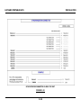
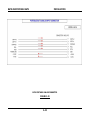
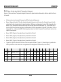
Record BATS Configuration Data
BATS Transceiver Model: _______________S/N: _____________ Hydrophone Model: ______________S/N: ___________
(Frequency Band: 8-16kHz [_______]; 17-30kHz [_______]; Other __________)
Deck Cable Model: ____________________ Length: __________________
Beacon Model: _____________ S/N: _____________ Rcv Freq: ________ Xmt Freq: ________ or Xmt Code: ___________
Beacon Model: _____________ S/N: _____________ Rcv Freq: ________ Xmt Freq: ________ or Xmt Code: ___________
Beacon Model: _____________ S/N: _____________ Rcv Freq: ________ Xmt Freq: ________ or Xmt Code: ___________
Beacon Model: _____________ S/N: _____________ Rcv Freq: ________ Xmt Freq: ________ or Xmt Code: ___________
Beacon Model: _____________ S/N: _____________ Rcv Freq: ________ Xmt Freq: ________ or Xmt Code: ___________
Beacon Model: _____________ S/N: _____________ Rcv Freq: ________ Xmt Freq: ________ or Xmt Code: ___________
Beacon Model: _____________ S/N: _____________ Rcv Freq: ________ Xmt Freq: ________ or Xmt Code: ___________
Beacon Model: _____________ S/N: _____________ Rcv Freq: ________ Xmt Freq: ________ or Xmt Code: ___________
IP Address of the Transceiver: 192.168.3.9
or
_____ . _____ . _____ . _____
TABLE OF CONTENTS
TABLE OF CONTENTS ...................................................................... i
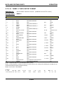
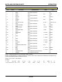
GLOSSARY OF TERMS ....................................................................iv
PRECAUTIONS ............................................................................... vi
SECTION
1.
PAGE
GENERAL INFORMATION .......................................................................... 1-1
1.1
LIST OF TYPICAL BATS EQUIPMENT .......................................................................1-4
1.2
DESK TOP SYSTEM SPECIFICATIONS ................................................................... 1-13
1.3
PORTABLE SYSTEM SPECIFICATIONS ................................................................... 1-17
2.
INSTALLATION ......................................................................................... 2-1
2.1
HYDROPHONE/INTERROGATOR INSTALLATION .......................................................2-1
2.1.1
4213C SUGGESTED HYDROPHONE MOUNTING ASSEMBLY ....................................2-2
2.1.2
ATTACHING HYDROPHONE TO ANGLE MOUNT .....................................................2-3
2.1.3
4213C-B SUGGESTED MTG FOR SEALED SHAFT INSTALLATION .......................... 2-12
2.2
BATS DESK TOP CONSOLE (TRANSCEIVER) .......................................................... 2-17
2.2.1
BATS - LINE VOLTAGE (IEC CONNECTOR) ......................................................... 2-17
2.2.2
BATS - ETHERNET CABLE WIRING (BETWEEN BATS & PC) .................................. 2-18
2.2.3
BATS - HYDROPHONE CABLE........................................................................... 2-18
2.2.4
BATS – RACK MOUNT PC AND KEYBOARD/DISPLAY ........................................... 2-18
2.2.4.1
VIDEO (PC to KYBD/DISPLAY)................................................................... 2-18
2.2.5
BATS – COM#1 CABLE WIRING (RESERVED FOR GPS TIME, 4450A) .................... 2-18
2.2.6
BATS - COM#2 COMPASS NMEA INPUT ............................................................ 2-22
2.2.7
BATS - COM#3 PITCH/ROLL NMEA INPUT ......................................................... 2-23
2.2.8
BATS - SYNCHRONIZATION INTERFACE............................................................ 2-24
2.2.8.1
INPUT TRIGGER ...................................................................................... 2-24
2.2.8.2
TRIGGER OUT ......................................................................................... 2-25
2.2.9
BATS - ANALOG SENSOR INTERFACE ............................................................... 2-25
2.2.9.1
DEPTH INPUTS ........................................................................................ 2-30
2.2.9.2
ANALOG COMPASS INPUT ........................................................................ 2-30
2.2.9.3
VRU INTERFACE (MODEL 4414B) .............................................................. 2-30
i
TABLE OF CONTENTS
2.3
PORTABLE BATS TRANSCEIVER ........................................................................... 2-32
2.3.1
PORTABLE BATS LINE VOLTAGE ...................................................................... 2-32
2.3.2
PORTABLE BATS - ETHERNET CABLE WIRING .................................................... 2-35
2.3.3
PORTABLE BATS - HYDROPHONE CABLE ........................................................... 2-35
2.3.4
PORTABLE BATS – COM#1 CABLE WIRING (GPS TIME) ...................................... 2-36
2.3.5
PORTABLE BATS - COM#2 COMPASS NMEA INPUT ............................................. 2-36
2.3.6
PORTABLE BATS - COM#3 PITCH/ROLL NMEA INPUT .......................................... 2-38
2.3.7
PORTABLE BATS - SYNCHRONIZATION INTERFACE ............................................ 2-39
2.3.7.1
INPUT TRIGGER ...................................................................................... 2-42
2.3.7.2
TRIGGER OUT (NEG) ............................................................................... 2-42
2.3.8
PORTABLE BATS - ANALOG SENSOR INTERFACE ............................................... 2-42
2.3.8.1
DEPTH INPUTS ........................................................................................ 2-42
2.3.8.2
ANALOG COMPASS INPUT ........................................................................ 2-42
2.3.8.3
VRU INTERFACE (MODEL 4414B) .............................................................. 2-45
2.4
HYDROPHONE OFFSETS ..................................................................................... 2-46
2.4.1
BEARING OFFSET .......................................................................................... 2-46
2.4.2
HYDROPHONE X AND Y OFFSETS AND HYDROPHONE DEPTH ............................... 2-50
2.4.3
HYDROPHONE-VRU OFFSET ............................................................................ 2-53
2.5
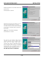
SOFTWARE INSTALLATION ................................................................................. 2-55
2.5.1
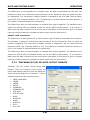
INSTALLATION FROM CD ................................................................................ 2-55
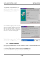
2.5.2
CALIBRATION FILES ....................................................................................... 2-58
3.
OPERATION .............................................................................................. 3-1
3.1
“TRACKMAN” SOFTWARE PHILOSOPHY ..................................................................3-5
3.2
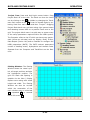
“TRACKMAN” MAIN WINDOW .............................................................................. 3-10
3.3
“TRACKMAN” MAIN & SUB-MENUS ....................................................................... 3-14
3.3.1
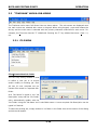
FILE MENU .................................................................................................... 3-14
3.3.2
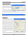
VIEW MENU .................................................................................................. 3-17
3.3.3
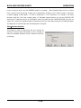
SETUP MENU ................................................................................................. 3-19
3.3.4
USBL MENU .................................................................................................. 3-52
3.3.5
WINDOW MENU ............................................................................................. 3-58
ii
TABLE OF CONTENTS
3.3.6
3.4
HELP MENU ................................................................................................... 3-59
TRACKING TRANSPONDERS, RESPONDERS AND PINGERS ...................................... 3-60
3.4.1
TRANSPONDER MODE .................................................................................... 3-61
3.4.2
RESPONDER MODE ........................................................................................ 3-63
3.4.3
FIXED (ARTIFICIAL) TARGET ........................................................................... 3-64
3.5
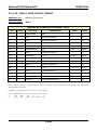
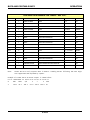
ERROR AND WARNING CODES ............................................................................ 3-69
3.6
TROUBLESHOOTING ACOUSTIC PROBLEMS .......................................................... 3-77
3.6.1
TRANSPONDER MODE .................................................................................... 3-77
3.6.2
ACOUSTIC PROBLEMS IN RESPONDER MODE .................................................... 3-79
3.7
3.7.1
HARDWARE ................................................................................................... 3-80
3.7.2
TRACKMAN (PC) RS-232 DATA OUTPUT FORMATS ............................................. 3-81
3.8
4.
4.1
5.
RS-232C INTERFACE, BATS TRANSCEIVER ........................................................... 3-80
3.7.2.1
“PORE” DATA OUTPUT PARAMETER DESCRIPTION ....................................... 3-82
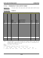
3.7.2.2
“POREB” DATA OUTPUT FORMAT ............................................................... 3-84
3.7.2.3
“POREG” DATA OUTPUT FORMAT ............................................................... 3-87
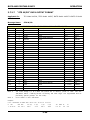
3.7.2.4
“TTM” DATA OUTPUT FORMAT ................................................................... 3-92
3.7.2.5
“STANDARD” DATA OUTPUT FORMAT ......................................................... 3-93
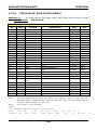
3.7.2.6
“STANDARD-EC” DATA OUTPUT FORMAT .................................................... 3-94
3.7.2.7
“STD W/PR” DATA OUTPUT FORMAT .......................................................... 3-96
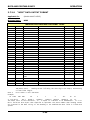
3.7.2.8
“STD-EC W/PR” DATA OUTPUT FORMAT ..................................................... 3-97
3.7.2.9
“NCSC” DATA OUTPUT FORMAT................................................................. 3-99
3.7.2.10
“REV-4” DATA OUTPUT FORMAT .............................................................. 3-100
3.7.2.11
“NUWC-1” DATA OUTPUT FORMAT........................................................... 3-102
3.7.2.12
RS-232 PARAMETER DESCRIPTION .......................................................... 3-105
3.7.2.13
TRACKMAN REMOTE INTERFACE ............................................................. 3-107
3.7.2.14
NCSC COMMAND STRUCTURE ................................................................. 3-107
SHUTDOWN .................................................................................................... 3-115
PRINCIPLES OF OPERATION .................................................................... 4-1
HYDROPHONE .....................................................................................................4-6
SYSTEM MAINTENANCE ............................................................................ 5-1
iii
TABLE OF CONTENTS
5.1
CALIBRATION FILES ............................................................................................5-1
5.2
FUSE REPLACEMENT (RACKMOUNT) ......................................................................5-2
5.2.1
PRINTED CIRCUIT BOARD (PCB) REMOVAL/REPLACEMENT ...................................5-2
5.2.2
PCB HANDLING ...............................................................................................5-2
5.3
PROCESSOR MODULE (PC) ...................................................................................5-3
APPENDIX-A CARE OF CABLES ........................................................................... 1
APPENDIX-B ELECTROSTATIC DISCHARGE (ESD) .............................................. 1
APPENDIX-C WARRANTY STATEMENT ............................................................... 1
APPENDIX-D DRAWINGS ................................................................................... 1
APPENDIX-E ORE M-FSK WAVEFORMS ............................................................... 1
iv
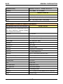
GLOSSARY OF TERMS
NAME
Azimuth
DESCRIPTION
Typically used when referencing a target position with respect to North or a
compass heading. (Could also refer to a compass heading referenced to
north.)
BATS
Stand for Broadband Acoustic Tracking System. EdgeTech’s Model 4460C or
4461C USBL Tracking System. A Spread Spectrum, high accuracy, USBL
Tracking System. For survey quality underwater navigation.
Beacon
Any underwater sound source. Sometimes abbreviated as "BCN".
Bearing
Typically used when referencing target position with respect to local coordinates, for example with respect to the hydrophone or vessel bow.
Broadband
A signaling method in which the frequency is spread across a wider band.
This would typically provide for higher data rates in communications but in
the case of the BATS provides for improved detection and higher noise rejection.
Consecutive
Tracking of more than one target by alternating (cycling through) the inter-
Tracking
rogation signals between all of the targets.
Depression An-
The downward angle measured from the plane of the hydrophone receive
gle
elements to the target. (0 deg. to 90 deg.)
Horizontal
The distance from the hydrophone or offset point to the target on the X, Y
Range
plane. (plan view)
Hydrophone
An underwater listening device.
Interrogate
To cause a response from an underwater device such as a transponder.
IPS
IPS is a Windows® based program that interfaces to DGPS and Trackman
for lat/long positioning. (Integrated Positioning System)
Pinger
An underwater sound source which transmits at a fixed preset rate, asynchronously to a tracking device. (Not available on BATS.)
RS-232 Inter-
A standard interface for serial communications.
face
Responder
An underwater sound source which responds to an electrical signal (interrogated via a hardwired link) and returns with an underwater acoustic reply.
Sometimes abbreviated as "RSPDR".
Simultaneous
Ability to track more than one target at the same time, either by triggering
Tracking
synchronously or asynchronously as long as the replies do not arrive at the
v
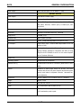
GLOSSARY OF TERMS
hydrophone at the same time.
Slant Range
The range from a target to the listening hydrophone. (Computed by the
travel time from target to hydrophone multiplied by the speed of sound in
water.)
Telemetering
Can either be a transponder or a responder. It outputs two replies in re-
Beacon
sponse to an interrogation. The first reply is the navigation pulse for the
BATS and the second reply is the telemetry pulse. The time delay between
the two replies is proportional to the sensor output on the telemetry beacon.
Trackman
EdgeTech’s Windows® based USBL Interface Software. Communicates with
the BATS Transceiver to allow modification of the target & system parameters and also outputting of processed data to Navigation packages.
TrackPoint 3
EdgeTech’s Model 4450A USBL Tracking System. A high accuracy survey
quality acoustic navigation system.
Transponder
An underwater sound source which responds to an underwater signal (device is interrogated acoustically) and returns with an underwater acoustic
reply. Sometimes abbreviated as "XPDR".
Turn Around
A preset time delay, built into a transponder or responder, between when a
Time
device is interrogated and when it replies. The delay is calibrated at the
xponder to compensate for variations in receiver propagation delays.
USBL
Ultra Short BaseLine - A type of acoustic navigation system which utilizes an
array of receiving elements spaced very close together (within inches). (As
opposed to Long Baseline Systems)
VRU
Vertical Reference Unit - Used to compensate for pitch and roll motion of the
ship.
X
The port (-) to starboard (+) direction which the target is referenced to
(e.g., bow of vessel or north).
Y
The aft (-) to bow (+) direction which the target is referenced to. (e.g., bow
of vessel or north)
Z
The targets depth. Referenced from the plane of the hydrophone elements
or offset point to the target.
vi
PRECAUTIONS
A "NOTE" message is used to emphasize a certain operation or condition.
NOTE: "____________________________________________________________."
A "CAUTION" message is noted where an operational hazard to the equipment could exist.
CAUTION
A "WARNING" is used where an injurious or life threatening condition to an operator, installer or
troubleshooter could occur.
************* WARNING *** *********
NOTE: Routinely this system is a commercial target tracking system and should not be used as a
life saving device with manned submersibles.
EdgeTech, 4 Little Brook Road, West Wareham, MA 02576 USA
Phone: 508-291-0057
Fax: 508-291-2491
http://www.edgetech.com
Copyright ©2012 EdgeTech
All Rights Reserved
vii
PRECAUTIONS
viii
SECTION ONE
GENERAL INFORMATION
BATS
GENERAL INFORMATION
The Model 4460C has the same features and functions as the 4460B but internally has a new CPU
and IDE interface. These new components allow for faster data processing with reduced stress on
the internal CPU.
1.
GENERAL INFORMATION
The EdgeTech Broadband Acoustic Tracking System (BATS) is an Ultra Short BaseLine (USBL) underwater tracking/navigation system. The O EdgeTech BATS consists of a hull mounted Transducer
(Model 4213C-B), that is both a listening Hydrophone and an Interrogator, a Deck Cable (Model
4113C), Transceiver (Model 4460C) and a PC (Customer or EdgeTech Supplied).
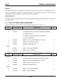
For a complete system from EdgeTech the BATS topside electronics are available in a 19-inch rack
type enclosure1. It consists of three 2U rack modules in a 6U Equipment Case containing the Transceiver (Model 4460B), the Rack Mount PC (running Windows) (Model 4451A) and a Keyboard/Display (Model 4452A). See Figures 1-1 and 1-2. The Transceiver is also available as a Desk
Top version (a 3.5 inch high chassis, 2U rack height), with a Laptop PC (EdgeTech or Customer
supplied). Another configuration of the BATS is a Portable version (Model 4461A) with a Laptop PC
(EdgeTech or Customer supplied). The Human Machine Interface (HMI) software (installed on the
PC) is called “Trackman”.
Transceiver
The Transceiver, Model 4460C, is the heart of the BATS. It is an integrated, Ultra-Short BaseLine
(USBL) acoustic signal processor designed to operate with up to four targets for a wide range of
subsea navigation and relocation tasks. It is contained in a 2U rack mount chassis and interfaces to
the Hydrophone/Interrogator and also the PC (running Windows software). The Transceiver Module
contains a receiver, digitizer and CPU along with a data acquisition module for external interface to
NMEA and analog sensors. It also contains the transmitter and power supplies. The Transceiver receives signals from the Transducer’s three element listening array (Hydrophone) and also Transmits
signals to its interrogation element.
The Transceiver interfaces to the EdgeTech USBL Hydrophone Model 4213C-B via its deck cable
Model 4113C. The Transceiver receives the signals from the Transducer and sends the raw data to
the PC for calculation of target position. The target types consist of transponders or responders
(Beacons).
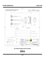
Transducer (Hydrophone/Interrogator)
The Transducer, Model 4213C-B, is 2.875 inches (7.3cm) diameter by 17.53 inches (44.53cm) in
length and is calibrated in the 17 to 30kHz frequency band for the receiver and tuned to 15 to
23kHz for the transmitter. The Model 4213C-B-LF is the same size but is calibrated in the 8 to
1
* The 19-inch rack is a standard from EIA 310-D, IEC 60297 and DIN 41494 SC48D. One “Unit” in
a rack is 1.75 inches tall, 2U is 3.50 inches etc. The 19-inches refers to the rack width.
1-1
BATS
GENERAL INFORMATION
16kHz frequency band for the receiver and tuned to 12 to 17kHz for the transmitter.
For the
4213C-B-V1634, which is larger (4.5 inches diameter X 17.5” Long) and has a lower frequency interrogation element , the transmission is tuned in the 10-14kHz band.
Keyboard/Mouse and Display
The Keyboard & LCD Monitor (Model 4452A) are an integrated unit packaged in a 2U (3.5 inch
height) rack mount chassis. The LCD monitor and Keyboard are on rack slides which lock in the out
position. The LCD monitor is on friction hinges and can be positioned at any angle. The Keyboard/Mouse provide user interface to the Trackman program.
Computer
The Rack Mount PC (Model 4451A) is a 2U chassis containing a P4 Processor (minimum), Windows® XP operating system and the Trackman (Human-Machine Interface, (HMI)) software. The
“Trackman” software is EdgeTech’s Windows® based USBL user-interface software. Trackman
communicates with the BATS’ USBL Processor Module to allow modification of the target & system
parameters and also outputting of processed USBL data to Navigation software such as the
EdgeTech IPS software. The PC (Model 4451A) communicates with the USBL Processor Module
(Model 4460B) via its Ethernet port. The PC sends commands / parameter setup data to the USBL
Processor Module and receives raw beacon-position data from the USBL Processor Module. The PC
sends formatted beacon position data out its RS232 ports to interface to a Navigation System or
the case of the IPS software it can connect internally via an IP address and port#.
Trackman Software
The “Trackman” software is EdgeTech’s Windows® based USBL user-interface software. Trackman
communicates with the BATS’ USBL Processor Module to allow modification of the target & system
parameters and also outputting of processed USBL data to Navigation software such as the
EdgeTech IPS software.
IPS Software
The IPS software integrates the USBL data and the DGPS data to display and output tracked target
data relative to Latitude and longitude. The IPS is a Windows® based software and can be installed
on the same PC as the Trackman software.
Compatibility with older Trackpoint Systems
Beacons - The BATS can track the older Legacy beacons but with no improvement in range or accuracy from the older Trackpoint systems.
Hydrophone & Amplifier/VRU Model 4211A & 4740A from TP2 or 3 – Requires re-calibration of Hydrophone and modification to the 4740A Amplifier/VRU. Can use same Deck Cables, Model 4110B.
(Contact EdgeTech for more information.)
Hydrophone Model 4213C from TP3P - Requires re-calibration of Hydrophone. Can use same Deck
Cable, Model 4113C.
1-2
BATS
GENERAL INFORMATION
Hydrophone Model 4610B – Not Compatible.
1-3
BATS
GENERAL INFORMATION
Beacons
The Model 4370A series of beacons are compatible with the BATS. They can be configured for Transponder or Responder operation. They typically output a 10ms discrete chirp signal. This means that
the composite signal is made up of a series of discrete frequencies.
External Sensors
The EdgeTech MRU (Motion Reference Unit) Model 4760B provides dynamic pitch and roll compensation for the BATS.
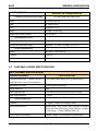
1.1
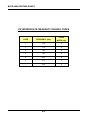
LIST OF TYPICAL BATS EQUIPMENT
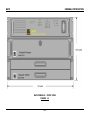
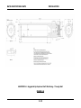
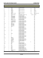
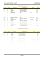
A typical Rack Mount BATS consists of the following equipment. See Figure 1-3.
ITEM
PART NUMBER
DESCRIPTION
QTY
(1) MODEL 4460C BATS USBL TRANSCEIVER MODULE
1
Shipboard:
1.
0003222
(1) MODEL 4451A PC
(1) MODEL 4452A KEYBOARD/LCD MONITOR
(1) RACK ENCLOSURE
2.
0007978
MODEL 4213C-B HYDROPHONE (17-30 kHz)
1
3.
0002935
MODEL 4113C-DT DECK CABLE
1
4.
0009638
MOTION REFERENCE UNIT
1
5.
0009612
MODEL 4370A MULTIBEACON
1
6.
0007968
MODEL 4324C CHARGER
1
Subsea:
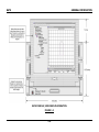
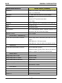
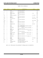
or… System configured as a desk top unit with customer furnished Laptop or PC. See Figure 1-4.
ITEM
PART NUMBER
DESCRIPTION
QTY
Shipboard:
1.
0003221
(1) MODEL 4460C BATS USBL PROCESSOR MODULE
1
2.
0007978
MODEL 4213C-B HYDROPHONE (17-30 kHz)
1
3.
0002935
MODEL 4113C-DT DECK CABLE
1
4.
0009638
MOTION REFERENCE UNIT
1
5.
0009612
MODEL 4370A MULTIBEACON
1
6.
0007968
MODEL 4324C CHARGER
1
Subsea:
1-4
BATS
GENERAL INFORMATION
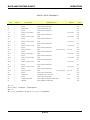
or… Portable System with customer furnished Laptop or PC. See Figure 1-5.
ITEM
PART NUMBER
DESCRIPTION
QTY
Shipboard:
1.
0003223
(1) MODEL 4461A PORTABLE BATS TRANSCEIVER
1
2.
0007978
MODULE
MODEL 4213C-B HYDROPHONE (17-30 kHz)
1
3.
0002935
MODEL 4113C DECK CABLE
1
4.
0009638
MOTION REFERENCE UNIT
1
5.
0009612
MODEL 4370A MULTIBEACON
1
6.
0007968
MODEL 4324C CHARGER
1
Subsea:
1-5
BATS
GENERAL INFORMATION
BATS CONSOLE - FRONT VIEW
FIGURE 1-1
1-7
BATS
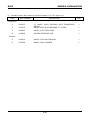
GENERAL INFORMATION
BATS CONSOLE, VIEW WHEN IN OPERATION
FIGURE 1-2
1-8
BATS
GENERAL INFORMATION
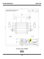
BATS COMPONENTS
FIGURE 1-3
1-9
BATS
GENERAL INFORMATION
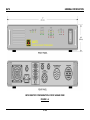
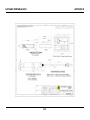
BATS DESKTOP CONFIGURATION: FRONT & REAR VIEW
FIGURE 1-4
1-10
BATS
GENERAL INFORMATION
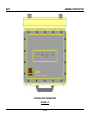
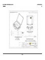
PORTABLE BATS TRANSCEIVER
FIGURE 1-5
1-11
BATS
GENERAL INFORMATION
PORTABLE BATS TRANSCEIVER SIDE PANEL
FIGURE 1-6
1-12
BATS
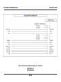
1.2
GENERAL INFORMATION
DESK TOP SYSTEM SPECIFICATIONS
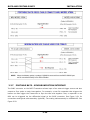
BATS DESK TOP OR RACK MOUNT SPECIFICATIONS
SYSTEM ACCURACY
Transponder/Responder - Absolute Accuracy in
SPECIFICATION
0.5% RMS of Slant Range (Does not include motion.)
Horizontal Position (over entire hemisphere)
Repeatability Accuracy
Angular Resolution
0.25% RMS of Slant Range
0.08°
Slant Range Accuracy
0.3 meter RMS (assuming correct speed of sound)
Slant Range Resolution
0.1 meter
RECEIVE SIGNAL SPEC
Frequency
MF Range; 17-30kHz or LF Range; 8-16kHz
Signal Coding Structure
Various CW, Chirp (linear), Chirp (stepped or discrete
tones), PSK Phase Shift Keying), M-FSK (Multiple - Frequency Shift keying) , (Hydroid’s REMUS (codes 1-4)
Signal to Noise Ratio required
Typically >20dB (in 17-30kHz band or 8-16kHz band)
TRANSCEIVER MODULE
Processor(s)
MODEL 4460C (19” Rack Mount)
mPGA 478 Socket, Intel Celeron M/Pentium M processor w/ FSB400MHz
RS232 Ports
3 - COM1: GPS Time, COM 2 & 3: P/R & Compass
Chassis
2U rack Height, Black
Dimensions
W 18.9” (48 cm) x H 3.46” (8.8 cm) x D 20” (50.8 cm)
Weight
21 lbs
Power
115/230 VAC, 60 W
Sub-assemblies
DSP, Target Acquisition Module, Peripheral Interface Card,
Transmitter, SBC, IDE, A2D & Power Supply
Sequential Tracking
Up to 4 Targets
DIFF KEY INPUT – RESPONDER (4)
Via rear panel Synchronization connector
Accepts single ended or differential signal input to an optocoupler.
pulse widths min = 200 micro-seconds
pulse width max = up to the width of the transmit-out burst
1-13
BATS
GENERAL INFORMATION
TRIGGER OUT
Via rear panel Synchronization connector
Sync for Responder operation;
Differential Output (0-5VDC) Either side can be used as a
positive or negative TTL pulse when used with GND.
ANALOG INPUTS
Analog Voltage input for Depth
Uni-polar 0-6VDC
Analog Voltage input for Compass
Uni-polar 0-6VDC
Analog Voltage input for Pitch & Roll
±10VDC input
Absolute Accuracy (±10VDC, -10 to 50C)
0.27%
Resolution of A/D Converter
A/D converter = 16-bits
RS-232 PORTS
Comport #1
GPS Time Input – ZDA or GGA
Comport #2
Compass Input, typically
Comport #3
Pitch/Roll Input, typically
1-PPS INPUT
Via rear panel BNC
Accepts a 1-PPS trigger from GPS; Opto-coupler input. Requires ZDA and GGA input also.
ETHERNET
Via Rear Panel Connector
Provides communications with PC (Data & Commands)
TRANSMITTER SPECS
Frequency
MF: 15-23kHz, LF: 13-17kHz
Pulse Width
1-15ms in 0.1 ms increments
Repetition Rate
0.5 to 60 seconds
Signal Coding Structure
Various – CW, Chirp (linear), PSK, FSK, REMUS (codes 1-4)
Output Power
100 or 400 Watts into 300 Load
Sound Pressure Level
MF: 17-20kHz, @ 400W - Nominal 192dB re 1Pa @ 1m
(Hydrophone Interrogator)
LF: 13-17kHz, @ 400W - Nominal 192dB re 1Pa @ 1m
HYDROPHONE/INTERROGATOR
MODEL 4213C-B
Diameter
2.9 inches (7.4 cm)
Height
19.4 inches (49.3 cm)
Weight
10 lbs (4.5kg)
1-14
BATS
GENERAL INFORMATION
Temperature Rating
Operating: -4° to 40° C
Frequency
MF: 17-30kHz
DECK CABLE
Storage: -40° to 70° C
or LF: 8-16kHz
MODEL 4113C-DT
Length
50ft (15m) or 100ft (30m)
Diameter
Dry End: 2.35 in (6cm) Wet End: 1.38 in (3.5cm)
Weight
50ft - 7 lbs (3.2kg) or 100ft - 14 lbs (6.4kg)
RACK MOUNT SYSTEM OPTIONAL COMPONENTS
KEYBOARD/MOUSE/LCD MODULE
MODEL 4452B
Interfaces with PC for Communication and Display. (Runs EdgeTech’s Trackman Software
which interfaces with the BATS.)
LCD Panel
17" LCD panel
Display type
TFT/LCD active matrix color
Display Area
304.1mm(H) x 228.1mm(V)
Viewing angle
130o (Horiz.)/110o (Vert.)
Resolution
1024 x 768
Contrast ratio
300:1 typical
Brightness
250 cd/m2 typical
Pixel pitch
0.297mm (H) x 0.297mm (W)
Panel color
16.7 million display colors
Back Light
4 CCFTs (Cold Cathode Fluorescent tube)
Synchronization Range
Horizontal: 48.36-60 KHz; Vertical: 56-75 KHz
Storage temp.
-25ºC to 60ºC
Operating temp.
0ºC to 50ºC
MTBF
35,000 hours
Video Input Signal
Analog RGB 0.7Vp-p
Video Input Conn
15-pin D-Sub connector
Chassis
2U rack Height, Black
Dimension
W 17.3” (44 cm) x H 3.46” (8.8cm) x D 23.7” (60.2 cm)
Weight
30 lbs (13.6 kg)
1-15
BATS
Power supply:
GENERAL INFORMATION
110V 220V AC Input, 12V 5A Output (75W)
PC
MODEL 4451A
Power Supply
300 Watt ATX Power Supply
Processor
Minimum: Intel P4- 1GHz Socket 370
Single Board Computer
Socket 370 Single Board Computer, P4, 100MHz FSB, w/
AGP Video, Ethernet, 2-RS232 ports, 1-Parallel port, PS2Key\Mouse
Memory
Minimum: 1GB
Hard Drive
Minimum: 80 GB IDE Hard Drive, 7200 RPM
Floppy Drive
1.44 MB, 3 1/2"
CD/DVD Drive
56X CD-R0M, R/W DVD
RS232 Ports
4 total (Baud Rates adjustable from 2400 to 115k)
For Example…
Depth Sensor Input – Receive NMEA depth data from a Tow
Vehicle or ROV.
…or
Tracking Data Output – Send Tracked Target data to a Navigation Software package for integration with GPS. (If using
EdgeTech’s IPS software it can run on this same computer
as the Trackman Software.
Parallel Port
1
Operating System
MS Windows XP Professional
Ethernet Port (1)
Communication with BATS Transceiver (Rack Mount or Portable)
Chassis
Industrial 2U Rack Height, Black, Fan & Filter, Front door
protects disk drives Front panel supports keylock and power
switch, reset button & keyboard connector Automatic fanfailure detection
Dimensions
W 18.9” (48cm) x H 3.4” (8.6cm) x D 17.1” (43.4cm)
Weight
Approx. 25 lbs
Power
115/230 VAC, 200 W
Shock
10 G acceleration peak to peak (11 ms)
Vibration
5~17Hz, 0.1 ”double amplitude displacement; 17~640Hz,
1.5 G acceleration peak to peak
1-16
BATS
GENERAL INFORMATION
MISCELLANEOUS
XCEIVER, PC, KEYBD DISPLAY
CONSOLE PHYSICAL SPECIFICATIONS
NOT INCLUDING RACK ENCLOSURE
Height
10.5 inches (26.7cm)
Width
17 inches (43 cm)
Depth
20 inches (51 cm)
Weight
Estimate : 95 lbs (43kg)
Weight with 6U Rack Enclosure
107 lbs (48.5)
ENVIRONMENTAL SPECS
BATS Console Temperature Rating
Operating: 0° to 50° C; Storage: -25° to 60° C
Hydrophone Temperature Rating
Operating: -4° to 40° C, Storage: -40° to 70° C
POWER REQUIREMENTS
Voltage
115-230 AC (auto switching)
Frequency
50-60 Hz
Power
325 Watts
1.3
PORTABLE SYSTEM SPECIFICATIONS
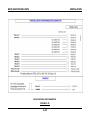
BATS PORTABLE SPECIFICATIONS
SYSTEM ACCURACY
Transponder/Responder - Absolute Accuracy in
SPECIFICATION
0.5% RMS of Slant Range (Does not include motion.)
Horizontal Position (over entire hemisphere)
Repeatability Accuracy
Angular Resolution
0.25% RMS of Slant Range
0.08°
Slant Range Accuracy
0.3 meter RMS (assuming correct speed of sound)
Slant Range Resolution
0.1 meter
RECEIVE SIGNAL SPEC
Frequency
MF Range; 17-30kHz or LF Range; 8-16kHz
Signal Coding Structure
Various CW, Chirp (linear), Chirp (stepped or discrete
tones), PSK Phase Shift Keying), M-FSK (Multiple - Frequency Shift keying) , (Hydroid’s REMUS (codes 1-4)
Signal to Noise Ratio required
Typically >20dB (in 17-30kHz band or 8-16kHz band)
1-17
BATS
GENERAL INFORMATION
TRANSCEIVER MODULE
Processor(s)
MODEL 4461C (Portable)
mPGA 478 Socket, Intel Celeron M/Pentium M processor w/ FSB400MHz
RS232 Ports
3 - COM1: GPS Time, COM 2 & 3: P/R & Compass
Enclosure
Watertight
Material: HPX® High Performance Resin
Color: Yellow
Dimensions
W 19.2” (48.8 cm) x H 7.3” (18.5 cm) x D 15.2” (38.6 cm)
Weight
23.5 lbs (10.7 kg)
Power
115/230 VAC, 60 W
Sub-assemblies
DSP, Target Acquisition Module, Peripheral Interface Card,
Transmitter, SBC, IDE, A2D & Power Supply
Sequential Tracking
Up to 4 Targets
DIFF KEY INPUT – RESPONDER (4)
Via rear panel Synchronization connector
Accepts single ended or differential signal input to an optocoupler.
pulse widths min = 200 micro-seconds
pulse width max = up to the width of the transmit-out burst
TRIGGER OUT
Via rear panel Synchronization connector
Sync for Responder operation;
Differential Output (0-5VDC) Either side can be used as a
positive or negative TTL pulse when used with GND.
ANALOG INPUTS
Analog Voltage input for Depth
Uni-polar 0-6VDC
Analog Voltage input for Compass
Uni-polar 0-6VDC
Analog Voltage input for Pitch & Roll
±10VDC input
Absolute Accuracy (±10VDC, -10 to 50C)
0.27%
Resolution of A/D Converter
A/D converter = 16-bits
RS-232 PORTS
Comport #1
GPS Time Input – ZDA or GGA
Comport #2
Compass Input, typically
Comport #3
Pitch/Roll Input, typically
1-18
BATS
GENERAL INFORMATION
1-PPS INPUT
Via rear panel BNC
Accepts a 1-PPS trigger from GPS; Opto-coupler input. Requires ZDA and GGA input also.
ETHERNET
Via Side Panel Connector
Provides communications with PC (Data & Commands)
TRANSMITTER SPECS
Frequency
MF: 15-23kHz, LF: 13-17kHz
Pulse Width
1-15ms in 0.1 ms increments
Repetition Rate
0.5 to 20 seconds
Signal Coding Structure
Various – CW, Chirp (linear), PSK, FSK, REMUS (codes 1-4)
Output Power
100 or 400 Watts into 300 Load
Sound Pressure Level
MF: 17-20kHz, @ 400W - Nominal 192dB re 1Pa @ 1m
(Hydrophone Interrogator)
LF: 13-17kHz, @ 400W - Nominal 192dB re 1Pa @ 1m
HYDROPHONE/INTERROGATOR
MODEL 4213C-B
Diameter
2.9 inches (7.4 cm)
Height
19.4 inches (49.3 cm)
Weight
10 lbs (4.5kg)
Temperature Rating
Operating: -4° to 40° C
Frequency
MF: 17-30kHz
DECK CABLE
Storage: -40° to 70° C
or LF: 8-16kHz
MODEL 4113C
Length
50ft (15m) or 100ft (30m)
Diameter
1.38 in (3.5cm)
Weight
50ft- 7 lbs (3.2kg) or 100ft - 14 lbs (6.4kg)
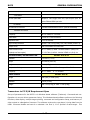
Transceiver to PC S/W Requirement Spec
Set up of parameters for the BATS is via Windows based software (Trackman). Command and configuration via a menu driven parameter listing. This Windows based software performs the following
functions, data display, multiple target plotting, command and configuration setup, and beacon position output to a Navigation Processor. The software receives the raw phase / timing data from the
USBL Processor Module and uses it to calculate the final X, Y & Z position of each target. This
1-19
BATS
GENERAL INFORMATION
calculated position is typically sent to a Navigation software package / processor for positioning of
targets in latitude /longitude coordinates.
OPTIONAL:
MRU
MODEL 4760B
Material
Aluminum Silicon Bronze
Connector
Subconn MCBH6M
Temperature
-4° to 40°C
Pressure Depth
2000 meters
Input Voltage
8 to 30 VDC
Input Power
0.75 Watts
Communications
RS232
Baud Rate
38.4 or 115.2k baud
Output Rate
up to 32 updates per second
Output Sentence
$POREM Format
1-20
SECTION TWO
INSTALLATION
BATS AND PORTABLE BATS
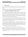
2.
INSTALLATION
INSTALLATION
This section includes instructions for implementing a 4213C Hydrophone mounting assembly, making proper attachment of the 4113C Deck Cable and also the Transceiver side panel interface connections.
Hydrophone bearing, X, Y, Z offsets and pitch/roll offsets are generally determined at the time of
installation. This section includes sample procedures for determining those offsets.
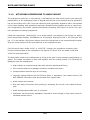
2.1
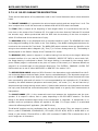
HYDROPHONE/INTERROGATOR INSTALLATION
The manner and location in which the hydrophone assembly is mounted on the vessel is the single
most crucial element in the overall performance of the tracking system. In choosing a mounting
location, the operator should keep in mind that the BATS is by nature an extremely sensitive
acoustic system.
The hydrophone assembly must be in a position to "hear" the acoustic pulses
coming from the pinger, transponder, or responder in use. Mount the hydrophone as far as possible from noise sources, such as, propellers, thrusters, echo-sounder transducers, main engines,
generators and other underwater acoustic generating systems.
Ideally, the hydrophone should be mounted far enough from the nearest reflector to allow the direct arrival of a signal from the acoustic source before a reflected signal arrives. The minimum
recommended distance between the hydrophone array and the nearest reflector (which is usually
to the vessel's hull or keel) is one meter*. It is also important to keep the hydrophone below the
level of the vessel's keel for 360-degree coverage.
System performance can be degraded by "multi-path" or underwater signal reflections and reverberation. To minimize the possible effects of multi-path, choose a hydrophone location that is as far
away as possible from any surface that would make a good reflector of an acoustic pulse. Any hard
plate or structure near the hydrophone has the potential to reflect pulses into the hydrophone. The
air-water interface is also an extremely efficient acoustic reflector. Avoid any mounting locations
that would place the hydrophone in the proximity of bubbles.
*
1 meter = (1.33 milliseconds x 1500 meters/second) 2 way travel time
Consult the nearest EdgeTech representative for additional information on a specific installation.
NOTE: In some applications even though the hydrophone is over one meter directly away from the
hull, a signal can be reflected from an area along the keel and arrive within 1.3 ms of the direct
arrival thus causing interference. In these instances the hydrophone should be lowered further
away from the hull.
2-1
BATS AND PORTABLE BATS
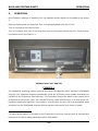
2.1.1
INSTALLATION
4213C SUGGESTED HYDROPHONE MOUNTING ASSEMBLY
The main function of the mounting assembly is to support the hydrophone vertically in the water
and orient it with respect to the bow of the vessel. See Figure 2-1 for Hydrophone dimensions.
Mount it at reasonable distance from the vessel's hull and below the level of the keel. The mounting should be rugged enough to withstand the expected forces during the planned operation, and
easy to raise and lower. The type and size of the mounting recommended for the BATS Hydrophone varies with the size of the surface vessel and the intended application.
Transiting to/from operating locations with the hydrophone deployed is not recommended.
In general, consider the following when designing the hydrophone mounting.
1.
The mounting pipe should be long enough to position the hydrophone below the vessel keel when in the vertical position.
2.
The pipe used should be stiff enough to prevent vibration or strumming when the
vessel is underway.
3.
Attach the pipe to the side of the vessel so that the pipe and hydrophone assembly
can be easily removed and set on board, if required, to tie the vessel up alongside
other vessels or at dockside.
4.
The entire assembly should be easy to raise and lower with available manpower or
winches.
5.
Hydrophone heading (referenced by the index mark) should align with vessel heading. The mount should be fabricated to allow the rotation of the hydrophone to correct for any bearing misalignment during installation (see section 2.4.1 Bearing Offset Adjustment). Some locking arrangement should be used to maintain the calibrated bearing.
6.
Forward and aft guys are used to hold the mounting pipe in vertical position.
See Figure 2-2 for example of mounting arrangement.
The Model 4213C Hydrophone can be mounted to an angle bracket which mounts to the end of a
suitable length of pipe or assembled into a machined end of pipe or shaft. Choose the size and material of the pipe according to the application. The Hydrophone can survive up to 10knots as long
as shaft/pipe does not strum or vibrate.
2-2
BATS AND PORTABLE BATS
2.1.2
INSTALLATION
ATTACHING HYDROPHONE TO ANGLE MOUNT
The hydrophone centerline, or zero bearing, is indicated by the index mark (mark is just above the
potted section of the hydrophone which is aligned with the slot in the pressure case as opposed to
the pin which faces aft or 180 from bow reference) and is generally aligned so that it corresponds
to the vessel heading. Most operations requiring a portable tracking system will be on various vessels of opportunity, and require a quick and temporary mounting. See Figure 2-2 and 2-3 for a typical hydrophone mounting arrangement.
Fasten the hydrophone, Model 4213C, to an angle bracket (not supplied), (see Figure 2-4 Hydrophone Mount Angle Bracket, 4213BM0010 as an example) aligning the slot in the PVC base with
the “V” in the bracket. Using screw clamps secure the hydrophone to the proposed angle bracket.
Align the screw clamps with the grooved areas on the hydrophone case.
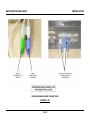
Feed the deck cable, Model 4113C or 4113C-DT, through the hydrophone extension pipe.
Connect the deck cable to the hydrophone. See Figures 2-5 and 2-6 for the Model 4113C and
4113C-DT cable assemblies.
The Deck Cable mates to the Hydrophone by lining up the pins in both connectors and pushing together. The mated connection is then held together with the locking sleeves. The following are
guidelines from the manufacturer.
Align indexes on connectors and mate with minimum twisting and flexing
Care must be taken not to damage contacts in unmated connectors
Contact surfaces must be dry prior to mating.
Lubricate mating surfaces with 3M Silicone Spray or equivalent* (see caution below). DO
NOT GREASE. Connectors must be lubricated on a regular basis.
Avoid contact with solvents.
Grip main body of connector during mating or unmating. Do not pull on the cable to disconnect.
Avoid sharp bends at cable entry to connector.
Elastomers can be seriously degraded if exposed to direct sunlight or high ozone levels for
extended periods of time.
2-3
BATS AND PORTABLE BATS
INSTALLATION
CAUTION
* When mating connectors DO NOT allow any silicone spray (or grease) to contact the
black potting of the hydrophone.
Should silicone come in contact with the hydrophone
potting, proper sound transfer from water to hydrophone will be prevented. Attempting to
remove silicone from the hydrophone can damage the potting material.
NOTE:
If you are using an extension pipe with a sufficient inside diameter to allow the hydrophone cable to be fed through to the hydrophone, remember to run the cable through the
pipe before placing the 1/2-inch (13-mm) bolts in the mounting holes, as the connector
may not pass through when the bolts are in place. When drilling the lower hole, keep in
mind that you need enough space between the end of the pipe and the connector on the
top of the hydrophone itself to connect and disconnect the cable. For this reason, we recommend that the lower mounting hole be no more than two inches (5 cm) from the end
of the pipe.
Fasten the hydrophone and angle bracket to the extension pipe. Use screw eyes or other fasteners
for fore and aft guy attachments.
Using the "V" of the angle bracket as a guide, align the hydrophone (mark is facing forward) with
the vessel centerline as closely as possible. Lock in place.
Use some variation of the procedure in 2.4.1 to remove hydrophone bearing offset.
2-4
BATS AND PORTABLE BATS
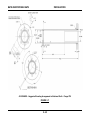
INSTALLATION
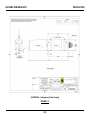
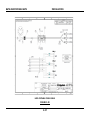
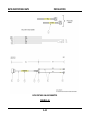
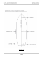
4213BE0055 – Hydrophone Outline Drawing
FIGURE 2-1
2-5
BATS AND PORTABLE BATS
INSTALLATION
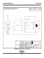
4213BE0055–V1634 Hydrophone Outline Drawing
FIGURE 2-1A
2-6
BATS AND PORTABLE BATS
INSTALLATION
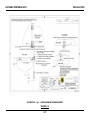
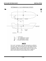
4213BE0010 – Pg 1 - HYDROPHONE MTG ARRANGEMENT
FIGURE 2-2
2-7
BATS AND PORTABLE BATS
INSTALLATION
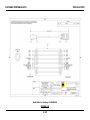
4213BE0010 - Page 2 Pipe & Angle Bracket arrangement
FIGURE 2-3
2-8
BATS AND PORTABLE BATS
INSTALLATION
4213BM0010 - Angle Bracket Drawing
FIGURE 2-4
2-9
BATS AND PORTABLE BATS
INSTALLATION
Deck Cable for Desktop, 4113BA0010
FIGURE 2-5
2-10
BATS AND PORTABLE BATS
INSTALLATION
Deck Cable for Portable, 4113BA0009
FIGURE 2-6
2-11
BATS AND PORTABLE BATS
2.1.3
INSTALLATION
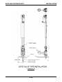
4213C-B SUGGESTED MTG FOR SEALED SHAFT INSTALLATION
The Model 4213C Hydrophone can also be installed through a hull mounted gate valve. The hydrophone is first installed in a mounting staff and the mounting staff is projected through a gate valve.
This allows for ease of deployment, recovery and maintenance of the hydrophone. Figure 2-7
(4213CM0053) shows the suggested machining dimensions necessary for mounting the hydrophone to an extension shaft (Flanged). An example of a gate valve type mounting arrangement for
Hydrophone installation is shown in Figure 2-8 (4630CM0154). A complete installation is shown in
Figure 2-9. For information on the Model 4630D Motorized Gate Valve System contact EdgeTech.
NOTE:
The slot opposite the “BOW” alignment mark in the staff is for the AFT alignment pin.
The hydrophone extension shaft must extend the hydrophone far enough from the nearest reflector, allowing the direct arrival of a signal from the acoustic source before a reflected signal arrives.
This distance is a minimum of 1 meter. It is also important to keep the hydrophone below the level
of the ship's keel for good 360 degree coverage.
When designing the hydrophone mount/deployment system keep in mind that the shaft be keyed
to allow a repeatable bearing orientation. This ensures that the bow reference always returns to
the same fixed position when the hydrophone is deployed.
The gate valve/mounting staff assembly should be installed in as close to a vertical position as possible.
The hydrophone mount can be installed offset from the centerline of the vessel. An X and Y offset
can be input to the PC to correct for these offsets. Refer to section 2.4.
The Deck Cable mates to the Hydrophone by lining up the pins in both connectors and pushing together. The mated connection is then held together with the locking sleeves. The following are
guidelines from the manufacturer.
Align indexes on connectors and mate with minimum twisting and flexing
Care must be taken not to damage contacts in unmated connectors
Contact surfaces must be dry prior to mating.
Lubricate mating surfaces with 3M Silicone Spray or equivalent* (see caution below). DO
NOT GREASE. Connectors must be lubricated on a regular basis.
Avoid contact with solvents.
Grip main body of connector during mating or unmating. Do not pull on the cable to disconnect.
Avoid sharp bends at cable entry to connector.
2-12
BATS AND PORTABLE BATS
INSTALLATION
Elastomers can be seriously degraded if exposed to direct sunlight or high ozone levels for
extended periods of time.
CAUTION
* When mating connectors DO NOT allow any silicone spray (or grease) to contact the
black potting of the hydrophone.
Should silicone come in contact with the hydrophone
potting, proper sound transfer from water to hydrophone will be prevented. Attempting to
remove silicone from the hydrophone can damage the potting material.
See Figures 2-8 and 2-9 for the Model 4113C and 4113C-DT cable assemblies.
2-13
BATS AND PORTABLE BATS
INSTALLATION
4213CM0053 - Suggested Mounting Arrangement in Machined Shaft – Flange OTS
FIGURE 2-7
2-14
BATS AND PORTABLE BATS
INSTALLATION
4450CM0154 - Suggested Hydrophone Shaft Machining – Through Hull
FIGURE 2-8
2-15
BATS AND PORTABLE BATS
INSTALLATION
FIGURE 2-9
2-16
BATS AND PORTABLE BATS
2.2
INSTALLATION
BATS DESK TOP CONSOLE (TRANSCEIVER)
The convenience and comfort of the operator are the primary considerations for installing the Desk
Top console & PC. The BATS consists of a single 2U enclosure (3.5 inches high each), configurable
for either Rack mount or Desktop operation, and couples to a Customer Furnish PC or laptop. Place
the unit where it is most conveniently operated (LED’s visible) and protected from foul weather and
sea spray. E.g., Indoors on a bench top. See Figure 1-4. Typically a Laptop can be placed on top of
the BATS Console. A typical rack mount setup for the three Modules is shown in Figure 1-1.
The system requires the following inter-connections along with a suitable power source and free
access for connecting the deck cable.
Interface connections:
Line Voltage/AC power (100-240VAC auto switching)
Ethernet from Transceiver to PC/ Laptop
Transceiver (Model 4460C) to Hydrophone Deck Cable (Model 4113C-DT)
Trigger/Sensor Interface Cable (optional)
Motion Reference Interface (Analog or RS232) (optional)
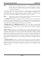
2.2.1
BATS - LINE VOLTAGE (IEC CONNECTOR)
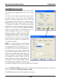
The BATS line voltage can be in the range of 98 to 132 or 170 to 264; 50 or 60 Hz. The unit automatically switches to the higher range when the voltage is sensed. If the voltage goes below the
high range minimum or 170, the system does not automatically switch to the lower range, it must
be turned off and on again. Connect the desk top unit to a suitable power source using the IEC AC
cable.
************
WARNING
************
If using an inverter to power the Deck Unit from a battery, make sure that the inverter’s ground
contact is tied to the sea water. This connects the box/chassis to the sea water potential and not
float to a dangerous potential.
2-17
BATS AND PORTABLE BATS
2.2.2
INSTALLATION
BATS - ETHERNET CABLE WIRING (BETWEEN BATS & PC)
Connect the Ethernet cable (provided) between the BATS console (rear panel) and the PC. The
Ethernet cable is 10-base-T and runs at 100MHz. A straight through cable is required (cross-over is
performed inside the BATS console).
2.2.3
BATS - HYDROPHONE CABLE
Connect the Hydrophone/Interrogator Deck Cable Model 4113C-DT (Figure 2-8) from the Hydrophone to the Transceiver Model 4460C.
The Deck Cable mates to the Transceiver by lining up the MS connector on the CABLE with the HYDROPHONE input connector on the BATS unit. Thread the collar / locking sleeve down over the
bulkhead connector on the Transceiver pushing in on the connector body while turning locking
sleeve.
2.2.4
2.2.4.1
BATS – RACK MOUNT PC AND KEYBOARD/DISPLAY
VIDEO (PC TO KYBD/DISPLAY)
Connect the “Y” cable from the Processor K/M Combo connector to the Keyboard/Display Mouse
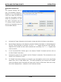
connector and Keyboard connector. The Green Keyboard/Display cable goes to the Mouse connector on the Processor’s K/M Combo cable and the Blue goes to the Keyboard connector on the Processor’s K/M Combo cable. See Figure 2-10 and 2-11.
OPTIONAL INTERFACE INTER-CONNECTS
2.2.5
BATS – COM#1 CABLE WIRING (RESERVED FOR GPS TIME, 4450A)
The COM#1 input port is only used for inputting the GPS sentences into the BATS to synchronize
the GPS time to the BATS time. Install a 9-pin (F) to 9-pin (F) communications cable between the
4460C 9-pin (M) COM1 connector to the GPS’ 9-pin (M) connector (GPS connector type may vary
between manufacturers, refer to the GPS manual for pin outs to determine if a null modem is required). See Figure 2-12 for rear panel connectors. Refer to section 3 to configure BATS for GPS
time sync.
2-18
BATS AND PORTABLE BATS
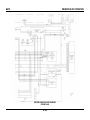
INSTALLATION
VIDEO KEYBOARD/MOUSE CONNECTIONS
FIGURE 2-10
2-19
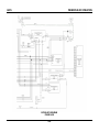
BATS AND PORTABLE BATS
INSTALLATION
RACKMOUNT PC REAR PANEL CONNECTIONS
FIGURE 2-11
2-20
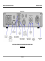
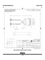
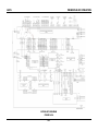
BATS AND PORTABLE BATS
INSTALLATION
BATS SIGNAL INTERFACE MODULE REAR PANEL CONNECTIONS
FIGURE 2-12
2-21
BATS AND PORTABLE BATS
2.2.6
INSTALLATION
BATS - COM#2 COMPASS NMEA INPUT
(Cable Wiring; 9-PIN MALE `D' CONNECTOR)
The Transceiver (Model 4460C) COM #2 I/O port is wired the same as a PC ("DTE", Data Terminal
Equipment). It is used for the input of NMEA compass data. See Figure below for wiring. See section 3 for NMEA formats accepted. May require a Null Modem depending on the Compass wiring.
2-22
BATS AND PORTABLE BATS
2.2.7
INSTALLATION
BATS - COM#3 PITCH/ROLL NMEA INPUT
(Cable Wiring; 9-PIN `D' CONNECTOR)
The Transceiver (Model 4460C) COM #3 I/O port is wired the same as a PC ("DTE", Data Terminal
Equipment). It is used for the input of NMEA Pitch and Roll sensors. See Figure below for wiring.
If an EdgeTech MRU is interfaced to COM#3 the wiring has been crossed-over in the MRU so that a
null modem is not required.
If the BATS is configured with the Micro-Modem option, COM #3 is used for the Modem
Communications only and COM#3 is no longer available to the BATS.
2-23
BATS AND PORTABLE BATS
2.2.8
INSTALLATION
BATS - SYNCHRONIZATION INTERFACE
The SYNC connector on the BATS Transceiver allows input of an external trigger source and also
outputs a Sync pulse on each interrogation. For example, a tow fish responder that triggers the
beacon can also trigger the Transceiver to Sync the two units together. Also, a responder on an
ROV can be triggered via the differential signal at the SYNC connector. See Figure 2-13 for
connections and Figure 2-14 (4450BA0079) for the provided cable assembly. The mating connector
is a MS3106A-20-29P.
2.2.8.1
INPUT TRIGGER
The Transceiver can be externally triggered via the “SYNC” connector located on the rear panel of
the desk top unit. A synchronization cable is provided (4450BA0079) for Trigger In, Trigger_Out1
and /Trigger_Out1. See Figure 2-14. This can be connected between an external key source (trigger source can range from TTL to +15V) and the BATS Transceiver. Connect the external trigger
between the TRIG-IN1-LO and the TRIG-IN1-HI2. The external trigger for Target #1 becomes the
master for all other targets when in this mode. All other targets switch to external mode, (via
Trackman Software) synching from the trigger #1’s source. Set the Trigger edge that you want to
trigger the unit with in the Trackman Software. See section 3.
2
NOTE:
The REMOTE-IN trigger is optically coupled.
2-24
BATS AND PORTABLE BATS
2.2.8.2
INSTALLATION
TRIGGER OUT
A synchronization cable is provided (4450BA0079) for Trigger In, Trigger_Out1 and /Trigger_Out1.
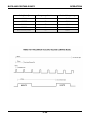
See Figure 2-10. The TRIGGER out consists of a positive going TTL pulse on one BNC and a negative going TTL pulse on another. By using both positive and negative signals, a differential TTLcompatible pulse, occurring at the time of interrogation for a transponder or a responder, is available. This TRIGGER out pulse is present simultaneously with the leading edge of each interrogation
pulse. The output can be configured as differential or positive / negative single ended when used
with the COMMON line. See Figure 2-13. The Trigger_Out4 and /Trigger_Out4 can be programmed
within the Peripheral Interface Card to either output a trigger or connect it to GND. The Gnd connection can then be used to reference any of the pos or neg triggers for single ended operation.
Jumper JP15 from 1-2 for Trigger_Out4 or 2-3 for GND. Jumper JP18 from 1-2 to output
/Trigger_Out4 or 2-3 for GND.
2.2.9
BATS - ANALOG SENSOR INTERFACE
The ANALOG input connector allows input of an analog signal from a compass, dynamic motion
sensing system, (analog pitch and roll signals from an external sensor such as the EdgeTech Model
4414B), and also the depth signal from an underwater vehicle. An interface cable is provided,
4410BA0123, for inputting analog pitch and roll sensors to the BATS. See Figure 2-15 for
connections and 2-16 for the 4410AB0123 cable Assembly. The mating connector is a MS3106B24-5S from Amphenol. The 4760B MRU uses this interface to provide +12VDC to the unit while the
RS232 connects to COM #3.
2-25
BATS AND PORTABLE BATS
INSTALLATION
SYNC INTERFACE CONNECTOR ON DESK TOP UNIT
FIGURE 2-13
2-26
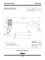
BATS AND PORTABLE BATS
INSTALLATION
SYNC INTERFACE CONNECTOR (DESK TOP CONSOLE)
FIGURE 2-14
2-27
BATS AND PORTABLE BATS
INSTALLATION
ANALOG INTERFACE CONNECTOR (DESK TOP CONSOLE)
FIGURE 2-15
2-28
BATS AND PORTABLE BATS
INSTALLATION
ANALOG INTERFACE CONNECTOR (DESK TOP CONSOLE)
FIGURE 2-16
2-29
BATS AND PORTABLE BATS
2.2.9.1
INSTALLATION
DEPTH INPUTS
The analog output voltage from a depth sensor (typically located on a vehicle being tracked) connects to the ANALOG input connector located on the rear panel of the Transceiver. See Figure 1-4.
The BATS converts this analog voltage (0 - 6 VDC maximum) to a target depth.
2.2.9.2
ANALOG COMPASS INPUT
The analog output voltage from a compass (0 - 6 VDC maximum) connects to the COMPASS input
of the ANALOG connector. See Figure 2-15. The BATS converts this analog voltage to a vessel
heading in degrees.
2.2.9.3
VRU INTERFACE (MODEL 4414B)
The VRU input of the ANALOG connector accepts PITCH and ROLL analog signals from an external
dynamic motion sensing system, such as the EdgeTech Model 4414B. The pitch and roll signals
compensate target position for vessel motion. The analog inputs can accept voltages up to +/-10
VDC. See Figure 2-16 for supplied cable assembly. The normal vessel motion for a positive Voltage
pitch is BOW UP and the normal vessel motion for a positive Voltage roll is PORT UP. The polarity of
the analog input signals to the Transceiver can be reversed and compensated for in the REMOTE
VRU POLARITY menu. Normal polarity for pitching bow up is (+) and for rolling port side up is (+).
The VRU scaling can also be modified under the REMOTE VRU SCALE menu. Normal scaling LINEAR
is 0.2 V/degree (+/- 10VDC = +/-50°). (optional scaling is 10 sin )
NOTE:
For a Remote VRU the normal voltage polarity for pitching BOW UP is [+]. The normal voltage polarity for rolling PORT UP is [+]. The system configuration software
(Trackman) shows the roll and pitch polarity [+] when the vessel pitches BOW UP or
rolls PORT UP. The RS232 Format STD W/PR (standard format with pitch and roll at
end of data string) also outputs data with this same protocol. The RS232 Format
NMEA ORE (NMEA 0183 type format string that is proprietary to EdgeTech and includes pitch and roll data at end of string) is different in that it outputs data in the
same polarity as its incoming voltage. This allows pass-through of signals from remote VRU to integrated navigation system without modification of polarities.
When using the Model 4730B VRU setup the Attitude Sensor for Internal. This automatically sets up the parameters to agree with this standard EdgeTech sensor.
Connect the pitch signal to pin-L and the roll signal to pin-S. Connect the analog commons to pinsP & R respectively.
2-30
BATS AND PORTABLE BATS
INSTALLATION
Also see the newer EdgeTech MODEL 4760B MRU. It uses MEMS technology to provide very accurate pitch and roll data. It connects to the Analog Connector for its power and to COM#3 for its
data.
2-31
BATS AND PORTABLE BATS
2.3
INSTALLATION
PORTABLE BATS TRANSCEIVER
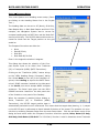
The Portable BATS Transceiver (Model 4461A) is splash proof when the case cover is closed and
interface cables are mated properly. A laptop or PC is required to interface to the unit via Ethernet
port. The Ethernet cable (4450BA0133) provided is 16 feet (5m) long (Figure 2-13). Make sure the
laptop or PC is well protected unless it is also splashproof.
The Portable BATS requires the following inter-connections along with a suitable power source and
free access for connecting the interface cables. All interface connections are made on the right side
of the unit via underwater connectors. See Figure 1-6. The ON/OFF switch and fuseholder are also
located on same panel. The system LED’s are located under the top cover. Once setup has been
completed (setup LED’s have been confirmed) the cover can be closed and the unit is extremely
splash proof.
The unit can accept input Voltages ranging from 100 to 240VAC, 50-60 Hz, and automatically
switches between the ranges.
Interface connections:
Line Voltage/AC power (100-240VAC auto switching) (Figure 2-15)
Ethernet from Transceiver to PC/ Laptop (Figure 2-13)
Transceiver (Model 446A1) to Hydrophone Deck Cable (Model 4113C) (Figure 2-7)
Trigger/Sensor Interface Cable (optional) (Figure 2-17)
2.3.1
PORTABLE BATS LINE VOLTAGE
The Portable’s line Voltage can be in the range of 100 to 240; 50 or 60 Hz. The unit automatically
switches to the higher range when the voltage is sensed. If the Voltage goes below the high range
minimum or 170, the system does not automatically switch to the lower range, it must be turned
off and on again. Connect the Portable Transceiver from the Power Cord (Figure 2-15; B958608) to
a suitable power source.
************
WARNING
************
If using an inverter to power the Transceiver from a battery, make sure that the inverter’s ground
contact is tied to the sea water. This connects the box/chassis to the seawater potential and not
float to a dangerous potential.
2-32
BATS AND PORTABLE BATS
INSTALLATION
TP3 PORTABLE - COMMS CONNECTOR; 4450BA0044
FIGURE 2-17
2-33
BATS AND PORTABLE BATS
INSTALLATION
ORE Offshore
BATS PORTABLE AC CORD; B958608
FIGURE 2-19
2-34
BATS AND PORTABLE BATS
2.3.2
INSTALLATION
PORTABLE BATS - ETHERNET CABLE WIRING
Connect the Ethernet Cable (4450BA0133) to the Transceiver’s “ETHERNET & 1PPS” underwater
connector. See Figure 2-17. At the other end connect the “BATS LINK” cable (RJ45 Jack) to the PC.
This TCP/IP communication link configures the Transceiver (target & system parameters) using the
BATS Windows® Configuration management software, “Trackman”. The Transceiver also sends
target data to the PC for further processing and display.
2.3.3
PORTABLE BATS - HYDROPHONE CABLE
Connect the Hydrophone Deck Cable Model 4113C (Figure 2-6) from the Hydrophone to the Transceiver Model 4461A.
The Deck Cable mates to the Transceiver by lining up the pins in both connectors and pushing together. The mated connection is then held together with the locking sleeves. The following are
guidelines from the manufacturer.
Align indexes on connectors and mate with minimum twisting and flexing
Care must be taken not to damage contacts in unmated connectors
Contact surfaces must be dry prior to mating.
Lubricate mating surfaces with 3M Silicone Spray or equivalent. DO NOT GREASE. Connectors must be lubricated on a regular basis.
Avoid contact with solvents.
Grip main body of connector during mating or unmating. Do not pull on the cable to disconnect.
Avoid sharp bends at cable entry to connector.
Elastomers can be seriously degraded if exposed to direct sunlight or high ozone levels for
extended periods of time.
NOTE:
Do NOT allow Silicone Spray to come in contact with the Hydrophones potting.
2-35
BATS AND PORTABLE BATS
INSTALLATION
OPTIONAL INTERFACE INTER-CONNECTS
2.3.4
PORTABLE BATS – COM#1 CABLE WIRING (GPS TIME)
The COM#1 input port is only used for inputting the GPS sentences into the BATS to synchronize
the GPS time to the BATS time. An Interface Cable is provided, 4450CA0044, to allow connection
to the systems three comports. Install a 9-pin (F) cable from the COM1 port of the 4450CA0044
COMS Cable and the GPS RS232 output. (GPS connector type may vary between manufacturers,
refer to the GPS manual for pin outs to determine if a null modem is required). See Figure 1-6 for
side panel connectors. Refer to section 3 to configure BATS for GPS time sync. See Figure 2-20 for
Serial Cable Assembly.
2.3.5
PORTABLE BATS - COM#2 COMPASS NMEA INPUT
(Cable Wiring; 9-PIN MALE `D' CONNECTOR, Figure 2-20, 4450CA0044)
The Portable Transceiver (Model 4461A) COM #2 Input port is wired the same as a PC ("DTE", Data
Terminal Equipment). It is used for the input of NMEA compass data. See Figure below for wiring.
See section 3 for NMEA formats accepted. May require a Null Modem depending on the Compass
wiring.
2-36
BATS AND PORTABLE BATS
INSTALLATION
BATS-PORTABLE COMMS CABLE
FIGURE 2-20
2-37
BATS AND PORTABLE BATS
2.3.6
INSTALLATION
PORTABLE BATS - COM#3 PITCH/ROLL NMEA INPUT
(Cable Wiring; 9-PIN `D' CONNECTOR, Figure 2-20, 4450CA0044)
The Transceiver (Model 4461A) COM #3 I/O port is wired the same as a PC ("DTE", Data Terminal
Equipment). It is used for the input of NMEA Pitch and Roll sensors. See Figures below for wiring.
If an EdgeTech MRU is interfaced to COM#3 the wiring has been crossed-over in the MRU so that a
null modem is not required.
If the PORTABLE BATS is configured with the Micro-Modem option, COM #3 is used for the Modem
Communications only and COM#3 is no longer available to the BATS.
2-38
BATS AND PORTABLE BATS
2.3.7
INSTALLATION
PORTABLE BATS - SYNCHRONIZATION INTERFACE
The SYNC connector on the BATS Transceiver allows input of an external trigger source and also
outputs a Sync pulse on each interrogation. For example, a tow fish responder that triggers the
beacon can also trigger the Transceiver to Sync the two units together. Also, a responder on an
ROV can be triggered via the differential signal at the SYNC connector. See Figure 2-21 for
connections and typical cable assembly (optional). The mating cable assembly is 4450BA0165. See
Figure 2-22.
2-39
BATS AND PORTABLE BATS
INSTALLATION
BATS-PORTABLE SYNC CONNECTOR
FIGURE 2-21
2-40
BATS AND PORTABLE BATS
INSTALLATION
BATS-PORTABLE SYNC CABLE; 4450CA0165
FIGURE 2-22
2-41
BATS AND PORTABLE BATS
2.3.7.1
INSTALLATION
INPUT TRIGGER
The Transceiver can be externally triggered via the “SYNC” connector located on the side panel of
the Portable unit. A synchronization cable is provided (4450BA0165) for Trigger In and
/Trigger_Out1. See Figure 2-22. This can be connected between an external key source (trigger
source can range from TTL to +15V) and the BATS Transceiver. Connect the external trigger between the TRIG-IN1-LO and the TRIG-IN1-HI3.
The external trigger for Target #1 becomes the
master for all other targets when in this mode. All other targets switch to external mode, (via
Trackman Software) synching from the trigger #1’s source. Set the Trigger edge that you want to
trigger the unit with in the Trackman Software. See section 3.
2.3.7.2
TRIGGER OUT (NEG)
A synchronization cable is provided (4450BA0165) for Trigger In and /Trigger_Out1. See Figure 222. The TRIGGER out is a negative going TTL pulse occurring at the time of interrogation for a
transponder or a responder. This TRIGGER out pulse is present simultaneously with the leading
edge of each interrogation pulse.
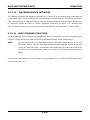
2.3.8
PORTABLE BATS - ANALOG SENSOR INTERFACE
The ANALOG input connector allows input of an analog signal from a compass, dynamic motion
sensing system, (analog pitch and roll signals from an external sensor such as the EdgeTech Model
4414B), and also the depth signal from an underwater vehicle. For the Analog Input connections
see Figure 2-23. An interface cable is provided, see Figure 2-24, 4450BA0166, for inputting analog
pitch and roll sensors to the BATS. The 4760B MRU uses this interface to provide +12VDC to the
unit while the RS232 connects to COM #3.
2.3.8.1
DEPTH INPUTS
The analog output voltage from a depth sensor (typically located on a vehicle being tracked) connects to the ANALOG input connector located on the rear panel of the Transceiver. See Figure 2-19.
The BATS converts this analog voltage (0 - 6 VDC maximum) to a target depth.
2.3.8.2
ANALOG COMPASS INPUT
The analog output voltage from a compass (0 - 6 VDC maximum) connects to the COMPASS input
of the ANALOG connector. See Figure 2-23. The BATS converts this analog voltage to a vessel
heading in degrees.
3
NOTE:
The REMOTE-IN trigger is optically coupled.
2-42
BATS AND PORTABLE BATS
INSTALLATION
BATS-PORTABLE ANALOG CONNECTOR
FIGURE 2-23
2-43
BATS AND PORTABLE BATS
INSTALLATION
BATS-PORTABLE ANALOG CONNECTOR
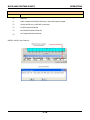
FIGURE 2-24
2-44
BATS AND PORTABLE BATS
2.3.8.3
INSTALLATION
VRU INTERFACE (MODEL 4414B)
The VRU input of the ANALOG connector accepts PITCH and ROLL analog signals from an external
dynamic motion sensing system, such as the EdgeTech Model 4414B. (See Figure 2-24.) The pitch
and roll signals compensate target position for vessel motion. The analog inputs can accept voltages up to +/-10 VDC. The normal vessel motion for a positive Voltage pitch is BOW UP and the normal vessel motion for a positive Voltage roll is PORT UP. The polarity of the analog input signals to
the Transceiver can be reversed and compensated for in the REMOTE VRU POLARITY menu. Normal
polarity for pitching bow up is (+) and for rolling port side up is (+). The VRU scaling can also be
modified under the REMOTE VRU SCALE menu. Normal scaling LINEAR is 0.2 V/degree (+/- 10VDC
= +/-50°). (optional scaling is 10 sin )
NOTE:
For a Remote VRU the normal voltage polarity for pitching BOW UP is [+]. The normal voltage polarity for rolling PORT UP is [+]. The system configuration software
(Trackman) shows the roll and pitch polarity [+] when the vessel pitches BOW UP or
rolls PORT UP. The RS232 Format STD W/PR (standard format with pitch and roll at
end of data string) also outputs data with this same protocol. The RS232 Format
NMEA ORE (NMEA 0183 type format string that is proprietary to EdgeTech and includes pitch and roll data at end of string) is different in that it outputs data in the
same polarity as its incoming voltage. This allows pass-through of signals from remote VRU to integrated navigation system without modification of polarities.
When using the Model 4730B VRU setup the Attitude Sensor for Internal. This automatically sets up the parameters to agree with this standard EdgeTech sensor.
Connect the pitch signal to pin-L and the roll signal to pin-S. Connect the analog commons to pinsP & R respectively.
Also see the newer EdgeTech MODEL 4760B MRU. It uses MEMS technology to provide very accurate pitch and roll data. It connects to the Analog Connector for its power and to COM#3 for its
data.
2-45
BATS AND PORTABLE BATS
2.4
INSTALLATION
HYDROPHONE OFFSETS
The BATS computes range and bearing relative to the hydrophone, unless the system is instructed
to add or subtract corrections (offsets) which relate range and bearing to some other reference
point on the vessel. The hydrophone centerline, or zero bearing, is indicated by the index mark
(see Figure 2-1, 2-2 & 2-3), and is generally aligned so that it corresponds to the vessel heading.
It is difficult and time consuming to fabricate a mounting in which the hydrophone heading is
aligned to within a degree of the vessel centerline, unless the vessel is in drydock. If you have the
facilities to perform an exact mechanical alignment, or if the installation is to be permanent, consider fabricating a mount that repeatedly returns the hydrophone to the same physical location
aligned to within 0.5 degrees of the vessel centerline.
Most operations requiring a portable tracking system will be on various vessels of opportunity, and
require a quick and temporary mounting. In this case align the hydrophone with the vessel centerline as closely as possible. Use some variation of the following procedure to determine hydrophone
offsets.
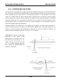
2.4.1 BEARING OFFSET
The bearing offset must be determined before X, Y and Z offsets can be measured.
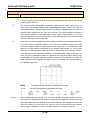
1.
Measure the distance (d) from the vessel centerline to the hydrophone location as shown in
Figure 2-25.
NOTE:
Almost all vessels have a centerline weld or plank that runs down the deck that can
be used for alignment purposes. If your vessel has a seamless deck, you have to
measure the vessel beam and determine the true centerline.
2.
Weight a line to suspend the acoustic tracking source vertically in the water.
3.
As far forward on the vessel as possible, hang the weighted acoustic beacon over the side at
the same distance from the vessel centerline as the hydrophone. (position B1 in Figure 225.) It may be necessary to use a length of pipe or a boathook to extend the weighted line
the required distance. The beacon should be slightly deeper than the hydrophone.
4.
Turn the System on and set it up to track the beacon in use. If you have aligned the mounting bracket correctly, the system tracks the beacon at or very near a 0.0-degree bearing.
5.
If you have designed a mounting that can rotate while in the vertical position, you can rotate the hydrophone until you obtain the correct reading. If you cannot rotate the pipe it will
be necessary to enter a bearing correction at the time of operation. Bearing Offset can be
entered under the USBL HYDROPHONE PARAMETER menu.
2-46
BATS AND PORTABLE BATS
INSTALLATION
The bearing value is the number of degrees that you need to add or subtract to the displayed target bearing to bring it to 0.0 degrees.
For example, a minus 5 degrees would
subtract 5 degrees from the target (beacon) bearing while a positive 5 degrees would add to
the present target bearing. See Figure 2-26.
6.
To check the bearing value determined in step 5, take the weighted beacon line to the stern
of the vessel and again hang it straight down at the same distance from the vessel centerline as the hydrophone (position B2 in Figure 2-25).
The target bearing should now be 180 degrees on the Trackman display.
7.
A further cross check can be performed by taking the weighted beacon to a position directly
across the vessel from the hydrophone (position B3 in Figure 2-25). The target bearing display should now read either 090 or 270 degrees, depending on which side of the vessel the
mounting is located.
2-47
BATS AND PORTABLE BATS
INSTALLATION
FIGURE 2-25
2-48
BATS AND PORTABLE BATS
INSTALLATION
HYDROPHO
NE
BOW ALIGNM
ENT
HYD 0 deg ref
BEACON
LOCATION #1
d1
5.0°
Hydrophone is mounted with a 5 degrees
positive bearing offset. Target (beacon)
bearing on Trackpoint reads 355 degrees
at location #1 and 175 degrees at location
#2. To correct for this enter a positive 5
degrees Bearing Offset under the USBL
Hydrophone Parameters menu in the
Trackman Software.
HYDROPHONE
d1 = d2
BEACON
LOCATION #2
d2
HYD 180
deg ref
FIGURE 2-26
2-49
BATS AND PORTABLE BATS
INSTALLATION
2.4.2 HYDROPHONE X AND Y OFFSETS AND HYDROPHONE DEPTH
Hydrophone Offsets are used to reference the target position to the pitch / roll center of the vessel
and also to correct for the hydrophones dynamic motion. Hydrophone motion is due to the pitching
and rolling of the vessel when it is not on the pitch or roll center of the vessel. ( It is assumed the
hydrophone is rigidly mounted to the vessel. ) The hydrophone, when mounted offset from the
vessel’s pitch / roll center, swings in an arc about the pitch / roll center causing variations in the
hydrophone depth, X and Y offsets as the vessel experiences dynamic motion. These variations
cause the target to appear at a different depth, depression angle and bearing than it actually is.
By entering in X, Y and Z offsets the system can correct for this dynamic motion if a survey grade
Motion Sensing System is interfaced to the BATS. See EdgeTech Model 4414B Motion Sensing System. Connect the analog outputs from the Motion Sensor to the rear panel Gyro/VRU input connector.
Hydrophone X and Y offsets are entered with respect to the pitch / roll center of the vessel. ( It is
assumed that the vertical reference for the pitch / roll center is the water-line of the vessel or the
entered “DEPTH OFFSET”. )
NOTE:
The Trackman Software outputs the target position (X & Y) with respect to the pitch
/ roll center of the vessel graphically in the Display, numerically in the Status Block
and also on the RS-232 serial communications port.
In Figure 2-26, horizontal distance and bearing (X & Y) for the beacon are determined relative to
the pitch / roll center of the vessel (C). (Note that the slant range remains relative to the Hydrophone.) Determine the Hydrophone X and Y offsets as follows:
A.
Measure the distance between the hydrophone (H) and the pitch / roll center of the vessel
(C) in terms of X and Y coordinates on a horizontal plane at water level.
The X coordinate is the distance perpendicular to the centerline (dx H in Figure 2-27). The Y
coordinate is the distance parallel to or along the centerline (dyH in Figure 2-27).
Distance along the X-axis from the centerline towards a starboard direction has a positive
value. In this example, the X offset is 7 meters. Distance towards the port side of the vessel has a negative value.
The hydrophone's distance along the Y-axis, forward of the pitch / roll center, is a positive
value. In Figure 2-27, the hydrophone is aft of the pitch / roll center, and the Y offset is -10
meters.
B.
Enter the offsets at the Trackman and observe the display to verify that the hydrophone is
being offset in the proper directions. Figure 2-27 illustrates the tracking window display as
the X and Y offsets determined above are entered.
2-50
BATS AND PORTABLE BATS
INSTALLATION
The hydrophone is represented in the tracking window by a small H. Note that the H shifts
to the right along the X-axis when the positive X offset (7 meters) is entered. The H moves
down, parallel to the Y-axis, when the negative Y offset (-10 meters) is entered.
The target continues to be tracked and now displays X and Y data in relation to the pitch /
roll center of the vessel.
C.
Hydrophone Depth is the depth of the hydrophone below the surface of the water. (Refer to
Figure 2-27.) Depth is entered as a positive value.
The BATS is ready for operation when the hydrophone is in position and the necessary offsets have
been determined, and the acoustic sources to be tracked are active and in the water.
NOTE:
If a pinger is at a depression angle of less than 20 degrees, the measured depression
angle and, therefore, the horizontal range of the beacon are impossible to measure
accurately. Consequently, the bearing of the source, relative to some offset position,
is impossible to determine. If this combination of circumstances occurs (pinger; depression angle less than 20 degrees; and hydrophone offsets entered), BATS ignores
the entered X and Y offsets so that it can display a correct bearing relative to the hydrophone. Refer to section 3.6, error code 51.
2-51
BATS AND PORTABLE BATS
INSTALLATION
FIG-
URE
227
2-52
BATS AND PORTABLE BATS
INSTALLATION
2.4.3 HYDROPHONE-VRU OFFSET
The VRU offset is the difference in angle between the installed hydrophone and vertical (static offset). (It can also represent the offset between the Remote Dynamic Motion Sensor and the Hydrophone.) Offsets can occur either due to a mis-aligned hydrophone or from changes in trim to the
vessel. The system allows for either manual entry of attitude error corrections or auto correction
via the hydrophone's internal VRU for offsetting the static tilt of the hydrophone/staff. The attitude
(pitch/roll) offsets are error constants that subtract from the remote or external dynamic motion
sensing system data to compensate for the non-vertical installation of the Hydrophone shaft (or
difference between DMS and Hydrophone).
ENTERED OFFSETS: For manual entry the operator must measure the angle of the shaft with respect to vertical and enter the data in the PITCH-ROLL ERROR menu. The vessel should be in a
harbor or at dock to perform this measurement. Pitch and roll errors are entered in degrees. The
system accepts and displays data with a precision of 0.01 degrees.
ORIENTATION: Change the VRU ORIENTATION
if
the
Model
4740A
VRU/Amplifier is mounted on a surface other than bow facing. For example, if the arrow at the top of the
unit is pointing towards starboard
then change the ORIENTATION parameter to starboard.
2-53
BATS AND PORTABLE BATS
INSTALLATION
ENTERING X AND Y OFFSETS
TRACKING WINDOW
GRID SPACING 25yd
Y
X
X OFFSET = 0yd
Y OFFSET = 0yd
X
X OFFSET = 7yd
Y OFFSET = 0yd
X
X OFFSET = 7yd
Y OFFSET = -10yd
STD. DISPLAY, NO OFFSETS
Y
H
X OFFSET ENTERED
Y
Figure 2-10
H
Y OFFSET ENTERED
= REFERENCE POINT
= BEACON
H = HYDROPHONE
FIGURE 2-28
2-54
BATS AND PORTABLE BATS
2.5
INSTALLATION
SOFTWARE INSTALLATION
The BATS control and display software, “Trackman”, is provided on a cd. The minimum hardware
requirements are…
Operating System
Win-2000 or XP (XP recommended)
Hardware Platform
A PC with Pentium-3 or better processor, SVGA graphics (the
software will run on 640 x 480 VGA, but this is not
recommended) and at least 512 Megabytes of RAM is required
as a minimum or 1GByte recommended for optimal
performance of the TRACKMAN software. An Ethernet Port. A
CD ROM drive in order to install the software.
2.5.1 INSTALLATION FROM CD
Boot up pc and insert the “Trackman” cd into cd-rom drive.
The “TRACKMAN” CD contains the following files for installation.
2-55
BATS AND PORTABLE BATS
INSTALLATION
_SETUP.1
_SETUP.DLL
_INST32I.EX_
_ISDEL.EXE
SETUP.EXE
DISK1.ID
AUTORUN.INF
SETUP.INI
SETUP.INS
SETUP.ISS
_SETUP.LIB
SETUP.PKG
As long as the CD drive recognizes the “autorun.inf” file the installation program begins automatically. If not, then
from the “RUN” line in Windows, type in the drive letter of the CD ROM drive and the file name “setup.exe”. E.g.,
E: setup.exe.
Once the installation program has started you will see the following dialog boxes.
Welcome screen with note on exiting all programs prior to installation.
2-56
BATS AND PORTABLE BATS
INSTALLATION
Readme information on the Packer used to compress the files.
Hit Next button to continue.
Destination of the files to be installed. You can
either use the default folder of C:\PROGRAM
FILES\ORE OFFSHORE\ TRACKPOINT MMI or the folder
of your choice. Hit Browse button to select different folder.
(Note: MMI = Man Machine Interface)
Hit Next Button to continue.
The name for the Program Folder that the
Trackman application will be installed under is
shown
next.
The
Default
Folder
name
is
TRACKPOINT MMI. Type in a new folder name under the Program Folders: edit box to change the
Program Folder name. (The default name is recommended for ease of upgrading in future.)
HIT NEXT BUTTON TO CONTINUE.
2-57
BATS AND PORTABLE BATS
INSTALLATION
The installation program displays the Target Folder path that it will create and install program into. If these settings are OK
then hit the Next button to continue.
Once installation begins you still have the
option to cancel the install prior to it finishing. Click the Cancel button to stop the install. You then have the option of Resuming
the install or Exiting the install program.
The installation program creates a TrackPoint
MMI item under the Programs menu.
2.5.2 CALIBRATION FILES
Copy the CAL Files located on the CD to the Trackman PC (Laptop) or Model 4451A under the following directory;
c:\Program Files\ORE Offshore\Trackpoint MMI\CalFiles\InUseCAL\*.bhi
c:\Program Files\ORE Offshore\Trackpoint MMI\CalFiles\InUseCAL\*.blo
2-58
SECTION THREE
OPERATION
BATS AND PORTABLE BATS
3.
OPERATION
OPERATION
Once Trackman software is installed (if PC not supplied) and all cables are connected as per section
2;
Open up display panel and keyboard. Turn on Display/Keyboard from rear of unit.
Turn on Transceiver from front of unit.
Turn on Processor from rear of unit and then open up front panel access with key. Press momentary switch at left. See Figure 3-1.
MODEL 4451A “ON” SWITCH
FIGURE 3-1
The Windows® operating system boots-up and starts the EdgeTech BATS Interface (TRACKMAN)
program. The Trackman program automatically sends the previously setup system and target parameters to the Transceiver upon start-up4. The Transceiver returns the status of the system and it
is displayed on the screen. (Also, see “Get BATS Config” under SETUP menu). In a rack mount configuration supplied by EdgeTech, if the power is removed from the unit, the PC automatically starts
and boots into the TRACKMAN program without operator intervention upon return of power.
4
It takes approximately 35 seconds for the Transceiver to boot-up. Wait at least 30 seconds after
booting the PC before setting parameters within TRACKMAN.
3-1
BATS AND PORTABLE BATS
OPERATION
NOTE: The Hydrophone calibration data is used by the Trackman software. A set of calibration files
(included with every Hydrophone) is copied into its directory. Changing of the Hydrophone requires
that the two files that comprise the calibration factors be installed into the Trackman PC’s folder;
C:\Program Files\ORE Offshore\Trackpoint MMI\CalFiles\InUseCAL\.
The BATS Transceiver, Model 4460C, front panel is shown in Figure 3-2. The front panel contains
an ON/OFF switch and LED indicators for troubleshooting system. (The indicators are the same for
the Portable BATS Model 4461A.) The LED indicators are described as follows…
POWER
+5
When illuminated, indicates that the +5V supply is operational.
+12
When illuminated, indicates that the +12V supply is operational.
-12
When illuminated, indicates that the -12V supply is operational.
+24
When illuminated, indicates that the +24V supply is operational.
SELF TEST
When illuminated, indicates when performing its internal self test function.
TARGETS
TRIG IN (1,2,3,4)
When illuminated (yellow), indicates that a trigger has been received from an
external source.
INTERR (1,2,3,4)
When illuminated (green), indicates when a beacon has been interrogated,
either Internally or Externally (1, 2, 3 or 4
RECEIVE (1,2,3,4)
When illuminated (red), indicates when a beacon reply has been received
from the indicated Target Acquisition Module (1, 2, 3 or 4).
5
COM PORTS
XMT (1,2,3)
When illuminated (yellow), indicates that the Transceiver has Transmitted data from its COM PORT #1, 2 or 3.
RCV (1,2,3)
When illuminated (green), indicates that the Transceiver has Received data
into its COM PORT #1, 2 or 3.
1PPS GPS
When illuminated (yellow), indicates that the Transceiver has received the 1
PPS signal from a GPS timing sync module.
5
The LED indication will be approximately 1 interrogation cycle behind in time as all processing
/detection takes place at the end of the cycle.
3-2
BATS AND PORTABLE BATS
OPERATION
DSP
RX1
When illuminated (green), indicates that the internal data acquisition DSP
card is receiving data from the internal SBC (Single Board Computer) . It illuminates when the Trackman software sends a system parameter to the
Transceiver.
TX1
When illuminated (yellow), indicates that the internal data acquisition DSP
card is transmitting data to its internal SBC. It illuminates when the the DSP
is sending data to the SBC.
E-NET
When illuminated/flashing indicates activity on the Ethernet lines. If no flashing or continuous illumination then usually indicates a hardware Ethernet connection problem. Some flashing but no
connection usually indicates a software setting, IP address or Port number is wrong.
3-3
BATS AND PORTABLE BATS
OPERATION
MODEL 4460B FRONT PANEL
FIGURE 3-2
3-4
BATS AND PORTABLE BATS
3.1
OPERATION
“TRACKMAN” SOFTWARE PHILOSOPHY
I know from experience that sometimes you can just run a program and everything seems intuitive
from the start. Other programs you struggle through and nothing makes sense as far as the menu
structure. I am going to give a brief overview of our design philosophy and how and why it was developed this way. So, when you are plucking through the menus saying to yourself “What was that
person thinking?” maybe this will help! If not, send us an email. Criticism accepted! This software
has been designed and tested on various computers and operating systems. It can run under Windows® 95, 98, ME, NT, 2000, and XP. Even given all our testing, I am sure there are some combinations of hardware and software that will cause some quirks in its operation, but for the majority
of machines it is stable. See section 2 for recommended hardware and operating systems.
The “Trackman” (originally TrackPoint Data/Control Manager) software evolved from EdgeTech’s
earlier TrackPoint II USBL system. It was designed to allow an interface between any of our new or
future USBL products. It also has a means to communicate with Navigation software (e.g., IPS) on
the same PC using UDP or TCPIP, that is sending the USBL data to a software port and having the
Navigation software read it directly without having to go through hardware ports. This Trackman
program can then be hidden6 (minimized) once the USBL System has been setup and the Navigation software run as the primary display. See SETUP menu. The basic menu structure is shown below.
File Menu
Similar Windows environment FILE pull down menu. Controls typical PC
interface items such as disk services and printer, etc. Exit also.
View Menu
Having to do with the viewing of the screen either plotting or setup.
Setup Menu
This is for system setup not related to the USBL system or BATS Transceiver. Beacons, PC, etc.
USBL Menu
Allows setup of items pertaining to the USBL Transceiver.
Test Menu
Built-in test or simulated target.
Window Menu
Allows various modes of tiling (Tile Custom & Auto Tile Custom) the windows, Tracking, Project, etc.
Help
6
Various Help Topics
There is a feature (“Update While Hidden” function) that allows the Trackman software to not up-
date the plotting while hidden (minimized). This saves a lot of processing power for use in other
programs such as the Integrated Navigation programs. Trackman’s main function is then to just
collect and process data and pass it on to an Integrated Navigation Software package.
3-5
BATS AND PORTABLE BATS
OPERATION
Menu Structure:
File Menu
Create New Job
Open Existing Job
Disk Services
Printer Services
Exit
Creates a new job configuration
Opens an existing job configuration
Open Disk Services dialog
Open Printer Services dialog
Exits the application
View Menu
Display Options
Project
Clear Grid
Clear Status Bar
Open Display Options dialog
Brings the Project Tree into view when not docked
Clear the Plotting Grid
Clear all Status Bar messages
Setup Menu
Beacon Wizard
Beacon List
Devices List (ports)
Data Output
Attitude Sensor Setup
Compass Setup
Reset Devices/Ports
Reset Grid/Graphics
Find BATS
Hints (Tool Tips)
Update While Hidden
Opens the Beacon Wizard dialog
Opens the Beacon List
Open the Device List
Opens to Output section of Device List
Opens up the Pitch/Roll Sensor Setup dialog
Opens the Compass Setup dialog
Shuts down and re-enables all Devices
Clears the graphics in the Grid Area
Trackman Searches for BATS devices on a network
Enable/Disable Tool Tips
When Trackman is hidden (tool bar) shuts down the graphics to
reduce processing overhead and sends only updates out its
communications ports.
USBL Menu
GPS/TimeSync
Hydrophone
Acoustic Data
Send BATS Config
Get Sensor Data
Get Status
Window Menu (All)
Open GPS/TimeSync dialog
Open Hydrophone dialog
Open Acoustic Data dialog
Sends configuration to TrackPoint
Retrieves Sensor Data from TrackPoint III
Obtains the Status of the TrackPoint III Transceiver
Enhanced Windows MDI 'Window' menu
Help Menu
Contents
Error Codes
About
Display Help File contents page
Display Error Code info
Display the About Box
3-6
BATS AND PORTABLE BATS
OPERATION
Other items of interest…
Jobs: Stores all the setup parameters to a “Jobs” folder/file.
Project Tree: A Project Tree was developed as a graphical view of the parameters that normally
would change via the standard menus. It is a drag & drop window that can move or be hidden. The
Computer icon is shown at the top as the primary unit. This is the hardware platform that runs this
software. Under the Computer are it peripherals, display, disk services, printer, etc. The Device List
shows in a table7 all the peripheral ports that communicate with the PC including the USBL System
(BATS). A device can be any peripheral associated with the USBL System. It can communicate via
its serial ports or TCP, UDP or UDP Broadcast. The Data Output icon brings up the same Device table but goes directly to the Device output line within the table. Just click on the line or hit Enter
and the setup dialog box is displayed to allow setup of a port to output the tracking data. (We
could have left this out and just showed the Device List but felt this brings attention to the operator
to make sure the Data Output port is setup for the job.) The “to USBL Interface” is only for graphical representation of a port going to a USBL device (COM port). The “BATS” is only for graphical
representation of the Transceiver. Under the “BATS” are the items associated directly with it. It
shows the typical items that the operator should setup for USBL operation; GPS/TimeSync (format
of data input), Hydrophone parameters, Acoustic Data (Speed of sound in water, temperature,
etc.). The GPS is used for time syncing only. It does not reference the data to Latitude /Longitude.
Typical ZDA or GGA sentence received uses the first character in sentence as the sync pulse for the
time received in the sentence. This sets the clock within the Transceiver to better than 50ms accuracy. The time that is on each beacon’s output sentence is the time that each reply was received.
Sensor Setup: This is a system input setup dialog. Sensor inputs can be either from Heading Sensor (an analog or serial input to the Transceiver or serial only to the PC) or an Attitude Sensor (internal to BATS Hydrophone if applicable or a remote analog sensor input to the Transceiver or
NMEA into either USBL or Trackman PC).
Beacons: Clicking on the Beacon(s) icon brings up a table for beacon entry. It also provides a
quick view of the Beacon parameter settings. Click on any line within the Beacon Setup Table to
bring up its dialog setup box.
ORE ICON: Right clicking on the ORE icon on the task bar brings up a menu to allow closing of
Trackman, showing the About box, or disabling the screen saver. For example, disabling the screen
saver can be useful when tracking your ROV and the screen saver decides to start the starfieldR
display just when you are trying to see where your ROV is with respect to the boats prop! Click on
“Disable Screen Saver” to prevent screen saver from turning on.
Device List Status Blocks:
7
When the table is displayed the “Trackman” GUI is minimized.
3-7
BATS AND PORTABLE BATS
The
communication
function
OPERATION
within
Trackman is an ActiveX module. Internal
to Trackman it is called the “TrakComX”
module (TrakComX.ocx). It is used for
communication
with
various
"devices"
over Serial (COM) Ports or TCP_IP Sockets. Each "device" (BATS, depth sensor,
compass, gyro, GPS, etc.) that Trackman
connects to creates a 'copy' of TrakComX for that "device". (See Technical Note below.) A “Status
Block” for each of the devices is shown in the lower right corner of the screen (Trackman Status
Bar). It shows the Device number along with a simulated “LED” that blinks with the input or output
of data. For example, two of these are shown above, one for “device” 1 and one for “device” 4: The
two small green rectangles on the right side of each window act as transmit and receive indicators
(left is transmit, right is receive) that ‘flash’ to indicate activity. The yellow background behind a
number indicates an error has occurred on that device. Left-clicking on the number brings up the
Error/Data Viewer window which can be used to display a running list of errors of the received data. Putting cursor over the
device
number
shows
a
tool tip for that device giving
device
name,
port
number and baud rate.
Error/Data Viewing Window
3-8
BATS AND PORTABLE BATS
OPERATION
Technical Note:
A software function within Trackman called TrakComX (aka a 'WinPort'), handles both Serial Ports
and Sockets, each WinPort can handle a single Serial Port or Socket. Due to hardware constraints
in Windows, if a Serial Port is already in use by an existing copy of WinPort an attempt to create a
new copy using the same Serial Port will fail. This means that two copies of WinPort can NOT share
a Serial Port!
Unfortunately, since many of the "devices" that we want to connect to are in fact individual pieces
of hardware, they often share a common serial or network "bus" with many different style packets
from the different "devices" running down the same wire. This means that some of the different
"devices" we are trying to connect to may be on the same Serial Port such that if we were to try
and use a separate copy of WinPort for each copy of TrakComX on that Serial Port all but the first
one will fail.
Our way around this is to manage a 'pool' of WinPorts that allow copies of TrakComX, that require
the same Serial Port, to share a copy of WinPort. Each time a TrakComX copy is created, the "pool"
is checked to see if an existing copy of WinPort is already handling the new TrakComX copy's desired Serial Port, and if so, the existing WinPort is 'shared' by the new copy of TrakComX.
3-9
BATS AND PORTABLE BATS
3.2
OPERATION
“TRACKMAN” MAIN WINDOW
Application Overview
The TrackMan Windows application provides a user-friendly interface for managing the EdgeTech
BATS or BATS Portable USBL (Ultra Short Base Line) underwater navigation systems.
The interface to the BATS is via the Ethernet port. Other peripherals (Compass, Motion, or Depth
Sensors) may connect via a COM (serial) port connection or a TCP/IP socket. This interface is handled by the TrakComX ActiveX control internal to Trackman.
From the application, the user can enter parameters by clicking on items displayed on a convenient
tree diagram (the Project Tree) on the left side of the main screen. Data is displayed in one or
more MDI child windows, such as the Plotting Grid, on the right side of the main screen.
If the application is being used only as an interface between BATS and another navigation application, it can be hidden from view via a left-click on the Tray Icon (the ORE icon in the System Tray
area at the right end of the Task Bar). When hidden, a left-click on the Tray Icon will bring it back
into view. Right-clicking the Tray Icon brings up a menu providing the ability to disable the screen
saver, view the About Box, or close the application.
From the PC, start the Trackman application by navigating to the Program Folder [TrackPoint
TRACKMAN] and clicking on the TrackMan application button. The main window is displayed. See
figure below. It shows the Project Tree diagram on the left. The tree provides quick access to various configuration information. Clicking on most items will pop up a dialog window associated with
that item.
Trackman starts running the previous “Job” that was saved. The Trackman software is a Windows
based application that provides a remote interface from a PC to the BATS Transceiver providing
target display and data output.
Project Tree Window
The Project Tree Window provides the user with a tree-oriented view of the system. The tree's
nodes indicate the relationships of the various components. Most of the nodes provide direct access
(via the keyboard or via mouse double-clicks) to related setup dialog windows.
Computer Node - This node displays various sub-nodes (Display Options, Disk Services, etc.) that
provide access to basic system services as well as sub-nodes for access to the USBL Interface dialogs.
3-10
BATS AND PORTABLE BATS
OPERATION
TRACKMAN BOOT-UP SCREEN
Sensor Setup Node – Displays setup paths for the various input sensors such as Compass and
Pitch/Roll.
Beacon Node - The Beacon node provides access to the Beacon List window (via the 'Beacon(s)'
entry) as well as individual access to the Beacon Setup dialog window for previously defined beacons whose names show as sub-nodes to the Beacon Node.
The Project Tree window can be undocked from the Main Window making the entire client area of
the Main Window available for MDI Child Windows (such as the Plotting Grid). To undock hold down
the right mouse button while over the Project Tree, move the mouse pointer outside the Main Window's boundary, and release the mouse button. To re-dock hold down the right mouse button while
over the Project Tree, move the mouse pointer inside the Main Window's boundary, and release the
button. The undocked ('floating') Project Tree window can be brought into view at any time via the
'Project' entry of the Main Menu's ' View' menu, or via the System Menu's or Tray Menu's 'View
Project' entry.
3-11
BATS AND PORTABLE BATS
OPERATION
Project Tree: Press and Hold right mouse button. Drag
Project Block off to the side. The Block can then be closed
or hidden by changing the Trackfull . It can be viewed again by se-
out by clicking on the
man main screen to
lecting View from main menu and then “Project”. Dragging
Project Block back over grid area using right mouse button
and releasing causes block to re-position itself next to the
grid. The project block menu is a quick way to access many
of the setup parameters required within the USBL system.
The Computer refers to the PC which can have many peripherals (shown as sub-sets) such as; Display, Disks, Printer,
Data Output (Device List) and an interface to configure the
USBL parameters (BATS). The BATS sub-set parameters
consist of heading sensor, Hydrophone and Acoustic Data.
Separate from the Computer and TrackPoint are the Beacons.
Plotting Window: The Plotting
Window shows the vessel symbol, all target positions and also
the Hydrophone position. The
grid Full Scale and Spacing is
settable via the View / Display
Options menu along with vessel
height and width. The Plotting
Window can also be re-sized
within the constraints of the
main window area or minimized
,
or
out to full screen .
expanded
zoomed
3-12
BATS AND PORTABLE BATS
OPERATION
Plot Screen Options:
Right click on Plotting Window
to bring up the Grid Customization dialog box. This allows
entry of the main title of the
grid area, Viewing Style, Font
Size, Grid colors, Styles, etc.
NOTE: Some functions are
not available within the Track
Plot Customization window.
Target Status: This block shows the processed USBL data for each target. This Block can be resized to show any number of targets at one time by right clicking on edge of window and dragging
up or down. The Status Parameters consist of Target Symbol/ Number, Bearing, Horizontal Distance, X, Y, Depth, Warning Code and Quality Factor. If you right click on the Horz Rng header the
field toggles to Slant Range. Right clicking again changes it back to Horz Rng.
3-13
BATS AND PORTABLE BATS
3.3
OPERATION
“TRACKMAN” MAIN & SUB-MENUS
The Trackman main menu Pull-Down Lists are shown above. The sub-menus are displayed once
the main menus are selected with mouse or keypad. When using keypad… press and release the
Alt key and the main menu is selected with the primary character underlined for each menu. For
example, the File menu has the “F” underlined. Pressing the “F” key selects that menu. View = V,
etc.
3.3.1 FILE MENU
File Create New Job Folder
The Job entry dialog window is used
to define a new job or to access
and/or modify an existing job. Each
job has it’s own complete set parameter files saved in a separate subfolder.
As a ‘Job Name’ is typed in, the ‘Job
Description’ entry and the ‘Job Folder’
entry automatically update with the
‘Job Folder’ using the ‘Job Name’ as it’s sub-folder name. A more complete Job Description can be
typed in if desired.
To select an existing job, simply browse to it’s folder in the folder tree at the bottom of the dialog
and hit the OK button.
3-14
BATS AND PORTABLE BATS
OPERATION
File Open Existing Job Folder
The Job entry dialog window is used
to define a new job or to access
and/or modify an existing job. Each
job has it’s own complete set of parameter files saved in a separate subfolder.
Select a job from the ‘Job Name’ pull
down menu. The ‘Job Description’ is
then displayed for that job. Select OK
to set the system up using those previously set parameters.
The ‘Job Description’ of the active job appears in the Title Bar of Trackman’s Main Window. See below.
File Disk Services
Disk Services requires that at least one Device is selected. For example, when Devices
is selected, a BATS device must have a connection
type
other
than
‘none’
selected.
(Playback, COM port or IP(net)). The Disk
Services dialog controls the ‘Record and Play’
operations for saving and playing back an
EdgeTech specific data files. If a device is active it shows up in the pull-down menu at
right. If no devices are active then a Dialog
box as shown below is displayed. The system
then prompts for display of the Device List,
allowing operator to enable various I/O devices/RS232 port data. Once enabled the devices are shown in the pull-down menu at the
right. See Setup/Device List (ports) for setup
of ports. Only one device can be enabled for
saving to disk.
Click on “Open File” and the standard Windows® dialog box pops up. Enter in File name and click “Open”. The data present on that port will
3-15
BATS AND PORTABLE BATS
OPERATION
now be saved to disk once the RECORD button is pressed. (Save Optional Data will be a future
item.) At any time the saving to disk can be paused by clicking on the “Pause” button. “Resume”
re-starts logging to disk again. The file is saved with a “.ore” extension. It is saved in the same
directory that the “Job” was created under. To Playback target position, go into the DEVICE LIST
and set the TrackPoint device to PLAYBACK mode. Go back into the DISK SERVICES and click on
“Open File” under the Playback Beacon Data and select file. Click Open and then set Playback Rate.
The data will be read at that rate and displayed in the grid.
File Printer Services
This dialog is used to select and set up a printer as
well as to choose what information is to be printed. It
calls the standard Windows Printer Selection and Setup dialogs.
3-16
BATS AND PORTABLE BATS
OPERATION
3.3.2 VIEW MENU
View Display Options
The Display Options dialog is used to
control the Plotting Grid parameters.
This dialog pops-up to the left of the
Grid (if possible) such that the user can
see the changes as they are being
made.
Grid/Auto Scale: Select “Auto Scale”
to have the system automatically adjust to changes in the Full Scale Spacing. The scale is dependent on the Horizontal Distance to the farthest target.
While in Auto Scale mode, the Full
Scale Spacing value is updated such
that the user can ‘freeze’ its value by
shutting Auto Scale off when the Spacing looks right.
Grid/Style: Select the Grid Style either Relative X-Y Rectangular or Relative X-Y Polar.
Grid/Units: Select from the pull-down
menu the units that you want the scale
to be referenced to; either meters,
feet, yards or fathoms.
3-17
BATS AND PORTABLE BATS
OPERATION
Grid/Scaling, Spacing & Zoom: To manually select the Grid and Full Scale Spacing use the scroll
bar arrows next to each of the parameters. To move the bar/value quickly point to the bar with the
mouse, then click and hold the left mouse button down while ‘dragging” bar right or left. Use the
“fine” adjustment buttons as a vernier. Use the Zoom buttons to change the Full Scale and Grid
Spacing values by 2 or 1/2.
Grid/Offsets: The X-Offset parameter moves the grid center position to the right or left and the
Y-Offset parameter moves the grid center position up or down. This is useful when tracking a target in only one quadrant of the vessel. Click on the buttons to change the percentage of movement about the center of the grid.
Grid/Vessel Dimensions: The outline of a ship/boat can be displayed in the center of the grid using the Vessel Dimension settings. Move the scroll bar or click the buttons to vary the Length
and Width values. Select from the pull-down menu the units that
the vessel is to be referenced to; either meters, feet or yards. Select the vessel symbol line color using the color button.
View Project
Brings up the Project Tree (if hidden).
View Clear Grid
Clears the target trails in the Plotting Window.
View Clear Status Bar
Clears Status Bar at bottom of page.
3-18
BATS AND PORTABLE BATS
OPERATION
3.3.3 SETUP MENU
Setup Beacon List
The Beacon List window displays all beacons at once, in a table layout, showing their parameters of
primary interest. (Clicking on the Beacon’s icon within the Project Tree is a quick key to displaying
the Beacon List.
) Having a single window that allows the user to see the
operating frequencies and parameters of all the available beacons makes it possible to compare
parameters and change any that may conflict. Double-clicking on an entry in the list (or using the
arrows keys to move to the desired entry and hitting 'Enter') displays up the Beacon Setup dialog
for that entry. If the entry in the list was 'empty', the Setup dialog comes up in 'Adding a New
Beacon' mode. Entries may be moved to a new position in the list (thereby obtaining a new beacon
number) by cut-and-paste (Ctrl-X / Ctrl-V) keyboard operations. Cut-and-paste operation only
available within beacons 1-4 or within beacons 5-7. (Cannot copy simultaneous to consecutive
tracked beacons or vice versa.) Refer to Section 3.4 for Beacon List examples.
The 4460B can have up to 4 programmed beacons. All four can be active at any one time.
3-19
BATS AND PORTABLE BATS
OPERATION
Adding a new beacon, Dialog Box
Setup Tab
Name: This is the operators
name for the beacon being
tracked, e.g. Towfish.
(NOTE: Cannot have two beacons with same name.)
Serial Number: Serial Number of the beacon as a record
of use.
Symbol: Scroll bar allows selection of a symbol to represent the beacon in use.
Beacon Status: Selects either
Active, Disabled or Fixed Target. For a fixed target to be
displayed in the grid also enter
in bearing and horizontal distance of the target. Enter in the position with respect to the center of
the vessel (assumed pitch/roll center also).
Trail: The target positions are plotted and a line drawn from point to point. Select the color of the
“trail”, the line type and the number of points to store. To clear the trail click on the “Clear Trail”
button. To have no trail then set to one.
3-20
BATS AND PORTABLE BATS
OPERATION
Acoustic Parameters Tab
Type: Selects target type, either
Transponder
Transponder
(acoustic),
(Hardwired),
Re-
sponder or Pinger. If the Transponder or Responder has TimeDecode Telemetry then click on
the Telemetry box.
If a Pinger
is not received an error code #6
is displayed after 12 seconds.
NOTE: When a target is designated as a Pinger it is the only
target that can be enabled at
one time. Disable any other targets.
A Transponder is an underwater
beacon
that
is
interrogated
(Triggered) acoustically. It usually requires a single frequency or tone at a minimum pulse length
before it will respond with its reply frequency. A Turn-Around-Time must be selected in order for
the system to calculate an accurate slant range. A Responder is triggered electrically. For example,
if tracking an ROV or Towfish, utilize the umbilical cable for sending down a key pulse to fire the
unit. This provides a more stable track as you do not have the jitter in range due to the receiver as
in the Transponder. A Pinger requires that the operator know the repetition interval of the beacon.
Select the interval from the pull down list under reply parameters8.
8
When tracking a Pinger the system requires an interrogation interval be entered at the same rate
as the repetition interval. The system automatically sets the interrogation interval from the entered
repetition interval.
3-21
BATS AND PORTABLE BATS
OPERATION
Reply Frequency Setup Parameters: This is the Reply Frequency of the beacon. Select the Reply Type; CW (continuous wave/tone), Shift (linear frequency shifted, also known as chirp or FM),
Coded (special such as Remus codes), M-FSK (multiple- frequency shift keyed; typical for Model
4370A beacons) and PRN (pseudo random number generated codes).
CW (tone)
The CW waveforms are typical of the ORE legacy beacons, Model 4320 or 4330 series (see note below).
The burst is a single frequency with a typical pulse
length of 1.3ms. Select the frequency in 500Hz increments and the correct pulse length9.
SHIFT
The shift waveforms are a linearly changing frequency
over a specific pulse width. Enter in the start frequency and the end frequency in kHz along with the exact
pulse length in ms. For example, an Edgetech Model
4200 Towfish with responder option produces a waveform starting at 24kHz and ending at 28kHz with a
pulse length of 10.000ms.
M-FSK
These waveforms change frequencies in discrete
steps instead of in a linear progression as in the shifted types. The MFSK codes are shown in Appendix E.
CODED
These are proprietary codes of Hydroid’s REMUS underwater vehicles and transponders. They have specific interrogation and reply PRN type codes.
REMUS-1
REMUS-2
REMUS-3
REMUS-4
9
The CW output type beacons such as the Model 4330B as used in the Trackpoint 2 or 3 will not
provide any improvement in performance with BATS. These should only be used in an emergency
not in normal operation.
3-22
BATS AND PORTABLE BATS
OPERATION
PRN
Pseudo Random Number codes. These consist of a single frequency but with 180° phase shifts at
various bits within the sequence. Enter the frequency in kHz (in 1 Hz increments), the PRN code in
octal and chip length in micro-seconds increments (minimum chip length is 100.000 microseconds). The PRN code describes the phase shifting pattern. The chip length is the waveform period
times the number of cycles.
Interrogation Parameters: The Interrogation Parameters consist of the Interrogation Interval,
the Interrogation Frequency and Trigger Source.
Select the Interrogation Interval (based on the slant
range to the target) in seconds and the Pulse Width
necessary to interrogate the beacon in milliseconds.
(In high multi-path environments it may be beneficial to decrease pulse width to prevent multiple
triggering of the transponders.) Select whether the
beacon is being triggered internally by the BATS or
by an external source. If external then select the
edge that the BATS should synchronize the timing
with (+) or (-). If multiple targets are enabled then
a specific Beacon can be set as a “Priority” which
alternates interrogations between all the other active targets.
If two or more targets have the same interrogation
frequency/code then the targets will be tracked
simultaneously. If the Interrogation Frequencies are
different then they will be tracked sequentially.
Trigger Source: Select either Internal or External
trigger source10.
External Key-In Polarity: Select either (+) or (-)
edge external trigger source.
10
Only Target #1 can be set to external trigger mode, becoming the master for all other targets.
3-23
BATS AND PORTABLE BATS
OPERATION
Depth Tab
The Depth Tab configures
the target depth function.
Select the Mode in which the
depth is input from; Telemetry, Analog, Serial Port (PC),
Manual. If the Beacon is a
(time-proportional)
Depth
Telemetry version then select “Telemetry“ and then
under “Depth Mode Setup”
configure the Beacon’s Telemetry parameters. If depth
is via an analog sensor, e.g.,
an ROV or SSS vehicle, then
select “Analog” and then under “Depth Mode Setup” configure the Beacon’s Analog
parameters. The analog port is available at the GYRO connector on the rear panel of the BATS
Desktop or the side panel of the Portable unit. If the target’s depth is available via a serial port,
select “Serial Port” and then under “Depth Mode Setup” configure the Beacon’s Comport parameters. Select the Depth Input sentence, DBS, DBT, PEIV1 or DPT. (See formats below.) This Serial
port is available only at the PC’s serial input not
the Transceiver’s.11
In the TELEMETRY mode the depth is taken from
a depth telemetering transponder. The transponder sends two replies to the Transceiver per
interrogation.
The first reply signal is used to
determine slant range and bearing, while the second reply (whose delay from the first is proportional to depth) is used in the depth calculation.
Given
these
three
parameters
a
three-
dimensional position fix is calculated. The “Telemetry Depth Setup” menu is used in conjunction with “Telemetry Mode”. It contains parameters to allow the operator to change the telemetry
11
If the entered depth is not correct the calculated horizontal range will also be incorrect.
3-24
BATS AND PORTABLE BATS
OPERATION
reply frequency, and also to change the zero delay, full-scale delay and span. When Telemetry
Depth is selected, a 'T' appears next to the depth value in the Status Block when the telemetered
value is being used in the horizontal range calculations. If the system is using a calculated 12 depth
then a `C' appears next to the depth value. If the depth telemetry replies are not received, the last
valid telemetry reply is used for the depth. If telemetry replies return, system reverts back to
depth telemetry. If not using a Telemetry Beacon then depth should be changed to Manual or Analog.
Serial Port Depth Input - DBS, DBT, PEIV1, DPT
DBS - Depth Below Surface
1 2 3 4 5 6 7
| | | | | | |
$--DBS,x.x,f,x.x,M,x.x,F*hh<CR><LF>
Field Number:
1)
Depth, feet (Referenced to Water surface)
2)
f = feet
3)
Depth, meters
4)
M = meters
5)
Depth, Fathoms
6)
F = Fathoms
7)
Checksum
DBT - Depth below transducer
1
|
2
|
3
|
4
|
5
|
6 7
| |
$--DBT,x.x,f,x.x,M,x.x,F*hh<CR><LF>
Field Number:
12
1)
Depth, feet (Referenced to Water surface)
2)
f = feet
3)
Depth, meters
4)
M = meters
5)
Depth, Fathoms
6)
F = Fathoms
7)
Checksum
The System can only calculate depth when the depression angle is greater than 45. (Depres-
sion Angle is defined as 0 at surface and increases to 90 directly below the hydrophone.) When
target is not within this 90 cone below the hydrophone an alternate depth must be used; Analog,
Telemetry or Manual.
3-25
BATS AND PORTABLE BATS
OPERATION
PEIV1 - Depth of Target (EIVA Navipak)
1
|
2
|
3
|
$PEIV1,x.x,yy*hh<CR><LF>
1)
Depth, meters (Referenced to Water surface)
2)
Target Number 01-99
3)
Checksum
DPT - Depth - Deviation & Variation
1
|
3
|
4
|
$--DPT,x.x,x.x*hh<CR><LF>
Field Number:
1)
Depth, meters (Water depth below TP3 Hydrophone)
2)
Offset from transducer, Positive means distance from transducer to water line negative means distance from transducer to keel
3)
Checksum
NOTE: Offsets are not used. The BATS uses Depth to the transducer in its calculations.
Filtering Tab
The “Filtering Tab” allows each
beacon to have individual filtering parameters, configuring
each beacon for its own tracking scenario. Select Filter Level
for the beacon in use. In the
case of a fast moving target
set the level between 1 and 5
with 1 being for minimal filtering and 5 being for moderate
filtering. For slower moving
targets set level between 6
and 10 with the filtering parameters increasing to maximum at 10. To set limits on
known target locations modify
the Slant Range and Bearing
parameters.
When OK is selected the Trackman program sends the parameters to the Transceiver. This delay
causes the dialog box to remain on screen for a few seconds following the command.
3-26
BATS AND PORTABLE BATS
OPERATION
FILTERING provides operator a choice of various combinations of averaging, filtering, threshold
settings and also limits on certain parameters. Filtering includes averaging, target velocity checking, range gating, signal threshold, minimum xponder range, maximum xponder range and signal
rejection via signal quality checking. The filtering parameters are individual per target.
Filter Level: The Filter Level setting is variable from 1 to 10. A Filter Level setting of 1-5 is recommended for most dynamic applications (e.g., ROV tracking).
The higher settings of 6-10 are
appropriate for static applications such as station keeping. The parameter settings for the range
blanking gate and velocity filter “tighten up” as the Filter Level is increased with the premise that
dynamic targets such as AUV’s can change position quickly with respect to the vessel while static
targets such as a tow fish or other moored targets do not. Filter settings 6-10 cause the analog or
telemetry depth to average the last three readings. Filter settings 1-5 do not average the input
depth. Also see error code #5.
The table below shows the relationship between the range gate, velocity filter and averaging
weight Vs the Filter Level setting.
FILTER LEVEL/RANGE (blanking) GATE (Transponders & Responders Only)
If there is more than one sequential target the range blanking gate value is multiplied by the number of targets (e.g., filter level 2 with 4 targets enabled equates to a blanking gate of 80 meters
before the average target range). If the blanking gate exceeds the current range average then it is
set to a minimum (1m). The range average for each target is weighted based on the number of
good replies for that target. If there are no recorded good replies then the routine uses 100%
weight on the current value and is scaled down for up to 4 replies (e.g., if there have been 4 or
more consecutive good replies each new reply contributes 25% to the average). As replies are
missed, more weight gets added to the new reply. If there are more than 2 missed replies, the
blanking gate opens up by a factor of 2, until we exceed a maximum (currently 4) where it is wide
open.
TARGET FILTERING FUNCTION
Filter
Blanking Gate opens prior to av-
Velocity Filtering
Average Weighting
(4.5 m/s = 10 knots;
2.3 m/s = 5 knots)
Ratio of the weight of the
previous reply to the 10th
reply Vs Filter Level 3
erage reply (meters)
Level
1
(based on 1500m/s speed of sound)
-25 meters (-16 ms) x # Active targets
1
OFF
4.0:1
2
-20 meters x # Active targets
1
OFF
3.3:1
3
-15 meters x # Active targets 1
OFF
2.8:1
4
-10 meters x # Active targets
5
-5 meters x # Active targets
1
1
3-27
4.5 m/s + X % SR
2
2.5:1
4.5 m/s + X % SR
2
2.3:1
BATS AND PORTABLE BATS
OPERATION
-25 meters x # Active targets
4
-20 meters x # Active targets
4
8
-15 meters x # Active targets
4
9
-10 meters x # Active targets
4
10
-5 meters (-3.3 ms) x # Active targets
6
7
NOTE 1:
4
4.5 m/s + X % SR
2
2.1:1
2.3 m/s + X % SR
2
2.0:1
2.3 m/s + X % SR
2
1.9:1
2.3 m/s + X % SR
2
1.8:1
2.3 m/s + X % SR
2
1.8:1
For Range Gate description see Transponders and Responder below. Pingers utilize a Time Gating
system, see Pingers below.
NOTE 2:
Total velocity = Target Velocity plus 5% (X) of the Slant Range if external compass is used; Plus 10%
of Slant Range if not used. Used for both Xponders and Pingers.
NOTE 3:
At the higher filter levels the averaging is almost linear across all replies (up to 1.8:1 depending on
number of replies smoothed) while at the lower filter levels the weight is higher on the most recent
reply (up to 4.0:1 depending on number of replies smoothed). The QF also contributes to the weight
in the smoothing buffer. See chart and also QF FILTERING below.
NOTE 4:
Settings 6-10 affect the auto-depth readings (analog or telemetry) by averaging the last three readings. Settings 1-5 do not affect these depth inputs.
Weight on the Target’s Position Vs the Quality Factor as used in the smoothing
QF
1
2
3
4
5
6
7
8
9
10
Weight
0
0
.04
.08
.12
.16
.2
.4
.6
1
RANGE GATE AND TELEMETRY (Transponders & Responders Only)
When telemetry is enabled the system also blank-gates on the telemetry reply. On the primary or
navigation reply the Transceiver accepts only the first signal arriving at the hydrophone following
the opening of the blanking gate and ignores signals for 80 milliseconds following it. When the
telemetry gate opens the Transceiver accepts the first signal at the telemetry frequency and all
other signals are ignored until after the next interrogation. This is advantageous when operating in
a high multi-path environment, insuring that the system locks on to the correct reply.
FILTER LEVEL/TIME GATE (Pingers Only)
For pingers the system uses a Time Gating system based on the targets entered repetition interval
instead of the slant range as used in the range gating. Time gating eliminates any unwanted signal
detections that occur at a time when no response is expected. Since the pinger repetition rate is
entered and the reply interval is known, Transceiver can determine, within some short time interval, when the next signal is expected and only allows signals which fall within their time window to
be accepted for further processing. It depends upon accurate entry of repetition rates in the TARGET sub-menu for proper tracking. The time gate is a function that compares the time between re-
3-28
BATS AND PORTABLE BATS
OPERATION
plies against the entered repetition value. It accepts the first reply that arrives in a window 50 ms
prior to the expected arrival of the signal (beginning of time window) and up to 50 ms after the expected arrival. It then ignores replies later than 50 ms after the calculated time gate window. If no
replies are detected within a certain period, an error code #2 is flagged and the window opens up
to find the reply.
FILTER LEVEL/VELOCITY FILTER
Velocity filtering is a technique of rejecting any target position changes that are unlikely due to an
assumed maximum target velocity and elapsed time since last update. It is based on the difference between the previous X and Y position (averaged, if smoothing is enabled) and the present
targets X and Y position. If the present calculated position passes the velocity filter test it is then
sent to the smoothing function. If after a certain period of time there is no reply within the expected area then an error code #5 is flagged and the system opens up to find the reply.
NOTE:
A fast-turning ship can cause the target to appear to be traveling at excessive
speeds and be rejected by the velocity filter, when the compass option is not in use.
SNR Threshold: The threshold setting is normally set to 20dB (default). Raise the threshold if the
system is triggering on noise, usually indicated by erratic slant ranges. Use caution when setting
threshold lower than 20dB. I.e., if you know the approximate position of the target and you want
to get the maximum range then it may be possible to lower threshold in the presence of low noise.
As the threshold level is increased, only stronger signals are accepted, and weak signals, which
could be caused by multi-path or extraneous noise in the water, are ignored. The lowest threshold
setting increases the sensitivity of detection by recognizing smaller signals. In a high-noise environment this can lead to erratic readings. Higher threshold settings decrease the possibility of detecting on noise, but can lead to occasional missed valid signals and also late detections causing
erratic bearings. A lower threshold setting is usually the best choice, but trial will lead to the optimum threshold setting for a given application.
Averaging: The Averaging parameter is variable from 0 (off) to 10. It is independent of the Filter
Level setting in that you can select the buffer size in which to average a number of replies over (110). This setting corresponds to the number of replies that are averaged along with the present
reply. The averaging routine is used in conjunction with the QF (Quality Factor) and the Filter Level. With a high quality factor the target position is weighted heavily both on the present reply and
on the previous replies in the averaging buffer. If the present reply has a high QF and the previous
reply had a low QF then the position with the high QF remains heavily weighted within the averaging buffer. As new replies are received the high QF positions maintain their heavier weight while
the positions with lower QF’s have very little weight. The weights of the target positions are reduced as the newer replies are received. This approach biases the target position towards the better QF and also towards the most recent reply providing a better representation of target position
than by using a mean or average of the target positions. At the higher filter levels (8-10) the aver-
3-29
BATS AND PORTABLE BATS
OPERATION
aging is almost linear across all replies while at the lower filter levels the weight is higher on the
most recent reply. Averaging occurs on the target's position only (X, Y or HD, BRG), not on the
displayed slant range. The slant range displayed in the status block and sent out the RS-232 is the
actual value. Because of this there may be an apparent discrepancy between the displayed position and slant range.
QF Filtering: QF Filtering is a toggle function that turns QF Filtering on or off. The Quality Factor
(QF) is a value (1-10) determined by the system on each reply that is detected. The system uses
the phase or time counts from each of the hydrophone elements to determine the quality of the
signal. If the phase counts are consistent throughout the reply burst the quality factor is very high.
If the phase counts have jitter or are inconsistent then the quality factor is low. The QF FILTERING
function filters the data depending on the Quality Factor of the signal received. It compares the
Quality Factor of the signal received to its previous five (5) average Quality Factors. The QF FILTERING function toggles Quality Factor checking on or off.
This function filters the data depending on the Quality Factor of the signal received. When “QF FILTERING” is “ON” and the Quality factor is less than the average of the last five QF’s the data is not
plotted and causes an error code #4 to be displayed. In this case the error is considered a “fatal”
error (similar to all other error codes under 20) and the reply is not added to the smoothing buffer.
The target position is not updated on the screen and the positional data is not sent out the RS232
port unless the “EC” formats are chosen. If “EC” formats are chosen then a post processing navigation system could be used to determine if the reply was good or bad by searching for a 4 at the EC
location within the data string. When “QF FILTERING” is “OFF” and the Quality factor is less than
the average of the last five QF’s the data is plotted on the screen and sent out the RS232. The data
is tagged with an error code #64 on both the display and RS232. In this case the error is considered a “warning” error (similar to all other error codes greater than 50). The data is still smoothed
but its “weight” within the averaging buffer is decreased. Again, a post processing navigation system could then be used to determine if the reply was good or bad by searching for a 64 at the EC
location within the data string.
Maximum Target Velocity: Select the Maximum Target Velocity (+/-) if using a PRN or Remus
type codes (as they are susceptible to Doppler shift). If the target, for example, is a towfish (which
has very little relative movement between target and Hydrophone) the MTV can be kept at 5 knots
or less. By keeping the MTV below 5 knots the processing load on the Transceiver is minimized.
Target Limits: The Slant Range Limit (Minimum Transponder or Responder Range) function works
in conjunction with the range gating (blanking) system based on the target slant range. The range
(blanking) gate is a hardware lockout that “opens up” and allows signals to be detected from the
hydrophone. The time that the blanking gate opens is based on the Filter Level and the time the
last reply was received. If a condition occurs where the blanking gate end time is less than the
Slant Range Limit’s (from value) then the blanking gate overrides the Slant Range Limit’s (from
value). This in effect locks-out all signals from the hydrophone prior to the end of the blanking
gate. If the system loses tracking due to the Slant Range Limit (from value) being greater than the
3-30
BATS AND PORTABLE BATS
OPERATION
actual slant range from the target the system shows an error code #7 (SR < Min Range). After 5
interrogations without a reply the system opens up the blanking gate and accepts the reply on the
sixth (6th) interrogation (EC #6 may appear briefly prior to reception of signal). If the Slant Range
is less than the Slant Range Limit’s (from value) then the error code #6 is changed to #7. The
Slant Range Limit’s (from value) can vary from 1 to 1000 meters.
NOTE:
If you are operating with a known minimum range, for example with an ROV near the
bottom in 500 meters of water, then the Slant Range Limit’s (from value) could be set
for 450 meters. This would provide an effective "range gate" without the attendant target acquisition and re-acquisition time of the normal range gate. Of course, as you recover the ROV you will have to reset the Slant Range Limit’s (from value) to track the
ROV to the surface.
The Slant Range Limit’s (to value) (Maximum Slant Range) function compares the reply’s slant
range against this value. If the slant range is greater than the entered value the last good reply
remains on the display (target position on the screen doesn’t change) and the status block shows
an error code #14. If the RS232 Format is set to an “EC” format it also outputs the last good position and tags it with an error code #14. The Slant Range Limit’s (to value) can vary from 0 m
which is OFF to 10 to 10000 meters.
The BEARING LIMIT function is a final check after the range gate and velocity filter are satisfied.
The system checks to see whether the target is within the parameters as set by the bearing limits.
This function is only applicable to targets with a depression angle of less than 45. If a target is
outside the set limits then the system displays an error code #15, "BEARING LIMIT EXCEEDED".
The system does not update the target on the screen but the data is sent out the RS232 (when an
“EC” format is selected) with the fatal error #15 attached to the string. The limits are always referenced to the vessel, whether compass mode is ON or OFF. The default values for the bearing limits
are 0 to 0, which disable the function.
3-31
BATS AND PORTABLE BATS
OPERATION
Acoustic Release Tab
The “Acoustic Release Tab” allows Commandable Beacons /
Releases to be commanded directly from within the BATS unit
using the interrogation element
within the Hydrophone to send
the BACS commands and the
“A” channel receive element to
provide the feed-back from the
Commandable Beacon.
1.)
Activate the Target. Navigate to the Acoustic release tab within the Beacon setup dialog.
2.)
Set the Reply frequency to the Beacon’s (Acoustic Release) feed-back or “acknowledgment”
CW tone. Set threshold to med-high. If more *...*...* appear during the reply acknowledgement than should be then raise threshold and conversely if no *...*...* appear then
lower threshold.
3.)
In the Command Editor window type in the beacons “Enable” Command and then click on
the Save Enable Cmd button.
4.)
Continue the same for the “Disable” and the “Release” commands. The commands are now
stored in the Trackman’s ini file.
5.)
To “Enable” the beacon (allows it to respond to an interrogation) click on the Load Enable
button then click on Send BACS Cmd.
The BATS Hydrophone will transmit the “Enable”
code to the Beacon and if successful will return with a series of CW tones. Each tone reception will be displayed as a * character in the Trackman window.
3-32
BATS AND PORTABLE BATS
OPERATION
For the EdgeTech PORT Acoustic Release, the acknowledgment pings for the Acoustic Commands
received are shown in table below;
Command
Frequency
Time between
Number of Pings when
Number of Pings when
Pings (sec)
release is Vertical
release is tilted >45
ENABLE
NOTE 1
2
6
3
DISABLE
NOTE 1
2
NOTE 2
NOTE 2
RELEASE
NOTE 1
2
6
3
NOTE 1: Tone is a CW burst whose frequency is noted on the supplied Configuration Sheet.
NOTE 2: Battery Indication: When a DISABLE command is received at the Acoustic Release the
acknowledgement replies indicate battery condition rather than tilt. The PORT returns 6
pings for a full battery with successively lower energy for 5, 4, & 3 pings. When down to 2
pings the battery is almost drained. If you have an indication of 2 pings then it would be
prudent to release the unit and recover unit to change out the batteries.
Octal codes representing F1 – F4 are shown below. A diagram showing the timing of
an octal code is also shown below.
3-33
BATS AND PORTABLE BATS
OPERATION
Code (Octal)
Frequency Number
Desired Frequency
100 000
F1
17483
177 777
F2
17986
600 000
F3
18519
677 777
F4
19084
Not currently used
F5
19685
3-34
BATS AND PORTABLE BATS
OPERATION
Setup Device List (Ports)
When selected, the Device List dialog box is displayed and the main window minimizes. (This is the
same as double-clicking on the Device List within the Project Box.) When closing the Device List
window, the main window is displayed again.
The Device List shows the list of all peripherals or I/O to the Processor. (FYI: The Device List is
read from a “devices.ini” file stored under the ORE TrackPoint folder within the Program Files folder. These are EdgeTech configured files and should not require modification.)
Device (ports) Setup dialog box: This box allows setup of the various I/O to the Processor.
Double-clicking on an entry in the list (or using the arrows keys to move to the desired entry and
hitting 'Enter') brings up the Device Setup dialog for that entry.
TrackPoint BATS:
Click on the TrackPoint BATS “Device List” line and then
double click to bring up the Setup Dialog Box.
Setup this dialog as listed below. This port is required to
communicate with the BATS Transceiver.
The “Sentence Input to Trackman” is the data format
that is coming from the BATS USBL Transceiver to the
PC. The “Sentence Output from Trackman” is the data format that is sent from the PC (on this same port) to
the BATS Transceiver.
3-35
BATS AND PORTABLE BATS
OPERATION
The setup parameters for the TrackPoint BATS Device are…
Connection Type
IP Network Settings
IP Address
Port Number
Sentence Input to Trackman
Use Checksum
Sentence Output from Trackman
IP (net)
TCP
192.168.3.X (X usually = 9 but check on top
cover of the BATS Transceiver for IP address.)
50001
TP_SPC (TrackPoint Signal Processor Commands)
Yes
TP_SPC (TrackPoint Signal Processor Commands)
Once this connection protocol has been setup perform a “Find BATS” command under the setup
main menu. Trackman will then find any BATS on the network connection. Click on “connect to” to
make connection to the BATS. Under the USBL main menu click on “get Status”. If communications
have been established the “Get Status” box will be shown
Remote Interface:
Not common. The Remote Interface port is typically for an output to a navigation system that also
communicates with Trackman. Setup the Remote Interface device to output the format that is
compatible with the navigation software. The Connection Type can be either “COM Port” or “IP
(net)”.
The Sentence Input to Trackman can either be “NCSS” or SPC. This is the data format that is
coming from the Remote Control Module (another PC) to this PC or laptop. These are not typical
and are only used for special applications. Leave as “----“. For data output only see Data Output
below. The Sentence Output from Trackman is the data format sent from the PC to the Navigation System. The list of formats available are; PORE, POREB, POREG, SNTTM, STANDARD, STANDARD-EC, STD W/PR, STD-EC W/PR, NCSS, NCSS-EC, NUWC, NUWC-EC, REV 4 & REV 4-EC.
3-36
BATS AND PORTABLE BATS
OPERATION
Remote Interface Dialog Box
3-37
BATS AND PORTABLE BATS
OPERATION
Setup Data Output
Data Output Setup is similar to the Remote
Device Setup. A separate COM port can be
configured to only output data (no control input). There is no Sentence Input to Trackman
as in the Remote Interface Setup.
Setup the Data Output dialog to output the format that is compatible with the navigation software.
The Connection Type can be either “COM Port” or
“IP (net)”.
TCP/IP & UDP Protocols
The global network we all know as the Internet
transfers information between computers using a
protocol (a set of rules) known by the acronym
TCP/IP which stands for Transmission Control Protocol/Internet Protocol.
All Internet transfers use IP (Internet Protocol) as the basic underlying method of 'packaging' data
to be transferred.
Above that underlying packaging 'layer' of operation there are two general methods of transferring
data.
The first method, which is the one most of us know from 'surfing the Web', involves making a
point-to-point connection when transferring data. This point-to-point connection uses the TCP
(Transmission Control Protocol) part of TCP/IP. It's a lot like making a phone call, when the other
person answers the phone your connection is acknowledged and you can transfer data back-andforth (talk) point-to-point.
The second method, called a datagram or connection-less interface, is a simple 'pack it up and ship
it out' technique that essentially works like mailing a letter. With a datagram you don't make a
connection with the receiver, you simply send your data and assume that it will get where you're
sending it. In the Internet world a protocol known as UDP (User Datagram Protocol) is used to
transfer data in this way.
One of the advantages of UDP is that you can send data to more than one receiver at a time since
there's no need to establish a point-to-point connection. This technique is known as UDP broadcast
mode. Using UDP broadcast mode an application acts much like a radio station, it broadcasts data
on a specific IP port and anyone who wants to 'listen' to the data 'tunes in' to that port. There's no
3-38
BATS AND PORTABLE BATS
OPERATION
need to make a point-to-point connection so there's no connection to break when a listener stops
listening.
Normally, the Trackman is the “CLIENT” while the software you are connecting to is a “SERVER”. If
the interface software13 requires that Trackman be a SERVER then click on the check box below the
IP Address.
The Sentence Output from Trackman is the data format sent from the PC to the Navigation
System. The list of formats available are; PORE, POREB, POREG, SNTTM, STANDARD, STANDARDEC, STD W/PR, STD-EC W/PR, NCSS, NCSS-EC, NUWC, NUWC-EC, REV 4 & REV 4-EC.
13
Hypack software requires Trackman be set up as a SERVER.
3-39
BATS AND PORTABLE BATS
OPERATION
Setup Attitude Sensor Setup
This is the System Level Attitude Sensor setup. (Same
as clicking on the Attitude Sensor line in the Project
Tree.)
The pitch and roll signals compensate target position
for
vessel
motion. The analog inputs [Trackpoint
(USBL)] can accept voltages up to +/-10 VDC. The
normal vessel motion for a positive (+) Voltage pitch is
BOW UP and the normal vessel motion for a positive
(+) Voltage roll is PORT UP. The polarity of the analog
input signals into the TP3 can be reversed and compensated for in the USBL ATTITUDE SENSOR POLARITY
dialog box. Normal polarity for pitching bow up is (+)
and for rolling port side up is (+). The VRU
scaling can also be modified under the USBL
ATTITUDE SENSOR menu. Normal scaling is
0.2 V/degree (+/- 10VDC = +/-50°). This dialog also allows the selection of the Compass
Sensor Input to be either from Trackman (PC)
or (TrackPoint (USBL)).
NOTE: For a Remote VRU the normal Voltage
polarity for pitching BOW UP is [+]. The normal voltage polarity for rolling PORT UP is [+].
The RS232 Format STD W/PR (standard format with pitch and roll at end of data string)
also outputs data with this same protocol. The
RS232 Format NMEA ORE (NMEA 0183 type
format string that is proprietary to EdgeTech
and includes pitch and roll data at end of
string) is different in that it outputs data in the
same polarity as its incoming voltage. This allows pass-through of signals from remote VRU
to integrated navigation system without modification of polarities.
For the Trackpoint (USBL) “BATS“ there are three types of Attitude Sensors that can be interfaced to the system are; Internal, Analog or Serial.
The INTERNAL selection is not valid with BATS at this time.
3-40
BATS AND PORTABLE BATS
OPERATION
Select ANALOG when using an external sensor with an analog output. The scaling can then be
modified to be compatible with the external sensor. For example, a Model 4414B Pitch/Roll sensor.
Select SERIAL when using a sensor that outputs the data serially. For example, an NMEA format
from an EdgeTech Model 4760B MRU ($POREM output). The various formats available at the
Trackpoint (USBL) COM ports 2 or 3 are…
TSS1
TSS HHRP
PRDID
CDL/MDL
PSXN (Seatex)
POREM
Configure the Port Settings by selecting the COM Port
that the data is input to the BATS device. (COM 2 or
COM3) Next select the Port #, Baud Rate, Parity, Data Bits and Stop Bits. Note that the baud rate is limited to 38400 and the data rate is limited to 12Hz
on these ports for the Model 4460A and 100Hz
and 115.2k for Models 4460B and Model 4460C.
If the data is input via the Trackman PC then
select from the Attitude Sensor Setup box the
Trackman (PC) button. The Attitude Sensor Input
Setup box is displayed. Select COM Port button at
the top and then select the COM Port settings.
Port #, Baud Rate, Parity, Data Bits and Stop Bits.
Next select the format from the Sentence Settings. The various formats available are…
POREM
POREI
TSS1
PRDID
PSXN
The data on these ports can typically be up to
115,200 baud and rates greater than 100Hz.
3-41
BATS AND PORTABLE BATS
OPERATION
Sentence Formats:
POREM – Pitch, Roll and Heading
1
|
2
|
3
|
4
|
5
|
6
|
7 8
| |
$POREM,+xxx.xx,+xxx.xx,+xxx.xx,+xxx.xx,xxx,+xx.xxx*CS<CR><LF>
Field Number:
1)
Pitch (degrees)
2)
Roll (degrees)
3)
Temperature (degrees C)
4)
Heading (degrees)
5)
Error Code
6)
Heave (meters)
7)
“*” end of sentence delimiter
8)
CS = CheckSum
14
TSS1 – Heave, Roll, and Pitch
1 2
| |
| |
3 45
| ||
| ||
6 78
| ||
| ||
9 11
| 01
| ||
1
2
|
:XXAAAASMHHHHQMRRRRSMPPPP<CR><LF>
Field Number:
14
15
1)
Start Character “:”
2)
Horizontal Acceleration
3)
Vertical Acceleration
4)
Space Character
5)
Space if positive, Minus if negative
6)
Heave (centimeters) (N/A) (positive is above datum)
7)
Status Flag
8)
Space if positive, Minus if negative
9)
Roll X 100 degrees
10)
Space Character
11)
Space if positive, Minus if negative
12)
Pitch X 100 degrees
15
2
If using heading also, make sure to check the “Use Heading From Attitude Sensor” box.
Roll and pitch measurements are in degrees in the range –99.99° to +99.99°. Positive roll is
port-side up, starboard down. Positive pitch is bow up, stern down.
3-42
BATS AND PORTABLE BATS
OPERATION
TSS HHRP2 –Heave, Roll, Pitch and Heading
1
|
|
2 34
| ||
| ||
5 67
| ||
| ||
8 91
| |0
| ||
1 1
1 2
| |
:DDDDSMHHHHQMRRRRSMPPPPM<CR><LF>
Field Number:
1)
Start Character “:”
2)
Heading X 100 degrees
3)
Space Character
4)
Space if positive, Minus if negative
5)
Heave (centimeters) (N/A) (positive is above datum)
6)
Status Flag
7)
Space if positive, Minus if negative
8)
Roll X 100 degrees
9)
Space Character
10)
Space if positive, Minus if negative
11)
Pitch X 100 degrees
12)
Heading Status (N/A)
16
17
4
PRDID - Pitch, Roll and Heading
1
|
2
|
3
|
4
|
$PRDID,+xx.xx,+xx.xx,xxx.xx*CS<CR><LF>
Field Number:
1)
Pitch (+ or -)
2)
Roll (+ or -)
3)
Heading
4)
CS = CheckSum
3
18
16
If using heading also, make sure to check the “Use Heading From Attitude Sensor” box.
17
Roll and pitch measurements are in degrees in the range –99.99° to +99.99°. Positive roll is
port-side up, starboard down. Positive pitch is bow up, stern down.
18
The TSS MAHRS and others may not use the Checksum field. Uncheck the “Use Checksum” box
as required.
3-43
BATS AND PORTABLE BATS
OPERATION
PSXN - Pitch, Roll, Heading and Heave
1
|
2
|
3
|
4
|
$PSXN,23,-xx.xx,-xx.xx,xxx.xx,,*CS<CR><LF>
Field Number:
1) Message 23
2) Roll (degrees) (Positive Port Side Up) (N/A)
3) Pitch (degrees) (Positive Bow Up) (N/A)
4) Heading, True (Degrees)
19
5) Heave (meters) (Positive Up) (N/A)
6) CS = CheckSum
19
If using heading also, make sure to check the “Use Heading From Attitude Sensor” box.
3-44
BATS AND PORTABLE BATS
OPERATION
Setup Compass Setup
This is the System Level Heading sensor setup. (Same
as clicking on the Heading Sensor line in the Project
Tree.)
The heading data can be set to off (None), Grid Only,
Data Output Only or Both Data Output and Grid. If for
example, the Navigation System was to correct for
compass heading and not BATS then set the North Reference to Grid only. The RS-232 data would not be corrected for North but the Target position on the grid
would be.
The Compass Correction can either be…
None
Data O/P Only
Grid Only
Both Data O/P & Grid
Enter in the magnetic variation in degrees.
This dialog also allows the selection of the Compass Sensor Input to be either from Trackman
(PC) or Trackpoint (USBL) (BATS Transceiver).
Clicking on the “TrackPoint (USBL)” button brings
up the “USBL Heading Sensor (Compass)” dialog
box. Select None (to turn off) or the interface required, either Analog as input to the BATS Transceiver’s SYNC connector located on the side panel
or the Serial port which accepts NMEA compass
sentences. The Serial input goes into the DB-9
COMMS connector located on the side panel also
of the Portable or rear panel of the Desktop.
When the compass is enabled (either Analog or
Serial,
Trackman
(PC)
or
TrackPoint
(USBL)
Transceiver), the RS-232 target position data is
automatically switched to north referenced. This means that the target data (bearing, X, Y) output
to the RS-232 port is referenced to North instead of the bow of the vessel. The operator can override this by selecting Compass Setup from the main Setup Menu. Click the pull-down menu of the
dialog box and select where the Compass Correction should be applied; None, Data O/P Only,
Grid Only, Both Data O/P & Grid. The “Grid Only” function is used in situations where Trackman
3-45
BATS AND PORTABLE BATS
OPERATION
is interfaced to a navigation system and the navigation system already interfaces to a heading sensor such as a flux gate compass or gyro-compass. In this case, the Trackman’s RS-232 data does
not need to be corrected for North reference. However, Trackman requires a compass input to
compensate for vessel motion within its filtering algorithms. By selecting “Grid Only“ the target data on the Trackman screen remains referenced to North while the RS-232 data is referenced to the
bow of the vessel thus allowing both Trackman and the navigation system to function properly. To
have the Trackman Heading correction applied along with the RS-232 Data Output then select
“Both Data O/P & Grid”.
NOTE:
When the Compass Correction function is set to “Grid Only”, the RS-232 data is averaged (when smoothing is enabled). However, the positional data on the Trackman
display is only smoothed or averaged prior to the target’s compass correction resulting in positional changes directly related to the change in compass heading. When
the Compass Correction function is set to “Grid Only” the target position is averaged
after the compass has corrected the data for North Reference resulting in a more
“smoothed” target position on the Trackman screen.
Analog: For the Analog Heading Sensor electrical interface see Installation, Section 2 above. The
Transceiver converts the analog Voltage to a ship’s heading in degrees.
In the “Zero degree Voltage” box enter the minimum Voltage that corresponds to zero degrees.
(Range 0 - 5.99VDC) In the “360 degree Voltage” box enter the maximum Voltage that corresponds to 359.99 degrees. (Range 0.1 - 6.0VDC)
When in analog compass mode the heading data is displayed at the top left of the screen and has a
suffix “A” attached to indicate that the data is from the analog input.
Serial: See section 2 (Installation) for wiring
the compass to the Transceiver COMMS connector. Click on “Port Settings” to select the
TrackPoint (BATS) Transceiver comport that the
compass connects to. (COM2 or COM3) Set the
baud rate, Parity, Data Bits and Stop Bits to
agree with the compasses serial port protocol.
Refer to section 2 for COM Port wiring for the
COMMS connector. Select OK when done.
Format: The Input Format allows selection of either “HDT”, “HDM” or “HDG” NMEA formats. Press
OK to use the set parameters or Cancel to ignore.
3-46
BATS AND PORTABLE BATS
OPERATION
For further information on the NMEA standard contact; NMEA, 7 Riggs Ave., Severna Park, MD 21146 U.S.A.,
Tel: 410-975-9425, http://www.nmea.org, E-Mail: [email protected]
For further information on the TCM-2 format contact; PNI Corporation 133 Aviation Blvd, Suite 101 Santa Rosa,
CA
95403
USA,
Tel:
707-566-2260,
Fax:
(707)566-2261,
http://www.pnicorp.com/,
E-Mail:
[email protected]
The following describes the format of each of the NMEA and the TCM-2 compass sentences. If the
“Use Checksum” is checked, and the checksums do not agree, the data is ignored. If the “Use
Checksum” is not checked then the data is accepted even if the checksum does not agree or is
missing from the string. (The checksum is the 8-bit exclusive OR (no start or stop bits) of all characters in the sentence, including “,” delimiters, between both, but not including, the “$” and the “*”
delimiters.) On the RS-232 target output data sentence there is no compass heading identifier to
distinguish between True and Magnetic heading information except on the NMEA ORE format.
The Heading data is continuously received from the Transceiver’s ComPort but only updates when a
valid target has been detected. The Model 4460B can accept heading information at data rates up
to 100Hz and baud rates up to 115.2k.
The various formats the system can receive are shown below;
HDT - Heading, True
1
|
2 3
| |
$--HDT,x.x,T*CS<CR><LF>
Field Number:
1)
Heading, degrees True
2)
T = True
3)
* = EOS Delimiter & CS = CheckSum
The Trackman software displays the heading data on the screen and adds a suffix ”T” to indicate
heading is True.
HDM - Heading, Magnetic
1
|
2 3
| |
$--HDM,x.x,M*CS<CR><LF>
Field Number:
1)
Heading, degrees Magnetic
2)
M = Magnetic
3)
* = EOS Delimiter & CS = CheckSum
The Trackman software displays the heading data on the screen and adds a suffix ”M” to indicate
heading is Magnetic.
3-47
BATS AND PORTABLE BATS
OPERATION
HDG - Heading, Deviation and Variation
1
|
2
|
3
|
4
|
5 6
| |
$--HDG,x.x,x.x,a,x.x,a*CS<CR><LF>
Field Number:
1)
Magnetic sensor heading, degrees
2)
Magnetic variation, degrees, E/W
3)
E = east, W = west
4)
Magnetic variation, degrees, E/W
5)
E = east, W = west
6)
* = EOS Delimiter & CS = CheckSum
Trackman calculates magnetic heading by adding Easterly deviation to, or subtracting Westerly deviation from, the magnetic sensor reading. It calculates true heading by adding Easterly variation
to, or subtracting Westerly variation from, the magnetic heading. If the sentence structure only
contains magnetic heading information then Trackman displays an “M” after the heading data on
the display screen. If the sentence contains variation information it calculates the true heading and
Trackman displays a “T” after the heading data indicating True heading.
PRDID - Pitch, Roll and Heading
1
|
2
|
3
|
4
|
$PRDID,+xx.xx,+xx.xx,xxx.xx*CS<CR><LF>
Field Number:
20
1)
Pitch (+ or -)
2)
Roll (+ or -)
3)
Heading
4)
* = EOS Delimiter & CS = CheckSum
20
21
This is typically a Pitch and Roll sentence with an optional Heading output. The data string will
include gyro heading information only if it is available. If there is no heading information available,
the heading field will be null.
21
The TSS MAHRS and others may not use the Checksum field. Uncheck the “Use Checksum” box
as required.
3-48
BATS AND PORTABLE BATS
OPERATION
PSXN - Pitch, Roll, Heading and Heave
1
|
2
|
3
|
4
|
$PSXN,23,-xx.xx,-xx.xx,xxx.xx,,*CS<CR><LF>
Field Number:
1)
Message 23
2)
Roll (degrees) (Positive Port Side Up) (N/A)
3)
Pitch (degrees) (Positive Bow Up) (N/A)
4)
Heading, True (Degrees)
5)
Heave (meters) (Positive Up) (N/A)
6)
* = EOS Delimiter & CS = CheckSum
To setup a Compass Sensor that is input to the PC,
(Trackman Software is installed on this PC) click on
the “Trackman (PC)” button. (This is the same as
clicking on the Device List and selecting Compass
Setup.) A dialog box labeled “Compass Sensor Input
Setup” is displayed. This only allows input via RS232
serial port or an IP socket. No Analog function. Setup
the port to agree with the compass’ parameters. See
Setup Data Output above for IP (net) description.
COM Port Settings: See section 2 (Installation) for
wiring the compass to the Deck Unit COMMS connector. Select the TrackPoint 3 Deck Unit comport that
the compass connects to (COM2 or COM3). Set the
baud rate, Parity, Data Bits and Stop Bits to agree
with the compass’ serial port protocol.
Sentence: The Input Format allows selection of either “HDM”, “HDT”, “HDG”, “PRDID” or “PSXN” NMEA
formats. Press OK to use the set parameters or Cancel to ignore.
TCM-2 is a proprietary sentence from Precision Navigation. Sentence consists of the following parameters;
$C <COMPASS> P <PITCH> R <ROLL> X <BX> Y <BY> Z <BZ> T <TEMP> E <ERROR
CODE>
*
CHECKSUM
<CR> <LF>
Example: $C328.3P28.4R-12.4X55.11Y12.33Z-18.43T22.3E001*CHECKSUM<CR><LF>
3-49
BATS AND PORTABLE BATS
OPERATION
Trackman reads the compass, pitch and roll data from the sentence. All other data is ignored.
NOTE:
Any parameters not enabled in the TCM-2 Compass module are not included in the output word. For example, setup the unit to only output compass, pitch & roll. See following;
$C328.3P28.4R-12.4*CHECKSUM<CR><LF>
The pitch and roll received from this string can be used for either dynamic or static offsets depending on the Hydrophone - Offset - Status Command within Trackman.
3-50
BATS AND PORTABLE BATS
OPERATION
Setup Reset Devices /Ports
Resets the COM and TCP/IP ports within the Trackman PC.
Setup Reset Grids/Graphics
Resets the graphics “engine” within the Trackman PC.
Setup Hints (Tool Tips)
Enables the tool tips. Toggles on or off.
Setup Update While Hidden
When the Trackman application is minimized it can either continue plotting so that the data can be
seen once it is resumed ( Update While Hidden) or the application can stop plotting the data and
when resumed the screen will have no data points shown. This saves processing time when interfacing to a navigation program that is running on the same PC.
3-51
BATS AND PORTABLE BATS
OPERATION
3.3.4 USBL MENU
Pertains to functions/parameter settings on the BATS Transceiver.
USBL GPS/Time Sync
From the USBL main menu select GPS/Time Sync to bring up the USBL GPS/Time Sync setup parameter dialog box.
Comport#1 on the BATS Transceiver
is reserved for the GPS time. By clicking on the “Port Settings” button another dialog appears in which to set
the comport specific parameters.
Select either the ZDA format or the
GGA format.
When ZDA or GGA is selected the Time coming
from the SPC packet is ignored so that it does not
update from the PC. “Time” on the Transceiver is
synchronized with the GPS time. The Transceiver
synchronizes all sensor data and target detection
to this time. For example, when the target reply is
detected the raw data is automatically timestamped to within 50ms of the GPS time. The same for all the analog sensor data and the compass
serial port data.
Example of ZDA sentence.
$--ZDA,hhmmss.ss,xx,xx,xxxx, xx,xx*hh
Example of GGA sentence.
$GPGGA,174007,4131.4511,N,07040.3336,W,1,6,01.0,000003.1,M, -00033.7,M*hh
All serial sensor data into the USBL or Trackman interface is time tagged and the closest point to
the reply detection is used for motion compensation.
3-52
BATS AND PORTABLE BATS
OPERATION
USBL Hydrophone
From the USBL main menu select Hydrophone to bring up the USBL Hydrophone setup parameter
dialog box.
Hydrophone
Offsets
are
used to reference the target position to the pitch /
roll center of the vessel.
The system uses the hydrophone offsets to reposition the target with respect
to the pitch/roll center of
the vessel and also to correct for the hydrophone’s
dynamic
motion.
Hydro-
phone motion is due to the
pitching and rolling of the
vessel when it is not on the
pitch or roll center of the
vessel. ( The system assumes the hydrophone is rigidly mounted to the vessel. ) The hydrophone, when mounted offset
from the vessel’s pitch / roll center, swings in an arc about the pitch / roll center causing variations
in the hydrophone depth, X and Y offsets as the vessel experiences dynamic motion. These variations cause the target to appear to be at a different depth, depression angle and bearing than it
actually is. By entering in X, Y and Z offsets the system can correct for this dynamic motion if a
survey grade Motion Sensing System is interfaced to the BATS. See ORE Model 4414B Motion
Sensing System or Model 4760B.
At the time of installation, the hydrophone should have been oriented as nearly as possible in parallel with the centerline of the ship, and any remaining bearing offset determined (Refer to section
2).
Bearing Offset: The Bearing Offset is the rotational offset between the hydrophone’s acoustic zero-degree line and the vessel’s centerline. See section 2.4.1 for this installation setting. Enter the
Bearing Offset as determined in Section 2.4.1.
X & Y Offsets: Determine X and Y offsets for the hydrophone in relation to the pitch / roll center
as explained in section 2.4.2. To enter hydrophone offsets, select HYDROPHONE from the Project
Tree. A dialog box consisting of X, Y, DEPTH and BEARING offsets are displayed. Enter the X and Y
Offsets as determined in Section 2.4.2.
3-53
BATS AND PORTABLE BATS
OPERATION
Hydrophone X and Y offsets are entered with respect to the pitch / roll center of the vessel. It is
assumed that the vertical reference for the pitch / roll center is the water-line of the vessel or the
entered “DEPTH OFFSET”. Once the X and Y Offsets are entered and the dialog box closed, a small
"Hydrophone" symbol appears in the Plotting Window and moves in relation to the X and Y offsets
that are input. This "Hydrophone" symbol represents the actual position of the hydrophone. The
ships reference point remains in the center of the tracking display.
NOTE:
The Trackman software outputs the target position with respect to the pitch / roll
center of the vessel graphically in the Display, numerically in the Status Block and
also on the RS-232 serial communications port.
NOTE:
The X and Y coordinates of the USBL Hydrophone are different from the X and Y MRU
coordinates of the EdgeTech Motion Sensor Unit (Model 4760B). The Z axis polarity
is also different. (The Hydrophone Z Offset is always positive below the water surface
while the MRU Offet below the water surace is negative.) Refer to MRU Manual for
entering offsets into the MRU.
Depth Offset: Manually enter the depth offset as determined in section 2.4.2. This is the Depth of
the hydrophone from the water surface (which is assumed to be on the same plane as the pitch/roll
center of the vessel) to the tip of the hydrophone. Manual mode only. Auto Offset is used only in
special cases.
Attitude Offset: This is the (static) vertical offset of the hydrophone in degrees.
Enter the hydrophone attitude error corrections in degrees. It is used to offset the static attitude of
the hydrophone/staff. The attitude (pitch/roll) offsets are error constants that compensate for the
non-vertical installation of the hydrophone shaft and/or vessel trim. The operator must measure
the angle of the shaft with respect to vertical and enter the data in this menu. Pitch and roll errors
are entered in degrees. Maximum range is +/- 45°.
The attitude (pitch/roll) offset errors follow the polarity convention of; vessel Bow up = [+], Port
up = [+]. For example, if the combined hydrophone shaft and vessel trim causes the Hydrophone
(4610B or 4211A) mounted on the end of the staff) to tilt towards the port side (has the same affect as tilting so that the port side of the vessel is up), the roll error is entered as a positive value.
And, if the Hydrophone is tilted towards the aft of the vessel (vessel attitude = bow down) the
pitch error is entered as a negative value. Also, refer to section 2.4.3.
Pitch and Roll have also been referred to as Tip (fore/aft) and Tilt (port/starboard).
Units: Sets the units that the dimensional offsets are relative to; Meters, feet or Yards.
Orientation: If an EdgeTech remote Pitch and Roll sensor is used, such as the Model 4730A,
4740A or 4760B-V the system can allow for different mounting configurations of these VRU assemblies. In some instances, when attempting to mount the VRU assembly as close to the pitch and
roll center of the vessel as possible, a convenient (bow facing) mounting surface is not always
available. The software can compensate for four different mounting arrangements. The VRU ORIENTATION function allows a VRU assembly to be mounted in the NORMAL position with the assembly's directional arrow facing towards the bow, or mounted to STARBOARD, AFT or PORT.
3-54
BATS AND PORTABLE BATS
OPERATION
USBL Acoustic Data
Brings up Acoustics Data dialog box.
(Same as Acoustic Data in Project Tree)
This data is used within Trackman to
correct positional data based on the
acoustic parameters. Enter the average
water column Speed of Sound in meters/ second or feet/ second or click the
Use Sound Velocity (SV) Profile check
box to enter in the profile or import a
file containing the profile. The default
value is 1500 m/s. The slant range is
calculated using this value and the
acoustic travel time. Enter the Water
Salinity at the hydrophone in part per
thousand. Default is 35 ppt. The TrackPoint hydrophone measures the temperature automatically.
This box should be checked. If not available then a manual temperature at the hydrophone can be
entered in degrees Celsius or Fahrenheit.
NOTE:
When WATER TEMP-AUTO mode is selected the system only updates water temperature
upon receipt of a valid acoustic signal.
NOTE:
The WATER TEMPERATURE and SALINITY parameters do not affect speed of sound calculations. It is used for phase correction (depression angle) at the water / hydrophone
interface.
Sound Velocity Profile
A single velocity profile can be entered by hand or loaded from a file. At each depth there is a
sound velocity value. The data is being assumed to represent the sound velocity layers for the entire region within which you are operating. Therefore, it is assumed that there is no effect on bearing in this model. A non-direct sound wave segment could not be re-directed to the receive point
(from a bearing point-of-view) since the effect is only on z-axis. The only two parameters that require correction are the slant-range (SR) and depression angle (DA).
If the SVP data is available in a printout then manually enter the data within the Sound Velocity
Profile chart below. For example, in layer #1 enter in the Depth and the Velocity associated with
that layer. Continue entering data, filling in the chart down to the depth required. If the data entered for the Velocity is between 1400 and 1700 then it is assumed the data is in meters/second. If
the Velocity values are between 4592 and 5576 then the data is assumed to be in feet/second.
The data entered will be shown in the corresponding Graph. The data entered will be saved as a
csv file under the current Jobs folder. For example, ..\Jobs\TP3\CurrentSvp.csv.
3-55
BATS AND PORTABLE BATS
OPERATION
If the profile is available in a csv formatted file then it can be imported, in most cases. Trackman
makes some assumptions when importing the SVP files. If there are only 2 fields separated by
commas (prior to a carriage return line feed), it assumes the data is in the format of Depth, Velocity. If there are 3 fields then it assumes the data is in the format of Index, Depth, Velocity
3-56
BATS AND PORTABLE BATS
OPERATION
USBL Send TrackPoint (BATS) Config
Synchronizes the BATS Transceiver with the saved parameters from Trackman.
USBL Get Sensor Data
Queries the Transceiver to read the analog sensor inputs and display their values. The A/D data is
read once per command. It is possible to repeat the command while leaving the box on the screen.
Timed Stamp:
Time Stamp Count:
Last Time Stamp:
Temperature:
Pitch/Roll:
Compass:
The
The
The
The
The
The
time the analog data was read
difference between the BATS’ CPU clock and DSP clock.
last time stamp occurrence.
BATS Hydrophone Temperature in degrees C.
analog pitch value in degrees.
analog compass in degrees.
USBL Get Status
Obtains the Status of the
BATS Transceiver. Displays
the Time, System Type , Revision of the DSP Software,
DSP Serial Number, BATS
CPU software revision and a
Self Test indication.
3-57
BATS AND PORTABLE BATS
OPERATION
3.3.5 WINDOW MENU
WINDOW Tile Horizontally
Tiles the Plotting Window and Status Block Horizontally.
WINDOW Tile Vertically
Tiles the Plotting Window and Status Block Vertically.
WINDOW Tile Custom
Tiles the Plotting and Status Blocks (child windows) to optimally fit the main window (client window).
WINDOW Cascade
Places Plotting Window and Status Block one behind the other.
WINDOW Arrange Icons
Not available.
WINDOW Auto Tile Custom
A check box to enable the Custom Tiling. If not checked, when main window is re-sized the plotting
and status blocks will have to be re-sized manually to fit in the main window again.
3-58
BATS AND PORTABLE BATS
OPERATION
3.3.6 HELP MENU
HELP Contents
HELP About
Shows the Trackman version number and the Processor’s
Physical Memory (RAM) in % used.
3-59
BATS AND PORTABLE BATS
3.4
OPERATION
TRACKING TRANSPONDERS, RESPONDERS AND PINGERS
The BATS tracks up to four (4) Beacons (non-telemetry) simultaneously, consecutively or a combination of simultaneously/consecutive targets.
"Multiple Target Tracking" consists of a maximum of any of the following combinations of target
types that can be enabled at one time (each transponder or responder can also include telemetry):
4 Transponders
1 Responder
1 Responder and 3 Transponders
1 Pinger
1 Externally Triggered Responder or Transponder (Target Channel #1 becomes the master
trigger for all other targets enabled)
Rules…
Only target #1’s Trigger Input can be used as the external trigger source.
Once target #1 is configured for external trigger mode (BEACON/ACOUSTIC PARAMETERS
tab) all other targets are triggered externally also.
Internal or External Triggering: As long as the targets interrogation frequencies are different
the system will sequence through all the targets, interrogating one at a time.
Internal or External Triggering: If any targets interrogation frequency are the same, the
system will process the replies simultaneously22.
The receive LED flashes at the beginning of the next interrogation cycle. All processing is
performed at the end of the interrogation cycle to determine detection. When targets are
being tracked in sequence it will appear as if the previous reply arrived late when in fact it
was only delayed due to processing.
Receive LED’s will not flash for the telemetry reply.
Internal or External Triggering: A trigger out key is available on each targets interrogation
cycle. This can be used to trigger responder type targets.
22
When tracking simultaneously there is a chance of the beacon replies arriving at the hydrophone
at the same time. In these cases the data will be corrupt and the result is typically a low quality
factor which causes that errant data point to be filtered out. In a dynamic tracking environment
this usually occurs sporadically and does not disturb the tracking of the targets.
3-60
BATS AND PORTABLE BATS
OPERATION
To track multiple targets (simultaneously) the BATS sequences through the various reply frequencies while interrogating on one frequency, or it can sequence through the interrogation frequencies and receive the same reply frequency, or a combination of the two. This capability provides the
operator with the versatility to track various combinations of targets. When the BATS sees that the
same interrogation frequency has been selected for a series of targets it automatically processes
the reply frequencies from the beacon within the same interrogation cycle.
Example #1:
Transponder #1 - Interrogation Freq.: 16 kHz, Reply Freq.: M-FSK ORE-01
Transponder #2 - Interrogation Freq.: 16 kHz, Reply Freq.: M-FSK ORE-02
Transponder #3 - Interrogation Freq.: 16 kHz, Reply Freq.: M-FSK ORE-03
Transponder #4 - Interrogation Freq.: 16 kHz, Reply Freq.: M-FSK ORE-04
NOTE:
If the repetition interval is set to 4 seconds, Trackman updates each transponder position every 4 seconds.
Example #2:
Transponder #1 - Interrogation Freq.: 17 kHz, Reply Freq.: M-FSK ORE-01
Transponder #2 - Interrogation Freq.: 18 kHz, Reply Freq.: M-FSK ORE-01
Transponder #3 - Interrogation Freq.: 19 kHz, Reply Freq.: M-FSK ORE-02
Transponder #4 - Interrogation Freq.: 20 kHz, Reply Freq.: M-FSK ORE-02
3.4.1 TRANSPONDER MODE
Acoustic Transponder Mode
To establish tracking in the Transponder mode, the Transponder’s interrogation frequency must
be in the frequency band of the Hydrophone’s interrogation transducer23 and transponder(s) must
be operational and in the water.
From the Beacon dialog box select the SETUP tab and then select Active target. Select the target
symbol that you want the target to be represented by. Enter a name for the target. From the Beacon ACOUSTIC PARAMETER Tab set target type to Transponder, under “Reply Parameters” select
the Reply frequency/Code and the Turn Around Time, under “Interrogation Parameters” enter the
interrogation Interval, the Interrogation Frequency/ Pulse Width or code. (This information is found
the Multibeacon Label, 4370X) Select Trigger source, internal or external. From the DEPTH tab select depth mode or enter in depth manually.
23
The interrogation transducer inside the Model 4610B hydrophone has an optimal frequency range
of 17 to 20 kHz.
3-61
BATS AND PORTABLE BATS
OPERATION
Interrogation Interval for a transponder should not be less than 2 seconds; most transponders
have a 1.5- to 1.75-second lock-out time built in to prevent interrogation echoes from retriggering
the transponder. If interrogating two transponders at different frequencies then it’s possible to decrease the Interrogation Interval to less than two seconds as the Interrogation Interval for a single
target is the total of the intervals. E.g., interrogate #1 at 17kHz every 1.5 seconds and #2 at
19kHz every 1.5 seconds, the sequence interval for the two targets is 3.0s which is still greater
than the lockout time of the transponders. Also keep in mind that when using telemetering transponders the second (telemetry) reply may come in up to one second later than the primary (navigation) reply. Increase Interrogation Interval accordingly.)
NOTE:
With EdgeTech Model 4370 series of transponders, pulse widths of less than 5 msec
may not properly interrogate the transponder.
At a XMIT INTERVAL of 2 seconds, a transponder turnaround time of 15 ms and a speed of sound
input of 1500 meters/second the maximum range the system could track the transponder would be
about 1400 meters. [(1500m/s * (2s - .015s)) / 2 = 1489 m] If a telemetry transponder were used
at its maximum range (telemetry delay of 1 second from primary reply) then the maximum range
would be reduced further to about 700 meters. [(1500m/s * (2s - 1s - .015s)) / 2 = 738.75m]
Input Speed Of Sound
The correct speed of sound in the water column between the transponder and the hydrophone
must be entered for accurate tracking in the transponder mode.
From the Project Tree select
“Acoustic data”. Input the sound speed in meters per second or feet per second or yards per second, depending on the current unit of measure.
The speed of sound in the water column is used to determine the transponder range. The average
water column temperature is usually different than near-surface temperature (the temperature
measured by the hydrophone), and therefore, this speed of sound generally differs from that computed by the operator from a reading of the hydrophone temperature. (The hydrophone temperature is used only to determine the target depression angle correction.)
If the Sound Velocity Profile is known it can either be entered manually or imported from the file.
Check the SV Profile box and click on the “SV Profile Setup” button.
Target Depth
The target depth parameter can either be manually entered, telemetered or input via analog-in
Depth BNC. Choose the method used to update the depth parameter.
The system is now tracking in the transponder mode, and you should observe the following:
Target position displayed in the tracking window, represented by the target designated as the
transponder.
The chosen target symbol shown in the status block with position data agreeing with the target
position on the grid.
3-62
BATS AND PORTABLE BATS
OPERATION
Range and bearing information being updated for that target in the status block.
The Target #1 green Interrogate LED flashing for each interrogate signal transmitted, and the
red Receive LED flashing for each signal received 24.
With a transponder at close range the Quality Factors should typically be 9’s or 10’s.
Hardwired Transponder Mode
The Hardwired Transponder mode feature is used where a burst or tone from the transmitter triggers a transponder via an umbilical. A high level transmit burst from a transmitter can be attenuated and impressed on an umbilical to trigger a hardwired transponder. This is useful in situations
where there are not enough conductors available to trigger with the normal responder key out
pulse or there is excess noise causing false triggers. When a target is set up as a Hardwired Transponder, the transmitter is enabled and the slant range is compensated for the one-way acoustic
travel time. Set the Target Interrogation Frequency to the correct value for the hardwired transponder’s receiver. See Note
25
.
3.4.2 RESPONDER MODE
To establish tracking in the responder mode, the proper cable connection must be made at the
Transceiver. Connect the Trigger out signal from the SYNC connector of the Transceiver to the Responder or Responder umbilical cable. To output a differential signal to the Responder connect the
TRIG-OUT1 (pin-M) and /TRIG-OUT1 (pin-L) lines to the Responder. To send a positive going pulse
connect the TRIG-OUT1 (pin-M) and COM (pin-N) signals to the Responder and to send a negative
going pulse connect the /TRIG-OUT1 and COM signals to the Responder. The TRIG-OUT signal levels can either be +5 TTL or +12VDC, as selectable on the internal Peripheral Interface Card (PIC)
within the Transceiver. Default setting is +5V or TTL compatible.
The TRIG-OUT pulse NOT ISOLATED and it occurs on both the transponder (transmit) and responder trigger cycles.
The responder itself must be operational and in the water. Refer to the instruction manual for the
particular responder in use. Follow the steps outlined in the TRANSPONDER section, 3.3.2, to
choose a target, set the frequency, turn tracking on for that target and enter depth. The target
TYPE must be designated as a responder and the Pulse Turn Around Time must be entered.
It is not necessary to set a transmitter frequency for a Pulse Mode responder. The Interrogation
Interval must be set for the maximum range encountered to the responder. E.g., @ 1500 me-
24
The receive LED flashes at the beginning of the next interrogation cycle. All processing is per-
formed at the end of the interrogation as detection is not known until after the next interrogation.
25
The transponder lock-out time can be reduced in these circumstances to allow for a faster inter-
rogation rate than the normal 2 seconds.
3-63
BATS AND PORTABLE BATS
OPERATION
ters/second velocity of sound and an Interrogation Interval of 2 seconds, the maximum range is
about 3000 meters. The Pulse Width must be set to be compatible with the responder in use. Select Trigger Source, either Internal or External.
3.4.3 FIXED (ARTIFICIAL) TARGET
From the Beacon Parameter dialog box select SETUP Tab and choose a target number/symbol. Under Beacon Status select Fixed Target. In the box below it enter in the target’s bearing and horizontal distance. Select BEARING and enter a value between 0° and 359°, select HORZ RANGE and
enter a value between 1 and 10000 meters.
The total number of targets allowed is four, therefore if two targets are actively being tracked then
up to two Artificial targets can be enabled. A horizontal range and bearing to a target (with respect
to the pitch/roll center of the vessel) is sent to the RS-232 port or entered from the keypad. The
position information obtained for an artificial target could be from a sonar or radar system which
detects a target (underwater or surface) and determines the range and bearing to it. The range
and bearing information has to be corrected for the differences in position between the BATS hydrophone and the sonar/radar transducer (E.g., an offset must be applied so that the data is relative to the vessel’s pitch/roll center). This corrected data is then sent to the Trackman via the RS232 port or manually updated from the keypad/mouse.
If the Transceiver has an external compass input, the artificial target data is corrected for NORTH.
For example, if the vessel heading is 30° and the bearing of the artificial target, relative to the bow
of the vessel is 90°, then the artificial target is compass corrected and plotted at 120°.
NOTE:
The compass heading is only updated if a xponder or pinger is being tracked otherwise the last compass heading received is displayed.
The artificial target data is shown in the Status Block at the bottom of the screen and also sent out
the RS-232 port just as if it were a tracked target.
3-64
BATS AND PORTABLE BATS
OPERATION
BATS Beacon List setup when tracking 4 Transponders consecutively
Scenario: 4 Divers each have a Transponder attached to them and the system tracks in sequence to obtain an update of all divers in
about 14 seconds.
Beacon#
1
2
3
4
1
etc.
Time
2
2
2.5
3.5
2
etc.
seconds
17
19
18
20
17
etc.
kHz
Xmit Frequency
All Beacons are internally triggered. Each Beacon’s interrogation rate is adjusted for its intended range. Xmit (interrogation) Interval must be longer than the maximum slant range to the target. E.g., A two-way travel time for a transponder at 1000m is
approximately 1.4 seconds ((1000 meters / 1500 meter/second) * 2 ) = 1.33 seconds).
Beacon LED’s (Trigger-In, Interrogate, Receive) shows status of each beacon Interrogation Interval every 9 seconds.
Trigger-Out signal is transmitted at the time of each beacon interrogation LED flash.
Num
Target
Name
Type
1
Beacon1
2
Serial#
Chan#
Status
Xmit
Interval
Xmt
Freq
Recv
Freq
Pulse
Width
Manual
Depth
Filter
Level
Trigger
Transponder, Acoustic
1
Active*
2
17 CW
M-FSK
5
10
4
Internal
Beacon2
Transponder, Acoustic
1
Active
2
19 CW
M-FSK
5
15
4
Internal
3
Beacon3
Transponder, Acoustic
1
Active
2.5
18 CW
M-FSK
5
20
4
Internal
4
Beacon4
Transponder, Acoustic
1
Active
3.5
20 CW
M-FSK
5
25
4
Internal
3-65
BATS AND PORTABLE BATS
OPERATION
BATS Beacon List setup when tracking 1 Responder with an external trigger.
Scenario: Side Scan Sonar triggers the Responder at the rate as set by the side scan sonar transmitter. Trigger output from the SSS
Transceiver goes into Trigger In 1 of BATS.
External triggering: Only Target #1 can be externally triggered. All other targets (if enabled) are forced to external trigger
mode.
Beacon 1 LED’s (Trigger-In (yel), Interrogate (grn), Receive (red)) show status.
Trigger-In 1 (External trigger) initiates interrogation of Beacon. Trigger-Out 1 signal is transmitted at the time of each interrogation LED flash. Trigger Input rate must be longer than the maximum slant range to the target. E.g., A one-way travel time for a
responder at 1000m is approximately 0.7 seconds (1000 meters / 1500 meter/second = 0.66 seconds).
Num
Target
Name
Type
1
Beacon1
Responder
Serial#
Chan#
Status
Xmit
Interval
Xmt
Freq
Recv
Freq
Pulse
Width
Manual
Depth
Filter
Level
Trigger
1
Active
1
N/A
M-FSK
5
10
4
External
2
1
3
1
4
1
3-66
BATS AND PORTABLE BATS
OPERATION
BATS Beacon List setup when tracking one pinger
Scenario: Tracking a lost Pinger on the seabed. (not common)
Only one Beacon can be enabled when in Pinger mode (Can be any one of the Beacons 1-4) Enter in the repetition rate of the
beacon.
Beacon 1 LED (Receive) shows status
Trigger-In 1 Not applicable. Trigger-Out 1 Not applicable.
The interrogation rate is set to the pingers repetition rate. The Interrogation rate should be asynchronous to the pinger. This
provides an internal trigger to the system thus initiating the data processing for the target.
Num
Target
Name
Type
Serial#
Chan#
1
1
2
1
3
1
4
Beacon4
Pinger
1
Status
Xmit
Interval
Xmt
Freq
Recv
Freq
Pulse
Width
Manual
Depth
Filter
Level
Trigger
Active
N/A
N/A
27 CW
N/A
25
4
N/A
3-67
BATS AND PORTABLE BATS
OPERATION
BATS Beacon List setup when tracking 4 Transponders simultaneously.
Scenario: 4 Divers each have a Transponder strapped to them and the system tracks simultaneously to obtain an update of all divers
in 2 seconds.
All beacons have same interrogation frequency but different reply codes/frequencies.
Beacon 1 triggered internally. If the other channels interrogation frequency is set the same then the system knows to look for
replies from the other channels during the same transmission. (All Beacons are triggered by the same 17kHz interrogation from
Beacon 1. Xmit (interrogation) Interval must be longer than the slant range of the furthest target. E.g., If the furthest diver is
less than 1000m then a two-way travel time for a transponder at 1000m is approximately 1.4 seconds ((1000 meters / 1500 meter/second) * 2 ) = 1.33 seconds). NOTE: Most transponders lockout for at least 1.5 seconds. This would be the minimum interrogation interval possible.
Beacon 1 LED’s (Trigger In, Interrogate, Receive) show status for Channel 1
Beacon 2 LED’s (Trigger In, Interrogate, Receive) show status for Channel 2
Beacon 3 LED’s (Trigger In, Interrogate, Receive) show status for Channel 3
Beacon 4 LED’s (Trigger In, Interrogate, Receive) show status for Channel 4
Trigger-Out 1 signal is transmitted at the time of each interrogation LED flash. (Trigger-In 1 (External trigger) is possible when
tracking one Beacon on this channel but is not applicable when tracking Beacons consecutively on this channel.)
Num
Target
Name
Type
1
Beacon1
2
Serial#
Chan#
Status
Xmit
Interval
Xmt
Freq
Recv
Freq
Pulse
Width
Manual
Depth
Filter
Level
Trigger
Transponder, Acoustic
1
Active
2
17 CW
M-FSK1
5
10
4
Internal
Beacon2
Transponder, Acoustic
2
Active
17 CW
M-FSK2
5
15
4
Internal
3
Beacon3
Transponder, Acoustic
3
Active
17 CW
M-FSK3
5
20
4
Internal
4
Beacon4
Transponder, Acoustic
4
Active
17 CW
M-FSK4
5
25
4
Internal
3-68
BATS AND PORTABLE BATS
3.5
OPERATION
ERROR AND WARNING CODES
A number of situations can occur which either prevent calculation of the position or can lead to
misrepresentation of the data.
If calculations cannot be performed on the data received, a message is displayed in the Status
Block and an ERROR CODE is sent out on the RS-232.
Other error codes that are displayed on the status line and sent out on RS-232 are warnings.
BRIEF ERROR CODE LISTING
CODE
TARGET ERROR DESCRIPTION
FATAL ERRORS (1-19, NO POSITION PLOTTED)
0 (null character)
No errors detected.
1
Unusable signal received.
2
Range-gate (or Pinger time-gate) error
3
Range cannot be determined. (Usually 0m slant range)
4
Quality Factor less than average of 5 previous replies.
5
Excessive Target velocity (Any filter level above 3)
6
No recent replies.
7
Measured slant range less than MIN XPNDR RNG
8
Simultaneous reply interference error
9
Reserved.
10
Travel time less than turn around time (No reply received)
14
Measured Slant Range > MAX SLANT RNG parameter
15
Measured Bearing outside BEARING LIMITS parameter
WARNINGS: (≥20, POSITION PLOTTED)
21
Telemetry Signal Unusable.
22
Telemetry Signal Timing Error.
23
Telemetry timing out of range (Check Telemetry Settings)
24
Telemetered depth greater than slant range.
26
No recent telemetry replies
50
Target input depth not within normal limits of the calculated depth.
51
Pinger Dep Angle < 20°, Due to range uncertainty, only bearing from HYD. shown
52
Pinger D.A. < 20°, Due to range uncertainty, only pinger's bearing shown.
53
Pinger D.A. 20° - 45°. Range is approximated. Position symbol " ".
54
55
56
Warning: No longer using calculated depth. (Transponder or Responder D.A. < 45°)
57
Warning: Input depth exceeds measured slant range. (Depth > Slant Range)
59
3-69
BATS AND PORTABLE BATS
OPERATION
BRIEF ERROR CODE LISTING
CODE
TARGET ERROR DESCRIPTION
60
Warning: Measured depression angle questionable (using calculated value) System ignores the phase count depression angle and uses the slant range and input depth to
calculate horizontal range.
61
Warning: Horiz range greater than slant range (Using slant range)
62
64
Warning: Quality Factor is less than average of previous 5 replies
70
Warning: no recent GPS time sync received
71
Warning: Depth exceeds last Velocity Profile entry, new profile may be needed
72
Warning: Velocity Profile error, profile will not be used
ERROR CODE CHANGES FOR 4460B
CODE
TARGET ERROR DESCRIPTION
FATAL ERRORS (1-19, NO POSITION PLOTTED)
0 (null character)
No errors detected.
1
Navigation SNR below threshold setting
16
Signal Acquisition Aborted (# samples < req by Min Search Rge) (no detect)
17
Navigation Quality Factor below min QF threshold
18
Max Interchannel Time Exceeded
WARNINGS: (≥20, POSITION PLOTTED)
NOTE:
73
No Recent GPS Sentence Received
74
No Recent Pitch/Roll Sentence Received
75
No Recent Compass Sentence Received
Error codes less than 20 result in no new position updates, while error codes of 21 or
greater are warnings. Error conditions 1 - 9 signify that the output data is not valid.
These error codes appear on the RS-232 port if the selected Format is either 1EC or
2EC. If any of these errors are detected, the error data is sent out the RS-232 under
the assumption that the interfacing communications system has been programmed
to ignore this data and extract only the possible good data, such as compass heading
or slant range. Only Formats 1 and 2 output data when it is valid (no errors 1 - 9).
Formats 1 and 2 show warnings only.
3-70
BATS AND PORTABLE BATS
OPERATION
EXPLANATION OF ERROR CODES
CODE
DESCRIPTION
0
No error. The error code zero (0) does not appear on the screen or sent out the RS-232 interface, but is a null character, indicating no error.
1
Unusable signal received. Signal received, but TrackPoint unable to calculate a position. This
could have been due to acoustic noise contaminating the incoming signal or to other causes.
The red LED and the audio may show valid detection of a signal. No position is plotted.
4460B: Navigation SNR below threshold setting
SUGGESTION: Lower the Signal To Noise threshold in Trackman for that target. (Perform a
noise level test by turning off the beacon and lowering the threshold until the system false
detects. Raise Threshold 5dB above the false detect level.) Put Beacon back in and try again.
If still not detecting then noise could be too high or range is excessive for that beacon or the
beacon’s battery (if applicable) is getting low.
2
Range-gate (or Pinger time-gate) error. (All filter levels) This does not necessarily indicate a
problem, since the signals may be echoes, which should be rejected. Alternatively, the range
gate may have lost its lock on the signal and several more pings may be required for the
range gate to re-acquire the target. No position is plotted.
3
Range cannot be determined. This occurs in transpond or respond mode if the calculated
range is zero. This can happen if a pinger is designated as a responder or transponder and
the transmitter is not turned on. No position is plotted.
4
Low Quality Factor. The signal of the present reply had a quality factor that was lower than
the average of the previous five replies. No position is plotted.
5
Target velocity excessive. Target velocity, based on the change in horizontal position since the
last up-date exceeds 10 knots. This filter takes advantage of the fact that tracked targets
cannot move very fast. This error can occur at filter levels 5 to 10. No position is plotted.
NOTE:
A rapidly turning ship can make the target appear to move fast and can cause this error. To
alleviate this, integrate a compass into TrackPoint.
6
No recent replies. This message appears if, in any mode, no detected signal has occurred for
16 seconds.
SUGGESTION: Check to see if the beacon is in the water. Check Trackman setting VS Beacon label to make sure it is being interrogated with the correct frequency. Check to make sure
the Beacon receive code is correct.
# TOD
HDG BRG
S.R.
X
Y
Z
TEL ERR
1 02:12:04
-.-
-.-
-.-
-.-
-.-
-.-
6
1 02:12:06
-.-
-.-
-.-
-.-
-.-
-.-
6
3-71
BATS AND PORTABLE BATS
OPERATION
EXPLANATION OF ERROR CODES
CODE
DESCRIPTION
When an Error Code 6 occurs, -.- lines are sent out the RS-232 as shown above to indicate
invalid data within those data fields.
7
Minimum range error. This occurs when in transponder or responder modes. If the measured
slant range is less than the entered MIN XPONDER RANGE, the message "SLANT RANGE <
ENTERED MIN" is displayed in the status area. No position is plotted.
SUGGESTION: Check the “Limits” parameters under the Beacon Setup dialog/ Filtering Tab.
Make sure slant range to beacon is greater than the minimum range setting.
8
Simultaneous reply interference error. Two replies arrived at same time and cannot be processed. No position is plotted.
10
Travel time less than turn around time (TAT). Either the reply was detected within a time period less than the entered turnaround time or no valid reply was detected and system triggered on noise within the TAT.
SUGGESTION: Check the “Reply Parameters” under the Beacon Setup dialog/ Acoustic Parameters Tab. Make sure the beacon’s Turn Around Time is entered correctly for the beacon
Type in use (Transponder VS Responder). Check Beacon’s TAT. Check Beacon setup parameters.
14
Maximum Slant Range Exceeded: The MAX SLANT RNG filtering function compares the reply’s
slant range against this value. If the slant range is greater than the entered value the status
block shows an error code #14. If the RS232 Format is set to an “EC” format it also outputs
the last good position and tags it with an error code #14. See section 3.7
15
Bearing Limit Exceeded: The BEARING LIMIT function is enabled only in Fish Track mode,
when the angle to the target is fairly well known. The system checks to see whether the target is within the parameters as set by the BEARING LIMITS. This function is only applicable to
targets with a depression angle of less than 45. If a target is outside the set limits then the
system displays an error code #15, "BEARING LIMIT EXCEEDED". These limits are always referenced to the vessel, whether compass mode is ON or OFF.
16
MODEL 4460B: Processing was interrupted by sending parameter changes to BATS, System or
Target parameters. Next interrogation cycle should clear error.
17
MODEL 4460B: BATS Low Quality Factor on the Navigation Reply (So as not to be confused with 04,
as determined by Trackman.)
QF was less than the QF Threshold
SUGGESTION: Usually means a high multipath environment. Check the Min Quality Factor
setting in the Expert menu to see if it is up too high (2 = default). Check that the Hydrophone
is installed correctly and that there is enough clearance between Hydrophone tip and water
surface and the sea floor. Check that the receive code is correct for the beacon. It is possible
that the signal has two correlation peaks and the wrong peak is being selected. Open up the
reverse time direct path search parameter to 5ms in the expert menu (2.5ms = default).
Raise or lower the Direct path Min Amplitude Fraction in the expert menu (0.4 = default).
3-72
BATS AND PORTABLE BATS
OPERATION
EXPLANATION OF ERROR CODES
CODE
DESCRIPTION
Raise or lower the Excluded Peak Width Fraction (1.50 = default)
18
MODEL 4460B: Max Interchannel Time Exceeded (To differentiate from EC 01 and EC 16.)
SUGGESTION: High Multipath may cause this error. This is a check for detection on two
channels, verifying that the time between the two are less than the parameter setting of
2.5ms.
WARNINGS ONLY ( > 20)
21
Unusable Telemetry Signal received. (Uses previous depth)
MODEL 4460B: Telemetry SNR Below Threshold Setting
SUGGESTION: Lower the Signal To Noise Threshold in Trackman (Beacon Setup dialog/ Filtering Tab) for that target. If still not detecting then noise could be too high or range is excessive for that beacon or the beacon’s battery (if applicable) is getting low. If Navigation
SNR is OK then make sure the Telemetry frequency/code is correct.
or…
MODEL 4460B: Quality Factor < min QF Threshold
SUGGESTION: Usually means a high multipath environment. Check the Min Quality Factor
setting in the Expert menu to see if it is up too high (2 = default). Check that the Hydrophone
is installed correctly and that there is enough clearance between Hydrophone tip and water
surface and the sea floor. Check that the receive code is correct for the beacon. It is possible
that the signal has two correlation peaks and the wrong peak is being selected. Open up the
reverse time direct path search parameter to 5ms in the expert menu (2.5ms = default).
Raise or lower the Direct path Min Amplitude Fraction in the expert menu (0.4 = default).
Raise or lower the Excluded Peak Width Fraction (1.50 = default). If Navigation QF is OK OK
then make sure the Telemetry frequency/code is correct.
22
Reserved.
23
Telemetry timing out of range. Telemetry time is either less than the entered ‘0’ Delay or
greater than the full scale span.
SUGGESTION: Check the “Zero Delay” parameter under the Beacon Setup dialog/ Depth
Tab. Make sure Zero Delay setting agrees with Beacon label. Perform a Zero Offset adjustment by setting beacon to a known minimum depth and adjust the Zero Delay to agree with
the actual depth. This will take out any temperature offsets in the gauge.
SUGGESTION: Check the “Full Scale Delay” parameter under the Beacon Setup dialog/ Filtering Tab. Make sure Full Scale Delay setting agrees with Beacon label. Check that the beacon’s depth did not exceed the gauge depth rating.
24
Reserved.
26
No recent telemetry replies. No telemetry signal has been received for at least 16 seconds.
SUGGESTION: If the Navigation reply is being received then check Trackman setting (Bea-
3-73
BATS AND PORTABLE BATS
OPERATION
EXPLANATION OF ERROR CODES
CODE
DESCRIPTION
con Setup dialog/ Depth Tab, Telemetry/Reply Frequency Setup) VS Beacon label to make
sure the Telemetry code is correct. If no Navigation Reply received then refer to the “No Nav
Signal Detected” (06) first.
50
This warning occurs in transponder or responder mode when the target input depth is not
within 10% of the calculated depth, when in calculated depth mode, or within 2% of the calculated depth when in the input depth mode. The warning is triggered when the target depression angle is greater than 40° (from the horizontal). The system calculates the depth at
that point and compares it to the input depth (manual, analog or telemetered); if in error the
warning 50 appears to alert the operator that the input depth may be in error and that a large
excursion of the target position may occur.
51
Pinger Only: This warning applies only when hydrophone offsets are entered and when tracking a pinger where its depression angle is < 20° from the horizontal. Its purpose is to notify
the on-line computer system, via the RS-232, that all ranges and x or y coordinates to that
target are minimum values and generally do not indicate actual ranges. I.e., use this data
cautiously. At small depression angles (less than 20 degrees from the horizontal), measurement of depression and subsequent calculation of horizontal range is highly inaccurate; as a
result, the X and Y hydrophone offsets are ignored for the pinger only, and its bearing is displayed relative to the actual hydrophone location (and North if the compass is enabled). Its
actual range cannot be computed. See Figure 3-31 for an example. This warning applies to
the individual target only.
NOTE:
51 (cont.)
The pinger's bearing data does not degrade in this mode.
When a pinger depression angle is < 20° from the horizontal, the pinger's position cannot be
determined. The TrackPoint shows its bearing accurately with respect to the hydrophone and
places the pinger off-screen along with the trailing dotted line. The transponder position remains with respect to the reference point. The error code 51 warns that the pinger's position
can no longer be calculated, so refer to its bearing value as an indication of position.
3-74
BATS AND PORTABLE BATS
OPERATION
EXPLANATION OF ERROR CODES
CODE
DESCRIPTION
52
This warning is set when the target is a pinger and the depression angle is less than 20 degrees from the horizontal. Its purpose is to notify the on-line computer system, via the RS232, that all ranges and x or y coordinates to that target are minimum values and generally
do not indicate actual ranges. I.e., use this data cautiously. The status block and RS-232 data
show the same format as in error code 51. The bearing is referenced to the hydrophone location (and North if compass is enabled). This warning applies to the individual target only.
53
This warning is set when the target is a pinger and the depression angle is between 20° and
45°. In this condition, position accuracy is degraded and the ranges in the status block are
preceded by an approximate "" symbol. This warning applies to the individual target only.
55
Reserved.
56
When tracking a transponder or responder in calculated depth mode and the target's depression angle is < 45° from the horizontal, this error code warns that the system is no longer
calculating depth in determining target position. The system is using the input depth (manual,
analog or telemetered) and the measured slant range to determine target position. (Also see
warning code 50.) Refer to section 3.4.3 for explanation of depth MODE.
57
This warning occurs when the input depth of the target is greater than the measured slant
range. This can occur when the target depression angle is between 0 and 45° in calculated
depth mode or between 0 and 70° when in input depth mode.
When an Error Code 57 occurs, a -.- is sent out the RS-232 as shown above to indicate invalid
data within the x and y data fields.
58
Reserved.
59
Reserved in revision 8.05.
60
This warning occurs if in INPUT mode and either ANALOG or TELEMETRY depth is selected. If
the system calculates a depression angle using the slant range and the input depth to be less
than 45° but the measured depression angle given the phase counts from the hydrophone is
> 70° (sound appears to be coming from below the hydrophone due to high multi-path environment, e.g., directional beacon pointing up in shallow water) then the system ignores the
phase count depression angle and uses the slant range and input depth to calculate horizontal
range.
61
Horizontal range greater than slant range. (Using Slant Range)
62
Reserved.
64
Low Quality Factor. The signal of the present reply had a quality factor that was lower than
the average of the previous five replies.
3-75
BATS AND PORTABLE BATS
OPERATION
EXPLANATION OF ERROR CODES
CODE
DESCRIPTION
70
Reserved.
71
Depth exceeds last Velocity Profile entry, new profile may be needed.
72
Velocity Profile error, profile will not be used.
73
No GPS Sentence Received
74
No Pitch/Roll Sentence Received
75
No Compass Sentence Received
MODEL 4460B: New Feature…
3-76
BATS AND PORTABLE BATS
3.6
OPERATION
TROUBLESHOOTING ACOUSTIC PROBLEMS
3.6.1 TRANSPONDER MODE
A transponder emits an acoustic signal of a known frequency in response to an acoustic interrogation pulse sent from the BATS Transceiver. The primary advantage of using a transponder is that
the target range can be measured directly from the round-trip travel time of the acoustic signals.
A transponder, therefore, is NOT subject to the "cone of operation" limitation that applies when a
pinger is used.
A potential (minor) disadvantage in using a transponder (over a responder) is that both the interrogate pulse and the transponder's response may be subject to multi-path.
A high noise and/or multi-path environment may cause any of the following situations:
A.
Transponder cannot "hear" interrogate pulse.
In an extremely noisy environment, it may be impossible for the transponder to distinguish an interrogate pulse in the noise flooding its receivers. In the worst case, the transponder simply won't
reply, and is essentially lost for tracking purposes.
A pinger or responder is a better choice for
such an environment.
B.
Transponder accepts noise or extraneous signals at the correct interrogate fre-
quency.
In this case, transponder replies will be random and uncoordinated with the interrogate pulses.
The operator may observe correct bearing information although range is random and incorrect. To
determine whether this is the case, turn the BATS Transceiver transmitter off and observe whether
the transponder is still replying. If it is, the operator should try to identify and eliminate the source
of the false interrogate signal or noise. If the source cannot be eliminated, it is necessary to
change the interrogate frequency, or switch to pinger or responder operation, or possibly reduce
the sensitivity or frequency of the transponder receiver. It is also possible that there is an interference signal from some other sound source that is the multiple of the Multibeacon frequency causing the detection rather than the Multibeacon triggering on noise. If it is another sound source then
it usually is of a repetitive nature, whereas if the Multibeacon is triggering on noise the detection is
more random.
C.
Reflected interrogate signals cause extra transponder replies.
Most transponders are designed with a 'lock-out' (usually 1.5 - 1.75 seconds), or limit on the rate
at which the transponder can reply, to prevent this from occurring. The operator should be aware
of such a limitation, so that he does not interrogate at a rate too fast for the transponder.
In rare circumstances, the transponder can be replying to a distant reflection of the interrogate
signal in addition to the direct signal. (The reflected signal comes in after the lock-out.) If this is
the case, the operator observes correct bearing values with erratic ranges as above, but the tran-
3-77
BATS AND PORTABLE BATS
OPERATION
sponder will stop replying when the BATS transmitter is turned off, and begin replying when the
transmitter is turned back on, still with erratic ranges.
If this is occurring, the operator should
lower the output power of the transmitter by changing the output jumper on the transmitter board,
or increase the transponder's lock-out time and use a longer interrogate interval.
D.
Transponder replies accurately (in slant range) , but signals are distorted by mul-
ti-path.
When multi-path is affecting transponder replies, try the following:
1.
Lower the hydrophone further from the hull or away from the reflecting object.
Usually multi-path comes from a reflection off the hull or from an object close to the hull and arrives at the hydrophone within one millisecond or two of the direct arrival.
2.
Lower the transponder output power.
If changing the threshold does not eliminate the problem, lowering the transponder output, if possible, may allow the reflected signal to attenuate to a level where it is rejected by the system, but
still receive the direct signal. This is usually only a problem in fresh water where there is less sound
absorption than in sea water.
E.
Transponder responds inaccurately (case B or C) and hydrophone receives reflect-
ed signals.
If the operator observes both erratic range and erratic bearing values, the problem is most likely
some combination of multi-path interference, and the operator should try the following:
1.
Lower the interrogation repetition rate.
In most cases, one signal every three seconds
should give any transmitted or received multi-path bounces time to fade out before the next signal
is initiated.
2.
If a slower repetition rate does not solve the problem (or if the repetition rate is already
slower than two or three seconds), the operator should try to isolate the sources of multi-path and
resolve the independent factors using the above guidelines.
F.
Transponder responds correctly and hydrophone receives correctly giving accurate
slant ranges but erratic bearings.
This is usually a sign of low signal to noise ratio at the hydrophone. The hydrophone receives the
signal and causes a valid detection but the data processing performed on the wideband signal is
not consistent enough for a bearing calculation. In this case the detected signal is usually flagged
with a low quality factor. To improve Signal to Noise ratio at the hydrophone:
1.
Use a “louder” sound source. If the configuration is fixed can a directional beacon with
higher source level be used?
2.
Lower the hydrophone to reduce ship radiated noise.
3-78
BATS AND PORTABLE BATS
3.
OPERATION
Check that hydrophone shaft is not strumming or vibrating excessively. This causes excess
noise at hydrophone. If pole is strumming, change configuration (shorten the shaft, but
watch out for reflections) or add fairing to shaft.
3.6.2 ACOUSTIC PROBLEMS IN RESPONDER MODE
A responder replies acoustically to an electrical interrogation pulse from the transceiver. Like a
transponder, a responder provides the timing information needed to measure horizontal range directly, but the interrogation pulse is not subject to the acoustic interference associated with a transponder. However, because a responder must be electrically connected to the tracking system, it
may not be a feasible option for some operations.
When operating in the responder mode, multi-path interference is limited to cases where the direct
arrival of the acoustic reply is blocked or reflected.
If this occurs, it may be necessary to reconfigure the system so that the hydrophone is in a position to receive the direct signal. For example, the hydrophone may not be mounted far enough below the ship's keel to receive a direct signal from a responder on the other side of the ship.
Avoid an operation where a towfish is tracked behind the vessel near the water surface, so that the
direct signal from the beacon is reflected or attenuated by the ship's wake. Either tow the fish offcenter, out of the ship's wake, or sink the responder below the wake.
When operating in and around subsea structures, there is always a number of locations where
there is no direct path between the responder and the hydrophone, and the operator should expect
occasional multi-path interference in these situations.
3-79
BATS AND PORTABLE BATS
3.7
OPERATION
RS-232C INTERFACE, BATS TRANSCEIVER
The BATS Transceiver uses the standard EIA RS-232C serial communications interface to communicate with other peripherals such as GPS TimeSync (COM1), heading or pitch/roll sensors. These can be configured from the individual Devices setup dialog boxes. The interface to Trackman is
via the Ethernet port.
COM#1 “USBL to GPS Time”
COM1 is reserved for the GPS/TimeSync interface. To configure the GPS Time interface, from the
Project Tree select GPS/TimeSync from the Main menu go to USBL/GPS Time Sync. Set the BAUD
RATE, the number of DATA BITS required and the number of STOP BITS for the device in use. Connect the COMMs Interface cable (9-pin DEC) between the Transceiver and the GPS device. Data
rate is limited to 16 Hz.
COM#2 or COM#3 “Sensor to USBL”
For a Heading device interface, select from the Project Tree “Heading Sensor” or from the Main
Menu go to SETUP/Compass Sensor. For a motion sensor, select from the Project Tree “Attitude
Sensor” or from the Main Menu go to SETUP/Attitude Sensor Setup. Data rate is limited to 16 Hz.
The NMEA mode allows input of various NMEA compass sentences or motion sensor sentences, with
or without checksum verification, “HDT”, “HDM”, “TCM-2” or “HDG” NMEA formats. Set up COM
port #2 for Compass input under the menu SETUP/COMPASS SETUP/TRACKPOINT (USBL). Select
Serial and then Port Settings. This allows the operator to configure the port’s Baud Rate, Data Bits
and Stop Bits.
ETHERNET Port
The BATS Transceiver’s RJ-45 is wired as a cross-over device so that interfaces directly to a PC. If
the ENET LED is illuminated on the front panel of the Transceiver then the hardware connection is
good. If communications cannot be established then check the PC’s IP address and subnet mask.
PC’s IP usually 192.168.3.X (X = anything but what the Transceiver’s address is. Subnet mask of
255.255.255.0. Port Number 50001. Other IP addresses can be set into the Transceiver, e.g., if
using a local network on a vessel. Contact EdgeTech for details.
3.7.1 HARDWARE
COM#1 “USBL Transceiver”
GPS/TimeSync - The Transceiver’s COM#1 interface is designed to act as a Data Terminal Equipment (DTE) (E.g. Processor Module or PC), If interfacing to a module that has the same protocol, a
null modem is required between the two devices.
COM#2 “USBL Transceiver”
3-80
BATS AND PORTABLE BATS
OPERATION
The COM#2 port is used typically for a compass input. No data is transmitted from this port. The
hardware is setup for bi-directional communications but the Transceiver does not utilize its transmit capabilities. The Transceiver’s COM#2 interface is designed to act as a Data Terminal Equipment (DTE) (E.g. Processor Module or PC), If interfacing to a module that has the same protocol, a
null modem is required between the two devices.
The COM#2 port does not have hardware or software flow control capability. The hardware handshake lines (RTS & DTR) are disabled and do not use the XOFF & XON protocol. If an overrun in
data occurs the data is lost and only the most recent is accepted. (In the case of a gyro or compass
input you would not want the old data but rather accept only the most recent.)
COM#3 “USBL Transceiver”
The COM#3 port is used typically for a motion sensor input. No data is transmitted from this port.
The hardware is setup for bi-directional communications but the Transceiver does not utilize its
transmit capabilities. The Transceiver’s COM#2 interface is designed to act as a Data Terminal
Equipment (DTE) (E.g. Processor Module or PC), If interfacing to a module that has the same protocol, a null modem is required between the two devices.
The COM#2 port does not have hardware or software flow control capability. The hardware handshake lines (RTS & DTR) are disabled and do not use the XOFF & XON protocol. If an overrun in
data occurs the data is lost and only the most recent is accepted. (In the case of a gyro or compass
input you would not want the old data but rather accept only the most recent.)
3.7.2 TRACKMAN (PC) RS-232 DATA OUTPUT FORMATS
Trackman (PC) can output various target data
formats. From the Trackman Device (port) List
select Data Output1 and then from the dialog box
select “Sentence Output from Trackman”. A List of
available output formats are shown below.
PORE (NMEA ORE)
POREB
POREG
SNTTM
STANDARD
STANDARD-EC
STD W/PR
STD-EC W/PR
NCSS
NCSSS-EC
NUWC
NUWC-EC
Rev 4
Rev 4-EC
3-81
BATS AND PORTABLE BATS
OPERATION
Some of the formats can have their range parameters changed from either Meters, Feet, or yards.
NMEA Formats
General Statement on NMEA Formats: The NMEA data sentences are output in accordance with the
NMEA standard. The electrical protocol can either be RS232 or RS422 depending on the output device of the transmitting unit. Not discussed here. Complete NMEA specification is available in
"NMEA 0183, version 3.0". Standard is published by National Marine Electronics association,
http://www.nmea.org/0183.
The output sentences are a proprietary message which is denoted by the “P” character following
the start of message “$” sign. The “ORE” is the manufacturers three character mnemonic code. The
letter following the ”ORE” is the specific output message identifier for particular format shown.
Data fields in the sentence follow a “,” delimiter and consist of ASCII characters (from 20 – 127
decimal or from HEX 14 to HEX 7E). Because of the presence of variable fields and null fields, specific data fields may only be located within a sentence by observing the field delimiters “,”. Therefore, it is essential for the LISTENER to locate fields by counting delimiters rather than counting
total number of characters received from the start of the sentences.
The Checksum is the 8-bit exclusive OR (no start or stop bits) of all characters in the sentence, including ”,” delimiters between but not including the “$” and the “*” delimiters. The hexadecimal
value of the most significant and least significant 4 bits of the result are converted to two ASCII
characters (0-9, A-F) for transmission. The most significant value is transmitted first. The receiving application should calculate the checksum of the message and compare it to the received
checksum.
3.7.2.1
“PORE” DATA OUTPUT PARAMETER DESCRIPTION
Format “PORE” or NMEA ORE is a NMEA 0183 string length of 70 characters not including
<CR><LF>. It follows the sentence structure for a NMEA 0183 version 2.1 proprietary sentence.
The system automatically switches to this format when the AUTO OFFSET function is initiated. This
allows greater resolution for reading of pitch and roll data. The system reverts back to the previous
format once AUTO OFFSET has been completed.
Sample…
Example of Format: NMEA ORE
$ P O R E , # # , HHMMSS, , , B R G ,
X (m) ,
Y (m) ,
Z (m),
ROLL,
P T C H , WC, QF* CS
$PORE,01,072450,,,300.8,-00001.0,000000.6,00505.4,000.00,000.00,00,10*18
...with compass heading enabled
$PORE,##,HHMMSS,HDG,ID, BRG,
X (m),
Y (m) ,
Z (m),
R O L L , P T C H , WC, QF* C S
$PORE,01,072537,125.8,M,125.5,000000.2,-00000.2,00505.4,-00.03,-00.02,00,10*16
3-82
BATS AND PORTABLE BATS
OPERATION
TRACKING DATA MESSAGE FOR FORMAT “NMEA ORE”
BYTE
LENGTH
DATA WORD
REPRESENTATION
RANGE
UNITS
1
1
$
ASCII "$" CHARACTER
NA
NA
2
1
P
ASCII "P" CHARACTER
NA
NA
3
1
O
ASCII "O" CHARACTER
NA
NA
4
1
R
ASCII "R" CHARACTER
NA
NA
5
1
E
ASCII "E" CHARACTER
NA
NA
6
1
COMMA
ASCII "," CHARACTER
NA
NA
7-8
2
TARGET NUMBER
ASCII
01-09
NA
9
1
COMMA
ASCII "," CHARACTER
NA
NA
10-11
2
HOURS
ASCII
00-23
HOURS
12-13
2
MINUTES
ASCII
00-59
MINUTES
14-15
2
SECONDS
ASCII
00-59
SECONDS
16
1
COMMA
ASCII "," CHARACTER
NA
NA
(WITH HEADING ENABLED)
(17-21) 5
17
18
19-23
24
25-32
33
34-41
42
43-49
50
51-56
57
58-63
64
65-66
67
68-69
70
71-72
HEADING
ASCII
000.0-359.9
DEGREES
(22) 1
COMMA
ASCII "," CHARACTER
NA
NA
(23) 1
HEADING IDENTIFIER
ASCII CHARACTER
T, M, A
(24) 1
COMMA
ASCII "," CHARACTER
NA
NA
TARGET BEARING
ASCII
000.0-359.9
DEGREES
COMMA
ASCII "," CHARACTER
NA
NA
HORIZ RGE X
ASCII
-00000.0-009999.9
METERS
COMMA
ASCII "," CHARACTER
NA
NA
HORIZ RGE Y
ASCII
-00000.0-009999.9
METERS
(25-29) 5
(30) 1
(31-38) 8
(39) 1
(40-47) 8
SEE NOTE 1
NA
(48) 1
COMMA
ASCII "," CHARACTER
NA
NA
(49-55) 7
DEPTH Z
ASCII
00000.0-09999.9
METERS
(56) 1
COMMA
ASCII "," CHARACTER
NA
NA
ROLL
ASCII
-50.0-050.0
DEGREES
COMMA
ASCII "," CHARACTER
NA
NA
PITCH
ASCII
-50.0-050.0
DEGREES
COMMA
ASCII "," CHARACTER
NA
NA
WARNING CODE
ASCII
Null-99
COMMA
ASCII "," CHARACTER
NA
NA
QUALITY FACTOR
ASCII
01-10
NA
EOS CHARACTER
ASCII "*" CHARACTER
NA
NA
CHECK SUM
ASCII
00-FF
NA
(57-62) 6
(63) 1
(64-69) 6
(70) 1
(71-72) 2
(73) 1
(74-75) 2
(76) 1
(77-78) 2
SEE NOTE 3
SEE NOTE 2
SEE NOTE 2
SEE NOTE 2
NA
73
(79) 1
CARRIAGE RETURN
ASCII CRG RET CHAR.
NA
74
(80) 1
LINEFEED
ASCII LINEFEED CHAR.
NA
NOTE 1:
NOTE 2:
UNITS.
NOTE 3:
T = True heading, M = Magnetic heading, A = heading via Analog input
The X,Y & Z data can either be in meters, yards or feet. See SYSTEM/RS-232
Error Code 0 = Null Character
3-83
BATS AND PORTABLE BATS
3.7.2.2
OPERATION
“POREB” DATA OUTPUT FORMAT
Applicable To:
TP3 Model 4450A, TP3P Model 4430C, BATS Model 4460C & BATS-P Model
4461C
Message Name:
POREB
Sample;
$POREB,TG,HHMMSSHH,QF,EC,-BRG-,-DA-,--SR--,-SS-,TP,-TELM-*CS C R L F
$POREB,01,07253784,10,50,075.2,39.1,1572.5,1510,18,0328.4*16
“$POREB” RS-232 PARAMETER DESCRIPTION
TARGET NUMBER: The TARGET NUMBER (#) represents the various target symbols and can
range from 0 to 10. The zero is output when in the self-test mode to indicate that the RS-232 data
is simulated.
TIME: The TIME value is related to the time of signal reception. It is synchronous with the 24hour time on the screen of the Trackman display. The accuracy of the time as output is within 1
second of the actual time of reply. (In future this will be interfaced to the GPS 1PPS and will be accurate to within approximately 20ms.)
QUALITY FACTOR: The QUALITY FACTOR is a value (1-10) determined by the system on each
reply that is detected. The system uses the phase or time counts from each of the hydrophone elements to determine the quality of the signal. If the phase counts are consistent on all three channels throughout the reply burst the quality factor is very high. If the phase counts have jitter or are
inconsistent then the quality factor is low.
ERROR CODE: The ERROR CODE or WARNING CODE is a one- or two- digit error code indicating that the data received could not be used for a valid position fix, or it can represent a warning to
let an operator know that the position accuracy could be compromised.
TARGET BEARING: The BEARING output in degrees is a relative bearing from the Hydrophone to
the target. The target bearing is corrected for the entered hydrophone offsets, when target is referenced to the pitch roll center of the vessel or if Antenna Offsets are entered, it is corrected again
to the Antenna offset point.
DEPRESSION ANGLE: The DEPRESSION ANGLE is the angle from the horizon to the point directly below the hydrophone. It is in degrees.
3-84
BATS AND PORTABLE BATS
OPERATION
SLANT RANGE: The SLANT RANGE is the measured travel time between the hydrophone and the
transponder. It is only output in meters. The Slant Range is the actual measured slant range to the
transponder or responder. In transponder or responder mode no hydrophone offsets are applied to
the data. If in Pinger mode it is a calculated value with offsets applied if applicable. (See NOTE below.)
SPEED OF SOUND: The SPEED OF SOUND is the entered value from either the keyboard or the
RS232.
TEMPERATURE: The TEMPERATURE is the value as measured at the Hydrophone by the temperature sensor.
TELEMETRY DATA: The TELEMETRY data is independent of the position data. Its value is dependent upon the parameters set under each target's menu. It is an instantaneous value. If telemetered DEPTH is selected for that target instead of telemetered DATA, the TELEMETRY number is
the instantaneous depth value, while Z is the averaged depth value used for positioning calculations.
3-85
BATS AND PORTABLE BATS
OPERATION
TRACKING DATA MESSAGE FOR FORMAT “NMEA” $POREB
BYTE
LENGTH
DATA WORD
REPRESENTATION
DATA FIELD RANGE
UNITS
SEE NOTE 1
1
1
$
ASCII "$" CHARACTER
NA
NA
2
1
P
ASCII "P" CHARACTER
NA
NA
3
1
O
ASCII "O" CHARACTER
NA
NA
4
1
R
ASCII "R" CHARACTER
NA
NA
5
1
E
ASCII "E" CHARACTER
NA
NA
6
1
B
ASCII "B" CHARACTER
NA
NA
7
1
COMMA
ASCII "," CHARACTER
NA
NA
8-9
2
TARGET NUMBER
ASCII
0099
NA
10
1
COMMA
ASCII "," CHARACTER
NA
NA
11-12
2
HOURS
ASCII
0023
HOURS
13-14
2
MINUTES
ASCII
0059
MINUTES
15-16
2
SECONDS
ASCII
0059
SECONDS
17-18
2
1/100 SECONDS
ASCII
0099
1/100 SEC.
19
1
COMMA
ASCII "," CHARACTER
NA
NA
20-21
2
QUALITY FACTOR
ASCII
0110
NA
22
1
COMMA
ASCII "," CHARACTER
NA
NA
SEE NOTE 2
23-24
2
ERROR CODE
ASCII
Null99
25
1
COMMA
ASCII "," CHARACTER
NA
NA
NA
26-30
5
TARGET BEARING
ASCII
000.0359.9
DEGREES
31
1
COMMA
ASCII "," CHARACTER
NA
NA
32-35
6
DEPRESSION ANGLE
ASCII
00.089.9
DEGREES
36
1
COMMA
ASCII "," CHARACTER
NA
NA
37-43
7
SLANT RANGE
ASCII
0000.009999.99
METERS
44
1
COMMA
ASCII "," CHARACTER
NA
NA
45-48
4
SPEED OF SOUND
ASCII
13001600
METERS/SEC
49
1
COMMA
ASCII "," CHARACTER
NA
NA
50-53
4
TEMPERATURE
ASCII
-1040
CELSIUS
54
1
COMMA
ASCII "," CHARACTER
NA
NA
55-60
6
TELEMETRY DATA
ASCII
0000.09999.9
METERS
61
1
EOS CHARACTER
ASCII "*" CHARACTER
NA
NA
62-63
2
CHECK SUM
ASCII
00FF
NA
64
1
CARRIAGE RETURN
ASCII CARR RET CHAR.
NA
65
1
LINEFEED
ASCII LINEFEED CHAR.
NA
NOTE 1:
The data field byte length shown is the maximum length. Be aware that each
Data field may vary in the number of characters/length or could be nulled.
NOTE 2:
Error Code 0 = Null Character
Example of Format: ($POREB)
$POREB,TG,HHMMSSHH,QF,EC,-BRG-,-DA-,--SR--,-SS-,TP,-TELM-*CS C R L F
$POREB,01,07253784,10,50,075.2,39.1,1572.5,1510,18,0328.4*16
With no error code, field is nulled…
$POREB,01,07253784,10,,075.2,39.1,1572.5,1510,18,0328.4*16
3-86
BATS AND PORTABLE BATS
3.7.2.3
OPERATION
“POREG” DATA OUTPUT FORMAT
Applicable To: TP3 Model 4450A, TP3P Model 4430C, BATS Model 4460C & BATS-P Model 4461C
Output sentence for Format NMEA “G” (Trackman Out Only)
Message Name:
POREG
$POREG RS-232 Parameter Description
TARGET NUMBER: The TARGET NUMBER (#) represents the various target symbols and can
range from 00 to 99. (“00” is the simulated target.) The zero is output when in the self-test mode
to indicate that the RS-232 data is simulated.
TIME: The TIME value is related to the time of signal reception at the Hydrophone. In BATS the
reply detect is accurate to within approximately 35ms. (NOTE: The time at which the sentence is
transmitted from BATS is one interrogation cycle behind the actual detect time. E.g., if Interrogation rate is 3 seconds then the time the data is sent out the RS232 port is about 3 seconds after
the reply detection. But, the time that is attached to the target position sentence is the actual time
that the reply arrived at the hydrophone.)
PHASE A, B, C: The Phase is the time-counts between each element based on the element spacing
and the phase counter clock (50MHz).
TARGET QUALITY FACTOR: The TARGET QUALITY FACTOR is a value (1-10) determined by
the system on each reply that is detected. The system uses the phase or time counts from each of
the hydrophone elements to determine the quality of the target’s signal. If the phase counts are
consistent on all three channels throughout the reply burst the quality factor is very high. If the
phase counts have jitter or are inconsistent then the quality factor is low. (NOTE: In BATS there is
a minimum QF threshold that is set to 3. If the data processed has a QF of 3 or lower the position
will not be plotted. See advanced users guide to over-ride this value in Trackman software. )
ERROR CODE: The ERROR CODE or WARNING CODE is a one- or two- digit error code indicating that the data received could not be used for a valid position fix, or it can represent a warning to
let an operator know that the position accuracy could be compromised. See section 3.5.
TARGET SLANT RANGE: The Target SLANT RANGE is the measured travel time between the hydrophone and the transponder. It is output only in meters. The Slant Range is the actual measured
slant range to the transponder or responder. In transponder or responder mode no hydrophone
offsets are applied to the data. If in Pinger mode it is a calculated value with offsets applied if applicable. (See NOTE below.)
3-87
BATS AND PORTABLE BATS
OPERATION
TARGET DEPRESSION ANGLE: The Depression Angle encompasses the angle starting from the
horizontal plane of the hydrophone (0 degrees) and continuing to the point directly below the hydrophone (90 degrees). The TARGET DEPRESSION ANGLE is the angle measured from the hydrophone’s horizontal plane to the target line of sight (Raw DA). (Raw Depression Angle is the default. No Pitch, Roll or Compass corrections applied. Could also be corrected – when Pitch, Roll,
Heading
and
Hydrophone
offsets
are applied. See format
adjusters
below
within the
SENT_OUT.INI file.)
TARGET BEARING: The TARGET BEARING output in degrees is a relative bearing from the Hydrophone to the target (Raw BRG). (Raw Bearing is the default. No Pitch, Roll or Compass corrections applied.) Could also be corrected – when Pitch, Roll, Heading and Hydrophone offsets are applied. See format adjusters below within the SENT_OUT.INI file.)
X, Y, Z: Horizontal position and depth of Target output in Meters. Corrected for Compass (if “DATA O/P” is selected in Trackman program)
and also Pitch / Roll. It is also offset to the vessel’s center of gravity
when Hydrophone X, Y & Z offsets are entered. The “Z” or depth value is referenced to the water surface.
HEADING: The Compass / Gyro value (degrees) as input either via NMEA sentence (from BATS or
Trackman PC) or via the ANALOG input in BATS.
PITCH: The PITCH value (degrees) as input either via an NMEA (BATS or Trackman) or via the
ANALOG (BATS) input. 0 degrees is horizontal, a positive pitch is bow up.
ROLL: The ROLL value (degrees) as input either via an NMEA (BATS or Trackman) or via the ANALOG (BATS/TP3) input. 0 degrees is horizontal, a positive roll is port side up.
TEMPERATURE: The TEMPERATURE is the value as measured at the Hydrophone by the temperature sensor. In degrees Celsius. (Not used for Speed of Sound measurements.)
OPTIONAL…
SIGNAL to NOISE RATIO:
This figure is the Signal To Noise ratio of the received signal in dB.
Signal is compared against the noise around the detected signal. (I.e., signal is compared against
an instantaneous noise figure rather than averaged.) If value is less than the Target’s threshold
value then target will be output with an Error Code 01. (Target default threshold is 20dB but can be
raised or lowered from the Trackman users menu.)
3-88
BATS AND PORTABLE BATS
OPERATION
To add the SNR figure to the end of the $POREG sentence modify the following file; c:\Program
Files\ORE Offshore\Trackpoint MMI\SENT_OUT.INI. Under [$POREG] … add ,G031 to the end of
the sentence format structure as shown below.
[POREG]
FormatMask=3
StartOfMsg=$
Format=POREG
Delimiters=,*
PositionMask1=0
PositionMask2=0
PositionMask3=0
Types=cxtxxxxxxxxxxxxxx
NMEA_Format=I02I,U002,404I,504I,604I,Q02I,E02I,SM52,A022,B032,XM62,YM62,DM52,C032,P032,R032,tC3I,G031
Format Adjusters…
A
Depression Angle Raw
a [lc]
B
Depression Angle Corrected (Corrected for P/R, offsets, Hyd_X, Y, Z, etc.)
Bearing (target) Raw
b [lc]
Bearing (target) Corrected (Corrected for P/R, Compass offsets, Hyd _X, Y, Z, etc.)
X
X Position (Corrected for P/R, offsets, Hyd_X, Y, Z, etc.)
Y
Y Position (Corrected for P/R, offsets, Hyd_X, Y, Z, etc.)
p [lc]
Position Units (M=Meters, Y=Yards, f=Feet)
To change the depression angle to a corrected value, modify sent_out.ini file to
To change the bearing angle to a corrected value, modify sent_out.ini file to
To change the X, Y, Z meters to feet, modify sent_out.ini file to
3-89
,Xf62
, a022
, b022
BATS AND PORTABLE BATS
OPERATION
TRACKING DATA MESSAGE FOR FORMAT “POREG” (ORE special for analyzing data)
BYTE
LENGTH
1
1
$
DATA WORD
ASCII "$" CHARACTER
REPRESENTATION
DATA FIELD RANGE
NA
NA
2
1
P
ASCII "P" CHARACTER
NA
NA
3
1
O
ASCII "O" CHARACTER
NA
NA
4
1
R
ASCII "R" CHARACTER
NA
NA
5
1
E
ASCII "E" CHARACTER
NA
NA
6
1
G
ASCII "G" CHARACTER
NA
NA
7
1
COMMA
ASCII "," CHARACTER
NA
NA
8-9
2
TARGET NUMBER
ASCII
00 to 99
NA
10
1
COMMA
ASCII "," CHARACTER
NA
NA
11-12
2
TIME TAG HRS
ASCII
00 to 23
Hours
13-14
2
TIME TAG MIN
ASCII
00 to 59
Minutes
15-16
2
TIME TAG SEC
ASCII
00 to 59
Seconds
17
1
PERIOD
ASCII “ . ” CHARACTER
18-19
2
TIME TAG 1/100 SEC
ASCII
20
1
COMMA
ASCII "," CHARACTER
21-24
4
PHASE “A” DATA
ASCII
25
1
COMMA
ASCII "," CHARACTER
26-28
4
PHASE “B” DATA
ASCII
NA
00 to 99
NA
0000 to 4096
NA
0000 to 4096
30
1
COMMA
ASCII "," CHARACTER
31-34
4
PHASE “C” DATA
ASCII
35
1
COMMA
ASCII "," CHARACTER
36-37
2
QUALITY FACTOR
ASCII
38
1
COMMA
ASCII "," CHARACTER
39-40
2
ERROR CODE
ASCII
41
1
COMMA
ASCII "," CHARACTER
42-49
8
SLANT RANGE
ASCII
NA
0000 to 4096
1
COMMA
ASCII "," CHARACTER
5
DEPRESSION ANGLE
ASCII
56
1
COMMA
ASCII "," CHARACTER
57-62
5
BEARING
ASCII
63
1
COMMA
ASCII "," CHARACTER
64-72
9
X
ASCII
73
1
COMMA
ASCII "," CHARACTER
74-82
9
Y
ASCII
COMMA
ASCII "," CHARACTER
Z
ASCII
92
1
COMMA
ASCII "," CHARACTER
93-98
6
HEADING
ASCII
99
1
COMMA
ASCII "," CHARACTER
100-105
6
PITCH
ASCII
106
1
COMMA
ASCII "," CHARACTER
107-112
6
ROLL
ASCII
NA
NA
NA
NA
NA
NA
00000.00 to 09999.99
NA
000.00 to 359.99
NA
-89.99 to 89.99
NA
-89.99 to 89.99
113
1
COMMA
ASCII "," CHARACTER
114-116
3
TEMPERATURE
ASCII
117
1
EOS CHAR
ASCII "*" CHARACTER
118-119
2
CHECKSUM
ASCII
00 to FF(H)
120
1
CARRIAGE RETURN
ASCII
ASCII CAR RET CHAR
121
1
LINE FEED
ASCII
ASCII LINE FEED CHAR
3-90
Counts B0 B11
“,”
Counts C0 C11
NA
-09999.99 to 009999.99
8
“,”
NA
-09999.99 to 009999.99
1
Counts A0 A11
NA
000.00 to 359.90
83
NA
NA
00.00 to 89.99
84-91
Hundredths of Sec.
01-10
00000.00 to 99999.99
50
NA
NA
00 to 99
51-55
UNITS
NA
NOTE 1
NA
Meters
NA
Degrees (NOTE 2)
NA
Degrees (NOTE 3)
NA
Meters
NA
Meters
NA
Meters
NA
Degrees (NOTE 3)
NA
Degrees (NOTE 4)
NA
Degrees (NOTE 5)
NA
-10 to +50
Degrees C
NA
EOS CHAR
NOTE 6
BATS AND PORTABLE BATS
OPERATION
Example of Format: NMEA ORE”G” Sentence
$POREG,##,HHMMSS.SS,PHSA,PHSB,PHSC,QF,EC,SLANT_RG, -DPA-,-BRNG-,--X (m)--,--Y (m)--,
--Z(m)--,-HDNG-,-PTCH-,-ROLL-,TMP*CS
CRLF
$POREG,01,235959.99,0780,0230,0000,10,00,01024.40,29.54,101.51,000874.22, -00172.33,
00505.44,125.88, -00.03,-00.02,-05*16
C L
R F
NOTE 1:
Error Codes [ 0 = null character ]
NOTE 2:
Degrees [Depression Angle as measured from Horizontal]
NOTE 3:
NMEA or analog
NOTE 4:
Pitch Angle [ Pitch of vessel, 0 is horiz, bow up is positive Pitch]
NOTE 5:
Roll Angle [ Roll of vessel, 0 is horiz, port up is positive Roll ]
NOTE 6:
The Checksum is the 8-bit exclusive OR (no start or stop bits) of all characters in the sentence, including ”,” delimiters between but not including the “$” and the “*” delimiters.
NOTE 7:
The data field byte length shown is the maximum length. Be aware that each Data field may vary in
the number of characters/length or could be nulled.
3-91
BATS AND PORTABLE BATS
3.7.2.4
OPERATION
“TTM” DATA OUTPUT FORMAT
Applicable To:
TP3 Model 4450A, TP3P Model 4430C, BATS Model 4460C & BATS-P Model
4461C
Message Name:
SNTTM
TRACKING DATA MESSAGE FOR FORMAT “NMEA TTM”
BYTE
LENGTH
DATA WORD
REPRESENTATION
RANGE
UNITS
1
1
$
ASCII "$" CHARACTER
NA
NA
2
1
S
ASCII "S" CHARACTER
NA
NA
3
1
N
ASCII "N" CHARACTER
NA
NA
4
1
T
ASCII "T" CHARACTER
NA
NA
5
1
T
ASCII "T" CHARACTER
NA
NA
6
1
M
ASCII "M" CHARACTER
NA
NA
7
1
COMMA
ASCII "," CHARACTER
NA
NA
8-9
2
TARGET NUMBER
ASCII
01-09
N/A
10
1
COMMA
ASCII "," CHARACTER
NA
NA
11-16
6
HORIZONTAL RANGE
ASCII
0.0000-9.9999
KILOMETERS
17
1
COMMA
ASCII "," CHARACTER
NA
NA
18-22
5
TARGET BEARING
ASCII
000.0-359.9
DEGREES
23
1
COMMA
ASCII "," CHARACTER
NA
NA
24
1
R
ASCII "R" CHARACTER
NA
NA
25-30
6
COMMA
ASCII "," CHARACTER
NA
NA
31
1
K
ASCII "K" CHARACTER
NA
NA
32
1
COMMA
ASCII "," CHARACTER
NA
NA
33
1
T
ASCII "T" CHARACTER
NA
NA
34
1
P
ASCII "P" CHARACTER
NA
NA
35
1
I
ASCII "I" CHARACTER
NA
NA
36
1
I
ASCII "I" CHARACTER
NA
NA
37
1
COMMA
ASCII "," CHARACTER
NA
NA
38
1
T
ASCII "T" CHARACTER
NA
NA
39
1
COMMA
ASCII "," CHARACTER
NA
NA
40
1
COMMA
ASCII "," CHARACTER
NA
NA
41-42
2
HOURS
ASCII
00-23
HOURS
43-44
2
MINUTES
ASCII
00-59
MINUTES
45-46
2
SECONDS
ASCII
00-59
SECONDS
47
1
COMMA
ASCII "," CHARACTER
NA
NA
48
1
A
ASCII "A" CHARACTER
NA
NA
49
1
*
ASCII "*" CHARACTER
NA
NA
50-51
2
CHECK SUM
ASCII
00-FF
NA
52
1
CARRIAGE RETURN
ASCII CARRIAGE RETURN CHARACTER
N/A
53
1
LINEFEED
ASCII LINEFEED CHARACTER
N/A
Example:
$SNTTM, ##, _HZRNG, _BEAR, R , , , , , , K, TPII , T , , HHMMSS , A*CS
$SNTTM , 01 , 0.0002 , 080.5 , R , , , , , , K , TPII , T , , 072432 , A*4A
3-92
BATS AND PORTABLE BATS
3.7.2.5
OPERATION
“STANDARD” DATA OUTPUT FORMAT
Applicable To:
TP3 Model 4450A, TP3P Model 4430C, BATS Model 4460C & BATS-P Model
4461A
Message Name:
STANDARD
TRACKING DATA MESSAGE FOR FORMAT "STANDARD"
BYTE
LENGTH
DATA WORD
REPRESENTATION
1
1
TARGET NUMBER
ASCII
2
1
SPACE
ASCII SPACE CHARACTER
3-4
2
HOURS
ASCII
5
1
COLON
ASCII COLON CHARACTER
6-7
2
MINUTES
ASCII
8
1
COLON
ASCII COLON CHARACTER
9-10
2
SECONDS
ASCII
11
1
SPACE
ASCII SPACE CHARACTER
12-14
3
COMPASS HEADING
ASCII
15
1
SPACE
ASCII SPACE CHARACTER
16-20
5
TARGET BEARING
ASCII
21
1
SPACE
ASCII SPACE CHARACTER
22-28
7
SLANT RANGE
ASCII
29
1
SPACE
ASCII SPACE CHARACTER
30-37
8
X
ASCII
38
1
SPACE
ASCII SPACE CHARACTER
39-46
8
Y
ASCII
47
1
SPACE
ASCII SPACE CHARACTER
48-54
7
Z
ASCII
55
1
SPACE
ASCII SPACE CHARACTER
56-63
8
TELEMETRY
ASCII
64
1
SPACE
ASCII SPACE CHARACTER
RANGE
UNITS
1-9
N/A
N/A
00-23
HOURS
N/A
00-59
MINUTES
N/A
00-59
SECONDS
N/A
0-359
DEGREES
N/A
0.0-359.9
DEGREES
N/A
0.0-10000.0
METERS
N/A
+/- 10000.0
METERS
1
N/A
+/- 10000.0
METERS
1
N/A
0.0-10000.0
METERS
1
N/A
+/- 99999.9
UNITS
N/A
Null, 20-99
2
65-66
2
WARNING CODE
ASCII
67
1
CARRIAGE RETURN
ASCII CARRIAGE RETURN CHARACTER
N/A
68
1
LINEFEED
ASCII LINEFEED CHARACTER
N/A
NOTE 1:
1
N/A
The Slant Range X,Y & Z data can either be in meters, yards or feet. See SYSTEM/RS232 UNITS. Leading zeroes following the ones digit are suppressed and replaced by spaces (except for the time).
NOTE 2:
Error Code 0 = Null Character
Example:
O.R.E. TRACKPOINT II Model 4410
#
TOD
1 15:32:40
HDG
359
BRG
356.3
Rev # 9.05
S.R.(m)
196.3
15 Oct 97
X (m)
15:32:38
Y (m)
-11.1
3-93
Z (m)
169.1
TEL WARN
100.0
0.0
50
BATS AND PORTABLE BATS
3.7.2.6
OPERATION
“STANDARD-EC” DATA OUTPUT FORMAT
Applicable To:
TP3 Model 4450A, TP3P Model 4430C, BATS Model 4460C & BATS-P Model
4461C
Message Name:
STANDARD
TRACKING DATA MESSAGE FOR FORMAT "STANDARD-EC"
BYTE
LENGTH
DATA WORD
REPRESENTATION
1
1
TARGET NUMBER
ASCII
2
1
SPACE
ASCII SPACE CHARACTER
3-4
2
HOURS
ASCII
5
1
COLON
ASCII COLON CHARACTER
6-7
2
MINUTES
ASCII
8
1
COLON
ASCII COLON CHARACTER
9-10
2
SECONDS
ASCII
11
1
SPACE
ASCII SPACE CHARACTER
12-14
3
COMPASS HEADING
ASCII
15
1
SPACE
ASCII SPACE CHARACTER
16-20
5
TARGET BEARING
ASCII
21
1
SPACE
ASCII SPACE CHARACTER
22-28
7
SLANT RANGE
ASCII
29
1
SPACE
ASCII SPACE CHARACTER
30-37
8
X
ASCII
38
1
SPACE
ASCII SPACE CHARACTER
39-46
8
Y
ASCII
47
1
SPACE
ASCII SPACE CHARACTER
48-54
7
Z
ASCII
55
1
SPACE
ASCII SPACE CHARACTER
56-63
8
TELEMETRY
ASCII
64
1
SPACE
65-66
2
WARNING
RANGE
1-9
N/A
00-23
HOURS
N/A
00-59
MINUTES
N/A
00-59
SECONDS
N/A
0-359
DEGREES
N/A
0.0-359.9
ERROR
DEGREES
N/A
0.0-10000.0
METERS
1
N/A
+/- 10000.0
METERS
1
N/A
+/- 10000.0
METERS
1
N/A
0.0-10000.0
METERS
1
N/A
+/- 99999.9
ASCII SPACE CHARACTER
AND
UNITS
N/A
UNITS
N/A
ASCII
Null-99
2
N/A
CODE
67
1
CARRIAGE RETURN
ASCII CARRIAGE RETURN CHARACTER
N/A
68
1
LINEFEED
ASCII LINEFEED CHARACTER
N/A
NOTE 1:
The Slant Range X,Y & Z data can either be in meters, yards or feet. See SYSTEM/RS232 UNITS. Leading zeroes following the ones digit are suppressed and replaced by spaces (except for the time).
NOTE 2:
Example:
Error Code 0 = Null Character
O.R.E. TRACKPOINT II Model 4410
#
1
TOD
15:32:53
HDG BRG
359
Rev # 9.05
S.R.(m)
356.1
196.6
X (m)
15 Oct 97
Y (m)
-11.5
3-94
15:32:51
Z (m)
169.4
TEL
100.0
ERR
0.0
50
BATS AND PORTABLE BATS
OPERATION
TRACKING DATA MESSAGE FOR FORMAT "STANDARD-EC" WITH EC#6
BYTE
LENGTH
DATA WORD
REPRESENTATION
RANGE
1-9
UNITS
1
1
TARGET NUMBER
ASCII
2
1
SPACE
ASCII SPACE CHARACTER
3-4
2
HOURS
ASCII
5
1
COLON
ASCII COLON CHARACTER
6-7
2
MINUTES
ASCII
8
1
COLON
ASCII COLON CHARACTER
9-10
2
SECONDS
ASCII
11
1
SPACE
ASCII SPACE CHARACTER
12-14
3
COMPASS HEADING
ASCII
15
1
SPACE
ASCII SPACE CHARACTER
16-17
2
TARGET BEARING
ASCII SPACE CHARACTER
18
1
TARGET BEARING
ASCII MINUS CHARACTER (2D h)
-
N/A
19
1
TARGET BEARING
ASCII PERIOD CHARACTER (2E h)
.
N/A
20
1
TARGET BEARING
ASCII MINUS CHARACTER (2D h)
-
N/A
21
1
SPACE
ASCII SPACE CHARACTER
22-25
4
SLANT RANGE
ASCII SPACE CHARACTER
26
1
SLANT RANGE
ASCII MINUS CHARACTER (2D h)
-
N/A
27
1
SLANT RANGE
ASCII PERIOD CHARACTER (2E h)
.
N/A
28
1
SLANT RANGE
ASCII MINUS CHARACTER (2D h)
-
N/A
29
1
SPACE
ASCII SPACE CHARACTER
30-34
5
X
ASCII SPACE CHARACTER
35
1
X
ASCII MINUS CHARACTER (2D h)
-
N/A
36
1
X
ASCII PERIOD CHARACTER (2E h)
.
N/A
37
1
X
ASCII MINUS CHARACTER (2D h)
-
N/A
38
1
SPACE
ASCII SPACE CHARACTER
39-43
5
Y
ASCII SPACE CHARACTER
44
1
Y
ASCII MINUS CHARACTER (2D h)
-
N/A
45
1
Y
ASCII PERIOD CHARACTER (2E h)
.
N/A
46
1
Y
ASCII MINUS CHARACTER (2D h)
-
N/A
47
1
SPACE
ASCII SPACE CHARACTER
48-51
4
Z
ASCII SPACE CHARACTER
52
1
Z
ASCII MINUS CHARACTER (2D h)
-
N/A
53
1
Z
ASCII PERIOD CHARACTER (2E h)
.
N/A
54
1
Z
ASCII MINUS CHARACTER (2D h)
-
N/A
55
1
SPACE
ASCII SPACE CHARACTER
N/A
56-60
5
TELEMETRY
ASCII SPACE CHARACTER
N/A
61
1
TELEMETRY
ASCII MINUS CHARACTER (2D h)
-
N/A
62
1
TELEMETRY
ASCII PERIOD CHARACTER (2E h)
.
N/A
63
1
TELEMETRY
ASCII MINUS CHARACTER (2D h)
-
N/A
64
1
SPACE
ASCII SPACE CHARACTER
65-66
2
ERROR CODE
ASCII
67
1
CARRIAGE RETURN
ASCII CARRIAGE RETURN CHARACTER
N/A
68
1
LINEFEED
ASCII LINEFEED CHARACTER
N/A
N/A
00-23
HOURS
N/A
00-59
MINUTES
N/A
00-59
SECONDS
N/A
0-359
DEGREES
N/A
N/A
N/A
N/A
N/A
N/A
N/A
N/A
N/A
N/A
N/A
06
When an error code #6 is detected the unit displays only the known data while replacing unknown data with “-.-“.
3-95
N/A
N/A
BATS AND PORTABLE BATS
3.7.2.7
OPERATION
“STD W/PR” DATA OUTPUT FORMAT
Applicable To:
TP3 Model 4450A, TP3P Model 4430C, BATS Model 4460C & BATS-P Model
4461C
Message Name:
STD W/PR
TRACKING DATA MESSAGE FOR FORMAT "STD W/PR"
BYTE
LENGTH
DATA WORD
REPRESENTATION
RANGE
UNITS
1
1
TARGET NUMBER
ASCII
2
1
SPACE
ASCII SPACE CHARACTER
3-4
2
HOURS
ASCII
5
1
COLON
ASCII COLON CHARACTER
6-7
2
MINUTES
ASCII
8
1
COLON
ASCII COLON CHARACTER
9-10
2
SECONDS
ASCII
11
1
SPACE
ASCII SPACE CHARACTER
12-14
3
COMPASS HEADING
ASCII
15
1
SPACE
ASCII SPACE CHARACTER
16-20
5
TARGET BEARING
ASCII
21
1
SPACE
ASCII SPACE CHARACTER
22-28
7
SLANT RANGE
ASCII
29
1
SPACE
ASCII SPACE CHARACTER
30-37
8
X
ASCII
38
1
SPACE
ASCII SPACE CHARACTER
39-46
8
Y
ASCII
47
1
SPACE
ASCII SPACE CHARACTER
48-54
7
Z
ASCII
55
1
SPACE
ASCII SPACE CHARACTER
56-63
8
TELEMETRY
ASCII
64
1
SPACE
ASCII SPACE CHARACTER
65-66
2
WARNING CODE
ASCII
67
1
SPACE
ASCII SPACE CHARACTER
68-72
5
ROLL
ASCII
73
1
SPACE
ASCII SPACE CHARACTER
74-78
5
PITCH
ASCII
79
1
CARRIAGE RETURN
ASCII CARRIAGE RETURN CHARACTER
N/A
80
1
LINEFEED
ASCII LINEFEED CHARACTER
N/A
NOTE 1:
1-9
N/A
N/A
00-23
HOURS
N/A
00-59
MINUTES
N/A
00-59
SECONDS
N/A
0-359
DEGREES
N/A
0.0-359.9
DEGREES
N/A
0.0-10000.0
METERS
1
N/A
+/- 10000.0
METERS
1
N/A
+/- 10000.0
METERS
1
N/A
0.0-10000.0
METERS
1
N/A
+/- 99999.9
UNITS
N/A
Null, 20-99
2
N/A
N/A
+/- 0.0-45.0
DEGREES
N/A
+/- 0.0-45.0
DEGREES
The Slant Range X,Y & Z data can either be in meters, yards or feet. See SYSTEM/RS232 UNITS. Leading zeroes following the ones digit are suppressed and replaced by spaces (except for the time).
NOTE 2:
Error Code 0 = Null Character
Example:
O.R.E. TRACKPOINT II Model 4410
#
Rev # 9.05
15 Oct 97
15:32:57
TOD
HDG
BRG
S.R.(m)
X (m)
Y (m)
Z (m)
TEL
WARN
RL
PT
1 15:32:59
359
356.3
196.0
-11.0
168.7
100.0
0.0
50
0.0
-0.0
3-96
BATS AND PORTABLE BATS
3.7.2.8
OPERATION
“STD-EC W/PR” DATA OUTPUT FORMAT
Applicable To:
TP3 Model 4450A, TP3P Model 4430C, BATS Model 4460C & BATS-P Model
4461C Message Name:
STD-EC W/PR
TRACKING DATA MESSAGE FOR FORMAT "STD-EC W/PR"
BYTE
LENGTH
DATA WORD
REPRESENTATION
RANGE
UNITS
1
1
TARGET NUMBER
ASCII
2
1
SPACE
ASCII SPACE CHARACTER
3-4
2
HOURS
ASCII
5
1
COLON
ASCII COLON CHARACTER
6-7
2
MINUTES
ASCII
8
1
COLON
ASCII COLON CHARACTER
9-10
2
SECONDS
ASCII
11
1
SPACE
ASCII SPACE CHARACTER
12-14
3
COMPASS HEADING
ASCII
15
1
SPACE
ASCII SPACE CHARACTER
16-20
5
TARGET BEARING
ASCII
21
1
SPACE
ASCII SPACE CHARACTER
22-28
7
SLANT RANGE
ASCII
29
1
SPACE
ASCII SPACE CHARACTER
30-37
8
X
ASCII
38
1
SPACE
ASCII SPACE CHARACTER
39-46
8
Y
ASCII
47
1
SPACE
ASCII SPACE CHARACTER
48-54
7
Z
ASCII
55
1
SPACE
ASCII SPACE CHARACTER
56-63
8
TELEMETRY
ASCII
64
1
SPACE
ASCII SPACE CHARACTER
65-66
2
WARNING
67
1
SPACE
ASCII SPACE CHARACTER
68-72
5
ROLL
ASCII
73
1
SPACE
ASCII SPACE CHARACTER
74-78
5
PITCH
ASCII
79
1
CARRIAGE RETURN
ASCII CARRIAGE RETURN CHARACTER
N/A
80
1
LINEFEED
ASCII LINEFEED CHARACTER
N/A
AND
ERROR
1-9
N/A
N/A
00-23
HOURS
N/A
00-59
MINUTES
N/A
00-59
SECONDS
N/A
0-359
DEGREES
N/A
0.0-359.9
DEGREES
N/A
0.0-10000.0
METERS
1
N/A
+/- 10000.0
METERS
1
N/A
+/- 10000.0
METERS
1
N/A
0.0-10000.0
METERS
1
N/A
+/- 99999.9
UNITS
N/A
ASCII
Null-99
2
N/A
CODE
NOTE 1:
N/A
+/- 0.0-45.0
DEGREES
N/A
+/- 0.0-45.0
DEGREES
The Slant Range X,Y & Z data can either be in meters, yards or feet. See SYSTEM/RS232 UNITS. Leading zeroes following the ones digit are suppressed and replaced by spaces (except for the time).
NOTE 2:
Error Code 0 = Null Character
Example:
O.R.E. TRACKPOINT II Model 4410
#
TOD
1 15:32:59
HDG
359
BRG
356.3
Rev # 9.05
S.R.(m)
196.0
15 Oct 97
X (m)
-11.0
15:32:57
Y (m)
168.7
3-97
Z (m)
100.0
TEL
ERR
0.0
RL
50
PT
0.0
-0.0
BATS AND PORTABLE BATS
OPERATION
TRACKING DATA MESSAGE FOR FORMAT "STD-EC W/PR" WITH EC#6
BYTE
LENGTH
DATA WORD
REPRESENTATION
RANGE
1-9
UNITS
1
1
TARGET NUMBER
ASCII
2
1
SPACE
ASCII SPACE CHARACTER
3-4
2
HOURS
ASCII
5
1
COLON
ASCII COLON CHARACTER
6-7
2
MINUTES
ASCII
8
1
COLON
ASCII COLON CHARACTER
9-10
2
SECONDS
ASCII
11
1
SPACE
ASCII SPACE CHARACTER
12-14
3
COMPASS HEADING
ASCII
15
1
SPACE
ASCII SPACE CHARACTER
16-17
2
TARGET BEARING
ASCII SPACE CHARACTER
18
1
TARGET BEARING
ASCII MINUS CHARACTER (2D h)
-
N/A
19
1
TARGET BEARING
ASCII PERIOD CHARACTER (2E h)
.
N/A
20
1
TARGET BEARING
ASCII MINUS CHARACTER (2D h)
-
N/A
21
1
SPACE
ASCII SPACE CHARACTER
22-25
4
SLANT RANGE
ASCII SPACE CHARACTER
26
1
SLANT RANGE
ASCII MINUS CHARACTER (2D h)
-
N/A
27
1
SLANT RANGE
ASCII PERIOD CHARACTER (2E h)
.
N/A
28
1
SLANT RANGE
ASCII MINUS CHARACTER (2D h)
-
N/A
29
1
SPACE
ASCII SPACE CHARACTER
30-34
5
X
ASCII SPACE CHARACTER
35
1
X
ASCII MINUS CHARACTER (2D h)
-
N/A
36
1
X
ASCII PERIOD CHARACTER (2E h)
.
N/A
37
1
X
ASCII MINUS CHARACTER (2D h)
-
N/A
38
1
SPACE
ASCII SPACE CHARACTER
39-43
5
Y
ASCII SPACE CHARACTER
44
1
Y
ASCII MINUS CHARACTER (2D h)
-
N/A
45
1
Y
ASCII PERIOD CHARACTER (2E h)
.
N/A
46
1
Y
ASCII MINUS CHARACTER (2D h)
-
N/A
47
1
SPACE
ASCII SPACE CHARACTER
48-51
4
Z
ASCII SPACE CHARACTER
52
1
Z
ASCII MINUS CHARACTER (2D h)
-
N/A
53
1
Z
ASCII PERIOD CHARACTER (2E h)
.
N/A
54
1
Z
ASCII MINUS CHARACTER (2D h)
-
N/A
55
1
SPACE
ASCII SPACE CHARACTER
56-60
5
TELEMETRY
ASCII SPACE CHARACTER
61
1
TELEMETRY
ASCII MINUS CHARACTER (2D h)
-
N/A
62
1
TELEMETRY
ASCII PERIOD CHARACTER (2E h)
.
N/A
63
1
TELEMETRY
ASCII MINUS CHARACTER (2D h)
-
N/A
64
1
SPACE
ASCII SPACE CHARACTER
65-66
2
ERROR CODE
ASCII
67
1
SPACE
ASCII SPACE CHARACTER
68-69
2
ROLL
ASCII SPACE CHARACTER
70
1
ROLL
ASCII MINUS CHARACTER (2D h)
-
N/A
71
1
ROLL
ASCII PERIOD CHARACTER (2E h)
.
N/A
72
1
ROLL
ASCII MINUS CHARACTER (2D h)
-
N/A
73
1
SPACE
ASCII SPACE CHARACTER
74-75
2
PITCH
ASCII SPACE CHARACTER
76
1
PITCH
ASCII MINUS CHARACTER (2D h)
-
N/A
77
1
PITCH
ASCII PERIOD CHARACTER (2E h)
.
N/A
78
1
PITCH
ASCII MINUS CHARACTER (2D h)
-
N/A
79
1
CARRIAGE RETURN
ASCII CARRIAGE RETURN CHARACTER
N/A
80
1
LINEFEED
ASCII LINEFEED CHARACTER
N/A
N/A
00-23
HOURS
N/A
00-59
MINUTES
N/A
00-59
SECONDS
N/A
0-359
DEGREES
N/A
N/A
N/A
N/A
N/A
N/A
N/A
N/A
N/A
N/A
N/A
N/A
N/A
06
N/A
N/A
N/A
N/A
N/A
When an error code #6 is detected the unit displays only the known data while replacing unknown data with “-.-“.
3-98
N/A
BATS AND PORTABLE BATS
3.7.2.9
OPERATION
“NCSC” DATA OUTPUT FORMAT
Applicable To:
(Models 4410C-V1302)
Message Name:
NCSC
TRACKING DATA MESSAGE FOR FORMAT “NCSC”
BYTE
LENGTH
DATA WORD
REPRESENTATION
RANGE
UNITS
1
1
START OF TEXT
ASCII START OF TEXT CHARACTER, 02h
2
1
SPACE
ASCII SPACE CHARACTER
3
1
TARGET NUMBER
ASCII
4
1
SPACE
ASCII SPACE CHARACTER
5-6
2
HOURS
ASCII
7
1
COLON
ASCII COLON CHARACTER
8-9
2
MINUTES
ASCII
10
1
COLON
ASCII COLON CHARACTER
11-12
2
SECONDS
ASCII
13
1
SPACE
ASCII SPACE CHARACTER
14-18
5
COMPASS HEADING
ASCII
19
1
SPACE
ASCII SPACE CHARACTER
20-24
5
TARGET BEARING
ASCII
25
1
SPACE
ASCII SPACE CHARACTER
26-32
7
SLANT RANGE
ASCII
23
1
SPACE
ASCII SPACE CHARACTER
34-41
8
X
ASCII
42
1
SPACE
ASCII SPACE CHARACTER
43-50
8
Y
ASCII
52
1
SPACE
ASCII SPACE CHARACTER
53-59
7
Z
ASCII
60
1
SPACE
ASCII SPACE CHARACTER
60-67
8
TELEMETRY
ASCII
68
1
SPACE
ASCII SPACE CHARACTER
69-70
2
WARNING
CODE
71
1
SPACE
ASCII SPACE CHARACTER
72-73
2
CHECKSUM
16-BIT BINARY SUM OF BYTES
74
1
CARRIAGE RETURN
ASCII CARRIAGE RETURN CHARACTER
N/A
75
1
LINEFEED
ASCII LINEFEED CHARACTER
N/A
NOTE 1:
AND
ERROR
N/A
N/A
1-9
N/A
N/A
00-23
HOURS
N/A
00-59
MINUTES
N/A
00-59
SECONDS
N/A
0.0-359.0
DEGREES
N/A
0.0-359.9
DEGREES
N/A
0.0-10000.0
METERS
1
N/A
+/- 10000.0
METERS
1
N/A
+/- 10000.0
METERS
1
N/A
0.0-10000.0
METERS
1
N/A
+/- 99999.9
UNITS
N/A
ASCII
Null-99
2
N/A
N/A
00-FF
N/A
The Slant Range X,Y & Z data can either be in meters, yards or feet. See SYSTEM/RS232 UNITS. . Leading zeroes following the ones digit are output, maintaining
a fixed field length.
NOTE 2:
Example:
TG
Error Code 0 = Null Character
TIME
HDG
BRG
SR
X
Y
Z
TEL
EC
CS
1 10:28:31
210.7
00009.5
-00004.6
-00007.8
00002.0
000000.0
56
CS
The ASCII Start Of Text Character, “”, is equal to 2 decimal or 02 hexadecimal. If a numeric field has more bytes than required to represent the ASCII number then leading zeroes
are inserted in the data string. If the heading is not enabled the data field is filled with
spaces.
3-99
BATS AND PORTABLE BATS
OPERATION
3.7.2.10 “REV-4” DATA OUTPUT FORMAT
Applicable To:
Standard TrackPoint’s
Message Name:
REV-4
TRACKING DATA MESSAGE FOR FORMAT "REV 4"
BYTE
LENGTH
DATA WORD
REPRESENTATION
RANGE
1-9
UNITS
1
1
TARGET NUMBER
ASCII
2
1
SPACE
ASCII SPACE CHARACTER
N/A
3
1
SPACE
ASCII SPACE CHARACTER
N/A
4-8
5
TARGET BEARING
ASCII
9
1
SPACE
ASCII SPACE CHARACTER
10-13
4
DEPRESSION ANGLE
ASCII
14
1
SPACE
ASCII SPACE CHARACTER
15-19
5
SLANT RANGE
ASCII
20
1
SPACE
ASCII SPACE CHARACTER
21-26
6
X
ASCII
27
1
SPACE
ASCII SPACE CHARACTER
28-33
6
Y
ASCII
34
1
SPACE
ASCII SPACE CHARACTER
35-40
6
Z
ASCII
0.0-010000
41
1
CARRIAGE RETURN
ASCII CARRIAGE RETURN CHARACTER
N/A
42
1
LINEFEED
ASCII LINEFEED CHARACTER
0.0-359.9
N/A
DEGREES
N/A
0.3-90.0
DEGREES
N/A
0.0-09500
METERS
N/A
+/- 0.0-10000
METERS
N/A
+/- 0.0-10000
METERS
N/A
METERS
N/A
NOTE: Format REV 4 only outputs data in meters. Leading zeroes following the ones digit are suppressed
and replaced by spaces.
Example of Format REV 4 RS232 output is shown below:
O.R.E. TRACKPOINT II
#
BRG
DEPA
1
356.3 30.3
REV # 9.05 15 Oct 97 15:32:21
S/R
X
Y
Z
196.1 -11.1 168.9 100.0
3-100
BATS AND PORTABLE BATS
OPERATION
TRACKING DATA MESSAGE FOR FORMAT "REV 4-EC"
BYTE
LENGTH
DATA WORD
REPRESENTATION
RANGE
1
1
TARGET NUMBER
ASCII
2
1
SPACE
ASCII SPACE CHARACTER
N/A
3
1
SPACE
ASCII SPACE CHARACTER
N/A
4-8
5
TARGET BEARING
ASCII
9
1
SPACE
ASCII SPACE CHARACTER
10-13
4
DEPRESSION ANGLE
ASCII
14
1
SPACE
ASCII SPACE CHARACTER
15-19
5
SLANT RANGE
ASCII
20
1
SPACE
ASCII SPACE CHARACTER
21-26
6
X
ASCII
27
1
SPACE
ASCII SPACE CHARACTER
28-33
6
Y
ASCII
34
1
SPACE
ASCII SPACE CHARACTER
35-40
6
Z
ASCII
41
1
SPACE
ASCII SPACE CHARACTER
42-43
2
ERROR CODE
ASCII
44
1
CARRIAGE RETURN
ASCII CARRIAGE RETURN CHARACTER
N/A
45
1
LINEFEED
ASCII LINEFEED CHARACTER
N/A
NOTE:
1-9
UNITS
0.0-359.9
N/A
DEGREES
N/A
0.3-90.0
DEGREES
N/A
0.0-09500
METERS
N/A
+/- 0.0-10000
METERS
N/A
+/- 0.0-10000
METERS
N/A
0.0-010000
METERS
N/A
0-99
N/A
Format REV 4-EC only outputs data in meters. Leading zeroes following the ones digit
are suppressed and replaced by spaces.
Example of Format REV 4-EC RS232 output is shown below:
O.R.E. TRACKPOINT II
#
BRG
DEPA
1
356.3 30.3
REV # 9.05 15 Oct 97 15:32:33
S/R
196.3
X
-11.0
Y
169.1
Z
100.0
ERR
50
3-101
BATS AND PORTABLE BATS
OPERATION
3.7.2.11 “NUWC-1” DATA OUTPUT FORMAT
Applicable To:
Special NUWC TrackPoint Format – (Modified from the TP2 version)
Message Name:
NUWC-1
TRACKING DATA MESSAGE FOR FORMAT "NUWC-1"
BYTE
1
2
3-4
5
6-7
8
9-10
11
12-13
14
15-17
18
19-23
24
25-28
29
30-36
37
38-45
46
47-54
55
56-62
63
64-71
72
73-74
75
76-80
81
82-86
87
88
LENGTH
1
1
2
1
2
1
2
1
2
1
3
1
5
1
4
1
7
1
8
1
8
1
7
1
8
1
2
1
5
1
5
1
1
DATA WORD
TARGET NUMBER
SPACE
HOURS
COLON
MINUTES
COLON
SECONDS
PERIOD
TIME TAG 1/100 SEC
SPACE
COMPASS HEADING
SPACE
TARGET BEARING
SPACE
DEPRESSION ANGLE
SPACE
SLANT RANGE
SPACE
X
SPACE
Y
SPACE
Z
SPACE
TELEMETRY
SPACE
WARNING CODE
SPACE
ROLL
SPACE
PITCH
CARRIAGE RETURN
LINEFEED
REPRESENTATION
ASCII
ASCII
ASCII
ASCII
ASCII
ASCII
ASCII
ASCII
ASCII
ASCII
ASCII
ASCII
ASCII
ASCII
ASCII
ASCII
ASCII
ASCII
ASCII
ASCII
ASCII
ASCII
ASCII
ASCII
ASCII
ASCII
ASCII
ASCII
ASCII
ASCII
ASCII
ASCII
ASCII
RANGE
UNITS
1-9
N/A
N/A
HOURS
N/A
MINUTES
N/A
SECONDS
N/A
SPACE CHARACTER
00-23
COLON CHARACTER “:”
00-59
COLON CHARACTER, “:”
00-59
PERIOD CHARACTER, “.”
00 to 99
HUNDREDTHS of SEC.
SPACE CHARACTER
0-359
SPACE CHARACTER
0.0-359.9
SPACE CHARACTER
0.0-89.9
1
SPACE CHARACTER
0.0-10000.0
SPACE CHARACTER
+/- 10000.0
SPACE CHARACTER
+/- 10000.0
SPACE CHARACTER
0.0-10000.0
SPACE CHARACTER
+/- 99999.9
SPACE CHARACTER
20-99
3
SPACE CHARACTER
+/- 0.0-45.0
SPACE CHARACTER
+/- 0.0-45.0
CARRIAGE RETURN CHARACTER
LINEFEED CHARACTER
N/A
DEGREES
N/A
DEGREES
N/A
DEGREES
N/A
METERS 2
N/A
METERS 2
N/A
METERS 2
N/A
METERS 2
N/A
UNITS
N/A
N/A
N/A
DEGREES
N/A
DEGREES
N/A
N/A
NOTE 1: Depression Angle is the raw value before offset correction.
NOTE 2: The Slant Range X,Y & Z data can either be in meters, yards or feet. Leading zeroes following the ones digit are suppressed and replaced by spaces (except for the time).
NOTE 3: Error Code 0 = Null Character
Example:
# TOD
HDG BRG
DEPA
1 15:32:59.83 359 356.3 XX.X
S.R.(m)
196.0
X (m)
-11.0
Y (m)
168.7
3-102
Z (m)
100.0
TEL
0.0
WARN
50
RL
PT
0.0 -0.0
BATS AND PORTABLE BATS
OPERATION
TRACKING DATA MESSAGE FOR FORMAT "NUWC-1 EC"
BYTE
LENGTH
DATA WORD
REPRESENTATION
1
1
TARGET NUMBER
ASCII
2
1
SPACE
ASCII SPACE CHARACTER
3-4
2
HOURS
ASCII
5
1
COLON
ASCII COLON CHARACTER
6-7
2
MINUTES
ASCII
8
1
COLON
ASCII COLON CHARACTER
9-10
2
SECONDS
ASCII
11
1
PERIOD
ASCII PERIOD CHARACTER, “.”
12-13
14
15-17
18
19-23
24
25-28
29
30-36
37
38-45
46
47-54
55
56-62
63
64-71
72
2
1
3
1
5
1
4
1
7
1
8
1
8
1
7
1
8
1
TIME TAG 1/100 SEC
SPACE
COMPASS HEADING
SPACE
TARGET BEARING
SPACE
DEPRESSION ANGLE
SPACE
SLANT RANGE
SPACE
X
SPACE
Y
SPACE
Z
SPACE
TELEMETRY
SPACE
ASCII
ASCII
ASCII
ASCII
ASCII
ASCII
ASCII
ASCII
ASCII
ASCII
ASCII
ASCII
ASCII
ASCII
ASCII
ASCII
ASCII
ASCII
74-75
2
WARNING AND ERROR CODE
ASCII
75
76-80
81
82-86
87
88
1
5
1
5
1
1
SPACE
ROLL
SPACE
PITCH
CARRIAGE RETURN
LINEFEED
ASCII
ASCII
ASCII
ASCII
ASCII
ASCII
RANGE
UNITS
1-9
N/A
N/A
00-23
HOURS
N/A
00-59
MINUTES
N/A
00-59
SECONDS
N/A
00 to 99
HUNDREDTHS of SEC.
SPACE CHARACTER
0-359
SPACE CHARACTER
0.0-359.9
SPACE CHARACTER
0.0-89.9
1
SPACE CHARACTER
0.0-10000.0
SPACE CHARACTER
+/- 10000.0
SPACE CHARACTER
+/- 10000.0
SPACE CHARACTER
0.0-10000.0
SPACE CHARACTER
+/- 99999.9
SPACE CHARACTER
01-99
3
N/A
SPACE CHARACTER
+/- 0.0-45.0
SPACE CHARACTER
+/- 0.0-45.0
CARRIAGE RETURN CHARACTER
LINEFEED CHARACTER
N/A
DEGREES
N/A
DEGREES
N/A
DEGREES
N/A
METERS 2
N/A
METERS 2
N/A
METERS 2
N/A
METERS 2
N/A
UNITS
N/A
N/A
DEGREES
N/A
DEGREES
N/A
N/A
NOTE 1: Depression Angle is the raw value before offset correction.
NOTE 2: The Slant Range X,Y & Z data can either be in meters, yards or feet. Leading zeroes following the ones digit are suppressed and replaced by spaces (except for the time).
NOTE 3: Error Code 0 = Null Character
Example:
# TOD
HDG BRG
DEPA
1 15:32:59.83 359 356.3 XX.X
S.R.(m)
196.0
X (m)
-11.0
Y (m)
168.7
3-103
Z (m)
100.0
TEL
0.0
WARN
50
RL
PT
0.0 -0.0
BATS AND PORTABLE BATS
OPERATION
TRACKING DATA MESSAGE FOR FORMAT "NUWC-1 EC" WITH EC#6
BYTE
1
2
3-4
5
6-7
8
9-10
11
12-13
14
15-17
18
19-20
21
22
23
24
25
26
27
28
29
30-33
34
35
36
37
38-42
43
44
45
46
47-51
52
53
54
55
56-59
60
61
62
63
64-68
69
70
71
72
73-74
75
76-77
78
79
80
81
82-83
84
85
86
87
88
LENGTH
1
1
2
1
2
1
2
1
2
1
3
1
2
1
1
1
1
1
1
1
1
1
4
1
1
1
1
5
1
1
1
1
5
1
1
1
1
4
1
1
1
1
5
1
1
1
1
2
1
2
1
1
1
1
2
1
1
1
1
1
DATA WORD
REPRESENTATION
RANGE
UNITS
TARGET NUMBER
SPACE
HOURS
COLON
MINUTES
COLON
SECONDS
PERIOD
TIME TAG 1/100 SEC
SPACE
COMPASS HEADING
SPACE
TARGET BEARING
TARGET BEARING
TARGET BEARING
TARGET BEARING
SPACE
DEPRESSION ANGLE
DEPRESSION ANGLE
DEPRESSION ANGLE
DEPRESSION ANGLE
SPACE
SLANT RANGE
SLANT RANGE
SLANT RANGE
SLANT RANGE
SPACE
X
X
X
X
SPACE
Y
Y
Y
Y
SPACE
Z
Z
Z
Z
SPACE
TELEMETRY
TELEMETRY
TELEMETRY
TELEMETRY
SPACE
ERROR CODE
SPACE
ROLL
ROLL
ROLL
ROLL
SPACE
PITCH
PITCH
PITCH
PITCH
CARRIAGE RETURN
LINEFEED
ASCII
ASCII
ASCII
ASCII
ASCII
ASCII
ASCII
ASCII
ASCII
ASCII
ASCII
ASCII
ASCII
ASCII
ASCII
ASCII
ASCII
ASCII
ASCII
ASCII
ASCII
ASCII
ASCII
ASCII
ASCII
ASCII
ASCII
ASCII
ASCII
ASCII
ASCII
ASCII
ASCII
ASCII
ASCII
ASCII
ASCII
ASCII
ASCII
ASCII
ASCII
ASCII
ASCII
ASCII
ASCII
ASCII
ASCII
ASCII
ASCII
ASCII
ASCII
ASCII
ASCII
ASCII
ASCII
ASCII
ASCII
ASCII
ASCII
ASCII
1-9
N/A
N/A
HOURS
N/A
MINUTES
N/A
SECONDS
N/A
HUNDREDTHS of SEC.
N/A
DEGREES
N/A
N/A
N/A
N/A
N/A
N/A
N/A
N/A
N/A
N/A
N/A
N/A
N/A
N/A
N/A
N/A
N/A
N/A
N/A
N/A
N/A
N/A
N/A
N/A
N/A
N/A
N/A
N/A
N/A
N/A
N/A
N/A
N/A
N/A
N/A
N/A
N/A
N/A
N/A
N/A
N/A
N/A
N/A
N/A
N/A
N/A
N/A
N/A
N/A
SPACE CHARACTER
00-23
COLON CHARACTER
00-59
COLON CHARACTER
00-59
SPACE CHARACTER, “.”
00 to 99
SPACE CHARACTER
(could be -.- or blank or hdg)
SPACE CHARACTER
SPACE CHARACTER
MINUS CHARACTER (2D h)
PERIOD CHARACTER (2E h)
MINUS CHARACTER (2D h)
SPACE CHARACTER
SPACE CHARACTER
MINUS CHARACTER (2D h)
PERIOD CHARACTER (2E h)
MINUS CHARACTER (2D h)
SPACE CHARACTER
SPACE CHARACTER
MINUS CHARACTER (2D h)
PERIOD CHARACTER (2E h)
MINUS CHARACTER (2D h)
SPACE CHARACTER
SPACE CHARACTER
MINUS CHARACTER (2D h)
PERIOD CHARACTER (2E h)
MINUS CHARACTER (2D h)
SPACE CHARACTER
SPACE CHARACTER
MINUS CHARACTER (2D h)
PERIOD CHARACTER (2E h)
MINUS CHARACTER (2D h)
SPACE CHARACTER
SPACE CHARACTER
MINUS CHARACTER (2D h)
PERIOD CHARACTER (2E h)
MINUS CHARACTER (2D h)
SPACE CHARACTER
SPACE CHARACTER
MINUS CHARACTER (2D h)
PERIOD CHARACTER (2E h)
MINUS CHARACTER (2D h)
SPACE CHARACTER
-.-, 0-359,null
.
-
.
-
.
-
.
-
.
-
.
-
.
06
SPACE CHARACTER
SPACE CHARACTER
MINUS CHARACTER (2D h)
PERIOD CHARACTER (2E h)
MINUS CHARACTER (2D h)
SPACE CHARACTER
SPACE CHARACTER
MINUS CHARACTER (2D h)
PERIOD CHARACTER (2E h)
MINUS CHARACTER (2D h)
CARRIAGE RETURN CHARACTER
LINEFEED CHARACTER
.
-
.
-
When an error code #6 is detected the unit displays only the known data while replacing unknown data with “-.-“.
3-104
BATS AND PORTABLE BATS
OPERATION
3.7.2.12 RS-232 PARAMETER DESCRIPTION
These are the descriptions of the parameters used in the Format Sentences above unless otherwise
listed.
The TARGET NUMBER (#) represents the various target symbols and can range from 0 to 9. The
zero is output when in the self-test mode to indicate that the RS-232 data is simulated.
The TIME (TOD) is output at the beginning of each target's data. It is synchronous with the 24hour time on the screen of the Trackman PC. It is equal to the time that the Trackman PC received
the acoustic reply. When synchronized with the GPS clock the accuracy of the time as output is
within 50 milliseconds of the actual time of reply.
The HEADING (HDG) is only displayed when a compass interface is used. The HEADING can either
be the Magnetic heading of the vessel or the True heading, if the NMEA heading data has been determined to be corrected for True North. The NMEA ORE output sentence shows an identifier in the
string to show whether data is Magnetic (M), True (T) or from an Analog source (A). The heading is
also displayed on the Status Display of the Trackman PC’s screen.
The BEARING (BRG) output in degrees is a relative bearing from the ship to the target. When the
compass interface is in use, and the SYSTEM / COMPASS / RS232 TGT DATA is set to North Ref.,
the target bearing is referenced to North. The target bearing is corrected for the entered hydrophone offsets (target is referenced to the pitch roll center of the vessel) or if Antenna Offsets are
entered it is corrected again to the Antenna offset point. The SYSTEM / COMPASS / RS232 TGT
DATA switch can be set to either NORTH REF or BOW REF. See section 3.4.2.
The DEPRESSION ANGLE output on REV4 formats is the depression angle calculated from the final horizontal distance and the depth (either input or calculated depth). The depression angle output on the NUWC formats is the angle as measured by the hydrophone’s three elements but it has
been corrected for pitch and roll motion. It is not compensated by the hydrophone X,Y,Z deviation,
caused by the offset between hydrophone and vessel pitch / roll center. (I.e., the arc that the hydrophone swings through during vessel motion.) System takes wherever the hydrophone was when
the reply was received and reconverts depression angle based on a gravity level measurement at
that position.
The SLANT RANGE (S.R.) is the measured travel time between the hydrophone and the transponder. It is output in meters, feet or yards, depending on RS-232 UNITS selection. The Slant
Range is the actual measured slant range to the transponder or responder. In transponder or responder mode no hydrophone offsets are applied to the data. If in Pinger mode it is a calculated
value with offsets applied if applicable. (See NOTE below.)
The X and Y position are the coordinates from the ship to the target. They are output in meters,
feet or yards if STANDARD, STANDARD-EC, STD W/PR, STD-EC W/PR, NCSC or NMEA ORE is selected, or just meters if Format REV 4 or REV 4-EC is selected. If NMEA TTM is selected then the X
and Y ranges are in kilometers.
3-105
BATS AND PORTABLE BATS
NOTE:
OPERATION
Smoothing occurs on the target position only (X, Y or Horizontal Distance, Brg), NOT
the slant range. For non-pinger targets the slant range is displayed in the status
block and sent out the RS-232 as the actual value. For pinger targets the slant range
is calculated and smoothed.
The Z (depth) can be either a manually entered value, a telemetered value, an analog input value
or a calculated value. Z is in meters, feet or yards if Format STANDARD or STANDARD-EC STD
W/PR, STD-EC W/PR, NCSC or NMEA ORE, NUWC or NUWC-EC is selected, or just meters if Format
REV 4 or REV 4-EC is selected. If NMEA TTM is selected then Z range is in kilometers.
NOTE:
Filter settings 6-10 cause the analog or telemetry depth (Z) to average the last three
readings. Filter settings 1-5 do not average the input depth.
The TELEMETRY (TELEM) data is independent of the position data. Its value is dependent upon
the parameters set under each target's menu. It is an instantaneous value. If telemetered DEPTH is
selected for that target instead of telemetered DATA, the TELEM number is the instantaneous depth
value, while Z is the averaged depth value used for positioning calculations.
The ERROR CODE (ERR) or WARNING CODE (WARN) is a one- or two- digit error code indicating
that the data received could not be used for a valid position fix, or it can represent a warning to let
an operator know that the position accuracy could be compromised (see ERROR and WARNING
CODES, section 3.15).
PITCH and ROLL is either from the PITCH and ROLL from the hydrophone VRU (Models 4610B Hydrophone or 4740A VRU/Amplifier) or a remote VRU (Dynamic motion monitoring sensor, such as
the EdgeTech Model 4414A). The units are in degrees. When the SYSTEM / OFFSETS / HYDROPHONE / VRU / STATUS function is set to ACTIVE a positive PITCH is output the RS232 when the
BOW of the vessel is UP and a positive ROLL is when the vessel rolls to starboard or PORT side UP.
If the internal VRU STATUS function is set to STATIC, configured for remote VRU sensing, the
NMEA ORE format changes to follow the incoming voltage polarity instead of the BOW UP/PORT UP
protocol.
The QUALITY FACTOR is a value (1-10) determined by the system on each reply that is detected.
The system uses the phase or time counts from each of the hydrophone elements to determine the
quality of the signal. If the phase counts are consistent on all three channels through-out the reply
burst the quality factor is very high. If the phase counts have jitter or are inconsistent then the
quality factor is low.
3-106
BATS AND PORTABLE BATS
3.7.2.13
OPERATION
TRACKMAN REMOTE INTERFACE
The Trackman Program can accept commands from a remote PC along with sending target data out
on the same port. From the DEVICE LIST select Remote Interface from the list. Set the connection
Type, the IP settings or COM port settings, and the Sentence Settings. The command “Sentence In
to Trackman” format can either be TP-SPC (EdgeTech Proprietary) or NCSC. The “Sentence Out
from Trackman” can be any of the ones from the DATA OUTPUT as shown above. (Future option.)
3.7.2.14
NCSC COMMAND STRUCTURE
The NCSC RS-232 control method uses predefined packets of information to control operational parameters. These packets are used to perform SYSTEM and TARGET setup modifications.
NOTE:
The only setup that is not duplicated exactly to the NCSS specification is in the FILTER LEVEL setting. The new filtering method precludes using the same five codes to
control the new filter level. A translation table takes the five codes and changes the
new filter level to a setting that is close to its original. See Target Setup Command 3
below.
The following commands are in the process of being updated to fit in with the BATS parameters.
Do not use at this time.
3-107
BATS AND PORTABLE BATS
OPERATION
TARGET SETUP COMMAND 1
BYTE
1
2
3-5
6
7
8
9-13
14
15-18
19
20-23
24
25-26
27
28
29
30-31
32
33
34
LENGTH
1
1
3
1
1
1
5
1
4
1
4
1
2
1
1
1
2
1
1
1
DATA WORD
START OF TEXT
SPACE
MESSAGE ID
SPACE
TARGET NUMBER
SPACE
TURN AROUND TIME
SPACE
REPLY FREQUENCY
SPACE
INTERROGATE FREQUENCY
SPACE
REPETITION INTERVAL
SPACE
TRACKING
SPACE
CHECKSUM
SPACE
CARRIAGE RETURN
LINEFEED
REPRESENTATION
ASCII START OF TEXT CHAR
ASCII SPACE CHARACTER
ASCII CHARACTERS "TR1"
ASCII SPACE CHARACTER
ASCII
ASCII SPACE CHARACTER
ASCII
ASCII SPACE CHARACTER
ASCII
ASCII SPACE CHARACTER
ASCII
ASCII SPACE CHARACTER
ASCII
ASCII SPACE CHARACTER
ASCII
ASCII SPACE CHARACTER
16 BIT BINARY SUM OF BYTES
ASCII SPACE CHARACTER
ASCII CARRIAGE RETURN CHAR
ASCII LINEFEED CHARACTER
RANGE
0 TO 9
000.0 TO 125.0
22.0 TO 30.0
04.5 TO 30.0
01 TO 20
0=OFF, 1=ON
UNITS
N/A
N/A
N/A
N/A
N/A
N/A
ms
N/A
kHz
N/A
kHz
N/A
SEC
N/A
N/A
N/A
N/A
N/A
N/A
N/A
TARGET SETUP COMMAND 2
BYTE
LENGTH
1
1
2
3-5
DATA WORD
REPRESENTATION
RANGE
UNITS
START OF TEXT
ASCII START OF TEXT CHARACTER
N/A
1
SPACE
ASCII SPACE CHARACTER
N/A
2
MESSAGE ID
ASCII CHARACTERS "TR2"
N/A
6
1
SPACE
ASCII SPACE CHARACTER
7
1
TARGET NUMBER
ASCII
8
1
SPACE
ASCII SPACE CHARACTER
9-13
5
DEPTH
ASCII
14
1
SPACE
ASCII SPACE CHARACTER
15-19
5
MIN. XPONDER RANGE
ASCII
20
1
SPACE
ASCII SPACE CHARACTER
21-22
2
CHECKSUM
16 BIT BINARY SUM OF BYTES
23
1
SPACE
ASCII SPACE CHARACTER
24
1
CARRIAGE RETURN
ASCII CARRIAGE RETURN CHARACTER
25
1
LINEFEED
ASCII LINEFEED CHARACTER
N/A
0 TO 9
N/A
00000 TO 10000
METERS
N/A
0000 TO 9500
3-108
N/A
METERS
N/A
N/A
N/A
N/A
N/A
BATS AND PORTABLE BATS
OPERATION
TARGET SETUP COMMAND 3
BYTE
1
2
3-5
6
7
8
9-12
13
14-16
17
18-21
22
23-26
27
28-29
30
31-34
35
36
37
38
39
40
41
42
43
44
45
46
47
48
49
50
51
52-53
54
55
56
LENGTH
1
1
3
1
1
1
4
1
3
1
4
1
4
1
2
1
4
1
1
1
1
1
1
1
1
1
1
1
1
1
1
1
1
1
2
1
1
1
DATA WORD
START OF TEXT
SPACE
MESSAGE ID
SPACE
TARGET NUMBER
SPACE
TELEMETRY FREQUENCY
SPACE
ZERO DELAY
SPACE
FULL SCALE DELAY
SPACE
SPAN
SPACE
PULSE WIDTH
SPACE
PINGER REP RATE
SPACE
TYPE
SPACE
DEPTH SELECT
SPACE
DEPTH MODE
SPACE
TELEMETRY
SPACE
THRESHOLD LEVEL
SPACE
FILTERING LEVEL
SPACE
SMOOTHING
SPACE
KEYING
SPACE
CHECKSUM
SPACE
CARRIAGE RETURN
LINEFEED
REPRESENTATION
ASCII START OF TEXT CHAR
ASCII SPACE CHARACTER
ASCII CHARACTERS "TR3"
ASCII SPACE CHARACTER
ASCII
ASCII SPACE CHARACTER
ASCII
ASCII SPACE CHARACTER
ASCII
ASCII SPACE CHARACTER
ASCII
ASCII SPACE CHARACTER
ASCII
ASCII SPACE CHARACTER
ASCII
ASCII SPACE CHARACTER
ASCII
ASCII SPACE CHARACTER
ASCII
0=TRANS,1=RESP, 2=PINGER, 3=HW TRANS
ASCII SPACE CHARACTER
ASCII
0=MANUAL,1=ANALOG,2=TELEMETRY
ASCII SPACE CHARACTER
ASCII
0=CALCULATED, 1=INPUT
ASCII SPACE CHARACTER
ASCII
0=OFF, 1=ON
ASCII SPACE CHARACTER
ASCII
0=LOW,1=MD-LW, 2=MD-HI, 3=HIGH
ASCII SPACE CHARACTER
ASCII
See Note Below
ASCII SPACE CHARACTER
ASCII
A-J = Averaging of 1-10
ASCII SPACE CHARACTER
ASCII
ASCII SPACE CHARACTER
16 BIT BINARY SUM OF BYTES
ASCII SPACE CHARACTER
ASCII CARRIAGE RETURN CHARACTER
ASCII LINEFEED CHARACTER
RANGE
0 TO 9
21.0 TO 29.0
050 TO 500
0500 TO 1500
0001 TO 5000
01-20
0400-1500
0=INT,1=EXT
N/A
N/A
#46 = A-J = Filter Level 1-10 w/o QF; Q-Z = Filtering Level 1-10 with QF on.
3-109
UNITS
N/A
N/A
N/A
N/A
N/A
N/A
kHz
N/A
ms
N/A
ms
N/A
UNITS
N/A
ms
N/A
ms
N/A
N/A
N/A
N/A
N/A
N/A
N/A
N/A
N/A
N/A
N/A
N/A
N/A
N/A
N/A
N/A
N/A
N/A
N/A
N/A
N/A
BATS AND PORTABLE BATS
OPERATION
SYSTEM SETUP COMMAND 1
BYTE
LENGTH
1
2
3-5
6
7-12
13
14-19
20
21-26
27
28-32
33
34-39
1
1
3
1
6
1
6
1
6
1
5
1
6
40
41-47
1
7
48
49
1
1
50
51-52
53
54
55
1
2
1
1
1
DATA WORD
START OF TEXT
SPACE
MESSAGE ID
SPACE
X HYDROPHONE OFFSET
SPACE
Y HYDROPHONE OFFSET
SPACE
Z HYDROPHONE OFFSET
SPACE
BEARING OFFSET
SPACE
ANALOG DEPTH MIN
DEPTH
SPACE
ANALOG DEPTH MAX
DEPTH
SPACE
COMPASS
OFF,
ANAL,NMEA
SPACE
CHECKSUM
SPACE
CARRIAGE RETURN
LINEFEED
REPRESENTATION
ASCII START OF TEXT CHARACTER
ASCII SPACE CHARACTER
ASCII CHARACTERS "SY1"
ASCII SPACE CHARACTER
ASCII
ASCII SPACE CHARACTER
ASCII
ASCII SPACE CHARACTER
ASCII
ASCII SPACE CHARACTER
ASCII
ASCII SPACE CHARACTER
ASCII
RANGE
UNITS
N/A
0000.0 TO 9999.9 M
N/A
N/A
N/A
METERS
N/A
METERS
N/A
METERS
N/A
DEG.
N/A
METERS
ASCII SPACE CHARACTER
ASCII
00000.0 TO 10000.0 M
N/A
METERS
ASCII SPACE CHARACTER
ASCII
0=OFF, 1= Analog, 2= NMEA
0 TO 2
N/A
N/A
ASCII SPACE CHARACTER
16 BIT BINARY SUM OF BYTES
ASCII SPACE CHARACTER
ASCII CARRIAGE RETURN CHARACTER
ASCII LINEFEED CHARACTER
-999.9 TO +999.9 M
-999.9 TO +999.9 M
-999.9 TO +999.9 M
000.0 TO 359.9
N/A
N/A
N/A
N/A
N/A
SYSTEM SETUP COMMAND 2
BYTE
LENGTH
DATA WORD
REPRESENTATION
RANGE
UNITS
1
1
START OF TEXT
ASCII START OF TEXT CHARACTER
N/A
2
1
SPACE
ASCII SPACE CHARACTER
N/A
3-5
3
MESSAGE ID
ASCII CHARACTERS "SY2"
N/A
6
1
SPACE
ASCII SPACE CHARACTER
7-12
6
VELOCITY OF SOUND
ASCII
13
1
SPACE
ASCII SPACE CHARACTER
14-15
2
SALINITY
ASCII
16
1
SPACE
ASCII SPACE CHARACTER
17-18
2
CHECKSUM
16 BIT BINARY SUM OF BYTES
19
1
SPACE
ASCII SPACE CHARACTER
20
1
CARRIAGE RETURN
ASCII CARRIAGE RETURN CHARACTER
21
1
LINEFEED
ASCII LINEFEED CHARACTER
N/A
1000.0 TO 2000.0 M/S
N/A
00 TO 40
3-110
M/Sec
PPT
N/A
N/A
N/A
N/A
N/A
BATS AND PORTABLE BATS
OPERATION
SYSTEM SETUP COMMAND 3
BYTE
LENGTH
DATA WORD
REPRESENTATION
RANGE
UNITS
1
1
START OF TEXT
ASCII START OF TEXT CHARACTER
2
1
SPACE
ASCII SPACE CHARACTER
N/A
N/A
3-5
3
MESSAGE ID
ASCII CHARACTERS "SY3"
N/A
6
1
SPACE
ASCII SPACE CHARACTER
N/A
7-8
2
HOURS
ASCII
9
1
SPACE
ASCII SPACE CHARACTER
10-11
2
MINUTES
ASCII
12
1
SPACE
ASCII SPACE CHARACTER
13-14
2
SECONDS
ASCII
15
1
SPACE
ASCII SPACE CHARACTER
16-17
2
MONTH
ASCII
18
1
SPACE
ASCII SPACE CHARACTER
19-20
2
DAY
ASCII
21
1
SPACE
ASCII SPACE CHARACTER
22-23 (25)
2 (4)
YEAR
ASCII
24 (26)
1
SPACE
ASCII SPACE CHARACTER
25-26 (28)
2
CHECKSUM
16 BIT BINARY SUM OF BYTES
27 (29)
1
SPACE
ASCII SPACE CHARACTER
28 (30)
1
CARRIAGE RETURN
ASCII CARRIAGE RETURN CHARACTER
29 (31)
1
LINEFEED
ASCII LINEFEED CHARACTER
00 TO 23
HRS
N/A
00 TO 59
MIN
N/A
00 TO 50
SEC
N/A
01 TO 12
MONTH
N/A
01 TO 31
DAY
N/A
00 TO 2099
YEAR
N/A
N/A
N/A
N/A
N/A
The numbers in parenthesis ( ) are the extended characters if the year is sent to the Trackman in 4
digits vs 2.
For data sent to Trackman, the “SY3” command has been modified to allow 4-digit entry of the
year. The existing 2-digit year value remains valid also. If the system receives 4-digits within the
year field (before the trailing space character is received) it accepts the value with the following
rules applying. If the year is less than or equal to 1950 it assumes it is 20XX. If it is greater than
1950 then it assumes it is 19XX. If it receives only two digits that are less than or equal to 50 it
assumes it is 20XX. If it is greater than 50 then it assumes it is 19XX.
3-111
BATS AND PORTABLE BATS
OPERATION
SYSTEM SETUP COMMAND 4
BYTE
LENGTH
DATA WORD
REPRESENTATION
RANGE
UNITS
1
1
START OF TEXT
ASCII START OF TEXT CHAR
N/A
2
1
SPACE
ASCII SPACE CHARACTER
N/A
3-5
3
MESSAGE ID
ASCII CHARACTERS "SY4"
N/A
6
1
SPACE
ASCII SPACE CHARACTER
7-13
7
ANALOG1 MIN. UNITS
ASCII
14
1
SPACE
ASCII SPACE CHARACTER
15-21
7
ANALOG1 MAX. UNITS
ASCII
22
1
SPACE
ASCII SPACE CHARACTER
23-26
4
ANALOG1 MIN. VOLTS
ASCII
27
1
SPACE
ASCII SPACE CHARACTER
28-31
4
ANALOG1 MAX. VOLTS
ASCII
32
1
SPACE
ASCII SPACE CHARACTER
33-34
2
ANALOG USE AS…
ASCII
35
1
SPACE
ASCII SPACE CHARACTER
36-42
7
ANALOG1 MIN. UNITS
ASCII
43
1
SPACE
ASCII SPACE CHARACTER
44-50
7
ANALOG1 MAX. UNITS
ASCII
51
1
SPACE
ASCII SPACE CHARACTER
52-55
4
ANALOG1 MIN. VOLTS
ASCII
56
1
SPACE
ASCII SPACE CHARACTER
57-60
4
ANALOG1 MAX. VOLTS
ASCII
61
1
SPACE
ASCII SPACE CHARACTER
62-63
2
ANALOG USE AS…
ASCII
64
1
SPACE
ASCII SPACE CHARACTER
65-66
2
CHECKSUM
16 BIT BINARY SUM OF BYTES
67
1
SPACE
ASCII SPACE CHARACTER
68
1
CARRIAGE RETURN
ASCII CARRIAGE RETURN CHARACTER
69
1
LINEFEED
ASCII LINEFEED CHARACTER
N/A
0 TO 9999.9
N/A
0 TO 9999.9
V
N/A
See Note below
00 to 02
N/A
N/A
0 TO 9999.9
N/A
N/A
0 TO 9999.9
N/A
N/A
0.00 to 5.99
V
N/A
0.10 to 6.00
V
N/A
See Note Below
3-112
V
N/A
0.10 to 6.00
#62 = 0
#63 = 0-8 represents Target #’s 1-9; 10 = Hydrophone
N/A
N/A
0.00 to 5.99
#33 = 0
#34 = 0=Off, 1=Compass, 2=Hydrophone
N/A
00 to 10
N/A
N/A
N/A
N/A
N/A
N/A
N/A
N/A
BATS AND PORTABLE BATS
OPERATION
SYSTEM SETUP COMMAND 5
BYTE
LENGTH
DATA WORD
REPRESENTATION
RANGE
UNITS
1
1
START OF TEXT
ASCII START OF TEXT CHAR
N/A
2
1
SPACE
ASCII SPACE CHARACTER
N/A
3-5
3
MESSAGE ID
ASCII CHARACTERS "SY5"
N/A
6
1
SPACE
ASCII SPACE CHARACTER
7
1
RS232 UNITS
ASCII
8
1
SPACE
ASCII SPACE CHARACTER
9-10
2
RS232 FORMAT
ASCII
11
1
SPACE
ASCII SPACE CHARACTER
12
1
COMPASS SELECT
ASCII
13
1
SPACE
ASCII SPACE CHARACTER
14-19
6
COMPASS OFFSET
ASCII
20
1
SPACE
ASCII SPACE CHARACTER
21-22
2
COMPASS NMEA FORMAT
ASCII
23
1
SPACE
ASCII SPACE CHARACTER
24
1
TARGET REF (BOW/NORTH)
ASCII
25
1
SPACE
ASCII SPACE CHARACTER
26-31
6
HYD VRU PITCH ERROR
ASCII
32
1
SPACE
ASCII SPACE CHARACTER
33-38
6
HYD VRU ROLL ERROR
ASCII
39
1
SPACE
ASCII SPACE CHARACTER
40
1
VRU STATUS
ASCII
41
1
SPACE
ASCII SPACE CHARACTER
42
1
HYD ORIENTATION
ASCII
43
1
SPACE
ASCII SPACE CHARACTER
44-47
4
REMOTE VRU SCALE
ASCII
48
1
SPACE
ASCII SPACE CHARACTER
49
1
VRU FUNCTION
ASCII
50
1
SPACE
ASCII SPACE CHARACTER
51
1
REM VRU BOW UP POL.
ASCII
52
1
SPACE
ASCII SPACE CHARACTER
53
1
REM VRU PORT UP POL.
ASCII
54
1
SPACE
ASCII SPACE CHARACTER
55-56
2
CHECKSUM
16 BIT BINARY SUM OF BYTES
57
1
SPACE
ASCII SPACE CHARACTER
58
1
CARRIAGE RETURN
ASCII CARRIAGE RETURN CHARACTER
59
1
LINEFEED
ASCII LINEFEED CHARACTER
N/A
0=M,1=F, 2=Y
0 to 2
N/A
See Note Below.
00 TO 99
N/A
N/A
0=Off, 1=Analog, 2=NMEA
0 to 2
N/A
N/A
0.0 TO -359.9
DEG
N/A
0=HDG,1=HDT, 2=HDM, 3=VHW, 4=VTG
00 to 99
N/A
N/A
0 = Bow, 1 = North
0 TO1
N/A
N/A
0.00 TO -44.9
DEG
N/A
0.00 TO -44.9
DEG
N/A
0=Static, 1= Active
0 TO 1
0=Normal, 1=Starboard, 2=Aft, 3=Port
0 TO 3
N/A
N/A
N/A
N/A
0.00 TO 9.99
N/A
N/A
0=Linear, 1=10*sin
0 TO 1
N/A
N/A
0 = ( - ), 1 = (+)
0 TO 1
N/A
N/A
0 = ( - ), 1 = (+)
3-113
N/A
0 TO 1
N/A
N/A
N/A
N/A
N/A
N/A
BATS AND PORTABLE BATS
OPERATION
SYSTEM SETUP COMMAND 6
BYTE
LENGTH
DATA WORD
REPRESENTATION
RANGE
UNITS
1
1
START OF TEXT
ASCII START OF TEXT CHAR
N/A
2
1
SPACE
ASCII SPACE CHARACTER
N/A
3-5
3
MESSAGE ID
ASCII CHARACTERS "SY6"
N/A
6
1
SPACE
ASCII SPACE CHARACTER
7-12
6
ANT X OFFSET (N/A)
ASCII
13
1
SPACE
ASCII SPACE CHARACTER
14-19
6
ANT Y OFFSET (N/A)
ASCII
20
1
SPACE
ASCII SPACE CHARACTER
21
1
HYD DEPTH SEL
ASCII 0=Manual, 1=Analog via Compass BNC
Input, 2 = Analog via Depth BNC Input
22
1
SPACE
ASCII SPACE CHARACTER
23-24
2
CHECKSUM
16 BIT BINARY SUM OF BYTES
25
1
SPACE
ASCII SPACE CHARACTER
26
1
CARRIAGE RETURN
ASCII CARRIAGE RETURN CHARACTER
27
1
LINEFEED
ASCII LINEFEED CHARACTER
N/A
-999.9 TO 999.9
UNITS
N/A
-999.9 TO 999.9
UNITS
N/A
0 TO 2
N/A
N/A
N/A
N/A
N/A
N/A
ACK/NACK MESSAGE
BYTE
LENGTH
DATA WORD
REPRESENTATION
1
1
START OF TEXT
ASCII START OF TEXT CHARACTER
2
1
SPACE
ASCII SPACE CHARACTER
3
1
ACK/NACK
ASCII ACK=VALID RS-232 MESSAGE RECEIVED
RANGE
UNITS
N/A
N/A
N/A
ASCII NACK=INVALID RS-232 MESSAGE RECEIVED
4
1
SPACE
ASCII SPACE CHARACTER
5-6
2
CHECKSUM
16 BIT BINARY SUM OF BYTES
N/A
7
1
CARRIAGE RETURN
ASCII CARRIAGE RETURN CHARACTER
N/A
8
1
LINEFEED
ASCII LINEFEED CHARACTER
ACK = ASCII 006 decimal = 06 hexadecimal
NAK = ASCII 021 decimal = 15 hexadecimal
3-114
N/A
N/A
BATS AND PORTABLE BATS
3.8
OPERATION
SHUTDOWN
To turn off system, exit Trackman and then Shut Down PC via Windows “START” button. The power
will automatically be shut off to the Processor, the Keyboard/Monitor goes into low power mode
and the BATS can then be turned off from the front panel power switch.
3-115
BATS AND PORTABLE BATS
OPERATION
3-116
SECTION FOUR
PRINCIPLES OF OPERATION
BATS AND PORTABLE BATS
4.
PRINCIPLES OF OPERATION
PRINCIPLES OF OPERATION
BATS (Broadband Acoustic Tracking System) measures and analyzes sound waves sent from an
acoustic sound source that is attached to a target. The signal is received by a hydrophone to determine target position relative to the tracking ship. The hydrophone amplifies the received acoustic signals and sends them to the Transceiver and then to the PC for further processing by the
Trackman Software.
The BATS uses an ultra-short baseline, phased-array hydrophone containing sound transducing elements arranged at the vertices of an equilateral triangle. Each element is spaced less than half a
wavelength away from each of the other elements in the array. When a sound wave impinges upon the array it strikes one element first, then one of its neighbors, and finally the remaining element.
The sound wave, as sensed by any element in the array, appears out of phase with the
wave as sensed by the other elements in the array. The phase differences between the elements
in the array provide the information required to calculate a three-dimensional vector from the array
to the sound source.
Three types of sound sources are used with the BATS: pingers, transponders and responders. A
pinger emits a sound pulse at a predetermined frequency, repeated at a set interval. The hydrophone receives the pulse and determines bearing and depression angle. Transit time of the pulse
is unknown.
A transponder emits a sound pulse in response to a specific acoustic interrogation pulse from the
controller transmitter. A responder emits a sound pulse via a wire connecting the responder and
the Signal Interface Module (SIM) when electrically triggered by the SIM.
The system now has
timing information to calculate directly the slant range of the target, assuming the average velocity
of sound in the water column and the turnaround time of the transponder or responder are known.
In either pinger or transponder/responder mode, the relative bearing and depression angle of the
target being tracked are determined by measuring the phase differences of the sound waves for
each hydrophone element. The bearing of the target is measured in degrees relative to the hydrophone heading. The depression angle is formed by the intersection of a horizontal plane and a line
drawn from the vessel reference point to the target. Once these values are determined, the rest of
the positioning parameters can be calculated.
NOTE:
The term "vessel reference point" denotes the point relative to which all measurements are calculated. The actual position of the vessel reference point is determined
by hydrophone offsets entered into the system (see Figure 4-1). If no offsets are entered, the hydrophone itself is considered the vessel reference point. This is the case
in Figure 4-2, which illustrates the positioning parameters that the system calculates.
The slant range is the straight line distance from the vessel reference point to the target. When a
sound source other than a pinger is used, the travel time of the sound wave between the sound
4-1
BATS AND PORTABLE BATS
PRINCIPLES OF OPERATION
source and the hydrophone is used to calculate the slant range directly. The horizontal range is
the projection of the slant range on a horizontal plane.
In PINGER mode, horizontal range (HR) is calculated by:
Z
HR =
tan
where Z is the target depth and is the depression angle.
Slant range (SR) is calculated by:
Z
SR =
sin
where Z is the target depth and the depression angle.
In TRANSPONDER or RESPONDER mode, slant range (SR) is calculated from the known speed of
sound in the water column (V), the transponder or responder turnaround time (D) and the measured time (T) between transmitted pulse and received reply by:
SR = V x
(T - D)
2
SR = V x
(T - D)
in transponder mode, and:
in responder mode.
Horizontal range (HR) is calculated by one of three methods, depending on the calculated value of
the depression angle () from the horizontal and the depth MODE.
A.
In CALCULATED depth MODE and when the target is within a 90 degree cone (value of ()
greater than 45 degrees), horizontal range (HR) is calculated by:
HR = SR cos
This is the normal situation, where the target is within a 45 degree angle from the vertical axis of
the hydrophone.
B.
In CALCULATED depth MODE and outside a 90 degree cone (values of () less than 45 degrees), as the target moves to positions which are between the hydrophone horizon and a
45 degree depression angle, the measured accuracy degrades due to physical constraints of
the measuring hydrophone. (As the target approaches the horizon, the angle becomes unmeasurable.) In this situation, the input target depth (Z) (manual, analog or telemetry) is
used to calculate horizontal range by:
Z
4-2
BATS AND PORTABLE BATS
PRINCIPLES OF OPERATION
HR = SR cos (sin-1
)
SR
C.
In INPUT depth MODE and when the target is within a 40 degree cone (value of () greater
than 70 degrees), slight variations between the slant range and the input depth causes
large horizontal position differences. In this situation the horizontal range is calculated by:
Z
HR =
tan
D.
In INPUT depth MODE and when the target is outside the 40-degree cone (value of () less
than 70 degrees), the horizontal range is calculated by:
Z
HR = SR cos (sin-1
)
SR
To eliminate the sharp boundary at 45- and 70-degree depression angles, hysteresis is incorporated into the software.
In Figure 4-2, the values X, Y, and Z are RS-232C outputs. (These values are distinct from the X,
Y and Z offsets shown in Figure 4-1.) The distance X is the projection of the horizontal range on a
vertical plane perpendicular to the centerline of the vessel and passing through the vessel reference point. The distance Y is the projection of the horizontal range on a vertical plane parallel to
the centerline of the ship and passing through the target. X and Y and HR form a right triangle.
Depth (Z) is the depth of the target below the water surface.
Under ideal conditions the transducing element plane is parallel to the surface of the water and
perpendicular to a vertical plane through the vessel centerline. In a real application, the vessel and
hydrophone are in motion, and the system must therefore correct measurements taken from the
hydrophone for pitch and roll.
The rotation of the vessel about its X-axis, a line drawn perpendicular to the vessel centerline at its
midpoint, is known as pitch. Roll is the rotation of the vessel about the vessel centerline, or Y-axis.
The Vertical Reference Unit measures pitch and roll in degrees, with zero degrees being the "at
rest" position, and calculates the necessary compensation. For dynamic motion compensation an
EdgeTech Model 4760B MRU (Motion Reference Unit) is recommended. This would typically be interfaced to the Trackman PC.
The Embedded PC, located in the Transceiver, receive information from the hydrophone array for
each received pulse. They convert that information into a real-time graphic representation of the
4-3
BATS AND PORTABLE BATS
PRINCIPLES OF OPERATION
tracked target(s) relative to the vessel reference point, shown in the display-screen tracking window. Digital values are continuously updated in the status block.
Figures 4-3A & B, the Transceiver Block Diagram, presents an overview of the BATS. The individual
components of the system function as described in the following sections.
4-4
BATS AND PORTABLE BATS
PRINCIPLES OF OPERATION
4-5
BATS AND PORTABLE BATS
4.1
PRINCIPLES OF OPERATION
HYDROPHONE
Model 4213C-B Hydrophone Assembly
The hydrophone assembly consists of the hydrophone and the pressure case/electronics. In the
hydrophone, the three receiving elements and the transmitting element are potted and attached to
the PVC base, and connected to the electronics. In the pressure case/electronics package, each of
the three elements feeds its own Amplifier on the Amplifier Board. A precision temperature sensor,
located on the Amplifier Board, provides an analog signal which is sent to the Transceiver. The medium frequency unit is calibrated from 17 to 30kHz and the Low is calibrated from 8 to 16kHz.
Model 4211A-B Hydrophone
For existing Model 4630 Gate Valve installations, the Model 4211A Hydrophone can also be used to
interface to the BATS. The mounting/mechanical dimensions are the same as the 4211B but the
connector has been change to the 4213C-B type.
4-6
BATS
PRINCIPLES OF OPERATION
BATS BLOCK DIAGRAM
FIGURE 4-3A
4-7
BATS
PRINCIPLES OF OPERATION
BATS BLOCK DIAGRAM
FIGURE 4-3B
4-8
BATS
PRINCIPLES OF OPERATION
PORTABLE BATS BLOCK DIAGRAM
FIGURE 4-4A
4-9
BATS
PRINCIPLES OF OPERATION
PORTABLE BATS BLOCK DIAGRAM
FIGURE 4-4B
4-10
SECTION FIVE
MAINTENANCE
BATS AND PORTABLE BATS
5.
SYSTEM MAINTENANCE
5.1
CALIBRATION FILES
MAINTENANCE
The hydrophone assembly is calibrated at the factory. The Trackman Software uses the Hydrophone calibration files to correct for the offsets within the Hydrophone. The calibration files consist
of two binary files; XXXXYYYY.bhi & XXXXYYYY.blo. These files contain offsets which compensate
for the variances from hydrophone to hydrophone. When ordered as a system, these files are installed in the PC at the factory. If a hydrophone assembly is ordered separately, it comes with a
floppy or CD with a set of files on it, and must be installed into the PC to which Trackman Software
is installed.
The CAL file’s first 4 characters are the Transceivers “Input & A/D” PCB S/N’s (if applicable) and
the last 4 are the Hydrophone S/N’s. The extensions of the two files are .blo and .bhi. (Binary Low
byte 1-8 and Binary Hi byte 9-16.) For example…
00001038.bhi
00001038.blo
If the Transceiver S/N’s are 0000 then the Hydrophone can be used with any BATS Transceiver.
(There are no phase errors within the A/D Card.)
The CAL Files reside on the Trackman PC (Laptop) or Model 4451A under;
c:\Program Files\ORE Offshore\Trackpoint MMI\CalFiles\InUseCAL\*.bhi
c:\Program Files\ORE Offshore\Trackpoint MMI\CalFiles\InUseCAL\*.blo
If a new Hydrophone is used with the system, the set of Calibration files from the new Hydrophone
must be copied into this directory. Only one set of *.bhi & *.blo files can reside under this directory. Move the older CAL files under a new directory called…
c:\Program Files\ORE Offshore\Trackpoint MMI\CalFiles\OldCALFiles\
The original CAL files are also located on the CD that came with the system in case the Trackman
Software is installed on a new PC.
5-1
BATS AND PORTABLE BATS
5.2
MAINTENANCE
FUSE REPLACEMENT (RACKMOUNT)
The fuse is in the AC-IN plug on the rear panel. Disconnect the line cord before servicing the fuse.
Snap open the cover located below the AC-IN plug to replace the fuse. Replace fuse with proper
value as listed below.
3 Amp slow blow (5 x 20 mm)
FUSE (ACTIVE)
FUSE (SPARE)
The Portable units fuse is located on the right side connector panel. It is a sealed screw-on fuse
receptacle and is a 3AG type fuse. (1.25 X ¼”)
5.2.1 PRINTED CIRCUIT BOARD (PCB) REMOVAL/REPLACEMENT
1.
Remove the top cover from the Transceiver. See Figure 5-2.
2.
Disconnect any connectors associated with the particular PCB or connectors that cross over
the board preventing removal. Remove screws holding in PCB. Remove PCB.
NOTE:
The Peripheral Interface Card (PIC) contains lithium back-up batteries for the clock.
It is a 3.6v unit composed of Li/SOCL2 and is hermetically sealed.
5.2.2 PCB HANDLING
When removed from the Chassis, the PCB's should be stored or shipped in anti-static bags. Never
stack one PCB on top of another. Always separate PCB's with suitable packing material.
5-2
BATS AND PORTABLE BATS
5.3
MAINTENANCE
PROCESSOR MODULE (PC)
The Model 4451A Processor Module is a PC with a Pentium 4 Processor running a Windows 2000
or XP Professional Operating System. It automatically logs on as “administrator” with a Password of
“ORE”. The TRACKMAN software starts automatically as soon as the system has completed its boot
process.
CAUTION
If an operator closes or minimizes the Trackman application the system resumes to the “Desktop”
and the user has full rights to modify any Windows settings.
5-3
BATS AND PORTABLE BATS
MAINTENANCE
5-4
APPENDIX A
CARE OF CABLES
BATS AND PORTABLE BATS
APPENDIX-A
APPENDIX A
CARE OF CABLES
GENERAL NOTES:
Refer to caution below for disassembly of underwater cable connections.
CAUTION
Whenever underwater connectors are disassembled, or pressure cases opened, water is drawn into
the cavity formed by the separating parts. This water, particularly salt water, enters as a fine spray
and coats the electrical contacts and other parts inside. It is extremely important to minimize this
buildup of moisture and salt, as it causes corrosion and voltage breakdown, particularly on power
leads, which have high voltages present. Therefore a thorough cleaning is required, preferably immediately after opening the parts. It is also helpful to rinse in fresh water and remove excess water from parts prior to opening.
NOTES FOR PROPER CARE OF UNDERWATER CABLES:
DO
Lubricate connectors before mating.
DO
Keep cables free from dirt and salt.
DO
Secure cables with tie wraps or tape so they won't work free.
DO
Route cables where they won't get pinched or crushed by deployment or moving machinery.
DO
Periodically clean cable contacts with a cleaner/degreaser.
Lubricate with
clean lubricant after cleaning.
DO
Check cables with a VOM & megger periodically for electrical integrity.
DON'T
Walk on cables.
DON'T
Bend cables near the connectors.
DON'T
Use damaged cables with bad or questionable contacts.
They will damage
their mating half.
DON'T
Hang things on cables.
DON'T
Use cables for towing or pulling.
DON'T
Bend the connectors when mating or disconnecting.
DON'T
Clean cables with light hydrocarbon solvents (i.e. acetone, lacquer thinner,
paint thinner).
A-1
BATS AND PORTABLE BATS
APPENDIX A
A-2
APPENDIX B
STATIC DISCHARGE
BATS AND PORTABLE BATS
APPENDIX-B
APPENDIX B
ELECTROSTATIC DISCHARGE (ESD)
The printed circuit boards within the TrackPoint 3 console can be damaged by ESD. Many of the
electronic components are sensitive to electrostatic discharge. Some devices can be damaged by a
potential as low as 30Volts. People are a prime source of device-damaging electrostatic potentials.
Activities such as walking or working at a bench can generate thousands of Volts of static potential.
This charge is transmitted to a person’s conductive perspiration layer, and when a charged person
handles a static sensitive device, the component may be damaged by either direct or indirect discharge of the static potential to the device.
NOTE: A person typically will not feel static discharge until the potential approaches 3500 Volts.
An electronic device exposed to static discharge may not be affected at all and will work perfectly
throughout a normal life cycle. It may, however, function normally for a while, but because of degradation in the internal layers of the device, its life expectancy may be reduced. The ESD event initiates a device weakness that degrades and causes failure with continued use.
RULE 1: Assume all electronic (solid state) components are sensitive to ESD damage.
RULE 2: Never touch a sensitive component or assembly unless properly grounded. When handling
circuit assemblies or when working with them, always use the appropriate grounding procedure:
wrist strap connected to ground or heelstrap with a grounded dissipative floormat.
RULE 3: Never transport, store, or handle sensitive components or assemblies except in a staticsafe environment. Use static shielding bags when transporting circuit boards.
If a grounded dissipative floor-mat or wrist-strap is not available then at the very least, when
swapping out Printed Circuit Boards, discharge yourself to the chassis of the unit. Lift out circuit
board from chassis and immediately put it on a conductive surface. Remove the new circuit board
from its anti-static bag only after grasping the anti-static bag (with PCB inside) and the chassis.
Remove board and place directly inside chassis. Put replaced board in the spare’s anti-static bag
for transport/storage.
B-1
BATS AND PORTABLE BATS
APPENDIX B
B-2
APPENDIX C
WARRANTY
BATS AND PORTABLE BATS
APPENDIX-C
APPENDIX C
WARRANTY STATEMENT
On standard catalogue products, EdgeTech warrants the products delivered under this contract to
be free from defects in material and workmanship at the time of delivery to the EXW point specified
in this order, its liability under this warranty being limited to repairing or replacing, at EdgeTech’s
option, items which are returned to it prepaid within twelve (12) months from delivery to the BUYER and found to EdgeTech‘s satisfaction, to have been so defective. On services, EdgeTech warrants that all work performed by its employees will be done in a workmanlike manner, EdgeTech’s
liability under this warranty is limited to remedying at its expense any work found to EdgeTech’s
satisfaction not so performed, provided however, EdgeTech is notified of any claims within three
(3) months from the date work is performed. Any products manufactured by others and resold by
EdgeTech shall bear the warranty of the original manufacturer, to the extent that such warranties
may be legally transferred, assigned and passed on to BUYER. EdgeTech assumes no responsibility
for the performance of products manufactured to BUYER’s design or specification, nor for defects in
raw material, parts, or subassemblies furnished by BUYER or his agents.
This warranty is in lieu of, and excludes any other warranties, whether statutory, expressed or implied, and the goods are accepted by BUYER with that understanding. EdgeTech MAKES NO OTHER
WARRANTIES, EXPRESSED OR IMPLIED, AND SPECIFICALLY, EDGETECH MAKES NO WARRANTY OF
MERCHANTABILITY OR FITNESS FOR A PARTICULAR PURPOSE. EdgeTech‘s liability on any claim of
any kind, including negligence, for loss or damages arising out of, connected with or resulting from
this AGREEMENT, or from the performance or breach thereof, or from the manufacture, sale, delivery, resale, repair or use of any GOODS or services covered by or furnished under this AGREEMENT
shall in no case exceed the price allocable to the item or service or part thereof which gives rise to
the claim. In the event EdgeTech fails to manufacture or deliver GOODS required to be manufactured or delivered hereunder, or manufactures such GOODS in a defective manner, EdgeTech‘s exclusive liability and BUYER’s exclusive remedy whether at law or in equity shall be the release of
BUYER from the obligation to pay the purchase price. Any product or service repaired or replaced
under this warranty shall be warranted for the unexpired portion of the original warranty period
only.
IN NO EVENT SHALL EDGETECH BE LIABLE FOR ANY SPECIAL, INCIDENTAL OR CONSEQUENTIAL
DAMAGES.
C-1
BATS AND PORTABLE BATS
APPENDIX C
C-2
APPENDIX D
DRAWINGS
BATS AND PORTABLE BATS
APPENDIX-D
APPENDIX D
DRAWINGS
D1
4400CE0044
BATS Mechanical Outlines
D2
4400CE0045
BATS Portable Mechanical Outlines
D-1
BATS AND PORTABLE BATS
APPENDIX D
D-1
BATS AND PORTABLE BATS
APPENDIX D
D-2
BATS AND PORTABLE BATS
APPENDIX D
D-3
APPENDIX E
EDGETECH BEACON REPLY/INTERROGATE
FREQUENCIES AND CHANNEL CODES
BATS AND PORTABLE BATS
APPENDIX-E
ORE M-FSK WAVEFORMS, PRN CODES
ORE M-FSK SPREAD SPECTRUM WAVEFORMS
CODE
FREQUENCY BAND (kHz)
PULSE
WIDTH (ms)
NOTES
ORE-01
22.936 – 27.174
10.13
Omni
ORE-02
27.174 – 22.936
10.13
Omni
ORE-03
17.007 – 21.008
11.17
Omni
ORE-04
21.008 – 17.007
11.17
Omni
ORE-05
24.038 – 28.090
9.88
Directional (Typ)
ORE-06
28.090 – 24.038
9.88
Directional (Typ)
ORE-07
17.007 – 21.008
16.76
Directional (Typ)
ORE-08
21.008 – 17.007
16.76
Directional (Typ)
ORE-09
19.920 – 23.923
10.35
Omni
ORE-10
23.923 – 19.920
10.35
Omni
ORE-11
25.773 – 29.762
10.14
Omni
ORE-12
29.762 – 25.773
10.14
Omni
ORE-13
Reserved
Omni
ORE-14
Reserved
Omni
ORE-15
Reserved
Omni
ORE-16
Reserved
Omni
ORE-17
12.019 – 16.025
10.20
Omni
ORE-18
16.025 – 12.019
10.20
Omni
ORE-19
12.019 – 16.025
16.30
Directional (Typ)
ORE-20
16.025 – 12.019
16.30
Directional (Typ)
E-1
BATS AND PORTABLE BATS
PRN REPLY FREQUENCY CHANNEL CODES
CODE
FREQUENCY (kHz)
CHIP LENGTH
(us)
OCTAL CODE
1
22.727
352.00
045
2
24.510
326.40
051
3
26.042
345.60
057
4
27.473
327.60
067
5
24.510
326.40
073
6
26.042
345.60
075
7
25.773
349.20
045
8
27.174
331.20
051
9
28.735
348.00
057
10
25.773
349.20
073
11
27.174
331.20
075
12
22.727
528.00
045
13
24.510
489.60
051
14
26.042
494.20
057
15
27.473
509.60
067
16
25.773
504.40
045
17
27.174
515.20
051
18
28.735
522.00
057
19
22.727
352.00
075
20
27.473
327.60
045
21
28.735
348.00
075
E-2
BATS AND PORTABLE BATS
CW INTERROGATE FREQUENCY CHANNEL CODES
CODE
FREQUENCY (kHz)
PULSE
WIDTH (ms)
1
16.0
6
2
17.0
6
3
18.0
6
4
19.0
6
5
20.5
6
6
21.5
6
7
22.5
6
E-3
BATS AND PORTABLE BATS
E-4
BATS AND PORTABLE BATS
APPENDIX F
BATS / TRACKMAN BEACON SETUP GUIDE
BATS AND PORTABLE BATS
APPENDIX F
F-1
BATS AND PORTABLE BATS
APPENDIX F
F-2
BATS AND PORTABLE BATS
APPENDIX F
F-3
BATS AND PORTABLE BATS
APPENDIX F
F-4
BATS AND PORTABLE BATS
APPENDIX F
F-5