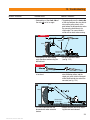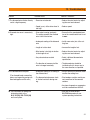
1
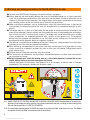
DS-WSS 30 Operating instructions Printed: 08.07.2013 | Doc-Nr: PUB / 5069762 / 000 / 01 en ORIGINAL OPERATING INSTRUCTIONS Congratulations! On purchasing the Hilti DS-WSS 30 wire saw as an addition to the D-LP 32 (30) / DS-TS 32 (30) wall saw system, you have acquired a quality product that provides the highest level of performance, safety and reliability. Uncompromising quality assurance during its manufacture ensures that the system will have a long service life. This manual describes the operating procedures for the DS-WSS 30 only. The saw system functions only in conjunction with the Hilti D-LP 32 hydraulic power unit. Please refer to the D-LP 32 / DS-TS 32 operating instructions for information about operation of the power unit. These operating instructions are intended for the use of concrete cutting service contractors and their experienced personnel, referred to on the following pages as “the operator”. Before operating the Hilti D-LP 32 (30) / DS-TS 32 (30) / DS-WSS 30 wire saw system, the operator must read and understand these operating instructions and receive training from a Hilti specialist. Thanks to its modular design, the DS-WSS 30 wire saw system can be quickly and easily fitted to the standard saw system. Its new design concept, offering maximum convenience and safety in use, opens up an almost endless range of applications in demolition, cutting and remedial work in steel reinforced concrete, masonry and stone. The variable oil flow rate of the D-LP 32 (30) / DS-TS 32 (30) wall saw system used to power the wire saw ensures smooth, gentle starting, and automatic regulation of the wire sawing process and greatly reduces strain on the operator. This system therefore provides the prerequisites for efficient, economical and safe operation. We would like to wish you every success in your work and thank you for placing your confidence in Hilti products. Contents General information 1. General description and technical data for the DS-WSS 30 wire saw 2. General warnings 3. Warnings and safety precautions for the DS-WSS 30 wire saw 4. D-LP 32 (30) / DS-TS 32 (30) modular saw system 5. D-LP 32 (30) / DS-TS 32 (30) / DS-WSS 30 modular wire saw system 6. Setting up the wire saw system 7. Basic applications 8. Diamond wire store 9. Instructions for connecting Hilti DS-W 10.5 diamond wire 10. DS-WSS 30 wire saw system - checks, operation, and sawing procedure 11. Care and maintenance 12. Troubleshooting 13. Disposal of the DS-WSS 30 / D-LP 32 wire saw 14. Manufacturer's warranty – tools 15. EC declaration of conformity (original) 2 Printed: 08.07.2013 | Doc-Nr: PUB / 5069762 / 000 / 01 3 4 6 7 10 10 11 14 19 20 24 27 28 32 33 34 General information The operating instructions must be read carefully before the equipment is put into operation. Always keep these operating instructions with the equipment. The wire saw system should be handed over to other persons only complete with the operating instructions. Obligation signs Wear eye protection. Wear a hard hat. Wear protective gloves. Wear respiratory protection. Wear ear protection. Safety notices and their meaning DANGER Draws attention to imminent danger that will lead to Wear safety footwear. serious bodily injury or fatality. WARNING Draws attention to a potentially dangerous situation Symbols that could lead to serious personal injury or fatality. CAUTION Draws attention to a potentially dangerous situation that could lead to slight personal injury or damage to the equipment or other property. Read the operating instructions before use. NOTE Draws attention to an instruction or other useful information. Explanation of the pictograms and other information A V Amps Volts Warning: electricity Alternating current Watts Diameter Nominal speed under no load Revolutions per minute General warning W Hz no ∅ mm /min rpm STOP Hertz Warning signs Return waste material for recycling. Revolutions per minute Millimeters Stop Warning: avoid hand injuries Warning: Risk of cutting injury 3 Printed: 08.07.2013 | Doc-Nr: PUB / 5069762 / 000 / 01 1. General description and technical data for the DS-WSS 30 wire saw 1.1 System DS-WSW 500 drive wheel DS-WSTA tensioning arm DS-WSWD wire distributor DS-WSRP wire length adjustment pulley DS-WSRF rail support (2×) Drive wheel guard Diamond wire guard DS-WSWS water supply D-LP 32 (30) power unit 1.2 Single-pair pulley stand Fastening spindle/nut for rail support or pulley stand DS-WSSP single-pair pulley stand Water supply to kerf DS-WSW 200 guide pulley 1.2 4 Printed: 08.07.2013 | Doc-Nr: PUB / 5069762 / 000 / 01 1. General description and technical data for the DS-WSS 30 wire saw 1.3 Technical data DS-DS 30 Drive wheel: Guide pulley: Speed (DS-TS 30, 1st gear): Cutting speed: Wire store capacity: Max. diamond wire length: D-LP 32 hydraulic power unit Rated power input at 63A Rated output Rated voltage Ground fault circuit breaker (30 mA) in mains supply on site Max. operating pressure Oil flow rate Dimensions (L×W×H) Weight IP protection code Water cooling with 7 l/min. at max. 6 bar and water temperature 20°C D-RC-LP32 remote control unit Control voltage Dimensions (L×W×H) Weight IP protection code Cable length Cable length with extension Noise information (measured in accordance with EN 15027) Wear ear protection! Mean A-weighted sound power level Mean A-weighted emission sound pressure level at the workplace Uncertainty for the stated sound level: 3 dB (A) 500 mm dia. 200 mm dia. 800 r.p.m. approx. 20 m / sec. 8 m diamond wire 30 m 43 kW 32 kW 400 V / ~ 50 Hz, 3P+N+PE or 3P+PE 210 bar 30–100 l/min 790×540×1090 mm 220 kg IP 44 24 V = (direct current) 390×180×120 mm 2.2 kg IP 65 10 m 20 m LwA 105 dB (A) LpA 85 dB (A) 1.4 Special accessories Special stand with 140 mm dia. plunging pulley Release pulley 5 Printed: 08.07.2013 | Doc-Nr: PUB / 5069762 / 000 / 01 2. General warnings 2.1 Don’t attempt to use the hydraulic saw system and DS-WSS 30 wire saw accessory modules without having received the appropriate training from an authorised Hilti specialist. 2.2 Always use the hydraulic saw system in accordance with the wall saw operating instructions and supplementary wire saw system operating instructions. The operating instructions must always be kept at hand. The instructions on anchoring and securing the system must be observed. 2.3 Approval must be obtained from the site engineer or site management before sawing. Sawing work can negatively affect the stability of a building or other structure, particularly when reinforcing bars or supporting members are cut through. Ensure that there are no concealed gas, water, electricity or other supply lines in the area in which sawing work is to be carried out. 2.4 The area in front of, behind or below the surface where sawing work or drilling is to be carried out must be secured in such a way that persons or equipment cannot be injured or damaged by falling blocks of concrete or by concrete slurry. Where necessary, cores or blocks of concrete should be secured to prevent them from falling. 2.5 Operators and all other persons must stay clear of the area when a load is being lifted by a crane. 2.6 Concrete blocks with a weight of several tons may be sawn out with the Hilti saw. Measures for securing and transporting these concrete blocks must be planned and implemented. Make use of the steel wedges contained in the set of tools for securing concrete blocks. Keep the working area clean and tidy and cordon off openings. 2.7 National regulations and laws, as well as the operating instructions and the safety information applicable to the accessories employed must be observed. 2.8 The D-LP 32 (30) / DS-TS 32 (30) / DS-WSS 30 saw system must NOT be operated in environments where a risk of explosion exists unless special safety precautions are taken. 6 Printed: 08.07.2013 | Doc-Nr: PUB / 5069762 / 000 / 01 3. Warnings and safety precautions for the DS-WSS 30 wire saw 3.1 Make sure sufficient space is available for working safely. If possible, the wire saw should be set up on the floor in an upright position. 3.2 Check the entire system, accessories, power unit, electric cables, hydraulic hoses and accessories for damage and proper functioning before use. Wearing parts, accessories and safety-relevant devices, such as the diamond wire drive wheel, return pulleys, diamond wire and couplings, diamond wire guard and drive wheel guard, end stop, drive wheel mounting screw, hydraulic couplings, etc., must be checked particularly carefully. Check that all parts have been assembled correctly and consider all other factors that could influence operation of the equipment. Contact your Hilti representative or Hilti service centre if faults or deficiencies are found. Repairs to electrical parts must be carried out by a qualified electrical specialist. 3.3 Metal anchors of M12 size should be used for fastening the DS-WSRF rail support and DS-WSSPP single-pair pulley stand. The fastening used must be suitable for the base material in question and must not work loose. Suitable Hilti anchors are, e.g. HKD-D, HSA-A, HIT or HEA. If masonry is loose or crumbling, we recommend that through holes are drilled and M16 threaded rods with clamping nuts used for fastening. 3.4 Fastening screws of at least 8.8 grade as per ISO should be used for the rail supports or, alternatively, use the DD-CS M12 S-SM clamping spindle with DD-CN-SML quick-release clamping nut. 3.5 An end stop must always be fitted at the end of the rail to prevent unintentional advance beyond this point (prevents the saw head coming off the end of the rail). 3.6 It is essential that the specified checks are carried out before sawing. 3.7 The drive wheel guard (see fig. 3.7, no. 1) and diamond wire guard (see fig. 3.7, no. 2) MUST ALWAYS BE FITTED when the saw is in use. These guards prevent parts flying out in the direction of tension should the diamond wire break. NEVER stand in a position in line with the diamond wire while the saw is running. 3.7 2 1 1 2 3.8 ■ Safety measures must be implemented in the area where sawing is taking place so that operators and bystanders cannot be injured or property damaged by a broken sawing wire or debris that may fly off during the sawing operation (wire connectors, diamond beads, spacing springs, small stones, sawing slurry, etc.). Safety measures must also be implemented in the area not directly visible to the operator, i.e. behind where sawing is taking place. 7 Printed: 08.07.2013 | Doc-Nr: PUB / 5069762 / 000 / 01 3. Warnings and safety precautions for the DS-WSS 30 wire saw ■ Persons must NEVER enter the danger area while sawing is in progress. ■ Always keep the free wire lengths between the drive unit and object being cut as short as possible (max. 3.5 m) and mount guide pulleys at the wire entry and exit points in order to reduce the risk of whiplash in the event of wire breakage. The whiplash effect causes great acceleration of the sawing wire, resulting in parts of the wire lashing out or flying off with great force. ■ Make sure there are no objects such as scaffolding etc. within the wire whiplash area. In the event of wire breakage, the whiplashing end of the wire may be deflected in an unexpected direction by such objects. ■ The danger area has a radius of at least twice the free length of wire that would be unleashed in the event of wire breakage (shown in yellow) and also includes the areas in the extended axes of the direction in which the wire is running (shown in gray). The danger area cannot be limited unless suitable means of protection are employed (protective walls, curtains or wire guards etc.). The protective devices must be arranged and mounted in a way that stops the wire lashing out in the event of wire breakage and reliably prevents objects or fragments flying off. ■ The operator is responsible for cordoning off the area. If necessary, safety personnel must be posted to prevent access to a wide area around the workplace ■ When setting up and operating the saw system and when removing parts that have been cut away, always ensure that no persons are below the area in which you are working. Falling objects could cause serious injury. ■ Children must be instructed not to play with the machine. ■ The machine is not intended for use by children, by debilitated persons or those who have received no instruction or training. ■ Before beginning work, check the working area (e.g. with a metal detector) to ensure that no concealed electric cables or gas and water pipes are present. External metal parts of the machine may become live if, for example, an electric cable is damaged inadvertently. This presents a serious risk of electric shock. 3.8 r 2 =l 2 x 2 l2 l1 =l r1 1 2 276377 05.06 x 3.9 ALWAYS SWITCH OFF THE WIRE SAW BEFORE ADJUSTING THE WATER SUPPLY. Readjustment of the water supply nozzle at the single-pair pulley stand or at any other position while the saw is running, in order to bring it into line with the diamond wire, is STRICTLY PROHIBITED. 3.10 The wire length adjusting pulley (DS-WSRP wire store) must always be fitted, even when not in use. The flexible wire guard can then be fitted in accordance with the instructions. 8 Printed: 08.07.2013 | Doc-Nr: PUB / 5069762 / 000 / 01 3. Warnings and safety precautions for the DS-WSS 30 wire saw 3.11 Never connect or disconnect hydraulic hoses while the power unit is running or while the hoses are under pressure. 3.12 Wear suitable clothing. Don’t wear loose clothing or jewellery which could become caught in moving parts of the machinery. Wear a hard had, protective goggles, protective gloves, safety shoes, ear protectors and a hairnet if you have long hair. A face mask should be worn to protect the respiratory system when working in enclosed areas. 3.13 Avoid body positions in which the back is bent when carrying motor units or other heavy components. Maintain a secure stance and always stay in balance, especially when using ladders or when working from scaffolding. 3.14 Check all screws on the DS-TS 32 (30) saw, tensioning arm, diamond wire guard and drive wheel guard which could work loose due to vibration. 3.15 Disconnect the electric extension cable from the mains supply when the equipment is not in use, during transport and before inspection or maintenance. Ensure that the hydraulic power unit is switched off before changing the diamond wire or before adjusting the position of the guide pulleys. As an additional safety measure, it is recommended that the EMERGENCY STOP button is pressed and left in the OFF position. 3.16 Use of the Hilti diamond wire saw system is permitted only in conjunction with the other DS-WSS 30 components listed in these instructions. The use of individual components for wire sawing, e.g. only the drive wheel, is prohibited as this could present a serious hazard to the operating personnel. 3.17 For further information, please refer to the D-LP 32 (30) / DS-TS 32 (30) operating instructions. 9 Printed: 08.07.2013 | Doc-Nr: PUB / 5069762 / 000 / 01 4. D-LP 32 (30) / DS-TS 32 (30) modular saw system comprising: DS-TS32 D-PH34-10 (2x) D-FH4/14-10 1 D-LP 32 (30) 2 D-RC- LP 32 (DS-CB) 7 3 D-PH34-10 (2x) 3 /4 4 D-FH4/14-10 5 DS-RF 6 6 DS-R 230L DS-R 230L 7 DS-TS32 (30) D-RC-LP 32 1 5 DS-RF DS-RF D-LP 32 2 5. D-LP 32 (30) / DS-TS 32 (30) / DS-WSS 30 modular wire saw system DS-WSS30 comprising: 7 1 2 3 4 DS-WSW500 DS-WSTA DS-WSWD DS-WSRP 3 2 5 2x DS-WSRF 6 DS-WSWS 7 2x DS-WS-SPP DS-W10.5 1 7 4 5 10 Printed: 08.07.2013 | Doc-Nr: PUB / 5069762 / 000 / 01 6 6. Setting up the wire saw system 6.1 Through-holes for the diamond wire – Plan the working procedure carefully and precisely before beginning to install the system and before drilling the through-holes. – Drill the through-holes for the diamond wire (see fig. 6.1, no. ). Use a suitable drilling machine, depending on the situation and the base material: 킞 Combihammer TE 70 with 16 mm dia. drill bit 킞 Diamond drilling machine DD 200 with the core bit DD-BS 52 6.2 Fastening to the base material WARNING Use an anchor suitable for the material on which you are working and observe the anchor manufacturer’s instructions. NOTE Hilti M12 metal expansion anchors are usually suitable for fastening diamond core drilling equipment to uncracked concrete. Under certain conditions it may be necessary to use an alternative fastening method. Please contact Hilti Technical Service if you have any questions about secure fastening. – Rigid and secure fastenings are the basic prerequisite for efficient and safe sawing. We recommend the use of Hilti drilling and anchoring systems. – Fasteners suitable for the base material in question should be used to fasten the rail supports and single-pair pulley stands. For example, a minimum edge distance of 18 cm must be observed when setting the Hilti HKD M12 metal expansion anchor. As a general rule, this anchor should be set ≥ 5 mm below the surface of the concrete. After drilling the hole, the dust should be blown out. – Hilti HIT adhesive anchors can be used in masonry etc. or, alternatively, through-holes drilled and threaded rods used. 6.3 Recommended fastening method using the clamping spindle and clamping nut For fastening the rail supports and single-pair pulley stands, Hilti recommends use of the HKD-D anchor in conjunction with the double-thread clamping spindle and clamping nut with pivoting baseplate. Advantages 1. Flexible clamping nut / baseplate provides secure fastening even on uneven surfaces and when anchor holes are drilled at an angle. 2. Coarse thread pitch for rapid assembly and disassembly 3. The anchor can be set deeper. 6.1 Clamping nut with pivoting baseplate Double-thread clamping spindle 6.2 Through-hole for the diamond wire 11 Printed: 08.07.2013 | Doc-Nr: PUB / 5069762 / 000 / 01 6. Setting up the wire saw system 6.4 Recommended fastening set Advantages ■ Can be set deeper: special HKD-D anchor without collar ■ High holding power: HKD-D M12 metal expansion anchor with 16 mm outside diameter ■ Flexible clamping nut / baseplate for secure fastening even when anchor holes are drilled at an angle or on uneven surfaces ■ Coarse thread pitch for rapid assembly and disassembly ■ Avoids damage to the baseplate or rail support Accessories for fastening the wire saw and pulley stands Description Combihammer Hammer drill bit Blow-out bulb Flush anchor Manual setting tool Clamping spindle Clamping nut Use Package contents Drilling anchor holes Drilling anchor holes Cleaning anchor holes Fastening the wire saw / pulley stands Expanding the anchors Fastening the wire saw / pulley stands Fastening the wire saw / pulley stands 1 1 1 50 1 1 1 Ordering designation Item no. TE70 TE-YX-16/35 BB HKD-D M12x50 HSD-G M12x50 DD-CS M12 S-SM DD-CN-SML 000000 333760 059725 252961 243743 251830 251834 Accessories for drilling through holes Description Use Combihammer Hammer drill bit Hammer drill bit Pointed chisel Diamond coring machine Diamond core bit Extension Drilling through holes Drilling through holes Drilling through holes Rounding edges of holes Drilling through holes Drilling through holes Drilling through holes Package contents 1 1 1 1 1 1 1 Ordering designation TE 70 TE-YX 16/55 TE-YX 16/92 TE-YP-SM28 DD 200 DD BS52/430 11/4 " UNC Item no. 000000 333761 370564 282263 ! 000000 " 000000 # 009850 ! " Diamond coring is recommended for corner holes in very thick walls, in heavily reinforced concrete and where very precise cuts must be made. # 12 Printed: 08.07.2013 | Doc-Nr: PUB / 5069762 / 000 / 01 6. Setting up the wire saw system DSW-WG wire guards DS-WSRW release pulley (Item no. 365426) (Item no. 315834) Wire guards must be fitted in situations where it cannot be ensured that persons do not enter the area in which flying objects present a risk of injury while the equipment is in operation or where there is a risk of damage to property or other equipment within this area. When wire guards are used, check to ensure they are fitted correctly. The release pulley is used to reduce the length of wire in contact or to increase the radius of the arc followed by the wire (avoiding a tight radius) at the rear of the object to be cut. DSW-PW plunge wheel (Item no. 365428) DS-WS-SPP single-pair pulley stand For plunge applications of all kinds. At least 2 are required. Can also be mounted on the single-pair pulley stand if necessary. (Item no. 365427) In applications where, due to restricted access, it is impossible to mount the compact wire saw directly on the object to be cut or where longer cuts of up to a maximum of 2 meters are to be made, the sawing wire is guided to the cutting face by the pulley stand. DS-WSS 30 guard (Item no. 276388) DS-WSS 30 guard (Item no. 276379) 13 Printed: 08.07.2013 | Doc-Nr: PUB / 5069762 / 000 / 01 7. Basic applications 7.1 Standard vertical cut Water – Optimum cutting length – No tight diamond wire radius in the concrete – Average cutting performance – Normal rate of wire wear Water 2 1 1st step – Relatively short cutting / contact length – High cutting performance – High rate of wire wear Note When the kerf is at the height of pulley , the pulley should be turned and positioned below the wire. Release pulley 7.2 Vertical cut with release pulley Water Diamond wire Tension side Water 2 1 Diamond wire Tension side Note At the end of the cut, when the diamond wire is pulled out of the kerf, it is caught by pulleys and . – No danger of the wire lashing back – Avoids damage to the wire Release pulley 2nd step Water 2 1 Diamond wire Tension side Note The optimum cutting length for the Hilti DS-WSS 30 wire saw system is 1 to 4.5 metres, i.e the diamond wire is in contact with the workpiece over a length of 1 to 4.5 metres. 14 Printed: 08.07.2013 | Doc-Nr: PUB / 5069762 / 000 / 01 7. Basic applications 7.3 Standard horizontal cut Wall saw 7.4 Flush horizontal cut A At the beginning of the cut Pivoting pulley with ball-bearing pivot Pivoting pulley with ball-bearing pivot 15 Printed: 08.07.2013 | Doc-Nr: PUB / 5069762 / 000 / 01 7. Basic applications B At the end of the cut Pivoting pulley with ball-bearing pivot Pivoting pulley with ball-bearing pivot Side view Pivoting pulley Saw kerf Diamond wire Note In order to prevent the diamond wire from jumping off the pivoting guide pulleys, we recommend that the wire saw is switched off shortly before completing the cut and that a combihammer is used to break away the small amount of remaining material. 16 Printed: 08.07.2013 | Doc-Nr: PUB / 5069762 / 000 / 01 7. Basic applications 7.5 Aligning the guide pulleys As a general rule, all guide pulleys must be aligned with each other so that the diamond wire always runs in the middle of the pulley (minimises pulley wear and reduces the risk of the diamond wire jumping off). 7.5 Water Slack side Water Exception Two guide pulleys on the slack side, between the wire distributor pulleys and the pulley stand at the point the diamond wire enters the concrete, should be set up at a slight angle (see fig. 7.5). This assists the diamond wire to rotate about its own axis while cutting, thereby achieving more even wear. 2 1 Diamond wire Tension side 7.6 Flush cutting – For flush cutting, the pulleys with ball-bearing pivot must always be used. These pulleys are designed to pivot easily and follow the movement of the diamond wire. They can be easily differentiated from the type with plain bearings (see fig. 10.3). – The pulleys with ball-bearing pivot should always be positioned at the points where the diamond wire enters or leaves the concrete. 7.6 Pulley with ball-bearing pivot Pulley with ball-bearing pivot Diamond wire Plain bearing Can be clamped in position Clamping screw Loosen screw for flush cutting Clamping screw Ball bearing Pivoting pulley Kerf 17 Printed: 08.07.2013 | Doc-Nr: PUB / 5069762 / 000 / 01 7. Basic applications 7.7 Wire saw application using plunging pulleys Special stands 7.7a 7.7b Pivoting pulleys (to saw head) 200 mm dia. Pivoting pulleys (to saw head) 200 mm dia. Hole 162 mm dia. Hole ∅ 162 mm Length of cut Length of cut Tubular extension 2″ dia. Tubular extension 2″ dia. Tubular extension 2″ dia. Radius at end of cut Tubular extension 2″ dia. Radius at end of cut 20–30 cm 20–30 cm Pivoting plunging pulleys 140 mm dia. Pivoting plunging pulleys 140 mm dia. 7.7c Pivoting pulleys (to saw head) 200 mm dia. Length of cut Tubular extension 2″ dia. Radius at end of cut Pivoting plunging pulleys 140 mm dia. Tubular extension 2″ dia. 20–30 cm Desired depth of cut 7.7d Note When cutting over a length of 2–3 m, the plunging pulleys must always be positioned 20 to 30 cm below the desired depth as a slight curve always remains at the end of the cut. 18 Printed: 08.07.2013 | Doc-Nr: PUB / 5069762 / 000 / 01 8.Diamond wire store The built-in return pulley and wire store pulley can be used to reduce the effective length of the diamond wire by up to 8 m with a rail length of only 2 m (DS-R 200 L). Configuration 1 2×1.5 m =3m Configuration 2 Drive wheel guard End stop Diamond wire guard + Wire length adjusting pulley 2×0.5 m =1m Configuration 3 2 m rail (DS-R200L) + 2×0.5 m =1m Configuration 4 + 2×1.5 m =3m Total 8 m Important No matter how the wire saw is set up, the DS-WSRP wire length adjusting pulley must always be fitted and the diamond wire guard belonging to it attached at the bottom of the drive wheel guard. 19 Printed: 08.07.2013 | Doc-Nr: PUB / 5069762 / 000 / 01 9. Instructions for connecting Hilti DS-W 10.5 diamond wire Cutting direction Important: The connectors must be fitted, relative to the cutting direction, as shown in the illustration. The diamond wire must be used to cut in one direction only (see arrows). Preparations for the first cut ■ Connectors are already fitted to new diamond wires. ■ The diamond wire must be twisted before joining the connectors by inserting the pin. Twist the diamond wire, approx. 1–1.5 turns per metre length of wire, in a counter-clockwise direction (to the left) as seen when looking straight at the cut face of the end of the wire. ■ The corners on the workpiece should be rounded off to a radius of approx. 10 cm (using a hammer and chisel or a Hilti combihammer) and/or the diamond wire pulled through by hand. ■ Mount the water supply nozzle at the point where the wire enters the workpiece. Depending on the length of the cut, it may be necessary to apply cooling water at several points. It is essential that the wire is cooled perfectly if good cutting results are to be achieved. ■ Use the advance movement to tighten the wire. Move away from the machine to a safe distance and start the motor. Start the saw gently and then increase the running speed gradually until the optimum drive speed (r.p.m.) and cutting speed is reached. ■ The sawing operation must be monitored continuously. ■ The wire saw must be stopped before making adjustments to the water supply nozzles. General information ■ Do not kink or bend the wire sharply. ■ Do not join diamond wires of different diameters together. ■ To ensure even wear of the beads, the diamond wire must be retwisted after each long cut, applying a different number of turns, before beginning the next cut. 20 Printed: 08.07.2013 | Doc-Nr: PUB / 5069762 / 000 / 01 9. Instructions for connecting Hilti DS-W 10.5 diamond wire Instructions for fitting DS-WC connectors 1 2 (Item no. 340427) 13 mm Fitting the connector (first 10 mm end, clevis piece) Clamp the diamond wire 3 in the vice with the cutting direction as shown (see arrow) and use an 10 mm angle grinder to cut off the end 13 mm from the first bead. 4 Use pliers to remove the y x spring (pull out). Remove the rubber neatly over a length of 10 mm (using a knife, cigarette lighter or wire brush). Fit an O-ring 쩸 (Item no. 5 235844) pushing it onto the wire until seated against the bead. Fit the c clevis piece 쩹 onto the 1 mm wire so that the end of the bare wire section contacts the base of the hole. Use the crimping pliers 쩺 (Item no. 235845) and the corresponding crimping jaws to crimp the connector fully in one operation. When doing so, the crimping jaws should be positioned 1 mm from the end of the connector. Worn or deformed crimping jaws should not be used. Fitting the connector (second end, opposite piece) and joining the connectors ■ To fit and crimp the second part of the connector (opposite piece) proceed as described at steps to . ■ Joining the connectors Twist the diamond wire, approx. 1–1.5 turns per metre length of wire, in a counterclockwise direction (to the left) as seen when looking straight at the cut face of the end of the wire. Bring the connectors together and insert the pin (item no. 235842) using a hammer to drive it in flush. Opening the connectors ■ Use a punch to drive the pin out of the connector. Replace the pin if it is badly worn (replacement pin, item no. 235842). 21 Printed: 08.07.2013 | Doc-Nr: PUB / 5069762 / 000 / 01 9. Instructions for connecting Hilti DS-W 10.5 diamond wire Instructions for fitting DS-WS repair sleeves A (Item no. 235841) 13 mm Fitting a repair sleeve (first end) Important: The service life of B the connectors is several times that of the repair sleeve. A Clamp the diamond wire in the vice and use an angle grinder to cut off 10 mm the end 13 mm from the C first bead. B Use pliers to remove the spring (pull out). 10 mm C Remove the rubber neatly over a length of 10 mm (using a knife, cigarette lighter or wire brush). D y v D Fit an O-ring 쩸 (Item no. 235844) pushing it onto the wire until seated against the bead. Fit a repair sleeve 쩺 onto the wire so that the end of the bare wire section contacts E c the base of the hole. E Use the crimping pliers 쩺 (Item no. 235845) and the corresponding crimping jaws to crimp the connector fully in oneoperation. When doing so, the crimping jaws should be positioned 1 mm from the end of the connector. Worn or deformed crimping jaws should not be used. Fitting a repair sleeve (second end) ■ Proceed as described at steps A to C . ■ Twist the diamond wire, approx. 1–1.5 turns per metre length of wire, in a counterclockwise direction (to the left) as seen when looking straight at the cut face of the end of the wire. ■ Proceed as described at steps D to E . 22 Printed: 08.07.2013 | Doc-Nr: PUB / 5069762 / 000 / 01 9. Instructions for connecting Hilti DS-W 10.5 diamond wire Hilti sawing wires and accessories Recommendations: Which specification for which material? Standard diamond wires (sintered beads) BC LC Material Reinforced concrete Desired characteristics Fast cutting Long life Special wires (electroplated beads) Steel 20% Steel 100% Heavily reinforced Solid steel concrete – – DS-W10.5 diamond wires Hilti DS-W10.5 diamond wires for DS-W15, DS-WS 30 and DS-WS10 wire saw systems Wire length (m) Designation DS-W 10.5 BC 10 m 235835 * 14 m 235836 * 18 m 315019 * 22 m 315022 * 26 m 315025 * 30 m 315028 * 50 m 370500 100 m 370426 150 m 376633 per/m 376635 * with factory-fitted flexible connectors DS-W 10.5 LC DS-W 10.2 steel 20% DS-W 10.8 steel 100% 235834 * 235838 * 315020 * 315023 * 315026 * 315029 * 376630 376631 376632 376634 – 376982 371983 371984 – – 371985 371986 373130 377830 – 371987 371988 371989 – – 371990 371991 – 377781 Accessories for Hilti diamond wires Designation Use Package contents Crimping pliers For crimping connectors / repair sleeves 1 Flexible connectors Quick-release type 1 Set of flexible connectors* Quick-release type with pin and O-ring 5 Replacement pin for quick-release connectors10 Pin Sleeve Repair sleeve 5 Fitted between connector and bead 10 O-ring Crimping jaws Replacement jaws for crimping pliers 2 For cutting diamond wire 1 Angle grinder * Includes a special tool for opening the flexible connector Ordering designation DS-WSTHY DS-WCMV DS-WCSet DS-WP DS-WS O-ring 10/4.7×2.5 DS-WJ AG 125-S Item no. 235845 340427 371383 235842 235841 235844 340426 000000 23 Printed: 08.07.2013 | Doc-Nr: PUB / 5069762 / 000 / 01 10. DS-WSS 30 wire saw system - checks, operation and the sawing procedure 10.1 Checks before sawing – The rail supports and guide pulley stands must be correctly fastened (all screws tightened securely. – The saw head must be mounted without play, the saw arm in the vertical position (at 90° to the rail), the camaction rollers engaged (DS-TS 30 1st gear). – The wire tensioning pulley and drive wheel guard must be fitted and secured in position with the clamping screw at the side of the blade guard holder. – The drive wheel must be fitted and secured with the standard saw blade flange and central mounting screw. – The drive wheel guard cover must be fitted. – The wire distributor assembly must be fitted at the front end of the rail using the standard rail taper and eccentric pin. – The end stop must be fitted at the rear end of the rail. – The wire length adjusting pulley and rolled-up diamond wire guard must be fitted and the rubber diamond wire guard attached to the drive wheel guard. – The hydraulic hoses and water hoses must be connected correctly. (The two control hoses for the saw arm plunge movement do not have to be connected as only the longitudinal advance movement is required for wire sawing.) – Electric power and water must be available. The EMERGENCY STOP buttons on the hydraulic power unit and remote control unit must be disengaged (pulled out) and all controls on the electric remote control unit set to the OFF / 0 or neutral position. – The working area must be cordoned off. All safety distances must be observed. – The diamond wire must be connected correctly, aligned properly and it must be possible to pull the wire through easily by hand. 60 40 80 1600 1200 1000 900 100 800 mm D-RC-LP 32 II 45 I 32 63 Ampere 32-50 A 24 Printed: 08.07.2013 | Doc-Nr: PUB / 5069762 / 000 / 01 Start 10. DS-WSS 30 wire saw system - checks, operation and the sawing procedure 3 4 7 60 40 8 9 80 1600 1200 1000 900 2 100 800 mm D-RC-LP 32 II 45 Start I 32 63 Ampere 6 1 10 5 10.2 Remote control unit: controls Pos.1: Electric motor ON (I 킞 II 킞 Start 킞 Release 킞 II) Electric motor OFF (II 킞 I) Pos.2: Hydraulic oil flow rate 0–100 l /min. (controls speed of diamond wire drive wheel) Pos.3: Plunge movement (right / left). As the control hoses necessary for this function may not be connected to the wall saw when used for wire sawing, this rotary switch has no function. Pos.4: Advance (right / left, diamond wire tension / release tension) Pos.5: Speed of advance for (4) Pos.6: Power input setting in amps, depends on mains supply Pos.7: EMERGENCY STOP button 10.3 Remote control unit: starting and operating the saw system 1. Adjust the current (6) to a value between 32 amps and approx. 50 amps depending on the mains supply available on the jobsite. 2. Switch on the water supply. 3. Knobs (3), (4), (5) and (7) should be set to the «0» (neutral position). Switch on the electric motor (1) and check that the hydraulic unit switches from star to delta (takes approx. 2–5 seconds). 4. Use the longitudinal advance control (4) to select the correct direction of movement for wire tension and use the advance speed control (5) to tension the diamond wire slightly. 5. Use the potentiometer (2) to start the drive wheel motor slowly and, at the same time, adjust the advance speed control knob (5) in order to maintain or increase tension on the diamond wire. As soon as the diamond wire is running correctly, the speed of the drive wheel can be increased to maximum, by adjusting the potentiometer (2). This corresponds to a speed of 800 r.p.m. The cutting speed of the diamond wire is then 20 m / sec. Subsequently, only the advance speed control (5) requires adjustment in order to control the diamond wire tension and, thus, the sawing performance. A visible indication of correct tension is given by the wire tensioning arm, which should rise approx. 10 to 15 cm. The saw should be operated at a pressure of approx. 120 bar (max. 140 bar) in the main hydraulic circuit in order to achieve optimum sawing performance without excessive strain on the diamond wire. 25 Printed: 08.07.2013 | Doc-Nr: PUB / 5069762 / 000 / 01 10. DS-WSS 30 wire saw system - checks, operation and the sawing procedure Once initially set, the system regulates itself by way of the automatic advance system. This means that when the diamond wire encounters heavy reinforcement, the drive unit advance speed is reduced automatically until the reinforcement is cut trough. The rate of advance then returns automatically to the speed previously set. 10.4 1. 2. 3. 4. Switching off the saw system Switch off the saw advance control – turn the knob (4) to the “0” or neutral position Switch off the drive wheel motor – turn the knob (2) to the “0” position. Switch off the electric motor – turn the knob (1) to the “I” position. Press the EMERGENCY STOP button. 26 Printed: 08.07.2013 | Doc-Nr: PUB / 5069762 / 000 / 01 11. Care and maintenance CAUTION Disconnect the supply cord plug from the power outlet. CAUTION Keep the machine, especially its grip surfaces, clean and free from oil and grease. Do not use cleaning agents which contain silicone. 11.1 Cleaning using high-pressure or steam-cleaning systems Avoid directing the jet towards the bearings and seals when systems of this kind are used for cleaning the guide pulley stands and saw head. 11.2 Maintenance of the single-pair pulley stand As the guide pulleys used for flush cutting are equipped with two ball bearings at the pivot, these should be lubricated at least once a month. Procedure: Unscrew the locking bolt completely and inject a little oil into the threaded opening. Reinsert the bolt (see fig. 11.2). 11.2 Locking bolt 11.3 Rubber rim on the pulleys The rubber rim on the drive wheel and guide / return pulleys should be checked at regular intervals. A wheel or pulley should be replaced as soon as the aluminium beneath the rubber is visible (rubber worn through). 11.4 Diamond wire guard and drive wheel guard These parts should be cleaned daily and checked to ensure that the rolling-up mechanism of the diamond wire guard always functions correctly. 11.5 Maintenance of the hydraulic power unit, saw head and other saw modules Please refer to the D-LP 32 (30) / DS-TS 32 (30) operating instructions. 27 Printed: 08.07.2013 | Doc-Nr: PUB / 5069762 / 000 / 01 12. Troubleshooting Persons may enter the danger zone only when the Disconnect the equipment from the electric supply drive unit is switched off and the drive pulley has stop- (unplug the supply cord from the power outlet) before ped rotating. Press the EMERGENCY STOP button opening the control unit. before entering the danger zone. Problem Possible cause Solution / measures 1. The diamond wire does not run. – Corners on concrete too sharp – Use a Hilti combihammer to break away sharp corners and ensure that the diamond wire can be moved to and fro initially by hand. – A new diamond wire is being used in a cut made by a worn diamond wire. – Use the worn wire to finish the cut. – Drill an additional hole where the new wire can be pulled through. – The section of diamond wire in con- – Additional guide pulleys must be installed. tact with the concrete is too long. 2. The diamond wire slips on the drive wheel. 3. The diamond wire is badly worn, irregularly and on one side. – Excessive tension on the diamond wire – Reduce wire tension by adjusting the saw head advance (observe the tensioning arm). – Insufficient tension on the diamond wire – Increase wire tension by adjusting the saw head advance. (Observe the tensioning arm.) – Insufficient length of contact between the wire and drive wheel perimeter. – Adjust the guide pulleys to increase the length of contact between the wire and drive wheel perimeter. – The section of wire in contact with the concrete is too long. – Additional guide pulleys must be installed. – The rubber rim on the drive wheel is too badly worn. – Replace the drive wheel. – Diamond wire not twisted before coupling the ends together – Twist the wire in a counter-clockwise direction (as seen when looking straight at the cut end of the wire) approx. 1–1.5 turns for each metre length of wire. – The wire must be retwisted after each large cut by applying a different number of turns. 28 Printed: 08.07.2013 | Doc-Nr: PUB / 5069762 / 000 / 01 12. Troubleshooting Solution / measures Possible cause Solution / measures – Guide pulleys at the slack side of the wire not set at an angle – The guide pulleys on the slack side of the wire between the wire distributor and the pulley stand, at the point where the diamond wire enters the concrete, should be set at a slight angle. This causes the diamond wire to rotate when running. 12.3 RIGHT! Water Slack side Water 2 1 Diamond wire Tension side – Guide pulleys set at the wrong angle therefore counteracting the desired twist – Set up as explained above (see fig. 12.3). WRONG! – The slack side of the diamond wire – Increase the distance between the is too short. wire distributor pulleys and the single-pair pulley stand at the point where the diamond wire enters the concrete (see fig. 12.4). 12.4 Water Water 2 1 Diamond wire Tension side – The saw is operated with the diamond wire under excessive tension. – Reduce the wire tension by adjusting the saw head advance. 29 Printed: 08.07.2013 | Doc-Nr: PUB / 5069762 / 000 / 01 12. Troubleshooting Problem Possible cause Solution / measures 4. The wire breaks immediately beside the coupling – The cutting radius of the diamond wire in the concrete is too small. – Install additional guide pulleys. – The wire has been used too long under excessive tension. – Reduce the wire tension by adjusting the saw head advance. Don’t exceed the specified pressure of 120–160 bar in the main hydraulic circuit. – The wire coupling is too long. – Fit shorter wire couplings. – Use the cardan-type, flexible couplings recommended by Hilti. 5. The diamond wire is pulled out of the crimped coupling. 6. The diamond wire thrashes about and vibrates badly. 30 Printed: 08.07.2013 | Doc-Nr: PUB / 5069762 / 000 / 01 – Crimping pliers incorrectly adjusted – Check the setting of the crimping pliers. – Insufficient pressure applied to the crimping pliers – Use Hilti crimping pliers with a minimum pressure of 7 t. – Incorrect or worn crimping jaws – Check the crimping jaws and replace if necessary. – The wire was not pushed far enough into the coupling. – With all couplings available from Hilti, the wire must always be pushed in as far as it will go. – Constantly excessive wire tension during operation. – Reduce the wire tension by adjusting the saw head advance. – Insufficient wire tension – Increase wire tension by adjusting the saw head advance. – The pulley stands are too far apart (excessively long unsupported wire length). – Install additional guide pulley stands. – Fit a shorter diamond wire. – Rail support incorrectly positioned – The front rail support (at the wire distributor) should be fitted as close as possible to the end of the rail. 12. Troubleshooting Problem Possible cause Solution / measures 7. The diamond wire vibrates fiercely and at a high frequency. – Excessive wire tension – Reduce the wire tension by adjusting the saw head advance. – Speed (r.p.m.) of the drive wheel is too high. – Reduce speed – Drive wheel running too slowly. The cutting speed of the diamond wire is thus also too low. – Ensure that the speed potentiometer on the remote control unit is set to max. – Inadequate cooling of the diamond wire – Install more water jets at the cutting face. – Length of cut too short – Increase the length of cut. – Wire tension is too high in relation to the length of cut. – Reduce the wire tension by adjusting the saw head advance. – Very abrasive base material – Select a different diamond wire specification. – The direction of movement of the wire is changed constantly. – The diamond wire should be installed so that it always runs in the same direction, as specified. – Inadequate cooling or no cooling of the diamond wire – Always ensure that sufficient water reaches the cutting face. – The diamond wire becomes stuck in the kerf and stalls during sawing. – Steel wedges must be used to prevent movement of the concrete sections. 8. Diamond wire wear is excessively high. 9. The diamond wire collapses. (The diamond beads, connecting pieces and separating springs are bunched together on the wire.) – Any loose fragments or aggregates must be removed from the kerf. 10. For information on finding and eliminating faults in the D-LP 32 (30) / DS-TS 32 (30) wall saw system. – Also refer to the D-LP 32 / DS-TS 32 diamond wall saw system operating instructions. 31 Printed: 08.07.2013 | Doc-Nr: PUB / 5069762 / 000 / 01 13. Disposal Return waste material for recycling Most of the materials from which Hilti appliances are manufactured can be recycled. The materials must be correctly separated before they can be recycled. Hilti has already made arrangements in many countries for taking back your old appliance for recycling. Please ask your Hilti customer service department or a Hilti sales representative for further information. Only for EU countries Do not dispose of electric tools together with household waste material! In observance of European Directive on waste electrical and electronic equipment and its implementation in accordance with national law, electric tools that have reached the end of their life must be collected separately and returned to an environmentally compatible recycling facility. Disposal of drilling and sawing slurry NOTE With regard to environmental aspects, allowing drilling or sawing slurry to flow directly into rivers, lakes or the sewerage system without suitable pre-treatment is problematical. In addition to the following recommended pretreatment procedures, the applicable national regulations must be observed when disposing of drilling or sawing slurry. Ask the local authorities concerned for further information. We recommend the following pre-treatment 1. Collect the drilling and sawing slurry (e.g. using a suitable industrial vacuum cleaner). 2. The fine content of the drilling and sawing slurry should be separated from the water by allowing it to settle (e.g. leave standing for some time or add a coagulation agent). 3. Solid material from the drilling and sawing slurry should be deposited at a construction waste disposal site. 4. Water from the drilling and sawing slurry should be neutralized (e.g. by adding a large quantity of water or other neutralization agents) before it is allowed to flow into the sewerage system. 32 Printed: 08.07.2013 | Doc-Nr: PUB / 5069762 / 000 / 01 14. Manufacturer's warranty – tools Hilti warrants that the tool supplied is free of defects in material and workmanship. This warranty is valid so long as the tool is operated and handled correctly, cleaned and serviced properly and in accordance with the Hilti Operating Instructions, and the technical system is maintained. This means that only original Hilti consumables, components and spare parts may be used in the tool. This warranty provides the free-of-charge repair or replacement of defective parts only over the entire lifespan of the tool. Parts requiring repair or replacement as a result of normal wear and tear are not covered by this warranty. Additional claims are excluded, unless stringent national rules prohibit such exclusion. In particular, Hilti is not obligated for direct, indirect, incidental or consequential damages, losses or expenses in connection with, or by reason of, the use of, or inability to use the tool for any purpose. Implied warranties of merchantability or fitness for a particular purpose are specifically excluded. For repair or replacement, send tool or related parts immediately upon discovery of the defect to the address of the local Hilti marketing organization provided. This constitutes Hilti's entire obligation with regard to warranty and supersedes all prior or contemporaneous comments and oral or written agreements concerning warranties. 33 Printed: 08.07.2013 | Doc-Nr: PUB / 5069762 / 000 / 01 15. EC declaration of conformity (original) Description: Designation: Year of design: Hydraulic saw system DS-WSS 30 / D-LP 32 2001 We declare under our sole responsibility that this product complies with the following directives and standards: 2006/42/EG, 2004/108/EG, 2011/65/EU, EN ISO 12100, EN 60204-1 This equipment complies with the applicable standard provided that the short-circuit power SSC at the interface point between the user’s supply and the public supply network is greater than or equal to 3.2 MVA. It is the responsibility of the installer or user of the equipment to ensure, by consultation with the supply network operator if necessary, that the equipment is connected only to a supply with a short-circuit power SSC of greater than or equal to 3.2 MVA. Hilti Corporation, Feldkircherstrasse 100, FL-9494 Schaan Paolo Luccini Head of BA Quality and Process Management Business Area Electric Tools & Accessories Johannes Wilfried Huber Senior Vice President Business Unit Diamond 02 / 2012 02 / 2012 Technical documentation filed at: Hilti Entwicklungsgesellschaft mbH Zulassung Elektrowerkzeuge Hiltistrasse 6 86916 Kaufering Deutschland 34 Printed: 08.07.2013 | Doc-Nr: PUB / 5069762 / 000 / 01 35 Printed: 08.07.2013 | Doc-Nr: PUB / 5069762 / 000 / 01 Hilti Corporation Hilti = registered trademark of Hilti Corp., Schaan W 2270 I 1212 I 1-en I 1 Printed in Liechtenstein © 2012 Right of technical and programme changes reserved S. E. & O. Printed: 08.07.2013 | Doc-Nr: PUB / 5069762 / 000 / 01 315911 / A3 *315911* 315911 LI-9494 Schaan Tel.: +423 / 234 21 11 Fax: +423 / 234 29 65 www.hilti.com