1
Maintenance Guide
Read This First
Trademarks.............................................................................................................3
How to Read This Manual .....................................................................................4
Paper and Other Media
Paper and Other Media Supported by This Printer.............................................5
Paper Recommendations......................................................................................9
Loading Paper............................................................................................................9
Storing Paper .............................................................................................................9
Types of Paper and Other Media ...............................................................................9
Paper not supported by this printer .......................................................................... 12
Print Area .................................................................................................................13
Loading Paper ...................................................................................................... 15
Loading Paper in Tray 1 and the optional paper feed unit .......................................15
Loading Paper in the Bypass Tray ...........................................................................20
Switching between Paper Trays...............................................................................26
Replacing Consumables and Maintenance Kit
Replacing the Toner Cartridge ...........................................................................28
Replacing the Waste Toner Bottle...................................................................... 32
Replacing the Photo Conductor Unit .................................................................35
Replacing the Fusing Unit...................................................................................44
When “Replace Fusing Unit” Appears on the Display.............................................. 49
When “Replace Fusing Unit soon” Appears on the Display .....................................49
Replacing the Intermediate Transfer Unit..........................................................51
G1398504_1.00 EN USA G139-8504
Copyright © 2005
1
When “Replace Transfer Belt” Appears on the Display ...........................................57
When “Replace Transfer Belt soon” Appears on the Display................................... 58
Cleaning and Adjusting the Printer
Cautions to Take When Cleaning .......................................................................59
Adjusting the Color Registration........................................................................60
Correcting the Color Gradation ..........................................................................62
Set the Gradation Correction Value .........................................................................62
Viewing the Color Calibration Sample Sheet and Gradation Correction Sheet ....... 65
Resetting the gradation correction value to the initial value.....................................67
Adjusting the Image Density...............................................................................69
Adjusting Tray Registration................................................................................ 71
Troubleshooting
Error & Status Messages on the Control Panel ................................................74
Printer Does Not Print .........................................................................................83
Checking the port connection...................................................................................84
Other Printing Problems .....................................................................................87
Additional Troubleshooting ................................................................................ 93
Removing Misfed Paper
Removing Misfed Paper ......................................................................................95
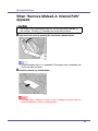
When “Remove Misfeed A: Internal Path” Appears .........................................96
When “Remove Misfeed B: Fusing Unit” Appears ...........................................99
When “Remove Misfeed Y: Paper Tray” Appears...........................................102
When “Remove Misfeed Z: Duplex Unit” Appears .........................................104
Appendix
Moving and Transporting the Printer...............................................................106
Moving the Printer ..................................................................................................106
Transporting the Printer ......................................................................................... 107
Consumables .....................................................................................................108
Toner Cartridge ......................................................................................................108
Waste Toner Bottle ................................................................................................109
Photo Conductor Unit.............................................................................................109
Intermediate Transfer Unit (Transfer Unit) ............................................................. 109
Specifications.....................................................................................................111
Mainframe ..............................................................................................................111
Options...................................................................................................................113
2
Read This First
Trademarks
Microsoft, Windows and Windows NT are registered trademarks of Microsoft
Corporation in the United States and/or other countries.
IPS-PRINT Printer Language Emulation Copyright© 1999-2000 Oak Technology, Inc., All rights reserved.
Bluetooth® is a registered trademark of the Bluetooth SIG, Inc. worldwide.
Other product names used herein are for identification purposes only and might
be trademarks of their respective companies. We disclaim any and all rights to
those marks.
The proper names of the Windows operating systems are as follows:
• Microsoft® Windows® 95 operating system
• Microsoft® Windows® 98 operating system
• Microsoft® Windows® Millennium Edition (Windows Me)
• The product names of Windows® 2000 are as follows:
Microsoft® Windows® 2000 Advanced Server
Microsoft® Windows® 2000 Server
Microsoft® Windows® 2000 Professional
• The product names of Windows® XP are as follows:
Microsoft® Windows® XP Professional
Microsoft® Windows® XP Home Edition
• The product names of Windows ServerTM 2003 are as follows:
Microsoft® Windows ServerTM 2003 Standard Edition
Microsoft® Windows ServerTM 2003 Enterprise Edition
Microsoft® Windows ServerTM 2003 Web Edition
• The product names of Windows NT® 4.0 are as follows:
Microsoft® Windows NT® Server 4.0
Microsoft® Windows NT® Workstation 4.0
G1398504_1.00
Copyright © 2005
3
Read This First
How to Read This Manual
The following set of symbols is used in this manual.
This symbol indicates a potentially hazardous situation that might result in death
or serious injury when you misuse the machine without following the instructions
under this symbol. Be sure to read the instructions, all of which are described in
the Safety Information section.
This symbol indicates a potentially hazardous situation that might result in minor
or moderate injury or property damage that does not involve personal injury
when you misuse the machine without following the instructions under this symbol. Be sure to read the instructions, all of which are described in the Safety Information section.
* The statements above are notes for your safety.
If this instruction is not followed, paper might be misfed, originals might be damaged, or data might be lost. Be sure to read this.
This symbol indicates information or preparations required prior to operating.
This symbol indicates precautions for operation, or actions to take after abnormal
operation.
This symbol indicates numerical limits, functions that cannot be used together,
or conditions in which a particular function cannot be used.
This symbol indicates a reference.
[]
Keys that appear on the machine's display.
Keys and buttons that appear on the computer's display.
{}
Keys built into the machine's control panel.
Keys on the computer's keyboard.
4
Paper and Other Media
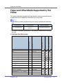
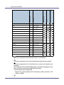
Paper and Other Media Supported by This
Printer
This section describes the paper size, feed direction, and the maximum amount
of paper that can be loaded into each paper tray in this printer.
❒ The following symbols and terminology are used to represent the feed direction.
In this manual
On the display
K ↑ (Feed direction)
A4 (210 x 297)
8 1/2 x 11
Paper feed direction
Short-edge feed direction
❒ Be careful of the paper feed direction. The direction is determined for each paper size.
210 × 297
B5
K
182 × 257
A5
K
148 × 210
A6
K
105 × 148
Legal (LG, 81/2 × 14 inches)
K
216 × 356
Letter (LT, 81/2 × 11 inches)
K
216 × 279
51/2 × 81/2 inches
K
140 × 216
Executive (Exec., 71/4 × 101/2 inches) K
184 × 276
Folio (81/4 × 13 inches)
K
210 × 330
Foolscap (F4, 81/2 × 13 inches)
K
216 × 330
F/GL (8 × 13 inches)
K
203 × 330
Com#10 Env (4 1/8 × 9 1/2 inches)
K
104.8 × 241.3
C5 Env (6.38 × 9.02 inches)
K
162 × 229
G1398504_1.00
Paper Feed Unit (Tray 2/3)
K
Tray 1
Size (mm)
A4
Bypass Tray
Feed direction
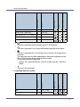
❖ Input Paper Sizes (Metric version)
Copyright © 2005
5
114 × 162
DL Env (4.33 × 8.66 inches)
K
110 × 220
Monarch Env (3 7/8 × 7 1/2 inches)
K
98.4 × 190.5
Custom Size
-
-
16K (7.68 × 101/2 inches)
K
195 × 267
Paper Feed Unit (Tray 2/3)
K
Tray 1
Size (mm)
C6 Env (4.49 × 6.38 inches)
Bypass Tray
Feed direction
Paper and Other Media
•
The size is supported and the printer selects it automatically.
•
The size is supported, but it should be selected using the control panel.
•
The size is supported, but it should be set as a custom size using the control panel.
The supported size may differ depending on the printer language you use.
Set as a custom size setting using the control panel.
The following sizes are supported:
• Bypass Tray: approximately 90 - 216 mm in width, and 148 - 356 mm in
length.
•
The size is not supported.
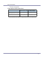
8.26” × 11.69”
B5
K
7.17” × 10.12”
Paper Feed Unit (Tray 2/3)
K
Tray 1
Size (inch)
A4
Bypass Tray
Feed direction
❖ Input Paper Sizes (Inch version)
6
5.83” × 8.26”
A6
K
4.13” × 5.63”
Legal (LG)
K
81/2” × 14”
Letter (LT)
K
81/2” × 11”
5 1/2 × 8 1/2 inches
K
51/2” × 81/2”
Executive (Exec.)
K
71/4” × 101/2”
Folio
K
81/4” × 13”
Foolscap F4
K
81/2” × 13”
F/GL
K
8” × 13”
Com#10 Env
K
4 1/8” × 9 1/2”
C5 Env
K
6.38” × 9.02”
C6 Env
K
4.49” × 6.38”
DL Env
K
4.33” × 8.66”
Monarch Env
K
3 7/8” × 7 1/2”
Custom Size
-
-
16K
K
7.68” × 101/2”
Paper Feed Unit (Tray 2/3)
K
Tray 1
Size (inch)
A5
Bypass Tray
Feed direction
Paper and Other Media
•
The size is supported and the printer selects it automatically.
•
The size is supported, but it should be selected using the control panel.
•
The size is supported, but it should be set as a custom size using the control panel.
The supported size may differ depending on the printer language you use.
Set as a custom size setting using the control panel.
The following sizes are supported:
• Bypass Tray: approximately 3.55 - 8.50 inches in width, and 5.83 - 14.01
inches in length.
•
7
Paper and Other Media
The size is not supported.
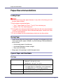
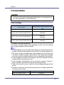
❖ Paper weight and number of sheets to be set
Supported paper weight
Tray 1
Paper Feed Unit (Tray 2, Tray 3)
Bypass Tray
Maximum number of
sheets (plain paper)
60.2 - 104.7 g/m2 (16 - 28
lb.)
530 (80 g/m2, 20 lb.)
60.2 - 199 g/m2 (16 - 53
lb.)
100 (80 g/m2, 20 lb.)
Check that the top of the stack is not higher than the limit mark inside the tray.
8
Paper and Other Media
Paper Recommendations
Loading Paper
❒ Do not use ink-jet printer paper because it may stick to the fusing unit and
cause a paper misfeed.
❒ Set the paper as described below
• Tray 1, Paper Feed Unit (Tray 2, Tray 3): Print side facing up
• Bypass Tray: Print side facing down
❒ Print quality cannot be guaranteed if paper other than the ones recommended
is used. For more information about recommended paper, contact your sales
or service representative.
❒ Do not use paper that has already been printed onto by other printers.
Storing Paper
• Paper should always be stored properly. Improperly stored paper might result
in poor print quality, paper misfeeds, or printer damage. Recommendations
are as follows:
• Avoid storing paper in humid areas.
• Avoid exposing paper to direct sunlight.
• Store on a flat surface.
• Keep paper in the package in which the paper came.
Types of Paper and Other Media
Plain Paper
Paper thickness
Printer setup
Printer driver setup
60.2 - 104.7 g/m2 (16 - 28 lb.)
•
[Thin]: 60.2 - 90.2 g/m2 (16 - 24 lb.)
•
[Normal]: 90.2 - 104.7 g/m2 (24 - 28 lb.)
Make the following two settings using the control panel:
•
Press [Paper Input] menu, [Paper Type], and then [Plain Paper].
•
Press [Maintenance] menu, and then [Thin] or [Normal].
Click [Plain] or [Plain & Recycled] in the [Type:] list.
Enabled paper feeding tray Any input tray can be used.
9
Paper and Other Media
Number of sheets that can
be set
•
Tray 1: 530
•
Tray 2, Tray 3 (Paper Feed Unit Type 3000): 530
•
Bypass Tray: 100
❒ Make sure paper is not stacked higher than the upper limit
mark (T) inside the tray. Make sure paper is not stacked higher
than the paper guides inside the bypass tray.
Both-side printing
Possible
Thick Paper
Paper thickness
105 - 199 g/m2 (28 - 53 lb.)
•
[Thick Paper 1]: 105 - 165 g/m2 (28 - 44 lb.)
•
[Thick Paper 2]: 165 - 199 g/m2 (44 - 53 lb.)
Printer setup
Press [Paper Input] menu, [Paper Type] and then [Thick Paper 1] or
[Thick Paper 2] on the control panel.
Printer driver setup
Click [Thick1] or [Thick2] in the [Type:] list.
Enabled paper feeding tray Bypass Tray
•
[Thick Paper 1]: 30
•
[Thick Paper 2]: 10
❒
Make sure paper is not stacked higher than the paper guides
inside the bypass tray.
Both-side printing
Not possible
Additional cautions
•
Print speed is slightly slower than when using plain paper.
Adhesive labels
Printer setup
Press [Paper Input] menu, [Paper Type], and then [Labels] on the
control panel.
Printer driver setup
Click [Labels] in the [Type:] list.
Enabled paper feeding tray Bypass Tray: 50
❒ Make sure paper is not stacked higher than the paper guides
inside the bypass tray.
Both-sided printing
Not possible
Additional cautions
Print speed is slightly slower compared to plain paper.
OHP transparencies
Printer setup
Press [Paper Input] menu, [Paper Type], and then [Transparency] on
the control panel.
10
Paper and Other Media
Printer driver setup
Click [Transparency] in the [Type:] list.
Enabled paper feeding tray Bypass Tray
Number of sheets that can
be set
Bypass Tray: 50
❒ Make sure paper is not stacked higher than the paper guides
inside the bypass tray.
Both-sided printing
Not possible
Additional cautions
•
Print speed for OHP transparencies is slower than for plain paper.
•
Due to switching modes, the machine will be on standby for
thirty or forty seconds after the job was received.
•
We recommend that you use a 4000 ANSI lumen or brighter
overhead projector to project OHP transparencies.
Glossy Paper
Printer setup
Press [Paper Input] menu, [Paper Type], and then [Glossy Paper] on
the control panel.
Printer driver setup
Click [Glossy] in the [Type:] list.
Enabled paper feeding tray Bypass Tray: 50
❒ Make sure paper is not stacked higher than the paper guides
inside the bypass tray.
Both-sided printing
Not possible
Additional cautions
Print speed is slightly slower compared to plain paper.
Envelopes
Printer setup
Press [Paper Input] menu, [Paper Type], and then [Thick Paper 1] or
[Thick Paper 2] on the control panel.
Printer driver setup
Click [Thick1] or [Thick2]in the [Type:] list.
Enabled paper feeding tray Bypass Tray: 10
❒ Make sure paper is not stacked higher than the paper guides
inside the bypass tray.
Both-sided printing
Not possible
11
Paper and Other Media
Additional cautions
•
Check the print side is facing down.
•
Check there is no air in the envelopes before loading.
•
For better print quality, we recommend the right, left, top, and
bottom print margins to be at least 15 mm 0.6 inch.
•
Load only one size and type of envelope at a time.
•
Before loading envelopes, flatten their leading edges (the edge
going into the printer) by running a pencil or ruler across them.
•
Some kinds of envelope might cause misfeeds, wrinkles or
print poorly.
•
Print quality on envelopes may be uneven if parts of an envelope have differing thicknesses. Print one or two envelopes to
check print quality.
•
Use flat envelopes with no curl. If they have a curl, flatten them.
•
Use completely flat envelopes that contain no air inside.
•
Do not print on both sides of envelopes.
Paper not supported by this printer
Avoid using the following paper as they are not supported by this printer.
• Paper meant for an ink-jet printer
• Bent, folded, or creased paper
• Curled or twisted paper
• Torn paper
• Wrinkled paper
• Damp paper
• Paper that is dry enough to emit static electricity
• Paper that has already been printed onto, except a preprinted letterhead.
Malfunctions are especially likely when using paper printed on by other than
a laser printer (e.g. monochrome and color copiers, ink-jet printers, etc.)
• Special paper, such as thermal paper, aluminum foil, carbon paper and conductive paper
• Paper whose weight is heavier or lighter than the limitation
• Paper with windows, holes, perforations, cutouts, or embossing
• Adhesive label paper on which glue or base paper is exposed
• Paper with clips or staples
• Do not use the following envelopes:
• Envelopes with multiple flaps
• Envelopes with a peel-off adhesive strip
• Envelopes with windows or clasps
12
Paper and Other Media
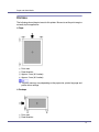
Print Area
The following shows the print area for this printer. Be sure to set the print margins
correctly by the application.
❖ Paper
A
B
C
D
Print area
Feed direction
Approx. 5 mm (0.2 inches)
Approx. 5 mm (0.2 inches)
❒ The print area may vary depending on the paper size, printer language and
printer driver settings.
❖ Envelope
A
B
Print area
Feed direction
13
Paper and Other Media
C
D
Approx. 5 mm (0.2 inches)
Approx. 5 mm (0.2 inches)
❒ The print area may vary depending on the paper size, printer language and
printer driver settings.
14
Paper and Other Media
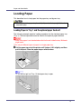
Loading Paper
This describes how to load paper into the paper tray and bypass tray.
• Do not pull out the paper tray forcefully. If you do, the tray might fall and
cause an injury.
Loading Paper in Tray 1 and the optional paper feed unit
The following example explains loading procedure for the standard paper tray
(Tray 1). The same procedure can be used for the optional paper feed unit.
❒ Make sure paper is not stacked above the limit mark inside the tray. Misfeeds
might occur.
❒ Do not put different types of paper in a single paper tray.
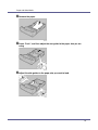
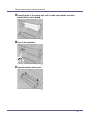
A Pull the paper tray out of the printer until it stops. Lift it slightly, and then
pull it fully out. Place the paper tray on a flat surface.
❒ You can not pull out Tray 1 if the bypass tray is open.
15
Paper and Other Media
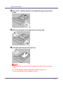
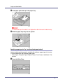
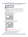
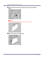
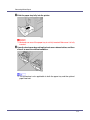
B Press “Push”, and then adjust the rear guide to the paper size you want
to load.
C Adjust the side guides to the paper size you want to load.
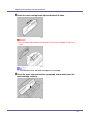
D Load paper print side up in the paper tray.
❒ Make sure the top of the stack is not higher than the limit mark inside the
tray.
❒ To avoid misfeeds, set the side guides to the exact paper size.
❒ Do not load different kinds of paper in the tray.
16
Paper and Other Media
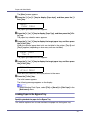
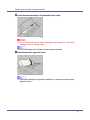
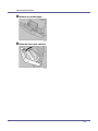
E Slide the paper tray fully into the printer.
❒ Misfeeds can occur if the paper tray is not fully inserted. Make sure it is fully
inserted.
Changing paper size of the paper tray
A Pull the paper tray out of the printer until it stops. Lift it slightly, and then
pull it fully out. Place the paper tray on a flat surface.
❒ You can not pull out Tray 1 if the bypass tray is open.
17
Paper and Other Media
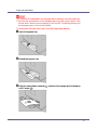
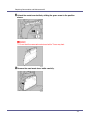
B Remove the paper.
C Press “Push”, and then adjust the rear guide to the paper size you are
using.
D Adjust the side guides to the paper size you want to load.
18
Paper and Other Media
E Load paper print side up in the paper tray.
❒ Check the top of the stack is not higher than the limit mark inside the tray.
F Slide the paper tray fully into the printer.
Specifying a paper type for Tray 1 and the optional paper feed unit
Improve printer performance by selecting the optimum paper type for the tray.
You can select from the following paper types:
• Plain Paper, Recycled Paper, Special Paper, Color Paper, Letterhead, Preprinted
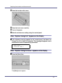
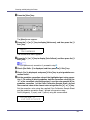
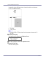
A Press the {Menu} key.
19
Paper and Other Media
The [Menu] screen appears.
B Press the {U} or {T} key to display [Paper Input], and then press the {#
Enter} key.
Menu:
Paper Input
The paper type selection menu appears.
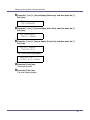
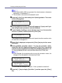
C Press the {U} or {T} key to display [Paper Type], and then press the {# Enter} key.
The paper tray selection menu appears.
D Press the {U} or {T} key to display the target paper tray, and then press
the {# Enter} key.
When the optional paper feed units are installed in the printer, [Tray 2] and
[Tray 3] appears (depending on how many units are installed).
Paper Type:
Tray 2
The paper type selection menu appears.
E Press the {U} or {T} key to display the target paper tray, and then press
the {# Enter} key.
Tray 2:
*Plain Paper
After about two seconds, the display returns to the menu.
F Press the {Online} key.
The initial screen appears.
The following message appears on the display:
❒ When selecting Plain Paper, select [Thin] or [Normal] for [Plain Paper] in the
[Maintenance] menu.
Loading Paper in the Bypass Tray
Specifying standard size paper for the Bypass Tray
This section explains how to load standard size paper into the bypass tray.
20
Paper and Other Media
❒ To avoid multi-sheet feeds, fan the paper before loading it onto the paper tray.
❒ Set the size and direction of the loaded paper using the control panel or the
printer driver. Make sure the settings do not conflict. Conflicting settings can
cause paper jams or loss of print quality.
❒ Load paper print side down and in the short-edge feed direction.
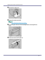
A Open the bypass tray.
B Extend the bypass tray.
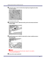
C Slide the side guides outward (
), and then insert paper print side down
until it stops ( ).
21
Paper and Other Media
D Adjust the side guides to the paper width.
❒ Check the top of the stack is not higher than the limit mark inside the tray.
❒ To avoid multi-sheet feeds, fan the paper before loading it onto the paper
tray.
E Set the paper size using the control panel. Press the {Menu} key.
The [Menu]screen appears.
F Press the {U} or {T} key to display [Paper Input], and then press the {#
Enter} key.
Menu:
Paper Input
The paper selection menu appears.
G Check that [Bypass Size] appears, and then press the {# Enter} key
The paper size selection menu appears.
22
Paper and Other Media
H Press the {U} or {T} key to display the size and orientation of the paper
in the bypass tray.
Bypass Size:
*8 x 13
After about two seconds, the display returns to the menu.
I Press the {Online} key.
The initial screen appears.
❒ To load thick paper, OHP transparencies, or envelopes, make settings for
thick paper or OHP transparencies using the control panel and printer driver.
❒ The number of pages that can be loaded in the bypass tray differs depending on paper type. Make sure paper is not stacked above the paper guides
inside the bypass tray.
For details about control panel settings for custom size paper or special paper, see p.23 “Specifying custom size paper for the Bypass Tray”.
To select custom size paper (148 - 356 mm in length, 90 - 216 mm in
width), see p.23 “Specifying custom size paper for the Bypass Tray”.
For control panel settings when using thick paper, OHP transparencies, or
post cards, see p.25 “Specifying a paper type for the Bypass Tray”.
Specifying custom size paper for the Bypass Tray
❒ When loading custom size or special paper, specify the paper size using the
control panel and printer driver.
❒ Paper sizes between 148 - 356 in length and 90 - 216 mm in width can be
loaded in the bypass tray.
❒ The custom paper size selected using the printer driver overrides that selected using the control panel. Do not configure settings using the control panel if
you have already made settings using the printer driver. However, when printing with a printer driver other than the RPCS printer driver, you must configure
the settings using the control panel.
❒ You cannot print on custom size paper with an application that does not support the custom size setting.
23
Paper and Other Media
A Press the {Menu} key.
The [Menu]screen appears.
B Press the {U} or {T} key to display [Paper Input], and then press the {#
Enter} key.
Menu:
Paper Input
The paper selection menu appears.
C Check [Bypass Size] appears, and then press the {# Enter} key.
The paper size selection menu appears.
D Press the {U} or {T} key to display [Custom Size], and then press the {#
Enter} key.
E Press the {U} or {T} key to set the horizontal value, and then press the
{# Enter} key.
Custom Size:
Horiz.
8.50”
By pressing the key, the value increases or decreases by 0.01 inch. By pressing and holding the key, the value varies by 1 inch.
F Press the {U} or {T} key to set the vertical value, and then press the {#
Enter} key.
Custom Size:
Vert.
11.00”
After about two seconds, the display returns to the menu.
G Press the {Online} key.
The initial screen appears.
24
Paper and Other Media
For details about the printer driver, see the printer driver Help.
Specifying a paper type for the Bypass Tray
By selecting the paper type you want to load, the printer performs better. You can
select from the following paper types:
• Plain Paper, Recycled Paper, Special Paper, Color Paper, Letterhead, Preprinted, Labels (adhesive label paper) , Bond Paper, Cardstock, Transparency (OHP transparency), Thick Paper 1, Thick Paper 2, Glossy Paper
❒ Be sure to select the paper type when you load labels, thick paper, or OHP
transparencies in the bypass tray.
❒ The paper type selected using the printer driver overrides that selected using
the control panel.
A Press the {Menu} key.
The [Menu]screen appears.
B Press the {U} or {T} key to display [Paper Input], and then press the {#
Enter} key.
Menu:
Paper Input
The paper selection menu appears.
C Press the {U} or {T} key to display [Paper Type], and then press the {# Enter} key.
The paper tray selection menu appears.
D Press the {U} or {T} key to display [Bypass Tray], and then press the {#
Enter} key.
The paper type selection menu appears.
25
Paper and Other Media
E Press the {U} or {T} key to display the loaded paper type, and then
press the {# Enter} key.
Bypass Tray:
Recycled Paper
After about two seconds, the display returns to the menu.
F Press the {Online} key.
The initial screen appears.
The following message appears on the display:
❒ When selecting Plain Paper, select [Thin] or [Normal] for [Plain Paper] in the
[Maintenance] menu.
❒ The following paper types cannot be printed on both sides:
• Special Paper, Labels (adhesive label paper), Cardstock, Transparency
(OHP transparency), Thick Paper 2 (165 - 199 g/m2), Thin Paper,
Plain:Dup.Back (reverse side of plain paper), Thick1:Dup.Back (reverse
side of thick paper)
Switching between Paper Trays
When paper of the same size is loaded in both the standard tray and the paper
feed unit (option), and when [Auto Tray Select] is set with the printer driver, paper
will be fed from the standard tray when you start printing. To print on paper loaded in the paper feed unit, switch the tray to be used to the paper feed unit using
[Tray Priority] in the [Paper Input] menu.
A Press the {Menu} key.
The [Menu]screen appears.
26
Paper and Other Media
B Press the {U} or {T} key to display [Paper Input], and then press the {#
Enter} key.
Menu:
Paper Input
The paper selection menu appears.
C Press the {U} or {T} key to display [Tray Priority], and then press the {#
Enter} key.
The paper tray selection menu appears.
D Press the {U} or {T} key to select the tray type you want to use, and
then press the {# Enter} key.
The following message appears on the display:
Tray Priority:
*Tray 2
E Press the {Online} key.
The initial screen appears.
27
Replacing Consumables and Maintenance Kit
Replacing the Toner Cartridge
• Do not incinerate spilled toner or used toner. Toner dust is flammable
and might ignite when exposed to an open flame.
• Disposal should take place at an authorized dealer or an appropriate
collection site.
• If you dispose of the used toner cartridges yourself, dispose of them
according to local regulations.
• Do not store toner, used toner, or toner containers in a place with an
open flame. The toner might ignite and cause burns or a fire.
• Keep toner (used or unused) and the toner cartridge out of reach of children.
• If toner or used toner is inhaled, gargle with plenty of water and move into
a fresh air environment. Consult a doctor if necessary.
• If your skin comes into contact with toner or used toner, wash the affected
area thoroughly with soap and water.
• If toner or used toner gets into your eyes, flush immediately with large
amounts of water. Consult a doctor if necessary.
• If toner or used toner is swallowed, dilute by drinking a large amount of water. Consult a doctor if necessary.
• Avoid getting toner on your clothes or skin when removing a paper jam or
replacing toner. If your skin comes into contact with toner, wash the affected
area thoroughly with soap and water.
• If toner gets on your clothing, wash with cold water. Hot water will set the
toner into the fabric and may make removing the stain impossible.
❒ When handling toner cartridges, never stand them up on either end or position
them upside down.
❒ Store toner cartridges in a cool dark place.
❒ Actual printable numbers vary depending on image volume and density, number of pages printed at a time, paper type and size, and environmental conditions such as temperature and humidity. Toner quality degrades over time.
You may have to replace the toner cartridge prematurely. We recommend you
prepare a new toner cartridge beforehand.
The color of the lit LED indicates the toner status for each color. A red light indicates the toner cartridge must be replaced.
G1398504_1.00
Copyright © 2005
28
Replacing Consumables and Maintenance Kit
Replace the toner cartridge if the following message appears on the display:
Add Toner
XXX/XXX
❒ A combination of one to four colors, yellow, magenta, cyan, black, appears in
“XXX”.
❒ If cyan, magenta, or yellow toner runs out, you can print in black and white
using black toner. Change the color mode setting to “Black and White” using
the printer driver.
❒ If black toner runs out, you cannot print in black and white or color until the
black toner cartridge is replaced.
A Open the upper left cover of the printer.
B Remove the toner cartridge you want to replace.
❒ Do not shake the removed toner cartridge. Remaining toner may leak.
❒ All four cartridges are removed using the same procedure.
❒ The illustration uses the yellow cartridge as an example.
C Take a new toner cartridge out of its package.
29
Replacing Consumables and Maintenance Kit
D Shake the toner cartridge from side to side about 10 times.
❒ Do not open the shutter at the bottom of the toner cartridge. Toner may
leak.
❒ The illustration uses the black cartridge as an example.
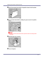
E Check the toner color and location correspond, and carefully insert the
toner cartridge vertically.
30
Replacing Consumables and Maintenance Kit
F Insert the toner cartridge in the direction of the arrow.
❒ Do not install and remove toner cartridges unless necessary. Excessive
handling results in toner leakage.
❒ All four cartridges are installed using the same procedure.
G Close the printer's upper left cover.
❒ If the toner cartridge is not properly installed, you cannot close the printer's
upper left cover.
31
Replacing Consumables and Maintenance Kit
Replacing the Waste Toner Bottle
• Do not incinerate spilled toner or used toner. Toner dust is flammable
and might ignite when exposed to an open flame. Disposal should
take place at an authorized dealer or an appropriate collection site. If
you dispose of the used toner containers yourself, dispose of them
according to local regulations.
• Keep toner (used or unused) and the toner cartridge out of reach of children.
• Do not put an object on the right cover when it is open.
Replace the waste toner bottle when the following message appears on the display:
Replace Used
Toner Bottle
A Turn off the power, and then unplug the power cable.
B Open the right cover.
C Take a new waste toner bottle out of its the bag.
32
Replacing Consumables and Maintenance Kit
D Unlock the waste toner bottle by sliding the green arrow to the position
shown.
❒ Do not lock the removed waste toner bottle. Toner may leak.
E Remove the used waste toner bottle carefully.
33
Replacing Consumables and Maintenance Kit
F Place the new waste toner bottle in the position shown in the illustration.
G Lock the waste toner bottle by sliding the green arrow to the position
shown.
❒ Be sure to lock the waste toner bottle to prevent toner from leaking inside
the printer.
H Close the right cover carefully.
I Turn on the power.
34
Replacing Consumables and Maintenance Kit
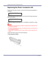
Replacing the Photo Conductor Unit
Replace the black photo conductor unit when the following message appears on
the display:
Replace Black
PCU
Replace the three color photo conductor units when the following message appears on the display:
Replace Color
PCU
Color photo conductor units (yellow, cyan, and magenta) are supplied as a single
item.
❒ Exposure to light reduces photo conductor unit performance. Replace the unit
as quickly as possible.
❒ Do not pull out the photo conductor unit with force or haste, it may fall and you
may damage the machine.
❒ Take care that nothing comes into contact with the surface of the photo conductor.
Check the contents of the box for the following items:
❖ Photo Conductor Unit Black
35
Replacing Consumables and Maintenance Kit
❖ Photo Conductor Unit Color
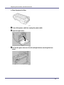
A Turn off the power, and then unplug the power cable.
B Open the right cover.
C Pull out the green levers on the left and right that are securing the inner
cover.
36
Replacing Consumables and Maintenance Kit
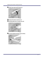
D Lift the inner cover until it stays up.
E Remove the photo conductor unit.
F Pinch the green lever to unlock the unit.
G Pull out the photo conductor unit carefully.
37
Replacing Consumables and Maintenance Kit
H Pinch the green lever to unlock the unit.
I Pull out the photo conductor unit carefully until it stops.
J Pinch the green part to release the unit.
K Pull out the photo conductor unit carefully.
❒ Be sure to hold the unit with both hands, and pull it out carefully.
L Take out the new photo conductor unit.
38
Replacing Consumables and Maintenance Kit
M Remove the cap attached to the photo conductor unit.
❒ The cap is no longer needed and can be disposed of.
N Remove the tape from around Photo Conductor Unit by peeling it downward, and then remove the unit's top cover.
❒ Do not remove the cover attached to the bottom of the photo conductor unit
yet.
39
Replacing Consumables and Maintenance Kit
❒ After you take the new Photo Conductor Unit out of the bag, quickly install
it.
O Check the locations for each Photo Conductor Unit.
A
B
Photo Conductor Unit (Black)
Photo Conductor Unit (Color)
P Align the green arrow at the tip of the photo conductor unit with the rail
inside the printer.
❒ Make sure the green arrow fits securely to the rail before proceeding to the
next step.
❒ If you do not securely attach the green arrow of the photo conductor unit to
the rail, you may damage the photo conductor unit.
40
Replacing Consumables and Maintenance Kit
❖ Photo Conductor Unit Black
❖ Photo Conductor Unit Color
Q Push the front of the photo conductor unit carefully in sliding the unit
from its cover until it stops.
❖ Photo Conductor Unit Black
41
Replacing Consumables and Maintenance Kit
❖ Photo Conductor Unit Color
❒ If the photo conductor unit is not correctly installed, print quality will be lost.
For example, certain colors may not print.
R Lower the inner cover slowly.
S Push the left and right edge of the inner cover to secure it.
42
Replacing Consumables and Maintenance Kit
T Close the right cover carefully.
U Plug in the power cable, and then turn on the power.
The printer starts calibration. Wait until it stops. The following message appears on the display:
Calibrating...
Wait until [Ready] appears on the display panel.
❒ Do not turn off the power during calibration. Doing so results in malfunction.
43
Replacing Consumables and Maintenance Kit
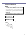
Replacing the Fusing Unit
• The inside of this machine gets very hot. Do not touch parts labelled
“v”(hot surface). Touching “v” labelled parts (hot surface) could result in
burns.
• The fusing unit gets very hot. When installing a new fusing unit, turn off the
printer and wait about 30 minutes. Then you can install the new fusing unit.
Handling the unit before it has fully cooled down (30 mins) could result in
burns.
• Do not pull out the fusing unit forcefully. Doing so may cause the unit to fall
and result in injury.
• Only the handle of the fusing unit is safe to touch. Touching other areas may
result in burns.
Replace the fusing unit when the following message appears on the display:
Replace Fusing
Unit soon
or
Replace
Fusing Unit
Check the contents of the box for the following items:
❖ Fusing Unit
44
Replacing Consumables and Maintenance Kit
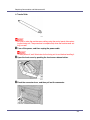
❖ Transfer Roller
❒ Be sure to make the maintenance setting using the control panel after replacing the fusing unit. The procedure is complete only when the maintenance setting is made.
A Turn off the power, and then unplug the power cable.
❒ After power off, wait 30 minutes for the fusing unit to cool before handling it.
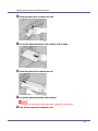
B Open the front cover by pushing the front cover release button.
C Pinch the connector lever, and then pull out the connector.
45
Replacing Consumables and Maintenance Kit
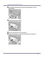
D Push the green release buttons on the left and right outwards to unlock
the fusing unit.
E Remove the fusing unit carefully.
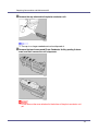
F Take the new fusing unit from out from its box.
G Place the unit as shown, and then carefully insert the new fusing unit.
46
Replacing Consumables and Maintenance Kit
H Carefully push in the fusing unit until it clicks into position, and then
check that the unit is locked.
I Push in the connector.
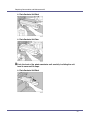
J Open the transfer roller cover.
47
Replacing Consumables and Maintenance Kit
K Turn the green part in the direction of the arrow, and then remove the
transfer roller.
L Take out the new transfer roller.
❒ Do not touch the roller part.
M Hold the green part as shown, and then insert the transfer roller into the
printer.
❒ The end with the longer shaft must be to the left.
48
Replacing Consumables and Maintenance Kit
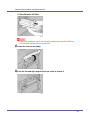
N Close the transfer roller cover.
O Close the front cover carefully.
P Turn on the power.
Q Make the maintenance setting using the control panel.
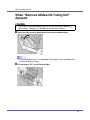
When “Replace Fusing Unit” Appears on the Display
A If the following message appears on the control panel, hold down the
{Escape} key for at least five seconds. The message disappears and a
maintenance reset is automatically performed.
Replace
Fusing Unit
When “Replace Fusing Unit soon” Appears on the Display
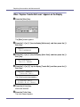
A Press the {Menu} key.
The [Menu]screen appears.
49
Replacing Consumables and Maintenance Kit
B Press the {U} or {T} key to display [Maintenance], and then press the {#
Enter} key.
Menu:
Maintenance
C Press the {U} or {T} key to display [Maint. Reset], and then press the {#
Enter} key.
Maintenance:
Maint. Reset
D Press the {U} or {T} key to display [Fusing Unit], and then press the {#
Enter} key.
Maint. Reset:
Fusing Unit
The following message appears:
Fusing Unit
Press # to reset
E Press the {# Enter} key.
Wait a few seconds.
F Press the {Online} key.
The initial screen appears.
50
Replacing Consumables and Maintenance Kit
Replacing the Intermediate Transfer Unit
• The inside of this machine gets very hot. Do not touch parts labelled “v”
(hot surface). Touching “v” labelled parts could result in burns.
Replace the transfer belt when the following message appears on the display:
Replace Transfer
Belt soon
or
Replace
Transfer Belt
Check the contents of the box for the following items:
❖ Transfer Belt
❒ Be sure to make the maintenance setting using the control panel after replacing the transfer belt. The procedure is complete only when the maintenance
setting is made.
A Turn off the power, and then unplug the power cable.
51
Replacing Consumables and Maintenance Kit
B Open printer's right cover.
C Remove the waste toner bottle.
See p.32 “Replacing the Waste Toner Bottle”.
D Pull out the green levers on the left and right that are securing the inner
cover.
E Lift the inner cover until it stays up.
52
Replacing Consumables and Maintenance Kit
F Unlock the waste toner bottle by sliding the green arrow to the position
shown.
❒ Do not lock the removed waste toner bottle. Toner may leak.
G Remove the waste toner bottle carefully.
53
Replacing Consumables and Maintenance Kit
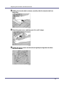
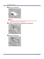
H Loosen the green screws on the left and right by turning them the direction of the arrows.
Do not remove the screws.
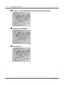
I Pinch the both screws, and then carefully pull out the transfer belt slowly until it stops.
J Raise the green cover, hold the transfer belt as shown, and then remove
the transfer belt.
❒ Be sure to hold the unit with both hands, and pull it out carefully.
❒ Do not touch the belt part.
K Take out the new transfer belt.
54
Replacing Consumables and Maintenance Kit
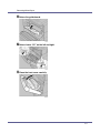
L Holding the transfer belt as shown, carefully slide the transfer belt into
the printer.
M Close the green cover, and then push it in until it stops.
N Tighten the green screws on the left and right by turning them the direction of the arrows.
55
Replacing Consumables and Maintenance Kit
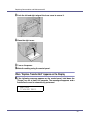
O Place the waste toner bottle in the position shown in the illustration.
P Lock the waste toner bottle by sliding the green arrow to the position
shown.
❒ Be sure to lock the waste toner bottle to prevent toner from leaking inside
the printer.
Q Lower the inner cover slowly.
56
Replacing Consumables and Maintenance Kit
R Push the left and right edge of the inner cover to secure it.
S Close the right cover.
T Turn on the power.
U Make the setting using the control panel.
When “Replace Transfer Belt” Appears on the Display
A If the following message appears on the control panel, hold down the
{Escape} key for at least five seconds. The message disappears and a
maintenance reset is automatically performed.
Replace
Transfer Belt
57
Replacing Consumables and Maintenance Kit
When “Replace Transfer Belt soon” Appears on the Display
A Press the {Menu} key.
The [Menu] screen appears.
B Press the {U} or {T} key to display [Maintenance], and then press the {#
Enter} key.
Menu:
Maintenance
C Press the {U} or {T} key to display [Maint. Reset], and then press the {#
Enter} key.
Maintenance:
Maint. Reset
D Press the {U} or {T} key to display [Transfer Belt], and then press the {#
Enter} key.
Maint. Reset:
Transfer Belt
The following message appears:
Transfer Belt
Press # to reset
E Press the {# Enter} key.
Wait a few seconds.
F Press the {Online} key.
The initial screen appears.
58
Cleaning and Adjusting the Printer
Cautions to Take When Cleaning
• Do not remove any covers or screws other than those specified in this
manual. Some parts of the machine are at a high voltage and could
give you an electric shock. Also, if the machine has laser systems, direct (or indirect) reflected eye contact with the laser beam may cause
serious eye damage. When the machine needs to be checked, adjusted, or repaired, contact your service representative.
• Do not take apart or attempt any modifications to this machine. There
is a risk of fire, electric shock, explosion or loss of sight. If the machine has laser systems, there is a risk of serious eye damage.
• When removing misfed paper, do not touch the fusing unit because it could
be very hot.
Clean the printer periodically to maintain fine printing.
Dry wipe the exterior with a soft cloth. If dry wiping is not enough, wipe with a
soft, wet cloth that is wrung out well. If you still cannot remove the stain or grime,
use a neutral detergent, and then wipe over with a well-wrung wet cloth, dry
wipe, and let it dry.
❒ To avoid deformation, discoloration, or cracking, do not use volatile chemicals, such as benzine and thinner, or spray insecticide on the printer.
❒ If there is dust or grime inside the printer, wipe with a clean, dry cloth.
❒ You must disconnect the plug from the wall outlet at least once a year. Clean
away any dust and grime from the plug and outlet before reconnecting. Accumulated dust and grime pose a fire hazard.
G1398504_1.00
Copyright © 2005
59
Cleaning and Adjusting the Printer
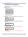
Adjusting the Color Registration
If documents show color degradation after the printer is moved, perform automatic color adjustment.
A Press the {Menu} key.
The [Menu] screen appears.
B Press the {U} or {T} key to display [Maintenance], and then press the {#
Enter} key.
Menu:
Maintenance
The maintenance menu appears.
C Press the {U} or {T} key to display [Color Regist.], and then press the {#
Enter} key.
The check message appears.
Press #
to adjust
D Press the {# Enter} key.
Automatic color adjustment begins, and the following message appears.
Adjusting...
❒ To avoid malfunction, do not turn off the power while [Adjusting... ] appears
on the display.
60
Cleaning and Adjusting the Printer
Automatic color adjustment takes about 30 seconds. A confirmation message
appears when complete.
Completed
E Press the {Escape} key.
Return to the maintenance menu.
F Press the {Online} key.
The initial screen appears.
61
Cleaning and Adjusting the Printer
Correcting the Color Gradation
Color gradation during color printing changes slightly, depending on a number of
factors. If you print the same file repeatedly or toner was recently replaced,
changes may occur in color tones. When this happens, to obtain suitable print
results, color gradation can be corrected, although it is not usually necessary to
make any particular settings.
❒ If suitable results cannot be obtained after a single operation, repeat the correction several times, as needed.
❒ Corrections to color gradation will be applied to all user jobs.
❒ Use the same paper when printing a run of gradation corrections. If a different
type of paper is used, corrections may not be apparent.
❒ This requires the use of the supplied Color Calibration Sample Sheet.
❒ Corrections to color gradation are performed in the following order:
Set the Gradation Correction Value
During printing, you can correct the gradation in two areas: bright part (highlight)
and the medium (middle). The correction value for the highlight and the medium
parts are set using “Calibr.1” and “Calibr.2” respectively.
62
Cleaning and Adjusting the Printer
A Press the {Menu} key.
The [Menu]screen appears.
B Press the {U} or {T} key to display [Maintenance], and then press the {#
Enter} key.
Menu:
Maintenance
The maintenance menu appears.
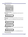
C Press the {U} or {T} key to display [Color Calibrate], and then press the {#
Enter} key.
❒ If you perform only correction 2, proceed to step L.
D Check [Start Calibr. 1] is displayed, and then press the {# Enter} key.
E Check [Yes] is displayed, and press {# Enter} key to print gradation correction sheet 1.
F Set the gradation correction value of the highlighted part using correc-
tion 1. For setting K (black) gradation, hold the correction value (0-6) for
“K” of the correction value setting sheet 1 over the color sample (K) for
gradation correction 1 of the Color Calibration Sample Sheet, and set
the numerical value of the closest color using either the {U} or {T} key.
Set the correction value using the supplied Color Calibration Sample Sheet
and the gradation correction sheet 1 printed in the previous step.
Set M (magenta), C (cyan), and Y (yellow) using the same method.
Calibrate 1:
K:3 M:3 C/Y:3/3
63
Cleaning and Adjusting the Printer
❒ Each time the {U} or {T} key is pressed, the value increases or decreases
respectively, in increments of 1.
❒ The correction value can be set between 0 and 6.
G Press the {# Enter} key after setting the K (black) gradation. The cursor
shifts to M (magenta).
Calibrate 1:
K:2 M:3 C/Y:3/3
H Set the gradation correction values for M (magenta), C (cyan), and Y (yellow) using the same procedure as for the K (black).
I If you finished all settings, ensure that the cursor is on the correction
value for Y (yellow), and then press the {# Enter} key.
Calibrate 1:
K:2 M:2 C/Y:2/2
The example shows the display of the control panel when the correction value
for each color is changed to 2.
J Check [Yes] is displayed, and press the {# Enter} key to print the correction result.
K Check
gradation correction sheet 1. To save the correction values,
check [Save and exit] is displayed and press the {# Enter} key. If you do not
want to save the correction values after this procedure, press the {U} or
{T} key to display [Exit don't save], and then press the {# Enter} key.
❒ If you complete this procedure without saving the correction values, the
changes will not be applied to subsequent print jobs.
Calibrate 1:
Save and exit
Calibrate 1:
Exit don't save
This concludes the setting for correction 1. Next, proceed to correction 2.
L Press the {T} key to display [Start Calibr. 2], and then press the {# Enter}
key.
64
Cleaning and Adjusting the Printer
M Check [Yes] is displayed, and then press the {# Enter} key to print gradation correction sheet 2.
N Perform the same operations as used for setting the gradation correction value using correction 1 to set the gradation correction value of the
middle part using correction 2.
O After completing all settings, press the {Online} key.
The initial screen appears.
❒ Displays on the screen are just examples.
Viewing the Color Calibration Sample Sheet and Gradation
Correction Sheet
The color gradation correction value setting sheet contains two color sample columns: the “Sample 1” column for setting the highlight part and the “Sample 2”
column for setting the middle part.
Similarly, there are two gradation correction sheets: “Gradation correction sheet
1” for setting the highlight part and “Gradation correction sheet 2” for setting the
middle part. Gradation correction sheet 1 is used for calibration 1, while Gradation correction sheet 2 is used for calibration 2.
❖ Color sample and correction values
The following explains how to view the color sample of the Color Calibration
Sample Sheet and the correction values of the gradation correction sheet.
This explanation uses setting K (black) as an example. The setting method for
M (magenta) is similar. For C/Y (cyan/yellow), the correction value is determined based on combinations of these two colors, although panel settings are
made for each color.
65
Cleaning and Adjusting the Printer
❒ Hold the correction value (0-6) for “K” of the correction value setting sheet
over the color sample of gradation correction 1 of the Color Calibration
Sample Sheet and search for a corrected color closest to that of the color
sample, and then set its correction value using the operation panel. The
currently set correction value is printed in red.
66
Cleaning and Adjusting the Printer
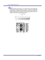
❖ Relationship between gradation correction sheet and display
The printed gradation correction sheet and display correspond as shown in
the following diagram. The gradation correction sheets are used to determine
the correction values for the colors K (black), M (magenta), C (cyan), and Y
(yellow). These values are set using the control panel.
❒ XXXX represents the printer model name.
A K (black) correction values
Adjust the printed color when only black toner is used. The currently set
correction value is printed in red.
B M (magenta) correction values
Adjust the printed color when only magenta toner is used. The currently set
correction value is printed in red.
C C (cyan)/Y (yellow) correction values
Correct the color printed when cyan and yellow are used. For C/Y (cyan/yellow), the correction value is determined based on a combination of
these two colors, although settings are made for separately each color.
D K, M, C/Y
The numerical value set at time of gradation correction sheet printing is displayed. This corresponds to the numerical value set using the operation
panel.
Resetting the gradation correction value to the initial value
Reset the correction value default.
67
Cleaning and Adjusting the Printer
A Press the {Menu} key.
The [Menu]screen appears.
B Press the {U} or {T} key to display [Maintenance], and then press the {#
Enter} key.
Menu:
Maintenance
The maintenance menu appears.
C Press the {U} or {T} key to display [Color Calibrate], and then press the {#
Enter} key.
D Press the {U} or {T} key to display [Reset], and then press the {# Enter}
key.
Color Calibrate:
Reset
A confirmation message is displayed.
Press # to reset
Calibration
E Press the {# Enter} key.
A message indicating the gradation correction value has returned to default,
is displayed.
Calibration was
reset
After about 2 seconds, the display returns to the [Color Calibrate: Reset] menu.
F Press the {Online} key.
The initial screen appears.
68
Cleaning and Adjusting the Printer
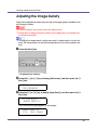
Adjusting the Image Density
Adjust the image density when the print side of the page appears shaded or the
print image is patchy.
❒ Extreme settings may create output that appears dirty.
❒ Image density settings should be made from the application or the printer driver whenever possible.
❒ Changing the image density setting can result in deterioration of color balance. We recommend you leave the image density at its factory default setting.
A Press the {Menu} key.
The [Menu]screen appears.
B Press the {U} or {T} key to display [Maintenance], and then press the {#
Enter} key.
Menu:
Maintenance
C Press the {U} or {T} key to display [Image Density], and then press the {#
Enter} key.
Maintenance:
Image Density
The following message appears on the display:
Image Density:
Prt. Test Sheet
69
Cleaning and Adjusting the Printer
D Press the {# Enter} key.
When following message appears on the display, press the {# Enter} key.
Prt. Test Sheet
Press # to start
Printing...
E Compare the colors on the printed image density test sheet with those
on the Image Density Adjusting Card.
❒ If the image density of the Image Density Adjusting Card is equal to the
framed part of the test sheet, do not adjust the image density value.
❒ If the image density of the Image Density Adjusting Card is equal to the
density shown above the frame, select “-” as the image density setting. If
the image density of the Image Density Adjusting Card is equal to the density shown below the frame, select “+” as the image density setting.
F Press the {U} or {T} key to select the color you want to adjust, and then
press the {# Enter} key.
Image Density:
Black
G Press the {U} or {T} key to set the image density value, and then press
the {# Enter} key.
Black:
(-10 +10)
0
❒ You can adjust the image density in 21 increments, from -10 to +10. Increasing the value makes printouts darker and decreasing the value makes
printouts lighter.
❒ Pressing the {U} or {T} key increases or decreases the value in increments of one.
To adjust another color, repeat steps F and G.
H Press the {Online} key.
The initial screen appears.
70
Cleaning and Adjusting the Printer
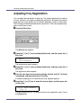
Adjusting Tray Registration
You can adjust the registration of each tray. The vertical adjustment is used for
all trays. Normally, you need not update the registration. But when the optional
paper feed unit or the duplex unit is installed, updating is useful in some cases.
The following procedure describes how to adjust tray 2. The same procedure applies to other trays as well.
A Press the {Menu} key.
The [Menu]screen appears.
B Press the {U} or {T} key to display [Maintenance], and then press the {#
Enter} key.
Menu:
Maintenance
The maintenance menu appears.
C Press the {U} or {T} key to display [Registration], and then press the {#
Enter} key.
The registration menu appears.
D Print the test sheet to preview the settings. Confirm that [Prt. Test Sheet]
is displayed, and then press the {# Enter} key.
A screen prompting you to select the tray to be adjusted appears.
E Press the {U} or {T} key to select the tray to adjust, and then press the
{# Enter} key.
Prt. Test Sheet:
Tray 2
The test sheet prints out. The display returns to the registration menu. Press
the {Escape} key.
71
Cleaning and Adjusting the Printer
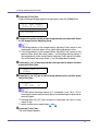
F Confirm the position of the image on the test sheet, and then adjust the
registration value.
In this setting, adjust the margins of the test sheet so that they are equal in
size.
G Press the {U} or {T} key to display [Adjustment], and then press the {#
Enter} key.
H Press the {U} or {T} key to display the parameter to be adjusted, and
then press the {# Enter} key.
Adjustment:
Horiz: Tray 2
I Press the {U} or {T} key to set the registration value (mm).
Horiz: Tray 2:
(-15 +15)
0
72
Cleaning and Adjusting the Printer
Increase the value to shift the print area in the positive direction, and decrease
to shift in the negative direction.
A
B
: Print Area
: Feed Direction
❒ Pressing the {U} or {T} key makes the value increase or decrease by 1.0
mm steps.
J Press the {# Enter} key.
The display returns to the print area [Adjustment] menu.
Registration:
Adjustment
K Print the test sheet to confirm the adjustment result.
L Press the {Online} key.
The initial screen appears.
73
Troubleshooting
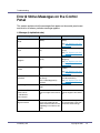
Error & Status Messages on the Control
Panel
This section explains what the messages that appear on the control panel mean
and what to do when a particular message appears.
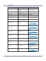
❖ Messages (in alphabetical order)
Messages
Add Toner
Black
Description
The printer is out of toner
(Black).
Recommended Action
Replace the toner cartridge
(Black).
See p.28 “Replacing the Toner Cartridge”.
Add Toner
Cyan
The printer is out of toner (Cy- Replace the toner cartridge
an).
(Cyan).
See p.28 “Replacing the Toner Cartridge”.
Add Toner
Magenta
The printer is out of toner (Ma- Replace the toner cartridge
genta).
(Magenta).
See p.28 “Replacing the Toner Cartridge”.
Add Toner
Yellow
The printer is out of toner (Yel- Replace the toner cartridge
low).
(Yellow).
See p.28 “Replacing the Toner Cartridge”.
Add Toner
XXX/XXX
The printer is out of the indicat- Replace the toner cartridge of
ed toner(s).
the indicated color(s).
XXX: Yellow/Magenta/Cyan/Black
See p.28 “Replacing the Toner Cartridge”.
Calibrating...
The printer is calibrating the
color.
Wait a while.
Call Service: EC
A communication error sent
A communication error sent
from the engine to the control- from the engine to the controller.
ler.
Power Off On
/ Call Service if
error reoccurs
Cannot check
Signal in Ad hoc
G1398504_1.00
An attempt to check the radio To check the radio signal , sesignal was made while the
lect Infrastructure in the comcommunication mode was set munication mode settings.
to [Ad hoc] in the interface settings.
Copyright © 2005
74
Troubleshooting
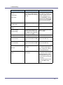
Messages
Description
Recommended Action
The paper size and type setting in the tray differs from that
of actual paper size and type in
the tray.
Load paper of the selected
size in the tray, and then
change the paper size setting
with the control panel. Or,
press {Form Feed}, and then
select the tray using the control panel. Or, press {Job Reset} to cancel the print job.
or Right Cover
The front cover or right cover is
open.
Close the front cover or right
cover.
Close Upper Left
The upper left cover open.
Close the upper left cover.
Change Setting
Tray #
/ Paper Size:
Paper Type:
Close Front and/
Cover
DHCP assigned
Cannot change
An attempt to change the IP
Make the change after setting
address, subnet mask or gate- DHCP to [Off].
way address was made while
DHCP was set to [On].
Energy Save Mode
In Energy Save Mode level 2.
No action required.
Error: Enter 10
An ID with an invalid number of
digits was entered for the WEP
key.
Enter the correct number of
digits for the WEP key.
An ID with an invalid number of
digits was entered for the WEP
key.
Enter the correct number of
digits for the WEP key.
or 26 characters
Error: Enter 5
or 13 characters
Hardware Problem
Ethernet
Hardware Problem
HDD
The printer identified an Ether- Turn the power off, and then
net error.
on. If the message appears
again, contact your sales or
service representative.
The printer identified a HDD
Board error.
Turn the power off, and then
on. Remove and re-install the
HDD board correctly. If the
message appears again, contact your sales or service representative.
See “Attaching Printer Hard
Disk Type 3000”, Setup
Guide.
75
Troubleshooting
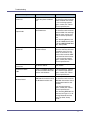
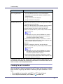
Messages
Hardware Problem
IEEE1394
Description
Recommended Action
The printer identified an IEEE
1394 interface board error.
Turn the power off, and then
on.
Remove and re-install the
IEEE 1394 interface board
correctly.
A Check the IEEE 1394 in-
terface board is correctly
attached to the computer.
B Check the IEEE 1394 in-
terface cable is securely
connected.
C Unplug the IEEE 1394 in-
terface cable which is connected to the printer.
D Restart the computer. If
the message appears
even after executing
above operation, proceed
to the following steps.
E Execute the utility tool for
IEEE 1394 interface board
that is stored in the following path in the CD-ROM
labeled “Printer Drivers
and Utilities”:
UTILITY 1394
❒ For details about using the
utility tool for IEEE 1394,
see the README file in
the same directory in the
CD-ROM. If the message
appears again, contact
your sales or service representative.
See “Attaching IEEE 1394 Interface Board Type B”, Setup
Guide.
Hardware Problem
Black PCU
The printer detected an error
in the black photo conductor
unit.
Turn the power off, and then
on. Remove and re-install the
photo conductor unit correctly. If the message appears
again, contact your sales or
service representative.
76
Troubleshooting
Messages
Hardware Problem
Color PCU
Hardware Problem
Option RAM
Description
Recommended Action
The printer detected an error
in the color photo conductor
unit.
Turn the power off, and then
on. Remove and re-install the
photo conductor unit correctly. If the message appears
again, contact your sales or
service representative.
The printer identified an optional RAM error.
Turn the power off, and then
on. Remove and re-install the
optional RAM. If the message
appears again, contact your
sales or service representative.
See ”Attaching Memory Unit
Type D 128MB, Memory Unit
Type E 256MB(SDRAM Module)”, Setup Guide.
Hardware Problem
Parallel I/F
Hardware Problem
Printer font
Hardware Problem
USB
Hardware Problem
Wireless Board
There is a problem with the
parallel interface.
If you use the parallel I/F, replace the interface cable that
caused the error. Turn the
power off, and then on. Remove and re-install the IEEE
1284 interface board correctly. If the message appears
again, contact your sales or
service representative.
Problems with the font file for
the Printer module.
It is necessary to replace the
print module.
There is a problem related to
the Universal Serial Bus Connection and Hardware.
Turn the power off, and then
on. If the message appears
again, contact your sales or
service representative.
An error was detected in the
IEEE 802.11b interface unit or
the Bluetooth interface unit.
Turn the power off, and then
on. Remove and re-install the
IEEE 802.11b interface unit or
the Bluetooth interface unit
correctly.
If the message appears
again, contact your sales or
service representative.
See “Attaching IEEE 802.11b
Interface Unit Type H” or “Attaching Bluetooth Interface
Unit Type 3245”, Setup
Guide.
77
Troubleshooting
Messages
Description
Recommended Action
The IEEE 802.11b interface
unit or the Bluetooth interface
unit could not be detected
when the power was turned
on. The IEEE 802.11b interface card or the Bluetooth interface card was removed
after the power was turned on.
An error was detected in the
IEEE 802.11b interface card or
the Bluetooth interface card.
Turn the power off, and then
on. Remove and re-install the
IEEE 802.11b interface unit or
the Bluetooth interface unit
correctly.
Hex Dump Mode
In Hex Dump Mode.
No action required.
Invalid Data
The printer has received irreg- Turn the power off, and then
ular data.
on. If the message appears
again, contact your sales or
service representative.
Hardware Problem
Wireless Card
Power Off On
Invalid Password
Try again
Load Correct
Size Paper
/ Press #
If the message appears
again, contact your sales or
service representative.
See “Attaching IEEE 802.11b
Interface Unit Type H” or “Attaching Bluetooth Interface
Unit Type 3245”, Setup
Guide.
The password entered using
Enter the correct password
the control panel is not correct. using the control panel.
The paper size set in the indicated tray differs from the setting made.
to continue
Load paper of the selected
size in the tray, and then
press the {# Enter} key to resume printing. If you want to
ignore the message and continue printing, press the {# Enter} key.
or Form Feed
The indicated tray is out of pa- Load paper into the indicated
per.
paper tray.
/ Paper Size:
#: tray number
Load Paper:Tray #
Paper Type:
Load Paper
or Form Feed
/ Paper Size:
Paper Type:
A The printer received a re-
quest for a paper type, or
paper size not supported
by printer, and Tray Locking is not applicable.
Change the setting of the indicated paper input tray, or
press {Job Reset} key. Form
Feed is not possible here.
B The paper type and size
loaded in the tray which the
printer searched using
Tray Locking is invalid for
Duplex Print.
Loading Toner...
The printer is loading toner.
Wait a while.
Menu Protected
The menu is protected and the
setting cannot be changed.
Wait for two seconds until the
previous display appears.
Cannot change
78
Troubleshooting
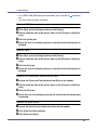
Messages
Description
Recommended Action
No Files exist
There are no files available for
Sample Print job or Locked
Print job.
Wait for two seconds until the
previous display appears.
Offline
The printer is offline and cannot print data.
Press {Online} key.
Please wait...
The printer is cooling down.
Wait a while.
Processing...
Print data is being processed.
Wait a while.
RC Gate
Cannot communicate with RC
Gate.
Check the device or the RC
Gate network connection.
Ready
The default ready message.
The printer is ready to use.
No action required.
Remove Misfeed
There is a misfeed in the fusing unit.
Remove the misfed paper.
connection error
B: Fusing Unit
Remove Misfeed
A: Internal Path
Remove Misfeed
Y: Paper Tray
Remove Misfeed
Z: Duplex Unit
Remove Paper
Standard Tray
Replace Black
PCU
Replace Black
PCU soon
Replace Color
PCU
See p.99 “When “Remove
Misfeed B: Fusing Unit” Appears”.
There is a misfeed in the print- Remove the misfed paper.
er.
See p.96 “When “Remove
Misfeed A: Internal Path” Appears”.
There is a misfeed in the input
tray, or the printer is not feeding paper.
There is a misfeed in the duplex unit.
Remove the misfed paper.
See p.102 “When “Remove
Misfeed Y: Paper Tray” Appears”.
Remove the misfed paper.
See p.104 “When “Remove
Misfeed Z: Duplex Unit” Appears”.
The standard output tray is full. Remove paper from the standard output tray.
It is time to replace the black
PCU.
Replace the black PCU.
See p.35 “Replacing the Photo Conductor Unit”.
The time to replace the black
PCU is soon.
Prepare to replace the black
PCU when the message [Replace Black PCU] appears on
the display.
It is time to replace the color
PCU.
Replace the color PCU.
See p.35 “Replacing the Photo Conductor Unit”.
79
Troubleshooting
Messages
Replace Color
PCU soon
Replace
Fusing Unit
Description
Recommended Action
The time to replace the color
PCU is soon.
Prepare to replace the color
PCU when the message [Replace Color PCU] appears on
the display.
It is time to replace the fusing
unit.
Replace the fusing unit with a
new one.
See p.44 “Replacing the Fusing Unit”.
Replace Fusing
Unit soon
Replace
Transfer Belt
The time to replace the fusing
unit soon.
Prepare to replace the fusing
unit when the message [Replace Fusing Unit] appears on
the display.
It is time to replace the transfer
belt.
Replace the transfer belt with
a new one.
See p.51 “Replacing the Intermediate Transfer Unit”.
Replace Transfer
Belt soon
Replace Used
Toner Bottle
The time to replace the transfer belt.
Prepare to replace the transfer belt when the message
[Replace Transfer Belt] appears
on the display.
It is time to replace the waste
toner bottle.
Replace the waste toner bottle.
See p.32 “Replacing the
Waste Toner Bottle”.
Reset Fusing
Unit correctly
Reset Paper
Bypass Tray
Reset PCU
correctly
XXX/XXX
There is no fusing unit, or the
fusing unit is not installed correctly.
Set the fusing unit correctly.
There is paper left in the bypass tray.
Remove paper from the bypass tray, and then reset the
paper.
The indicated photo conductor
unit(s) is/are not set correctly,
or not set.
Set the indicated photo conductor unit(s) correctly.
XXX: Yellow/ Magenta/Cyan/Black
See p.35 “Replacing the Photo Conductor Unit”.
The indicated toner cartridge
is not set correctly.
Set the indicated toner cartridge(s) correctly.
XXX: Yellow/Magenta/Cyan/Black
See p.28 “Replacing the Toner Cartridge”.
or Form Feed
The indicated paper input tray
is not set correctly, or not set.
Set the indicated paper input
tray correctly.
Resetting Job...
A job is being reset.
Wait a while.
ROM Update
The printer is waiting for updated data.
Don't turn off the printer while
it is waiting for data.
Reset Toner
XXX/XXX
Reset Tray #
Waiting for Data
80
Troubleshooting
Messages
ROM Update
Receiving Data
SC XXX-X
Power Off On
/ Call Service if
Description
Recommended Action
The printer is receiving updated data.
Don't turn off the printer while
it is receiving data.
Turn the power off and then
on. If the message appears
again, contact your sales or
service representative.
Turn the power off, and then
on. If the message appears
again, contact your sales or
service representative.
Authentication for the SD card
has failed.
Turn the power switch off and
then back on again. If the
message appears again, contact your sales or service representative.
The settings are being
changed.
Wait a while.
error reoccurs
SD authenticatn.
failed
Setting change
in process
Set Transfr.Belt
or UsedTonerBtl.
The transfer belt or waste ton- Set transfer belt or waste toner bottle is not set correctly, or er bottle correctly.
not set.
SSID not entered
This message appears if the
SSID has not been entered.
Enter the SSID.
Supply order
Supply order has failed.
The use is required to reset
the job.
failed
Toner is almost
empty: Black
Toner is almost
empty: Cyan
Toner is almost
empty: Magenta
Toner is almost
empty: Yellow
Update Mode Err.
Power Off On
Used Toner is
almost full
The printer is almost out of ton- Prepare to replace the toner
er (Black).
cartridge (Black) when the
message [Add Toner Black] appears on the display.
The printer is almost out of ton- Prepare to replace the toner
er (Cyan).
cartridge (Cyan) when the
message [Add Toner Cyan] appears on the display.
The printer is almost out of ton- Prepare to replace the toner
er (Magenta).
cartridge (Magenta) when the
message [Add Toner Magenta]
appears on the display.
The printer is almost out of ton- Prepare to replace the toner
er (Yellow).
cartridge (Yellw) when the
message [Add Toner Yellow]
appears on the display.
The printer has failed to start
updating data.
Turn the printer OFF and then
back ON to restart.
The waste toner bottle is almost full.
Prepare to replace the waste
toner bottle.
See p.32 “Replacing the
Waste Toner Bottle”.
81
Troubleshooting
Messages
Description
Recommended Action
Waiting...
The printer is waiting for the
next data to print.
Wait a while.
Warming up...
The printer is warming up and
not ready.
Wait until the printer signals
Ready.
82
Troubleshooting
Printer Does Not Print
Possible Cause
Is the power on?
Solutions
Confirm that the cable is securely plugged into the power outlet
and the printer.
Turn on the power.
Does the Online indicator
stay on?
If not, press {Online} key to light it.
Does the Alert indicator
stay red?
If so, check the error message on the display and take the required
action.
Is paper loaded?
Load paper into the paper tray or onto the bypass tray.
See p.15 “Loading Paper”.
Can you print a configuration page?
If you cannot print a configuration page, it probably indicates a
printer malfunction. Contact your sales or service representative.
See “Test Printing”, Setup Guide.
Is the interface cable connected securely to the
printer and the computer?
Connect the interface cable securely. If it has a fastener, fasten it
securely as well.
Are you using the correct
interface cable?
The type of interface cable you should use depends on the computer you use. Be sure to use the correct one.
If the cable is damaged or worn, replace it with a new one.
See p.111 “Specifications”.
Is the Data In indicator
blinking or lit after starting
the print job?
If not blinking or lit, the data is not being sent to the printer.
❖ If the printer is connected to the computer using the interface cable
Check the port connection setting is correct. For details about
checking the port connection, see p.84 “Checking the port connection”.
❖ Network Connection
Contact your network administrator.
How is the signal strength
when using the wireless
LAN?
❖ Ad hoc Mode or 802.11 Ad hoc Mode
Either move to a location where the signal is good, or remove
obstructions.
❖ Infrastructure Mode
Check the signal status from the [Maintenance] menu on the
control panel. If the signal is poor, either move to a location
where it is good, or remove obstructions.
83
Troubleshooting
Possible Cause
How is the signal strength
when using Bluetooth ?
When you use the optional
Bluetooth interface unit.
Solutions
Try the following:
•
Check the Bluetooth interface unit is installed properly.
•
Check there are no obstructions between computer, printer
and other devices.
•
Change the location of the computer.
•
Change the location of the printer.
SPP
A Make sure the machine you want to use appears in the 3Com
Bluetooth Connection Manager.
B Make sure “Bluetooth Serial Client (COMx)” appears under Cli-
ent Ports in the 3Com Bluetooth Connection Manager.
C Restart computer, this printer, and the other devices.
D Make sure no IEEE 802.11b (wireless LAN) or other Bluetooth
devices are in use.
❒ Interference may occur with the IEEE 802.11b wireless
LAN interface board. Such interference may affect the
transmission speed and other functions.
E Transmissions between computers, other devices, and this
printer can be blocked by obstructions. Move this printer, computers, and other devices, if necessary.
HCRP, BIP
A Restart the computer, this printer, and other devices.
B Make sure no IEEE 802.11b (wireless LAN) or other Bluetooth
devices are in use.
❒ Interference may occur with the IEEE 802.11b wireless
LAN interface board. Such interference may affect the
transmission speed and other functions.
C Transmissions between computers, other devices, and this
printer can be blocked by obstructions. Move this printer, computers, other devices, if necessary.
If printing still does not start, contact your sales or service representative. Consult with the store where the printer was purchased for information about the location of sales or service representatives.
Checking the port connection
When the printer is directly connected via the PC cable and the data-in indicator
does not flash or light up, the method of checking the port connection is as follows.
• For a parallel port connection, port LPT 1 or LPT 2 should be set.
• For a USB port connection, port USB00 (n) *1 should be set.
84
Troubleshooting
• For a IEEE 1394 (SCSI print) port connection, port 1394_00 (n) *1 should be
set.
*1
(n) is the number of printers connected.
Windows 95/98/Me
A Click [Start], point to [Settings] and then click [Printers].
B Click to select the icon of the printer. Next, on the [File] menu, click [Properties].
C Click the [Details] tab.
D Check the [Print to the following port] box to confirm that the correct port is
selected.
Windows 2000
A Click [Start], point to [Settings] and then click [Printers].
B Click to select the icon of the printer. Next, on the [File] menu, click [Properties].
C Click the [Port] tab.
D Check the [Print to the following port] box to confirm that the correct port is
selected.
Windows XP Professional, Windows Server 2003
A Access the [Printers and Faxes] window from [Start] on the taskbar.
B Click to select the icon of the printer. Next, on the [File] menu, click [Properties].
C Click the [Port] tab.
D Check the [Print to the following port(s).] box to confirm that the correct port
is selected.
Windows XP Home Edition
A Access the [Control Panel] window from [Start] on the taskbar.
B Click [Printers and Other Hardware].
C Click [Printers and Faxes].
85
Troubleshooting
D Click to select the icon of the printer. Next, on the [File] menu, click [Properties].
E Click the [Port] tab.
F Check the [Print to the following port(s).] box to confirm that the correct port
is selected.
Windows NT 4.0
A Click [Start], point to [Settings] and then click [Printers].
B Click to select the icon of the printer. After that, on the [File] menu, click
[Properties].
C Click the [Port] tab.
D Check the [Print to the following port] box to confirm that the correct port is
selected.
86
Troubleshooting
Other Printing Problems
Status
Toner smears appear on the
print side of the page.
Possible Causes, Descriptions, and Solutions
The paper setting may not be correct. For example, although
you are using thick paper, the setting for thick paper may not
be set.
•
Check the paper settings.
See p.9 “Types of Paper and Other Media”.
•
Check the printer driver's paper settings.
See the printer driver Help.
When [Replace Black PCU] or [Replace Color PCU] appears on
the display, replace the photo conductor unit.
See p.35 “Replacing the Photo Conductor Unit”.
Confirm that the paper is not curled or bent. Envelopes can
be curled easily. Flatten paper before loading.
See p.5 “Paper and Other Media Supported by This Printer”.
Paper jams occur frequently.
Number of paper set in the tray exceeds the limit. Confirm
that the top of the stack is not higher than the limit mark inside
the tray.
See p.15 “Loading Paper”.
There may be a gap between the rear guide and the paper,
or between the side guides and the paper in the paper tray.
Make sure there are no gaps.
See p.15 “Loading Paper”.
Paper is either too thick or too thin.
See p.5 “Paper and Other Media Supported by This Printer”.
Paper is bent or wrinkled. Use paper that have no bents or
wrinkles.
See p.5 “Paper and Other Media Supported by This Printer”.
Paper has already been printed on.
See p.5 “Paper and Other Media Supported by This Printer”.
Paper is damp. Use paper that has been stored properly.
See p.5 “Paper and Other Media Supported by This Printer”.
When loading paper, separate paper from each other.
87
Troubleshooting
Status
Possible Causes, Descriptions, and Solutions
Multiple pages are fed at once.
There may be a gap between the rear guide and the paper,
or between the side guides and the paper in the paper tray.
Make sure there are no gaps.
See p.15 “Loading Paper”.
Paper is either too thick or too thin.
See p.5 “Paper and Other Media Supported by This Printer”.
Paper has already been printed on.
See p.5 “Paper and Other Media Supported by This Printer”.
Number of paper set in the tray exceeds the limit. Confirm
that the top of the stack is not higher than the limit mark inside
the tray.
See p.5 “Paper and Other Media Supported by This Printer”.
Paper is static. Use paper that has been stored properly.
See p.5 “Paper and Other Media Supported by This Printer”.
When loading paper, separate paper from each other
Paper gets wrinkles.
Paper is damp. Use paper that has been stored properly.
See p.5 “Paper and Other Media Supported by This Printer”.
Paper is too thin.
See p.5 “Paper and Other Media Supported by This Printer”.
There may be a gap between the rear guide and the paper,
or between the side guides and the paper in the paper tray.
Make sure there are no gaps.
See p.15 “Loading Paper”.
The fusing unit is deteriorated or damaged. Replace the unit.
See p.44 “Replacing the Fusing Unit”.
Paper is not fed from the select- When you are using a Windows operating system, the printer
ed tray.
driver settings override those set using the control panel. Set
the desired input tray using the printer driver.
See the printer driver Help.
A printed image is different from When you use some functions, such as enlargement and rethe image on the computer's dis- duction, the layout of the image might be different from that
play.
displayed in the computer display.
You might have selected to replace True Type fonts with
printer fonts in the printing process.
To print an image similar to the image on the computer, make
the settings to print out True Type fonts as an image.
See the printer driver Help.
88
Troubleshooting
Status
Possible Causes, Descriptions, and Solutions
It takes too much time to resume
printing.
The data is so large or complex that it takes time to process
it. If the Data In indicator is blinking, the data is being processed. Just wait until it resumes.
If OHP transparencies or glossy paper is being used, printing
takes more time to start.
It takes too much time to complete the print job.
Photographs and other data intensive pages take a long time
for the printer to process, so simply wait when printing such
data.
Changing the settings with printer driver may help to speed
up printing.
See the printer driver Help.
The data is so large or complex that it takes time to process
it. If the Data In indicator is blinking, the data is being processed. Just wait until it resumes.
If [Waiting...] appears on the display, the printer is now warming up. Wait for a while.
Images are cut off, or excess
pages are printed.
If you are using paper smaller than the paper size selected in
the application, use the same size paper as that selected in
the application. If you cannot load paper of the correct size,
use the reduction function to reduce the image, and then
print.
See the printer driver Help.
The color of the printout is differ- The colors made using color toner are different from colors
ent from the color on the comdisplayed on the display in its production system.
puter's display.
When [Toner Saving] is checked under the [Print Quality] tab in
the printer driver's dialog box, the color gradation may appear differently.
See the printer driver Help.
The color of the printout is differ- If a specific color is missing, turn the power switch off and on.
ent from the color specified.
If this does not solve the problem, contact your sales or service representative.
Color changes extremely when
adjusted with the printer driver.
Do not extreme settings for the color balance under the [Print
Quality] tab in the printer driver's dialog box.
See the printer driver Help.
Photo images are coarse.
Some applications lower the resolution for making prints.
Color documents are printed in
black and white.
The printer driver is not set up for color printing.
See the printer driver Help.
Some applications print color files in black and white.
Fine dot pattern does not print.
Change the [Dithering:] setting in the printer driver's dialog
box.
See the printer driver Help.
89
Troubleshooting
Status
Possible Causes, Descriptions, and Solutions
Solid areas, lines or text are
Select [K (Black)] for [Gray Reproduction (Text/Line Art):] in the
shiny or glossy when created as printer driver's dialog box.
a mixture of cyan, magenta, yel- See the printer driver Help.
low.
Black gradation is not natural.
Select [CMY + K] for [Gray Reproduction (Text/Line Art):] in the
printer driver's dialog box.
See the printer driver Help.
Solid lines are printed as broken
lines.
Change the [Dithering:] setting in the printer driver's dialog
box.
See the printer driver Help.
A color is missing or partially
blurred.
Paper is damp. Use paper that has been stored properly.
See p.5 “Paper and Other Media Supported by This Printer”.
Toner is almost depleted. When the [Add Toner XXX] or [Toner
is almost empty: XXX] message appears on the display panel,
or the toner end LED on the control panel is lit, replace the
toner cartridge of the displayed color.
See p.28 “Replacing the Toner Cartridge”.
When [Replace Black PCU] or [Replace Color PCU] appears on
the display, replace the photo conductor unit.
See p.35 “Replacing the Photo Conductor Unit”.
Condensation may have collected. If rapid change in temperature or humidity occurs, use this printer only after it has acclimatized.
The whole printout is blurred.
Paper is damp. Use paper that has been stored properly.
See p.5 “Paper and Other Media Supported by This Printer”.
If you select [Toner Saving] on the [Print Quality] tab in the printer properties dialog box, printing is generally less dense.
See the printer driver Help.
Toner is almost depleted. When the [Add Toner XXX] or [Toner
is almost empty: XXX] message appears on the display panel,
or the toner end LED on the control panel is lit, replace the
toner cartridge of the displayed color.
See p.28 “Replacing the Toner Cartridge”.
When [Replace Black PCU] or [Replace Color PCU] appears on
the display, replace the photo conductor unit.
See p.35 “Replacing the Photo Conductor Unit”.
Condensation may have collected. If rapid change in temperature or humidity occurs, use this printer only after it has acclimatized.
90
Troubleshooting
Status
White streaks or color streaks
appear.
Possible Causes, Descriptions, and Solutions
Toner is almost depleted. When the [Add Toner XXX] or [Toner
is almost empty: XXX] message appears on the display panel,
or the toner end LED on the control panel is lit, replace the
toner cartridge of the displayed color.
See p.28 “Replacing the Toner Cartridge”.
When [Replace Black PCU] or [Replace Color PCU] appears on
the display, replace the photo conductor unit.
See p.35 “Replacing the Photo Conductor Unit”.
White or color rivers appear.
When [Replace Black PCU] or [Replace Color PCU] appears on
the display, replace the photo conductor unit.
See p.35 “Replacing the Photo Conductor Unit”.
The backs of printed sheets are
blemished.
When removing a jammed sheet, the inside of the printer
may have become dirtied. Print several sheets until they
come out clean.
If document size is larger than paper size, e.g. A4 document
on B5 paper, the back of the next printed sheet may be dirtied.
If rubbed with your finger, it
smears out.
The setting of the paper may not be correct. For example, although thick paper is used, the setting for thick paper may not
be set.
•
Check the paper settings of this machine.
See p.9 “Types of Paper and Other Media”.
•
Check the paper settings of the printer driver.
See the printer driver Help.
The fusing unit is deteriorated or damaged. Replace the unit.
See p.44 “Replacing the Fusing Unit”.
91
Troubleshooting
Status
Possible Causes, Descriptions, and Solutions
PDF Direct Print is not executed
(PDF file is not printed).
You must install an optional hard disk drive or set the value
of the [RAM Disk] in the System Menu to 2 MB or higher.
See “Attaching Printer Hard Disk Type 3000”, Setup
Guide for optional hard disk drive installation.
For [RAM Disk], see the “System Menu”, Software Guide.
After adding a memory unit and set the value of the [RAM
Disk] in the System Menu to 16 MB, value of the [RAM Disk]
returns to 0 MB if the memory unit is removed. If this happens, reset the value of the [RAM Disk] to 2 MB or higher.
For [RAM Disk], see the “System Menu”, Software Guide.
When printing a PDF with a password set, set the password
of the PDF file using the [PDF: Change PW] menu in [PDF Menu]
or Web Image Monitor.
For [PDF: Change PW], see the “PDF Menu” , Software
Guide.
For Web Image Monitor, see Help.
PDF files not allowed to be printed by the PDF file security
setting cannot be printed.
As a result of printing using PDF
Direct Printing, characters are
missing or misshapen.
Before printing, embed the font in the PDF file to be printed.
The paper size appears on the When using PDF Direct Print, printout requires paper set
control panel and printing is not within the PDF file. When a message indicating a paper size
performed with PDF Direct Print. appears, either place the indicated size in the paper tray, or
perform Form Feed.
Also, if [Sub Paper Size] in the System Menu is set to [Auto],
printing is performed assuming letter size and A4 size to be
the same size. For example, When a PDF file set to A4 size
paper is printed using PDF Direct Print and letter size paper
is installed in the paper tray, the file will print out. This applies
similarly to the opposite case.
If the problem cannot be solved, contact your sales or service representative.
92
Troubleshooting
Additional Troubleshooting
Problems
Solutions
Strange noise is heard.
If a supply was recently replaced or an option attached in the
area the strange noise is coming from, check the supply or
option is properly attached. If the strange noise persists, contact your sales or service representative.
No e-mail is received when an
Alert occurs, and after resolving
an Alert.
Confirm [Notify by Email] is [On] using the System Menu on the
Control Panel. See “System Menu”, Software Guide.
Access the printer through the Web browser, log on as an
Administrator on the Web Image Monitor, and then confirm
the following settings in [E-mail Notification]:
•
Device E-mail Address
•
Groups to Notify
•
Select Groups/Items to Notify
For details about the settings, see Web Image Monitor
Help.
Access the printer through the Web browser, log on as an
Administrator on the Web Image Monitor, and then confirm
the settings of the SMTP server in [E-mail].
For details about the settings, see Web Image Monitor
Help.
When the power is turned off before the e-mail is transmitted,
the e-mail will not be received.
Check the e-mail address set for the destination. Confirm the
printer's operation history using the Web Image Monitor's
System Log menu in [Network]. If the e-mail was sent but not
received, it is possible the destination was incorrect. Also
check the information concerning error mail from the e-mail
server.
The setting for [Notify by Email]
After changing the setting, turn the main unit's power off and
on the System Menu was
then back on again.
changed from [Off] to [On], but email is not arriving.
Error notification e-mail was received, but no error-solved email is received.
Check e-mail is set for sending using the Web Image Monitor's [E-mail Notification] at the time the error was fixed. You
must click the [Edit] button of [Detailed Settings of Each Item] in
[E-mail Notification], and set [Notify when error:] to [Occurs &
Fixed] on the displayed screen.
For details about the settings, see Web Image Monitor
Help.
93
Troubleshooting
Problems
Solutions
Alert Resolving is set for sending e-mail, but no Alert-resolved
e-mail is sent.
If the power of the main unit is turned off after an Alert occurs,
the Alert is resolved during the time the power is off: no Alertresolved e-mail is sent.
Alert Occurrence and Alert Resolving are set for sending email, but while no Alert Occurrence mail is received, Alert-resolved e-mail is received.
Alert-notification e-mail is not sent if the problem is resolved
before sending. However, an Alert-resolved e-mail is sent.
Alert-notification level was
If an Alert-notification e-mail, set with the earlier notification
changed, and e-mail stopped ar- level, arrives, later e-mail will not be sent, even if the notificariving.
tion level is changed after.
When no date information is included in sent e-mail, the mail
server has a malfunction.
Make the setting for obtaining time information from the
SNTP server. Refer to the Web Image Monitor's Help to the
settings.
Printing using Bluetooth is slow. When using the optional Bluetooth interface unit, do the following;
•
Transmit fewer print jobs.
•
Make sure no IEEE 802.11b (wireless LAN) or other Bluetooth devices are in use.
❒ Interference may occur with the IEEE 802.11b wireless LAN interface board. Such interference may affect the transmission speed and other functions.
•
Transmissions between the client computer and the machine can be blocked by obstructions. Move the machine
or client computer if necessary.
❒ When you use a Bluetooth connection, print jobs are
transmitted relatively slowly.
If the machine is still not operating satisfactorily, contact your sales or service
representative. Consult with the store where the printer was purchased for information about the location of sales or service representatives.
94
Removing Misfed Paper
Removing Misfed Paper
An error message appears if a paper misfeed occurs. The error message gives
the location of the misfeed.
❒ Misfed paper may be covered in toner. Be careful not to get toner on your
hands or clothes.
❒ Toner on prints made after removing misfed paper may be loose (inadequately fused). Make a few test prints until smudges no longer appear.
❒ Do not forcefully remove misfed paper, it will tear. Torn pieces remaining inside the printer will cause further misfeeds and possibly damage the printer.
G1398504_1.00
Copyright © 2005
95
Removing Misfed Paper
When “Remove Misfeed A: Internal Path”
Appears
• The inside of this machine gets very hot. Do not touch parts labelled “v”
(hot surface). Touching “v” labelled parts could result in burns.
A Open the front cover by pushing the front cover release button.
❒ Close the bypass tray if it is extended. If the bypass tray is extended, the
front cover does not open.
B Carefully remove any misfed paper.
❒ If misfed paper is difficult to move or stuck, proceed to the next step. Do
not pull forcefully on stuck or jammed paper.
96
Removing Misfed Paper
C Pull part “A” in the direction of the arrow, and then open the cover.
D Remove any misfed paper.
E Close the cover.
97
Removing Misfed Paper
F Close the front cover carefully.
98
Removing Misfed Paper
When “Remove Misfeed B: Fusing Unit”
Appears
• The inside of this machine gets very hot. Do not touch parts labelled “v”
(hot surface). Touching “v” labelled parts could result in burns.
A Open the front cover by pushing the front cover release button.
❒ Close the bypass tray if it is extended. If the bypass tray is extended, the
front cover does not open.
B Pull out levers “B1” on the left and right.
99
Removing Misfed Paper
C Remove any misfed paper.
❒ If misfed paper is difficult to move or stuck, proceed to the next step. Do
not pull forcefully on stuck or jammed paper.
D Pull part “B2” toward the front, and then open the guide board.
E Remove any misfed paper.
100
Removing Misfed Paper
F Return the guide board.
G Return levers “B1” on the left and right.
H Close the front cover carefully.
101
Removing Misfed Paper
When “Remove Misfeed Y: Paper Tray”
Appears
A Pull out the tray.
❒ Do not pull the tray out forcefully. If you do, the tray might fall and cause an
injury.
B Remove any misfed paper.
❖ Tray 1
❖ Tray 2/3
102
Removing Misfed Paper
C Slide the paper tray fully into the printer.
❒ Misfeeds can occur if the paper tray is not fully inserted. Make sure it is fully
inserted.
D Open the front cover by pushing the front cover release button, and then
close it to reset the misfeed condition.
❒ This procedure is also applicable to both the paper tray and the optional
paper feed unit.
103
Removing Misfed Paper
When “Remove Misfeed Z: Duplex Unit”
Appears
• The inside of this machine gets very hot. Do not touch parts labelled “v”
(hot surface). Touching “v” labelled parts could result in burns.
A Open the front cover by pushing the front cover release button.
❒ Close the bypass tray if it is extended. If the bypass tray is extended, the
front cover does not open.
B Pull the lever marked “PULL” on the duplex unit (
), and then pull up the
duplex unit until it stops ( ).
104
Removing Misfed Paper
C Remove any misfed paper.
D Close the front cover carefully.
105
Appendix
Moving and Transporting the Printer
• When moving the machine, each person should hold the handles that are
located on opposite sides, and then lift it slowly. Lifting it carelessly or dropping it may cause an injury.
• When you move the printer, remember to unplug the power cord from the
wall outlet to avoid a fire or an electric shock.
• When you pull out the plug from the socket, grip the plug, not the cord, to
avoid damaging the cord and causing a fire or an electric shock.
• When moving the printer after use, do not take out any of the Toners, Photo
Conductor Units, nor the waste toner bottle to prevent toner spill inside the
machine.
Repack the printer in its original packing materials for transporting.
❒ The printer weighs approximately 32 kg (70.5 lb.).
❒ Be sure to disconnect all cables from the printer before transporting it.
❒ The printer is a precision piece of machinery. Take care to avoid damage during shipment.
❒ If the optional paper feed unit is installed, remove it from the printer, and then
move them separately.
Moving the Printer
• When lifting the machine, use the inset grips on both sides. Otherwise the
printer could break or cause an injury if dropped.
• Before moving the machine, unplug the power cord from the wall outlet. If
the cord is unplugged abruptly, it could become damaged. Damaged plugs
or cords can cause an electrical or fire hazard.
Moving the printer in a short distance
A Be sure to check the following points:
• The power switch is turned off.
• The power cable is unplugged from the wall outlet.
• The interface cable is unplugged from the printer.
B If the external options are installed, remove them.
G1398504_1.00
Copyright © 2005
106
Appendix
See Setup Guide and follow the steps backwards for removing options.
C Lift the printer with two people by using the inset grips on both side of
the printer, and then move it horizontally to the place where you want to
install it.
D If you removed options, reinstall them.
See Setup Guide for installing options.
❒ Be sure to move the printer horizontally. To prevent toner from scattering,
move the printer slowly.
❒ If the optional paper feed unit is installed, remove it from the printer, and
then move them separately.
Transporting the Printer
When transporting the printer, leave consumables such as the toner cartridge,
photoconductor unit, and waste toner bottle in place inside the machine.
107
Appendix
Consumables
• Our products are engineered to meet the highest standards of quality and
functionality. When purchasing expendable supplies, we recommend using
only those specified by an authorized dealer.
Toner Cartridge
Toner cartridge
Average printable number of pages per bottle
*1
Color LP Toner Cassette Type165 Black
7,000 pages
Color LP Toner Cassette Type165 Cyan
6,000 pages
Color LP Toner Cassette Type165 Cyan SY
2,500 pages
Color LP Toner Cassette Type165 Magenta
Color LP Toner Cassette Type165 Magenta
SY
6,000 pages
2,500 pages
Color LP Toner Cassette Type165 Yellow
6,000 pages
Color LP Toner Cassette Type165 Yellow SY
2,500 pages
*1
A4/letter 5% test chart, 3 pages/ job.
The number of printable pages varies depending on which of the two different
types of toner cartridge you have installed.
❒ If toner cartridges are not changed when necessary, printing will become impossible. We recommend keeping a stock of bottles or purchasing them soon.
❒ The actual number of printable pages varies depending on the image volume
and density, number of pages to be printed at a time, paper type and paper
size used, and environmental conditions such as temperature and humidity.
❒ Toner cartridges may need to be changed sooner than indicated above due
to deterioration over the period of use.
❒ Toner cartridges (consumables) are not covered by warranty. However, if
there is problem, contact the store where they were purchased.
❒ When you first use this printer, use the four toner cartridges packaged with the
printer.
❒ Numbers of pages that can be printed using the toner cartridge supplied with
this printer are as follows:
Toner Cartridge
Black, Cyan, Magenta, Yellow
Average printable number of pages per bottle
2,500 pages
108
Appendix
Waste Toner Bottle
Name
Average printable number of pages *1
Waste Toner Bottle Type 165
*1
14,000 pages
A4/letter 5% test chart, 3 pages/ job.
❒ The actual number of printable pages varies depending on the image volume
and density, number of pages to be printed at a time, paper type and paper
size used, and environmental conditions such as temperature and humidity.
❒ If the waste toner bottles are not changed when necessary, printing will become impossible. We recommend keeping a stock of bottles or purchasing
them soon.
Photo Conductor Unit
Name
Average printable number of pages *1
Photo Conductor Unit Type 165 Black
15,000 pages
Photo Conductor Unit Type 165 Color
15,000 pages
*1
A4/letter 5% test chart, 3 pages/ job.
❒ The actual number of printable pages varies depending on the image volume
and density, number of pages to be printed at a time, paper type and paper
size used, and environmental conditions such as temperature and humidity.
❒ If the photo conductor unit is not changed when necessary, the quality of printing is not guaranteed. We recommend keeping a stock of photo conductor
units or purchasing one soon.
❒ Photo conductor unit (consumables) are not covered by warranty. However,
if there is problem, contact the store where they were purchased.
Intermediate Transfer Unit (Transfer Unit)
Name
Intermediate Transfer Unit Type 165
*1
Average printable number of pages *1
100,000 pages
A4/letter 5% test chart, 3 pages/ job.
❒ The actual number of printable pages varies depending on the image volume
and density, number of pages to be printed at a time, paper type and paper
size used, and environmental conditions such as temperature and humidity.
109
Appendix
❒ If the transfer unit is not changed when necessary, the quality of printing is not
guaranteed. We recommend keeping a stock of transfer unit or purchasing
one soon.
110
Appendix
Specifications
Mainframe
❖ Configuration:
Desktop
❖ Print Process:
Laser beam scanning & Electrophotographic printing
4 drums tandem method
❖ First Print Speed:
Monochrome: 13.5 sec or less (A4K)
Color: 14.5 sec or less (A4K)
❒ If the printer has not been used for a while, there may be a short delay before the first page starts printing.
❖ Printing Speed:
Monochrome: Maximum 21 pages per minute (A4K) *1
Color: Maximum 21 pages per minute (A4K) *1
*1
Printing speed may vary depending on the setting up environment.
❖ Resolution:
1200 × 1200 dpi (RPCS, PostScript 3, PCL 6)
1200 × 600 dpi (RPCS, PostScript 3, PCL 6)
600 × 600 dpi (RPCS, PostScript 3, PCL 5c/6)
300 × 300 dpi (PCL 5c *1 )
*1
monochrome only
❖ Paper size:
See p.5 “Paper and Other Media Supported by This Printer”.
❖ Paper Weight:
See p.5 “Paper and Other Media Supported by This Printer”.
❖ Media Type:
See p.5 “Paper and Other Media Supported by This Printer”.
❖ Paper Output Capacity:
Standard 250 sheets (80 g/m2, 20 lb.)
❖ Paper Input Capacity:
Standard Paper Tray
530 sheets *1
Bypass Tray
100 sheets *1
111
Appendix
530 sheets × 1, 530 sheets × 2 *1
Optional Paper Feed Units
*1
Paper weight: 80 g/m2 (20 lb.)
❖ Power Source:
120 V, 60 Hz, 11 A or more
❖ Power Consumption:
Printing
1200 W or less (No power is used during
power off.)
Energy Saver
9 W or less
❖ Warm-up Time:
Less than 30 seconds (23°C, 71.6 F) *1
*1
When no error.
❖ Dimensions:
Width
Printer only (tray not
extended)
419 mm (16.5 inches)
Depth
Height
536 mm (21.1 inches)
398 mm (15.7 inches)
❖ Weight:
Approximately 32 kg (70.5 lb.) (toner cartridges and power cord included)
❖ Noise Emission *1 :
Sound Power Level
Mainframe only
Stand-by
49 dB (A)
During Printing
63 dB (A)
Sound Pressure level *2
Mainframe only
Stand-by
36 dB (A)
During Printing
50 dB (A)
*1
*2
The preceding measurements made in accordance with ISO7779 are actual values.
Measured at the position of a bystander.
❖ Memory:
Standard 128 MB, up to 512 MB (with the optional Memory Unit)
❖ Interface:
Standard:
• Ethernet (10/100Base-TX)
112
Appendix
• USB2.0
It requires a USB computer port and cable that support USB 2.0.
Optional:
• IEEE 1394 (SCSI print, IP over 1394)
• IEEE 802.11b (Wireless LAN)
• Parallel (Bidirectional IEEE1284)
• Bluetooth
❖ Printer Language:
RPCS, PJL, PCL 5c/6, PostScript 3, PDF
❖ Fonts:
PCL 5c
Agfa Monotype 35 Intellifonts, 10 TrueTypefonts, and 1 Bitmap font.
PostScript 3
136 fonts (Type 2:24, Type 14:112)
Options
Paper Feed Unit Type 3000
❖ Paper size:
A4K, B5K, Letter (81/2 × 11 inches) K, Legal (81/2 × 14 inches)K
❖ Dimensions (W × D × H):
410 × 536 × 147 mm (16.2 × 21.1 × 5.8 inches)
❖ Paper weight:
60.2 - 104.7 g/m2, (16 - 28 lb.)
❖ Weight:
Less than 7.5 kg (16.4 lb)
AD440 (Duplex Unit)
❖ Dimensions (W × D × H):
325 × 237 × 169 mm (12.8 × 9.4 × 2.7 inches)
❒ This option is built into the machine.
❖ Paper size:
A4, B5(JIS), 8 1/2 × 14, 81/2 × 11
❖ Paper weight:
60.2 - 104.7 g/m2 (16 - 28 lb.)
113
Appendix
❖ Weight:
Less than 0.8 kg (1.7 lb.)
Printer Hard Disk Type 3000
❖ Storage Capacity (Formatted):
10 GB
❖ Specifications:
• Spool print data to collate
• Spool Sample Print/Locked Print data
• Store PostScript fonts
• Store log data
❒ You can install PostScript fonts with this optional hard disk drive. With Mac
OS, types of fonts supported are PostScript Type 1 and PostScript Type 2.
To download them, use Printer Utility for Mac.
User Account Enhance Unit Type E
❖ Capacity:
128 KB
• Store User Code (up to 500 users)
Memory Unit Type D 128MB/Memory Unit Type E 256MB
❖ Module Type:
SO-DIMM (Small Outline Dual-in-line Memory Module)
❖ Memory Type:
SDRAM (Synchronous Dynamic RAM)
❖ Number of Pins:
200 pins
IEEE 1394 Interface Board Type B
❖ Interface:
IEEE Std. 1394-1955 compliant, IEEE Std. 1394-2000 compliant.
❖ Interface Connector:
IEEE 1394 (6 pins × 2)
❖ Required cable:
IEEE 1394 interface cable (6 pins x 4 pins, 6 pins x 6 pins)
114
Appendix
❒ You cannot plug devices together to create loops.
❒ Do not use a cable more than 4.5 meters long.
❖ Connectable number of devices in a bus:
Maximum 63
❖ Allowed cable hops in a bus:
Maximum 16
❖ Data Transmission:
400 Mbps (Maximum)
❖ Power supply:
Non power supply
Cable Power repeated (IEEE 1394a-2000 compliant)
IEEE 802.11b Interface Unit Type H
❖ Transmission Spec.:
Based on IEEE 802.11b (Wireless LAN)
❖ Protocol:
TCP/IP, NetBEUI, IPX/SPX, AppleTalk
❒ SmartDeviceMonitor and Web Image Monitor are supported.
❖ Data Transfer Speed:
Auto select from below speed
1 Mbps, 2 Mbps, 5.5 Mbps, 11 Mbps
❖ Frequency Range:
• Inch version:
2412-2462 MHz (1-11 channels)
• Metric version:
2412-2472 MHz (1-13 channels)
❖ Transmittable Distance:
1 Mbps 400 m *1
2 Mbps 270 m *1
5.5 Mbps 200 m *1
11 Mbps 140 m *1
*1
These figures are a guideline for outdoor use. In general, the transmittable distance indoors is 10-100 m, depending on the environment.
❖ Transmission Mode:
ad hoc mode and infrastructure mode
115
Appendix
IEEE 1284 Interface Board Type A
❖ Transmission Spec.:
IEEE 1284
❖ Required cable:
Standard IEEE 1284 compliant Micro Centronics 36 pin cable
Bluetooth Interface Unit Type 3245
❖ Supported Profiles:
• SPP (Serial Port Profile)
• HCRP (Hardcopy Cable Replacement Profile)
• BIP (Basic Imaging Profile)
❖ Frequency Range:
2 GHz ISM band
❖ Data Transmission Speed:
732 kbps
❒ The transmission speed is adjusted according to factors such as the distance and obstacles between the devices, radio signal condition and Bluetooth adaptor.
❖ Maximum Range:
10 m
116