1
CORDLESS SCANNING SYSTEM
SCANTEAM® 2070 BASE
IMAGETEAM™ 3870 LINEAR IMAGER
SCANTEAM® 5770 LASER
System Manual
Disclaimer
Welch Allyn Data Collection, Inc. (d/b/a Hand Held Products) reserves the right
to make changes in specifications and other information contained in this
document without prior notice, and the reader should in all cases consult Hand
Held Products to determine whether any such changes have been made. The
information in this publication does not represent a commitment on the part of
Hand Held Products.
Hand Held Products shall not be liable for technical or editorial errors or
omissions contained herein; nor for incidental or consequential damages
resulting from the furnishing, performance, or use of this material.
This document contains proprietary information which is protected by copyright.
All rights are reserved. No part of this document may be photocopied,
reproduced, or translated into another language without the prior written consent
of Hand Held Products.
2000 Welch Allyn Data Collection, Inc. All rights reserved.
Web Address: www.handheld.com
Statement of Agency Compliance
This device complies with part 15 of the FCC Rules. Operation is subject to the
following two conditions: (1) this device may not cause harmful interference, and
(2) this device must accept any interference received, including interference that
may cause undesired operation.
FCC Class B Compliance Statement
This equipment has been tested and found to comply with the limits for a Class
B digital device pursuant to part 15 of the FCC Rules. These limits are designed
to provide reasonable protection against harmful interference in a residential
installation. This equipment generates, uses, and can radiate radio frequency
energy and, if not installed and used in accordance with the instructions, may
cause harmful interference to radio communications. However, there is no
guarantee that interference will not occur in a particular installation. If this
equipment does cause harmful interference to radio or television reception,
which can be determined by turning the equipment off and on, the user is
encouraged to try to correct the interference by one or more of the following
measures:
• Reorient or relocate the receiving antenna.
• Increase the separation between the equipment and receiver.
• Connect the equipment into an outlet on a circuit different from that to
which the receiver is connected.
• Consult the dealer or an experienced radio or television technician for
help.
Caution: Any changes or modifications made to this device that are not
expressly approved by Hand Held Products may void the user’s authority to
operate the equipment.
Note: To maintain compliance with FCC Rules and Regulations, cables
connected to this device must be shielded cables, in which the cable shield
wire(s) have been grounded (tied) to the connector shell.
Canadian Notice
This equipment does not exceed the Class B limits for radio noise emissions as
described in the Radio Interference Regulations of the Canadian Department of
Communications.
Le present appareil numerique n’emet pas de bruits radioelectriques depassant
les limites applicables aux appareils numeriques de la classe B prescrites dans
le Reglement sur le brouillage radioelectrique edicte par le ministere des
Communications du Canada.
CDRH Laser Safety Statement - ST5770 Series Only
This product complies with US DHHS 21 CFR J Part 1040.10. This product is a
CLASS II LASER PRODUCT with a maximum output of 1.0 mW at 670
nanometers and continuous wave.
EN 60825-1 Laser Safety Statement - ST5770 Series Only
This product is classified as a CLASS 2 LASER PRODUCT with a maximum
output of 9.0 mW at 670 nanometers per EN 60825-1:1994, Issue 2, June 1997.
R&TTE Directive
The IMAGETEAM 3870, SCANTEAM 5770, and SCANTEAM 2070 are in
conformity with all essential requirements of the R&TTE Directive (1999/5/EC).
This equipment has been assessed to the following standards: ETS 300 328 TS
300 826 (November, 1997); EN 60950: 1992, Incl Amdt 1-4, 11
0168 signifying conformity with Class II
This product is marked with
product requirements specified in the R&TTE Directive.
The equipment is intended for use throughout the European Community, but its
authorization for use in France is restricted as follows: PAN European
Frequency Range: 2.402 - 2.480 GHz; Restricted Frequency Range for use in
France: 2.448 - 2.480 GHz.
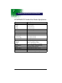
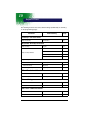
Regulatory and Safety Agency Approvals
Parameter
Specification
Electromagnetic Emissions/Immunity
U.S.A.
FCC Part 15, Class B - Verified
Canada
SOR 88/475, Class B - Verified
Europe
EN 55022 (CISPR22) Class B
ETS 300 826 Type Certified
Others
EMC 89/336/EEC
EN 50082-1:1997, EN55024
Safety
U.S.A./Canada
Australia
Europe
UL Listed, C22.2 No. 950/UL 1950
conforms to AS/NZS Standard
TÜV Rheinland GS Licensed, EN 60950 (IEC
950) (Scanner and Base only - not on battery)
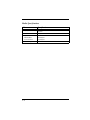
RF Approvals
U.S.A.
FCC Part 15.249 Certified
Australia
C-TIC
Canada
RSS 210 Certified
Europe
ETS 300 328 Certified
Singapore
Type Approval for Spread Spectrum System
The CE mark on the product indicates that the system has been
tested to and conforms with the provisions noted within the 89/336/
EEC Electromagnetic Compatibility Directive and the 73/23/EEC Low
Voltage Directive.
For further information please contact:
Hand Held Products (UK) Ltd.
1st Floor
Dallam Court Dallam Lane
Warrington, Cheshire WA2 7LT
England
Hand Held Products shall not be liable for use of our product with equipment (i.e.,
power supplies, personal computers, etc.) that is not CE marked and does not
comply with the Low Voltage Directive.
C.S.A. Statement
This product must be used with a certified Class 2 Power
supply or be powered by a certified SELV (Safety Extra Low
Voltage) output.
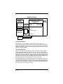
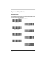
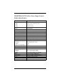
Enlarged Views of Regulatory Labels - IT3870
MAY 2000
Model # IMAGETEAM 3870
Item # 3870XX-XX
S / N 12345
SW 1.6/1.08
REV
Manufactured
Welch Allyn, Skaneateles Falls
New York 13153-0187, USA
See User Guide for Patent Information
Made in USA
IT3870 Scanner
Left Side View
IT3870 Scanner
Right Side View
Complies with (en conformite avec):
FCC PART 15
CANADA ICES-003
See manual
(Reféréz-vous à la documentation)
CISPR 22 CLASS B
Contains TX FCC ID: EHAUL
ISC: RSS/CNR 210
CANADA: 31101021090A
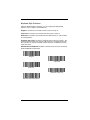
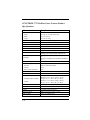
Enlarged Views of Regulatory Labels - ST5770
MAY 2000
Model # IMAGETEAM 3870
Item # 3870XX-XX
S / N 12345
SW 1.6/1.08
REV
Manufactured
Welch Allyn, Skaneateles Falls
New York 13153-0187, USA
See User Guide for Patent Information
Made in USA
ST5770 Scanner
Left Side View
ST5770
Right Side View
Complies with (en conformite avec):
FCC PART 15
CANADA ICES-003
See manual
(Reféréz-vous à la documentation)
CISPR 22 CLASS B
Contains TX FCC ID: EHAUL
ISC:RSS/CNR 210
CANADA: 31101021090A
Enlarged Views of Regulatory Labels - ST2070
ST2070 Base - Bottom
This device complies with Part 15 of the FCC Rules
and with RSS-210 of Industry Canada. Operation
is subjected to the following two conditions: (1)
This device may not cause harmful interference,
and (2) This device must accept any interference
received, including interference that can cause undesired operation.
Canada ICES-003
See Manual (Reféréz-vous à la documentation)
CISPR 22 CLASS B
Contains TX FCC ID: EHAUL
ISC: RSS/CNR 210
CANADA: 12231021090A
Table of Contents
Chapter 1 - Introduction and Installation
Introduction........................................................................... 1-1
Cordless System: Main Components.................................... 1-2
About the Charge Pack ......................................................... 1-3
Charging Your Charge Pack .......................................... 1-4
Setting Up and Connecting the Cordless System........... 1-6
Connecting More Scanners to the System ............................ 1-9
Beeper and LED Sequences and Meaning - IT3870 .......... 1-10
Beeper and LED Sequences and Meaning - ST5770.......... 1-11
ST5770 Scanner Beep Indication................................. 1-11
LED Sequences and Meaning - ST2070............................. 1-12
Basic Operation of the Cordless System ............................ 1-12
System Conditions ....................................................... 1-14
Communication Between the Cordless System
and the Host.................................................................. 1-16
Auxiliary Port............................................................... 1-18
Accessories for the Cordless System .................................. 1-20
Chapter 2 - Quick Start & Interface Menu
Introduction........................................................................... 2-1
Plug and Play Selections....................................................... 2-2
Industrial Interface: IBM PC.......................................... 2-2
Industrial Interface, Aux Port: RS-232 .......................... 2-2
IBM 468X/9X Ports 5B, 9B, and 17 Interface............... 2-3
Industrial Interface, Aux Port: Wand Emulation
Black High ..................................................................... 2-4
Industrial Interface, Aux Port: Wand Emulation
White High ..................................................................... 2-4
Non Decoded Laser Emulation (HHLC)....................... 2-5
Terminal Interface Selections ............................................... 2-6
Supported Terminals ...................................................... 2-6
i
Keyboard and Delays Selections........................................... 2-8
Keyboard Country .......................................................... 2-8
Keyboard Style Selections.............................................. 2-9
Keyboard Style Modifiers ............................................ 2-10
Output Delays Selection ............................................... 2-11
Wand Emulation Selections ................................................ 2-12
Transmission Rate Selection ........................................ 2-12
Output Polarity Selection.............................................. 2-13
Power Settings..................................................................... 2-14
Base Low Power Mode................................................. 2-14
Battery Conservation Mode ......................................... 2-15
Timeout Period Selections............................................ 2-16
Factory Default and Revision Report Selections ................ 2-17
Reset Factory Settings .................................................. 2-17
Revision Report ............................................................ 2-17
Chapter 3 - Communications Menu
Introduction ........................................................................... 3-1
Default Host Port Protocol .................................................... 3-2
Baud Rate Selection........................................................ 3-2
Parity Selection............................................................... 3-3
Word Length Data Bits Selection................................... 3-3
Word Length Stop Bits Selection ................................... 3-4
Hardware Flow Control Selection .................................. 3-4
Serial Wedge Output Selection....................................... 3-5
Host ACK Enable ........................................................... 3-7
Default Auxiliary Port Protocol .......................................... 3-11
Baud Rate Selection...................................................... 3-11
Parity Selection............................................................. 3-12
Word Length Data Bits Selection................................. 3-12
Word Length Stop Bits Selection ................................. 3-13
Hardware Flow Control Selection ................................ 3-13
IBM 4683 Async Address Selections........................... 3-14
Data Character Selection .............................................. 3-16
ii
Aux Prefix/Suffix Selections...............................................3-17
Decimal to Hex to ASCII Conversion Chart ................3-19
Aux Prefix Selection .....................................................3-20
Aux Suffix Selection.....................................................3-20
Exit Selection for Aux Prefix / Suffix ..........................3-20
Aux Prefix On/Off ........................................................3-21
Aux Suffix On/Off ........................................................3-21
Aux Port I.D. Transmit Selection .................................3-21
Aux Format Editor Commands.....................................3-24
Aux Data Format Editor ...............................................3-26
Aux Data Formatter ......................................................3-26
Alternate Aux Data Formats .........................................3-27
Chapter 4 - Application Work Group Menu
Introduction ...........................................................................4-1
Output Selections ..................................................................4-2
Application Work Group Selection ................................4-2
Remove Scanner Selection .............................................4-3
Beeper Volume Selection ...............................................4-3
Beeper Pitch ....................................................................4-4
Scanner Voting Selection................................................4-4
Laser Marker Beam (ST5770 only) ................................4-5
AIM I.D. Prefix...............................................................4-6
Code I.D. Prefix ..............................................................4-6
Symbology Chart...................................................................4-7
Prefix/Suffix Selections.........................................................4-8
Prefix Selections ...........................................................4-11
Suffix Selections ...........................................................4-11
Exit Selection for Prefix/Suffix ....................................4-12
Work Group Prefix On/Off 4-13
Suffix On/Off ................................................................4-13
Decimal to Hex to ASCII Conversion Chart 4-14
iii
Data Formatter Selections ................................................... 4-15
Data Format Editor Commands.................................... 4-16
Data Format Editor ....................................................... 4-18
Data Formatter.............................................................. 4-18
Require Data Format .................................................... 4-19
Decode Beep Selection 4-20
Alternate Data Formats................................................. 4-20
Chapter 5 - Symbology Menu
Introduction ........................................................................... 5-1
Codabar ................................................................................. 5-2
Start/Stop Characters ...................................................... 5-2
Codabar Check Character............................................... 5-4
Concatenation ................................................................. 5-4
Code 39 ................................................................................. 5-6
Start/Stop Characters ...................................................... 5-6
Check Character ............................................................. 5-8
Full ASCII ...................................................................... 5-9
Append.......................................................................... 5-10
Code 93 ............................................................................... 5-11
Interleaved 2 of 5 ................................................................ 5-13
Check Digit................................................................... 5-15
Code 2 of 5 .......................................................................... 5-16
Matrix 2 of 5........................................................................ 5-18
...................................................................................... 5-19
Code 11 ............................................................................... 5-20
Code 11 Check Digits Required ................................... 5-20
...................................................................................... 5-21
Code 128 ............................................................................. 5-22
...................................................................................... 5-23
<GS> Substitution ........................................................ 5-24
ISBT 128....................................................................... 5-24
Telepen................................................................................ 5-25
...................................................................................... 5-26
Telepen Output ............................................................. 5-26
iv
China Post Code (IT3870 only)...........................................5-27
RSS Expanded Message Length ...................................5-30
PDF417 (IT3870PDF only).................................................5-31
PDF417 Message Length..............................................5-32
Show GLI Blocks .........................................................5-33
Macro PDF417..............................................................5-34
Show Macro Control Blocks.........................................5-34
Scan Diagnostics...........................................................5-35
PDF417 Learn Mode ....................................................5-35
MicroPDF417 (IT3870PDF only) .......................................5-36
MicroPDF417 Message Length ....................................5-37
EAN•UCC Composite Symbology (IT3870PDF only) ......5-38
EAN•UCC Composite.........................................................5-38
EAN•UCC Composite Symbology Message Length....5-39
EAN/JAN 8 .........................................................................5-40
EAN/JAN8 Check Digit ...............................................5-40
EAN/JAN 13 .......................................................................5-41
EAN/JAN 13.................................................................5-41
EAN/JAN13 Check Digit .............................................5-41
ISBN .............................................................................5-41
UPC A .................................................................................5-42
UPC A Check Digit ......................................................5-43
Number System.............................................................5-43
UPC E0................................................................................5-44
UPC E0 Check Digit.....................................................5-44
Number System.............................................................5-44
Version E Expand .........................................................5-45
UPC E1................................................................................5-45
EAN/UPC Addenda ...........................................................5-46
EAN Addenda ..............................................................5-46
UPC Addenda ...............................................................5-47
Chapter 6 - Supported Interface Keys
Keyboard Function Relationships .........................................6-1
Supported Interface Keys ......................................................6-3
v
Chapter 7 - Product Specifications and Pinouts
SCANTEAM 2070 Cordless Base Product Specifications... 7-1
Radio Specifications.............................................................. 7-2
IMAGETEAM 3870 Cordless Linear Imager Scanner Product
Specifications ..................................................................... 7-3
SCANTEAM 5770 Cordless Laser Scanner Product Specifications .................................................................................... 7-4
Charge Pack Specifications (CLESS/NIMH/S and 34/5770/
NIMH/S)......................................................................... 7-5
Connectors & Pinouts ........................................................... 7-6
Auxiliary RS-232/Wand Emulation Connector.............. 7-7
Keyboard/Terminal and RS-232 (Host Port) Connector 7-8
External Power Connector.............................................. 7-9
Cordless Base Dimensions - ST2070.................................. 7-10
Cordless Scanner Dimensions - IT3870.............................. 7-11
Cordless Scanner Dimensions - ST5770............................. 7-12
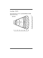
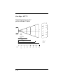
Scan Maps - IT3870 ............................................................ 7-13
Typical Performance at 20° C for IMAGETEAM 3870HD
(measured in inches)..................................................... 7-13
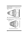
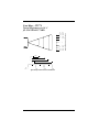
Typical Performance at 20° C for IMAGETEAM 3870LX
(Measured in inches) .................................................... 7-14
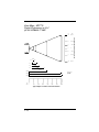
Typical Performance at 20° C for IMAGETEAM
3870PDF, Linear (Measured in inches)........................ 7-14
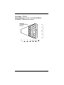
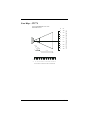
Typical Performance at 20° C for IMAGETEAM
3870PDF417 (Measured in inches) .............................. 7-15
Scan Maps - ST5770 ........................................................... 7-16
Typical Performance at 20° C
for SCANTEAM 5770STD .......................................... 7-16
Typical Performance at 20° C
for SCANTEAM 5770HD............................................ 7-17
Typical Performance at 20° C
for SCANTEAM 5770HV............................................ 7-18
vi
Chapter 8 - Maintenance and Troubleshooting
Maintenance ..........................................................................8-1
Cleaning the Scan Window of the Cordless Scanner .....8-1
Examining the Cordless Scanner and Cordless Base Housings..................................................................................8-1
Care and Handling of the Charge Pack...........................8-2
Replacing the Interface Cable.........................................8-2
Recharging and Replacing the Cordless Scanner’s Charge
Pack.................................................................................8-2
To Reset Factory Settings ...............................................8-2
Troubleshooting.....................................................................8-3
Chapter 9 - Customer Support
Obtaining Factory Service.....................................................9-1
Help Desk ..............................................................................9-3
Limited Warranty ..................................................................9-4
vii
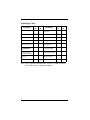
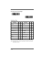
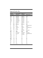
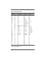
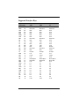
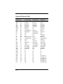
Chapter 10 - Default Chart
Country Code Selections .............................................. 10-1
Keyboard & Delays Selection ...................................... 10-1
Wand Emulation Selections.......................................... 10-1
Power Settings .............................................................. 10-1
Host Port Communications........................................... 10-1
Auxiliary Port Communications................................... 10-2
Output Selections (User Feedback) .............................. 10-3
Prefix/Suffix Selections................................................ 10-3
Data Formatter Selections ............................................ 10-3
Codabar Selections ....................................................... 10-3
Code 39 Selection......................................................... 10-4
Code 93 Selection......................................................... 10-4
Interleaved 2 of 5 Selection .......................................... 10-4
Code 2 of 5 Selection.................................................... 10-4
Matrix 2 of 5 Selection ................................................. 10-4
Code 11 Selection......................................................... 10-4
Code 128 Selection....................................................... 10-5
Telepen Selection ......................................................... 10-5
China Post Code Selection ........................................... 10-5
RSS-14 Selection.......................................................... 10-5
PDF417 Selection ......................................................... 10-5
MicroPDF417 Selection ............................................... 10-6
EAN•UCC Composite Symbology Selection............... 10-6
EAN / JAN 8 Selection................................................. 10-6
EAN / JAN 13 Selection............................................... 10-6
UPC A Selection........................................................... 10-6
UPC E0 Selection ......................................................... 10-6
UPC E1 Selection ......................................................... 10-7
EAN/UPC Addenda Selection...................................... 10-7
viii
1
Introduction and Installation
Introduction
The cordless scanning system consists of the SCANTEAM 2070 Base unit and
at least one IMAGETEAM 3870 Cordless Linear Imager or SCANTEAM 5770
Cordless Laser Scanner. Up to nine scanners may be associated with one base.
Each cordless scanner has a removable, rechargeable charge pack and
provides real time decoding within a 50 foot (15m) to 100 foot (30m) radius of the
base unit depending on the environment.
The cordless system is an economical, durable solution for a wide variety of
portable data collection applications. The cordless system features:
• a tough, ergonomic thermoplastic housing for comfort and durability.
• recognition and decoding of the most popular, industry-standard bar code
PDF417.
• scanner coverage of up to 7854 square feet (730 square meters).
• a wide range of interfaces that are compatible with many POS, keyboard
wedge, wand and laser emulation, RS-232 terminals, and legacy
decoders.
• visible and audible feedback for confirmation of a successful decode.
• a rechargeable battery designed to operate through a whole work day.
This manual contains information to help you set up, operate, and program the
cordless system. Product specifications, connector pinouts, scan maps, a
troubleshooting guide, and customer information are also provided.
The cordless system can be programmed for many communications parameters
and input/output protocols compatible to the host, as well as advanced data
editing and formatting. Programming is accomplished by using the single
programming bar codes in this manual.
This section contains the following information:
• Cordless System Main Components
• Charge Pack and Charging Information
• Cordless System Set Up and Connection
• Beeper and LED Sequences and Meaning
• Basic Operation of the Cordless System
• Communication Between the Cordless System and the Host
• Accessories for the Cordless System
1-1
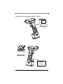
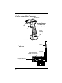
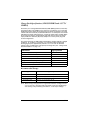
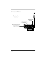
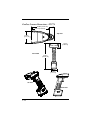
Cordless System: Main Components
Indicator LED
Cordless Scanner
Left Side View
Scan
Window
(with charge pack)
Trigger
Charge
Pack Clip
(2 places)
Charge Pack
Antenna
Cordless Base
Back View
External Power
Connector
Keyboard/Terminal
and RS-232 Connector
(Host Port)
Aux RS-232, Service Port,
and Wand Emulation
Output Connector
1-2
About the Charge Pack
(CLESS/NIMH/S and 34/5770/NIMH/S)
Power is supplied to the cordless scanner by a
rechargeable charge pack that snaps onto the
bottom of the scanner. Each scanner is shipped
with a charge pack. (See “Charge Pack
Specifications (CLESS/NIMH/S and 34/5770/
NIMH/S)” on page 7-5 for technical specifications.)
Note: Order backup charge pack(s) or
replacements from your distributor.
North American Charging Information
The charge pack is designed to plug into any twoprong North American AC power outlet for direct
charging. You need no additional equipment and you can recharge the pack
virtually anywhere.
Worldwide Charging Information
Since the charge pack is rated for both 120/240 V, 50 Hz/60Hz applications, it
may be charged worldwide. A custom charge strip is available to accommodate
the wide variety of electrical outlets internationally.
When the charge strip is used in 240 V applications, only use battery CLESS/
NIMH/S and 34/5770/NIMH/S. Do not attempt to charge battery part numbers:
34/5770/NICAD, 34/5770/NIMH, 34/5770/NIMH/F, or 34/5770/NICAD/F at 240
V.
Charge Pack Recommendations
• Batteries are shipped uncharged and need to be conditioned for full
capacity and longer life.
• To maintain the maximum charge capacity, batteries should be allowed to
fully discharge prior to charging. It is recommended that you establish a
process where a battery is used until it is fully discharged and fully
charged before its next use.
• Avoid using the charge pack in extreme temperatures.
• Do not disassemble the charge pack. There are no user-serviceable parts
in the charge pack.
• Avoid extended overcharging; do not leave the battery charging for more
than two weeks.
• Periodically, about every 6 months, repeat the charge pack conditioning.
1-3
Conditioning the Charge Pack
• Batteries are shipped uncharged and need to be conditioned for full
capacity and longer life.
• Charge the battery for 12 hours for the first two times to fully condition the
battery. (Fully discharge in between each initial charge.)
• Fully discharge the charge pack on a periodic basis by leaving the charge
pack attached to the scanner until the scanner no longer operates, about
24 hours. (Make sure all idle modes are disabled for this procedure -- see
“Battery Conservation Mode” on page 2-15).
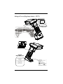
Charging Your Charge Pack
(CLESS/NIMH/S or 34/5770/NIMH/S)
Charge the charge pack by following the steps below:
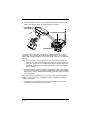
1. Detach the charge pack from the bottom of the scanner. (See figure below)
2. Fully charge the battery. Plug the
charge pack directly into any common 120 V AC outlet in North
America. If outside North America,
use the custom charge strip or
adaptor.
3. The LED on the bottom of the
charge pack blinks red temporarily
as part of the charge initialization
sequence. After initialization, the
LED remains solid red while the
battery is charging. The LED
shows green when the battery is
fully charged and ready to use.
Recharge Time: 6 hours at any voltage
at 20°C (68°F).
1-4
Press release Buttons
(2 Places)
4. After the charge pack is fully charged, attach it to the cordless scanner by
pressing the pack firmly (align the prongs on the pack with the mating receptacles) in the base of the scanner until the release buttons click, holding the
pack firmly in place. (When you attach a charged charge pack to the cordless scanner, you will hear a single beep.)
5. If you haven’t set up your Cordless System, turn to “Setting Up and Connecting the Cordless System” on page 1-6 for instructions.
6. If the scanner wasn’t previously associated to the base, scan the association
bar code on the top of the base. If the scanner was previously associated to
a base, it will automatically re-associate. (The association process takes
about ten seconds.)
When the charge pack needs recharging, the yellow LED on top of the scanner
pulses in short, continuous blinks when the trigger is pulled. If the LED stops
flashing when the temperature lowers or you do not use the charge pack for
some time, you still need to charge the charge pack.
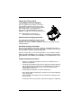
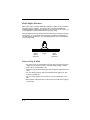
Proper Disposal of the Charge Pack
When the charge pack has reached the end of its useful life,
the batteries should be disposed of by a qualified recycler or
hazardous materials handler. Do not incinerate the charge
pack or dispose of the charge pack with general waste
materials. Contact the Product Service Department (see page
9-1) for recycling or disposal information.
1-5
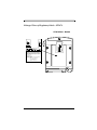
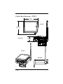
Setting Up and Connecting the Cordless System
Install the base and cordless scanner by following the steps shown below:
Important: Make sure the cordless scanner’s charge pack has been fully
charged. See “Charging Your Charge Pack” on page 1-4 for charging
instructions.
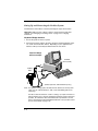
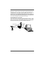
Keyboard Wedge Interface
1. Turn off the power to the host system.
2. Connect the interface cable to the base and to the terminal/computer (steps
1-3, shown in the illustration below). Depending on your application, the
interface cable you need may be different than the one shown.
Keyboard Wedge
Interface Example
Terminal
(Host system)
3
Cordless
Base
Disconnect
2
1
(Cable, keyboard, and terminal may vary.)
Note: For optimal coverage, place the base and its antenna as far away from
other sources of RF interference, with a clear transmitting path to the
scanner(s).
The base can be mounted on a wall or a ceiling. Try to place the base so
that the antenna is in a vertical (straight up and down) position whenever
possible. An extra Base Association Bar Code is provided in case the
base is mounted where the label might be difficult to scan (the Association
process is described on page 1-8).
1-6
RS-232 Interface
In an RS-232 configuration, connect your interface cable between the base unit
and the host system (steps 1-3, shown in the illustration below). You also need
to use an external power supply. Contact your distributor for more information
on ordering power supplies or RS-232 cables, including a “Y” extension power
cable to mount the base for best RF coverage.
RS-232 Interface Example
Terminal
(Host system)
22
Cordless
Base
1
3
Power Supply
(Cable, keyboard, and terminal may vary.)
3. Turn on the power to the host system. Verify that the base is on; the green
LED on top of the unit should be on. (The base does not have a beeper.)
1-7
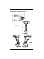
4. Using the cordless scanner, scan the Association Bar Code (the bar code
label on the top of the base) to link that scanner to the base.
Linear Imager or
Laser Scanner
Association Bar Code
Cordless Base
Two quick beeps followed by clicking, then a single beep indicates a “good”
association. The scanner is in communication with the base. If the scanner
clicks for 30 seconds and signals an error (triple beep), it has not associated with
the base.
Note: After association, if the charge pack is removed from the scanner and
replaced, the scanner automatically reassociates to the base, if the base
has power. In this case, the scanner beeps when a charged charge pack
is installed, then beeps a second time after full association, typically five to
ten seconds later.
5. After your cordless scanner has been associated with its base unit, program
the system to work with your terminal or computer by scanning the Terminal
Setup Codes. Use the Supported Terminal list (page 2-6) to scan your terminal’s Terminal ID.
With Plug and Play programming, you scan only one bar code to program the
cordless system to work with a designated interface, including any required
prefixes and suffixes.
6. To determine if your cordless system is set up correctly, scan one of the
sample bar codes in the back of this manual.
1-8
Connecting More Scanners to the System
Up to nine cordless scanners may be associated with one base unit. Add more
cordless scanners to a base unit by following the steps shown below:
1. Make sure the cordless scanner’s charge pack has been fully charged.
2. Scan the Association Bar Code (the bar code label on the top of the base) to
link each scanner to the base.
The base stores a unique I.D. for each scanner (up to nine) to identify the
scanner during data communication. Two beeps followed by clicking, then a
single beep from the scanner indicates a “good” association. The base rejects a
tenth cordless scanner trying to link to its network, sending the scanner an error
command. (A rejected scanner beeps three times, indicating an unsuccessful
association.)
Note: When you associate more scanners with the base, you don’t have to
program your cordless system to communicate with your terminal or
computer if you’ve already completed step 5 on page 1-8.
1-9
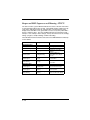
Beeper and LED Sequences and Meaning - IT3870
The base contains a green LED that indicates the status of the unit and verifies
its communication with the host system. The IT3870 contains a LED on the top
of the unit to indicate its power up, communication, and charge pack status.
Simply stated, red LED = error; green LED = success of any sort; yellow LED =
device is working or busy. The unit’s audible indicators have meaning as well -3 beeps = error; 2 beeps = menu change; 1 beep = all other successes; clicking/
ticking = progress; steady humming = PDF417 decoding
The table below lists the indication and cause of the LED illumination and beeps
for the IT3870.
LED Indication
Beeper Indication
Normal Operation
Steady Yellow
Yellow - blinking
None
None
Steady yellow
Clicking
Steady yellow
Ticking/humming
Steady green
1 beep
Red, blinking
3 beeps
Cause
Working/busy
Battery low
Indicates an association
attempt
Indicates PDF417 or
MicroPDF417 decoding in
process
Successful communication
or association
Failed communication or
association
Menu Operation
Steady green
Steady green
Red, blinking
1 - 10
Two beeps (high pitch,
medium pitch
Two beeps (both high
pitches)
3 beeps (all 3 high
pitches)
Successful menu change
Successful intermediate
menu operation
Unsuccessful menu change
Beeper and LED Sequences and Meaning - ST5770
The ST5770 contains a beeper and two LEDs on the top of the unit (green and
yellow) to indicate its power up, communication, and charge pack status. The
tables below list the indication and meaning of the beeps and LED illumination
scanner.
ST5770 Scanner LED Indication
Sequence
Meaning
Green LED on
Trigger pulled, out of range
Green LED on, 2 seconds
Successful decode and communication
Green LED blinks, 2 seconds
Successful decode with unsuccessful communication, or
unsuccessful clear to scanner
Green LED on, 2 seconds
Enter/exit programming mode, successful parameter
change in programming mode
Green LED blinks, 2 seconds
Unsuccessful parameter change in programming mode
Yellow LED on
Scanning, trigger pulled (in or out of range)
Yellow LED blinks
Low battery (trigger pulled)
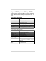
ST5770 Scanner Beep Indication
Sequence
Meaning
No beep
No scanning, scanning, or low battery (trigger pulled)
1 beep
Successful decode and communication
Clicking, then1 beep
Successful reassociation
Clicking only
Unsuccessful reassociation
2 beeps, clicks, then1 beep
Successful association to base
3 beeps - same pitch
Unsuccessful association to base (10th scanner), out of
range, or no network.
3 beeps - 2 high and 1 low
pitch
Enter/exit programming mode or successful association to
base. Successful or unsuccessful parameter change in programming mode.
4 beeps - low, high, low,
high pitch
Communication error: Successful decode with possible
unsuccessful communication to base. Check host to determine if data arrived properly.
1 - 11
LED Sequences and Meaning - ST2070
The base contains a green LED that indicates the status of the unit and verifies
its communication with the host system.
ST2070 Base LED Indication
Sequence
Meaning
LED on continuously
Power on, system idle
LED blinks, long duration
Power on, diagnostic error
LED blinks, short duration
Receiving data from scanner, host, or aux port
LED blinks, four long pulses
Communication error detected
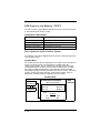
Basic Operation of the Cordless System
The following system block diagrams illustrate the basic operating components
of the cordless system.
Cordless Base
The cordless base provides the link between the cordless scanner and the host
system. The base contains a control/interface assembly and an RF
communication module. The RF communication module performs the data
exchange between the cordless scanner and the control/interface assembly.
The control assembly coordinates the central interface activities including:
transmitting/receiving commands and data to/from the host system, performing
software activities (parameter menuing, visual indicator support, power-on
diagnostics), and data translation required for the host system.
Cordless Base
RF Module
International
Control/Interface Assembly
(Base Circuit Board)
Control
Antenna
User I/O
Host I/O
LED
RF
Power
1 - 12
Menu I/O
Multipoint
I/O Ports
Host
Aux
Base
Housing
RF (Radio Frequency) Module Operation
The cordless system uses a state-of-the-art two-way 2.4 GHz frequency-hopping
spread spectrum radio to transmit and receive data between the scanner and the
base. Designed for point-to-point and multipoint-to-single point applications, the
radio transmits data at a rate of 1 megabit per second (Mbps). The radio
operates using a license free ISM band, which sends relatively small data
packets at a fast data rate over a radio signal with randomly changing
frequencies, makes the cordless system highly responsive to a wide variety of
data collection applications and resistant to noisy RF environments.
The RF radio used in the cordless system has been tested and approved as
complying with the two leading standards-setting organizations that serve as
regulatory models for compliance in most countries. In North America, the radio
is approved under the standards in FCC B Part 15.249 regulations and, in
Europe, under the standards in ETS 300 328 regulations.
Cordless Scanner
The cordless scanner enables fast and accurate bar code scanning using a noncontact linear imager or laser input engine. The scanner maintains radio
communication with the base unit from 50 feet (15m) to 100 feet (30m)
depending on the environment.
The scanner is comprised of a linear imager or laser scan engine, a decode/
control assembly, and an RF communication module. The scan engine performs
the bar code image illumination and sensing. The decode/control assembly
coordinates the central communication activities including: capturing and
decoding the bar code image data, performing software activities (parameter
menuing, visual indicator support, low battery indication), and data translation
required for the host system. The RF communication module performs the data
exchange between the scanner and the base.
1 - 13
Cordless Scanner
Scanner Assembly
Engine
Assembly
Decode/Control Assembly
(Handle Board)
Scan Engine
(Linear ImagHHLC I/O
er or Laser
Engine Port
Control
Menu I/O
Trig/Decode
Power Mgmt
Beeper Port
Beeper
Antenna
Trigger
Handle
Housing
RF
Module
RF Port
Download Port
Engine Hsg
Window/Lt Pipe
Charge Port
Charge Pack
System Conditions
The components of the cordless system interact in specific ways as you
associate one or more scanners to a base, as you move a scanner out of range,
bring a scanner back in range, replace a scanner charge pack, or swap scanners
between two cordless systems. The following information explains the cordless
system operating conditions.
Association Process
After you scan the association label, the base synchronizes radio parameters
and the work group parameter table in the scanner. The work group table is
uploaded during the clicking sequence. Two beeps, clicking, then a single beep
indicates the process is complete. The base blinks while it is sending the table
to the scanner. Until the table is uploaded, scanning and data transmission is
interrupted. If the base is off or not working properly, the scanner emits an error
(triple) beep after trying for 30 seconds to associate to the base.
The work group table is also uploaded any time the base believes a previously
associated scanner wishes to join the network. A scanner always tries to join the
last base it was associated to, even if the scanner has been without power for
several days. The base allows a scanner to associate as long as there are fewer
than nine scanners associated to the base.
1 - 14
Scanner is Out of Range
The cordless scanner is always in communication with its base, even when it is
not transmitting bar code data. Whenever the scanner can’t communicate with
the base for a three second interval, it is out of range. If the trigger is pulled while
the scanner is out of range, the red LED illuminates on the IT3870 and the green
and yellow LEDs illuminate on the ST5770. When you scan a bar code, the
scanner issues 3 beeps and does not try to send data to the base.
Note: While the scanner is out of range, it consumes more power searching for
the base continuously. To conserve battery power, store the scanner with
the charge pack removed, or program it for Battery Conservation mode
(see page 2-15).
Scanner is Moved Back Into Range
The scanner silently rejoins (no beep after connecting and synchronizing with the
base) if the scanner has not been reset (charge pack disconnected and
reconnected), no menu codes have been scanned by other scanners in the work
group, and the base has not been reset (see Base Reset Conditions, next page).
Any one of these three conditions can cause the scanner to go through a
reassociation process (definition on page 1-16) when it is moved back in range.
If the scanner reassociates, you will hear a single beep when the reassociation
process (uploading of the parameter table) is complete.
If you believe you are in range and are still hearing a triple (error) beep, you may
have been removed from the base’s network. This could happen if the scanner
loses power or goes out of range for three seconds. Try scanning the association
label or reset the scanner by removing and reinserting the charge pack.
Replacing Charge Pack While Associated
When you insert the charge pack, the scanner beeps, followed by clicking.
During this period the work group parameter table is uploaded to the scanner
from the base. Scanning and data transmission is interrupted. When the
scanner emits a second beep, you may scan again. If you don’t receive a second
beep, the table was not transferred successfully either because the scanner was
out of range or all of the data was not received. Scan the association label again.
Moving Scanners From One Base to Another
You may transfer a scanner from one base to another simply by scanning a new
base association label. A scanner can only be associated to one base at a time.
Once a scanner has been associated to a base, it tries to stay associated to that
base until a new base association label has been scanned. The new base adds
a scanner to its association list as long as fewer than nine scanners are in its
network. If a base has nine scanners in its network, you need to disassociate
one scanner before adding another (see next section).
1 - 15
Swapping Scanners Between Two Systems with Nine Scanners on
Each
You may use the Remove Scanner Selection (page 4-3) to disassociate any
scanner. Add a new scanner by scanning the association label with the new
scanner. If you cannot scan the disassociation label because the scanner you
are trying to disassociate was damaged, remove power from that scanner and it
automatically disassociates in approximately three seconds.
Glossary
Rejoin
Rejoin is when the scanner goes out of range and then comes back in range.
The scanner silently rejoins (no beep after connecting and synchronizing with the
base) if the scanner has not been reset (charge pack disconnected and
reconnected), no menu codes have been scanned by other scanners in the work
group, and the base has not been reset.
Base Reset Conditions
The base resets when base power is lost or when a diagnostic problem is
sensed. In either case, the scanners automatically reassociate if they are within
range.
Reassociation
The process of uploading the work group parameter table from the base is called
“reassociation.” During reassociation, the scanner clicks, then beeps once.
Reassociation is done automatically, without having to scan an association label.
Association List
The base keeps an association list of up to nine entries. This list maintains the
associated scanners’ radio serial numbers and dynamic addresses. New
dynamic addresses are assigned to the scanners each time a base reset occurs.
This helps the cordless system track the status of the different scanners in its
network during the association and reassociation process.
Communication Between the Cordless System
and the Host
The cordless scanner provides immediate feedback in the form of a “good read”
indication (a green LED on the scanner and an audible beep) after a bar code is
scanned correctly and the base has acknowledged receiving the data. This is
possible since the cordless system provides two-way communication between
the scanner and the base.
1 - 16
When data is scanned, the data is sent to the host system via the base unit.
Confirmation from the host system or the base indicates that the data sent was
received by the host. The cordless scanner recognizes two forms of host
confirmation: data acknowledgement (ACK) from the base unit or an “ACK” from
the host system. If it cannot be determined that the data has been properly sent
to the host system, the scanner issues an error indication. You must then check
to see if the scanned data was received by the host system.
Acknowledgement from the Base
If the cordless system is configured for a keyboard wedge host interface, a signal
(ACK) is sent from the base confirming that the data was received and is being
sent on to the host system. (Since keyboard wedge interfaces cannot provide
bi-directional communications, they do not permit host confirmation.)
1) Good Read
3) Base sends
data to host
after ACK is
sent to
scanner
2) ACK from base
1 - 17
Acknowledgement from the Host
Host system confirmation may be implemented with a bi-directional interface like
RS-232. In this configuration, when the base unit receives the scanned data
from the scanner and forwards it to the host, the cordless system waits for a
signal from the host that it received the data. (For information on enabling this
feature and using Host Escape commands, see “Host ACK Selection” on page
3-6).
1
dR
oo
G
)
d
ea
2)
K
AC t
4) hos )
m se
fro a ba
(vi
Da
ta
3)
A
to
ho
st
CK
Auxiliary Port
The Auxiliary (Aux) Port of the ST2070 is a bi-directional RS-232 port. When the
Aux Port is configured as the interface (either using the Plug and Play RS-232
code or terminal ID = 000), the Aux Port is set up to be an RS-232 output port.
For all other interfaces, the Aux Port is available as an RS-232 input port.
Peripheral devices can send data into the Aux Port, and the data is automatically
sent out the main port to the host system.
Note: The Auxiliary Port cannot be used as an input when the base is configured
for the following interfaces: Non-Decoded Laser Emulation (HHLC), wand
emulation, and terminal ID = 000 (Aux Port RS-232 output).
Aux Port as an RS-232 Output Port
When the auxiliary port is configured as an output port, use the Auxiliary Port
Protocol section (page 3-11 - page 3-13) to configure baud rate, parity, data bits,
stop bits, and flow control. To change outgoing data prefix/suffixes, set up data
formatting, and change symbology selections, use the programming selections
in Chapter 4.
1 - 18
Aux Port as an RS-232 Input Port
When the auxiliary port is configured as an input port, incoming messages can
be passed on to the host system “as is” or they can be manipulated by the base
prior to sending to the host system. This manipulation may include attaching
prefixes/suffixes to the message and/or data formatting the message.
In order for the base unit to correctly receive a message into the Aux Port, it is
recommended that the incoming message be “framed” by known start and stop
characters. These characters are attached to the message by the input
peripheral, and the base is then programmed to look for these characters. The
base unit is then able to recognize the beginning and end of a message,
eliminating the possibility of partial messages being sent to the host system. Use
the Data Character Selection bar codes (page 3-16) to program these “framing”
characters.
The Auxiliary Protocol section (page 3-11 - page 3-13) is used to configure baud
rate, parity, data bits, stop bits and flow control to match the peripheral protocol
settings.
1 - 19
Accessories for the Cordless System
Several accessories are available for the cordless system. Contact your
distributor for more information or to order accessories.
Charge Packs (CLESS/NIMH/S or 34/5770/NIMH/S)
The charge pack for the cordless scanner is a rechargeable Nickel Metal Hydride
(NiMH) pack that, when fully charged, provides over 18,000 scans or 25 hours of
continuous use. The unique design of the battery allows the charge pack to be
directly charged in a two-prong wall outlet commonly used in North America.
The charge pack may be charged anywhere in the world through a universal
charge strip to physically adapt to the various power plug and socket
configurations.
Each scanner is shipped with one charge pack. Order a back up charge pack or
a replacement charge pack separately.
Charge Strips
To charge more than one charge pack at one time, charge strips are available.
The charge strips are offered in two or six outlet configurations and may be
conveniently wall mounted or placed on flat surfaces. The charge strip uses a
standard PC (IEC 320) grounded power cord between the charge strip and the
electrical AC outlet.
Note: International versions of the power cords are provided by Hand Held
Products’ country partners or may be purchased from your local PC
supplier. Hand Held Products does not supply these power cords.
Belt Holster
The belt holster holds the cordless scanner when not in use. The belt holster
consists of a foam covered wire frame clasped to an adjustable nylon web belt
designed to be worn around the waist.
Wall Mount Kit (Standard)
The standard wall mount holder stores the cordless scanner on a vertical surface
for convenient access. The scanner easily slides between two rubberized
fingers that hold the scanner when it is not in use.
Wall Mount Kit (Industrial)
Similar to the standard wall mount holder, the rubberized fingers on the industrial
wall mount holder are smaller to maintain a firm grasp on the scanner under
jolting and jarring conditions, such as those expected in fork lift applications.
Head Cover
The head cover features a “D” ring to attach to a tool balancer to suspend the
scanner rather than putting it down.
1 - 20
Base Wall Mount Bracket
For applications where the ST2070 base needs to be firmly mounted to a wall.
The bracket slides into the molded feature on the back side of the base.
Visual Menu™
Visual Menu is a software configuration tool that provides the ability to configure
the cordless system by connecting the base unit to the COM port of a PC. Visual
Menu allows you to download firmware upgrades, change programmed
parameters, and create and print programming bar codes.
1 - 21
1 - 22
2
Quick Start & Interface Menu
Introduction
Use this section to program the cordless system to work with your terminal or
computer (host system).
This programming section contains the following menu selections:
• Plug and Play
• Terminal Interface
• Country Code
• Keyboard
• Output Delays
• Wand Emulation
• Power Settings
• Reset Factory Settings and Status Check
All operating parameters are stored in nonvolatile memory resident in the
cordless system, where they are permanently retained in the event of a power
interruption. When you receive your cordless system, certain operating
parameters have already been set. These are the factory defaults, indicated by
an asterisk (*) on the programming pages (beneath the default programming bar
code). Default Charts that list all the factory settings may be found near the end
of this System Manual.
A Programming Chart (found on the inside back cover of this manual) contains
alphanumeric bar codes for setting additional programming options, such as the
digits representing Symbology Message Length. The chart explains how and
when to use the alphanumeric bar codes.
A Sample Bar Codes pages (located near the back of this manual) provides bar
code symbols you may scan to verify that your cordless system has been
programmed correctly and is communicating with your host system.
2-1
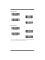
Plug and Play Selections
Note: Plug and Play menu codes will default all settings before programming the
interface.
Industrial Interface: IBM PC
<Factory Default>
IBM PC AT and Compatibles Interface
(also PS/2 30-286, 50, 55SX, 60, 70, 70-061, 70121, 80)
Note: The bar code above also programs a CR (carriage return) suffix.
Industrial Interface, Aux Port: RS-232
RS-232 Interface
Note: The bar code above also programs the following parameters:
Programmable Option Setting
Baud Rate
38,400 bps
Parity
None
Data Format
8 data bits, 1 stop bit
Prefix
None
Suffix
CR
2-2
IBM 468X/9X Ports 5B, 9B, and 17 Interface
Scan one of the following “Plug and Play” codes to program the interface for IBM
4683 Port 5B, 9B, or 17.
Note: When using any of the IBM 4683 interfaces, the maximum allowable data
rate into the base aux port is 9600 baud.
IBM 468X/9X Port 5B Interface
IBM 468X/9X Port 9B HHBCR-1 Interface
IBM 468X/9X Port 9B HHBCR-2 Interface
IBM 468X/9X Port 17 Interface
2-3
Industrial Interface, Aux Port: Wand Emulation
Black High
Wand Emulation (Code 39 Format) Interface
Wand Emulation (Same Code Format) Interface
Supports Code 39, UPC, EAN, Code 128, Interleaved 2 of 5, and Codabar.
All other codes are output as Code 39.
Note: The two bar codes above also program the following parameters:
Programmable Option Setting
Transmission Rate
25 inches per second
Output Polarity
Black High
Industrial Interface, Aux Port: Wand Emulation
White High
Wand Emulation (Code 39 Format) Interface
Wand Emulation (Same Code Format) Interface
Supports Code 39, UPC, EAN, Code 128, Interleaved 2 of 5, and Codabar.
All other codes are output as Code 39.
Note: The two bar codes above also program the following parameters:
Programmable Option Setting
Transmission Rate
25 inches per second
Output Polarity
White High
2-4
Non Decoded Laser Emulation (HHLC)
Use HHLC when connecting to a secondary terminal with integral decoding. This
setting also sets the transmission rate to 37 scans per second and polarity to
white high.
Non Decoded Laser Emulation
2-5
Terminal Interface Selections
If your terminal is not one of the Plug and Play options, you must program your
terminal’s interface using one of the “Terminal I.D.” numbers listed below. To
program your terminal to the scanner, scan the Program Terminal Interface bar
code below, then scan the appropriate Terminal I.D. code and Save from the
Programming Chart on the inside back cover.
Program Terminal Interface
Note: The factory default Terminal I.D. is 003.
Supported Terminals
Terminal
Model(s)
Bull
DEC
DEC
DEC
DEC
DELL
DTK
Falco
Fujitsu
Fujitsu
Fujitsu
HHLC
IBM
IBM
BDS-7 Honeywell (HDS-7)
PC433 SE (Portable PC)
VT-220, 320, 330, 340, 420
VT-510, 520, 525 (PC Style)
VT-510, 520, 525 (DEC Style LK411)
Latitude (Portable PC)
486 SLC (Portable PC)
5220
Point 510
Point 1600
Stylistic (Portable PC)
IBM
IBM
IBM
IBM 102 Key
IBM 122 Key
IBM 122 Key
IDEAssociates
2-6
PC XT
PS/2 25, 30, 77DX2
AT, PS/2 30-286, 50, 55SX, 60, 70,
70-061, 70-121, 80
AT Compatibles Keyboard Emulation
(Non-wedge)
Thinkpad
3151, 3161, 3162, 3163, 3179, 3191,
3192, 3194, 3196, 3197, 3471, 3472,
3476, 3477, 3482, 3486, 3488
3179-1, 3191, 3192, 3471, 3472, 3194
3196, 3197, 3476, 3477, 3482, 3486,
3488
276, 277, 486, 487, 587
Terminal
I.D.
035
003*
004
005
104
003*
003*
047
003*
003*
003*
**
001
002
003
003
003*
006
007
008
071
Supported Terminals (Continued)
Terminal
Model(s)
Lee Data
Link ANSII
Link ASCII
Link Enhanced
PC
Midwest
IIS
MC-3+, MC-5
MC-3+, MC-5
Terminal
I.D.
007
015
014
MC-3+, MC-5
018
Micro Elite TS 30 PS (Portable PC)
003*
Mitak
Olivetti
Olivetti
Relisys
RS-232 Host Port
RS-232 Aux Port
Serial Wedge
Televideo
Texas Instruments
4022 (Portable PC)
M19, M24, M28, M200
M240, M250, M290, M380, P500
TR 175
003*
001
003
003
050
000
050
002
Toshiba
2600 (Portable PC)
003*
Toshiba
Satellite T1960, T2130, CS (Portable PC)
Wand Emulation Code 39 output (via Aux Port)
Wand Emulation Same Code output (via Aux Port)
WYSE
WY-30
WYSE
WY-85/185
WYSE ANSII
WY 60, 120, 150, 160, 325, 370, 99GT
WYSE ASCII
WY 60, 120, 150, 160, 325, 370, 99GT
WYSE Enhanced
WY 60, 120, 150, 160
PC
Zenith
Z-note (Portable PC)
003*
990, 995, 9060
Extensa 560CD (Portable PC)
003*
**
**
013
016
015
014
018
003*
* Emulate External Keyboards and Automatic Direct Connect Mode may also need to
be turned on (see pages 2-9 and 2-11).
** Use Plug and Play Selections on page 2-4.
2-7
Keyboard and Delays Selections
Keyboard Country
This allows you to re-map the keyboard layout for your selected country. As a
general rule, the following characters are not supported by the cordless system
for countries other than the United States:
@ | $ # { } [ ] = / ‘ \ < > ~
*United States
Belgium
Denmark, Finland,
Norway, Sweden
France
Germany, Austria
United Kingdom
Switzerland
Italy
2-8
Keyboard Style Selections
Using the Keyboard Style selections, you can program special keyboard
features, such as Caps Lock and Shift Lock.
Regular is used when you normally have the Caps Lock key off.
Caps Lock is used when you normally have the Caps Lock key on.
Shift Lock is used when you normally have the Shift Lock key on. (Not common
to U.S. keyboards.)
Automatic Caps Lock is used if you change the Caps Lock key on and off. The
software tracks and reflects if you have Caps Lock on or off (AT and PS/2 only).
This selection can only be used with systems that have an LED that notes the
Caps Lock status.
Emulate External Keyboard should be scanned if you do not have an external
keyboard (IBM AT or equivalent).
*Regular
Caps Lock
Shift Lock
Automatic Caps Lock
Emulate External Keyboard
2-9
Keyboard Style Modifiers
This allows you to program special keyboard features, such as CTRL+ codes
and Turbo Mode.
Control + ASCII Mode On: If you scan this selection, the cordless system
sends key combinations for ASCII control characters for values 00-1F. Refer to
page 6-1 for CTRL+ Values.
Control + ASCII Mode On
*Control + ASCII Mode Off
Turbo Mode: Selecting Turbo Mode On, (for the IBM AT only), programs the
cordless system to send characters to the terminal faster.
Turbo Mode On
*Turbo Mode Off
Numeric Keypad Mode: Selecting Numeric Keypad Mode On sends numeric
characters as if entered from a numeric keypad.
Numeric Keypad Mode On
*Numeric Keypad Mode Off
2 - 10
Automatic Direct Connect: When Emulate External Keyboard has been
selected (page 2-9), Automatic Direct Connect Mode keeps the integrated
keyboard from becoming permanently disabled. (This selection disables the
keyboard for the duration of the bar code transmission.)
Automatic Direct Connect Mode On
*Automatic Direct Connect Mode Off
Output Delays Selection
This selection provides control of the time delays between data output by the
cordless system to the host terminal. The actual delay is 5 milliseconds
multiplied by the programmed value (00 - 99). Default = 00.
Intercharacter Delay is the time delay between data characters output by the
cordless system to the host terminal.
Interfunction Delay is the time delay between function (key) codes output by the
cordless system to the host terminal.
Intermessage Delay is the time delay between data messages or records output
by the cordless system to the host terminal.
Example: You need a 45 millisecond delay. Scan the Intercharacter Delay bar
code. Scan “0,” “9,” and Save on the Programming Chart (09 x 5ms = 45ms).
Intercharacter Delay (x5mS)1
Interfunction Delay (x5mS)1
Intermessage Delay (x5mS)1
1. A two-digit number and Save are required after scanning this programming bar code.
Refer to the Programming Chart (inside back cover).
2 - 11
Wand Emulation Selections
Transmission Rate Selection
This programming selection sets the transmission rate from 10 ips (inches per
second) to 300 ips if the cordless system is in Wand Emulation mode.
Programming the transmission rate causes the data to be sent at the specified
rate. The programmed transmission rate must be compatible with the device
receiving the bar code data.
10
*25
40
80
120
150
200
300
2 - 12
Output Polarity Selection
This selection allows you to set the output logic convention for the digital output.
The choices are White High and Black High.
White High
*Black High
2 - 13
Power Settings
Base Low Power Mode
You may want the base unit to draw less power when it is being powered by a
portable data terminal or laptop. Use Base Low Power mode to tell the base to
draw less power.
*Off
On
Note: Using Base Low Power Mode increases latency in radio communications.
2 - 14
Battery Conservation Mode
The scanner offers three low power modes: 1) No timeout, 2) Don’t check base
network before timeout, and 3) Check base network before timeout.
The lowest standby current is achieved with “No timeout” selected. When the
scanner is idle, the standby current is about 15 mA. Radio contact is maintained
and workgroup configuration settings are maintained. “No timeout” is the default
setting and is recommended if the scanner is active for most of the workday and
the charge pack is removed when the scanner is not in use. Alternately, to fully
discharge the battery, leave the charge pack attached and power off the base. If
the scanner goes out of range or the base unit is powered off, the scanner goes
into an active search mode for the base. In this mode, the average current draw
is about 50 mA.
*No Timeout
If “Don’t check base network before timeout” is selected and the scanner is idle,
the standby current is about 20 mA for one timeout period. The standby current
then drops to about 10 mA until the trigger is pulled. The timeout period is
selectable in increments of 15 minutes up to one hour. On the next trigger-pull,
the scanner begins the reassociation process to restore the radio link and the
workgroup configuration settings. This setting is recommended if the scanner is
left inactive for long periods of time during the workday or if the charge pack is
left attached when the scanner is not in use.
Don’t Check for Network Base
Before Timeout
The “Check base network before timeout” mode is identical to the previous mode
except that when the timeout period expires, the scanner tests whether it is still
in radio contact with the base. If radio contact has been lost, the standby current
drops to about 10 mA; otherwise, it remains at 20 mA and the timeout clock
begins another timeout period. This setting may be recommended if the charge
pack is left attached and the base is powered off at the end of each working day.
Check for Network Base
Before Timeout
2 - 15
Timeout Period Selections
Timeout after 15 minutes
Timeout after 30 minutes
Timeout after 45 minutes
*Timeout after 1 hour
2 - 16
Factory Default and Revision Report Selections
Reset Factory Settings
Scanning the Factory Default Settings bar code resets the cordless system to
the original factory settings, clearing any programming changes you may have
made. You may reset the factory default settings for the current application
group or for all application groups.
The Current Application Group Default defaults only the settings described in
Chapter 4 of this manual.
Factory Default Settings: Current Application Group
The ALL Application Groups Default sets the terminal ID to 003, then changes all
settings to factory default values. (See Chapter 10 for a listing of all the factory
defaults.)
Factory Default Settings: ALL Application Groups
Revision Report
Scan the Report Base Software Revision bar code to transmit the cordless base
software revision level to the host terminal. The base software revision will be
printed out as “Base software revision: X.XX, Radio: K.KK.” (The “Xs” and “Ks”
will vary according to the firmware revision.)
Report Base Software Revision
Scan the Report Scanner Software Revision bar code to transmit the cordless
scanner software revision level to the host terminal.
Report Scanner Software Revision
2 - 17
2 - 18
3
Communications Menu
Introduction
Use this section to program the communications parameters for the cordless
system.
This programming section contains the following menu selections:
• Host Port Protocol/Communications (RS-232)
• Auxiliary Port Protocol/Communications (RS-232)
3-1
Host Port Protocol
Default Host Port Protocol
<Default All Host Port RS-232 Protocol>
Baud Rate Selection
This selection sets the baud rate from 300 bits per second to 38,400 bits per
second. Programming baud rate causes the data to be sent at the specified rate.
The host terminal must be set up for the same baud rate as the cordless system
to ensure reliable communication.
300
600
1200
2400
4800
9600
19200
*38400
3-2
Host Port Protocol
Parity Selection
This selection provides a means of checking character bit patterns for validity.
The cordless system can be configured to operate under Even, Odd,
Mark,None, or Space parity options. The host terminal must be set up for the
same parity as the cordless system to ensure reliable communication.
*None
Space
Mark
Even
Odd
Word Length Data Bits Selection
This selection sets the Word Length at seven or eight bits of data per character.
If an application requires only ASCII Hex characters 0 through 7F decimal (text,
digits, and punctuation), select 7 data bits. For applications requiring use of the
full ASCII set, select 8 data bits per character.
7 Data Bits
*8 Data Bits
3-3
Host Port Protocol
Word Length Stop Bits Selection
This selection sets the Word length at one or two stop bits.
*1 Stop Bit
2 Stop Bits
Hardware Flow Control Selection
This selection turns on hardware flow control that checks for a CTS signal before
sending data. This option is useful when your application supports the CTS
signal.
Note: This selection cannot be used with Serial Wedge Output Selection.
On
*Off
3-4
Host Port Communications
Serial Wedge Output Selection
This selection selects the serial output direction required by your application. P1
and P2 are serial wedge designations printed on the serial wedge cable. Usually,
one goes to the host and one goes to the terminal, depending on your specific
application and the serial wedge cable.
To P1
To P1 and P2
To P2
*None (Host Port RS-232)
3-5
Host Port Communications
Host ACK Selection
Some applications require that the host terminal (or server) approve or reject
incoming bar code data and notify the operator of these actions. These
applications require that the host maintain control over the response indicators
emitted from the source scanner. Turning the Host ACK selection on, configures
the cordless system scanners to respond to commands from the host system.
The following criteria must be met for the Host ACK to work correctly:
• The cordless system must be configured for “Host Port RS-232” (Terminal
ID = 050)
• Both the host terminal and the cordless system must have RTS/CTS
handshaking ("Hardware Flow Control Selection" on page 3-4) enabled.
• Host ACK must be enabled (page 3-7).
• System performance degrades when using Host ACK at rates lower than
9600.
• The host terminal software must be capable of interpreting the bar code
data, make decisions based on the data content, and send out appropriate
escape commands to the source scanner.
Escape commands are addressed to the source scanner via “Application Work
Groups.” Once a command is sent, all scanners in a group respond to that
command. Because of this situation, it is recommended that each scanner is
assigned to its own group.
The commands to which the scanner responds are listed on page 3-8 and
page 3-9. The <ESC> is a 1B hex. A typical command string is y <ESC> x,
where “y” is the application work group number, “<ESC> x” is the escape
command, and the comma is the terminator.
Up to twenty commands may be strung together to create custom response
sequences. An example of a command is listed below.
0<ESC>4<ESC>5<ESC>6,
The above example will make a scanner in application work group zero beep low,
medium, high.
Once Host ACK is enabled, the system works as follows:
• The scanner reads a code and sends data to the base/host system. No
audible or visual indication is emitted, unless “Decode Beep” is enabled
(page 3-10). The scanner read indicator goes out upon a successful read.
• Scanner is suspended until 1) a valid escape string is received from the
host system (via the base) or 2) the scanner “times out.”
• Once condition 1 or 2 above has been met, the scanner is ready to scan
again, and the process repeats.
3-6
Host Port Communications
Time out is indicated by three rapid beeps at the same pitch. A time out occurs
if the source scanner does not receive a valid escape command in 10 seconds.
If a time out occurs, the operator should check the host system to understand
why a response to the scanner was not received.
Host ACK Enable
On
*Off
3-7
Host Port Communications
Escape Commands
The tables below list the escape commands that must be generated from the host
system and the resulting action(s).
ST5770 Escape Commands
Command
Action
<ESC> a
Beep (two high tones), illuminate green LED for two seconds
<ESC> b
Beep (three low tones), illuminate green LED nine times
<ESC> 1
Illuminate green LED for 135 milliseconds
<ESC> 2
Illuminate green LED for two seconds
<ESC> 3
Illuminate green LED for five seconds
<ESC> 4
One beep at low volume
<ESC> 5
One beep at medium volume
<ESC> 6
One beep at high volume
<ESC> 7
Beep (one medium tone), illuminate green LED two seconds
<ESC> 8
Beep (three low tones), illuminate green LED nine times
3-8
Host Port Communications
IT3870 Escape Commands
Command
Action
<ESC> a
Indicate as if successful menu change made
<ESC> b
Indicate as if unsuccessful menu change made
<ESC> 1
Illuminate green LED for 135 milliseconds (followed by at least 70 mSecs.
dark time when multiple blinks)
<ESC> 2
Illuminate green LED for two seconds (followed by at least 500 mSecs.
dark time when multiple blinks)
<ESC> 3
Illuminate green LED for five seconds (followed by at least 500 mSecs.
dark time when multiple blinks)
<ESC> 4
One beep at low volume
<ESC> 5
One beep at medium volume
<ESC> 6
One beep at high volume
<ESC> 7
Indicate as successful decode and communication to host.
<ESC> 8
Indicate as unsuccessful decode and communication to host.
3-9
Host Port Communications
Decode Beep Selection
Note: Decode Beep mode is active only when the programming selections Host
ACK (page 3-6) or Data Format Required (page 4-19) are turned on.
When Host ACK Selection is on, the scanner will only beep/blink in response to
the Escape commands generated by the host. Should you also want the scanner
to beep when a bar code has been successfully decoded and successfully
communicated to the base, turn the Decode Beep Selection on.
When Data Format Required is on, the scanner will only beep if the input data
conforms to the edited format or triple beep if it does not meet the format
requirements. Should you also want the scanner to beep when a bar code has
been successfully read and sent to the host from the base, turn on the Decode
Beep Selection.
On
*Off
3 - 10
Auxiliary Port Input Protocol
Default Auxiliary Port Protocol
<Default All Auxiliary Port Protocol>
Baud Rate Selection
This selection sets the baud rate from 300 bits per second to 38,400 bits per
second. Programming baud rate causes the data to be sent at the specified rate.
The device connected to the Auxiliary Port must be set up for the same baud rate
as the Aux Port to ensure reliable communication.
300
600
1200
2400
4800
9600
19200
*38400
3 - 11
Auxiliary Port Input Protocol
Parity Selection
This selection provides a means of checking character bit patterns for validity.
The Auxiliary Port can be configured to operate under Even, Odd, Mark, None,
or Space parity options. The device connected to the Auxiliary Port must be set
up for the same parity as the Aux Port to ensure reliable communication.
*None
Space
Mark
Even
Odd
Word Length Data Bits Selection
This selection sets the Word Length at seven or eight bits of data per character.
If an application requires only ASCII Hex characters 0 through 7F decimal (text,
digits, and punctuation), select 7 data bits. For applications requiring use of the
full ASCII set, select 8 data bits per character.
7 Data Bits
*8 Data Bits
3 - 12
Auxiliary Port Input Protocol
Word Length Stop Bits Selection
This selection sets the Word Length at one or two stop bits.
*1 Stop Bits
2 Stop Bits
Hardware Flow Control Selection
This selection turns on hardware flow control that checks for a CTS signal before
sending data. This option is useful when your application supports the CTS
signal.
On
*Off
Note: The Auxiliary Port receive function will only work properly if RTS/CTS or
ACK/NAK flow control is used. If your host system does not support RTS/
CTS or ACK/NAK handshaking, some or all of your data will be lost.
3 - 13
Auxiliary Port Input Communications
IBM 4683 Async Address Selections
If you are going to program the interface for IBM 4683 Async Addresses, you
must first program the Terminal ID as 51 (see page 2-6). Then, scan one of the
programming codes below for your 4683 Async Address selection.
Note: When using any of the IBM 4683 interfaces, the maximum allowable data
rate into the base aux port is 9600 baud.
Address $68
(Socket 23: 2A Left)
Address $69
(Socket 23: 2B Right)
Address $64
(Socket 25: 2A Left)
Address $65
(Socket 25: 2B Right)
Aux Port Disable
3 - 14
Auxiliary Port Input Communications
Protocol Selection
This selection programs the Auxiliary Port for the protocol required by the input
device to the Auxiliary Port. The protocol is a set of rules concerning the
exchange of data between serially communicating devices. The Auxiliary Port
supports Record, Burst, and ACK/NAK protocols when receiving data from an
RS-232 device.
When the Aux Port is being used as an input, data packets can be sent from the
peripheral to the Aux Port in two different forms (See "Data Character
Selection" on page 3-16).
• Record -- a single string of data that is to be sent to the host system.
• Block -- several strings of data that are to be appended together within
the base and sent to the host system as a single message.
The programmer should determine which of the four selections below best
meets the requirements of the peripheral.
• Record -- used when the transmitting peripheral is sending messages
when no confirmation of receipt is required.
• Record ACK/NAK -- same as Record, however the base responds to the
peripheral upon receipt of the message. The <ACK> (acknowledge)
character (ASCII 06 hex) is sent to the peripheral to acknowledge that a
<NAK> (non-acknowledge) character (ASCII 15 hex) is sent when the
message is not received correctly.
• Block ACK/NAK -- same as Record ACK/NAK, but the <ACK> or <NAK>
is issued upon completion of the block message.
• Burst -- used when XON/XOFF software flow control is required by the
transmitting peripheral.
*Record
Burst
Record ACK/NAK
Block ACK/NAK
3 - 15
Auxiliary Port Input Communications
Data Character Selection
This selection selects the serial output data characters that may be sent from the
RS-232 device connected to the Auxiliary Port.
When the Aux Port is used as an input, it is recommended (although not required)
that incoming messages be “framed” by start and stop characters. These
framing characters indicate to the base the beginning and end of a message.
The use of these characters decreases the possibility of missing or partial
messages being sent to the host system.
Note: These characters are stripped from the message within the base and are
not sent to the host system.
The bar codes below are used to configure the base to conform to the specific
framing characters sent from the peripheral device.
• SOR -- used to program the starting frame character of a “record”
• EOR -- used to program the ending frame character of a “record”
• SOB -- used to program the starting frame character of a “block”
• EOB -- used to program the ending frame character of a “block”
Default SOR Character = none (NUL: 00).
Default EOR Character = Carriage Return (CR: 0D).
Default SOB Character = none (NUL: 00).
Default EOB Character = End of Text (EOT: 04).
SOR (Start of Record)1
EOR (End of Record)1
SOB (Start of Block)1
EOB (End of Block)1
1. A two-digit number and Save are required after scanning this programming bar code. Refer to the Programming Chart (inside back cover).
3 - 16
Auxiliary Port Input Communications
Aux Prefix/Suffix Selections
Aux Prefix and Suffix
Aux Prefix and Suffix characters are data characters you may assign to incoming
Auxiliary Port data.
Data frame
Prefix
Message
Suffix
Characters for the Prefix and Suffix are selected by their hexadecimal ASCII
value, up to 12 characters each. Prefix and Suffix characters may be assigned
to all incoming data.
Default Prefix (incoming data) = none.
Default Suffix (incoming data) = none.
Default Prefix (outgoing data) = none.
Default Suffix (outgoing data) = Carriage Return (CR).
Programming Steps to Add an Aux Prefix / Suffix to Incoming Data:
Step 1. To add a Prefix, scan the Add Aux Prefix programming bar code.
To add a Suffix, scan the Add Aux Suffix programming bar code.
Step 2. Scan two bar codes for the Hex Value “72” (“r,” which represents the
identifier for the Aux Port). Scan the two digits on the Programming
Chart (on the inside back cover of this manual).
Step 3. Refer to the Hex ASCII Chart(page 3-19) to find the Hex value that
represents the ASCII characters you wish to attach to the data. Use
the Programming Chart (inside back cover) to scan the alphanumeric
combination that represents the ASCII characters.
Step 4. To complete Aux Prefix / Suffix programming, scan either:
Save - This exits, saving the Prefix / Suffix selections you just
assigned.
Discard - This exits without changing the Prefix / Suffix.
Other Programming Selections: Scanning the Default Prefix or Default Suffix
bar code sets the default Prefix or Suffix (shown above).
Scanning the Clear All Prefixes or Clear All Suffixes bar code deletes all Prefix
or Suffix selections.
If you want to turn off the prefix or suffix formatting for a period of time, scan
Disable Aux Prefix/Suffix. To turn back on, scan Enable Aux Prefix/Suffix.
Note: Aux Prefix / Suffix programming examples may be found on page 3-18.
3 - 17
Auxiliary Port Input Communications
Aux Prefix and Suffix Examples
Example 1: Add a Prefix
To add an HT (tab) Prefix to incoming data:
Step 1. Scan the Add Aux Prefix Prefix Selection bar code.
Step 2. Scan 7 and 2 on the Programming Chart (inside back cover).
Step 3. An “HT” is equivalent to “09” (see the Hex ASCII Chart). Scan 0 and 9
on the Programming Chart.
Step 4. Scan Save.
Example 2: Add a Suffix
To add a CR (carriage return) Suffix to incoming data:
Step 1. Scan the Add Aux Suffix Suffix Selection bar code.
Step 2. Scan 7 and 2 on the Programming Chart (inside back cover).
Step 3. A “CR” is equivalent to “0D” (see the Hex ASCII Chart). Scan 0 and D
on the Programming Chart.
Step 4. Scan Save.
Note: If the Aux Port ID is required in conjunction too other prefixes, scan 5 C 8 0.
Note: To program a backslash (\), scan 5 C 5 C.
3 - 18
Auxiliary Port Input Communications
Decimal to Hex to ASCII Conversion Chart
Dec.
Hex
ASCII
Dec.
Hex
ASCII
Dec.
Hex
ASCII
Dec.
Hex
ASCII
0
1
2
3
4
5
6
7
8
9
10
11
12
13
14
15
16
17
18
19
20
21
22
23
24
25
26
27
28
29
30
31
00
01
02
03
04
05
06
07
08
09
0A
0B
0C
0D
0E
0F
10
11
12
13
14
15
16
17
18
19
1A
1B
1C
1D
1E
1F
NUL
SOH
STX
ETX
EOT
ENQ
ACK
BEL
BS
HT
LF
VT
FF
CR
SO
SI
DLE
DC1
DC2
DC3
DC4
NAK
SYN
ETB
CAN
EM
SUB
ESC
FS
GS
RS
US
32
33
34
35
36
37
38
39
40
41
42
43
44
45
46
47
48
49
50
51
52
53
54
55
56
57
58
59
60
61
62
63
20
21
22
23
24
25
26
27
28
29
2A
2B
2C
2D
2E
2F
30
31
32
33
34
35
36
37
38
39
3A
3B
3C
3D
3E
3F
SP
!
“
#
$
%
&
‘
(
)
*
+
,
.
/
0
1
2
3
4
5
6
7
8
9
:
;
<
=
>
?
64
65
66
67
68
69
70
71
72
73
74
75
76
77
78
79
80
81
82
83
84
85
86
87
88
89
90
91
92
93
94
95
40
41
42
43
44
45
46
47
48
49
4A
4B
4C
4D
4E
4F
50
51
52
53
54
55
56
57
58
59
5A
5B
5C
5D
5E
5F
@
A
b
C
D
E
F
G
H
l
J
K
L
M
N
O
P
Q
R
S
T
U
V
W
X
Y
Z
[
\
]
^
_
96
97
98
99
100
101
102
103
104
105
106
107
108
109
110
111
112
113
114
115
116
117
118
119
120
121
122
123
124
125
126
127
60
61
62
63
64
65
66
67
68
69
6A
6B
6C
6D
6E
6F
70
71
72
73
74
75
76
77
78
79
7A
7B
7C
7D
7E
7F
‘
a
b
c
d
e
f
g
h
i
j
k
l
m
n
o
p
q
r
s
t
u
v
w
x
y
z
{
|
}
~
DEL
3 - 19
Auxiliary Port Input Communications
Aux Prefix Selection
Add Aux Prefix1
Default Aux Prefix (none)
Clear All Aux Prefixes
Aux Suffix Selection
Add Aux Suffix1
Default Aux Suffix (CR)
Clear All Aux Suffixes
1. One or more two-digit numbers and Save are required after scanning this programming
bar code. Refer to the Programming Chart (inside back cover).
Exit Selection for Aux Prefix / Suffix
Save
Discard
3 - 20
Auxiliary Port Input Communications
Aux Prefix On/Off
The following selections allow you to turn on and off the Aux Prefix and Suffix
formatting. These codes are used when you want to toggle between turning on
and off the prefix and/or suffix formatting.
*On
Off
Aux Suffix On/Off
*On
Off
Aux Port I.D. Transmit Selection
This will attach the Aux Port identifier (which is the letter “r”) to the incoming data
at the Auxiliary Port and will send it along with the data to the host device.
On
*Off
3 - 21
Auxiliary Port Input Communications
Aux Data Format Editor Selections
The Aux Data Format Editor selections are used to edit incoming data to the aux
port. For example, you can use the Aux Data Format Editor to insert characters
at certain points in bar code data as it is scanned.
It is not necessary to use the Aux Data Format Editor. A set of defaults for the
aux data format is already programmed in the base. The selections in the
following pages are used only if you wish to alter the default settings. Default Aux
Data Format setting = none.
If you have changed aux data format settings, and wish to clear all formats and
return to the defaults, scan the Default Aux Data Format code.
To Add an Aux Data Format
Step 1. Scan the Enter Aux Data Format symbol (page 3-26).
Step 2. Primary/Alternate Format
Determine if this will be your primary aux data format, or one of 3
alternate formats. (Alternate formats allow you “single shot” capability
to scan one bar code using a different aux data format. After the one
bar code has been read, the scanner reverts to the primary aux data
format. See page 3-27.) If you are programming the primary format,
scan 0. If you are programming an alternate format, scan 1, 2, or 3,
depending on the alternate format you are programming.
Step 3. Terminal Type
Refer to the Supported Terminals Chart (page 2-6) and locate the
Terminal ID number for your PC. Scan 3 numeric bar codes on the
inside back cover to program the scanner for your terminal ID (you must
enter 3 digits). For example, scan 0 0 3 for an IBM AT.
Note: To apply a format to all terminal types, a universal code of 099 is used.
Step 4. Code I.D.
Scan 7 then 2 from the Programming Chart. (This is the hex value for
“r,” the aux port I.D.)
Step 5. Length
Specify what length (up to 9999 characters) of data will be acceptable
for this symbology. Scan the 4 digit data length from the Programming
Chart. (Note: 50 characters is entered as 0050. 9999 is a universal
number, indicating all lengths.)
3 - 22
Auxiliary Port Input Communications
Step 6. Editor Commands
Refer to the Format Editor Commands (page 3-24). Scan the symbols
that represent the command you want to enter. 94 alphanumeric
characters may be entered for each symbology data format.
Step 7. Scan Save to save your entries.
Other Programming Selections
• Clear One Aux Data Format
This deletes one aux data format for one symbology. If you are clearing
the primary aux format, scan 0. If you are clearing an alternate format,
scan 1, 2, or 3, depending on the alternate format you are clearing. Scan
the Terminal Type (refer to the Supported Terminals Chart on page 2-6),
then 7, 2 (for the aux port I.D.), and the length of the format you want to
delete. That length aux data format for that symbology is deleted and all
other formats are unaffected.
• Save
This exits, saving any Aux Data Format changes.
• Discard
This exits without saving any Aux Data Format changes.
Aux Data Formatter Example
Five digit data is sent to the Auxiliary Port, however the host system can only
accept eight digit data. Three zeroes must be added to the beginning of the Aux
Port data.
Received
12345
Must send
00012345
Refer to the Aux Format Editor Commands on page 3-24 to format the following
example. The programming bar codes on page 3-26 and the alphanumeric bar
codes on the inside back cover are used to program the aux data formatter.
• Scan the Enter Aux Data Format bar code (page 3-26).
• Scan 0 (primary) or 1 or 2 or 3 (for alternates).
• Scan 0 9 9 (all terminal types).
• Scan 7 2 (the hex value for the aux port).
• Scan 0 0 0 5 (the data length).
3 - 23
Auxiliary Port Input Communications
The Aux Data Editor Commands are:
• Scan F 4 (see page 3-24 for a description).
• Scan 3 0 (hex value for 0).
• Scan 0 3 (indicating the 0 should be sent 3 times).
• Scan F 1 to send the data, then 0 0 (the hex value for NUL).
• Scan Save to end the Aux Data Formatting.
Aux Format Editor Commands
Send Commands
F1 Send all characters followed by “xx” key or function code, starting from current cursor position. Syntax = F1xx (xx stands for the hex value for an
ASCII code, see Hex to ASCII Conversion chart, page 3-19.)
F2 Send “nn” characters followed by “xx” key or function code, starting from
current cursor position. Syntax = F2nnxx (nn stands for the numeric value
(00-99) for the number of characters and xx stands for the hex value for an
ASCII code. See Hex to ASCII Conversion chart, page 3-19.)
F3 Send up to but not including “ss” character (Search and Send) starting from
current cursor position, leaving cursor pointing to “ss” character followed by
“xx” key or function code. Syntax = F3ssxx (ss and xx both stand for the
hex values for ASCII codes, see Hex to ASCII Conversion chart, page 319.)
F4 Send “xx” character “nn” times (Insert) leaving cursor in current cursor position. Syntax = F4xxnn (xx stands for the hex value for an ASCII code, see
Hex to ASCII Conversion chart, page 3-19, and nn is the numeric value (0099) for the number of times it should be sent.)
E9 Send all but the last “nn” characters, starting from the current cursor position. Syntax = E9nn (nn is the numeric value (00-99) for the number of
characters that will not be sent at the end of the message.)
Move Commands
F5 Move the cursor ahead “nn” characters from current cursor position.
Syntax = F5nn (nn stands for the numeric value (00-99) for the number of
characters the cursor should be moved ahead.)
F6 Move the cursor back “nn” characters from current cursor position.
Syntax = F6nn (nn stands for the numeric value (00-99) for the number of
characters the cursor should be moved back.)
F7 Move the cursor to the beginning of the data string. Syntax = F7.
EA Move the cursor to the end of the data string. Syntax = EA.
Search Commands
F8 Search ahead for “xx” character from current cursor position, leaving cursor
pointing to “xx” character. Syntax = F8xx (xx stands for the hex value for an
ASCII code, see Hex to ASCII Conversion chart, page 3-19.)
3 - 24
Auxiliary Port Input Communications
F9 Search back for “xx” character from current cursor position, leaving cursor
pointing to “xx” character. Syntax = F9xx (xx stands for the hex value for
an ASCII code, see Hex to ASCII Conversion chart, page 3-19.)
E6 Search ahead for the last instance of “xx” character from the current cursor
position, then increment cursor. Syntax = E6xx (xx stands for the hex
value for an ASCII code, see Hex to ASCII Conversion chart, page 3-19.)
E7 Search back for the last instance of “xx” character from the current cursor
position, then increment cursor. Syntax = E7xx (xx stands for the hex
value for an ASCII code, see Hex to ASCII Conversion chart, page 3-19.)
Miscellaneous Commands
FB Suppress all occurrences of up to 15 different characters, starting at the
current cursor position, as the cursor is advanced by other commands.
When the FC command is encountered, the suppress function is terminated. The cursor is not moved by the FB command. Syntax = FBnnxxyy .
.zz where nn is a count of the number suppress characters in the list and
xxyy .. zz is the list of characters to be suppressed. (xx stands for the hex
value for an ASCII code, see Hex to ASCII Conversion chart, page 3-19.)
FC Disable suppress filter and clear all suppressed characters. Syntax = FC.
E4 Replaces up to 15 characters in the data string with user specified characters. Replacement continues until the E5 command is encountered. Syntax
= E4nnxx1xx2yy1yy2...zz1zz2 where nn is the total count of both characters to be replaced plus replacement characters; xx1 defines characters to
be replaced and xx2 defines replacement characters, continuing through
zz1 and zz2.
E5 Terminates character replacement. Syntax = E5.
FE Compare character in current cursor position to the character “xx.” If characters are equal, increment cursor. If characters are not equal, no format
match. Syntax = FExx (xx stands for the hex value for an ASCII code, see
Hex to ASCII Conversion chart, page 3-19.)
EC Check to make sure there is a numeric character at the current cursor position. If character is not numeric, format is aborted. Syntax = EC.
ED Check to make sure there is a non-numeric character at the current cursor
position. If character is numeric, format is aborted. Syntax = ED.
EF Inserts a delay of up to 49,995 milliseconds (in multiples of 5). Syntax =
EFnn where nn is a count of the number 5 ms delays, up to 9,999.
3 - 25
Auxiliary Port Input Communications
Aux Data Format Editor
See through page 3-22 through page 3-25 for a description of Aux Data Format
selections and commands.
Enter Aux Format
Default Aux Data Format
Clear One Aux Data Format
Clear All Aux Data Formats
Save Current Changes
Discard Current Changes
Aux Data Formatter
When Aux Data Formatter is turned off, the data coming in to the aux port is
output to the host as received (including prefixes and suffixes).
*Aux Data Formatter On
Aux Data Formatter Off
3 - 26
Auxiliary Port Input Communications
Require Aux Data Format
When Aux Data Formatter is required, all incoming data must conform to an
edited format or the base does not transmit the input data to the host device. If
this occurs, the data is discarded. Default = Not Required.
Aux Data Format Required
*Aux Data Format Not
Required
Alternate Aux Data Formats
Alternate formats allow you “single shot” capability to edit incoming data using a
different aux data format than your primary aux format. When aux data formats
are programmed (see page 3-17), you must input whether you are programming
the primary aux format, or an alternate format numbered 1, 2, or 3.
An alternate aux format is initiated by scanning one of the 3 alternate aux format
bar codes below. The base will edit the incoming data, formatting the data with
the selected alternate aux format, then revert immediately to the primary aux
format.
Alternate Aux Data Format 1
Alternate Aux Data Format 2
Alternate Aux Data Format 3
3 - 27
3 - 28
4
Application Work Group Menu
Introduction
Use this section to program parameters for application work groups for the
cordless system.
This programming section contains the following menu selections:
• Output Selections (User Feedback)
• Prefix and Suffix
• Data Formatter
Each cordless scanner can be assigned to one of nine application work groups.
Each work group may be set up in a different configuration using the
programming selections found in this section of the manual. For example, one
group may need the beeper turned off, will only scan Code 39 bar codes, and
needs a carriage return suffix added to the data being sent to the host system via
the base. Another group may require that scanner voting be turned on, will scan
UPC A, and needs a space added to the transmitted data, between the main
UPC bar code data and the five digit addenda.
The Application Work Groups Selection (on the next page) sets up the scanner
according to one of the application work group(s). After you’ve scanned the
association bar code on the base, scan one of the work group numbers to assign
the cordless scanner to a specific group. The scanner then receives all of the
corresponding parameters from the base unit. You may then alter the
parameters your application requires from the Output (User Feedback), Prefix
and Suffix, Data Formatter Selections, and symbology menu pages.
To add a new cordless scanner to an established group, associate the scanner
to the base and scan the application work group number. The scanner will
automatically reconfigure to operate and send data to the host system according
to that group’s programmed selections. Any programming selections you
change or make with one cordless scanner will affect all the scanners in the
same work group.
Note: To program a group’s parameters, you must first scan the group number
and then the programming selections (prefix, suffix, data formatter, etc.).
The parameters can’t be programmed first and then “made” a group by
scanning an application work group number.
To remove a scanner associated with a base unit, use the Remove Scanner
Selection on page 4-3. For instance, if nine scanners are associated with a base
(the maximum number) and you want to add a new scanner, you will need to
remove one scanner from the network. After removing one scanner by using the
Remove Scanner programming bar code, add the new scanner by scanning the
association bar code on the base unit.
4-1
Output Selections
Application Work Group Selection
This programming selection sets up application work groups sharing specific
programming settings (such as Beeper Volume, Scanner Voting, Prefix / Suffix,
and Data Formatter). Scan the group number and then program the selections
your application requires. (Refer to the introduction, page 4-1, for more
information on application work groups.)
* Group 0
Group 1
Group 2
Group 3
Group 4
Group 5
Group 6
Group 7
Group 8
4-2
Remove Scanner Selection
This programming selection removes a scanner from an associated base unit.
Remove Scanner
Beeper Volume Selection
Off
Low
Medium
*High
4-3
Beeper Pitch
You may wish to set your beeper to a higher or lower pitch. This feature is helpful
if there are several scanners being used in close proximity. Different pitches
make it easier to distinguish which scanner is beeping.
Low
*Medium
Medium High
High
Scanner Voting Selection
The scanner offers three levels of voting for decoded messages: off, normal, and
high. The greatest decoding speed is achieved by turning voting off. The
greatest level of security is achieved by selecting the high voting level. The high
voting level is the recommended setting when reading poor quality bar codes.
The normal voting level provides a balance of good decoding speed and security.
Regardless of voting level selection, the decoded message format and length
may be qualified before the message is transmitted. This will provide additional
security. If format and length requirements are not met, the message will not be
transmitted. Refer to Data Formatter Selections (page 4-15) to set format
requirements. Refer to Chapter 5 to set message length requirements, by
symbology.
Note: To maximize both decoding speed and security, it is recommended to
disable all symbologies that will not be used.
When voting is turned off, a bar code needs only to be read one time for a
decode.
Off
4-4
When the normal voting level is selected, a bar code needs to be read multiple
times for a decode. The number of votes depends on the symbology and the
message length. Since greater security is appropriate for shorter messages,
short messages require more votes than long messages.
*Voting Normal
The high voting level works much like the normal level, except that short
messages require twice as many votes. Note that for the ST5770, the high level
works identical to the normal level.
Voting High
Laser Marker Beam (ST5770 only)
When this selection is turned on (short or long duration), the cordless scanner
shows a marker or locator beam before the red scan line opens across a bar
code and the scanning process begins. The marker beam, emitted by centering
the optical scan mirror, appears as a bright spot of illumination that serves as an
aiming guide when bar code targets are at a distance from the scanner.
Note: If this selection is turned on, scanning is delayed for 0.5 or 1.2 seconds
while the marker beam is enabled.
*Off
Short Duration (.5 seconds)
Long Duration (1.2 seconds)
4-5
AIM I.D. Prefix
This selection allows you to turn on or off the transmission of an Aim I.D. before
the decoded symbology. (See the Symbology Chart below for the single AIM
character code that identifies each symbology.) When you scan the On code, all
current prefixes are cleared, then an AIM I.D. for all symbologies is programmed.
On
*Off
Code I.D. Prefix
This selection allows you to turn on or off the transmission of a Code I.D. before
the decoded symbology. (See the Symbology Chart below for the single
character code that identifies each symbology.) When you scan the On code, all
current prefixes are cleared, then a Code I.D. for all symbologies is programmed.
On
*Off
4-6
Symbology Chart
Symbology
AIM
ID
Code
ID
Symbology
AIM
ID
Code
ID
Codabar
]Fm
a
Code 128
]Cm
j
Code 39
]Am
b
Matrix 2 of 5
]Xm
m
UPC
]Em
c
Telepen
]Bm
t
EAN
]Em
d
PDF417
]Lm
r
Interleaved 2 of 5
]Im
e
MicroPDF417
]Lm
R
Code 2 of 5, IATA
(with 2-bar start/
stop patterns)
]Rm
f
Reduced Space
Symbology (RSS)
]em
y
Code 2 of 5, Industrial (with 3-bar
start/stop patterns)
]Sm
f
]em
y
Code 11
]Hm
h
]Xm
q
Code 93
]Gm
i
EAN•UCC Composite
China Post Code
Note: where m represents the AIM modifier character, see AIM International
Technical Specification - Symbology Identifiers
4-7
Prefix/Suffix Selections
When a bar code is scanned, additional information is sent to the host computer
along with the bar code data. This group of bar code data and additional,
user-defined data is called a “message string.” The selections in this section are
used to build the user-defined data into the message string.
Prefix and Suffix characters are data characters that can be sent before and after
scanned data. You can specify if they should be sent with all symbologies, or
only with specific symbologies. The following illustration shows the breakdown
of a message string:
Prefix
1-12
alphanumeric
characters
Scanned Data
variable
length
Suffix
1-12
alphanumeric
characters
Points to Keep In Mind
• It is not necessary to customize the message string. The selections in this
chapter are only used if you wish to alter the default settings. Default
prefix = None. Default suffix = CR.
• If desired, each decoded symbology may be assigned a unique prefix and
suffix.
• You can add any prefix or suffix from the ASCII chart (page 4-14), plus
Code I.D. and Aim I.D.
• You can string together several entries for several symbologies at one
time.
• Enter prefixes and suffixes in the order in which you want them to appear
on the output.
4-8
To Add a Prefix or Suffix:
Step 1. Scan the Add Prefix (page 4-11) or Add Suffix symbol (page 4-11).
Step 2. Determine the 2 digit Hex value from the Symbology Chart (page 4-12)
for the symbology to which you want to apply the prefix or suffix.
Step 3. Scan the 2 hex digits from the Programming Chart inside the back
cover or scan 9, 9 for all symbologies.
Step 4. Determine the hex value from the Decimal to Hex to ASCII Conversion
Chart (page 4-14) for the prefix or suffix you wish to enter.
Step 5. Scan the 2 digit hex value from the Programming Chart inside the back
cover.
Step 6. Repeat Steps 4 and 5 for every prefix or suffix character.
Step 7. To add the Code I.D., scan 5, C, 8, 0.
To add AIM I.D., scan 5, C, 8, 1.
To add a backslash (\), scan 5, C, 5, C.
Step 8. Scan Save to exit and save, or scan Discard to exit without saving.
Repeat Steps 1-6 to add a prefix or suffix for another symbology.
Example: Add a Suffix to a specific symbology
To send a CR (carriage return)Suffix for UPC only:
Step 1. Scan Add Suffix.
Step 2. Determine the 2 digit hex value from the Symbology Chart (page 4-12)
for UPC.
Step 3. Scan 6, 3 from the Programming Chart (inside back cover).
Step 4. Determine the hex value from the Decimal to Hex to ASCII Conversion
Chart (page 4-14) for the CR (carriage return).
Step 5. Scan 0, D from the Programming Chart (inside back cover).
Step 6. Scan Save, or scan Discard to exit without saving.
4-9
To Clear One or All Prefixes or Suffixes:
You can clear a single prefix or suffix, or clear all prefixes/suffixes for a
symbology. When you Clear One Prefix (Suffix), the specific character you
select is deleted from the symbology you want. When you Clear All Prefixes
(Suffixes), all the prefixes or suffixes for a symbology are deleted.
Step 1. Scan the Clear One Prefix or Clear One Suffix symbol.
Step 2. Determine the 2 digit Hex value from the Symbology Chart (page 4-12)
for the symbology from which you want to clear the prefix or suffix.
Step 3. Scan the 2 digit hex value from the Programming Chart inside the back
cover or scan 9, 9 for all symbologies.
Your change is automatically saved.
4 - 10
Prefix Selections
Add Prefix1
Default Prefix (none)
Clear One Prefix1
Clear All Prefixes
Suffix Selections
Add Suffix1
Default Suffix (CR)
Clear One Suffix1
Clear All Suffixes
1. One or more two-digit numbers and Save are required after scanning this programming
bar code. Refer to the Programming Chart (inside back cover).
4 - 11
Exit Selection for Prefix/Suffix
Save
Discard
Symbology Chart
Symbology
Code Hex
ID
ID
Symbology
Code
ID
Hex
ID
Codabar
a
61
Code 128
j
6A
Code 39
b
62
Matrix 2 of 5
m
6D
UPC
c
63
Telepen
t
74
EAN
d
64
PDF417
r
72
Interleaved 2 of 5
e
65
MicroPDF417
R
52
Code 2 of 5, IATA (with 2bar start/stop patterns)
f
66
y
79
Code 2 of 5, Industrial
(with 3-bar start/stop patterns)
f
66
y
79
Code 11
h
68
China Post Code
q
71
Code 93
i
69
All Symbologies1
Reduced Space Symbology (RSS)
EAN•UCC Composite
99
1.Prefix/Suffix Programming only!
Note: Prefix/Suffix entries for specific symbologies override the universal (All
Symbologies, 99) entry.
4 - 12
Work Group Prefix On/Off
The following selections allow you to turn on and off the prefix and suffix
formatting. These codes are used when you want to toggle between turning on
and off the prefix and suffix formatting.
*On
Off
Suffix On/Off
*On
Off
4 - 13
Decimal to Hex to ASCII Conversion Chart
Dec.
Hex
ASCII
Dec.
Hex
ASCII
Dec.
Hex
ASCII
Dec.
Hex
ASCII
0
1
2
3
4
5
6
7
8
9
10
11
12
13
14
15
16
17
18
19
20
21
22
23
24
25
26
27
28
29
30
31
00
01
02
03
04
05
06
07
08
09
0A
0B
0C
0D
0E
0F
10
11
12
13
14
15
16
17
18
19
1A
1B
1C
1D
1E
1F
NUL
SOH
STX
ETX
EOT
ENQ
ACK
BEL
BS
HT
LF
VT
FF
CR
SO
SI
DLE
DC1
DC2
DC3
DC4
NAK
SYN
ETB
CAN
EM
SUB
ESC
FS
GS
RS
US
32
33
34
35
36
37
38
39
40
41
42
43
44
45
46
47
48
49
50
51
52
53
54
55
56
57
58
59
60
61
62
63
20
21
22
23
24
25
26
27
28
29
2A
2B
2C
2D
2E
2F
30
31
32
33
34
35
36
37
38
39
3A
3B
3C
3D
3E
3F
SP
!
“
#
$
%
&
‘
(
)
*
+
,
.
/
0
1
2
3
4
5
6
7
8
9
:
;
<
=
>
?
64
65
66
67
68
69
70
71
72
73
74
75
76
77
78
79
80
81
82
83
84
85
86
87
88
89
90
91
92
93
94
95
40
41
42
43
44
45
46
47
48
49
4A
4B
4C
4D
4E
4F
50
51
52
53
54
55
56
57
58
59
5A
5B
5C
5D
5E
5F
@
A
b
C
D
E
F
G
H
l
J
K
L
M
N
O
P
Q
R
S
T
U
V
W
X
Y
Z
[
\
]
^
_
96
97
98
99
100
101
102
103
104
105
106
107
108
109
110
111
112
113
114
115
116
117
118
119
120
121
122
123
124
125
126
127
60
61
62
63
64
65
66
67
68
69
6A
6B
6C
6D
6E
6F
70
71
72
73
74
75
76
77
78
79
7A
7B
7C
7D
7E
7F
‘
a
b
c
d
e
f
g
h
i
j
k
l
m
n
o
p
q
r
s
t
u
v
w
x
y
z
{
|
}
~
DEL
4 - 14
Data Formatter Selections
The Data Format Editor selections are used to edit scanned data. For example,
you can use the Data Format Editor to insert characters at certain points in bar
code data as it is scanned.It is not necessary to use the Data Format Editor. A
set of defaults for the data format is already programmed in the scanner. The
selections in the following pages are used only if you wish to alter the default
settings. Default Data Format setting = none.
If you have changed data format settings, and wish to clear all formats and return
to the defaults, scan the Default Data Format code on page 4-18.
To Add a Data Format
Step 1. Scan the Enter Data Format symbol (page 4-18).
Step 2. Primary/Alternate Format
Determine if this will be your primary data format, or one of 3 alternate
formats. (Alternate formats allow you “single shot” capability to scan
one bar code using a different data format. After the one bar code has
been read, the scanner reverts to the primary data format. See page 420.) If you are programming the primary format, scan 0. If you are programming an alternate format, scan 1, 2, or 3, depending on the alternate format you are programming.
Step 3. Terminal Type
Refer to the Supported Terminals Chart (page 2-6) and locate the Terminal ID number for your PC. Scan 3 numeric bar codes on the inside
back cover to program the scanner for your terminal ID (you must enter
3 digits). For example, scan 0 0 3 for an AT wedge.
Note: The wildcard for all terminal types is 099.
Step 4. Code I.D.
On page 4-12, find the symbology to which you want to apply the data
format. Locate the Hex value for that symbology and scan the 2 digit
hex value from the Programming Chart.
Step 5. Length
Specify what length (up to 9999 characters) of data will be acceptable
for this symbology. Scan the four digit data length from the Programming Chart. (Note: 50 characters is entered as 0050. 9999 is a universal number, indicating all lengths.)
Step 6. Editor Commands
Refer to the Format Editor Commands Chart (page 4-16). Scan the
symbols that represent the command you want to enter. 94 alphanumeric characters may be entered for each symbology data format.
Step 7. Scan Save to save your entries.
4 - 15
Other Programming Selections
•
Clear One Data Format
This deletes one data format for one symbology. If you are clearing the
primary format, scan 0. If you are clearing an alternate format, scan 1, 2, or
3, depending on the alternate format you are clearing. Scan the Terminal
Type (refer to the Supported Terminals Chart on page 2-6), Code I.D. and the
length of the format you want to delete. That length data format for that
symbology is deleted and all other formats are unaffected.
•
Save
This exits, saving any Data Format changes.
•
Discard
This exits without saving any Data Format changes.
Data Format Editor Commands
Send Commands
F1 Send all characters followed by “xx” key or function code, starting from current cursor position. Syntax = F1xx (xx stands for the hex value for an
ASCII code, see Decimal to Hex to ASCII Conversion chart, page 4-14.)
F2 Send “nn” characters followed by “xx” key or function code, starting from
current cursor position. Syntax = F2nnxx (nn stands for the numeric value
(00-99) for the number of characters and xx stands for the hex value for an
ASCII code. See Decimal to Hex to ASCII Conversion chart, page 4-14.)
F3 Send up to but not including “ss” character (Search and Send) starting from
current cursor position, leaving cursor pointing to “ss” character followed by
“xx” key or function code. Syntax = F3ssxx (ss and xx both stand for the
hex values for ASCII codes, see Decimal to Hex to ASCII Conversion chart,
page 4-14.)
F4 Send “xx” character “nn” times (Insert) leaving cursor in current cursor position. Syntax = F4xxnn (xx stands for the hex value for an ASCII code, see
Decimal to Hex to ASCII Conversion chart, page 4-14, and nn is the
numeric value (00-99) for the number of times it should be sent.)
E9 Send all but the last “nn” characters, starting from the current cursor position. Syntax = E9nn (nn is the numeric value (00-99) for the number of
characters that will not be sent at the end of the message.)
Move Commands
F5 Move the cursor ahead “nn” characters from current cursor position.
Syntax = F5nn (nn stands for the numeric value (00-99) for the number of
characters the cursor should be moved ahead.)
F6 Move the cursor back “nn” characters from current cursor position.
Syntax = F6nn (nn stands for the numeric value (00-99) for the number of
characters the cursor should be moved back.)
F7 Move the cursor to the beginning of the data string. Syntax = F7.
EA Move the cursor to the end of the data string. Syntax = EA
4 - 16
Search Commands
F8 Search ahead for “xx” character from current cursor position, leaving cursor
pointing to “xx” character. Syntax = F8xx (xx stands for the hex value for
an ASCII code, see Decimal to Hex to ASCII Conversion chart, page 4-14.)
F9 Search back for “xx” character from current cursor position, leaving cursor
pointing to “xx” character. Syntax = F9xx (xx stands for the hex value for
an ASCII code, see Decimal to Hex to ASCII Conversion chart, page 4-14.)
E6 Search ahead for the first non “xx” character from the current cursor position, leaving cursor pointing to non “xx” character. Syntax = E6xx (xx
stands for the hex value for an ASCII code, see Decimal to Hex to ASCII
Conversion chart, page 4-14.)
E7 Search back for the first non “xx” character from the current cursor position,
leaving cursor pointing to non “xx” character. Syntax = E7xx (xx stands for
the hex value for an ASCII code, see Decimal to Hex to ASCII Conversion
chart, page 4-14.)
Miscellaneous Commands
FB Suppress all occurrences of up to 15 different characters, starting at the current cursor position, as the cursor is advanced by other commands. When
the FC command is encountered, the suppress function is terminated. The
cursor is not moved by the FB command. Syntax = FBnnxxyy . .zz where
nn is a count of the number suppress characters in the list and xxyy .. zz is
the list of characters to be suppressed. (xx stands for the hex value for an
ASCII code, see Decimal to Hex to ASCII Conversion chart, page 4-14.)
FC Disable suppress filter and clear all suppressed characters. Syntax = FC.
EB Toggles the auxiliary port on and off. This command is used when data is
normally transmitted out the main port and needs to be temporarily sent out
the aux port. The first EB in a format string opens the aux port, temporarily
re-directing data transmission out the aux port. Send commands (F1, F2,
F3, F4) are then used to transmit data. A second EB command closes the
aux port and resumes normal data transmission through the main port.
E4 Replaces up to 15 characters in the data string with user specified characters. Replacement continues until the E5 command is encountered. Syntax = E4nnxx1xx2yy1yy2...zz1zz2 where nn is the total count of both
characters to be replaced plus replacement characters; xx1 defines characters to be replaced and xx2 defines replacement characters, continuing
through zz1 and zz2.
E5 Terminates character replacement. Syntax = E5.
FE Compare character in current cursor position to the character “xx.” If characters are equal, increment cursor. If characters are not equal, no format
match. Syntax = FExx (xx stands for the hex value for an ASCII code, see
Decimal to Hex to ASCII Conversion chart, page 4-14.)
EC Check to make sure there is an ASCII number at the current cursor position.
If character is not numeric, format is aborted. Syntax = EC.
ED Check to make sure there is a non-numeric ASCII character at the current
cursor position. If character is numeric, format is aborted. Syntax = ED.
EF Inserts a delay of up to 49,995 milliseconds (in multiples of 5). Syntax =
EFnn where nn is a count of the number 5 ms delays, up to 9,999.
4 - 17
Data Format Editor
See page 4-15 through page 4-17 for a description of Data Format selections
and commands.
Enter Data Format
Default Data Format
Clear One Data Format
Clear All Data Formats
Save
Discard
Data Formatter
When Data Formatter is turned off, the bar code data is output to the host as read
(including prefixes and suffixes).
*Data Formatter On
Data Formatter Off
4 - 18
Require Data Format
When Data Formatter is required, all input data must conform to an edited format
or the base does not transmit the input data to the host device. If this occurs, the
scanner triple beeps and the data is discarded.
Data Format Required
*Data Format Not Required
4 - 19
Decode Beep Selection
Note: Decode Beep mode is active only when the programming selections Host
ACK (page 3-6) or Data Format Required (page 4-19) are turned on.
When Host Ack Selection is on, the scanner will only beep/blink in response to
the Escape commands generated by the host. If you also want the scanner to
beep when a bar code has been successfully decoded and successfully
communicated to the base, turn the Decode Beep Selection on.
When Data Format Required is on, the scanner will only beep if the input data
conforms to the edited format or triple beep if it does not meet the format
requirements. Should you also want the scanner to beep when a bar code has
been successfully read and sent to the host from the base, turn the Decode Beep
Selection on.
On
*Off
Alternate Data Formats
Alternate formats allow you “single shot” capability to scan one bar code using a
different data format than your primary format. When data formats are
programmed (see page 4-15), you must input whether you are programming the
primary format, or an alternate format numbered 1, 2, or 3.
An alternate format is initiated by scanning one of the 3 alternate format bar
codes below. The scanner will scan the next bar code, formatting the data with
the selected alternate format, then revert immediately to the primary format.
Alternate Data Format 1
Alternate Data Format 2
Alternate Data Format 3
4 - 20
5
Symbology Menu
Introduction
Use this section to program the cordless system for industrial, retail, and stacked
symbology selections.
This programming section contains the following menu selections:
Codabar
Telepen
Code 39
China Post Code
Code 93
Reduced Space Symbology (RSS)
Interleaved 2 of 5
PDF417
Code 2 of 5
MicroPDF417
Matrix 2 of 5
EAN•UCC Composite Symbology
Code 11
EAN
Code 128
UPC
Programming Tip: If a symbology will not be used, we recommend turning it off
to maximize decoding speed and security.
5-1
Codabar
<Default All Codabar Settings>
Codabar
*On
Off
Start/Stop Characters
Transmit
*Don’t Transmit
5-2
Codabar, continued
Codabar Message Length
The message length selection is used to set the valid reading length of the bar
code. If the data length of the scanned bar code doesn’t match the valid reading
length, the scanner will ignore the symbol and continue scanning. You may wish
to set the same value for minimum and maximum length to force the scanner to
read fixed length bar code data. This helps reduce the chances of a misread.
EXAMPLE: Decode only those bar codes with a count of 9-20 characters.
Min. length = 09
Max. length = 20
EXAMPLE: Decode only those bar codes with a count of 15 characters.
Min. length = 15
Max. length = 15
For a value other than the minimum and maximum message length defaults,
scan the bar codes below, then scan the appropriate value and Save bar codes
on the Programming Chart inside the back cover. Minimum and Maximum
lengths = 2-60. Defaults are Minimum = 4, Maximum = 60.
If you make an error while scanning the digits (before scanning Save), scan
Discard on the back cover, scan the Minimum or Maximum bar code, scan the
correct digits, and Save again
Minimum
Maximum
5-3
Codabar, continued
Codabar Check Character
A modulo 16 check character may be encoded in Codabar. Since the symbology
does not provide any means to indicate whether the check character was
encoded, the reader cannot autodiscriminate. Therefore, the reader must be
configured if it is to perform check character validation. Refer to AIM Uniform
Symbology Specification Codabar for more information.
*No Check Character
Encoded
Validate and Transmit Check
Character
Validate, but Don’t Transmit
Check Character
Concatenation
Codabar supports symbol concatenation. When you turn concatenation on, the
reader will look for a Codabar symbol having a “D” start character, adjacent to a
symbol having a “D” stop character. In this case the two messages are
concatenated into one with the “D” characters omitted.
Character Start
Stop
Start
Stop
Codabar
A12D
D34A
Select Require to prevent the reader from decoding a lone Codabar symbol.
5-4
Codabar, continued
Concatenation
Concatenation Not Allowed
*Concatenation Allowed, But
Not Required
Concatenation Required
5-5
Code 39
<Default All Code 39 Settings>
Code 39
*On
Off
Start/Stop Characters
Transmit
*Don’t Transmit
5-6
Code 39, continued
Code 39 Message Length
The message length selection is used to set the valid reading length of the bar
code. If the data length of the scanned bar code doesn’t match the valid reading
length, the scanner will ignore the symbol and continue scanning. You may wish
to set the same value for minimum and maximum length to force the scanner to
read fixed length bar code data. This helps reduce the chances of a misread.
EXAMPLE: Decode only those bar codes with a count of 9-20 characters.
Min. length = 09
Max. length = 20
EXAMPLE: Decode only those bar codes with a count of 15 characters.
Min. length = 15
Max. length = 15
For a value other than the minimum and maximum message length defaults,
scan the bar codes below, then scan the appropriate value and Save bar codes
on the Programming Chart inside the back cover. Minimum and Maximum
lengths = 0-48. Defaults are Minimum = 0, Maximum = 48.
If you make an error while scanning the digits (before scanning Save), scan
Discard on the back cover, scan the Minimum or Maximum bar code, scan the
correct digits, and Save again
Minimum
Maximum
5-7
Code 39, continued
Check Character
A modulo 43 check character may be encoded in Code 39. Since the symbology
does not provide any means to indicate whether the check character was
encoded, the reader cannot autodiscriminate. Therefore, the reader must be
configured if it is to perform check character validation. Refer to AIM Uniform
Symbology Specification Code 39 for more information.
*No Check Character
Encoded
Validate and Transmit Check
Character
Validate, but Don’t Transmit
Check Character
5-8
Code 39, continued
Full ASCII
If Full ASCII Code 39 decoding is enabled, certain character pairs within the bar code
symbol will be interpreted as a single character. For example: $V will be decoded as the
ASCII character SYN, and /C will be decoded as the ASCII character #. Default = On.
NUL %U
DLE $P
SP
SPACE 0
0
@
%V
P
P
‘
W
p
+P
SOH $A
DC1 $Q
!
/A
1
1
A
A
Q
Q
a
+A
q
+Q
STX $B
DC2 $R
“
/B
2
2
B
B
R
R
b
+B
r
+R
ETX $C
DC3 $S
#
/C
3
3
C
C
S
S
c
+C
s
+S
EOT $D
DC4 $T
$
/D
4
4
D
D
T
T
d
+D
t
+T
ENQ $E
NAK $U
%
/E
5
5
E
E
U
U
e
+E
u
+U
ACK $F
SYN $V
&
/F
6
6
F
F
V
V
f
+F
v
+V
BEL $G
ETB $W
‘
/G
7
7
G
G
W
W
g
+G
w
+W
BS
$H
CAN $X
(
/H
8
8
H
H
X
X
h
+H
x
+X
HT
$I
EM
$Y
)
/I
9
9
I
I
Y
Y
i
+I
y
+Y
LF
$J
SUB $Z
*
/J
:
/Z
J
J
Z
Z
j
+J
z
+Z
VT
$K
ESC %A
+
/K
;
%F
K
K
[
%K
k
+K
{
%P
FF
$L
FS
%B
,
/L
<
%G L
L
\
%L
l
+L
|
%Q
CR
$M
GS
%C
-
-
=
%H
M
M
]
%M m
+M
}
%R
SO
$N
RS
%D
.
.
>
%I
N
N
^
%N
n
+N
~
%S
SI
$O
US
%E
/
/O
?
%J
O
O
_
%O o
+O
DEL %T
*On
Off
5-9
Code 39, continued
Append
On
*Off
5 - 10
Code 93
<Default All Code 93 Settings>
Code 93
*On
Off
5 - 11
Code 93, continued
Code 93 Message Length
The message length selection is used to set the valid reading length of the bar
code. If the data length of the scanned bar code doesn’t match the valid reading
length, the scanner will ignore the symbol and continue scanning. You may wish
to set the same value for minimum and maximum length to force the scanner to
read fixed length bar code data. This helps reduce the chances of a misread.
EXAMPLE: Decode only those bar codes with a count of 9-20 characters.
Min. length = 09
Max. length = 20
EXAMPLE: Decode only those bar codes with a count of 15 characters.
Min. length = 15
Max. length = 15
For a value other than the minimum and maximum message length defaults,
scan the bar codes below, then scan the appropriate value and Save bar codes
on the Programming Chart inside the back cover. Minimum and Maximum
lengths = 0-80. Defaults are Minimum = 0, Maximum = 64.
If you make an error while scanning the digits (before scanning Save), scan
Discard on the back cover, scan the Minimum or Maximum bar code, scan the
correct digits, and Save again
Minimum
Maximum
5 - 12
Interleaved 2 of 5
<Default All Interleaved 2 of 5 Settings>
Interleaved 2 of 5
*On
Off
5 - 13
Interleaved 2 of 5, continued
Interleaved 2 of 5 Message Length
The message length selection is used to set the valid reading length of the bar
code. If the data length of the scanned bar code doesn’t match the valid reading
length, the scanner will ignore the symbol and continue scanning. You may wish
to set the same value for minimum and maximum length to force the scanner to
read fixed length bar code data. This helps reduce the chances of a misread.
EXAMPLE: Decode only those bar codes with a count of 9-20 characters.
Min. length = 09
Max. length = 20
EXAMPLE: Decode only those bar codes with a count of 15 characters.
Min. length = 15
Max. length = 15
For a value other than the minimum and maximum message length defaults,
scan the bar codes below, then scan the appropriate value and Save bar codes
on the Programming Chart inside the back cover. Minimum and Maximum
lengths = 2-80. Defaults are Minimum = 4, Maximum = 80.
If you make an error while scanning the digits (before scanning Save), scan
Discard on the back cover, scan the Minimum or Maximum bar code, scan the
correct digits, and Save again
Minimum
Maximum
5 - 14
Interleaved 2 of 5, continued
Check Digit
A modulo 10 check digit may be encoded in Interleaved 2 or 5. Since the
symbology does not provide any means to indicate whether the check digit was
encoded, the reader cannot autodiscriminate. Therefore, the reader must be
configured if it is to perform check digit validation. Refer to AIM Uniform
Symbology Specification Interleaved 2 of 5 for more information.
*No Check Digit
Encoded
Validate and Transmit Check
Digit
Validate, but Don’t Transmit
Digit
5 - 15
Code 2 of 5
<Default All Code 2 of 5 Settings>
Code 2 of 5
*On
Off
5 - 16
Code 2 of 5, continued
Code 2 of 5 Message Length
The message length selection is used to set the valid reading length of the bar
code. If the data length of the scanned bar code doesn’t match the valid reading
length, the scanner will ignore the symbol and continue scanning. You may wish
to set the same value for minimum and maximum length to force the scanner to
read fixed length bar code data. This helps reduce the chances of a misread.
EXAMPLE: Decode only those bar codes with a count of 9-20 characters.
Min. length = 09
Max. length = 20
EXAMPLE: Decode only those bar codes with a count of 15 characters.
Min. length = 15
Max. length = 15
For a value other than the minimum and maximum message length defaults,
scan the bar codes below, then scan the appropriate value and Save bar codes
on the Programming Chart inside the back cover. Minimum and Maximum
lengths = 0-80. Defaults are Minimum = 4, Maximum = 80.
If you make an error while scanning the digits (before scanning Save), scan
Discard on the back cover, scan the Minimum or Maximum bar code, scan the
correct digits, and Save again.
Minimum
Maximum
5 - 17
Matrix 2 of 5
<Default All Matrix 2 of 5 Settings>
Matrix 2 of 5
*On
Off
5 - 18
Matrix 2 of 5, continued
Matrix 2 of 5 Message Length
The message length selection is used to set the valid reading length of the bar
code. If the data length of the scanned bar code doesn’t match the valid reading
length, the scanner will ignore the symbol and continue scanning. You may wish
to set the same value for minimum and maximum length to force the scanner to
read fixed length bar code data. This helps reduce the chances of a misread.
EXAMPLE: Decode only those bar codes with a count of 9-20 characters.
Min. length = 09
Max. length = 20
EXAMPLE: Decode only those bar codes with a count of 15 characters.
Min. length = 15
Max. length = 15
For a value other than the minimum and maximum message length defaults,
scan the bar codes below, then scan the appropriate value and Save bar codes
on the Programming Chart inside the back cover. Minimum and Maximum
lengths = 1-80. Defaults are Minimum = 4, Maximum = 80.
If you make an error while scanning the digits (before scanning Save), scan
Discard on the back cover, scan the Minimum or Maximum bar code, scan the
correct digits, and Save again.
Minimum
Maximum
5 - 19
Code 11
<Default All Code 11 Settings>
Code 11
*On
Off
Code 11 Check Digits Required
*2 Check Digits
1 Check Digit
5 - 20
Code 11, continued
Code 11 Message Length
The message length selection is used to set the valid reading length of the bar
code. If the data length of the scanned bar code doesn’t match the valid reading
length, the scanner will ignore the symbol and continue scanning. You may wish
to set the same value for minimum and maximum length to force the scanner to
read fixed length bar code data. This helps reduce the chances of a misread.
EXAMPLE: Decode only those bar codes with a count of 9-20 characters.
Min. length = 09
Max. length = 20
EXAMPLE: Decode only those bar codes with a count of 15 characters.
Min. length = 15
Max. length = 15
For a value other than the minimum and maximum message length defaults,
scan the bar codes below, then scan the appropriate value and Save bar codes
on the Programming Chart inside the back cover. Minimum and Maximum
lengths = 1-80. Defaults are Minimum = 4, Maximum = 80.
If you make an error while scanning the digits (before scanning Save), scan
Discard on the back cover, scan the Minimum or Maximum bar code, scan the
correct digits, and Save again.
Minimum
Maximum
5 - 21
Code 128
<Default All Code 128 Settings>
Code 128
*On
Off
5 - 22
Code 128, continued
Code 128 Message Length
The message length selection is used to set the valid reading length of the bar
code. If the data length of the scanned bar code doesn’t match the valid reading
length, the scanner will ignore the symbol and continue scanning. You may wish
to set the same value for minimum and maximum length to force the scanner to
read fixed length bar code data. This helps reduce the chances of a misread.
EXAMPLE: Decode only those bar codes with a count of 9-20 characters.
Min. length = 09
Max. length = 20
EXAMPLE: Decode only those bar codes with a count of 15 characters.
Min. length = 15
Max. length = 15
For a value other than the minimum and maximum message length defaults,
scan the bar codes below, then scan the appropriate value and Save bar codes
on the Programming Chart inside the back cover. Minimum length range = 0-80
and Maximum length range = 0-90. Defaults are Minimum = 0, Maximum = 80.
If you make an error while scanning the digits (before scanning Save), scan
Discard on the back cover, scan the Minimum or Maximum bar code, scan the
correct digits, and Save again.
Minimum
Maximum
5 - 23
Code 128, continued
<GS> Substitution
A Code 128 FNC1 symbol character may appear in the first or second symbol
position to indicate compliance with certain industry standards. If the FNC1
appears in any other symbol position, the reader substitutes a <GS> character
(ASCII 1D hex) in the transmitted data. If <GS> Substitution is turned off, the
reader ignores all FNC1 characters except those that occur in the first or second
symbol position. Default = On.
*On
Off
ISBT 128
The International Society of Blood Transfusion (ISBT) ratified a new standard in
1994 for communicating critical blood information in a uniform manner. The ISBT
128 Application Specification describes 1) the critical data elements for labeling
blood products, 2) the current recommendation to use Code 128 due to its high
degree of security and its space-efficient design, 3) a variation of Code 128 that
supports concatenation of neighboring symbols, and 4) the standard layout for
bar codes on a blood product label.
On
*Off
5 - 24
Telepen
<Default All Telepen Settings>
Telepen
*On
Off
5 - 25
Telepen, continued
Telepen Message Length
The message length selection is used to set the valid reading length of the bar
code. If the data length of the scanned bar code doesn’t match the valid reading
length, the scanner will ignore the symbol and continue scanning. You may wish
to set the same value for minimum and maximum length to force the scanner to
read fixed length bar code data. This helps reduce the chances of a misread.
EXAMPLE: Decode only those bar codes with a count of 9-20 characters.
Min. length = 09
Max. length = 20
EXAMPLE: Decode only those bar codes with a count of 15 characters.
Min. length = 15
Max. length = 15
For a value other than the minimum and maximum message length defaults,
scan the bar codes below, then scan the appropriate value and Save bar codes
on the Programming Chart inside the back cover. Minimum and Maximum
lengths = 1-60. Defaults are Minimum = 1, Maximum = 60.
If you make an error while scanning the digits (before scanning Save), scan
Discard on the back cover, scan the Minimum or Maximum bar code, scan the
correct digits, and Save again.
Minimum
Maximum
Telepen Output
Telepen has two modes of output: Alphanumeric or Numeric Only.
Alphanumeric output complies with AIM guidelines, while Numeric Only is the
older, non-compliant, but more common, version of Telepen symbology.
Alphanumeric
*Numeric Only
5 - 26
China Post Code (IT3870 only)
<Default All China Post Code Settings>
China Post Code
On
*Off
5 - 27
China Post Code, continued
China Post Code Message Length
The message length selection is used to set the valid reading length of the bar
code. If the data length of the scanned bar code doesn’t match the valid reading
length, the scanner will ignore the symbol and continue scanning. You may wish
to set the same value for minimum and maximum length to force the scanner to
read fixed length bar code data. This helps reduce the chances of a misread.
EXAMPLE: Decode only those bar codes with a count of 9-20 characters.
Min. length = 09
Max. length = 20
EXAMPLE: Decode only those bar codes with a count of 15 characters.
Min. length = 15
Max. length = 15
For a value other than the minimum and maximum message length defaults,
scan the bar codes below, then scan the appropriate value and Save bar codes
on the Programming Chart inside the back cover. Minimum and Maximum
lengths = 2-80. Defaults are Minimum = 4, Maximum = 80.
If you make an error while scanning the digits (before scanning Save), scan
Discard on the back cover, scan the Minimum or Maximum bar code, scan the
correct digits, and Save again.
Minimum
Maximum
5 - 28
RSS-14 (IT3870 only)
Reduced Space Symbology (RSS) is a family of linear bar codes that meets
restricted space requirements, while still providing full product identification.
On
*Off
RSS Limited (IT3870 only)
On
*Off
RSS Expanded (IT3870 only)
<Default All RSS Expanded Settings>
On
*Off
5 - 29
RSS Expanded (IT3870 only), continued
RSS Expanded Message Length
The message length selection is used to set the valid reading length of the bar
code. If the data length of the scanned bar code doesn’t match the valid reading
length, the scanner will ignore the symbol and continue scanning. You may wish
to set the same value for minimum and maximum length to force the scanner to
read fixed length bar code data. This helps reduce the chances of a misread.
EXAMPLE: Decode only those bar codes with a count of 9-20 characters.
Min. length = 09
Max. length = 20
EXAMPLE: Decode only those bar codes with a count of 15 characters.
Min. length = 15
Max. length = 15
For a value other than the minimum and maximum message length defaults,
scan the bar codes below, then scan the appropriate value and Save bar codes
on the Programming Chart inside the back cover. Minimum and Maximum
lengths = 4-74. Defaults are Minimum = 4, Maximum = 74.
Note: If you make an error while scanning the digits (before scanning Save),
scan Discard on the back cover, scan the Minimum or Maximum bar
code, scan the correct digits, and Save again.
Minimum
Maximum
5 - 30
PDF417 (IT3870PDF only)
<Default All PDF417 Settings>
PDF417
*On
Off
5 - 31
PDF417 (IT3870), continued
PDF417 Message Length
The message length selection is used to set the valid reading length of the bar
code. If the data length of the scanned bar code doesn’t match the valid reading
length, the scanner will ignore the symbol and continue scanning. You may wish
to set the same value for minimum and maximum length to force the scanner to
read fixed length bar code data. This helps reduce the chances of a misread.
EXAMPLE: Decode only those bar codes with a count of 9-20 characters.
Min. length = 09
Max. length = 20
EXAMPLE: Decode only those bar codes with a count of 15 characters.
Min. length = 15
Max. length = 15
For a value other than the minimum and maximum message length defaults,
scan the bar codes below, then scan the appropriate value and Save bar codes
on the Programming Chart inside the back cover. Minimum length range = 11000 and Maximum length range = 1-2750. Defaults are Minimum = 1, Maximum
= 2750.
Note: If you make an error while scanning the digits (before scanning Save),
scan Discard on the back cover, scan the Minimum or Maximum bar
code, scan the correct digits, and Save again.
Minimum
Maximum
5 - 32
Show GLI Blocks
Three compaction modes are defined for data that is encoded into a PDF417
symbol. Optionally, a user may devise a new compaction or interpretation
method using the Global Label Identifier (GLI) feature of PDF417. This mode is
recommended when the host system is capable of interpreting the GLI Block and
capable of performing the new interpretation. The GLI Block may occur
anywhere in the data, and begins with the escape character ’\’ (ASCII 5C hex).
Any natural occurrence of the ’\’ in data is replaced by ’\\’. When this feature is
disabled, the GLI Blocks are not transmitted. Default = Don’t Show GLI Blocks.
Show GLI Blocks
*Don’t Show GLI Blocks
5 - 33
PDF417 (IT3870), continued
Macro PDF417
Macro PDF417 is an optional feature for PDF417 that allows the data from
multiple symbols to be combined into a single message. Enabling this feature
causes the reader to buffer Macro PDF417 symbols and to assemble them in the
correct order, regardless of the order in which the symbols are scanned. When
this feature is disabled, the reader transmits the data from each symbol
independently, in the order it is scanned. Default = Buffer.
*Buffer
Don’t Buffer
Show Macro Control Blocks
Turning on this feature causes the Macro PDF Control Block to be transmitted at
the end of the encoded data, except when the reader has successfully buffered
and assembled each symbol into a single message. The Control Block is
transmitted as defined in AIM Uniform Symbology Specification PDF417 using
an escape sequence. The Control Block begins with the escape character ’\’
(ASCII 5C hex), and any natural occurrence of the ’\’ in data is replaced by ’\\’.
This mode is recommended when the host system is capable of interpreting the
Control Block. When this feature is disabled, the Control Block is not transmitted.
Default = Don’t Show Control Blocks.
Show Control Blocks
*Don’t Show Control Blocks
5 - 34
PDF417 (IT3870), continued
Scan Diagnostics
When Scan Diagnostics is turned on, the scanner sends a report instead of the
decoded message. Your terminal displays the diagnostic information first, then
the data from the scanned code. Default = Off.
On
*Off
The following list shows the information that appears for the PDF417 symbology.
Note: The higher the percentage of unused error correction (UEC), the easier it
should be to read each code.
PDF 417: x rows, x cols, xx data & xx chks (ECL = x), UEC = xxx%
Rows = Number of rows
Cols = Number of columns
Data = Number of data words
Chks = Number of check words
ECL = Error Correction Level
UEC = Unused Error Correction
PDF417 Learn Mode
This setting tells the scanner to brighten the LED’s when you have an optimal
distance between the scanner and the PDF417 code you are attempting to read.
Reading distance varies, depending on x-dimension and row height of the
symbol. When you turn on the PDF Learn Mode, the IT3870’s light becomes
brighter when you are at the best distance for reading the PDF417 code. Default
= Off.
On
*Off
5 - 35
MicroPDF417 (IT3870PDF only)
< Default All MicroPDF417 Settings >
MicroPDF417
On
*Off
5 - 36
MicroPDF417 (IT3870 only), continued
MicroPDF417 Message Length
The message length selection is used to set the valid reading length of the bar
code. If the data length of the scanned bar code doesn’t match the valid reading
length, the scanner will ignore the symbol and continue scanning. You may wish
to set the same value for minimum and maximum length to force the scanner to
read fixed length bar code data. This helps reduce the chances of a misread.
EXAMPLE: Decode only those bar codes with a count of 9-20 characters.
Min. length = 09
Max. length = 20
EXAMPLE: Decode only those bar codes with a count of 15 characters.
Min. length = 15
Max. length = 15
For a value other than the minimum and maximum message length defaults,
scan the bar codes below, then scan the appropriate value and Save bar codes
on the Programming Chart inside the back cover. Minimum and Maximum
lengths = 1-366. Defaults are Minimum = 1, Maximum = 366.
If you make an error while scanning the digits (before scanning Save), scan
Discard on the back cover, scan the Minimum or Maximum bar code, scan the
correct digits, and Save again.
Minimum
Maximum
5 - 37
EAN•UCC Composite Symbology (IT3870PDF only)
< Default All EAN•UCC Composite Symbology Settings >
EAN•UCC Composite
Linear codes are combined with a unique 2D composite component to form a
new class called EAN•UCC Composite Symbology. EAN•UCC Composite
Symbology allows for the co-existence of symbologies already in use.
On
*Off
Enable UPC/EAN Version
Turn on this selection to decode EAN•UCC composite symbols having a UPC or
EAN primary component.
On
*Off
5 - 38
EAN•UCC Composite Symbology, continued
EAN•UCC Composite Symbology Message Length
The message length selection is used to set the valid reading length of the bar
code. If the data length of the scanned bar code doesn’t match the valid reading
length, the scanner will ignore the symbol and continue scanning. You may wish
to set the same value for minimum and maximum length to force the scanner to
read fixed length bar code data. This helps reduce the chances of a misread.
EXAMPLE: Decode only those bar codes with a count of 9-20 characters.
Min. length = 09
Max. length = 20
EXAMPLE: Decode only those bar codes with a count of 15 characters.
Min. length = 15
Max. length = 15
For a value other than the minimum and maximum message length defaults,
scan the bar codes below, then scan the appropriate value and Save bar codes
on the Programming Chart inside the back cover. Minimum length range = 11000 and Maximum length range = 1-2400. Defaults are Minimum = 1, Maximum
= 2400.
If you make an error while scanning the digits (before scanning Save), scan
Discard on the back cover, scan the Minimum or Maximum bar code, scan the
correct digits, and Save again.
Minimum
Maximum
5 - 39
EAN/JAN 8
<Default All EAN/JAN 8 Settings>
EAN/JAN 8
*On
Off
EAN/JAN8 Check Digit
*Transmit
Don’t Transmit
5 - 40
EAN/JAN 13
<Default All EAN/JAN 13 Settings>
EAN/JAN 13
*On
Off
EAN/JAN13 Check Digit
*Transmit
Don’t Transmit
ISBN
This symbology allows the scanner to read ISBN codes on books.
On
*Off
5 - 41
UPC A
<Default All UPC A Settings>
UPC A
Note: UPC will be transmitted as EAN if UPC is off. UPC is a subset of EAN. To
disable UPC, it is necessary to disable both UPC and EAN symbologies.
*On
Off
5 - 42
UPC A, continued
UPC A Check Digit
*Transmit
Don’t Transmit
Number System
*Transmit
Don’t Transmit
5 - 43
UPC E0
<Default All UPC E0 Settings>
UPC E0
*On
Off
UPC E0 Check Digit
*Transmit
Don’t Transmit
Number System
*Transmit
Don’t Transfer
5 - 44
UPC E0, continued
Version E Expand
Expand
*Don’t Expand
UPC E1
UPC E1 is no longer recommended for use by the Uniform Code Council (UCC).
On
*Off
5 - 45
EAN/UPC Addenda
Require
*Don’t Require
EAN Addenda
Two Digit Addenda On
*Two Digit Addenda Off
Five Digit Addenda On
*Five Digit Addenda Off
5 - 46
UPC Addenda
Two Digit Addenda On
*Two Digit Addenda Off
Five Digit Addenda On
*Five Digit Addenda Off
5 - 47
5 - 48
6
Supported Interface Keys
Keyboard Function Relationships
The following Keyboard Function Code, Hex/ASCII Value, and Full ASCII
“CTRL”+ relationships apply to all terminals that can be used with the Cordless
System.
Function Code
NUL
SOH
STX
ETX
EOT
ENQ
ACK
BEL
BS
HT
LF
VT
FF
CR
SO
SI
DLE
DC1
DC2
DC3
DC4
NAK
SYN
ETB
CAN
EM
SUB
ESC
FS
GS
RS
US
HEX/ASCII Value
00
01
02
03
04
05
06
07
08
09
0A
0B
0C
0D
0E
0F
10
11
12
13
14
15
16
17
18
19
1A
1B
1C
1D
1E
1F
Full ASCII “CTRL” +
2
A
B
C
D
E
F
G
H
I
J
K
L
M
N
O
P
Q
R
S
T
U
V
W
X
Y
Z
[
\
]
6
-
6-1
The last five characters in the Full ASCII “CTRL”+ column ( [ \ ] 6 - ), apply to US
only. The following chart indicates the equivalents of these five characters for
different countries.
Country
Codes
United States
[
\
]
6
-
Belgium
[
<
]
6
-
Scandinavia
8
<
9
6
-
France
^
8
$
6
=
Germany
Ã
+
6
-
Italy
\
+
6
-
<
..
6
-
United Kingdom
Switzerland
[
′
]
6
-
Denmark
8
\
9
6
-
Norway
8
\
9
6
-
Spain
[
\
]
6
-
6-2
Supported Interface Keys
Supported
Interface Keys
NUL
00
SOH
01
STX
02
ETX
03
EOT
04
ENQ
05
ACK
06
BEL
07
BS
08
HT
09
LF
0A
VT
0B
FF
0C
CR
0D
SO
0E
SI
0F
DLE
10
DC1
11
DC2
12
DC3
13
DC4
14
NAK
15
SYN
16
ETB
17
CAN
18
EM
19
SUB
1A
ESC
1B
FS
1C
GS
1D
RS
1E
US
1F
IBM AT/XT and
PS/2 Compatibles,
WYSE PC/AT
Reserved
Enter (KP)
Cap Lock
ALT make
ALT break
CTRL make
CTRL break
CR/Enter
Reserved
Tab
Reserved
Tab
Delete
CR/Enter
Insert
Escape
F11
Home
Print
Back Space
Back Tab
F12
F1
F2
F3
F4
F5
F6
F7
F8
F9
F10
IBM XTs and
Compatibles
Reserved
CR/Enter
Caps Lock
Reserved
Reserved
Reserved
Reserved
CR/Enter
Reserved
Tab
Reserved
Tab
Delete
CR/Enter
Insert
Escape
Reserved
Home
Print
Back Space
Back Tab
Reserved
F1
F2
F3
F4
F5
F6
F7
F8
F9
F10
IBM, Telex (122)*
Reserved
Enter
F11
F12
F13
F14
F15
New Line
F16
F17
F18
Tab/Field Forward
Delete
Field Exit/New Line
Insert
F19
Error Reset
Home
F20
Back Space
Backfield/Back Tab
F21
F1
F2
F3
F4
F5
F6
F7
F8
F9
F10
* Terminal IDs 006, 007, 008 and Telex (models with 122 key keyboards)
6-3
Supported Interface Keys
Supported
Interface Keys
NUL
00
SOH
01
STX
02
ETX
03
EOT
04
ENQ
05
ACK
06
BEL
07
BS
08
HT
09
LF
0A
VT
0B
FF
0C
CR
0D
SO
0E
SI
0F
DLE
10
DC1
11
DC2
12
DC3
13
DC4
14
NAK
15
SYN
16
ETB
17
CAN
18
EM
19
SUB
1A
ESC
1B
FS
1C
GS
1D
RS
1E
US
1F
IBM, Telex (102)*
Reserved
Enter
F11
F12
F13
F14
F15
New Line
F16
F17
F18
Tab/Field Forward
Delete
Field Exit
Insert
Clear
Error Reset
Home
Print
Back Space
Back Tab
F19
F1
F2
F3
F4
F5
F6
F7
F8
F9
F10
Telex (88)**
Reserved
Enter
PF10
PF11
PF12
Reserved
Reserved
New Line
Field Forward
Field Forward
Reserved
Field Forward
Delete
New Line
Insert
Erase
Error Reset
Reserved
Print
Back Space
Back Field
Reserved
PF1
PF2
PF3
PF4
PF5
PF6
PF7
PF8
PF9
Home
WYSE 85/185
DEC VT***
Reserved
Enter
PF1
PF2
PF3
PF11
PF12
New Line
PF4
TAB
F13
F14
Remove
New Line
Insert Here
Cursor Up
Cursor Left
Cursor Down
Cursor Right
Delete
Print
F15
F1
F2
F3
F4
F5
F6
F7
F8
F9
F10
* Terminal IDs 006, 007, and 008, Telex (all models) with 102 key keyboards
** Memorex Telex with 88 key keyboards
*** DEC VT 220/320/340/420
6-4
Supported Interface Keys
Supported
Interface Keys
NUL
00
SOH
01
STX
02
ETX
03
EOT
04
ENQ
05
ACK
06
BEL
07
BS
08
HT
09
LF
0A
VT
0B
FF
0C
CR
0D
SO
0E
SI
0F
DLE
10
DC1
11
DC2
12
DC3
13
DC4
14
NAK
15
SYN
16
ETB
17
CAN
18
EM
19
SUB
1A
ESC
1B
FS
1C
GS
1D
RS
1E
US
1F
Esprit 200, 400
ANSI
Reserved
New Line
N/A
N/A
N/A
N/A
N/A
New Line
N/A
Tab
N/A
Tab
N/A
New Line
N/A
Escape
F11
Insert
F13
Back Space
Back Tab
F12
F1
F2
F3
F4
F5
F6
F7
F8
F9
F10
Esprit 200, 400
ASCII
Reserved
New Line
N/A
N/A
N/A
N/A
N/A
New Line
N/A
Tab
N/A
Tab
N/A
New Line
N/A
Escape
F11
Insert
F13
Back Space
Back Tab
F12
F1
F2
F3
F4
F5
F6
F7
F8
F9
F10
Esprit 200, 400
PC
Reserved
New Line
N/A
N/A
N/A
N/A
N/A
New Line
N/A
Tab
N/A
Tab
Delete
New Line
Insert
Escape
F11
Home
Print
Back Space
Back Tab
F12
F1
F2
F3
F4
F5
F6
F7
F8
F9
F10
6-5
Supported Interface Keys
Supported
Interface Keys
NUL
00
SOH
01
STX
02
ETX
03
EOT
04
ENQ
05
ACK
06
BEL
07
BS
08
HT
09
LF
0A
VT
0B
FF
0C
CR
0D
SO
0E
SI
0F
DLE
10
DC1
11
DC2
12
DC3
13
DC4
14
NAK
15
SYN
16
ETB
17
CAN
18
EM
19
SUB
1A
ESC
1B
FS
1C
GS
1D
RS
1E
US
1F
6-6
Bull BDS-7
(Honewell HDS-7)
Reserved
Transmit
Reserved
Reserved
Reserved
Back Tab
Reserved
Carriage Return
Back Space
Tab
F11
F12
Delete Character
Carriage Return
Insert
Clear
Error Reset
Home
Delete Line
Erase EOP
Erase EOF
Insert Line
F1
F2
F3
F4
F5
F6
F7
F8
F9
F10
WYSE WY-60/150
Reserved
New Line
Insert/PF1
Delete/PF2
Clear/PF3
F11
F12
New LIne
Replace/PF4
Tab Forward
F13
F14
F15
New Line
Insert
Cursor Up
Cursor Left
Cursor Down
Cursor Right
Back Space
Print
F16
F1
F2
F3
F4
F5
F6
F7
F8
F9
F10
WYSE WY-30
Reserved
Enter
Reserved
Reserved
Reserved
Reserved
Reserved
Return
Reserved
Tab
Line Feed
Reserved
Reserved
Carriage Return
Reserved
Cursor Up
Cursor Left
Cursor Down
Cursor Right
Back Space
Reserved
Reserved
F1
F2
F3
F4
F5 (CTRL F1)
F6 (CTRL F2)
F7 (CTRL F3)
F8 (CTRL F4)
F9 (SHIFT F2)
F10 (SHIFT F3)
7
Product Specifications and Pinouts
SCANTEAM 2070 Cordless Base Product Specifications
Parameter
Specification
Dimensions
Height
1.4 inches (3.6 cm)
Width
4.0 inches (10.2 cm)
Length
4.5 inches (11.5 cm)
Weight
7.25 ounces (206 g) without cable
LED Indicators
One
Beeper
None
Operating Voltage
+4.0 to 14.0 VDC
Power Consumption
Standard Mode
285 mA (typical) @ 5 VDC
Low Power Mode
140 mA (typical) @ 5 VDC
Noise Immunity
100 mV peak to peak
Temperature Ranges
Operating
-4° F to 122° F (-20° C to +50° C)
Storage
-40° F to +158° F (-40° C to +70° C)
Humidity
0 to 95% relative humidity (non-condensing)
Housing Material
GE Cycloloy C2800 or C2950 Standard Flow
Sealing
IP 53 (Water and Dust Resistant)
Mechanical Shock
26 drops from 4 feet (1.2 m) to concrete
ESD Sensitivity
15 kV to any external surface
Reliability
MTBF = 50,000 hours (ground benign)
7-1
Radio Specifications
Parameter
Specification
Frequency
2.400 to 2.4835 Ghz (ISM Band) Frequency-Hopping Spread
Spectrum
Data Rates
1 Mbps
Response Time
Standard Mode
10 mS Typical
Low Power Mode
65 mS Typical
# of co-existing systems
7-2
20
IMAGETEAM 3870 Cordless Linear Imager Scanner
Product Specifications
Parameter
Specification
Dimensions
Height
8.5 inches (21.6 cm) (with charge pack)
Width
3.2 inches (8.1 cm)
Length
4.7 inches (11.9 cm)
Weight
16 ounces (448 g) with charge pack (CLESS/NIMH/S or
34/5770/NIMH/S)
Light Source
620 to 640 nm Visible Red Light Emitting Diodes (LED)
Print Contrast
Minimum Reflective Difference = 37.5%
Scan Rate
270 scans per second
LED Indicators
One (3 colors)
Beeper
Volume and tone programmable
Skew Angle
± 30 degrees from perpendicular
Pitch Angle
± 15 degrees left/right from perpendicular
Operating Voltage
+4.2 to 6.0 VDC
Power Consumption
Operating
350 mA (typical) while scanning
Standby
15 mA
Battery Conservation Mode
10 mA
Ambient Light
Total darkness to 100,000 Lux (sunlight)
Noise Immunity
100 mV peak to peak
Temperature Ranges
Operating
+32° F to +122° F (0° C to +50° C)
Storage
-22° F to +140° F (-30° C to +60° C)
Humidity
5 to 95% relative humidity (non-condensing)
Altitude
Sea level to 9,900 feet (3000 meters)
Housing Material
GE Cycloloy C2800 or C2950 Standard Flow
Sealing
IP 54 (Water and Dust Resistant)
Mechanical Shock
26 drops from 6 feet (1.8 m) to concrete
ESD Sensitivity
15 kV to any external surface
7-3
SCANTEAM 5770 Cordless Laser Scanner Product
Specifications
Parameter
Specification
Dimensions
Height
8.3 inches (21 cm) (with charge pack)
Width
3.1 inches (7.8 cm)
Length
4.7 inches (11.9 cm)
Weight
18 ounces (510 g) with charge pack
Light Source
630 to 670 nm Visible Laser Diode (VLD)
Scan Rate
33±3 scans per second (laser scan engine)
Print Contrast
Minimum Reflective Difference = 40%
LED Indicators
Two (2)
Beeper
Yes (volume programmable)
Skew Angle
±65 degrees (from perpendicular): 5770STD & HV
±60 degrees (from perpendicular): 5770ALR & HD
Pitch Angle
± 55 degrees (left/right from perpendicular): 5770STD &
HV
±65 degrees (left/right from perpendicular): 5770ALR &
HD
Operating Voltage
+4.3 to 6.0 VDC
Power Consumption
Operating
400 mA (maximum) @4.8 VDC
Standby
21 mA
Battery Conservation Mode
4 mA
Ambient Light
Total darkness to 100,000 Lux (sunlight)
Noise Immunity
100 mV peak to peak
Temperature Ranges
5770STD, 5770HV, 5770ALR
Operating: -4° F to +122° F (-20° C to +50° C)
Storage: -22° F to +158° F (-30° C to +70° C)
5770HD
Operating: -4° F to +104° F (-20° C to +40° C)
Storage: -22° F to +140° F (-30° C to +60° C)
Humidity
5 to 95% relative humidity (non-condensing)
Altitude
Sea level to 9,900 feet (3000 meters)
Housing Material
GE Cycloloy C2800 or C2950 Standard Flow
Sealing
IP 54 (Water and Dust Resistant)
Mechanical Shock
26 drops from 6 feet (1.8 m) to concrete
ESD Sensitivity
15 kV to any external surface
7-4
Charge Pack Specifications (CLESS/NIMH/S and 34/5770/
NIMH/S)
The battery is a rechargeable Nickel Metal Hydride (NiMH) pack that, when fully
charged, provides over 18,000 scans or 25 hours of continuous use. The unique
design of the battery allows the charge pack to be directly charged in a two prong
120 volt wall outlet commonly used in North America. For other parts of the world
with different voltages and frequencies, a universal charge strip is needed. While
the charge pack may be charged directly with 240 volts, the universal charge
strips provide the method to physically adapt to the various power plug and
socket configurations.
The charge pack has an LED indicator that displays charging and fully-charged
conditions. To condition a new battery, we recommend fully charging and
discharging the pack approximately two times so it can reach its full-rated
capacity and is conditioned for full capacity and longer life. (See "Charge Pack
Recommendations" on page 1-3.)
Parameter
Specification
Battery Charging (Input) Voltage
85 to 264 VAC @47 to 63 Hz
Capacity
1200 mAh
Number of scans between charges
18,000
Expected hours of operations at 1 scan every 5 seconds
25 hours
Charge time from full discharge to full charge
6 hours
Capacity after 500 charges/discharge cycles
80%
# of mechanical contact insertions
6000
Recommended Storage
Storage Time
Up to a month
Storage Temperature
-4° F to +131° F (-20° C to +55° C)
Up to 3 months
-4° F to +113° F (-20° C to +45° C)
Up to a year
-4° F to +95° F (-20° C to +35° C)
Longer than a year
+50° F to +77° F (+10° C to +25° C)
Note: When storing a charge pack for longer than 6 months, recharge at least
once a year (once every 6 months if possible) to prevent self-discharge
from causing a drop in battery performance, or electrolyte leakage.
7-5
Connectors & Pinouts
Cordless Base
Back View
External Power
Connector
Keyboard/Terminal
and RS-232 Connector
(Host Port)
Aux RS-232, Service Port,
and Wand Emulation
Output Connector
7-6
Baud Rate
Start Bit
Data Bits
Stop Bits
Parity
1
7 or 8
1 or 2
None, Mark, Space,
Odd, or Even
300, 600, 1200,
2400, 4800, 9600,
19200, 38400
Communications Parameters
For AUX RS-232 Port
When the Base is configured for Wand Emulation, the Aux port will output wand emulation data on Pin
7 at the selected rates/polarity described on page 2-12 or in the Plug and Play section, page 2-2.
Wand Emulation Mode
1 Power/Signal Ground
2 Transmit Data (output)
3 Receive Data (input)
4 Request to Send (output)
5 Clear to Send
6 5 Volt DC Power Out
7 WANDEM TTL Wand Data (output)
8 Power into Aux
9 12V Flash Radio (input)
10 No connection
Aux RS-232 Connector: 10 Pin Modular Receptacle
The auxiliary RS-232/scanner connector supports wand emulation or the attachment of an RS-232
input device. The Aux port is compatible with all Hand Held Products’ contact and non-contact bar
code scanners, including bar code contact wands, lasers, and linear imagers which operate in RS-232
(TTL and True).
Auxiliary RS-232/Wand Emulation Connector
7-7
Keyboard/Terminal and RS-232 (Host Port) Connector
The cordless Base can output data to keyboard wedge terminals, CRT terminals, and personal computers.
The Base also provides direct RS-232 output.
Terminal selection may be programmed using Chapter 1, the Plug and Play (page 2-2) or Terminal Interface
selections (page 2-5). Output data can be configured for your application by using the System Manual,
Chapters 2 through 4 (Output Parameters, General Operating, and Symbology Menus).
1
2
3
4
5
6
7
8
9
10
11
12
13
14
15
High Voltage Power (input, maximum = 14 VDC)
MCU Bootstrap Mode Startup Signal (input)
RS-232 Transmit Data (output)
RS-232 Request to Send (output)
Keyboard Data to Terminal
Keyboard Clock to Terminal
IBM 4683
Keyboard/Terminal and RS-232 (Host Port) Connector: DB-15 Pin Female
Power/Signal Ground
5 Volt DC Power In
RS-232 Receive Data (input)
RS-232 Clear to Send (input)
Keyboard Data from Keyboard
Keyboard Clock from Keyboard
WYSE
IBM 4683
7-8
External Power Connector
DC power to the cordless Base can come from an external power supply or from
the terminal to which the Base is connected. External power is provided through
a two-position barrel-type connector on the Base’s back panel. The input voltage
range is 4 VDC to 14 VDC and the schematic diagram is shown below.
Ground
+9 Volts DC (example)
7-9
Cordless Base Dimensions - ST2070
4.5 in
[11.5 cm]
Top View
4.0 in
[10.2 cm]
Front View
1.4 in
[3.6 cm]
3/4 View
Side View
7 - 10
Cordless Scanner Dimensions - IT3870
5.801
(14.74)
4.707
(11.96)
Top View
3.201
(8.13)
1.648
(4.19)
Front View
8.484
(21.55)
1.858
(4.72)
3/4 View
Side View
7 - 11
Cordless Scanner Dimensions - ST5770
6.00 in [15.24 cm]
4.72 in [11.99 cm]
Top View
3.06 in
[7.77 cm]
1.45 in
[3.68 cm]
Front View
8.28 in
[21.03 cm]
1.86 in
[4.72 cm]
3/4 View
Side View
7 - 12
Scan Maps - IT3870
Typical Performance at 20° C for IMAGETEAM 3870HD
(measured in inches)
3
3870HD
2
13 MIL
3 MIL
5 MIL
7.5 MIL
1
0
1
2
3
0
1
2
3
4
5
6
7
8
7 - 13
Scan Maps - IT3870
Typical Performance at 20° C for IMAGETEAM 3870LX
(Measured in inches)
3
3870LX
2
15 MIL
13 MIL
7.5 MIL
6.5 MIL
1
0
1
2
3
0
1
2
3
4
5
6
7
8
9
10
11
12
13
14
15
16
17
18
Typical Performance at 20° C for IMAGETEAM 3870PDF,
Linear (Measured in inches)
3
3870PDF, Linear
2
13 MIL
13/15 MIL
7.5 MIL
5 MIL
1
0
1
2
3
0
7 - 14
1
2
3
4
5
6
7
8
Scan Maps - IT3870
Typical Performance at 20° C for IMAGETEAM
3870PDF417 (Measured in inches)
3870PDF
3:1 Aspect Ratio,
PDF417
2
15 MIL
10 MIL
6.7 MIL
1
0
1
2
0
1
2
3
4
5
6
7 - 15
Scan Maps - ST5770
3.5" 7"
14"
20"
28"
34"
5 mil
3.6
6.1
In.
12
Cm.
30.48
8
20.32
4
10.16
0
0
4
10.16
8
20.32
12
30.48
7.5 mil
3.2
13 mil
ACAP
9.2
14.0
20 mil
ACAP
20.0
40 mil
ACAP
ACAP = As
close as
possible.
28.0
55 mil
ACAP
In.
0
Cm. 0
34.0
5
12.7
10
15
20
25
30
35
25.4
38.1
50.8
63.5
76.2
88.9
Typical Depth of Field in Inches/Centimeters
7 - 16
Width of Field in Inches/Centimeters
Typical Performance at 20° C
for SCANTEAM 5770STD
Scan Maps - ST5770
1.25
3 mil
In. 0
Cm. 0
2
5.08
3.56
1
10.16
0
0
1
10.16
1.4
3.56
1.55
1.95
3.94
4.95
4.6
13 mil
1.75
1.4
4
7.5 mil
1
Cm.
4.95
3.94
2.6
5 mil
1
In.
1.95
1.55
Width of Field in Inches/Centimeters
Typical Performance at 20° C
for SCANTEAM 5770HD
4
10.16
6
6
15.24
Typical Depth of Field in Inches/Centimeters
7 - 17
Scan Maps - ST5770
In.
13
Cm.
33.02
7
17.78
3
7.62
0
0
3
7.62
7
17.78
13
33.02
5 mil
3.5
2.5
4.6
7.5 mil
8.1
10 mil
2.5
10
15 mil
2.5
15
20 mil
ACAP
19
40 mil
ACAP
34
55 mil
ACAP
In.
0
Cm. 0
35
5
10
15
20
25
30
35
12.7
25.4
38.1
50.8
63.5
76.2
88.9
Typical Depth of Field in Inches/Centimeters
7 - 18
ACAP = As
close as
possible.
Width of Field in Inches/Centimeters
Typical Performance at 20° C
for SCANTEAM 5770HV
Scan Maps - ST5770
15 MIL
22
43
40
Cm.
104.1
30
76.2
20
50.8
10
25.4
0
0
10
25.4
20
50.8
30
76.2
41
104.1
30 MIL
88
55 MIL
25
IN.
41
99
WIDTH OF FIELD IN INCHES / CENTIMETERS
TYPICAL PERFORMANCE AT 20° C FOR
SCANTEAM 5770 ALR
100 MIL
123
322
IN. 0
Cm. 0
30
60
90
120
150
180
210
240
270
300
330
360
76.2 152.4 228.6 304.8 381.0 457.2 533.4 609.6 685.8 762.0 838.2 914.4
TYPICAL DEPTH OF FIELD IN INCHES / CENTIMETERS
7 - 19
7 - 20
8
Maintenance and Troubleshooting
Maintenance
!
Warning:
Do not submerge the cordless scanner or the cordless base in
water. Their housings are not water-tight.
Do not use abrasive wipers or tissues on the scan window: abrasive
wipers may scratch the window.
Never use solvents (alcohol or acetone) on the housings or the window:
solvents may damage the finish or the window.
Do not open the cordless scanner or the cordless base. There are no
serviceable parts inside.
The cordless scanning system provides reliable and efficient operation with a
minimum of care. Although specific maintenance is not required, the following
periodic checks ensure dependable operation:
Cleaning the Scan Window of the Cordless Scanner
Scanning performance may degrade if the cordless scanner’s scan window is not
clean. If the window is visibly dirty, or if the scanner isn’t scanning well, clean the
scan window with a soft cloth or facial tissue dampened with water (or a mild
detergent-water solution). If a detergent solution is used, rinse with a clean tissue
dampened with water only.
The cordless scanner and base housings may also be cleaned the same way.
Inspecting Cords and Connectors
Inspect the cordless base’s interface cable and connector for wear or other signs
of damage. A badly worn cable or damaged connector may interfere with
operation. Contact your Hand Held Products distributor for information about
cable replacement. Cable replacement instructions are on page 8-2.
Examining the Cordless Scanner and Cordless Base
Housings
Routinely examine the cordless scanner and cordless base housings for signs of
damage. A damaged housing may cause the internal components to move and
may result in a malfunctioning unit.
8-1
Care and Handling of the Charge Pack
Proper handling of the batteries while recharging extends the useful life of the
batteries. New charge packs are shipped uncharged. In order to break in the new
battery, we suggest that you fully charge and discharge the packs two times so
they can be conditioned for full capacity and longer life.
If the charge pack is left plugged in for extended periods of time (for instance,
several weeks) the contacts between the prongs may become dirty, causing
charging problems. Clean the prongs with a cotton swab and rubbing alcohol to
remove any accumulation of dirt.
Replacing the Interface Cable
The standard host interface cable is attached to the cordless base with a 15-pin
D-type receptacle connector. Tighten the holding screws to properly seat the
interface connector. The cable is designed to be field replaceable.
Auxiliary Port cables use a 10-position modular plug. To remove the Aux Port
cable, depress the dimple located on the bottom of the base unit underneath the
Aux Port and pull the cable from the unit.
Note: Order replacement cables from Hand Held Products or from an authorized
distributor.
When ordering a replacement cable, specify the cable part number of the
original interface cable.
Recharging and Replacing the Cordless Scanner’s Charge
Pack
To maintain the maximum charge capacity, batteries should be allowed to fully
discharge prior to charging. It is recommended that you establish a process
where a battery is used until it is fully discharged and fully charged before its next
use. See "Charging Your Charge Pack" on page 1-4 for instructions on
recharging and replacing the cordless scanner charge pack.
To Reset Factory Settings
If you are unsure of the programming options that have been set up in your
cordless system, or you’ve changed some options and now want the factory
settings restored, refer to “Reset Factory Settings” on page 2-17 and scan the
appropriate Factory Default Settings bar code.
8-2
Troubleshooting
The cordless system automatically performs self-tests whenever you turn it on.
If your cordless scanner or cordless base is not functioning properly, review the
following Troubleshooting Guide to isolate the problem.
Troubleshooting Guide
Is the power on? Is the Scanner’s red illuminated beam on?
If the red scan beam on the cordless scanner isn’t illuminated, check that:
1. the charge pack is connected properly to the cordless scanner.
2. the charge pack is not low on power (check the low battery LED).
Is the cordless system having trouble reading your bar codes?
If the cordless system isn’t reading bar codes well, check that:
1. the bar codes aren’t smeared, rough, scratched, or exhibiting voids.
2. the bar codes aren’t coated with frost or water droplets on the surface.
3. the bar code symbology is enabled (see Chapter 5, Symbology Menu).
4. the cordless scanner window is clean.
Is the bar code displayed but not “entered”?
The bar code is displayed on the host device correctly, but you still have to press
a key to enter it (the Enter/Return key or the Tab key, for example).
You need to program a suffix.
Programming a suffix enables the cordless system to output the scanned bar
code plus the key you need (such as a “CR” carriage return) to enter the bar code
into your application. (See Suffix Selection in Chapter 4, Application Work Group
Menu.)
Does the cordless system read your bar code incorrectly?
If the cordless system reads a bar code (one beep for a good read), but the bar
code is not displayed correctly on the host screen:
1. The cordless system may not be programmed for the appropriate terminal
interface.
Example: You scan “12345 ” and the host displays “@es%”.
Reprogram the cordless system with the correct “Plug and Play” or Terminal
Selection bar code (see Chapter 1).
8-3
2. The cordless system may not be programmed to output your bar code
properly.
Example: You scan “12345 ” and the host displays “A12345B ”.
Reprogram the cordless system with the proper Symbology selections (see
Chapter 5, Symbology Menu).
The cordless system won’t read your bar code at all?
If the cordless system will not read your bar code:
1. Try scanning the Sample Bar Codes (found near the back of this manual).
If the cordless system reads the Sample Bar Codes, check that your bar
code is readable. (See “Is the cordless system having trouble reading your
bar codes?” on page 8-3.)
Verify that your bar code symbology is enabled. (See Chapter 5, Symbology
Menu.)
If the cordless system does not read the Sample Bar Codes either, continue
to #2, below.
2. If the cordless system won’t read the Sample Bar Codes either:
Verify that the bar code symbologies are enabled. (Chapter 5, Symbology
Menu.)
Scan the “Default All...” bar code on each symbology menu page in Chapter
5, Symbology Menu to enable most symbologies.
8-4
9
Customer Support
Obtaining Factory Service
Hand Held Products provides service for all its products through a service center
located at its manufacturing facilities in Skaneateles, New York. To obtain
warranty or non-warranty service, return the unit to Hand Held Products (postage
paid) with a copy of the dated purchase record attached.
In the United States, please contact the Hand Held Products’ Product Service
Department at the address/telephone number listed below to obtain a Return
Material Authorization number (RMA #).
Main Office
Welch Allyn Data Collection, Inc. (d/b/a Hand Held Products)
4619 Jordan Road
P.O. Box 187
Skaneateles Falls, New York 13153-0187
Product Service Department
Telephone: (315) 685-4278 or 685-4360
Fax: (315) 685-4156
For service in Europe, please contact your Hand Held Products’ representative
(at the address that follows) or your local distributor.
European Office
Hand Held Products, Ltd.
Hondsruglaan 87 D
5628 DB Eindhoven
The Netherlands
Telephone: Int+ 31 40 242 4486
Fax: Int+ 31 40 242 5672
United Kingdom Office
Hand Held Products (UK) Ltd.
Dallam Court
Dallam Lane
Warrington
Cheshire WA2 7LT
United Kingdom
Telephone:Int+44 (0) 1 925 240055
or
Int+353 1 216 0070
Fax:
Int+44 (0) 1 925 631280
or
Int+353 1 295 6353
For service in Asia, please contact your Hand Held Products’ representative (at
the address that follows) or your local distributor.
9-1
Asia/Pacific Office
Hand Held Products
10/F Tung Sun Commercial Centre
194-200 Lockhart Road
Wanchai, Hong Kong
Telephone: Int+852-2511-3050 or 2511-3132
Fax: Int+852-251-1355
For service in Japan, please contact your Hand Held Products’ representative (at
the address that follows) or your local distributor.
Japan Office
Hand Held Products
Bon Marusan 8F
3-5-1 Kanda-Jinbocho
Chiyoda-ku
Tokyo 101, Japan
Telephone: Int+81-3-5212-7392
Fax: Int+81-3-3261-7372
For service in Latin America, please contact your Hand Held Products’
representative (at the address that follows) or your local distributor.
Latin America Office
Hand Held Products
5150 North Tamiami Trail
Suite 302
Naples, FL 34103-2821
Telephone: (941) 263-7600
Fax: (941) 263-9689
9-2
Help Desk
If, after reviewing the Troubleshooting Guide (page 8-3), you still need
assistance installing or troubleshooting your scanner, please call your Distributor
or the nearest Hand Held Products technical support office:
North America:
Telephone:
Fax number:
E-mail:
(315) 685-2476 (8 a.m. to 6 p.m. EST)
(315) 685-4960
[email protected]
Europe:
TelephoneEuropean Ofc: Int+31 40 242 4486
U.K. Ofc:
Int+44 1925 240055
E-mail:
[email protected]
Asia:
Telephone:
E-mail:
Int+852-2511-3050 or 2511-3132
[email protected]
9-3
Limited Warranty
Welch Allyn Data Collection, Inc. (d/b/a Hand Held Products), hereby warrants
its products to be functional and free from manufacturing defects at the time of
delivery. Hand Held Products further warrants that it will replace or repair, at its
option, any unit that fails to perform according to Hand Held Products’ published
specifications during a specified duration (see chart below) from the time of
shipment by Hand Held Products to the user at the time it is purchased from any
of Hand Held Products’ Authorized Distributors. Any attempt on the part of the
user to disassemble or service the equipment shall void the warranty.
The warranty does not apply to product which have been damaged by improper
handling, shipping, or misuse. The warranty does not apply, if, in the sole opinion
of Hand Held Products, the unit has been damaged by accident, misuse, neglect,
improper shipping and handling. Since the unit is sensitive to static, the
responsibility to protect it from static damage is solely that of the user. The
warranty is valid only if the unit or scanner has not been tampered with or
serviced by any party unauthorized by Hand Held Products as a repair facility.
THE WARRANTIES SET FORTH HEREIN ARE IN LIEU OF ANY AND ALL
OTHER WARRANTIES EXPRESSED OR IMPLIED INCLUDING THE
WARRANTIES OF MERCHANTABILITY AND FITNESS FOR A PARTICULAR
PURPOSE. THE BUYER ACKNOWLEDGES THAT NO OTHER
REPRESENTATIONS WERE MADE OR RELIED UPON WITH RESPECT TO
THE QUALITY AND FUNCTION OF THE CORDLESS SYSTEM HEREIN
SOLD.
In no event shall Hand Held Products or its resellers be liable for any loss,
inconvenience or damage whether direct, incidental, consequential or otherwise,
and whether caused by negligence or other fault resulting from the breach of any
express warranty except as set forth herein. Some states do not allow the
exclusion or limitation of incidental or consequential damages, so the above
limitations or exclusions may not apply to you.
This warranty gives you specific legal rights and you may also have other rights
which vary from state to state or country to country.
Limited Warranty Durations
9-4
IT3870
ST5770
ST2070
CLESS/NIMH/S
or 34/5770/
NIMH/S Charge
Packs
3 Years
3 Years
3 Years
1 Year
10
Default Chart
The following chart lists the factory default settings (indicated by an asterisk (*)
on the programming pages).
Parameter
Default Setting
Page
Country Code Selections
Keyboard Country
United States
2-8
Keyboard & Delays Selection
Keyboard Style
Regular
2-9
Control + ASCII Mode Off
2-10
Turbo Mode Off
2-10
Numeric Keypad Mode Off
2-10
Auto Direct Connect Off
2-11
Intercharacter Delay
00 (x5mS)
2-11
Interfunction Delay
00 (x5mS)
2-11
Intermessage Delay
00 (x5mS)
2-11
Keyboard Style Modifiers
Output Delays
Wand Emulation Selections
Transmission Rate
25 ips
2-12
Output Polarity
Black High
2-13
Base Low Power Mode
Off
2-14
Battery Conservation Mode
No Timeout
2-15
Baud Rate
38400
3-2
Parity
None
3-3
Power Settings
Host Port Communications
10 - 1
Parameter
Default Setting
Page
Word Length Data Bits
8
3-3
Word Length Stop Bits
1
3-4
Hardware Flow Control
Off
3-7
Serial Wedge Output
None (RS-232)
3-5
Host ACK
Off
3-7
Decode Beep
Off
3-10
Auxiliary Port Communications
Baud Rate
38400
3-11
Parity
None
3-12
Word Length Data Bits
8
3-12
Word Length Stop Bits
1
3-13
Hardware Flow Control
Off
3-13
Protocol
Record
3-15
SOR (Start of Record)
00 (NUL)
3-16
EOR (End of Record)
0D (CR)
3-16
SOB (Start of Block)
00 (NUL)
3-16
EOB (End of Block)
04 (EOT)
3-16
Aux Prefix (Incoming Data)
None
3-17
Aux Suffix (Incoming Data)
None
3-17
Aux Prefix (Outgoing Data)
None
3-17
Aux Suffix (Outgoing Data)
CR
3-17
Aux Prefix (On/Off)
On
3-21
Aux Suffix (On/Off)
On
3-21
Data Character
Aux Prefix/Suffix
10 - 2
Parameter
Aux Port I.D. Transmit
Default Setting
Page
Off
3-21
Aux Data Formatter
On
3-26
Aux Data Format Required
Not Required
3-27
Aux Data Formatter
Output Selections (User Feedback)
Application Work Group
Group 0
4-2
Beeper Volume
High
4-3
Beeper Pitch
Medium
4-4
Scanner Voting
Voting Normal
4-5
Laser Marker Beam
Off
4-5
AIM I.D. Prefix
Off
4-6
Code I.D. Prefix
Off
4-6
Prefix
None
4-11
Suffix
CR
4-11
Prefix On/Off
On
4-13
Suffix On/Off
On
4-13
Data Formatter
On
4-18
Require Data Format
Not Required
4-19
Decode Beep
Off
4-20
Codabar
On
5-2
Start/Stop Characters
Don’t Transmit
5-2
Prefix/Suffix Selections
Data Formatter Selections
Codabar Selections
10 - 3
Parameter
Default Setting
Page
Codabar Message Length
Min = 4, Max = 60
5-3
Check Character
No Check Character Encoded
5-4
Concatenation
Allowed, But Not Required
5-5
Code 39
On
5-6
Start/Stop Characters
Don’t Transmit
5-6
Code 39 Message Length
Min = 0, Max = 48
5-7
Check Character
No Check Character Encoded
5-8
Full ASCII
On
5-9
Append
Off
5-10
Code 93
On
5-11
Code 93 Message Length
Min = 0, Max = 64
5-12
Interleaved 2 of 5
On
5-13
Interleaved 2 of 5 Message Length
Min = 4, Max = 80
5-14
Check Digit
No Check Digit Encoded
5-15
Code 2 of 5
On
5-16
Code 2 of 5 Message Length
Min = 4, Max = 80
5-17
Matrix 2 of 5
On
5-18
Matrix 2 of 5 Message Length
Min = 4, Max = 80
5-19
Code 39 Selection
Code 93 Selection
Interleaved 2 of 5 Selection
Code 2 of 5 Selection
Matrix 2 of 5 Selection
Code 11 Selection
10 - 4
Parameter
Default Setting
Page
Code 11
On
5-20
Check Digits Required
2 Check Digits
5-20
Code 11 Message Length
Min = 4, Max = 80
5-21
Code 128
On
5-22
Code 128 Message Length
Min = 0, Max = 80
5-23
<GS> Substitution
On
5-24
ISBT128
Off
5-24
Telepen
On
5-25
Telepen Message Length
Min = 1, Max = 60
5-26
Telepen Output
Numeric Only
5-26
China Post Code
Off
5-27
China Post Code Message Length
Min = 4, Max = 80
5-28
RSS-14
Off
5-29
RSS Limited
Off
5-29
RSS Expanded
Off
5-29
RSS Message Length
Min = 4, Max = 74
5-30
PDF417
On
5-31
PDF417 Message Length
Min = 1, Max = 2750
5-32
Show GLI Blocks
Don’t Show GLI Blocks
5-33
Code 128 Selection
Telepen Selection
China Post Code Selection
RSS-14 Selection
PDF417 Selection
10 - 5
Parameter
Default Setting
Page
Macro PDF417
Buffer
5-34
Show Macro Control Blocks
Don’t Show Control Blocks
5-34
Scan Diagnostics
Off
5-35
PDF Learn Mode
Off
5-35
MicroPDF417
Off
5-36
MicroPDF417 Message Length
Min = 1, Max = 366
5-37
MicroPDF417 Selection
EAN•UCC Composite Symbology Selection
EAN•UCC Composite Symbology
Off
5-38
Enable UPC/EAN Version
Off
5-38
EAN•UCC Composite Symbology
Message Length
Min = 1, Max = 2400
5-39
EAN / JAN 8
On
5-40
Check Digit
Transmit
5-40
EAN / JAN 13
On
5-41
Check Digit
Transmit
5-41
ISBN
Off
5-41
UPC A
On
5-42
Check Digit
Transmit
5-43
Number System
Transmit
5-43
EAN / JAN 8 Selection
EAN / JAN 13 Selection
UPC A Selection
UPC E0 Selection
10 - 6
Parameter
Default Setting
Page
UPC E0
On
5-44
Check Digit
Transmit
5-44
Number System
Transmit
5-44
Version E Expand
Don’t Expand
5-45
Off
5-45
UPC E1 Selection
UPC E1
EAN/UPC Addenda Selection
EAN/UPC Addenda
Don’t Require
5-46
EAN Two Digit Addenda
Off
5-46
EAN Five Digit Addenda
Off
5-46
UPC Two Digit Addenda
Off
5-47
UPC Five DIgit Addenda
Off
5-47
10 - 7
10 - 8
Sample Symbols
UPC A
0 123456 7890
Code 128
Code 128
Code 39
BC321
Code 11 with 2 Check Characters
0123456789
Interleaved 2 of 5
1234567890
EAN 13
9 780330 290951
Codabar
A13579B
Sample Symbols
PDF417
MicroPDF417
PDF417 Test Message
MicroPDF417 Test Message
Matrix 2 of 5
Code 93
6543210
Code 2 of 5
123456-9$
RSS-14
123456
(01)00123456789012
EAN•UCC Composite
Symbology with RSS Limited
(01)12345678901231(10)123456789(11)001205(3202)001234
Programming Chart
This programming chart contains alphanumeric bar codes used for setting
additional programming options, such as the digits representing Symbology
Message Length. Scan the programming selection bar code first, and then scan
the bar code(s) representing the option you want to set.
0
1
2
3
4
5
6
7
8
9
Programming Chart
A
B
C
D
E
F
Save
Discard Current Changes
4619 Jordan Road
P.O. Box 187
Skaneateles Falls, New York 13153-0187
38/5770/SM Rev A