1
EF2800
Fibre Channel RAID System
User Guide
DataDirect Networks
EF2800
Fibre Channel RAID Storage System
User Guide
V 1.0
Important Information
Information in this document is subject to change without notice and does not represent a commitment on the part of
DataDirect Networks, Inc. No part of this manual may be reproduced or transmitted in any form or by any means,
electronic or mechanical, including photocopying and recording, for any purpose other than the purchaser’s personal
use without the written permission of DataDirect Networks, Inc.
© 2005 DataDirect Networks, Inc. All rights reserved.
DataDirect Networks, the DataDirect Networks logo, and EF2800 are trademarks of DataDirect Networks, Inc. All other
brand and product names are trademarks of their respective holders.
DataDirect Networks’ Licensor(s) makes no warranties, express or implied, including without limitation the implied
warranties of merchantability and fitness for a particular purpose, regarding the software. DataDirect Networks’
Licensor(s) does not warrant, guarantee or make any representations regarding the use or the results of the use of the
software in terms of its correctness, accuracy, reliability, currentness, or otherwise. The entire risk as to the results and
performance of the software is assumed by you. The exclusion of implied warranties is not permitted by some
jurisdictions. The above exclusion may not apply to you.
In no event will DataDirect Networks’ Licensor(s), and their directors, officers, employees, or agents (collectively
DataDirect Networks’ Licensors) be liable to you for any consequential, incidental, or indirect damages (including
damages for loss of business profits, business interruption, loss of business information, and the like) arising out of the
use or inability to use the software even if DataDirect Networks’ Licensor has been advised of the possibility of such
damages. Because some jurisdictions do not allow the exclusion or limitation of liability for consequential or incidental
damages, the above limitations may not apply to you. DataDirect Networks’ Licensor’s liability to you for actual
damages from any cause whatsoever, and regardless of the form of the action (whether in contract, tort (including
negligence), product liability or otherwise), will be limited to $50.
Printed in the USA
03/05
Document Number 96-00147-001 V1.0
AF
ii
DataDirect Networks EF2800 FC RAID Storage System User Guide (V 1.0)
Important Information
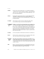
STANDARD WARRANTY
Definitions: This two-year limited warranty applies to the following DataDirect Networks network infrastructure and
individual SAN solution components that include: Silicon Storage Appliance Hardware, Drive Modules, RAID Hardware
Components, Storage Hardware Components, and Disk Drive Docking Bays and Enclosures (hereinafter “DataDirect
Networks Products”). Fibre Channel Interface Kits, SCSI Interface Kits, Host Adapters and Networking Products are
limited to a 90-day warranty. Software bundled or included with DataDirect Networks solutions are furnished
exclusively under the terms of the applicable license agreements.
Warranty: DataDirect Networks warrants that the DataDirect Networks Products accompanied by this limited
Warranty are free from defects in material and workmanship for a period of two years from the date of original purchase
from DataDirect Networks or an authorized DataDirect Networks reseller. During the term of this Warranty, DataDirect
Networks will, at its option, repair or replace any defective parts of the DataDirect Networks products purchased under
this Warranty at no additional charge. Repair parts or replacement DataDirect Networks products will be furnished on
an exchange basis, and will be either reconditioned or new. When returning the DataDirect Networks products, the
Purchaser must prepay any shipping charges. In addition, the Purchaser is responsible for insuring the products
returned and assumes the risk of loss during shipment.
Warranty Claim Requirements: Purchaser claims made pursuant to this Warranty must conform to the following
requirements:
1. The DataDirect Networks products must be returned to (a) an Authorized DataDirect Networks Servicing Reseller
in the country of original purchase, or (b) a DataDirect Networks facility which performs Warranty service in the
country of original purchase, or (c) an Authorized DataDirect Networks Third Party Service Provider in the country
of original purchase.
2. The Purchaser must provide proof of purchase and date of purchase from DataDirect Networks or an Authorized
DataDirect Networks Reseller.
3. The Purchaser may request information on how to obtain warranty service by contacting any Authorized DataDirect
Networks Reseller, or by writing to the Warranty Service Department, DataDirect Networks, 9201 Oakdale Avenue,
Chatsworth, CA 91311.
Disclaimers: THIS LIMITED WARRANTY DOES NOT APPLY TO ANY DATADIRECT NETWORKS PRODUCTS WHICH
HAVE BEEN DAMAGED OR RENDERED DEFECTIVE (a) AS A RESULT OF ACCIDENT, MISUSE, OR ABUSE; (b) BY
THE USE OF PARTS NOT MANUFACTURED OR SOLD BY DATADIRECT NETWORKS; (c) BY MODIFICATION
WITHOUT THE WRITTEN PERMISSION OF DATADIRECT NETWORKS, OR (d) AS A RESULT OF SERVICE BY
ANYONE OTHER THAN DATADIRECT NETWORKS, AN AUTHORIZED DATADIRECT NETWORKS SERVICING
RESELLER, OR AN AUTHORIZED DATADIRECT NETWORKS THIRD PARTY SERVICE PROVIDER.
EXCEPT AS EXPRESSLY SET FORTH ABOVE, DATADIRECT NETWORKS MAKES NO OTHER WARRANTIES,
EXPRESS OR IMPLIED, INCLUDING, BUT NOT LIMITED TO, ANY IMPLIED WARRANTIES OF MERCHANTABILITY
AND FITNESS FOR PURPOSE, AND DATADIRECT NETWORKS EXPRESSLY DISCLAIMS ALL WARRANTIES NOT
STATED HEREIN. IN THE EVENT THE PRODUCTS ARE NOT FREE FROM DEFECTS AS WARRANTED ABOVE,
THE PURCHASER'S SOLE REMEDY SHALL BE REPAIR OR REPLACEMENT AS PROVIDED ABOVE. UNDER NO
CIRCUMSTANCES WILL DATADIRECT NETWORKS BE LIABLE TO THE PURCHASER, OR TO ANY USER, FOR ANY
DAMAGES, EXPENSES, LOST PROFITS, LOST SAVINGS, DAMAGE TO OR REPLACEMENT OF EQUIPMENT AND
PROPERTY, COSTS OF RECOVERING, REPROGRAMMING, OR REPRODUCING ANY PROGRAM OR DATA STORED
IN OR USED WITH THE PRODUCTS, OR OTHER DAMAGES ARISING OUT OF THE USE OR INABILITY TO USE THE
DATADIRECT NETWORKS PRODUCTS.
ANY IMPLIED WARRANTIES ARE LIMITED TO THE TERMS OF THIS EXPRESS LIMITED WARRANTY. SOME
STATES DO NOT ALLOW THE EXCLUSION OR LIMITATION OF INCIDENTAL OR CONSEQUENTIAL DAMAGES
FOR CONSUMER PRODUCTS, AND SOME STATES DO NOT ALLOW LIMITATIONS ON HOW LONG AN IMPLIED
WARRANTY LASTS, SO THE ABOVE LIMITATIONS OR EXCLUSIONS MAY NOT APPLY TO YOU. THIS WARRANTY
GIVES YOU SPECIFIC LEGAL RIGHTS, AND YOU MAY ALSO HAVE OTHER RIGHTS WHICH VARY FROM STATE TO
STATE.
DataDirect Networks EF2800 FC RAID Storage System User Guide (V 1.0)
iii
This page intentionally left blank.
iv
Preface
Preface
What is in this Guide
This user guide gives you step-by-step instructions on how to install,
configure and connect the EF2800 storage subsystem to your host
computer system, and how to use and maintain the system.
Who should use this Guide
This user guide assumes that you have a working knowledge of the
Fibre Channel environment into which you are installing the EF2800
system. If you do not have these skills, or are not confident with the
instructions in this guide, do not proceed with the installation.
International Standards
The EF2800 storage system complies with the requirements of the
following agencies and standards:
• CE to IEC 950/EN60950
• UL 60950
• cUL
Potential for Radio Frequency Interference
USA Federal Communications Commission (FCC)
NOTE : This equipment has been tested and found to comply with the limits
for a class A digital device, pursuant to Part 15 of the FCC rules. These limits
are designed to provide reasonable protection against harmful interference
when the equipment is operated in a commercial environment. This
equipment generates, uses and can radiate radio frequency energy and, if not
installed and used in accordance with the instruction manual, may cause
harmful interference to radio communications. Operation of this equipment
in a residential area is likely to cause harmful interference in which case the
user will be required to correct the interference at his own expense.
Properly shielded and grounded cables and connectors must be used in
order to meet FCC emission limits. The supplier is not responsible for
any radio or television interference caused by using other than
DataDirect Networks EF2800 FC RAID Storage System User Guide (V 1.0)
v
Preface
recommended cables and connectors or by unauthorized changes or
modifications to this equipment. Unauthorized changes or
modifications could void the user’s authority to operate the equipment.
This device complies with Part 15 of the FCC Rules. Operation is
subject to the following two conditions: (1) this device may not cause
harmful interference, and (2) this device must accept any interference
received, including interference that may cause undesired operation.
NOTE : FCC approval only applies when using the supplied screened
Ethernet cable.
European Regulations
This equipment complies with European Regulations EN 55022 Class A:
Limits and Methods of Measurement of Radio Disturbance
Characteristics of Information Technology Equipments and EN50082-1:
Generic Immunity.
Safety
All plug-in modules are part of the fire enclosure and must only be
removed when a replacement can be immediately added. The system
must not be run without all units in place.
Permanently unplug the unit if you think that it has become damaged
in any way and before you move it.
Drive Carrier Module Caution Label:
• Do not operate with modules missing
• Spin down time 30 seconds
vi
DataDirect Networks EF2800 FC RAID Storage System User Guide (V 1.0)
Preface
Chassis Warning Label: Weight Hazard
• An EF2800 enclosure can weigh up to 37kg (81lb). Do not try to lift
it by yourself.
• Do not attempt to lift the enclosure by means of the extended LRC
module or by the handles on the PSU/Cooling module as they are
not designed to support the weight of the populated enclosure.
Controller Module Caution Label: Do not operate with modules
missing
• In order to comply with applicable safety, emission and thermal
requirements no covers should be removed and all bays must be
fitted with plug-in modules.
PSU/Cooling Module Caution Label: Do not operate with modules
missing
DataDirect Networks EF2800 FC RAID Storage System User Guide (V 1.0)
vii
Preface
• The EF2800 unit must only be operated from a power supply input
voltage range of 100 - 120 VAC or 200-240 VAC.
• The plug on the power supply cord is used as the main disconnect
device. Ensure that the socket outlets are located near the
equipment and are easily accessible.
• The equipment is intended to operate with two working PSUs.
• If powered by multiple AC sources, disconnect all supply power for
complete isolation.
PSU Warning Label: Power Hazards
• The power connection should always be disconnected prior to
removal of the Power Supply/Cooling module from the enclosure.
• A safe electrical earth connection must be provided to the power
cord. Check the grounding of the enclosure before applying power.
• Provide a suitable power source with electrical overload
protection to meet the requirements laid down in the technical
specification.
• A faulty Power Supply/Cooling module must be replaced with a
fully operational module within 24 hours.
Warning ! Do not remove covers from the PSU. Danger of electric shock
inside. Return the PSU to your supplier for repair.
PSU Safety Label: Electric Shock Hazard Inside
Caution ! If this equipment is used in a manner not specified by the
manufacturer, the protection provided by the equipment may be
impaired.
viii
DataDirect Networks EF2800 FC RAID Storage System User Guide (V 1.0)
Preface
Battery Safety
The battery is user replaceable, please refer to the Battery Replacement
Procedure.
Warning ! There is a danger of explosion if the battery is incorrectly
replaced.
• Dispose of used batteries in accordance with the manufacturer’s
instructions and National regulations.
Laser Safety
Class 1 Laser Product
When the EF2800 is supplied with optical modules they contain a laser
that complies with Laser Class 1, US 21 CFR (J) and EN 60825-1.
If optical modules are to be provided and fitted by the end user, lasers
must comply with the standards listed above.
Rack System Precautions
The following safety requirements must be considered when the unit is
mounted in a rack.
• The rack design should incorporate stabilizing features suitable to
prevent the rack from tipping or being pushed over during
installation or in normal use.
• When loading a rack with the units, fill the rack from the bottom up
and empty from the top down.
• The rack should comply with the airflow requirements detailed in
the technical specification.
• The rack design should take into consideration the maximum
operating ambient temperature for the unit, which is 40°C when
dual cooling modules are fitted.
• The rack should have a safe electrical distribution system. It must
provide overcurrent protection for the unit and must not be
overloaded by the total number of units installed in the rack.
DataDirect Networks EF2800 FC RAID Storage System User Guide (V 1.0)
ix
Preface
Consideration of the units nameplate rating should be used when
addressing these concerns.
• The electrical distribution system must provide a reliable earth for
each unit and the rack.
• Each power supply in each unit has an earth leakage current of
0.65mA. The design of the electrical distribution system must take
into consideration the total earth leakage current from all the
power supplies in all the units. The rack will require labelling with
“HIGH LEAKAGE CURRENT. Earth connection essential before
connecting supply”.
• The rack when configured with the units must meet the safety
requirements of UL 1950 and IEC 60950.
ESD Precautions
Caution ! It is recommended that you fit and check a suitable anti-static
wrist or ankle strap and observe all conventional ESD precautions when
handling EF2800 plug-in modules and components. Avoid contact with
backplane components and module connectors, etc.
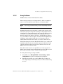
Electrical Surges
A powerful electrical surge (2,000 volts), primarily associated with a
lightning strike, may cause a Storage Manager (SM) to go offline or
restart. You may have to manually put the SM module back online.
Review the event log to determine the SM’s status (see section 7.2 on
page 108) and take the appropriate action based on its status. For
information about restarting an SM, see section 4.3.1 on page 62. For
information about putting an SM online, see section 4.3.4 on page 64.
Tests show that electrical surges up to 2,000 volts coming through the
AC connection will not damage the SM hardware.
x
DataDirect Networks EF2800 FC RAID Storage System User Guide (V 1.0)
Preface
Data Security
• Power down your host computer and all attached peripheral
devices before beginning installation.
• Each enclosure contains up to 16 removable disk drive modules.
Disk units are fragile. Handle them with care, and keep them away
from strong magnetic fields.
• All the supplied plug-in modules and blanking plates must be in
place for the air to flow correctly around the enclosure and also to
complete the internal circuitry.
• If the enclosure is used with modules or blanking plates missing for
more than a few minutes, the enclosure can overheat, causing
power failure and data loss. Such use may also invalidate the
warranty.
• If you remove any drive module, you may lose data.
- If you remove a drive module, replace it immediately. If it is
faulty, replace it with a drive module of the same type and
capacity
• Ensure that all disk drives are removed from the enclosure before
attempting to manhandle or move the rack installation.
• Do not abandon your backup routines. No system is completely
foolproof.
Special Tools and Equipment
There are no special tools required but in order to complete the
assembly of some configurations you may need the following:
• Security keys (one of these should be included with your EF2800
enclosure for use with the drive locks).
DataDirect Networks EF2800 FC RAID Storage System User Guide (V 1.0)
xi
This page intentionally left blank.
xii
Table of Contents
Table of Contents
Preface . . . . . . . . . . . . . . . . . . . . . . . . . . . . . . . . . . . . . . . . . . . . . . . . . . . . . . . . . . . . . . . . v
1
Introduction . . . . . . . . . . . . . . . . . . . . . . . . . . . . . . . . . . . . . . . . . . . . . . . . 1
1.1
1.1.1
1.2
1.2.1
1.2.2
1.2.3
1.2.4
1.2.5
1.3
1.4
The Enclosure Core Product . . . . . . . . . . . . . . . . . . . . . . . . . . . . . . . . . 3
Enclosure Chassis . . . . . . . . . . . . . . . . . . . . . . . . . . . . . . . . . . . . . . . . . . . . . 4
The Plug-in Modules. . . . . . . . . . . . . . . . . . . . . . . . . . . . . . . . . . . . . . . . . 5
Power Supply/Cooling Module . . . . . . . . . . . . . . . . . . . . . . . . . . . . . . . . . 5
Operators Panel . . . . . . . . . . . . . . . . . . . . . . . . . . . . . . . . . . . . . . . . . . . . . . . 6
LRCI/O Module (FC-AL). . . . . . . . . . . . . . . . . . . . . . . . . . . . . . . . . . . . . . . . 7
Drive Carrier Module . . . . . . . . . . . . . . . . . . . . . . . . . . . . . . . . . . . . . . . . . 10
Dummy Carrier Modules . . . . . . . . . . . . . . . . . . . . . . . . . . . . . . . . . . . . . . 11
Visible and Audible Alarms . . . . . . . . . . . . . . . . . . . . . . . . . . . . . . . . . . 12
Internal Drive Loop Structure. . . . . . . . . . . . . . . . . . . . . . . . . . . . . . . . 12
2
Getting Started. . . . . . . . . . . . . . . . . . . . . . . . . . . . . . . . . . . . . . . . . . . 15
2.1
2.1.1
2.2
2.2.1
2.2.2
2.2.3
2.3
2.3.1
2.3.2
2.4
2.4.1
2.4.2
2.5
2.6
2.7
2.7.1
2.7.2
2.7.3
2.7.4
Planning Your Installation. . . . . . . . . . . . . . . . . . . . . . . . . . . . . . . . . . . 16
Enclosure Bay Numbering Convention . . . . . . . . . . . . . . . . . . . . . . . . 16
Rack-Mounting the Enclosure . . . . . . . . . . . . . . . . . . . . . . . . . . . . . . . 17
Pre-Requisites . . . . . . . . . . . . . . . . . . . . . . . . . . . . . . . . . . . . . . . . . . . . . . . . 17
Unpacking the EF2800 . . . . . . . . . . . . . . . . . . . . . . . . . . . . . . . . . . . . . . . . 18
Installing the Enclosure in Rack . . . . . . . . . . . . . . . . . . . . . . . . . . . . . . . 19
Power Supply/Cooling Module Installation . . . . . . . . . . . . . . . . . . . . 22
Parts Check List . . . . . . . . . . . . . . . . . . . . . . . . . . . . . . . . . . . . . . . . . . . . . . 22
Procedure . . . . . . . . . . . . . . . . . . . . . . . . . . . . . . . . . . . . . . . . . . . . . . . . . . . . 22
Controller I/O Module Installation . . . . . . . . . . . . . . . . . . . . . . . . . . . . 24
Parts Check List . . . . . . . . . . . . . . . . . . . . . . . . . . . . . . . . . . . . . . . . . . . . . . 24
Procedure . . . . . . . . . . . . . . . . . . . . . . . . . . . . . . . . . . . . . . . . . . . . . . . . . . . . 24
Drive Module Installation . . . . . . . . . . . . . . . . . . . . . . . . . . . . . . . . . . . 26
Verify Configuration Switch Settings on Ops Panel. . . . . . . . . . . . . . 28
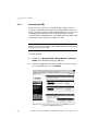
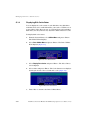
Connecting the Enclosure to FC Host and Disk Ports . . . . . . . . . . . 29
Expansion Enclosures . . . . . . . . . . . . . . . . . . . . . . . . . . . . . . . . . . . . . . . . 31
Enclosure Device Addressing . . . . . . . . . . . . . . . . . . . . . . . . . . . . . . . . . 31
Connecting to the RS-232 Port (Optional) . . . . . . . . . . . . . . . . . . . . . . 34
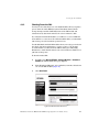
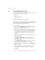
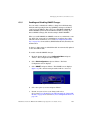
Connecting to the Ethernet Port . . . . . . . . . . . . . . . . . . . . . . . . . . . . . . . 35
DataDirect Networks EF2800 FC RAID Storage System User Guide (V 1.0)
xiii
Table of Contents
xiv
2.8
2.8.1
2.8.2
2.9
2.9.1
2.9.2
2.9.3
2.10
Powering On the Enclosures. . . . . . . . . . . . . . . . . . . . . . . . . . . . . . . . . 36
Grounding Checks . . . . . . . . . . . . . . . . . . . . . . . . . . . . . . . . . . . . . . . . . . . .36
Powering On . . . . . . . . . . . . . . . . . . . . . . . . . . . . . . . . . . . . . . . . . . . . . . . . . .37
Status LED Indicators . . . . . . . . . . . . . . . . . . . . . . . . . . . . . . . . . . . . . . 38
Power Supply/Cooling Module LEDs . . . . . . . . . . . . . . . . . . . . . . . . . . .38
Ops Panel LEDs . . . . . . . . . . . . . . . . . . . . . . . . . . . . . . . . . . . . . . . . . . . . . . .38
Disk Drives LEDs . . . . . . . . . . . . . . . . . . . . . . . . . . . . . . . . . . . . . . . . . . . . .40
Understanding how the SMs Work Together . . . . . . . . . . . . . . . . . . . 41
3
Accessing the EF2800 SAM Software . . . . . . . . . . . . .43
3.1
3.1.1
3.2
3.2.1
3.3
3.3.1
3.3.2
3.3.3
3.4
3.4.1
3.5
3.5.1
3.5.2
SAM System Requirements . . . . . . . . . . . . . . . . . . . . . . . . . . . . . . . . . . 44
Configuring Your System to Work with SAM . . . . . . . . . . . . . . . . . . . .44
Configuring the EF2800 for TCP/IP . . . . . . . . . . . . . . . . . . . . . . . . . . . 45
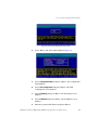
Accessing EF2800 via Serial Port & Disk Array Administrator . . .46
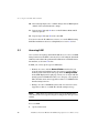
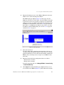
Accessing SAM . . . . . . . . . . . . . . . . . . . . . . . . . . . . . . . . . . . . . . . . . . . . 48
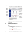
Understanding the Page Refresh Icons . . . . . . . . . . . . . . . . . . . . . . . . .50
Navigating in EF2800 SAM . . . . . . . . . . . . . . . . . . . . . . . . . . . . . . . . . . . . .51
Logging Off SAM . . . . . . . . . . . . . . . . . . . . . . . . . . . . . . . . . . . . . . . . . . . . . .51
Configuring the IP Settings Using SAM . . . . . . . . . . . . . . . . . . . . . . . . 52
Configuring the HTTP Setting . . . . . . . . . . . . . . . . . . . . . . . . . . . . . . . . . .53
Setting SAM Passwords and Preferences . . . . . . . . . . . . . . . . . . . . . . 53
Setting SAM Passwords. . . . . . . . . . . . . . . . . . . . . . . . . . . . . . . . . . . . . . . .53
Setting Your User Preferences . . . . . . . . . . . . . . . . . . . . . . . . . . . . . . . . .54
4
Setting Up the EF2800 . . . . . . . . . . . . . . . . . . . . . . . . . . . . . . . . .57
4.1
4.1.1
4.1.2
4.1.3
4.2
4.2.1
4.2.2
4.3
4.3.1
4.3.2
4.3.3
4.3.4
4.3.5
4.3.6
Setting Up the Host Ports . . . . . . . . . . . . . . . . . . . . . . . . . . . . . . . . . . . 57
FC Host Port Link Speed . . . . . . . . . . . . . . . . . . . . . . . . . . . . . . . . . . . . . .57
FC Host Port Loop IDs . . . . . . . . . . . . . . . . . . . . . . . . . . . . . . . . . . . . . . . .58
FC Host Port Topology . . . . . . . . . . . . . . . . . . . . . . . . . . . . . . . . . . . . . . . .59
Setting Up the FC Device Ports . . . . . . . . . . . . . . . . . . . . . . . . . . . . . . 60
FC Device Port Loop IDs . . . . . . . . . . . . . . . . . . . . . . . . . . . . . . . . . . . . . .60
FC Device Port Link Speed . . . . . . . . . . . . . . . . . . . . . . . . . . . . . . . . . . . .60
Restarting the SMs . . . . . . . . . . . . . . . . . . . . . . . . . . . . . . . . . . . . . . . . . 61
Restarting the SMs . . . . . . . . . . . . . . . . . . . . . . . . . . . . . . . . . . . . . . . . . . . .62
Shutting Down the SMs . . . . . . . . . . . . . . . . . . . . . . . . . . . . . . . . . . . . . . . .63
Putting an SM Offline . . . . . . . . . . . . . . . . . . . . . . . . . . . . . . . . . . . . . . . . . .64
Putting an SM Online . . . . . . . . . . . . . . . . . . . . . . . . . . . . . . . . . . . . . . . . . .64
Killing an SM . . . . . . . . . . . . . . . . . . . . . . . . . . . . . . . . . . . . . . . . . . . . . . . . . .65
Restarting the LAN Subsystem . . . . . . . . . . . . . . . . . . . . . . . . . . . . . . . .66
DataDirect Networks EF2800 FC RAID Storage System User Guide (V 1.0)
Table of Contents
5
Creating and Managing Arrays & Partitions . . . 67
5.1
5.2
5.2.1
5.2.2
5.2.3
5.2.4
5.3
5.3.1
5.3.2
5.3.3
5.4
5.4.1
5.4.2
5.4.3
Creating Arrays . . . . . . . . . . . . . . . . . . . . . . . . . . . . . . . . . . . . . . . . . . . . 67
Managing Arrays . . . . . . . . . . . . . . . . . . . . . . . . . . . . . . . . . . . . . . . . . . . 74
Understanding the Array Icons . . . . . . . . . . . . . . . . . . . . . . . . . . . . . . . . 74
Stopping the Array Initialization Process. . . . . . . . . . . . . . . . . . . . . . . 75
Reconstructing an Array . . . . . . . . . . . . . . . . . . . . . . . . . . . . . . . . . . . . . . 75
Expanding Array Capacity . . . . . . . . . . . . . . . . . . . . . . . . . . . . . . . . . . . . 76
Managing Partitions . . . . . . . . . . . . . . . . . . . . . . . . . . . . . . . . . . . . . . . . 78
Understanding Partitions . . . . . . . . . . . . . . . . . . . . . . . . . . . . . . . . . . . . . . 78
Adding a Partition . . . . . . . . . . . . . . . . . . . . . . . . . . . . . . . . . . . . . . . . . . . . 80
Expanding a Partition . . . . . . . . . . . . . . . . . . . . . . . . . . . . . . . . . . . . . . . . . 81
Managing Spares. . . . . . . . . . . . . . . . . . . . . . . . . . . . . . . . . . . . . . . . . . . 82
Enabling Dynamic Spares . . . . . . . . . . . . . . . . . . . . . . . . . . . . . . . . . . . . . 83
Managing Dedicated Spares . . . . . . . . . . . . . . . . . . . . . . . . . . . . . . . . . . . 84
Managing Global Spares. . . . . . . . . . . . . . . . . . . . . . . . . . . . . . . . . . . . . . . 85
6
RAID Management . . . . . . . . . . . . . . . . . . . . . . . . . . . . . . . . . . . . . 87
6.1
6.2
6.2.1
6.2.2
6.2.3
6.2.4
6.2.5
6.2.6
6.2.7
6.3
6.3.1
6.3.2
6.3.3
6.3.4
6.3.5
6.3.6
Managing Arrays and Partitions Using SAM . . . . . . . . . . . . . . . . . . . . 87
Managing Arrays . . . . . . . . . . . . . . . . . . . . . . . . . . . . . . . . . . . . . . . . . . . 88
Viewing Array and Drive Status Information . . . . . . . . . . . . . . . . . . . 88
Viewing Array and Partition Statistics . . . . . . . . . . . . . . . . . . . . . . . . . 89
Verifying an Array . . . . . . . . . . . . . . . . . . . . . . . . . . . . . . . . . . . . . . . . . . . . 91
Changing Array Ownership . . . . . . . . . . . . . . . . . . . . . . . . . . . . . . . . . . . . 92
Changing an Array Name . . . . . . . . . . . . . . . . . . . . . . . . . . . . . . . . . . . . . . 93
Trusting an Array . . . . . . . . . . . . . . . . . . . . . . . . . . . . . . . . . . . . . . . . . . . . . 93
Deleting an Array . . . . . . . . . . . . . . . . . . . . . . . . . . . . . . . . . . . . . . . . . . . . . 95
Managing Partitions . . . . . . . . . . . . . . . . . . . . . . . . . . . . . . . . . . . . . . . . 96
Viewing Partition Status Information . . . . . . . . . . . . . . . . . . . . . . . . . . 96
Changing a Partition Name . . . . . . . . . . . . . . . . . . . . . . . . . . . . . . . . . . . . 96
Changing a Partition LUN . . . . . . . . . . . . . . . . . . . . . . . . . . . . . . . . . . . . . 97
Controlling Partition Access. . . . . . . . . . . . . . . . . . . . . . . . . . . . . . . . . . . 98
Changing the Read-Ahead Cache Size . . . . . . . . . . . . . . . . . . . . . . . . . 103
Deleting a Partition . . . . . . . . . . . . . . . . . . . . . . . . . . . . . . . . . . . . . . . . . . 104
7
Monitoring System Status . . . . . . . . . . . . . . . . . . . . . . . . . . 105
7.1
7.2
7.3
Displaying SAM Status Information . . . . . . . . . . . . . . . . . . . . . . . . . . 105
Displaying the Event Log. . . . . . . . . . . . . . . . . . . . . . . . . . . . . . . . . . . 108
Setting Up Remote Notification . . . . . . . . . . . . . . . . . . . . . . . . . . . . . 110
DataDirect Networks EF2800 FC RAID Storage System User Guide (V 1.0)
xv
Table of Contents
xvi
7.3.1
7.3.2
7.3.3
7.4
7.5
7.5.1
Starting and Stopping Remote Notification . . . . . . . . . . . . . . . . . . . .110
Setting Up the Events to be Monitored . . . . . . . . . . . . . . . . . . . . . . . .110
Setting Up the Email Addresses . . . . . . . . . . . . . . . . . . . . . . . . . . . . . . .111
Saving Log Information to a File . . . . . . . . . . . . . . . . . . . . . . . . . . . . 112
Displaying Overall Statistics . . . . . . . . . . . . . . . . . . . . . . . . . . . . . . . . 113
Resetting the All Statistics . . . . . . . . . . . . . . . . . . . . . . . . . . . . . . . . . . . .114
8
Other EF2800 Configurations . . . . . . . . . . . . . . . . . . . . . .115
8.1
8.1.1
8.1.2
8.1.3
8.1.4
8.1.5
8.2
8.3
8.3.1
8.4
8.5
8.6
8.7
8.8
8.9
8.10
8.11
8.11.1
8.11.2
8.12
8.12.1
8.12.2
8.13
Configuring the LAN-related Settings . . . . . . . . . . . . . . . . . . . . . . . . 116
Configuring the Telnet Timeout . . . . . . . . . . . . . . . . . . . . . . . . . . . . . . .116
Configuring the SNMP Settings . . . . . . . . . . . . . . . . . . . . . . . . . . . . . . .116
Configuring the System Information . . . . . . . . . . . . . . . . . . . . . . . . . .117
Setting Passwords . . . . . . . . . . . . . . . . . . . . . . . . . . . . . . . . . . . . . . . . . . . .118
Configuring the Security Options . . . . . . . . . . . . . . . . . . . . . . . . . . . . .119
Changing the Date and Time. . . . . . . . . . . . . . . . . . . . . . . . . . . . . . . . 120
Understanding LUNs and Viewing LUN Information. . . . . . . . . . . . 120
Viewing LUN Information. . . . . . . . . . . . . . . . . . . . . . . . . . . . . . . . . . . . .121
Changing Management LUNs . . . . . . . . . . . . . . . . . . . . . . . . . . . . . . . 121
Changing the Alarm Mute Setting. . . . . . . . . . . . . . . . . . . . . . . . . . . . 122
Controlling Host Access to EF2800’s Write-back Cache Setting . . 124
Enabling and Disabling the Battery . . . . . . . . . . . . . . . . . . . . . . . . . . 124
Changing the Utility Priority . . . . . . . . . . . . . . . . . . . . . . . . . . . . . . . . 125
Rescanning All Ports . . . . . . . . . . . . . . . . . . . . . . . . . . . . . . . . . . . . . . 126
Pausing I/O . . . . . . . . . . . . . . . . . . . . . . . . . . . . . . . . . . . . . . . . . . . . . . 126
Saving and Restoring a Configuration File . . . . . . . . . . . . . . . . . . . . 127
Saving a Configuration File . . . . . . . . . . . . . . . . . . . . . . . . . . . . . . . . . . .127
Restoring a Configuration File . . . . . . . . . . . . . . . . . . . . . . . . . . . . . . . .128
Viewing and Restoring Default Settings . . . . . . . . . . . . . . . . . . . . . . 130
Viewing Default Settings . . . . . . . . . . . . . . . . . . . . . . . . . . . . . . . . . . . . . .130
Restoring Default Settings . . . . . . . . . . . . . . . . . . . . . . . . . . . . . . . . . . . .130
Updating Software . . . . . . . . . . . . . . . . . . . . . . . . . . . . . . . . . . . . . . . . 131
9
Managing Disk Drives & Enclosures . . . . . . . . . . . . . .133
9.1
9.1.1
9.1.2
9.1.3
9.1.4
Managing Disk Drives . . . . . . . . . . . . . . . . . . . . . . . . . . . . . . . . . . . . . 134
Displaying Disk Drive Information . . . . . . . . . . . . . . . . . . . . . . . . . . . .134
Clearing Metadata from a Disk Drive . . . . . . . . . . . . . . . . . . . . . . . . . .135
Enabling and Disabling Write-back Cache . . . . . . . . . . . . . . . . . . . . .135
Displaying Disk Drive Cache Status . . . . . . . . . . . . . . . . . . . . . . . . . . .136
DataDirect Networks EF2800 FC RAID Storage System User Guide (V 1.0)
Table of Contents
9.1.5
9.1.6
9.1.7
9.1.8
9.2
9.2.1
9.2.2
Enabling and Disabling SMART Changes. . . . . . . . . . . . . . . . . . . . . . 136
Blinking a Drive LED . . . . . . . . . . . . . . . . . . . . . . . . . . . . . . . . . . . . . . . . 137
Taking Down a Disk Drive . . . . . . . . . . . . . . . . . . . . . . . . . . . . . . . . . . . 137
Testing a Disk Drive . . . . . . . . . . . . . . . . . . . . . . . . . . . . . . . . . . . . . . . . . 138
Managing Enclosures . . . . . . . . . . . . . . . . . . . . . . . . . . . . . . . . . . . . . . 139
Setting the EMP LUN . . . . . . . . . . . . . . . . . . . . . . . . . . . . . . . . . . . . . . . . 139
Changing the Additional EMP Setting . . . . . . . . . . . . . . . . . . . . . . . . 140
10
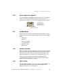
Troubleshooting and Problem Solving. . . . . . . . . 141
10.1
10.1.1
10.2
10.2.1
10.2.2
10.2.3
10.3
10.3.1
10.3.2
10.4
10.4.1
10.4.2
10.4.3
10.4.4
10.5
10.5.1
10.5.2
10.6
10.6.1
10.7
10.7.1
10.7.2
10.7.3
10.7.4
10.8
10.9
10.10
10.11
10.12
10.13
Overview . . . . . . . . . . . . . . . . . . . . . . . . . . . . . . . . . . . . . . . . . . . . . . . . 141
Initial Start-up Problems . . . . . . . . . . . . . . . . . . . . . . . . . . . . . . . . . . . . . 141
LEDs. . . . . . . . . . . . . . . . . . . . . . . . . . . . . . . . . . . . . . . . . . . . . . . . . . . . 143
Ops Panel . . . . . . . . . . . . . . . . . . . . . . . . . . . . . . . . . . . . . . . . . . . . . . . . . . . 143
Controller I/O Module . . . . . . . . . . . . . . . . . . . . . . . . . . . . . . . . . . . . . . . . 145
Power Supply/Cooling Module . . . . . . . . . . . . . . . . . . . . . . . . . . . . . . . 147
Audible Alarm . . . . . . . . . . . . . . . . . . . . . . . . . . . . . . . . . . . . . . . . . . . . 147
Audible Alarm Mute. . . . . . . . . . . . . . . . . . . . . . . . . . . . . . . . . . . . . . . . . . 147
LED Test Mode . . . . . . . . . . . . . . . . . . . . . . . . . . . . . . . . . . . . . . . . . . . . . . 147
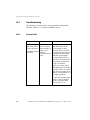
Troubleshooting . . . . . . . . . . . . . . . . . . . . . . . . . . . . . . . . . . . . . . . . . . 148
System Faults . . . . . . . . . . . . . . . . . . . . . . . . . . . . . . . . . . . . . . . . . . . . . . . 148
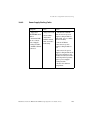
Power Supply/Cooling Faults . . . . . . . . . . . . . . . . . . . . . . . . . . . . . . . . . 149
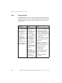
Thermal Control . . . . . . . . . . . . . . . . . . . . . . . . . . . . . . . . . . . . . . . . . . . . . 150
Thermal Alarm . . . . . . . . . . . . . . . . . . . . . . . . . . . . . . . . . . . . . . . . . . . . . . 151
Drive Carrier Module Faults . . . . . . . . . . . . . . . . . . . . . . . . . . . . . . . . 152
Dummy Carrier Modules . . . . . . . . . . . . . . . . . . . . . . . . . . . . . . . . . . . . . 152
Auto Start Failure . . . . . . . . . . . . . . . . . . . . . . . . . . . . . . . . . . . . . . . . . . . . 152
Dealing with Hardware Faults . . . . . . . . . . . . . . . . . . . . . . . . . . . . . . 153
Continuous Operation During Replacement . . . . . . . . . . . . . . . . . . . 153
Replacing a Module . . . . . . . . . . . . . . . . . . . . . . . . . . . . . . . . . . . . . . . 153
Power Supply/Cooling Modules . . . . . . . . . . . . . . . . . . . . . . . . . . . . . . 154
Ops Panel . . . . . . . . . . . . . . . . . . . . . . . . . . . . . . . . . . . . . . . . . . . . . . . . . . . 155
Storage Manager Module . . . . . . . . . . . . . . . . . . . . . . . . . . . . . . . . . . . . . 156
Drive Carrier Module . . . . . . . . . . . . . . . . . . . . . . . . . . . . . . . . . . . . . . . . 158
Problems Accessing the EF2800 via Ethernet Port . . . . . . . . . . . . . 159
Host Fibre Channel Problems. . . . . . . . . . . . . . . . . . . . . . . . . . . . . . . 160
Array Problems . . . . . . . . . . . . . . . . . . . . . . . . . . . . . . . . . . . . . . . . . . . 161
EF2800 Problems . . . . . . . . . . . . . . . . . . . . . . . . . . . . . . . . . . . . . . . . . 162
Problems During Startup (when using Disk Array Administrator) 162
Terminal Emulator and COM Port Problems . . . . . . . . . . . . . . . . . . 163
DataDirect Networks EF2800 FC RAID Storage System User Guide (V 1.0)
xvii
Table of Contents
10.14
10.14.1
10.14.2
10.15
10.15.1
10.15.2
10.16
10.17
10.18
10.18.1
10.18.2
10.18.3
10.19
Warning and Error Events. . . . . . . . . . . . . . . . . . . . . . . . . . . . . . . . . . 165
Warnings. . . . . . . . . . . . . . . . . . . . . . . . . . . . . . . . . . . . . . . . . . . . . . . . . . . . .165
Errors . . . . . . . . . . . . . . . . . . . . . . . . . . . . . . . . . . . . . . . . . . . . . . . . . . . . . . .169
Setting Up and Viewing the Debug Log . . . . . . . . . . . . . . . . . . . . . . . 170
Collecting Debug Logs . . . . . . . . . . . . . . . . . . . . . . . . . . . . . . . . . . . . . . . .170
Configuring Debug Logs . . . . . . . . . . . . . . . . . . . . . . . . . . . . . . . . . . . . . .172
Using the Loader Diagnostics Menu . . . . . . . . . . . . . . . . . . . . . . . . . 173
Using the Loader Utility Menu . . . . . . . . . . . . . . . . . . . . . . . . . . . . . . 173
Understanding Disk-related Errors . . . . . . . . . . . . . . . . . . . . . . . . . . 173
Disk Errors . . . . . . . . . . . . . . . . . . . . . . . . . . . . . . . . . . . . . . . . . . . . . . . . . .174
Disk Channel Errors . . . . . . . . . . . . . . . . . . . . . . . . . . . . . . . . . . . . . . . . . .175
Voltage and Temperature Errors and Warnings . . . . . . . . . . . . . . . .177
Slow Write Performance . . . . . . . . . . . . . . . . . . . . . . . . . . . . . . . . . . . 177
Appendix A. Enclosure Specifications . . . . . . . . . . . . . . . . . . .
A.1
A.1.1
A.1.2
A.1.3
A.1.4
A.1.5
A.1.6
A.1.7
A.1.8
A.1.9
A.1.10
A.1.11
A.2
Technical Specifications . . . . . . . . . . . . . . . . . . . . . . . . . . . . . . . . . . . 179
Dimensions . . . . . . . . . . . . . . . . . . . . . . . . . . . . . . . . . . . . . . . . . . . . . . . . . .179
Weight . . . . . . . . . . . . . . . . . . . . . . . . . . . . . . . . . . . . . . . . . . . . . . . . . . . . . . .179
AC Power (450W PSU) . . . . . . . . . . . . . . . . . . . . . . . . . . . . . . . . . . . . . . .179
PSU Safety and EMC Compliance . . . . . . . . . . . . . . . . . . . . . . . . . . . . .180
Power Cords . . . . . . . . . . . . . . . . . . . . . . . . . . . . . . . . . . . . . . . . . . . . . . . . .180
Environment . . . . . . . . . . . . . . . . . . . . . . . . . . . . . . . . . . . . . . . . . . . . . . . . .180
Interfaces . . . . . . . . . . . . . . . . . . . . . . . . . . . . . . . . . . . . . . . . . . . . . . . . . . . .181
Controller I/O Module Specification . . . . . . . . . . . . . . . . . . . . . . . . . . .182
Drive Carrier Module Specification . . . . . . . . . . . . . . . . . . . . . . . . . . .183
RAID Card . . . . . . . . . . . . . . . . . . . . . . . . . . . . . . . . . . . . . . . . . . . . . . . . . . .183
Software Enclosure Services (SES) Support . . . . . . . . . . . . . . . . . . .183
Spare Parts and Accessories . . . . . . . . . . . . . . . . . . . . . . . . . . . . . . . . 184
Appendix B. Array Basics . . . . . . . . . . . . . . . . . . . . . . . . . . . . . . . . . . . . .
B.1
B.1.1
B.1.2
B.1.3
B.1.4
B.1.5
B.1.6
B.1.7
B.2
xviii
179
185
Array Types . . . . . . . . . . . . . . . . . . . . . . . . . . . . . . . . . . . . . . . . . . . . . . 186
RAID 0 (Striped Disks) . . . . . . . . . . . . . . . . . . . . . . . . . . . . . . . . . . . . . . .186
RAID 1, RAID 10 (Mirrored Disks) . . . . . . . . . . . . . . . . . . . . . . . . . . . .187
RAID 3 . . . . . . . . . . . . . . . . . . . . . . . . . . . . . . . . . . . . . . . . . . . . . . . . . . . . . . .187
RAID 4 . . . . . . . . . . . . . . . . . . . . . . . . . . . . . . . . . . . . . . . . . . . . . . . . . . . . . . .188
RAID 5 . . . . . . . . . . . . . . . . . . . . . . . . . . . . . . . . . . . . . . . . . . . . . . . . . . . . . . .188
RAID 50 . . . . . . . . . . . . . . . . . . . . . . . . . . . . . . . . . . . . . . . . . . . . . . . . . . . . . .188
Volume Sets . . . . . . . . . . . . . . . . . . . . . . . . . . . . . . . . . . . . . . . . . . . . . . . . . .189
Comparing RAID Levels . . . . . . . . . . . . . . . . . . . . . . . . . . . . . . . . . . . 189
DataDirect Networks EF2800 FC RAID Storage System User Guide (V 1.0)
Table of Contents
B.3
Mixing Disks from Different Manufacturers/ Capacities. . . . . . . . . 191
Appendix C. Accessing Disk Array
Administrator Software . . . . . . . . . . . . . . . . . . . . . . . . . . . . . . . . . . . . 193
C.1
C.2
C.2.1
C.2.2
C.3
C.3.1
C.3.2
Via the RS-232 Serial Port . . . . . . . . . . . . . . . . . . . . . . . . . . . . . . . . . . 194
Via the Ethernet Port . . . . . . . . . . . . . . . . . . . . . . . . . . . . . . . . . . . . . . 197
Set Up for First Time Use . . . . . . . . . . . . . . . . . . . . . . . . . . . . . . . . . . . . 197
Procedure . . . . . . . . . . . . . . . . . . . . . . . . . . . . . . . . . . . . . . . . . . . . . . . . . . . 197
Navigating the Disk Array Administrator Software . . . . . . . . . . . . . 200
Changing the Screen Display . . . . . . . . . . . . . . . . . . . . . . . . . . . . . . . . . 200
Disk Array Administrator Menu Tree . . . . . . . . . . . . . . . . . . . . . . . . . 201
Appendix D. Creating and Managing
Arrays & Partitions . . . . . . . . . . . . . . . . . . . . . . . . . . . . . . . . . . . . . . . . . . . . 205
D.1
D.1.1
D.1.2
D.2
D.2.1
D.2.2
D.2.3
D.2.4
D.2.5
D.2.6
D.2.7
D.2.8
D.2.9
D.2.10
D.3
D.3.1
D.3.2
D.3.3
D.3.4
D.3.5
D.3.6
D.3.7
D.3.8
D.3.9
Creating Arrays . . . . . . . . . . . . . . . . . . . . . . . . . . . . . . . . . . . . . . . . . . . 205
Creating a Single-Partition Array . . . . . . . . . . . . . . . . . . . . . . . . . . . . . 206
Creating a Multiple-Partition Array . . . . . . . . . . . . . . . . . . . . . . . . . . . 212
Managing Arrays . . . . . . . . . . . . . . . . . . . . . . . . . . . . . . . . . . . . . . . . . . 218
Viewing Array and Drive Status Information . . . . . . . . . . . . . . . . . . 218
Stopping the Array Initialization Process. . . . . . . . . . . . . . . . . . . . . . 222
Adding a Partition . . . . . . . . . . . . . . . . . . . . . . . . . . . . . . . . . . . . . . . . . . . 222
Verifying an Array . . . . . . . . . . . . . . . . . . . . . . . . . . . . . . . . . . . . . . . . . . . 225
Reconstructing an Array . . . . . . . . . . . . . . . . . . . . . . . . . . . . . . . . . . . . . 227
Expanding Array Capacity . . . . . . . . . . . . . . . . . . . . . . . . . . . . . . . . . . . 228
Changing an Array Name . . . . . . . . . . . . . . . . . . . . . . . . . . . . . . . . . . . . . 231
Changing Array Ownership . . . . . . . . . . . . . . . . . . . . . . . . . . . . . . . . . . . 231
Trusting an Array . . . . . . . . . . . . . . . . . . . . . . . . . . . . . . . . . . . . . . . . . . . . 232
Deleting an Array . . . . . . . . . . . . . . . . . . . . . . . . . . . . . . . . . . . . . . . . . . . . 234
Managing Partitions . . . . . . . . . . . . . . . . . . . . . . . . . . . . . . . . . . . . . . . 235
Understanding Partitions . . . . . . . . . . . . . . . . . . . . . . . . . . . . . . . . . . . . . 235
Viewing Partition Status Information . . . . . . . . . . . . . . . . . . . . . . . . . 237
Expanding a Partition . . . . . . . . . . . . . . . . . . . . . . . . . . . . . . . . . . . . . . . . 243
Changing a Partition Name . . . . . . . . . . . . . . . . . . . . . . . . . . . . . . . . . . . 244
Changing a Partition LUN . . . . . . . . . . . . . . . . . . . . . . . . . . . . . . . . . . . . 245
Changing the Read-Ahead Cache Size . . . . . . . . . . . . . . . . . . . . . . . . . 247
Enabling or Disabling Write-back Cache . . . . . . . . . . . . . . . . . . . . . . 249
Controlling Partition Access. . . . . . . . . . . . . . . . . . . . . . . . . . . . . . . . . . 250
Deleting a Partition . . . . . . . . . . . . . . . . . . . . . . . . . . . . . . . . . . . . . . . . . . 257
DataDirect Networks EF2800 FC RAID Storage System User Guide (V 1.0)
xix
Table of Contents
Appendix E. Monitoring System Status . . . . . . . . . . . . . . . . .
259
E.1
Introduction . . . . . . . . . . . . . . . . . . . . . . . . . . . . . . . . . . . . . . . . . . . . . 259
E.2
E.2.1
E.2.2
E.2.3
E.2.4
Displaying the Event Log. . . . . . . . . . . . . . . . . . . . . . . . . . . . . . . . . . . 260
Viewing the Most Recent Event . . . . . . . . . . . . . . . . . . . . . . . . . . . . . . .261
Viewing One Event at a Time . . . . . . . . . . . . . . . . . . . . . . . . . . . . . . . . .261
Viewing a Whole Screen of Events . . . . . . . . . . . . . . . . . . . . . . . . . . . .263
Capturing the Event Log . . . . . . . . . . . . . . . . . . . . . . . . . . . . . . . . . . . . .264
E.3
Displaying Module Status Information . . . . . . . . . . . . . . . . . . . . . . . 265
E.4
Displaying Hardware and Configuration Information . . . . . . . . . . . 266
E.5
Capturing Event Log, Hardware, and Configuration Information . 270
E.6
Displaying Drive Errors and Resetting Error Statistics. . . . . . . . . . 271
E.7
E.7.1
Displaying Overall Statistics . . . . . . . . . . . . . . . . . . . . . . . . . . . . . . . . 272
Resetting Overall Statistics . . . . . . . . . . . . . . . . . . . . . . . . . . . . . . . . . . .274
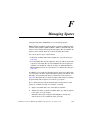
Appendix F. Managing Spares . . . . . . . . . . . . . . . . . . . . . . . . . . . . .
275
F.1
F.1.1
F.1.2
Managing Dedicated Spares . . . . . . . . . . . . . . . . . . . . . . . . . . . . . . . . 276
Adding a Dedicated Spare . . . . . . . . . . . . . . . . . . . . . . . . . . . . . . . . . . . .276
Deleting a Dedicated Spare . . . . . . . . . . . . . . . . . . . . . . . . . . . . . . . . . . .277
F.2
Enabling Dynamic Spares . . . . . . . . . . . . . . . . . . . . . . . . . . . . . . . . . . 278
F.3
F.3.1
F.3.2
F.3.3
Managing the Spare Pool . . . . . . . . . . . . . . . . . . . . . . . . . . . . . . . . . . . 280
Adding a Spare to the Spare Pool . . . . . . . . . . . . . . . . . . . . . . . . . . . . .280
Deleting a Spare from the Spare Pool . . . . . . . . . . . . . . . . . . . . . . . . .281
Displaying the Spare Pool . . . . . . . . . . . . . . . . . . . . . . . . . . . . . . . . . . . .281
Appendix G. Managing Disk Drives and Enclosures 283
xx
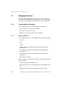
G.1
G.1.1
G.1.2
G.1.3
G.1.4
G.1.5
G.1.6
G.1.7
G.1.8
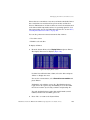
Managing Disk Drives . . . . . . . . . . . . . . . . . . . . . . . . . . . . . . . . . . . . . 284
Displaying Drive Information . . . . . . . . . . . . . . . . . . . . . . . . . . . . . . . . .284
Clearing Metadata from a Drive . . . . . . . . . . . . . . . . . . . . . . . . . . . . . . .288
Enabling and Disabling Write-back Cache . . . . . . . . . . . . . . . . . . . . .288
Displaying Disk Cache Status . . . . . . . . . . . . . . . . . . . . . . . . . . . . . . . . .290
Enabling and Disabling SMART Changes . . . . . . . . . . . . . . . . . . . . . .291
Blinking a Drive LED . . . . . . . . . . . . . . . . . . . . . . . . . . . . . . . . . . . . . . . . .292
Taking Down a Drive . . . . . . . . . . . . . . . . . . . . . . . . . . . . . . . . . . . . . . . . .292
Testing a Drive . . . . . . . . . . . . . . . . . . . . . . . . . . . . . . . . . . . . . . . . . . . . . . .293
G.2
G.2.1
G.2.2
Managing Enclosures . . . . . . . . . . . . . . . . . . . . . . . . . . . . . . . . . . . . . . 294
Setting the EMP LUN . . . . . . . . . . . . . . . . . . . . . . . . . . . . . . . . . . . . . . . . .294
Changing the Additional EMP Setting . . . . . . . . . . . . . . . . . . . . . . . . .296
DataDirect Networks EF2800 FC RAID Storage System User Guide (V 1.0)
Table of Contents
Appendix H. Configuring the EF2800 . . . . . . . . . . . . . . . . . . . . 297
H.1
H.1.1
H.1.2
H.1.3
H.1.4
H.2
H.3
H.4
H.4.1
H.5
H.6
H.7
H.8
H.9
H.10
H.11
H.12
H.13
H.13.1
H.13.2
Shutting Down and Restarting the Storage Manager Module. . . . . 298
Shutting Down and Restarting the Current SM Module . . . . . . . . 298
Shutting Down the Other SM Module . . . . . . . . . . . . . . . . . . . . . . . . . 299
Shutting Down Both SM Modules . . . . . . . . . . . . . . . . . . . . . . . . . . . . . 300
Other Controller Menu . . . . . . . . . . . . . . . . . . . . . . . . . . . . . . . . . . . . . . . 300
Changing the Date and Time. . . . . . . . . . . . . . . . . . . . . . . . . . . . . . . . 301
Configuring the Host Channels. . . . . . . . . . . . . . . . . . . . . . . . . . . . . . 303
Understanding LUNs and Viewing LUN Information . . . . . . . . . . . 305
Viewing LUN Information . . . . . . . . . . . . . . . . . . . . . . . . . . . . . . . . . . . . 306
Configuring the FC Disk Channels. . . . . . . . . . . . . . . . . . . . . . . . . . . 307
Changing the Alarm Mute Setting. . . . . . . . . . . . . . . . . . . . . . . . . . . . 308
Locking the Cache Setting. . . . . . . . . . . . . . . . . . . . . . . . . . . . . . . . . . 311
Enabling and Disabling the Battery . . . . . . . . . . . . . . . . . . . . . . . . . . 312
Changing the Utility Priority . . . . . . . . . . . . . . . . . . . . . . . . . . . . . . . . 313
Rescanning All Channels . . . . . . . . . . . . . . . . . . . . . . . . . . . . . . . . . . . 314
Pausing I/O . . . . . . . . . . . . . . . . . . . . . . . . . . . . . . . . . . . . . . . . . . . . . . 315
Restoring Default Settings. . . . . . . . . . . . . . . . . . . . . . . . . . . . . . . . . . 316
Updating Firmware . . . . . . . . . . . . . . . . . . . . . . . . . . . . . . . . . . . . . . . 316
Updating SM, SM Loader and Memory Controller Firmware . . . 317
Updating LAN Firmware . . . . . . . . . . . . . . . . . . . . . . . . . . . . . . . . . . . . . 318
Appendix I. LAN Configuration. . . . . . . . . . . . . . . . . . . . . . . . . . . . . 321
I.1
I.2
I.2.1
I.2.2
I.2.3
I.2.4
I.2.5
I.2.6
I.2.7
I.2.8
Configuring the SM for TCP/IP . . . . . . . . . . . . . . . . . . . . . . . . . . . . . . 321
Configuring the LAN Settings . . . . . . . . . . . . . . . . . . . . . . . . . . . . . . . 322
Configuring the IP Settings . . . . . . . . . . . . . . . . . . . . . . . . . . . . . . . . . . . 322
Configuring the FTP Settings . . . . . . . . . . . . . . . . . . . . . . . . . . . . . . . . . 323
Configuring the Telnet Settings . . . . . . . . . . . . . . . . . . . . . . . . . . . . . . . 324
Configuring the SNMP Settings . . . . . . . . . . . . . . . . . . . . . . . . . . . . . . . 324
Configuring the Contact Settings . . . . . . . . . . . . . . . . . . . . . . . . . . . . . 325
Configuring the HTTP Settings . . . . . . . . . . . . . . . . . . . . . . . . . . . . . . . 326
Configuring the Security Options . . . . . . . . . . . . . . . . . . . . . . . . . . . . . 327
Resetting the LAN Subsystem . . . . . . . . . . . . . . . . . . . . . . . . . . . . . . . . 328
Glossary . . . . . . . . . . . . . . . . . . . . . . . . . . . . . . . . . . . . . . . . . . . . . . . . . . . . . . . . . . . . . 329
Index . . . . . . . . . . . . . . . . . . . . . . . . . . . . . . . . . . . . . . . . . . . . . . . . . . . . . . . . . . . . . . . . . 341
DataDirect Networks EF2800 FC RAID Storage System User Guide (V 1.0)
xxi
Table of Contents
Contacting Technical Support & Shipping
Instructions . . . . . . . . . . . . . . . . . . . . . . . . . . . . . . . . . . . . . . . . . . . . . . .357
xxii
DataDirect Networks EF2800 FC RAID Storage System User Guide (V 1.0)
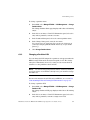
1
Introduction
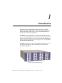
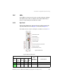
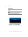
The DataDirect Networks EF2800 system is designed as a RAID
Subsystem to be used with a host system or Storage Area Network
(SAN) with a Fibre Channel (FC) connection and FC disk drives to
provide a powerful storage Subsystem.
The EF2800 storage Subsystem is a fault-tolerant RAID systems that
lets you configure FC disk drives as fault-tolerant arrays. The arrays are
presented as logical units to one or two host ports. The EF2800s have
write-back cache memory that is backed up by a battery in each EF2800
Storage Manager (SM) module.
The EF2800 systems have two fully redundant FC host ports on each
SM module that support 1-Gbit and 2-Gbit speeds and four fully
redundant FC disk ports.
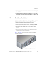
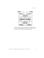
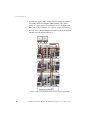
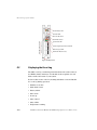
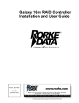
Figure 1. EF2800 System Front View
DataDirect Networks EF2800 FC RAID Storage System User Guide (V 1.0)
1
Introduction
The EF2800 includes the following features:
• Fully fault-tolerant, modular design
• Sequential data transfers from disk arrays at nearly 700 MB/sec
sustained
• Greater than 50,000 I/O operations per second (IOPS) capability
• Operating system independent, no special software or drivers
required
• Two 1-Gbit/2-Gbit Fibre Channel host ports on each LRC I/O
module.
• Fibre Channel host interface supporting Fibre Channel-Arbitrated
Loop (FC-AL), point-to-point, and switched fabric
• Four redundant 1-Gbit/2-Gbit FC disk ports
• Support for up to 248 FC devices organized in up to 32 arrays, with
16 partitions per array up to a total of 128 Logical Unit Numbers
(LUNs)
• Configuration and management using a local area network (LAN)
(10/100baseT) connection
• Support for 512Mb or 1024Mb cache memory on each LRC I/O
module using standard double data rate (DDR; DDR 266
supported) Dual Inline Memory Modules (DIMMs). DIMMs must be
qualified.
• Redundant power, AC, and cooling
• Built to fit into 3U-high (5.25" [13.35 cm]), 19" (48.26 cm) rack
• Support for RAID levels 0, 1, 3, 4, 5, 10, 50, and just a bunch of disks
(JBOD)
• Online capacity expansion allowing reconfiguration without
interruptions
• Advanced disk drive utilities, array verification and recovery, and
global spares
• Embedded Configuration Application Programming Interface
(CAPI) for programmatic configuration and management of the
EF2800
• Replacement of major system modules during online operation
2
DataDirect Networks EF2800 FC RAID Storage System User Guide (V 1.0)
Introduction
• Software upgrades either in-band over FC or out-of-band using RS232 or Ethernet
• Continuous runtime monitoring for warnings for out-of-spec CPU
temperatures, controller voltages, battery failures, fan failures, and
internal errors
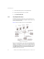
1.1
The Enclosure Core Product
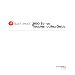
The EF2800 design concept is based on a subsystem together with a set
of plug-in modules. The EF2800 enclosure as supplied comprises:
• Chassis and backplane with integral Operators Panel
• Power Supply/Cooling plug-in modules, auto-ranging, 475W, AC
• FC-AL Drive Carrier Modules and associated dummy carrier
modules
• FC-AL LRC 2Gb/s Input/Output Modules with integrated RAID
controllers, known as Storage Managers
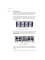
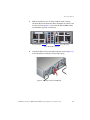
Figure 1 and Figure 2 show the front and rear views of an EF2800
enclosure respectively.
Figure 2. EF2800 System Rear View
DataDirect Networks EF2800 FC RAID Storage System User Guide (V 1.0)
3
Introduction
1.1.1
Enclosure Chassis
The chassis consists of a sheet metal enclosure assembly containing a
backplane PCB and module runner system. This chassis assembly also
includes an integral Operators (Ops) Panel mounted at the rear.
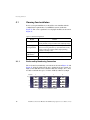
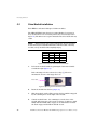
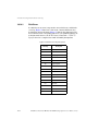
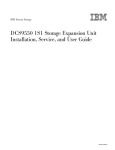
The chassis assembly contains 16 drive bays at the front, each of which
accommodates a plug-in drive carrier module (Figure 3). The 16 drive
bays are arranged in 4 rows of 4 drives. Bay numbers are defined by
column/row.
Column
Row
1
1
Drive 0*
2
Drive 1
3
4
Drive 2
Drive 3
2
Drive 4
Drive 5
Drive 6
3
Drive 8
Drive 9
Drive 10
Drive 11
4
Drive 12
Drive 13
Drive 14
Drive 15*
Drive 7
*SES Drives (there must be a drive present in Bays 1/1 and 4/4
to enable SES communications to operate)
Figure 3. Drive Locations at the Front
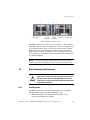
At the rear, there are 5 module bays to house two power supply/cooling
modules, two LRC I/O modules and the integral Ops panel (Figure 4).
The Backplane PCB provides logic level signal and low voltage power
distribution paths.
PSU/Cooling 1
Storage
Manager B
Storage
Manager A
Ops Panel
PSU/Cooling 2
Figure 4. Module Locations at Rear
The 4 × 4 chassis is fitted with 19 inch Rack mounting features which
enables it to be fitted to standard 19 inch racks and uses 3EIA units of
rack space.
4
DataDirect Networks EF2800 FC RAID Storage System User Guide (V 1.0)
Introduction
1.2
The Plug-in Modules
An EF2800 Enclosure requires one or more of the following modules
for normal operation.
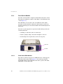
1.2.1
Power Supply/Cooling Module
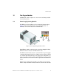
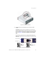
The EF2800 enclosure utilizes two Power Supply/Cooling modules
(Figure 5). PSU (power supply unit) voltage operating ranges are
nominally 115V or 230V AC, selected automatically.
Power
Supply
AC
Input
Fail
Fan
Fault
DC
Output
Fail
Figure 5. Power Supply/Cooling Module and LEDs
Four LEDs mounted on the front panel of the Power Supply/Cooling
Module indicate the status of the PSU and the fans.
The EF2800 system must always be operated with two power supply/
cooling modules installed. The two modules operate together so that if
one fails the other maintains the power supply and cooling while you
replace the faulty unit. The faulty module will still be providing cooling
for the system so do not remove it until a replacement is available for
fitting.
Module replacement should only take a few minutes to perform but
must be completed within 5 minutes from removal of the failed module.
DataDirect Networks EF2800 FC RAID Storage System User Guide (V 1.0)
5
Introduction
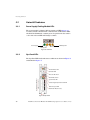
1.2.2
Operators Panel
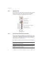
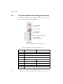
The Ops Panel (Figure 6) provides the enclosure with a micro controller
which is used to monitor and control all elements of the EF2800
enclosure. It is supplied as an integral part of the enclosure.
Invalid Address LED
Power On LED
Enclosure ID Switch
Configuration Switches
Alarm Mute Switch
System Fault LED
1
2
3
4
5
6
7
8
9
10
11
12
PSU/Cooling/Temperature Fault LED
2Gb Link Speed LED
Hub Mode LED (not used)
ON
OFF
Figure 6. Ops Panel
1.2.2.1
Ops Panel Status LED Indicators and Switches
The Ops Panel includes status LED indicators which show the status
for all modules, an Audible Alarm which will be activated when a fault
state is present, an Alarm Mute switch, and a thumb wheel SEL_ID
address range selector switch (Figure 6).
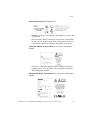
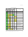
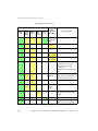
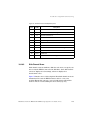
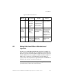
The Ops Panel configuration switch functions are shown in Figure 7.
NOTE: Switch settings are only read at Power On. The EF2800 enclosure
ID must always be set to select ID1.
CAUTION: All mandatory settings must be observed in order for the
EF2800 system to function correctly.
6
DataDirect Networks EF2800 FC RAID Storage System User Guide (V 1.0)
Introduction
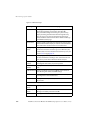
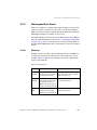
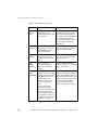
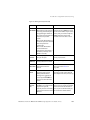
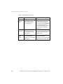
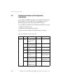
Figure 7. Ops Panel Switch Functions (Default settings for usage at 2Gb/s)
Switch
No.
1
Loop Select,
Dual (2x8)
2
Not Used
3
Not Used
4
Not Used
5&6
Not Used
7&8
Drive Loop Speed
Select
9 & 10
1.2.3
Off
SOFT SELECT
12
Not Used
Definition
LRC operates on two loops of 8
drives (Mandatory)
Note: on expansion enclosures this must be set On.
Drive Addressing
Mode Selection
11
NOTE:
Recommended
Setting
Function
Sw7
Sw8
On
Off
Force 2Gb/s
Off
Off
Force 1Gb/s
Sw9
Sw10
On
Off
On
Mode 2, 2x8 mode.
(Mandatory)
Select Functions using the
hardware switches
To set Host 1Gb use the Ethernet connected configurator.
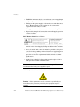
LRCI/O Module (FC-AL)
The EF2800 enclosure includes two Loop Resiliency Circuit (LRC) I/O
modules with integrated RAID controller, known as Storage Managers
(SM) modules (Figure 8). The FC-AL backplane incorporates two
independent loops formed by Port Bypass Circuits within the LRC I/O
modules.
The plug-in SM modules have been designed for integration into an
EF2800 system, utilizing FC-AL interfacing with the host computer
system.
Processors housed on the I/O modules provide enclosure management
and interface to devices on the backplane, PSU, LRC, and Ops Panel, to
DataDirect Networks EF2800 FC RAID Storage System User Guide (V 1.0)
7
Introduction
monitor internal functions. These processors operate in a master slave
configuration to allow failover.
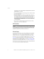
Figure 8. I/O Module
Expansion Port 1
Expansion Port 2 Signal Good LED
Expansion Port 1 Signal Good LED
Expansion Port 2
RJ45 Ethernet Connection (not to be
to telecommunications networks)
System LED
Battery Fail LED
Host Port 1
Cache Active LED
RAID Activity LED
Host Port 1 Signal Good LED
Host Port 0 Signal Good LED
Host Port 0
Enclosure Services Interface (ESI) RS232
RS232 (RAID)
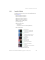
Figure 9. Connectors and LEDs on I/O Module
8
DataDirect Networks EF2800 FC RAID Storage System User Guide (V 1.0)
Introduction
The module incorporates the following status LED indicators (Figure 9):
• Expansion Port 1 Rx Good (Green)
• Expansion Port 0 Rx Good (Green)
• System Ready (Green)
• Battery Fault (Amber)
• Cache Active (Green)
• RAID Controller Activity
• Host Port 1 Signal Good (Green)
• Host Port 0 Signal Good (Green)
NOTE: Fitting of a RAID controller to the LRC module is a factory only
operation.
!
Do not attempt to lift the enclosure by means of the
extended I/O module.
Warning
The Storage Manager module operates at 1 or 2 Gb.
Two external ports for expansion to further enclosures are provided by
SFP connectors. Two external ports to the host controllers are
provided from Small Form Factor (SFP) GBIC modules, auto-bypass at
the output ports is also provided.
An RJ45 10/100 Base T Ethernet controller management port is
provided on the LRC board, interfacing to the controller through 2
RS232 serial and GPIO lines.
CAUTION: The RJ45 Ethernet connector on the LRC module must not be
connected to telecommunications networks.
The SM module also incorporates a standby Li-ion battery pack,
72 hours cache hold up time (512Mb). The battery cell has thermal
protection. Battery cells cannot be replaced in the field.
DataDirect Networks EF2800 FC RAID Storage System User Guide (V 1.0)
9
Introduction
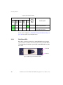
1.2.4
Drive Carrier Module
The Drive Carrier module comprises a hard disk mounted in a carrier.
Each drive bay will house a single 1.0-inch high, 3.5-inch disk drive in its
carrier (Figure 10).
Each disk drive is enclosed in a die-cast aluminum carrier which
provides excellent thermal conduction, radio frequency and electromagnetic induction protection and affords the drive maximum physical
protection.
The front cap also supports an ergonomic handle which provides the
following functions:
• Camming of carrier into and out of drive bays
• Positive “spring loading” of the drive/backplane connector
• An anti-tamper lock operated by a torx socket type key
Status LED
Fault LED
Figure 10. Drive Carrier Module
1.2.4.1
Drive Status LED Indicators
Each drive module incorporates two LED indicators, a Status (green)
LED and a Fault (amber) LED (Figure 10). In normal operation the
Status LED will be ON and will flash as the drive operates. The Fault
LED will be on if the drive fails.
10
DataDirect Networks EF2800 FC RAID Storage System User Guide (V 1.0)
Introduction
1.2.4.2
Anti-Tamper Locks
Anti-tamper locks are fitted in the drive carrier handles (Figure 11). The
lock can be accessed through the small cutout in the latch section of the
handle, using a T10 Security Torx type bit. These locks are provided to
disable the normal “pinch” latch action of the carrier handle.
NOTE : Do NOT overtighten the anti-tamper lock!
Indicator Aperture
Anti-Tamper Lock
Turn key
clockwise
to lock
Turn key
counter-clockwise
to unlock
Figure 11. Anti-Tamper Lock on Drive Carrier Module
1.2.5
Dummy Carrier Modules
Dummy carrier modules are provided for fitting in all unused drive
bays. They are designed as integral drive module front caps with
handles and must be fitted to all unused drive bays to maintain
balanced airflow.
!
Warning
Operation of the Enclosure with ANY modules missing
will disrupt the airflow and the drives will not receive
sufficient cooling. It is ESSENTIAL that all apertures are
filled before operating the unit. Dummy Carriers are
available for this purpose.
DataDirect Networks EF2800 FC RAID Storage System User Guide (V 1.0)
11
Introduction
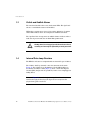
1.3
Visible and Audible Alarms
The functional modules have associated status LEDs. The Ops Panel
shows a consolidated status for all modules.
LEDs show constant green for good or positive indication. Constant
amber LEDs indicate there is a fault present within that module.
The Ops Panel also incorporates an audible alarm to indicate when a
fault state is present and also an Alarm Mute push-button.
!
The Ops Panel is an integral part of the enclosure chassis
assembly and can only be replaced by trained personnel.
Warning
1.4
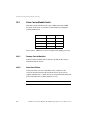
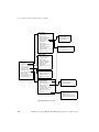
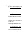
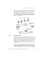
Internal Drive Loop Structure
The EF2800 enclosure is configured with two internal loops of 8 drives.
The 16 drive dual loop internal connection structure is shown in
Figure 12. Two plug-in, Loop Redundancy Circuit SM modules are
mounted in rear Bays 3 and 4 (Figure 4); these contain Port Bypass
Circuits (PBC) that provide loop resiliency in the event of unplugged or
failing drives.
NOTE: Figure 12 shows the logical routing of the EF2800 FC-AL
interface through the drive bays, this figure does not represent the
physical wiring of the enclosure.
12
DataDirect Networks EF2800 FC RAID Storage System User Guide (V 1.0)
Introduction
Figure 12. EF2800 Internal Drive Loop Structure
Each FC loop is routed through an independent SM module fitted in the
rear of the enclosure. Either of these may be removed while the other
is operating, thus providing fully redundant FC operation.
DataDirect Networks EF2800 FC RAID Storage System User Guide (V 1.0)
13
This page intentionally left blank.
14
2
Getting Started
In this chapter, you are shown how to install your EF2800 RAID
enclosure (and plug-in modules) into an industry standard 19-inch rack
cabinet.
NOTE: The installation, configuration, and use of the EF2800 RAID
system in all but the most basic of environments requires certain expertise
on the part of the user. Because there are many connections and
configuration options involving host platforms, host bus adapters (HBAs),
storage enclosures, disk drive devices, and applications, only general
guidelines are included in this document. No in-depth discussion of
integration of the EF2800 is included here due to the high level of expertise
required on the part of the integrator and the level of support that may be
needed from your supplier.
Do not operate the EF2800 system until the ambient temperature is
within the specified operating range (see Appendix A). If the drives
have been recently installed ensure they have had time to acclimatize
before operating them.
CAUTION: When connecting up the EF2800 system, use the power cords
supplied or ones which match the specification quoted in Section A.1.5.
DataDirect Networks EF2800 FC RAID Storage System User Guide (V 1.0)
15
Getting Started
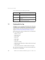
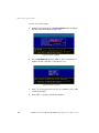
2.1
Planning Your Installation
Before you begin installation you should become familiar with the
configuration requirements of your EF2800 system, detailed in
Figure 13. The correct positions of each plug-in modules are shown in
Figure 15.
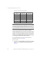
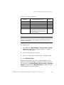
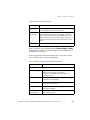
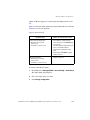
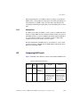
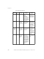
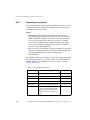
Figure 13. EF2800 Configuration
Module
2.1.1
Location
Drive Bays
ALL drive bays must be filled with either a drive module or a
dummy module, no bays should be left completely empty
Power Supply/
Cooling Modules
Two Power Supply/Cooling modules are required. Full
power and cooling redundancy is provided while a faulty
module is replaced. Install the Power Supply/Cooling
modules in rear Bays 1 & 5.
Storage Manager
(I/O) Modules
Installed in rear Bays 3 and 4
Ops Panel
Rear Bay 2 (integral part of chassis assembly)
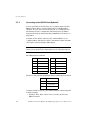
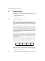
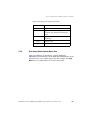
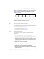
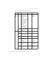
Enclosure Bay Numbering Convention
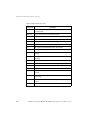
The enclosure bay numbering conventions are shown in Figure 14 and
Figure 15. A Bay is defined as the space required to house a single 1.0"
high 3.5 inch disk drive in its carrier module. For example, an 1 × 4 bay
module would take the space of 1 drive width by 4 drive bays high.
Column
Row
1
1
2
3
4
Drive 0*
Drive 1
Drive 2
Drive 3
2
Drive 4
Drive 5
Drive 6
Drive 7
3
Drive 8
Drive 9
Drive 10
Drive 11
4
Drive 12
Drive 13
Drive 14
Drive 15*
Figure 14. Drive Locations at Front
16
DataDirect Networks EF2800 FC RAID Storage System User Guide (V 1.0)
Getting Started
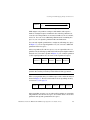
5
PSU/Cooling 1
4
Storage
Manager B
3
2
Storage
Manager A
1
Ops Panel
PSU/Cooling 2
Figure 15. Module Locations at Rear
The EF2800 system is housed in a 4 × 4 enclosure, i.e. 4 bays wide by
4 bays high. The front bays are numbered 1 to 4 from left to right, when
viewed from the front, and 1 to 4 from top to bottom. Drive Carrier
Module locations are identified from a matrix of the top and side
numbers. The rear bays are numbered 1 to 5 from right to left, when
viewed from the rear. Module locations are identified by a matrix of the
top and side numbers.
NOTE : For proper operation of SES (SCSI Enclosure Services), drive
module must always be installed in bays 1/1 (drive 0) and 4/4 (drive 15).
2.2
Rack-Mounting the Enclosure
!
Warning
2.2.1
Ensure that you have checked and fitted a suitable antistatic wrist or ankle strap and observe all conventional
ESD precautions when handling EF2800 modules and
components. Avoid contact with backplane components
and module connectors.
Pre-Requisites
The EF2800 enclosure is designed for installation into an industry
standard 19-inch cabinet capable of holding the unit.
• Minimum depth 20.12" (511mm) from front flange to rear
metalwork (excludes rear cabling)
DataDirect Networks EF2800 FC RAID Storage System User Guide (V 1.0)
17
Getting Started
• Weight of up to 81.4lbs (37kg), dependent upon configuration per
enclosure
• A minimum gap of 1" (25mm) clearance between the rack cover
and front of drawer; and 2" (50mm) rear clearance between rear of
drawer and rear of rack is recommended in order to maintain the
correct air flow around the enclosure.
• The rack should present a maximum back pressure of 5 Pascals
(0.5mm water gauge). A vented rear door or no door at all are the
recommended configurations.
2.2.2
Unpacking the EF2800
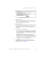
To unpack the EF2800:
1.
Place the shipping container on a flat, clean, stable surface.
2.
Carefully remove the EF2800 and verify the contents against the
packing list.
3.
Remove the foam from the sides of the EF2800 and remove it from
the plastic bag.
4.
Save the original shipping container and packing materials in case
future reshipment is necessary.
5.
Visually inspect the EF2800 and notify your freight carrier
immediately of any damage.
You can hot swap each module as long as the other module of the pair
is operating properly.
CAUTION: Do not leave any slots open on the EF2800 family of products.
If you need to replace a module, leave the old module in place until you
have the replacement. Leaving a slot open adversely affects the airflow and
may cause the unit to overheat.
18
DataDirect Networks EF2800 FC RAID Storage System User Guide (V 1.0)
Getting Started
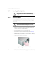
2.2.3
Installing the Enclosure in Rack
CAUTION: The EF2800 enclosure with all its component parts installed is
too heavy for easy installation into a rack cabinet. The following
procedures describe the installation of the enclosure and highlights any
critical co-requisite requirements and good handling practices which we
encourage you to follow so as to ensure that a successful installation is
achieved in the easiest manner.
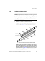
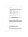
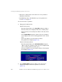
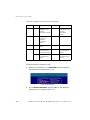
1.
Install the two rail/support assemblies in the rack.
Using three #10 screws, washers, and nuts, assemble the rail
inside the support (Figure 16). Only finger-tighten the screws.
Rail
#10 Nut (3)
#10 Washer (3)
#10 Screw (3)
Support
Figure 16. Assembling Rail to Support (Left Hand Assembly)
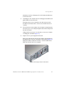
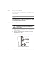
Adjust the length of the rail/support assembly to fit the depth of
the rack. Then tighten the three screws and nuts on the assembly.
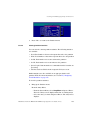
Fasten the assembly to the rack frame using four #10 screws, two
in front and two in rear (Figure 17). Make sure you leave enough
space above the rail/support assembly to accommodate the
enclosure. Then tighten all screws.
DataDirect Networks EF2800 FC RAID Storage System User Guide (V 1.0)
19
Getting Started
Similarly, assemble and install the rail/support assembly in the
other side of the rack frame, making sure that the two rails are
level (horizontally) in the rack.
Rear of Rack
#10 Screw (2)
Front of Rack
Screw Holes for Securing
Rear of Chassis
#10 Screw (2)
Figure 17. Fastening Rail/Support Assembly to Rack (Left Hand Assembly)
2.
To reduce the weight of the unit, it is best to remove the power
supplies and drive modules from the enclosures.
To remove a power supply, squeeze the two latches on the handle
together and open the handle to cam the module out of the
enclosure.
To remove a drive module, press the latch in the handle towards
the right to release the handle (Figure 18).
Press Latch
Figure 18. Latch Operation on Drive Module
Then swing open the handle and pull the module out of the bay. If
the anti-tamper lock is activated, see Step [5] on page 27 for
20
DataDirect Networks EF2800 FC RAID Storage System User Guide (V 1.0)
Getting Started
information on how to disengage the lock. Dummy modules may
be left in the slots.
3.
Carefully place the chassis on the two rail/support assemblies and
push it all the way into the rack.
If in doubt about correct orientation, the drive bays (at front)
should have their black drive connectors toward the bottom of
each bay.
4.
Secure the front of the chassis to the rack frame by inserting four
#10 screws (two on each side) through the holes in the flanges and
into the rack frame.
Using four #10 screws (two on each side), secure rear of chassis
to rail/support assemblies (Figure 17).
5.
Replace the two power supplies in the back.
Insert one module into the left most bay and the other module into
the right most bay. Note the orientation of the modules (Figure 19).
Swing the handle towards the module to cam the module home.
Make sure that the latches are engaged.
Figure 19. Power Supply Locations in Rear Panel
DataDirect Networks EF2800 FC RAID Storage System User Guide (V 1.0)
21
Getting Started
2.3
Power Supply/Cooling Module Installation
Install in the rear of the enclosure in bays 1 and 5.
!
Warning
2.3.1
Do not remove covers from the Power Supply/Cooling
(PSU) module. Danger of electric shock inside. Return the
PSU to your supplier for repair.
Parts Check List
• Two Power Supply/Cooling Modules
2.3.2
Procedure
NOTE: PSU2 (RH rear bay) must be fitted “upside-down” as shown in
Figure 15.
1.
Check for damage, especially to the rear connector on the supply.
CAUTION:Handle the module carefully and avoid damaging the
connector pins. Do not install the module if any pins appear to be bent.
2.
Squeeze to open both latches and leave the handle in open
position (Figure 20).
Figure 20. Power Supply Module with Handle in Open Position
22
DataDirect Networks EF2800 FC RAID Storage System User Guide (V 1.0)
Getting Started
3.
Slide the module into the enclosure. The modules should be
installed in bays 1 and 5, as shown in Figure 21.
NOTE: Install the Power Supply/Cooling module in the right hand bay
(Rear Bay 1) of the enclosure in an “upside down” orientation.
PSU 2
PSU 1
Figure 21. Module Locations
4.
Cam the module home by manually closing the handle. A click
should be heard as the handle latches engage (Figure 22).
Figure 22. Installing an AC Power Supply Cooling Module
DataDirect Networks EF2800 FC RAID Storage System User Guide (V 1.0)
23
Getting Started
2.4
Controller I/O Module Installation
!
Do not attempt to lift the enclosure by means of the
extended SM modules.
Warning
2.4.1
Parts Check List
• 2 Controller I/O Modules or,
• 1 Controller I/O Module with 1 Blank I/O module
NOTE: The enclosure may be configured with either one or two
Controller modules. If only one Controller is fitted it must be installed in
rear bay 4 (Controller B location as shown in Figure 15 on page 17) and a
Blank I/O module fitted in the unused bay.
2.4.2
Procedure
1.
Check for damage especially to the interface connector, do not
install if any pins are bent.
2.
Squeeze to open the latches (Figure 23).
Figure 23. Controller Module Latch Operation
24
DataDirect Networks EF2800 FC RAID Storage System User Guide (V 1.0)
Getting Started
3.
Slide the module into the enclosure until the latches engage
automatically. The modules should be installed in rear bays 3 and
4 of the enclosure (Figure 24). Note that the LH and RH modules
are installed in opposite orientations.
Storage Manager B
Storage Manager A
Figure 24. Module Locations
4.
Cam the module home by manually closing the latches (Figure 25).
A click should be heard as the latches fully engage.
Figure 25. Installing a Controller I/O Module
DataDirect Networks EF2800 FC RAID Storage System User Guide (V 1.0)
25
Getting Started
2.5
Drive Module Installation
Each EF2800 enclosure holds up to 16 drive modules.
The SES (SCSI Enclosure Services) requires disks to be present in
bays 1/1 and 4/4 of each enclosure (indicated by shaded background in
Figure 26). The drives are not pre-formatted and can be inserted in any
order.
NOTE: When planning your system configuration, please remember
that all drive bays must be filled with either a drive module or dummy
module, no bays should be left completely empty.
Drive 0
Drive 15
Figure 26. Drive Bays for SES Communication Paths
1.
Release the module handle by pressing the latch in the handle
towards the right (Figure 27).
If the anti-tamper lock is activated, see Step [5] below for
information on how to disengage the lock.
Press Latch
Figure 27. Opening the Drive Module Handle
26
2.
Insert the module into the bay (Figure 28).
3.
Slide the module, gently, all the way into the bay until it is stopped
by the camming lever on the right of the module.
4.
Cam the module home - the camming foot on the base of the
module will engage into a slot on the enclosure. Continue to push
firmly until the handle fully engages. A click should be heard as
the latch engages and holds the handle closed.
DataDirect Networks EF2800 FC RAID Storage System User Guide (V 1.0)
Getting Started
Figure 28. Inserting the Drive Module
5.
You may activate the anti-tamper locks on the drive module
handles.
Carefully insert the lock key provided into the cutout in the
handle and align it with the socket. Rotate the key in a clockwise
direction until the lock indicator is visible in the aperture beside
the socket (Figure 29). Do not over-tighten the anti-tamper
lock.
To de-activate, rotate the key in a counter-clockwise direction
until the lock indicator is no longer visible in the aperture beside
the socket.
Indicator Aperture
Anti-Tamper Lock
Turn key
clockwise
to lock
Turn key
counter-clockwise
to unlock
Figure 29. Activating the Anti-Tamper Lock
DataDirect Networks EF2800 FC RAID Storage System User Guide (V 1.0)
27
Getting Started
2.6
Verify Configuration Switch Settings on Ops Panel
Verify that the settings for the configuration switches on the Ops panel
(Figure 30) are the same as listed in Figure 31.
Invalid Address LED
Power On LED
Enclosure ID Switch
Configuration Switches
Alarm Mute Switch
System Fault LED
1
2
3
4
5
6
7
8
9
10
11
12
PSU/Cooling/Temperature Fault LED
2Gb Link Speed LED
Hub Mode LED (not used)
ON
OFF
Figure 30. Configuration Switches on Ops Panel
Figure 31. Configuration Switch Settings on Ops Panel
Switch No.
28
Function
Correct Setting
1
Loop select, Dual (2x8)
Off (mandatory)
2
Not used (Note: This must be set to ON for expansion enclosures.)
3
Not used
4
Not used
5&6
Not used
7&8
Drive loop speed select
9 & 10
Drive addressing mode select
11
Soft select
12
Not used
7 On, 8 Off (Force 2Gb/s)
9 On, 10 Off (Mode 2)
On
DataDirect Networks EF2800 FC RAID Storage System User Guide (V 1.0)
Getting Started
2.7
Connecting the Enclosure to FC Host and Disk Ports
The (I/O) interface module provides a Fibre Channel interface via small
form-factor pluggable connection (SFPs) that can be either copper
HSSDC-2 connectors for copper or optical (LC optical cable)
connection. Copper (1M max.) SFP to SFP patch cables are also
supported (for enclosure to enclosure connection only).
Each I/O or Loop Resiliency Circuit board houses Port Repeater chips
that re-drive the Fibre Channel signals. Each of the LRC I/O boards also
houses a number of Port Bypass circuits. The function of these circuits
is to bypass the loop connections to empty drive bays or any disk drive
which is not operating correctly
NOTE: There are no external terminators required with Fibre Channel
architecture and any drive may be hot plugged during operation.
• You can connect the EF2800 directly to one or more FC HBAs or to
a FC switch or hub (Figure 32). Each Storage Manager has two FC
host ports.
Host 0 Loop 1
Host 1 Loop 1
Host 0 Loop 2
Host 1 Loop 2
Figure 32. Connecting the EF2400 Enclosure
• You can attach FC disk drives to all of the EF2800’s FC disk ports.
• You can connect up to 248 FC devices to the EF2800, including the
16 internal hard drives.
DataDirect Networks EF2800 FC RAID Storage System User Guide (V 1.0)
29
Getting Started
• You must use approved FC components (for example, standard 3.3volt small form-factor pluggable [SFPs] and FC cable, either
optical or copper) that you can purchase from your supplier. The
SFP connector is available in two versions: Copper and Optical.
• You can connect additional disk enclosures by daisy-chaining them
using the patterns shown in Figure 33.
Figure 33. Connecting the Expansion Enclosures to EF2800 (2x8 Mode)
30
DataDirect Networks EF2800 FC RAID Storage System User Guide (V 1.0)
Getting Started
2.7.1
Expansion Enclosures
Multiple enclosures are connected together by using SFP to SFP
approved patch cables, or SFPs and optical LC to LC cables. Up to 14
expansion enclosures can be connected to the EF2800 (Figure 33).
NOTE: Loss of power to any enclosure within such a loop will cause the
loop to fail.
Power Up
Ensure that all attached JBOD enclosures are fully powered up and all
hard drives have spun up prior to powering on the EF2800 enclosure.
Power Down
Ensure that the EF2800 enclosure is powered down prior to powering
down the JBOD enclosures.
2.7.2
Enclosure Device Addressing
The EF2800 enclosure supports 15 address ranges (1 to 9, A to F). The
thumb wheel switch on the Ops panel is used to select the SEL_ID base
address.
Figure 34 below shows the device addresses for the drive slots, with
respect to different enclosure ID settings. Each table cell represents a
drive slot on the enclosure (when viewing from front). Up to 14
expansion enclosures can be daisy-chained to the EF2800 and each
enclosure must have a unique enclosure ID.
NOTE: There must be a drive present in Bay 1/1 or 4/4 to enable SES
Communications to operate. Installing drives in both of these bays will
provide redundant SES communication paths.
DataDirect Networks EF2800 FC RAID Storage System User Guide (V 1.0)
31
Getting Started
Figure 34. Device Addressing (Mode 2)
Device Address for Each Drive Slot
(x-y) indicates Loop and SEL_ID
Enclosure ID=1
Enclosure ID=2
Enclosure ID=3
Enclosure ID=4
Enclosure ID=5
Enclosure ID=6
Enclosure ID=7
32
1-0
1-4
2-7
2-3
1-1
1-5
2-6
2-2
1-2
1-6
2-5
2-1
1-3
1-7
2-4
2-0
1-8
1-12
2-15
2-11
1-9
1-13
2-14
2-10
1-10
1-14
2-13
2-9
1-11
1-15
2-12
2-8
1-16
1-20
2-23
2-19
1-17
1-21
2-22
2-18
1-18
1-22
2-21
2-17
1-19
1-23
2-20
2-16
1-24
1-28
2-31
2-27
1-25
1-29
2-30
2-26
1-26
1-30
2-29
2-25
1-27
1-31
2-28
2-24
1-32
1-36
2-39
2-35
1-33
1-37
2-38
2-34
1-34
1-38
2-37
2-33
1-35
1-39
2-36
2-32
1-40
1-44
2-47
2-43
1-41
1-45
2-46
2-42
1-42
1-46
2-45
2-41
1-43
1-47
2-44
2-40
1-48
1-52
2-55
2-51
1-49
1-53
2-54
2-50
1-50
1-54
2-53
2-49
1-51
1-55
2-52
2-48
DataDirect Networks EF2800 FC RAID Storage System User Guide (V 1.0)
Getting Started
Figure 34. Device Addressing (Mode 2)
Enclosure ID=8
Enclosure ID=9
Enclosure ID=A
Enclosure ID=B
Enclosure ID=C
Enclosure ID=D
Enclosure ID=E
Enclosure ID=F
1-56
1-60
2-63
2-59
1-57
1-61
2-62
2-58
1-58
1-62
2-61
2-57
1-59
1-63
2-60
2-56
1-64
1-68
2-71
2-67
1-65
1-69
2-70
2-66
1-66
1-70
2-69
2-65
1-67
1-71
2-68
2-64
1-72
1-76
2-79
2-75
1-73
1-77
2-78
2-74
1-74
1-78
2-77
2-73
1-75
1-79
2-76
2-72
1-80
1-84
2-87
2-83
1-81
1-85
2-86
2-82
1-82
1-86
2-85
2-81
1-83
1-87
2-84
2-80
1-88
1-92
2-95
2-91
1-89
1-93
2-94
2-90
1-90
1-94
2-93
2-89
1-91
1-95
2-92
2-88
1-96
1-100
2-103
2-99
1-97
1-101
2-102
2-98
1-98
1-102
2-101
2-97
1-99
1-103
2-100
2-96
1-104
1-108
2-111
2-107
1-105
1-109
2-110
2-106
1-106
1-110
2-109
2-105
1-107
1-111
2-108
2-104
1-112
1-116
2-119
2-115
1-113
1-117
2-118
2-114
1-114
1-118
2-117
2-113
1-115
1-119
2-116
2-112
DataDirect Networks EF2800 FC RAID Storage System User Guide (V 1.0)
33
Getting Started
2.7.3
Connecting to the RS-232 Port (Optional)
You can optionally use the RS-232 port to configure and monitor the
EF2800 system using a computer with a VT-100 or ANSI terminal
emulator. You can connect to the RS-232 port on each SM. For more
information about the configuration and management capabilities
using the RS-232 port and the Disk Array Administrator software, see
Appendix C.
You must use the RS-232 cable that came with the EF2800 or one
configured like it. The RS-232 cable is a standard 6-conductor, flatline
cable with a 3.5mm jack plug to DB9 adaptor.
NOTE: Not all configurations of the EF2800 are supplied with RS232
cables, you can purchase then separately from your supplier if required.
The DB9 pinout is as follows:
Pin
Function
Pin
Function
1
No connection
6
No connection
2
Receive (RX)
7
No connection
3
Transmit (TX)
8
No connection
4
No connection
9
No connection
5
Ground
The RJ-11 cable pinout is straight through (not null modem) as follows:
Pin
Function
1
Ground
2
Transmit (TX)
3
Receive (RX)
Configure the RS-232 port in your terminal emulator software using the
following settings:
• Baud rate: 9600, 19200, 38400, 57600, or 115200; 115200 is the
EF2800’s default
34
DataDirect Networks EF2800 FC RAID Storage System User Guide (V 1.0)
Getting Started
• Data Bits: 8
• Stop Bits: 1
• Parity: None
• Flow Control: None or software Xon/Xoff
To connect to the RS-232 port:
2.7.4
1.
Be sure the EF2800 is turned off.
2.
Using the RS-232 cable that came with the EF2800, connect the
jack plug end of the cable to the RS-232 serial port on one of the
SMs.
3.
Connect the DB-9 adapter to the serial (COM) port on the
computer that will monitor and configure the EF2800.
4.
Connect the other end of the RS-232 cable to the DB-9 adapter.
5.
Repeat steps 2 through 4 on the other SM.
Connecting to the Ethernet Port
CAUTION: The RJ45 Ethernet connector on the LRC module must not be
connected to telecommunications networks.
You use the Ethernet (10/100BaseT) port to configure and manage the
EF2800. This lets you manage the EF2800 from a remote computer that
is connected to your LAN. The EF2800’s default IP address is 10.0.0.1.
NOTE: To comply with radiated emissions requirements, you must use
a shielded Ethernet cable that has a properly terminated connection on
the end that connects to your network (the EF2800 connector is properly
terminated).
DataDirect Networks EF2800 FC RAID Storage System User Guide (V 1.0)
35
Getting Started
To connect to the Ethernet port:
1.
Connect one end of the Ethernet cable (RJ-45) to the Ethernet
port on one of the SM modules.
Note that you must use shielded Ethernet cable.
2.
Connect the other end of the Ethernet cable to a network hub,
controller, or other network connection.
For information about configuring the EF2800 to use the Ethernet
port, see Section 3.2, "Configuring the EF2800 for TCP/IP" on
page 45.
3.
Repeat steps 1 and 2 on the other SM module.
You are now ready to connect the power cables.
2.8
Powering On the Enclosures
2.8.1
Grounding Checks
Perform these checks to ensure that a safe grounding system is
provided.
• If a rack distribution system is being used.
- Ensure power is removed from the rack.
- Connect the EF2800 power cord to the rack distribution and the
enclosure.
• If a direct connection is made with the EF2800 power cord, ensure
that it is connected to the enclosure.
!
Warning
Some electrical circuits could be damaged if external
signal cables or power control cables are present during
the grounding checks.
• Check for continuity between the earth pin of the IEC 320
connector on one of the Power Supply/Cooling modules and any
exposed metal surface of the EF2800 enclosure.
36
DataDirect Networks EF2800 FC RAID Storage System User Guide (V 1.0)
Getting Started
2.8.2
Powering On
Before powering up your EF2800 enclosure please ensure that all the
modules are firmly seated in their correct bays and that blank modules
are installed in any unused bays.
1.
Attach the power cords to the Power Supply/Cooling Modules.
For maximum redundancy, connect the two power cords on
EF2800 (and expansion enclosures) to two different AC power
circuits.
2.
Turn on the switch on all Power Supply/Cooling modules. Verify
that the PSU LEDs are green.
If expansion enclosures are connected, turn on the expansion
enclosures first, then the EF2800.
3.
The enclosure(s) will go through the power up sequence. On the
Ops Panel, the audible alarm beeps once, all LEDs flash for
7 seconds then the alarm double beeps.
4.
Check that the Power LEDs on the Ops panels are green.
NOTE: All LEDs on the Ops Panel should be lit green at power up to
indicate that the system is functioning correctly. If any show amber then a
problem exists and the procedure in Chapter 10, "Troubleshooting and
Problem Solving" on page 141 should be followed.
5.
The drives will automatically be spun up in sequence. Wait until all
drives are spun up and ready which is indicated by a green Status
(upper) LED on the drive.
6.
Refer to Chapters 3, 4, and 5 for information on how to configure
the array.
DataDirect Networks EF2800 FC RAID Storage System User Guide (V 1.0)
37
Getting Started
2.9
Status LED Indicators
2.9.1
Power Supply/Cooling Module LEDs
The power supply/cooling module incorporates 4 LEDs (Figure 35),
located below the On/Off switch. Under normal conditions the LEDs
should all be illuminated constant green. If a problem is detected the
color of the relevant LED will change to amber.
Power Supply
DC Output Fail
Fan Fault
AC Input Fail
Figure 35. PSU LEDs
2.9.2
Ops Panel LEDs
The Ops Panel LEDs fault and status conditions are shown in Figure 36
and defined in Figure 37.
Invalid Address LED
Power On LED
Enclosure ID Switch
Configuration Switches
Alarm Mute Switch
System Fault LED
1
2
3
4
5
6
7
8
9
10
11
12
PSU/Cooling/Temperature Fault LED
2Gb Link Speed LED
Hub Mode LED (not used)
ON
OFF
Figure 36. Ops Panel
38
DataDirect Networks EF2800 FC RAID Storage System User Guide (V 1.0)
Getting Started
Figure 37. Ops Panel LED States
Ops Panel LEDs
Other
Associated
LEDs or
Alarm
State Description
Power
(Green)
PSU/
Cooling/
Temp
(Amber)
System
(Amber)
Address
Mode
Error
(Amber)
On
Off
Off
Off
On
Off
Off
Off
Off
On
On
On
On
On
On
On
Off
On
On
Flash
On
Off
On
ESI LED on I/O ESI processor #A Failed
module A
On
Off
On
ESI LED on I/O ESI processor #B Failed
module B
On
Off
On
On
Off
Flashing
On
Flashing
On
On
Power On, all functions good
5V Aux present, overall power failed
single beep,
then double
beep
Ops Panel power On (5s) test state
PSU LEDs or
Fan LEDs
Any PSU fault or Fan fault
Over or Under temperature
None
• Unknown (invalid or mixed) LRC
module type installed, or
• 12C Bus Failure (inter ESI processor), or
• Backplane autostart watchdog failed.
PSU Removed PSU removed and System power
redundancy check option set. No
indication if option not set.
Flashing Flashing
On
Loop
Speed
No SES Drives installed
Intermittent Ops to ESI Communications failed
audible alarm
Flashing
Invalid address mode setting (change
thumb wheel to valid ranges)
DataDirect Networks EF2800 FC RAID Storage System User Guide (V 1.0)
39
Getting Started
Figure 37. Ops Panel LED States
Ops Panel LEDs
Power
(Green)
On
PSU/
Cooling/
Temp
(Amber)
System
(Amber)
Address
Mode
Error
(Amber)
Loop
Speed
On
Other
Associated
LEDs or
Alarm
State Description
2Gb Drive loop speed selected
RAID ONLY
Host side Hub mode enabled
On
Please refer to Chapter 10, "Troubleshooting and Problem Solving" on
page 141 for details of any fault indication.
2.9.3
Disk Drives LEDs
Each drive carrier incorporates two status LED indicators, an upper
(green) and lower (amber). In normal operation the green LED will be
on and will flicker as the drive operates. The amber LED will be on if the
drive fails.
Status LED
Fault LED
Figure 38. Opening the Drive Module Handle
40
DataDirect Networks EF2800 FC RAID Storage System User Guide (V 1.0)
Getting Started
2.10
Understanding how the SMs Work Together
The following terms are associated with how the pair of SM modules
work together:.
• SM A and B: One SM module is designated as SM module A (right
hand module when viewed from the rear) and the other is
designated as SM module B (left hand module). When both SM
modules start at the same time, they exchange information related
to their current configuration and the ownership of resources. The
time and date of SM module B is synchronized with that of SM
module A
• Failback: The act of returning ownership of SM module resources
from the surviving SM to a previously failed or offline (but now
active) SM module. The resources include disk arrays, cache data,
and host ID information.
• Failover: The act of temporarily transferring ownership of SM
module resources from a failed or offline SM to the surviving SM
module. The resources include disk arrays, cache data, and host ID
information.
• Force offline: One SM module can force the other SM offline by
resetting it and taking it offline. You can also force an SM module
offline by pressing the latches on the SM module’s handles or using
SAM.
• Other: The opposite SM module from the one currently being used
(that is, not the SM module you are connected to). In most cases,
you can perform all SM module functions from one SM module.
• Ownership: A single SM module has ownership of the following
resources: arrays and dedicated spares. When an SM module fails,
the other SM module assumes temporary ownership of its
resources.
• Put offline: When you use SAM to gracefully take an SM module
offline.
• Put online: When you use SAM to put the other SM module online.
The other SM module will restart and attempt to come online.
DataDirect Networks EF2800 FC RAID Storage System User Guide (V 1.0)
41
This page intentionally left blank.
42
3
Accessing the EF2800
SAM Software
You can monitor and manage your EF2800 using the EF2800 Storage
Array Manager (SAM) software. You should review the following
sections to ensure that you are set up to use SAM:
• 3.1, ”SAM System Requirements”, on page 44
• 3.2, ”Configuring the EF2800 for TCP/IP”, on page 45
• 3.3, ”Accessing SAM”, on page 48
• 3.4, ”Configuring the IP Settings Using SAM”, on page 52
• 3.5, ”Setting SAM Passwords and Preferences”, on page 53
Using SAM, you can:
• Configure the EF2800 (see Chapter 3, "Accessing the EF2800
SAM Software" on page 43)
• Create and manage arrays and partitions (see Chapter 5, "Creating
and Managing Arrays & Partitions" on page 67)
• Monitor system status (see Chapter 7, "Monitoring System Status"
on page 105)
• Manage spares (see Chapter 5, "Creating and Managing Arrays &
Partitions" on page 67)
• Manage disk drives and enclosures (see Chapter 9, "Managing Disk
Drives & Enclosures" on page 133)
You can access the SAM software using a Web browser and the
Ethernet ports on the EF2800.
DataDirect Networks EF2800 FC RAID Storage System User Guide (V 1.0)
43
Accessing the EF2800 SAM Software
3.1
SAM System Requirements
You can use SAM from any computer on your network that meets the
following minimum system requirements:
• 300 MHz CPU
• 64 MB RAM
• Windows 98, NT 4.0, or 2000 or later; or Sun Solaris 2.7 or later
• Netscape Navigator 4.1 or later or Microsoft Internet Explorer 4.0
or later (configured as described below)
3.1.1
Configuring Your System to Work with SAM
You should configure the following settings for best SAM performance
and display:
• Browser’s cache preferences
• Pop-up window control software
• Monitor color display
3.1.1.1
Set Browser’s Cache Preferences
You must configure your browser’s cache preferences to look for a
newer version of stored pages every time, that is, it should never display
pages from cache. For Internet Explorer follow the steps below...
To set the cache preferences for Internet Explorer:
44
1.
From Internet Explorer, select Tools > Internet Options.
2.
From the General tab, click Settings below Temporary Internet
Files.
3.
Select the Every visit to the page option at the top of window.
4.
Click OK on each window to save your changes.
DataDirect Networks EF2800 FC RAID Storage System User Guide (V 1.0)
Accessing the EF2800 SAM Software
3.1.1.2
Disable your Pop-Up Window Control Software
SAM uses pop-up windows for several functions. You should disable
any software you have installed that disables pop-up windows in your
browser.
3.1.1.3
Set Monitor’s Color Display
You should set your monitor’s color display to the highest setting
possible. The following steps describe how to do this for Windows 98,
NT, or 2000.
To set your color display:
3.2
1.
Right-click your Windows desktop.
2.
Select Properties from the pop-up menu.
3.
Go to Settings tab.
4.
Select the highest Colors setting from the drop-down list.
5.
Click OK.
Configuring the EF2800 for TCP/IP
Before you can access SAM, you must set either a temporary or
permanent IP address and subnet mask for at least one SM. The factory
default IP address is 10.0.0.1 and the subnet mask is 255.255.255.0. You
can do this one of three ways:
• Setting up your computer with an IP address that is compatible
with the SM’s default IP address and subnet mask—You must
connect one Ethernet port of the SM either directly to your
computer using a crossover cable or to a hub on a network that is
compatible with the default subnet and IP address. You can then
access the EF2800 with SAM using the default IP address and set
the permanent IP address for each SM. Using this method lets you
set the permanent IP addresses of the EF2800 before you connect
it to your LAN. See Section 3.3, ”Accessing SAM”, on page 48 and
Section 3.4, ”Configuring the IP Settings Using SAM”, on page 52.
• Using the serial connection to the EF2800 to set the permanent IP
addresses—See 3.2.1, ”Accessing EF2800 via Serial Port & Disk
Array Administrator”, on page 46.
DataDirect Networks EF2800 FC RAID Storage System User Guide (V 1.0)
45
Accessing the EF2800 SAM Software
3.2.1
Accessing EF2800 via Serial Port & Disk Array
Administrator
You can access the EF2800 using the RS-232 serial port to set the
permanent IP addresses. You must use a straight-through serial cable.
You cannot use a null modem cable.
Configure the RS-232 port in your terminal emulator software using the
following settings:
• Terminal Emulation: VT-100 or ANSI (for color support)
• Font: Terminal
• Translations: None
• Columns: 80
Set the communications parameters for the terminal program as
follows:
• Baud Rate: 115,200
• Data Bits: 8
• Stop Bits: 1
• Parity: None
• Flow Control: Software (Xon/Xoff) or None
• Connector: COM1 (typically)
To access the Disk Array Administrator software using the RS-232
serial port:
1.
Connect a computer to one of the EF2800’s RS-232 ports.
For more information, see section 2.7.3, "Connecting to the RS-232
Port (Optional)" on page 34.
2.
From the computer connected to the EF2800, start your terminal
emulation software.
Be sure that your terminal emulation software is set to use the
correct COM port on your computer. Refer to Chapter 10,
"Troubleshooting and Problem Solving" on page 141 for more
details on how the EF2800 can auto-detect the baud rate.
3.
46
Press <Ctrl>-<R>. This refreshes the screen. The Disk Array
Administrator initial screen displays (Figure 39). You can bypass
all events by pressing <Tab>.
DataDirect Networks EF2800 FC RAID Storage System User Guide (V 1.0)
Accessing the EF2800 SAM Software
Figure 39. Disk Array Administrator Initial Screen
4.
Press <Enter>. The System Menu displays (Figure 40).
Figure 40. System Menu
5.
Select Configuration Menu and press <Enter>. The Configuration
Menu displays.
6.
Select LAN Configuration and press <Enter>. The LAN
Configuration screen displays.
7.
Select IP Settings and press <Enter>. The IP Settings screen
displays.
8.
Select IP Address and press <Enter>. The IP Address screen
displays.
9.
Enter the permanent IP address and press <Enter>.
DataDirect Networks EF2800 FC RAID Storage System User Guide (V 1.0)
47
Accessing the EF2800 SAM Software
10. The system prompts you to confirm changes. Select Yes and press
<Enter>. The system makes the change.
11. Repeat steps 7 through 10 above for the IP Subnet Mask and IP
Gateway options.
12. Repeat steps 1 through 11 for the other SM.
You can now use the IP addresses you set to access the EF2800 using
SAM. For information about accessing SAM, see section 3.3 below.
3.3
Accessing SAM
Once you have set up the permanent IP addresses, you can access SAM
using your browser and LAN connection. If you are using the default IP
address you should set the permanent IP address for each SM. For more
information, see Section 3.4 below.
In SAM, you can set up two types of SAM users.
• Monitor: Access to only the Monitor EF2800 menu that lets you
view the status and statistics pages. If you have logged in using a
monitor password and selected a page from the Manage EF2800
menu, SAM displays the Login page, where you can log in with the
manage password. SAM then takes you to the page you requested.
Three monitor users can be logged in at a time to each EF2800. The
default setting is monitor.
• Manage: Access to all SAM functions. Only one such user can be
logged in at a time to each SM. The default setting is manage.
NOTE: SAM permits one manage user to log in to the EF2800 at the
same time. If two users log in this way, their configuration changes could
conflict.
To access SAM:
1.
48
Open your browser.
DataDirect Networks EF2800 FC RAID Storage System User Guide (V 1.0)
Accessing the EF2800 SAM Software
2.
Enter the IP address for one of the EF2800 SMs in the browser’s
Address or Location field and press <Enter>.
The SAM Login page displays (Figure 41). If the page does not
display, be sure that you entered the correct IP address. You must
be sure that you have set up either a temporary or permanent IP
address for at least one SM. For information about setting up the
IP addresses for the first time, see Section 3.2 on page 45. If you
still cannot access SAM, use the RS-232 connection to check the
IP addresses and the HTTP setting. See Section 3.2.1 on page 46
and Section 3.4.1 on page 53.
Figure 41. SAM Login Page
3.
Select the User Level.
You log in using either a monitor password, which only lets you
check the status of the EF2800 and associated arrays, or a manage
password, which lets you check the status and fully configure the
EF2800. Only one manage user can log in to each EF2800 at the
same time.
4.
Enter the Password. The default passwords are as follows:
- Monitor users—monitor
- Manage users—manage
To change the passwords, select Manage EF2800 > General Config
> Passwords/Security.
5.
Click Log In. The Status Summary page displays where you can
see the status of the EF2800 (Figure 42). Click a link on the left side
DataDirect Networks EF2800 FC RAID Storage System User Guide (V 1.0)
49
Accessing the EF2800 SAM Software
of the window to perform each function including creating arrays,
viewing EF2800 status, and configuring the host and device ports.
Figure 42. SAM Status Summary Page
You can access all SAM functions from either SM. If one SM becomes
unavailable, you can continue to the monitor and manage the EF2800
from the other SM.
3.3.1
Understanding the Page Refresh Icons
The page refresh icon in the System Panel shows one of three refresh
states:
• No icon: Pages with no icon have information that is static and
does not require refreshing
• Auto Refresh On
: Pages with this icon refresh automatically
when information on the page changes.
• Click to Refresh
: Pages with this icon do not refresh
automatically to ensure that information you are entering or
50
DataDirect Networks EF2800 FC RAID Storage System User Guide (V 1.0)
Accessing the EF2800 SAM Software
selecting on the page does not get lost during the refresh process.
If you want to refresh the page, click the icon. Any information you
have entered or selected will change back to the previous settings.
3.3.2
Navigating in EF2800 SAM
You navigate SAM using your mouse and the SAM menu on the left side
of each page:
• To select a menu item:
Click the menu item in the SAM menu on the left side of each SAM
page. When you click some menu items, the menu changes to
display more items.
• To view more information:
Click an array or partition icon or click the blue text.
• To view the most current status information on the current page:
Click your browser’s Refresh or Reload button.
NOTE: After 30 minutes of inactivity, SAM times out and returns to the
Login page when you click an option. You can change the timeout period
by selecting Manage EF2800 > General Config > User Preferences.
3.3.3
Logging Off SAM
When you are finished managing or configuring your EF2800, you
should log off SAM. If you do not log off, other manage users cannot log
in to the same EF2800 and your IP address stays logged in until the
timeout period expires. SAM permits only one manage user to be
logged on to each EF2800 at a time. Up to three monitor users can be
logged in to each EF2800 at a time.
To log off SAM:
1.
From SAM, click Log Off at the bottom of the SAM menu. The Log
Off page displays.
2.
Click Log Off.
DataDirect Networks EF2800 FC RAID Storage System User Guide (V 1.0)
51
Accessing the EF2800 SAM Software
3.4
Configuring the IP Settings Using SAM
If you accessed SAM for the first time using the default IP you should
set up the permanent IP address for each SM. You can also the change
the IP address information as needed.
You can set three IP-related settings in SAM:
• IP Address: Internet Protocol address of the EF2800. Factory
default is 10.0.0.1. You need two IP addresses, one for each SM.
• IP Mask: Subnet mask. Factory default is 255.255.255.0.
• Gateway: (Optional) Factory default is 0.0.0.0. See your LAN
administrator for more information.
If you are not sure what IP address, subnet mask, and gateway to use,
contact your LAN administrator.
Record the permanent IP addresses, subnet mask, and gateway below:
• IP address for SM A ____________________
• IP address for SM B ____________________
• IP mask ____________________
• Gateway (Optional) ____________________
To set the IP address, IP mask, or gateway:
1.
In SAM, select Manage EF2800 > General Config > LAN
Configuration. The LAN Configuration page displays.
2.
In the SM IP Configuration panels, enter the permanent IP
Address, IP Mask, and Gateway for each SM.
You can access all SAM functions from either SM, but we
recommend setting an IP address for each. If one SM becomes
unavailable, you can continue to monitor and manage the EF2800
from the other SM.
3.
52
Click Change LAN Configuration.
DataDirect Networks EF2800 FC RAID Storage System User Guide (V 1.0)
Accessing the EF2800 SAM Software
You will lose access to the EF2800 after the change takes effect. If
the EF2800 is not already connected to your LAN, you should
connect it now.
You should now use the new IP addresses you just set up to access
the EF2800 using SAM. For more information, see Section 3.3,
"Accessing SAM" on page 48.
3.4.1
Configuring the HTTP Setting
By default, hypertext transfer protocol (HTTP) is enabled on the
EF2800. If you cannot access your EF2800 using SAM, you should use
the RS-232 connections to each SM and the Disk Array Administrator
software to check that the HTTP setting is enabled. For more
information, refer to Appendix I, "LAN Configuration" on page 321.
3.5
Setting SAM Passwords and Preferences
Once you access SAM, you can set up the user passwords and
preferences.
3.5.1
Setting SAM Passwords
You can set up SAM passwords for two types of users:.
• Monitor: These users only have access to the functions on the
Monitor EF2800 menu. The default password is monitor. Up to
three monitor-only users can be logged in at a time.
• Manage: These users have access to all SAM functions. The default
password is manage. Only one manage user can be logged in at a
time.
SAM distinguishes users by their IP addresses. If you log in to SAM from
multiple browser instances from the same host, SAM considers all
instances as a single user. Actions you take in one SAM instance,
selecting an array for example, will be reflected in the other SAM
instances on the same host. We do not recommend logging in more than
once from the same host.
DataDirect Networks EF2800 FC RAID Storage System User Guide (V 1.0)
53
Accessing the EF2800 SAM Software
To set SAM passwords:
3.5.2
1.
From SAM, select Manage EF2800 > General Config > Passwords/
Security. The Passwords/Security page displays.
2.
In the Password Configuration panel, enter the Monitor and
Manage passwords. You can enter up to 31 characters for each
password. You can only use letters, numbers, and underscores.
3.
Click Change.
Setting Your User Preferences
You can set your user display preferences to meet your needs...
To set your user preferences:
1.
In SAM, select Manage EF2800 > General Config > User
Preferences. The User Preferences page displays.
2.
Set your preferences.
- Page Refresh Rate: Select how often you want SAM to refresh
its pages based on the speed of your computer and Ethernet
connection (default is Fast):
• Fast: Use for fast computers with a fast Ethernet connection
(for example, Pentium III 500 MHz or higher with a T1
connection).
• Medium: Use for slower computers with a slower Ethernet
connection (for example, Pentium III 400 MHz and slower
with a cable modem or DSL connection).
• Slow: Use for the slowest computers with a slower Ethernet
connection (for example, Pentium II 200 MHz and slower
with a dial-up modem of 33.5–56 K connection).
- Auto-Logoff Timeout: Enter the number of idle minutes before
the SAM session times out and requires you to log back in. You
can enter between 0 and 255 minutes, with 0 meaning that SAM
will not timeout. The default is 30 minutes.
- Temperature Display Mode: Select Fahrenheit or Centigrade
for all temperature status displays. The default is Fahrenheit.
54
DataDirect Networks EF2800 FC RAID Storage System User Guide (V 1.0)
Accessing the EF2800 SAM Software
- SAM Configuration Mode: Select whether you want to save the
preferences for all SAM sessions and users or for just this SAM
session.
3.
Click Change Preferences to save your changes.
DataDirect Networks EF2800 FC RAID Storage System User Guide (V 1.0)
55
This page intentionally left blank.
56
4
Setting Up the EF2800
SAM lets you set up the FC ports and restart the EF2800. You can:.
• Set up the host ports (see section 4.1)
• Set up the FC device ports (see section 4.2)
• Shut down and restart the SMs (see section 4.3)
4.1
Setting Up the Host Ports
You can set up these host port options:
• Link speed: Sets the speed to 1 Gbit/second or 2 Gbit/second based
on your configuration needs (Section 4.1.1).
• Loop ID: If the topology is loop, sets the host port loop ID for each
SM (Section 4.1.2).
• Topology: Sets the topology to Loop or Point to Point, based on
what the port is connected to (Section 4.1.3).
4.1.1
FC Host Port Link Speed
You can set up the FC link speed for each host port. You should be sure
that the speed setting is correct for your configuration.
To set up the host port link speed:
1.
In SAM, select Manage EF2800 > General Config > Host Port
Configuration. The Host Port Configuration page displays.
2.
For each Host Port, select the link speed to match the speed of the
host (HBA) or switch the port is connected to.
3.
Click Update Host Port Configuration to save your changes.
DataDirect Networks EF2800 FC RAID Storage System User Guide (V 1.0)
57
Setting Up the EF2800
4.1.2
FC Host Port Loop IDs
If the topology is set to loop, you can set up the FC loop ID for each SM’s
host ports. You may need to change the FC loop ID if you want the SM
to be at a specific address or if your system checks addresses in reverse
order (lowest address first). You must restart both SMs after changing
the loop ID.
To set up the host port loop IDs:
1.
In SAM, select Manage EF2800 > General Config > Host Port
Configuration. The Host Port Configuration page displays.
2.
In the Advanced Options panel, click the blue Change FC Loop ID
text.
A second Host Port Configuration page displays. If the Requested
Loop ID drop-down list is different from the Current ID, your
requested change has not yet been processed. Complete the steps
below to make the change.
3.
For each SM, select the loop ID you want.
- SOFT: Use this setting if you do not care whether the EF2800’s
Loop ID changes when you power down and power up. This
setting lets the FC loop initialization process determine the
Loop ID.
- Any number between 0 and 125: Select a specific number if you
want the Loop ID to stay the same after you power down and
power up. SAM cannot tell you which loop IDs are available. To
be sure that you have successfully assigned the loop ID you
want, check the loop ID here or from Monitor EF2800 > FC Port
Status after you restart the SM. If the SM cannot get the
specified Loop ID during the loop initialization process, it will
try to get a soft address.
58
4.
Click Save and Continue to save your changes and return to the
first Host Port Configuration page.
5.
Restart both SM by selecting Manage EF2800 > Manage Modules >
Shutdown/Restart. (for more information, see 4.3.1 on page 62).
DataDirect Networks EF2800 FC RAID Storage System User Guide (V 1.0)
Setting Up the EF2800
4.1.3
FC Host Port Topology
You can set up the FC topology for each host port. You should be sure
that the topology setting is correct for your configuration...
To set up the host port topology:
1.
In SAM, select Manage EF2800 > General Config > Host Port
Configuration. The Host Port Configuration page displays.
2.
In the Advanced Options panel, click the blue Change Host Port
Topology text.
A second Host Port Configuration page displays. The current
topology setting displays for each host port.
3.
For each SM module, select the topology option you want.
- Loop: Use this option for all configurations except when the
EF2800 is connected to a switch F-port.
- Point to Point: Use this option only when you connect the
EF2800 to a switch F-port. If you change from Loop to Point to
Point after already establishing a public loop connection, the
switch may ignore subsequent attempts to perform point to
point initialization. To resolve this, refer to Chapter 10,
"Troubleshooting and Problem Solving" on page 141.
4.
Click Save and Continue to save your changes and return to the
first Host Port Configuration page.
DataDirect Networks EF2800 FC RAID Storage System User Guide (V 1.0)
59
Setting Up the EF2800
4.2
Setting Up the FC Device Ports
You can set up two FC device port options:
• Loop ID: Sets the device port loop ID for each SM (Section 4.2.1).
• Link speed: Sets the speed to 1 Gbit/second or 2 Gbit/second based
on what the port is connected to (Section 4.2.2).
4.2.1
FC Device Port Loop IDs
The EF2800 assigns each of its FC device ports one of the FC loop IDs.
You can change the loop ID assigned to each port. You may need to do
this if the default IDs (125) conflict with an enclosure management
processor (EMP) ID....
To configure the FC device port loop IDs:
1.
In SAM, select Manage EF2800 > General Config > Device Port
Configuration. The Device Port Configuration page displays.
2.
For each SM module, select the FC Loop ID you want.
- SOFT: Use this setting if you do not care whether the port’s loop
ID changes when you power down and power up. This setting
lets the FC loop initialization process determine the initiator ID.
- Any number between 0 and 125: Select a specific number if you
want the loop ID to stay the same after you power down and
power up. SAM cannot tell you which IDs are available. To be
sure that you have successfully assigned the ID you want, check
the ID here or from Monitor EF2800 > FC Port Status after you
restart the EF2800. If the SM cannot get the specified loop ID
during the loop initialization process, it will try to get a soft
address.
4.2.2
3.
Click Update Device Port Configuration to save your changes.
4.
Restart both SMs by selecting Manage EF2800 > Manage Modules
> Shutdown/Restart (For more information, see Section 4.3.1).
FC Device Port Link Speed
You can set up the FC link speed for the device ports on each SM. Please
refer to section 1.2.2.1, "Ops Panel Status LED Indicators and Switches"
on page 6 for further information.
60
DataDirect Networks EF2800 FC RAID Storage System User Guide (V 1.0)
Setting Up the EF2800
4.3
Restarting the SMs
You have several options when you need to shut down or restart an SM:
• Restart one or both SMs: Gracefully shuts down and restarts the
selected SM module. This restarts both the storage manager and
the LAN Subsystem on the SM module and ensures that any data in
the SM’s write-back cache is written to disk. Use this option when
you have changed a configuration that requires restarting (SAM
messages say when you need to do this) or when you want to
restart an EF2800 that does not seem to be working properly (see
page 62).
• Shut down one or both SMs: The shutdown function gracefully
shuts down one or both SM modules. This shuts down both the
storage controller and LAN Subsystem on the selected SM module
and ensures that any data in the SM module’s write-back cache is
written to disk. Use this option when you plan to power down the
whole EF2800 (see page 63).
• Put the SM offline: Gracefully takes the SM module offline, which
halts I/0 and makes sure that any data in the write-back cache is
written to disk. Use this option when you need to replace an SM
module (see page 64).
• Put the SM online: Puts the selected SM module online. Use this
option when an SM module is offline. This does not restart the LAN
Subsystem (see page 64).
• Kill the SM: Forces the SM offline when using the “Put SM Offline”
option does not work and you need to remove the module. This
does not write the write-back cache to disk, but relies on the
mirrored cache in the other SM module to write the data to disk.
Using this option will cause users to lose access to data if the other
SM module is not online (see page 65).
• Restart the LAN Subsystem: Restarts the LAN Subsystem if you are
having difficulty communicating with the SM module using SAM
(see page 66).
DataDirect Networks EF2800 FC RAID Storage System User Guide (V 1.0)
61
Setting Up the EF2800
4.3.1
Restarting the SMs
You may need to restart one or both SM modules when you have
changed a configuration that requires restarting (SAM messages say
when you need to do this) or when an SM module does not seem to be
working properly. This shuts down and restarts both the storage
controller and the LAN Subsystem on the SM module and ensures that
any data in the write-back cache is written to disk.
CAUTION: If you restart both SM modules, you will lose access to SAM
and users will lose access to data until the SM modules have restarted. You
will have to log back in to SAM.
To restart the SMs:
1.
In SAM, select Manage EF2800 > Manage Modules > Shutdown/
Restart. The Shutdown/Restart page displays.
2.
In the Restart EF2800 panel, select whether you want to restart
one or both SMs (Figure 43). Click Restart.
Figure 43. SAM Restart SM Panel
62
DataDirect Networks EF2800 FC RAID Storage System User Guide (V 1.0)
Setting Up the EF2800
4.3.2
Shutting Down the SMs
You may need to shut down one or both SM modules when you plan to
power down the whole EF2800 system. This shuts down both the
storage manager and the LAN Subsystem on the SM module and
ensures that any data in the write-back cache is written to disk.
If you shut down both SM modules, you will lose access to SAM and
users will lose access to data. To restart the SM modules, you must first
turn off the power, then turn the power back on.
You should shut down both SM modules when you need to power down
the whole system for maintenance, repair, or a move. We strongly
recommend that you shut down the SM modules gracefully using
Shutdown to ensure that the write-back cache is written to disk. Do not
just turn off the power.
To shut down the SMs:
1.
In SAM, select Manage EF2800 > Manage Modules > Shutdown/
Restart. The Shutdown/Restart page displays.
2.
In the Shutdown SMs panel, select whether you want to shut down
one or both SM modules (Figure 44).
3.
Click Shut Down.
Figure 44. SAM Shutdown SM Screen
DataDirect Networks EF2800 FC RAID Storage System User Guide (V 1.0)
63
Setting Up the EF2800
4.3.3
Putting an SM Offline
You can put an SM module offline. This gracefully takes the SM module
offline, which halts I/0 and makes sure that any data in the write-back
cache is written to disk. Use this option when you need to replace an
SM module.
CAUTION: To ensure continuous availability of the system, be sure that
the other SM module is online. For more information, see Section 7.1,
"Displaying SAM Status Information" on page 105.
If the other SM module is not online, resolve the problem or replace it
before putting the SM module offline. For more information, refer to
Chapter 10, "Troubleshooting and Problem Solving" on page 141.
To put an SM offline:
4.3.4
1.
From SAM, select Manage EF2800 > Manage Modules. The
Modules Online/Offline page displays.
2.
Click the Module Link of the SM module you want to put offline.
The options available for the selected module display below. The
options available depend on the module selected and its status.
3.
Select Put SM Offline.
4.
Click Perform this Operation to put the selected module offline.
The Status LED for the offline module turns red and SAM shows
the module as offline.
Putting an SM Online
If you used the “Put SM Offline” function and did not remove the SM
module, you can put the SM module back online. You can also use the
Put SM Online function when an SM is offline for any reason.
NOTE: You can only put the other SM module online. You cannot put
the SM module that SAM is connected to online.
64
DataDirect Networks EF2800 FC RAID Storage System User Guide (V 1.0)
Setting Up the EF2800
To put an SM online:
4.3.5
1.
From SAM, select Manage EF2800 > Manage Modules. The
Modules Online/Offline page displays.
2.
Click the Module Link of the module you want to put online.
The options available for the selected module display below. The
options available depend on the module selected and its status.
3.
Select Put SM Online.
4.
Click Perform this Operation to put the selected module online.
The Status LED for the module turns green and SAM shows the
module as online.
Killing an SM
You may need to force an SM module offline. Use the Kill SM option
only when the Put SM Offline command does not work and you must
take a module offline.
CAUTION: If the other SM module is offline, Killing the second SM
module will cause users to lose access to data and will interrupt the flow of
data.
To Kill an SM:
1.
From SAM, select Manage EF2800 > Manage Modules. The
Modules Online/Offline page displays.
2.
Click the Module Link of the module you want to force offline.
The options available for the selected module display below. The
options available depend on the module selected and its status.
3.
Select Kill SM.
4.
Click Perform this Operation to kill the selected module.
The Status LED for the module turns red and SAM shows the
module as offline.
DataDirect Networks EF2800 FC RAID Storage System User Guide (V 1.0)
65
Setting Up the EF2800
4.3.6
Restarting the LAN Subsystem
If you are having difficulty communicating with the EF2800, you can
restart the LAN Subsystem in each SM.
To restart the LAN Subsystem:
1.
From SAM, select Manage EF2800 > Manage Modules. The
Modules Online/Offline page displays.
2.
Click the Module Link of the SM module whose LAN Subsystem
you want to restart.
3.
Select Restart LAN Subsystem.
4.
Click Perform this Operation to restart the LAN Subsystem.
If you selected the SM module that SAM is currently connected to, you
will lose access to SAM for about a minute, and you must log back in to
SAM.
66
DataDirect Networks EF2800 FC RAID Storage System User Guide (V 1.0)
5
Creating and Managing
Arrays & Partitions
Using SAM, you can create and manage arrays and partitions. You can
perform the following array-related functions:
• Create arrays (see page 67)
• Manage arrays (see page 74)
• Manage partitions (see page 78)
• Manage spares (see page 82)
5.1
Creating Arrays
You can create an array anytime you have enough available disk drives
for the array type you want to create. One SM module owns each array
you create. For most purposes, which SM module owns an array does
not matter. SAM automatically selects the owner (or you can select the
owner yourself) and balances the number of arrays each SM owns.
When an SM module fails, the other SM module assumes temporary
ownership of the failed SM’s arrays and dedicated spares. For more
information about how the SM modules work together see section 2.10,
"Understanding how the SMs Work Together" on page 41.
The maximum size for any array is 2 TB. Figure 45 describes the drive
requirements for each RAID level.
DataDirect Networks EF2800 FC RAID Storage System User Guide (V 1.0)
67
Creating and Managing Arrays & Partitions
Figure 45. Array drive requirements by RAID level
RAID level
Minimum number of
drives per array
Maximum number of
drives per array
Volume
1
1
RAID 0
2
16
RAID 1 (Mirrored)
2
16
RAID 3
3
16
RAID 4
3
16
RAID 5
3
16
RAID 10
4
16
RAID 50
6
32
NOTE: Before you create more than one array, you must be sure that
your host operating system supports multiple logical unit numbers (LUNs).
Most operating systems do support multiple LUNs or have an option you
can enable to support multiple LUNs. If your operating system does not
support multiple LUNs, the host will only be able to see one array at LUN 0.
You can create an array that has just one partition or multiple
partitions. Single-partition arrays work well in environments that need
one large, fault-tolerant storage space for data on one server. A large
database accessed by users on a single server that is used only for that
application is an example. Multiple-partition arrays work well when
you have very large disk drives and you want to make the most efficient
use of disk space for fault tolerance (parity and spares).
You can add partitions to any free space in an array. For more
information, see Section 5.3.2 on page 80.
To create an array:
1.
68
From SAM, select Manage EF2800 > Disk Array Config > Create an
Array. The Create an Array page displays (top panel shown)
(Figure 46).
DataDirect Networks EF2800 FC RAID Storage System User Guide (V 1.0)
Creating and Managing Arrays & Partitions
Figure 46. SAM - Create New Array Screen
2.
Enter the array name.
You can use up to 20 characters. You can use any character on
your keyboard (any printable ASCII character), except double
quotes (“). You can change the name later.
3.
Select the RAID level.
Select the type of array you want to create. A volume is a single
drive similar to just a bunch of disks (JBOD) except that it
includes metadata. For more information about RAID levels, refer
to Appendix B.
4.
Select the type of array initialization.
- Online: This option lets you begin using the array immediately
after creating it, while the array initialization process runs. It
uses the verify method to create the array, which takes longer
than the zero method.
- Offline: This option means you must wait for the array
initialization process to finish before using the array. It uses the
zero method to create the array, which is faster than the verify
method. You can only create one partition now on the array
using this method. You can add partitions later.
5.
Click Continue to continue the array creation process.
The Select Drives screen appears with a list of available disk
drives (top panel shown) (Figure 47).
DataDirect Networks EF2800 FC RAID Storage System User Guide (V 1.0)
69
Creating and Managing Arrays & Partitions
Figure 47. SAM - Select Drives for Array
6.
Select the drives you want to use in the array.
All available drives are listed. Available drives are those that are
not members of an array and are not assigned as a dedicated or
global spare. You may want to select drives from different LRC I/O
modules, which keeps the array online even if one LRC I/O module
becomes unavailable.
7.
Click Calculate Array Size to display the size of the array based on
the selected drives.
8.
If you are creating a redundant (fault-tolerant) array (RAID 1,
RAID 3, RAID 4, RAID 5, RAID 10, and RAID 50), select whether
you want to add dedicated spares to the array.
A dedicated spare is an available drive that is assigned to a
specific array. The drive cannot be used in any other array or as a
global spare once it is assigned as a dedicated spare to an array.
9.
70
Click Continue to continue the array creation process.
DataDirect Networks EF2800 FC RAID Storage System User Guide (V 1.0)
Creating and Managing Arrays & Partitions
10. If you selected Yes to adding dedicated spares, select the drives
you want add as dedicated spares and click Continue.
The Configure Partition screen appears (top panel shown)
(Figure 48).
Figure 48. SAM - Configure Partition for Array
11. Select the following options for your array:
- How Many Partitions?: Select the number of partitions you
want in your array. The partitions discussed here are logical
subdivisions of an array to which you can assign a LUN. This
type of partition is not the same as a partition you create with
your operating system or third party tools. To add a partition to
an array that has only one partition, you must first delete the
existing partition, which also deletes the data, then add new
partitions. For more information about partitions, see
Section 5.3.1 on page 78.
- Create Partitions of Equal Size?: If you select No, you can enter
the size for each partition on the next page.
- Automatically assign LUNs?: If you select No, you can enter the
LUN for each partition on the next page.
- Would you like to name your Partitions?: If you select Yes, you
can enter a name for each partition on the next page. If you
DataDirect Networks EF2800 FC RAID Storage System User Guide (V 1.0)
71
Creating and Managing Arrays & Partitions
select No, you can name your partitions later (see Section 6.3.2,
"Changing a Partition Name" on page 96).
- Advanced Array Creation Options: Click Advanced Options if
you want to set the following, then click Continue:
- Array Chunk Size: The default is 64 KB. The chunk size is the
amount of contiguous data that is written to an array member
before moving to the next member of the array. To determine
the appropriate chunk size, refer to your operating system
documentation. For example, the default chunk size for
Windows NT and many other operating systems is 64 KB. If you
are using the array for a database with very small records, you
may want to use a smaller chunk size.
- Preferred Array Owner: Select the SM you want to own this
array. If you do not make a selection here, SAM automatically
selects the owner and balances the number of arrays each SM
owns. In most situations, which SM owns the array does not
matter. A single SM has ownership of arrays and dedicated
spares. When an SM fails, the other SM assumes temporary
ownership of its resources.
12. Click Create Array to continue the array creation process.
The EF2800 creates the array and displays Add Partition screen
(Figure 49).
Figure 49. SAM - Add Partition for Array
72
DataDirect Networks EF2800 FC RAID Storage System User Guide (V 1.0)
Creating and Managing Arrays & Partitions
After you click Create Array, the array exists and any drives you
assigned to the array are no longer available for other uses. What
displays here depends upon the options you selected in the
previous page. It displays either a progress bar or fields to set up
your partitions, depending on your selections.
13. If any of the following fields display, enter the appropriate
information and click Add Partitions:
- Partition Size: Contains the partition size based on evenly-sized
partitions. Enter the size you want for each partition in MB. If
you want to see the total size of the partitions based on the sizes
you entered, click Calculate the Total Size.
- Partition LUN: Contains the default LUN. Most UNIX, Linux,
and Macintosh operating systems require that the management
LUN, which is the LUN assigned to each SM, be set to a higher
value than all array LUNs. Before creating your first array,
change the management LUN to a higher value. If you are using
a software tool that your company developed to configure and
manage the EF2800 (this application uses CAPI to
communicate with the EF2800), you must have a management
LUN. If you are not using a software tool that your company
developed, and therefore are not using CAPI, select NONE as
the management LUN. This allows your first array to be seen at
LUN 0. To set the management LUN, select Manage EF2800 >
LUN Management > Change Management LUN.
- Partition Name: Contains a default name. Edit the name as
needed. You can enter up to 20 characters. You can use any
character on your keyboard (any printable ASCII character),
except double quotes (“). You can change the name later.
14. A message notifies you that the array is being initialized and a
progress bar displays. This progress bar does not update. To see
the status of the initialization process, select Array Utility Progress
from the SAM menu.
The array initialization process takes from several minutes to
more than an hour depending on the array type (volume, RAID 0,
and RAID 1 are the fastest), array size, drive speed, and other
processes running on the EF2800.
DataDirect Networks EF2800 FC RAID Storage System User Guide (V 1.0)
73
Creating and Managing Arrays & Partitions
You can perform other functions during the initialization. If you
find that you need to change the disk drives or some other array
configuration, you can stop the array initialization process (see
Section 5.2.2 on page 75).
NOTE: Most operating systems, such as Windows NT 4.0, require you to
restart the host system to see a new LUN. Windows 2000 can recognize
new LUNs by selecting Refresh from the Computer Management Window.
NetWare v3.12 and later can recognize new devices by typing the
command SCAN FOR NEW DEVICES at the console prompt. Other
operating systems might have similar features.
5.2
Managing Arrays
.SAM lets you manage your arrays in a variety of ways. You can:
• Stop the initialization process (see page 75)
• Reconstruct an array (see page 75)
• Expand array capacity (see page 76)
5.2.1
Understanding the Array Icons
Figure 50 describes the array icons in SAM that show the status of the
array.
Figure 50. Array Icons
Icon
Description
Array is online with all disk drives working.
Array is critical. It is normal for an array to be critical while the array
initializes. If the array is initializing, the percent complete displays. If
an array is critical for any reason other than initializing, you should
review the status information and take the appropriate action, such
as replacing a disk drive. You can still use an array in this state, but
you should resolve the problem as soon as possible.
74
DataDirect Networks EF2800 FC RAID Storage System User Guide (V 1.0)
Creating and Managing Arrays & Partitions
Figure 50. Array Icons
Icon
Description
Array utility (Verify, Reconstruct, or Expand) is running. The utility
and percent complete display. You can continue using an array in
this state.
Array is offline, which means that you cannot use the array.
5.2.2
Stopping the Array Initialization Process
If you need to change the disk drives or some other array configuration,
you can stop the array initialization process.
CAUTION: If you stop the initialization process, the array goes offline and
its data is not available to users.
You must delete the array before you can use the drives in another
array.
To stop the array initialization process:
5.2.3
1.
From SAM, select Manage EF2800 > Disk Array Config > Abort an
Array Utility. The Abort an Array Utility page displays with a list of
existing arrays.
2.
Select the array you want.
3.
Click Abort Array Initialization.
Reconstructing an Array
The EF2800 automatically reconstructs redundant arrays (RAID 1,
RAID 3, RAID 4, RAID 5, RAID 10, and RAID 50) if an array becomes
critical and a properly sized spare drive is available. An array becomes
critical when one or more member drives fail.
DataDirect Networks EF2800 FC RAID Storage System User Guide (V 1.0)
75
Creating and Managing Arrays & Partitions
If a Reconstruct does not start automatically, it means that no valid
spares are available. To start a Reconstruct, replace the failed drive,
and add the new drive as a dedicated spare (see Section 5.4.2.1 on
page 84) or as a global spare (see Section 5.4.3.1 onpage 85). Remember
that any global spares added might be used by any critical array, not
necessarily the array you want.
You can also use the Dynamic Spares function to start a reconstruct
when you replace a failed drive without having to add the drive as a
spare. For more information, see Section 5.4.1 on page 83.
5.2.4
Expanding Array Capacity
You can expand array capacity without stopping I/O activity, so you can
continue using the array while the expansion process runs. You can
only expand one array at a time.
Expanding an array adds free space at the end of the array. You can
then can add a new partition or expand an existing partition into the
free space. For more information about partitions, see Section 5.3.1 on
page 78.
Notes:
• Expanding an array here does not change the size of the host
operating system partitions that reside on the array, because the
RAID controller is working at the block level not the file system
level of the operating system. To use the new space, you must
create a new operating system partition using the newly added
space or use a third-party application specific to the operating
system to change the operating system partition size.
• How you create a new operating system partition or resize an
existing one depends upon the operating system. Most operating
systems cannot resize an existing partition. Refer to your operating
system documentation.
The number of drives you can add to an array depends upon the RAID
level as shown in Figure 51. You also cannot exceed the maximum
number of drives for each RAID level.
76
DataDirect Networks EF2800 FC RAID Storage System User Guide (V 1.0)
Creating and Managing Arrays & Partitions
Figure 51. Drive additions by RAID level
RAID Level
Number of Drives you can add
Max. # of
Drives
RAID 0
1 to 4 at a time up to the maximum
16
RAID 1 (Mirrored)
Cannot expand
16
Volume Set
Cannot expand
1
RAID 10
2 or 4 at a time up to the maximum
16
RAID 3, 4, or 5
1 to 4 at a time up to the maximum
16
RAID 50
You can expand the array, one RAID 5 array
at a time up to the maximum number of
drives. All RAID 5 arrays must contain the
same number of drives.
32
NOTE: Once you start expanding array capacity, you cannot stop it. The
Expand function may take an hour or more to complete, depending on the
array type, array size, drive speed, utility priority, and other processes
running on the EF2800.
To expand an array:
1.
From SAM, select Manage EF2800 > Disk Array Config > Expand
Array. The Expand Array page displays with a list of existing
arrays and available drives.
2.
Select the array you want to expand.
3.
Select one or more drives you want to use to expand the array.
4.
Click Expand This Array.
Expansion begins and the percentage completed displays. You can
perform other functions during the expansion. To check the progress of
the expansion, select Manage EF2800 > Disk Array Config > Array Utility
Progress or any item from the Disk Array Config menu. The status of the
expansion displays in the list of arrays.
DataDirect Networks EF2800 FC RAID Storage System User Guide (V 1.0)
77
Creating and Managing Arrays & Partitions
5.3
Managing Partitions
The SAM software lets you manage partitions in a variety of ways... You
can:
• Add a partition (see page 80)
• Expand a partition (see page 81)
5.3.1
Understanding Partitions
The partitions discussed here are logical subdivisions of an array to
which you can assign a LUN. You can add, expand, rename, change the
LUN, and delete partitions using SAM. This type of partition is not the
same as a partition you create with your operating system or third party
tools.
You can create an array with one or more partitions, each of which is
assigned a LUN. Using multiple partitions lets you create one very large
array making efficient use of your disk drives. For example, you could
create one very large RAID 5 array and assign one dedicated spare to
the array. This minimizes the amount of disk space allocated to parity
and spares compared to the space required if you created five or six
smaller RAID 5 arrays.
You can give each partition a name. We recommend assigning names
that indicate how the partition will be used. For example, if the first
partition will be used to store your customer database, give it a name
like: cust_database.
When you create an array, you can set how many partitions you want
and their sizes. If the total size of the partitions equals the size of the
array, you will not have any free space as shown in Figure 52. In this
example, partitions are equal in size and use all of the array’s space.
Partition 1
Partition 2
Partition 3
Partition 4
Partition 5
Figure 52. Array after creating five partitions
You can also create fewer partitions that do not equal the array’s size.
That would leave free space in which you can add or expand partitions
later as shown in Figure 53.
78
DataDirect Networks EF2800 FC RAID Storage System User Guide (V 1.0)
Creating and Managing Arrays & Partitions
Free
Space
Partition 1
Figure 53. Array after creating one partition
SAM assigns each partition a unique serial number and sequence
number. It assigns sequence numbers in the order the partitions are
created, so the first partition on an array is number 1, the second is 2,
and so on. You can create additional partitions in the remaining free
space or you can expand a partition with some limitations.
You can only expand a partition into contiguous, following, free space.
In Figure 53, you can expand partition 1 or you can create additional
partitions in the free space...
After you partition all of the free space, you can expand the size of a
partition only by deleting a partition that follows (has a higher number
than) the one you want to expand. In Figure 54, you can delete partition
3, then expand partition 2 to use some or all of partition 3’s space.
Partition 1
Partition 2
Partition 3
Partition 4
Partition 5
Figure 54. Array with five partitions
CAUTION: If you delete a partition, you also delete all data stored in the
partition. Be sure that you back up all data before deleting a partition.
When you expand an array, you add free space at the end of the array as
shown in Figure 55. For more information about expanding an array,
see Section 5.2.4 on page 76
Partition 1
Partition 2
Partition 3
Partition 4
Partition 5
Free Space
Figure 55. Array with five partitions after expanding the array
After expanding an array, you can either add a partition or expand the
last partition to use the new free space. You can also delete one or more
partitions and expand a partition into the space.
DataDirect Networks EF2800 FC RAID Storage System User Guide (V 1.0)
79
Creating and Managing Arrays & Partitions
5.3.2
Adding a Partition
You must have free space in the array before you can add a partition.
You can create free space by deleting an existing partition or by
expanding the array. For more information, see Section 5.2.4 on
page 76.
You can add partitions on an array until you use all of the free space.
For more information about partitions, see Section 5.3.1 on page 78.
To add a partition:
1.
From SAM, select Manage EF2800 > LUN Management > Add
Partition. The Add Partition page displays with a list of existing
arrays and available drives.
2.
In the Select an Array to View LUN Information panel, select the
array you want to add a partition to.
3.
In the Partition Menu panel, select the Free Space.
4.
In the Add Array Partitions panel, enter following information:
- Enter Partition Size: Enter the size you want the partition to be.
Enter the size in increments of 1 MB.
- Enter Partition Name: Enter the partition name. You can use up
to 20 characters. You can use any character on your keyboard
(any printable ASCII character), except double quotes (“).
- Enter Partition LUN: Select a partition LUN.
5.
Click Add Partition.
NOTE: Most UNIX, Linux, and Macintosh operating systems require that
the management LUN, which is the LUN assigned to each SM, be set to a
higher value than all array LUNs. Before creating your first array, change
the management LUN to a higher value. If you are using a software tool
that your company developed to configure and manage the EF2800 (this
application uses CAPI to communicate with the EF2800), you must have a
management LUN. If you are not using a software tool that your company
developed, and therefore are not using CAPI, select NONE as the
management LUN. This allows your first array to be seen at LUN 0.
80
DataDirect Networks EF2800 FC RAID Storage System User Guide (V 1.0)
Creating and Managing Arrays & Partitions
5.3.3
Expanding a Partition
You can expand an existing partition, with some limitations. You can
only expand a partition into contiguous, following, free space. For
more information about partitions, see Section 5.3.1 on page 78.
To expand a partition:
1.
From SAM, select Manage EF2800 > LUN Management > Expand
Partition. The Expand Partition page displays with a list of existing
arrays.
2.
In the Select an Array to View LUN Information panel, select the
array whose partition you want to expand. A graphical depiction
of the selected array’s partitions and a list of the partition names
and sizes displays below.
3.
In the Partition Menu panel, select the name of the partition you
want to expand.
You can only expand a partition that has free space after (to the
right of) it. You can create free space by deleting a partition, but
deleting a partition also deletes all data on the partition.
If the selected partition can be expanded, a graphical depiction of
the selected partition and the available free space displays below.
4.
In the Expand panel, enter the amount of free space that you want
to add to the selected partition in MB. You must enter the amount
in increments of 1MB.
5.
Click Expand Partition.
Expansion begins and the percentage completed displays. You can
perform other functions during the expansion. To check the progress of
the expansion, select Manage EF2800 > Disk Array Config > Array Utility
Progress or any item from the Disk Array Config menu. The status of
the expansion displays in the list of arrays.
DataDirect Networks EF2800 FC RAID Storage System User Guide (V 1.0)
81
Creating and Managing Arrays & Partitions
5.4
Managing Spares
RAID controllers automatically reconstruct redundant (fault-tolerant)
arrays (RAID 1, RAID 3, RAID 4, RAID 5, RAID 10, and RAID 50) if an
array becomes critical and a properly sized spare drive is available. An
array becomes critical when one or more member drives fails.
If you enable the Dynamic Spares option and a drive fails, you can
replace the drive and the SM will rescan the bus, find the new disk
drive, and automatically start reconstruction of the array (see page 83).
You can set up two types of spare drives:
• Dedicated: Available drive that is assigned to a specific array (see
page 84).
• Global: Available drive that is assigned as a global spare, which can
provide a spare for any failed drive in any redundant array. Global
spares are available to any redundant array on the EF2800. If a
drive in an array fails, the SM can use a global spare to reconstruct
the critical array (see page 85).
When a drive fails, the EF2800 looks for a dedicated spare first. If it
does not find a properly sized dedicated spare, it looks for a global
spare.
If a reconstruct does not start automatically, it means that no valid
spares are available. To start a reconstruct, you must:
1.
Replace the failed drive, if no other drive is available.
2.
Enable Dynamic Spares or add the new drive or another available
drive as a dedicated spare to the array or as a global spare.
For more information, see Section 5.4.1, "Enabling Dynamic Spares" on
page 83 or Section 5.4.2.1, "Adding a Dedicated Spare" on page 84.
Remember that any global spares added might be used by any critical
array, not necessarily the array you want.
82
DataDirect Networks EF2800 FC RAID Storage System User Guide (V 1.0)
Creating and Managing Arrays & Partitions
5.4.1
Enabling Dynamic Spares
The Dynamic Spares option lets you use all of your disk drives in
redundant arrays, without assigning one as a spare. For example, if you
enable Dynamic Spares and a drive fails, you can replace the drive and
the EF2800 will rescan the bus, find the new disk drive, and
automatically start reconstruction of the array. You do not have to
assign the new drive as a spare for the reconstruct to start.
With Dynamic Spares enabled, if you have spares or available drives,
the EF2800 first looks for a dedicated or global spare for the
reconstruction. If none is found, it uses an available drive, which the
EF2800 automatically assigns as a spare and starts reconstruction.
You must make sure that the new or available drive has enough
capacity to replace the smallest member in the array and does not
contain metadata (for information about clearing metadata, refer to
Section G.1.2, "Clearing Metadata from a Drive" on page 288).
NOTE: Performance in systems without an enclosure management
processor (EMP) will decrease if an array becomes critical with this option
enabled and there are no available drives to start reconstruction. To
minimize the performance impact, consider adding a dedicated spare or
global spare instead of enabling Dynamic Spares.
To enable dynamic spares:
1.
From SAM, select Manage EF2800 > General Config > Option
Configuration. The Option Configuration page displays.
2.
For Dynamic Spare Config, select Enabled.
3.
Click Change Options to save your changes.
DataDirect Networks EF2800 FC RAID Storage System User Guide (V 1.0)
83
Creating and Managing Arrays & Partitions
5.4.2
Managing Dedicated Spares
Dedicated spares are available disk drives that you assign as a spare to
a specific array. The disk drive must be as large as the smallest member
of the array. You cannot use a dedicated spare drive as a member of an
array or as a global spare.
Although using a dedicated spare is the most secure way to provide
spares for your arrays, it is also expensive to keep a spare drive
assigned to each array. An alternative method is to assign one or more
unused drives as global spares or to enable Dynamic Spares (see
Section 5.4.3 on page 85 and Section 5.4.1 on page 83).
5.4.2.1
Adding a Dedicated Spare
You assign dedicated spare drives to a specific array. If a member drive
in the array fails, the EF2800 uses a dedicated spare drive to
automatically reconstruct the array. You can add dedicated spare
drives to redundant arrays (mirrored [RAID 1 and RAID 10] and parity
[RAID 3, RAID 4, RAID 5, and RAID 50]). You can assign up to four
dedicated spare drives to an array.
NOTE: A dedicated spare must have enough capacity to replace the
smallest member in the array.
To add a dedicated spare:
84
1.
From SAM, select Manage EF2800 > Disk Array Config > Add
Dedicated Spare. The Add Dedicated Spare page displays listing
all available drives. If a drive was a member of an array and was
removed from the array, you cannot use it as a spare until you
clear the drive’s metadata. For information about clearing
metadata, refer to Section G.1.2, "Clearing Metadata from a Drive"
on page 288.
2.
In the EF2800 Array Overview panel, select the array you want to
add a spare to.
3.
In the Add Spares to Array panel, select the drive you want to add
as a spare.
4.
Click Add Spares to This Array.
DataDirect Networks EF2800 FC RAID Storage System User Guide (V 1.0)
Creating and Managing Arrays & Partitions
5.4.2.2
Deleting a Dedicated Spare
You can delete a dedicated spare drive from an array at any time...
To delete a dedicated spare:
1.
From SAM, select Manage EF2800 > Disk Array Config > Delete
Dedicated Spare. The Delete Dedicated Spare page displays with
a list of existing arrays and dedicated spares.
2.
In the EF2800 Storage Array Overview panel, select the array you
want to delete a spare from.
3.
In the Delete Spares panel, select the spare you want to delete.
4.
Click Delete Spares from This Array.
The drive is now available for use in an array or as a spare.
5.4.3
Managing Global Spares
Global spares let you have one or more disk drives available for the
reconstruction of redundant arrays (mirrored [RAID 1 and RAID 10]
and parity [RAID 3, RAID 4, RAID 5, and RAID 50]). Once you assign a
drive as a global spare, it is not available for use as an array member or
as a dedicated spare.
If a drive in any redundant array fails, the EF2800 can use a global spare
to reconstruct the array. If a global spare is too small (smaller than an
individual member in an array), the array cannot use it.
5.4.3.1
Adding a Global Spare
You can add up to eight drives as global spares to reconstruct any
critical array on the EF2800. After an array has started using a global
spare, other critical arrays are prevented from using it. For a global
spare to be used, it must be as large as the smallest drive in the array.
To add a global spare:
1.
From SAM, select Manage EF2800 > Disk Array Config > Global
Spare Menu > Add Global Spare. The Add Global Spare page
DataDirect Networks EF2800 FC RAID Storage System User Guide (V 1.0)
85
Creating and Managing Arrays & Partitions
displays listing all available drives. If a drive was a member of an
array and was removed from the array, you cannot use it as a
spare until you clear the drive’s metadata. For more information,
refer Section G.1.2, "Clearing Metadata from a Drive" on page 288.
5.4.3.2
2.
Select the drive you want to add as a global spare.
3.
Click Add Global Spares.
Deleting a Global Spare
You can delete a global spare at any time...
To delete a global spare:
5.4.3.3
1.
From SAM, select Manage EF2800 > Disk Array Config > Global
Spare Menu > Delete Global Spare. The Delete Global Spare page
displays listing all global spares.
2.
Select the global spare you want to delete.
3.
Click Delete Global Spares.
Displaying Global Spares
You can display a list of all global spares.
To display global spares:
• From SAM, select Manage EF2800 > Disk Array Config > Global
Spare Menu. The Show Global Spare page displays listing all global
spares
86
DataDirect Networks EF2800 FC RAID Storage System User Guide (V 1.0)
6
RAID Management
6.1
Managing Arrays and Partitions Using SAM
Using SAM, you can manage arrays and partitions. You can perform the
following array-related functions:
• Manage arrays
- View array and drive status (see page 88)
- View and reset array statistics (see page 89)
- Verify an array (see page 91)
- Change array owner (see page 92)
- Change the array name (see page 93)
- Trust an array (see page 93)
- Delete an array (see page 95)
• Manage partitions
- View partition status information (see page 96)
- Change a partition name (see page 96)
- Change a partition LUN (see page 97)
- Control partition access (see page 98)
- Change a partition’s read-ahead cache size (see page 103)
- Delete a partition (see page 104)
DataDirect Networks EF2800 FC RAID Storage System User Guide (V 1.0)
87
RAID Management
6.2
Managing Arrays
SAM lets you manage your arrays in a variety of ways. You can:
• View array and drive status (see page 88)
• View and reset array statistics (see page 89)
• Verify an array (see page 91)
• Change array owner (see page 92)
• Change the array name (see page 93)
• Trust an array (see page 93)
• Delete an array (see page 95)
6.2.1
Viewing Array and Drive Status Information
Array status information is available from many pages in SAM. The top
panel on all “Disk Array Config” and “LUN Management” pages displays
an icon for each array with information about the array below it.
In this top panel, critical arrays display a blinking, red, and exclamation
mark through the array. If a utility is running on the array, the
percentage of completion is displayed. If any array is critical for any
reason other than initializing or reconstructing, you should review the
status information and take the appropriate action, such as replacing a
disk drive.
More detailed array and drive information is available from three pages
(for information about the fields on each page, click the Page Help
icon):
• Monitor EF2800 > Status > Storage Array Status—includes status
information for the selected array and its disk drives and
partitions.
• Manage EF2800 > Disk Array Config—includes array status
information for the selected array.
• Manage EF2800 > Disk Array Config > Disk Drive Status—includes
disk drive status information for the selected array.
88
DataDirect Networks EF2800 FC RAID Storage System User Guide (V 1.0)
RAID Management
6.2.2
Viewing Array and Partition Statistics
You can view the current array and partition rate and cumulative
statistics. The following statistics are available:
• Rate statistics
- I/O operations per second (IOPS)
- Bandwidth (in millions of bytes per second)
• Cumulative statistics
- Number of read operations
- Number of write operations
- Number of sectors (512 bytes) read
- Number of sectors written
- Current command queue depth for each host port
- I/O size for each host port
- Host read/write histogram that shows how many host reads and
writes fell into a particular size range. The I/O ranges are based
on powers of two.
Tip: This information may be helpful in interpreting performance
based on individual system configuration such as HBA, driver
configuration, SAN configuration, and host operating system
configuration. The statistical information can be useful to profile
applications and their usage of an array and partition, which could be
used to determine if additional arrays would increase performance and
what RAID level is applicable to your needs. You may want to analyze
the performance of the same application using different RAID levels to
determine which level gives you the best performance. See Appendix B,
"Array Basics" on page 185 for more details on RAID levels.
NOTE: The statistics are provided as general information for your use,
however, they are not intended for benchmarking purposes.
To view the rate statistics:
• From SAM, select Monitor EF2800 > Statistics > Partition Rate
Stats.
DataDirect Networks EF2800 FC RAID Storage System User Guide (V 1.0)
89
RAID Management
To view the cumulative statistics:
• From SAM, select Monitor EF2800 > Statistics > Cumulative Part
Stats.
6.2.2.1
Resetting All Statistics
You can reset the following array and partition statistics to zero:
• Read
• Write
• SecRd
• SecWt
• I/O Size
NOTE:
Resetting statistics here resets all statistics for the EF2800.
You may want to reset the statistics if you are monitoring performance.
You may also want to reset statistics when you change how you are
using a partition.
NOTE: You cannot reset the queue depth value. It always reflects the
current I/O queue depth.
To reset all statistics:
90
1.
From SAM, select Monitor EF2800 > Statistics > Reset All
Statistics. The Reset All Statistics page appears.
2.
Click Reset Statistics. The system prompts for confirmation.
DataDirect Networks EF2800 FC RAID Storage System User Guide (V 1.0)
RAID Management
6.2.3
Verifying an Array
The Verify function allows you to verify the data on redundant arrays
(RAID 1, RAID 3, RAID 4, RAID 5, RAID 10, and RAID 50):
• RAID 3, RAID 4, RAID 5, and RAID 50: Verifies all parity blocks in
the selected array and corrects any bad parity
• RAID 1 and RAID 10: Compares the primary and secondary drives.
If a mismatch occurs, the primary is copied to the secondary
You may want to verify an array when you suspect there is a problem.
To verify an array:
1.
From SAM, select Manage EF2800 > Disk Array Config > Verify
Array. The Verify Array page displays with a list of existing arrays.
2.
Select the array you want.
3.
Click Verify & Update Array Parity.
Verification begins and the percentage of verification completed
displays. You can continue to use the array during verification.
To check the progress of the verification, select Manage EF2800 > Disk
Array Config > Array Utility Progress or any item from the Disk Array
Config menu. The status of the verification displays in the list of arrays.
6.2.3.1
Stopping the Array Verification Process
You can stop the array verification process.
NOTE: If you stop the verification process, you cannot resume. You
must restart from the beginning.
To stop the array verification process:
1.
From SAM, select Manage EF2800 > Disk Array Config > Abort an
Array Utility. The Abort an Array Utility page displays with a list of
existing arrays.
2.
Select the array you want.
3.
Click Abort Array Verification.
DataDirect Networks EF2800 FC RAID Storage System User Guide (V 1.0)
91
RAID Management
6.2.4
Changing Array Ownership
You can change the ownership of any array between the SMs. When you
create an array, SAM automatically selects the owner and balances the
number of arrays each SM owns. You can select the array owner when
you create an array by clicking Advanced Options from the third Create
Array page.
In most situations, which SM owns the array does not matter. A single
SM owns arrays and dedicated spares. When a SM fails, the other SM
assumes temporary ownership of its resources.
NOTE: When you change the ownership of an array, the LUNs assigned
to the array’s partitions become invalid. After changing ownership, you
must assign a new LUN to each array partition.
To change array ownership:
1.
From SAM, select Manage EF2800 > Disk Array Config > Change
Array Owner. The Change Array Owner page displays with a list of
existing arrays.
2.
Select the array you want.
The Change Array Owner drop-down list shows the current
owner.
3.
Select the other SM from the drop-down list.
4.
Click Change Array Owner to Storage Manager X (where X is the
other SM).
5.
92
Assign a new LUN to each array partition.
See section 6.3.3, "Changing a Partition LUN" on page 97.
DataDirect Networks EF2800 FC RAID Storage System User Guide (V 1.0)
RAID Management
6.2.5
Changing an Array Name
You can change the name of an array. This does not affect the target ID
or LUN values of the array. The EF2800 does not allow you to change an
array name when a utility is running.
To change an array name:
6.2.6
1.
From SAM, select Manage EF2800 > Disk Array Config > Change
Array Name.
The Change Array Name page displays with a list of existing
arrays.
2.
Select the array you want.
3.
Enter a new name.
You can use up to 20 characters. You can use any character on
your keyboard (any printable ASCII character), except double
quotes (").
4.
Click Change Array Name.
Trusting an Array
You can use the Trust Array function to bring an array back online by
re-synchronizing the time and date stamp and any other metadata on a
bad disk. This makes the disk an active member of the array again. You
might need to do this when:
• One or more disks of an array start up more slowly or were
powered on after the rest of the disks in the array. This causes the
date and time stamps to differ, which the EF2800 interprets as a
problem with the “late” disks. In this case, the array will function
normally after using Trust Array.
• An array is offline because a drive is failing, you have no data
backup, and you want to try to recover the data from the array. In
this case, the Trust Array function may work, but only as long as
the failing drive continues to operate.
Before you can use this function, you must enable it as described
below.
DataDirect Networks EF2800 FC RAID Storage System User Guide (V 1.0)
93
RAID Management
CAUTION: The Trust Array feature can cause unstable operation and data
loss if used improperly. This feature is intended for disaster recovery.
To trust an array:
1.
From SAM, select Manage EF2800 > General Config > Option
Configuration.
The Option Configuration page displays.
2.
For Enable Trust Array, select Enabled.
3.
Click Change Options.
The option is only enabled until you use it. After you trust an array,
the option reverts back to being disabled.
4.
Select Disk Array Config > Trust Array.
The Trust Array page displays with a list of existing arrays.
5.
Select the array you want.
6.
Click Trust This Array.
The array will be back online.
NOTE: If the array does not come back online, it may be that too many
members are offline or the array may have additional failures on the bus or
enclosure that Trust Array cannot fix.
94
DataDirect Networks EF2800 FC RAID Storage System User Guide (V 1.0)
RAID Management
6.2.7
Deleting an Array
You can delete an array when you no longer need the array or you need
the drives for another use.
CAUTION: Deleting an array deletes all partitions and data contained in
the array.
NOTE: You cannot delete an array while any utility (Initialize, Verify,
Expand, or Reconstruct) is running on the array. You must stop the utility,
if allowed, or let it finish before you can delete the array.
To delete an array:
1.
From SAM, select Manage EF2800 > Disk Array Config > Delete an
Array.
The Delete an Array page displays with a list of all existing arrays.
2.
Select the array you want to delete.
3.
Click Delete This Array.
The system asks you to confirm the deletion.
4.
Click OK.
DataDirect Networks EF2800 FC RAID Storage System User Guide (V 1.0)
95
RAID Management
6.3
Managing Partitions
The SAM software lets you manage partitions in a variety of ways. You
can:
• View partition status information (see page 96)
• Change a partition name (see page 96)
• Change a partition LUN (see page 97)
• Control partition access (see page 98)
• Change a partition’s read-ahead cache size (see page 103)
• Delete a partition (see page 104)
6.3.1
Viewing Partition Status Information
Partition status information is available from many pages in SAM. The
top panel on all Disk Array Config and LUN Management pages displays
an icon for each array with information about the array below it.
In this top panel, critical arrays display a blinking, red exclamation
mark through the array. If a utility is running on the array, the percent
complete displays. If any array is critical for any reason other than
initializing or reconstructing, you should review the status information
and take the appropriate action, such as replacing a disk drive.
More detailed partition information is available from two pages (for
information about the fields on each page, click Page Help):
• Monitor EF2800 > Status > Storage Array Status—includes
partition information for the selected array.
• Manage EF2800 > LUN Management—includes more detailed
partition information and a graphical depiction of the partitions for
the selected array.
6.3.2
Changing a Partition Name
You can change the name of a partition. This does not affect the target
ID or LUN values of the partition. You cannot change a partition name
when a utility is running.
96
DataDirect Networks EF2800 FC RAID Storage System User Guide (V 1.0)
RAID Management
To change a partition name:
6.3.3
1.
From SAM, select Manage EF2800 > LUN Management > Change
Partition Name.
The Change Partition Name page displays with a list of all existing
arrays.
2.
In the Select an Array to View LUN Information panel, select the
array whose partition you want to rename.
3.
In the Partition Menu panel, select the current partition name.
4.
In the Change Name panel, enter the new name.
You can use up to 20 characters. You can use any character on
your keyboard (any printable ASCII character), except double
quotes (").
5.
Click Change Partition Name.
Changing a Partition LUN
You can change the LUN assigned to a partition, as it appears under the
EF2800’s target ID from the host system’s point of view. The change
takes place immediately, however, you may need to restart the host
system to see the partition at the new LUN.
NOTE: You cannot change the partition’s LUN to one that is already in
use. If you want to use a LUN that is already in use, you must first reassign
the LUN in use.
For more information about LUNs and your EF2800, see section H.4,
"Understanding LUNs and Viewing LUN Information" on page 305.
To change a partition LUN:
1.
From SAM, select Manage EF2800 > LUN Management > Change
Partition LUN.
The Change Partition LUN page displays with a list of all existing
arrays.
2.
In the Select an Array to View LUN Information panel, select the
array whose partition you want to assign a new LUN.
DataDirect Networks EF2800 FC RAID Storage System User Guide (V 1.0)
97
RAID Management
6.3.4
3.
In the Partition Menu panel, select the partition name.
4.
In the Change LUN panel, select a new LUN.
5.
Click Change Partition LUN.
Controlling Partition Access
The EF2800’s InfoShield capability lets you specify which hosts can
access each partition. This gives you complete control of array access
based on your specific needs.
Figure 56 shows an example of how you can use InfoShield.
Figure 56. InfoShield Example
Before you set up InfoShield, you should know the World Wide Name
(WWN) for each host that you want to set up. Your SAN administrator
should know the WWNs for your network. You can display a list of the
last 64 WWNs that the EF2800 is aware of on the SAN, and you can give
each WWN a nickname of your own. This makes working with the
InfoShield feature faster and easier.
98
DataDirect Networks EF2800 FC RAID Storage System User Guide (V 1.0)
RAID Management
You set up InfoShield by either excluding or including hosts on a list for
each partition LUN. The list can include or exclude up to 64 specific
hosts or all hosts for each partition LUN.
For example, in Figure 56, Array A has two partitions. Partition 1 has an
include list that contains only Accounting, so only the Accounting
server can access partition 1. Array B, partition 3 has an exclude list
that contains only the Web server, so all hosts except the Web server
can access the partition. Array C uses the default setting, Include All
Hosts, which permits all hosts to access the array.
6.3.4.1
Viewing Known WWNs
You can view the global host list, which includes the last 64 host WWNs
that the EF2800 is aware of on your SAN. The EF2800 will be aware of
any host that was started since the EF2800 was last restarted. Typically,
hosts scan for devices during their start-up process. When this happens,
the EF2800 saves the WWN information for the host, but does not retain
the information after you restart the EF2800 unless you have given the
host a nickname. The list includes the last 64 hosts that started or that
you gave a nickname.
You can determine which WWN is for which host by starting one host
at a time or scanning for devices from a host, then viewing the WWN
list. The host that scanned for devices most recently is first on the list.
You can then give the hosts nicknames you recognize. For example, you
can use the computer name that has already been assigned to each host,
to make InfoShield easier to manage.
To view known WWNs:
• From SAM, select Manage EF2800 > LUN Management > Manage
Global Host List.
The Manage Global Host List page displays with a list of known
host WWNs and nicknames you have given them. The WWNs are
listed according to when they scanned for devices. The host that
scanned for devices most recently is listed first.
NOTE: A host’s WWN is placed at the top of the known hosts list
whenever the host performs a device discovery or bus scanning type of
operation.
DataDirect Networks EF2800 FC RAID Storage System User Guide (V 1.0)
99
RAID Management
6.3.4.2
Creating Nicknames for Host WWNs
You can give the hosts on your SAN nicknames that you can easily
recognize to make InfoShield easier to manage. For example, you can
use the computer name that has already been assigned to each host.
The list of known host WWNs and nicknames is called the global host
list.
You can determine which WWN is for which host by starting one host
at a time or scanning for devices from a host, then viewing the WWN
list. The host that scanned for devices most recently is first on the list.
You can give nicknames to up to 64 hosts.
To add or change nicknames for WWNs:
1.
From SAM, select Manage EF2800 > LUN Management > Manage
Global Host List.
The Manage Global Host List page displays with a list of known
host WWNs and nicknames you have given them. The WWNs are
listed according to when they scanned for devices. The host that
scanned for devices most recently is listed first.
2.
To add a new host that is not listed:
- In the Add Host to Global List panel, enter the WWN and
nickname. Your SAN administrator should know the WWNs for
your network. You can enter up to 15 characters. You can use
only letters, numbers, and underscores.
- Click Add New Host.
3.
To change a host nickname that is listed:
- In the Global Host List panel, enter a new nickname for the host
you want to change. You can enter up to 15 characters. You can
use only letters, numbers, and underscores.
- Click Change Host Nickname.
100
DataDirect Networks EF2800 FC RAID Storage System User Guide (V 1.0)
RAID Management
6.3.4.3
Configuring InfoShield
Once you set up host nicknames, you can easily set up your InfoShield.
This is where you determine which hosts can access each partition
LUN.
You set up InfoShield by either excluding or including hosts on a list for
each partition LUN. The list can include or exclude up to 64 specific
hosts or all hosts for each partition LUN.
The InfoShield information is stored as part of the array’s metadata
using the WWN for each host. If you install a new SM, the array
partition’s InfoShield will remain. The InfoShield will also remain if you
change the partition’s LUN.
NOTE: Changes to InfoShield take effect immediately, therefore, you
should make changes that limit access to partitions when the partitions are
not in use.
To set up InfoShield:
1.
From SAM, select Manage EF2800 > LUN Management > Partition
Menu > InfoShield.
The InfoShield page displays.
2.
In the Select an Array to View/Change InfoShield Information
panel, select the array whose partition you want to control access
to.
3.
In the Select a Partition to View/Change InfoShield Information
panel, select the partition name.
4.
In the InfoShield Type for Array panel, select the InfoShield type
you want to use and click Change InfoShield Type.
The panel shows the current InfoShield type in the drop-down list. The
default setting for each partition LUN is Include All Hosts. This results
in all hosts being able to access all partitions. Changing the InfoShield
type does not add or remove any hosts in previously created lists.
• Include All Hosts: Permits all hosts on the network to access the
selected partition. This is the default InfoShield type. This results
DataDirect Networks EF2800 FC RAID Storage System User Guide (V 1.0)
101
RAID Management
in all hosts being able to access the partition. If you have already
created an include or exclude list, you can use this option to
override the list. Your existing list is retained and you can display,
add, or remove hosts from the list.
• Include Listed Hosts: Lets you enter or select the WWNs of the
specific hosts you want to be able to access the selected partition.
The list of WWNs and nicknames that displays contains the last 64
hosts that started or that you gave a nickname. If you know other
WWNs or nicknames, you can enter the WWN or nickname.
• Exclude All Hosts: Permits no hosts on the network to access the
selected partition. If you have already created an include or
exclude list, you can use this option to override the list. Your
existing list is retained and you can display, add, or remove hosts
from the list.
• Exclude Listed Hosts: Lets you enter or select the WWNs or
nicknames of the specific hosts you do not want to be able to
access the selected partition. The list of WWNs and nicknames that
displays contains the last 64 hosts that started or that you gave a
nickname. If you know other WWNs or nicknames, you can enter
the WWN or nickname.
Whether you use an include or exclude list depends on your needs.
You may want to determine which list would be shorter and create
the shorter list.
5.
If you selected Include Listed Hosts or Exclude Listed Hosts, you
must create a host list.
All hosts already on an include or exclude this for the partition are
listed in the Host Table for Array panel. You can change a host
nickname or delete a host from the list.
To add a host that is already on the global host list, select the host in the
Add Existing Host for Array panel and click Add Existing Host. For
more information about the global host list, see Section 6.3.4.2 on
page 100.
To add a host that is not already on the global host list, enter the host
WWN and nickname in the Add New Host for Array panel and click Add
New Host.
102
DataDirect Networks EF2800 FC RAID Storage System User Guide (V 1.0)
RAID Management
6.3.5
Changing the Read-Ahead Cache Size
You can change the read-ahead cache size for each partition. This
setting controls how much data the SM reads ahead and stores in its
cache memory during sequential reads.
If you want to change this size, you should be prepared to monitor the
system performance using the array statistics and adjust the size until
you find the optimal size for your application.
The default setting is one chunk for the first access in a sequential read
and one stripe for all subsequent accesses. The size of the chunk is
based on the chunk size used when you created the array (default is 64
KB). The SMs treat volumes and mirrored arrays (RAID 1) internally as
if they have a stripe size of 64 KB, even though they are not striped.
If you specify a read-ahead cache size, that amount of data is read first,
and the same amount is read for all read-ahead accesses.
Read-ahead is triggered by two back-to-back accesses to consecutive
logical block address (LBA) ranges. Read-head can be forward (that is,
increasing LBAs) or reverse (that is, decreasing LBAs).
Setting the read-ahead size to 0 turns off read-ahead cache. This is
useful if the host is triggering read-ahead for what are random accesses.
This can happen if the host breaks up the random I/O into two smaller
reads, triggering read-ahead. You can use the partition statistics read
histogram to determine what size accesses the host is doing.
Setting the read-ahead size to a very large size (say four to five stripes)
can help improve the performance of multiple (three or more)
sequential read streams, in some cases improving performance by three
times. This would be useful for providing multiple video streams, for
example.
To change the read-ahead cache size:
1.
From SAM, select Manage EF2800 > LUN Management > Partition
Menu > Read Ahead Cache.
The Read Ahead Cache page displays with a list of all existing
arrays
DataDirect Networks EF2800 FC RAID Storage System User Guide (V 1.0)
103
RAID Management
6.3.6
2.
In the Select an Array to View LUN Information panel, select the
array whose partition you want to assign a new read-ahead cache
size.
3.
In the Partition Menu panel, select the partition name.
4.
In the Partition Read Ahead Size panel, select the size you want.
The current size displays in the drop-down list with ** next to it.
5.
Click Set Read Ahead Cache Size.
Deleting a Partition
You can delete a partition when you no longer need it and you want to
use the space for another purpose.
CAUTION: Deleting a partition deletes all data contained in the partition.
NOTE: You cannot delete a partition while any utility (Initialize, Verify,
Expand, or Reconstruct) is running on the array. You must stop the utility,
if allowed, or let it finish before you can delete the partition.
To delete a partition:
104
1.
From SAM, select Manage EF2800 > LUN Management > Partition
Menu > Delete Partition.
The Delete Partition page displays with a list of all existing arrays.
2.
In the Select an Array to View LUN Information panel, select the
array whose partition you want to delete.
3.
In the Partition Menu panel, select the partition name.
4.
Click Delete Partition.
DataDirect Networks EF2800 FC RAID Storage System User Guide (V 1.0)
7
Monitoring System Status
You should monitor your system regularly to ensure that the EF2800
enclosure, disk drives, and arrays are working properly. The EF2800
and SAM let you monitor the status several ways:
• EF2800 LEDs (see section 2.9, "Status LED Indicators" on page 38)
• SAM status pages (see page 105)
• Event log (see page 108)
• Remote notification (see page 110)
• All log information (see page 112)
• Overall and cumulative statistics (see page 113)
• Debug log (see page 170)
7.1
Displaying SAM Status Information
SAM includes many status pages that let you monitor the status of every
aspect of the EF2800, arrays, and disk drives. Figure 57 lists the pages
(the page name is also the menu item to select from the Monitor
EF2800 > Status menu) and the type of information on each page. View
the page help for more information about each page. You may have to
scroll down to see the Page Help link.
DataDirect Networks EF2800 FC RAID Storage System User Guide (V 1.0)
105
Monitoring System Status
Figure 57. SAM Status Pages
Page
Information on the page
Status Summary First page you see when you log in to SAM. Displays:
Status message telling you the status of the two SMs.
Array overview showing each existing array. Critical arrays
display a blinking, red exclamation mark through the array.
Click an array icon to go to the Storage Array Status page.
EF2800 hardware status overview. Click a module name to go
to the Module Status page.
Chassis View
Displays graphical representations of the front and rear of the
EF2800. Failed modules display in red. Click a failed module for
more information about the failure and module status.
Storage Array
Status
Displays icons for each existing array with more detailed
information about the selected array, such as RAID level, size,
and disk drives. For more information about the array icons, see
section 5.2.1 on page page 74.
FC Port Status
Displays a graphical representation of the LRC I/O modules on
the rear of the EF2800 including a color-coded status of each
port. Click a port for more information about that port.
Display All
Devices
Displays information for all devices connected to the EF2800,
including disk drive status, size, and array status.
FC Device Loop
ID Map
Displays the FC device loop IDs in the order discovered on the
loop.
LAN Information Displays the Media Access Control (MAC) and IP address for
each SM along with Telnet and SNMP settings.
Module Status
Displays status information about each EF2800 module,
including details of the module status.
EF2800 Versions Displays the software, hardware, and other version information
for each SM.
Monitor EF2800 > Status > Environmental Status
106
Temperature
Status
Displays temperature status information for both SMs.
Fan/Battery
Status
Displays fan status for all fans in the Power Ports and Power
Managers and battery status for both SMs.
Power Status
Displays power status for all power supplies and AC/DC power.
DataDirect Networks EF2800 FC RAID Storage System User Guide (V 1.0)
Monitoring System Status
Figure 57. SAM Status Pages (Continued)
Page
Information on the page
LUN Information Displays node WWN and LUN information for each array plus
the management LUNs assigned to each SM.
Misc
Configuration
Displays the status of the following EF2800 settings: audio
alarm, backoff percent, utility priority, battery, cache lock,
dynamic spare, disk write-back cache, SMART, internal hubs,
EMP, and security. Also displays the following for each SM:
operation mode, active-active status, and write-back cache
status.
View Event Log
Displays EF2800 events. See section 7.2 on page 108.
Figure 58 lists the pages available from the Manage EF2800 > Utilities
menu (the page name is also the menu item to select) and the type of
information on each page.
View the page help for more information about each page. You may
have to scroll down to see the Page Help link.
Figure 58. SAM Status Pages from the Manage EF2800 Menu
Page
Information on the page
Manage EF2800 > Utilities > Audit Menu
Audit Risky Settings
Displays several categories of potentially risky settings
that may cause problems and is useful in
troubleshooting an EF2800 Subsystem that is not
operating correctly.
Audit Fault Tolerance
Displays several categories of settings that may affect the
fault tolerance of your EF2800.
Audit Performance
Displays several categories of settings that may affect the
performance of your EF2800.
Audit Security
Displays several categories of settings that may affect the
security of your EF2800.
Audit
Troubleshooting
Displays several common setting problems that can
cause operational issues.
DataDirect Networks EF2800 FC RAID Storage System User Guide (V 1.0)
107
Monitoring System Status
Figure 58. SAM Status Pages from the Manage EF2800 Menu
Page
Information on the page
Manage EF2800 > Utilities > Debug Utilities
7.2
View Debug Log
Displays debug information and the messages you select
in the Debug Log Configuration page.
View Error Buffers
Displays error buffer information from the LAN
Subsystem.
View CAPI command
trace
Displays a history of the CAPI commands sent to and
received from the LAN Subsystem.
Displaying the Event Log
The EF2800’s event log contains important information about the status
of the EF2800, arrays, and disk drives. You should check it regularly to
monitor the status of your system. For more information about specific
warning and error events and specific disk and port errors, refer to
Chapter 10, "Troubleshooting and Problem Solving" on page 141.
Below is a list of some of the key warning and error events included in
the event log during operation:
• Disk detected error
• Disk channel error
• Battery failure
• Drive down
• Array critical
• Array offline
• Temperature warning
• Temperature failure (this leads to a shutdown which is also logged)
• Voltage warning
• Voltage failure (this leads to a shutdown which is also logged)
The event log stores the most recent events with a time stamp next to
them with one-second granularity.
108
DataDirect Networks EF2800 FC RAID Storage System User Guide (V 1.0)
Monitoring System Status
NOTE: If you are having a problem with the EF2800 or an array, check
the event log before calling technical support. Event messages may let you
resolve the problem without calling. You should also refer to Chapter 10,
"Troubleshooting and Problem Solving" on page 141.
You can view the event information four ways by clicking the buttons
at the top of the Event Log page:
• All events for both SM modules (up to 400 events)
• Events for just SM module A (up to 200 events)
• Events for just SM module B (up to 200 events)
• Only error events (includes only warning and error events)
You can also save the event log to a file (see Section 7.4 on page 112).
To view the event log:
1. From SAM, select Monitor EF2800 > Status > View Event Log or
click the Event Log link near the bottom of every SAM page.
The Event Log page displays with the combined event table
(Figure 59).
2.
Click a button at the top of the page for the view of the event log
you want.
E/W Column: Blank indicates an information event;
“W” indicates a warning event; “E” indicates an error event
Figure 59. SAM - Event Log Screen
DataDirect Networks EF2800 FC RAID Storage System User Guide (V 1.0)
109
Monitoring System Status
7.3
Setting Up Remote Notification
Remote notification lets you receive information about specific EF2800
events by email. You can select the types of events and up to four email
addresses. You can view the current settings by selecting Manage
EF2800 > Remote Configuration.
Remote notification requires that you set up two items:
• Events to be monitored
• Email addresses to send events to
- By category
- By specific event
7.3.1
Starting and Stopping Remote Notification
You can start or stop remote notification at any time. If you start remote
notification, be sure to select event categories or specific events to
monitor.
To start or stop remote notification:
1. From SAM, select Manage EF2800 > Remote Configuration > Event
to be Monitored. The Current Settings page appears.
2. Select whether you want to start or stop remote notification.
3. Click Change Notification.
7.3.2
Setting Up the Events to be Monitored
You can select the events you want to monitor using remote notification
in two ways:
• By category
• By specific event
You can combine the event selections in any way that meets your needs.
When one of these events occurs on the EF2800, SAM sends a message
to the e-mail addresses that you have set up.
110
DataDirect Networks EF2800 FC RAID Storage System User Guide (V 1.0)
Monitoring System Status
To set up events:.
1. From SAM, select Manage EF2800 > Remote Configuration > Select
Event Categories. The Select Event Categories page displays.
2. Select which event categories, if any, you want to trigger an e-mail
message.
3. Click Change Monitored Event Categories.
4. Select Manage EF2800 > Remote Configuration > Select Specific
Categories. The Select Specific Events page displays.
5. Select the specific events, if any, you want to trigger an email
message. Use the buttons at the bottom of the page to select or
clear all events.
6. Click Change Individual Monitored Events.
7.3.3
Setting Up the Email Addresses
You can send events to up to four e-mail addresses for remote
notification. You can also test the e-mail setup by clicking Send Test
E-mail.
To set up e-mail addresses:
1. From SAM, select Manage EF2800 > Remote Configuration > E-mail
Configuration. The E-mail Configuration page displays.
2. Enter the following information:
- E-Mail Address 1 through 4: Enter up to four email addresses
you want to receive notification of EF2800 events. Enter the
addresses in the format: user_name@domain_name.
- E-Mail Comment: Enter text that you want sent with email
messages. For example, you might want to identify something
about the location, name, or use of this EF2800 enclosure.
- Mail Server: Enter the IP address of the SMTP server to use for
the email messages. Contact your system administrator for
more information.
- Domain Name: For some networks, you need to enter the
domain name. Contact your system administrator for more
information.
- Sender Name: Enter the EF2800’s administrator’s name.
3. Click Change E-mail Info.
DataDirect Networks EF2800 FC RAID Storage System User Guide (V 1.0)
111
Monitoring System Status
7.4
Saving Log Information to a File
You can save EF2800 event and debug log information to a file. The file
contains selected log information, including:
• Event log
• Diagnostic debug logs
• Device status
The device status information is always included.
You can enter contact information for inclusion in the log information
file. This helps identify the issue and contact information when these
logs are being collected for diagnostic purposes.
To save log information to a file:
1. From SAM, select Manage EF2800 > Debug Utilities > Save Log
Files. The Save Log Files page appears.
2. Enter any contact information you want to include in the log file.
By doing so, your contact information and comments will help
create a unique document that may be used to identify the issue
and origin when these logs are being collected for diagnostic
purposes.
3. Select the type of information you want to include in the log from
the File Contents list.
4. Click Generate Log Information to save the current contact
information, generate the requested information, and proceed to
the log disposition page.
5. Click Download Selected Logs to File to save the logs to a file on the
host system or anywhere accessible on your network.
6. When the File Download window displays, select Save this file to
disk and click OK.
7. Navigate to where you want to save the file, enter the file name,
and click Save. The Download Complete window displays.
8. Click Close.
112
DataDirect Networks EF2800 FC RAID Storage System User Guide (V 1.0)
Monitoring System Status
7.5
Displaying Overall Statistics
You can display two types of aggregate statistics for all arrays:
• Rate statistics (for all arrays and each individual array):
- I/O operations per second (IOPS)
- Bandwidth (in millions of bytes per second)
• Cumulative statistics for all arrays
- Number of read operations
- Number of write operations
- Total sectors (512 bytes) read
- Total sectors written
- Total current command queue depth across all LUNs
- Host read/write histogram that shows how many host reads and
writes fell into a particular size range. The I/O ranges are based
on powers of two.
Similar statistics are also available for individual arrays and partitions.
For more information, see section 6.2.2, "Viewing Array and Partition
Statistics" on page 89.
Tip: This information may be helpful in interpreting performance
based on individual system configuration such as HBA, driver
configuration, SAN configuration, and host operating system
configuration. The statistical information can be useful to profile
applications and their usage of an array, which could be used to
determine if additional arrays would increase performance and what
type of RAID level is applicable to your needs. You may want to analyze
the performance of the same application using different RAID levels to
determine which level gives you the best performance. See Appendix B,
"Array Basics" on page 185 for more details on RAID levels.
NOTE: The statistics are provided as general information for your use,
however, they are not intended for benchmarking purposes.
DataDirect Networks EF2800 FC RAID Storage System User Guide (V 1.0)
113
Monitoring System Status
To view the overall rate statistics:
• From SAM, select Monitor EF2800 > Statistics
To view the cumulative statistics:
• From SAM, select Monitor EF2800 > Statistics > Cumulative Stats.
7.5.1
Resetting the All Statistics
You can reset the following statistics to zero:
• Read
• Write
• SecRd
• SecWt
• I/O Size
NOTE:
Resetting statistics here resets all statistics for the EF2800.
You may want to reset the statistics if you are monitoring performance.
You may also want to reset statistics when you change how you are
using the partition.
NOTE: You cannot reset the queue depth value. It always reflects the
current I/O queue depth.
To reset all statistics:
1. From SAM, select Monitor EF2800 > Statistics > Reset All Statistics.
The Reset All Statistics page displays.
2. Click Reset Statistics.
The system confirms that you want to make the changes
114
DataDirect Networks EF2800 FC RAID Storage System User Guide (V 1.0)
8
Other EF2800
Configurations
SAM lets you configure settings and perform a variety of functions on
the EF2800. You can:
• Configure the LAN-related settings (page 116)
• Change the date and time (see page 120)
• View LUN information (see page 120)
• Change management LUNs (see page 121)
• Change the alarm mute setting (see page 122)
• Lock the cache setting (see page 124)
• Enable or disable the battery (see page 124)
• Change the utility priority (see page 125)
• Rescan all ports (see page 126)
• Pause I/O (see page 126)
• Save and restore a configuration file (see page 127)
• Restore the default settings (see page 130)
• Update the software (see page 131)
DataDirect Networks EF2800 FC RAID Storage System User Guide (V 1.0)
115
Other EF2800 Configurations
8.1
Configuring the LAN-related Settings
You can configure several LAN-related settings for the EF2800:
• Telnet settings (see page 116)
• SNMP settings (see page 116)
• System information (see page 117)
• Passwords (see page 118)
• Security options (see page 119)
• IP settings
8.1.1
Configuring the Telnet Timeout
You can set the Telnet timeout setting, which controls the number of
idle minutes before the Telnet session times out. The default is no
timeout, which is shown as 0 minutes.
To set the Telnet timeout:
1. In SAM, select Manage EF2800 > General Config > LAN
Configuration. The LAN Configuration page displays.
2. In the Telnet Configuration panel, enter the timeout period.
3. Click Change LAN Configuration.
8.1.2
Configuring the SNMP Settings
You can set four Simple Network Management Protocol (SNMP)related settings:
• Traps Enabled: On or off toggle to enable SNMP traps. The default
setting is disabled.
• SNMP Trap Host: Host computer’s IP address that is set up to
receive SNMP traps. The default value is 0.0.0.0.
• Trap Filter: Informational, Warning, or Error. The default setting is
Warning.
116
DataDirect Networks EF2800 FC RAID Storage System User Guide (V 1.0)
Other EF2800 Configurations
• Event Filter: Informational, Warning, or Error. The default setting
is Warning.
To set the SNMP settings:
1. In SAM, select Manage EF2800 > General Config > LAN
Configuration. The LAN Configuration page displays.
2. In the SNMP Configuration panel, select the options you want.
3. Click Change LAN Configuration.
8.1.3
Configuring the System Information
You can set four system information settings:
• System Name: Name of the EF2800 as seen by other systems on the
LAN. You can enter up to 74 characters. The default name is
Uninitialized Name.
• System Contact: Name of a contact person responsible for the
EF2800. You can enter up to 74 characters.
• System Location: Location of the EF2800. You can enter up to 74
characters.
• System Information: Additional information about the EF2800.
You can enter up to 74 characters.
To configure the system information:
1. In SAM, select Manage EF2800 > General Config. The System
Information page displays.
2. Enter the system information.
3. Click Change System Configuration.
DataDirect Networks EF2800 FC RAID Storage System User Guide (V 1.0)
117
Other EF2800 Configurations
8.1.4
Setting Passwords
You can set passwords for the following:
• Monitor User Password: These users only have access to the
functions on the Monitor EF2800 menu. The default password is
“monitor”. Up to three monitor-only users can be logged in at a
time. You can use up to 31 characters. You can use only letters,
numbers, and underscores.
• Manage User Password: These users have access to all SAM
functions. The default password is “manage”. Only one manage
user can be logged in at a time. You can use up to 31 characters.
You can use only letters, numbers, and underscores.
• Telnet User Password: Password for accessing the SM using the
Ethernet port and Telnet. There is no default password (press
<Enter>). You can use up to 15 characters. You can use only
letters, numbers, and underscores.
• FTP User Login: Login name for FTP access to the SM. You can use
FTP to download software updates. The default login name is
“flash”. You can use up to 15 characters. You can use only letters,
numbers, and underscores.
• FTP User Password: Password for FTP access to the SM. The
default password is “flash”. You can use up to 15 characters. You
can use only letters, numbers, and underscores.
• SNMP Read Community: SNMP read password. The default
password is “Public”. You can use up to 15 characters. You can use
only letters, numbers, and underscores.
• SNMP Write Community: SNMP write password. The default
password is “Private”. You can use up to 15 characters. You can use
only letters, numbers, and underscores.
To set SAM passwords:
1. From SAM, select Manage EF2800 > General Config > Passwords/
Security. The Passwords/Security page appears.
2. In the Password Configuration panel, enter the passwords you
want.
3. Click Change.
118
DataDirect Networks EF2800 FC RAID Storage System User Guide (V 1.0)
Other EF2800 Configurations
8.1.5
Configuring the Security Options
You can enable or disable the following LAN-related functions:
• FTP Capability: Controls access to the SMs using file transfer
protocol (FTP), which permits you to upgrade the SM’s LAN
Subsystem software. The default setting is enabled.
• Telnet Capability: Controls access to the SMs using Telnet, which
permits you to manage the SMs using your LAN. The default setting
is enabled.
• HTTP: Controls access to the SMs using hypertext transfer
protocol (HTTP), which permits you to manage the SMs using
SAM. The default setting is enabled.
• SNMP Capability: Controls the availability of SNMP, which permits
remote monitoring of the SM using your LAN. The default setting is
enabled.
• Internet Debug: Used for diagnosing problems during the technical
support process. We recommend that this remain disabled unless
support personnel tell you to enable it. The default setting is
disabled. You must restart both SMs for the change to take effect.
Select Shutdown/Restart from the SAM menu.
• In-Band Management: Controls whether you can use the EF2800
Configuration Application Programming Interface (CAPI) to
access the SM. Disabled means the SM does not have a
management LUN assigned. Click the blue text to access the page
where you can assign the management LUN.
To change any of the security options:
1. From SAM, select Manage EF2800 > General Config > Passwords/
Security. The Passwords/Security page displays.
2. In the Security Configuration panel, select the options you want.
3. Click Change.
DataDirect Networks EF2800 FC RAID Storage System User Guide (V 1.0)
119
Other EF2800 Configurations
8.2
Changing the Date and Time
You can change the EF2800’s date and time.
To set the EF2800’s date and time:
1. From SAM, select Manage EF2800 > General Config > Set Date/
Time. The Set Date/Time page displays.
2. In the Set EF2800 System Date panel, select the month, day, and
year.
3. In the Set EF2800 System Time panel, enter time using a 24-hour
clock. The Time Zone field controls the time stamp on e-mail
messages sent for the Remote Notification function.
4. Click Change Date/Time.
8.3
Understanding LUNs and Viewing LUN Information
Each SM supports up to 64 FC logical unit numbers (LUNs), or 128 after
a failover, that are numbered zero through 63. There are three different
types of LUNs: management (also called CAPI), EMP, and partition.
You can view information about each LUN, see section 8.3.1 on
page 121.
The three types of LUNs have the following characteristics:
• Management (CAPI) LUN: Allows CAPI to configure the SM. Each
SM can have a management LUN. You only need to assign a
management LUN if you are using CAPI to configure the SM over a
host port using SCSI protocol extensions. You are using CAPI only
if your company has written a program to monitor and manage the
EF2800. If you are not using CAPI, you can set the management
LUN to “NONE”. If you are using CAPI, you can set it to a value of
0-63.
NOTE: Most UNIX, Linux, and Macintosh operating systems require that
the management LUN be set to a higher value than all array LUNs. Before
creating your first array, change the management LUN to a higher value. If
you are using software that your company developed to configure and
120
DataDirect Networks EF2800 FC RAID Storage System User Guide (V 1.0)
Other EF2800 Configurations
manage the controller (this application uses CAPI to communicate with
the controller), you must have a management LUN. If you are not using
software that your company developed, and therefore are not using CAPI,
select NONE as the management LUN. This allows your first array to be
seen at LUN 0.
• EMP LUNs: Allow access to EMPs. You can set an EMP LUN to a
value of 0-63 or NONE. NONE means that the EMP cannot be
accessed via a LUN. For information about changing the EMP LUN,
see section G.2.1, "Setting the EMP LUN" on page 294.
• Partition LUNs: Allow access to array partitions on the EF2800.
You can set partition LUNs to any numeric value from 0-63. For
information about changing the partition LUN, see section 6.3.3,
"Changing a Partition LUN" on page 97.
8.3.1
Viewing LUN Information
You can view information for each existing LUN.
To view LUN information:
• From SAM, select Monitor EF2800 > Status > LUN Information.
The LUN Information page displays listing each existing LUN along
with the node WWN, array name, and partition name.
8.4
Changing Management LUNs
Each SM has a management LUN (also called the CAPI LUN) that you
can change. These LUNs allow the SM Configuration Application
Programming Interface (CAPI) to configure the SMs. You need to
assign a management LUN only if you are using CAPI to configure the
SM over a host channel using SCSI protocol extensions. If you are not
using CAPI, you can set the management LUN to “NONE”. If you are
using CAPI, you can set it to a value of 0-63.
NOTE: Most UNIX, Linux, and Macintosh operating systems require that
the management LUN be set to a higher value than all array LUNs. Before
creating your first array, change the management LUN to a higher value. If
DataDirect Networks EF2800 FC RAID Storage System User Guide (V 1.0)
121
Other EF2800 Configurations
you are using software that your company developed to configure and
manage the controller (this application uses CAPI to communicate with
the controller), you must have a management LUN. If you are not using
software that your company developed, and therefore are not using CAPI,
select NONE as the management LUN. This allows your first array to be
seen at LUN 0.
To change the management LUNs:
1. From SAM, select Manage EF2800 > LUN Management > Change
SM LUN. The Change SM LUN page displays.
2. Select the LUN you want to use for each SM:
Note: Use this setting if you are not using CAPI to configure the
EF2800.
Any number between 0 and 63: Select a specific number if you want
the management LUN to stay the same when you restart the
EF2800 (this change takes effect following a shutdown reboot).
3. Click Change Management LUN.
8.5
Changing the Alarm Mute Setting
You can enable or disable the audible alarm that sounds when the
EF2800 becomes too hot, detects low or high voltage, or an array
becomes critical or goes offline. Changing the mute setting lets you turn
off the alarm when it is sounding. You should turn it back on after
resolving the problem.
You can also use the Mute button on the EF2800 to turn off the alarm
when it sounds.
The alarm sounds for temperature or voltage conditions (events).
Warning events are generated when the temperature or voltage enters
the warning range. Shutdown events are generated when the
temperature or voltage enters the shutdown range. After reaching the
shutdown range, the EF2800 will not function. You must resolve the
problem and restart the EF2800. If the problem is not resolved, it will
shut down again.
122
DataDirect Networks EF2800 FC RAID Storage System User Guide (V 1.0)
Other EF2800 Configurations
Alarm conditions trigger an event message that displays in the event
log.
Figure 60 shows the temperature and voltage thresholds for each alarm
and how to resolve the problem.
Figure 60. Alarm thresholds
Alarm threshold
EF2800 internal temperature
• Warning: 0°C to 4°C and
66°C to 70°C
• Shutdown: <0°C and >70°C
SM CPU temperature
• Warning: 0°C to 4°C and
91°C to 100°C
• Shutdown: <0°C and >100°C
What to do when the alarm sounds
• Check SAM to confirm what the
alarm means by clicking Event Log
on any page.
• Check the ambient temperature and
lower it, if needed. Ambient
temperature should be less than
40°C.
• Check that the EF2800 has good
airflow clearance.
• Same as above.
To enable or disable the alarm:
1. From SAM, select Manage EF2800 > General Config > Audio Alarm.
The Audio Alarm page displays.
2. Select the alarm option you want.
3. Click Change Configuration.
DataDirect Networks EF2800 FC RAID Storage System User Guide (V 1.0)
123
Other EF2800 Configurations
8.6
Controlling Host Access to EF2800’s Write-back
Cache Setting
You can prevent host systems from using SCSI mode-select commands
to change the EF2800’s write-back cache setting. Some operating
systems disable write cache. If cache lock is enabled, the host cannot
change the cache setting. The default setting is disabled.
This option is useful in some environments where the host system
disables the EF2800’s write-back cache, resulting in degraded
performance.
To lock the cache setting:
1. From SAM, select Manage EF2800 > General Config > Option
Configuration. The Option Configuration page displays.
2. Select the Host Control of Write-back Cache option you want.
3. Click Change Options.
8.7
Enabling and Disabling the Battery
If you are not using a battery in your EF2800, the system alarm will be
activated. To eliminate the alarm, you can disable the battery. The
default setting is “battery enabled”.
Notes:
• You should only disable the battery if you are running the EF2800
with an Uninterruptible power supply (UPS), so that you will not
lose power to the EF2800.
• If you disable the battery, the EF2800 will not give any warnings,
nor will it disable the write-back cache.
• If you change this setting, you must restart the EF2800 for the
change to take effect.
124
DataDirect Networks EF2800 FC RAID Storage System User Guide (V 1.0)
Other EF2800 Configurations
To change the battery setting:
1. From SAM, select Manage EF2800 > General Config > Option
Configuration. The Option Configuration page displays.
2. Select the Battery option you want.
3. Click Change Options.
4. You must restart the EF2800 for the change to take effect.
Select Shutdown/Restart from the SAM menu.
8.8
Changing the Utility Priority
You can change the priority at which all utilities (Verify, Reconstruct,
Expand, and Initialize) run when there are active I/O operations
competing for the EF2800’s CPU. The choices are:
• High (default)
• Medium
• Low
For example, select High if your highest priority is to get the array back
to a fully fault-tolerant state. This causes heavy I/O with the host to be
slower than normal. Select Low priority if streaming data without
interruption, such as for a Web server, is more important than data
redundancy. This allows the Reconstruct or other utility to run at a
slower rate with minimal effects on host I/O.
To change the utility priority:
1. From SAM, select Manage EF2800 > General Config > Option
Configuration. The Option Configuration page displays.
2. Select the Utility Priority option you want.
3. Click Change Options.
DataDirect Networks EF2800 FC RAID Storage System User Guide (V 1.0)
125
Other EF2800 Configurations
8.9
Rescanning All Ports
You can tell the EF2800 to scan all disk ports for new or removed disk
drives. You can use this option when you install or remove disk drives.
The rescan temporarily pauses all I/O processes, then resumes normal
operation.
If you are using an enclosure with an EMP, the EF2800 performs a
rescan automatically. With an EMP, the EMP detects the change in
drive status and updates the EF2800 about removed drives almost
immediately; however, installed drives will be detected after a threeminute delay. This delay is to allow the new drives to spin up.
To rescan all ports:
1. From SAM, select Manage EF2800 > Utilities. The Rescan page
displays.
2. Click Rescan.
8.10
Pausing I/O
Most drive enclosures allow you to remove and replace drives while FC
device port activity continues. However, you may still want to pause I/
O if you are replacing more than one disk drive. The Hot Swap Pause
option suspends activity on all device channels used in the EF2800,
thereby ensuring data integrity on the connected drives and arrays.
CAUTION: Pausing I/O halts active I/O to the host.
NOTE: If you are not sure that your JBOD enclosure supports hot
swapping, use the Hot Swap Pause option before you remove or replace
any drives in an array.
To pause I/O:
1. From SAM, select Manage EF2800 > Utilities > Hot Swap Pause.
The Hot Swap Pause page displays.
126
DataDirect Networks EF2800 FC RAID Storage System User Guide (V 1.0)
Other EF2800 Configurations
2. Click Pause.
3. When you have replaced the drive, resume I/O activity by clicking
Unpause.
CAUTION: Do not stay in the Hot Swap Pause mode for too long;
otherwise, an operating system time-out may occur (the time varies
according to the operating system). For example, in Windows NT, the
default limitation during I/O activity is 10 seconds.
8.11
Saving and Restoring a Configuration File
You can save all of your EF2800 configuration settings to a file and
restore that file.
8.11.1
Saving a Configuration File
You can save all of your EF2800 configuration settings to a file. This lets
you make a backup of your settings. The configuration file contains all
EF2800 configuration information including the following settings:
• FC host port
• FC device port
• Enclosure management
• Options
• Disk
• LAN
• Audio alarm
• Passwords/security
• Remote notification
NOTE: A configuration file does not include any array or partition
information.
DataDirect Networks EF2800 FC RAID Storage System User Guide (V 1.0)
127
Other EF2800 Configurations
To save a configuration file:
1. From SAM, select Manage EF2800 > Utilities > Configuration
Utilities > Save Config File. The Save Config File page displays.
2. Click Save Configuration File to save the current EF2800
configuration to a file on the host system or anywhere on your
network. The File Download window displays.
3. Select Save this file to disk and click OK. The Save As window
displays.
4. Navigate to where you want to save the file and enter the file name.
5. Click Save.
8.11.2
Restoring a Configuration File
You can restore a saved EF2800 configuration file. This lets you revert
back to previous settings or “clone” one EF2800’s settings to another
EF2800. You must use SAM to connect to the EF2800 where you want
to restore the file.
To restore a configuration file:
1. From SAM, select Manage EF2800 > Utilities > Configuration
Utilities > Restore Config File. The Restore Config File page
displays.
2. Select the option you want:
- Use Current IP Addresses: Restores the configuration file to the
EF2800 that SAM is currently connected to and retains the
currently assigned IP addresses. Use this to restore a backup
configuration file to the current EF2800 without changing the
IP addresses of the EF2800. This option ignores the IP
addresses contained in the configuration file.
- Use New IP Addresses: Restores the configuration file to the
EF2800 SAM is currently connected to and changes the
EF2800’s IP addresses to what you enter here. Use this option
to clone the EF2800 and change the IP addresses to what you
enter. This option ignores the IP addresses contained in the
configuration file. Enter the IP Address, Subnet Mask, and IP
128
DataDirect Networks EF2800 FC RAID Storage System User Guide (V 1.0)
Other EF2800 Configurations
Gateway for both SMs on the same EF2800. After the file is
restored, you must reconnect to the EF2800 using one of the
new IP addresses.
- Use Restore File IP Addresses: Restores the configuration file
to the EF2800 that SAM is currently connected to and changes
the IP addresses to those contained in the configuration file.
Use this to restore a configuration file to the current EF2800
whenever the IP addresses in the configuration file are the IP
addresses you want assigned to the EF2800. After the file is
restored, you may need to reconnect to the EF2800 using one of
the IP addresses from the file.
3. Click Continue. A new page displays. The information on the new
page depends on your selection in the previous page.
4. If you chose the Use New IP Addresses option, enter the new IP
addresses here and click Continue Restore Process.
5. Click Browse to navigate to the EF2800 configuration file on the
host system or anywhere on your network. The Choose File
window displays.
6. Navigate to the file and select it.
7. Click Open.
8. Click Restore Configuration File.
DataDirect Networks EF2800 FC RAID Storage System User Guide (V 1.0)
129
Other EF2800 Configurations
8.12
Viewing and Restoring Default Settings
You can view and restore all of the EF2800’s default settings.
8.12.1
Viewing Default Settings
You can view the EF2800’s default settings as well as the current
settings.
To view the default settings:
• From SAM, select Manage EF2800 > Utilities > Configuration
Utilities. The Show Changed Settings page displays.
8.12.2
Restoring Default Settings
You may want to do this if the EF2800 is not working properly and you
cannot determine why. This lets you then change the settings that are
critical to your configuration.
You can also view all of your current settings and a compare them to the
default settings.
Restore Defaults does not affect any settings related to arrays or
partitions. This restores all configuration settings except:
• Management (CAPI) LUN
• IP settings (addresses, subnet mask, and gateway)
• Device port link speeds
To see a list of the current settings and the default settings, click the
blue See Restore Default Changes text.
To restore the default settings:
1. From SAM, select Manage EF2800 > General Config > Restore
Defaults. The Restore Defaults page displays.
2. Click Restore Defaults.
3. You must restart the EF2800 for the change to take effect.
Select Shutdown/Restart from the SAM menu.
130
DataDirect Networks EF2800 FC RAID Storage System User Guide (V 1.0)
Other EF2800 Configurations
8.13
Updating Software
You can update the EF2800 software from SAM using a software
package file. Information regarding the latest release of software and
software package files are available from your supplier.
SAM automatically updates only those types of software that require
updating.
NOTE: You should always update the software on both Storage
Manager modules. The update process puts the SM module offline during
the update process, which takes about ten minutes for each SM module.
To update software:
1. From SAM, select Manage EF2800 > Utilities > Load Software. The
Load Software page displays, which describes the two-step update
process and lists your current software versions.
2. Click Browse to select to the software package file you
downloaded. The Choose File window displays.
3. Navigate to the software package file and select it.
4. Click Open. The Load Software page displays.
5. Click Load Software Package File.
If the system finds a problem with the file, it displays a message at
the top of the page. To resolve the problem, try the following:
- Select the file again (be sure that you select the software
package file that you downloaded from the Web site)
- Download the file again, in case it got corrupted (do not attempt
to edit the file)
After about 30 seconds, the Load Software for EF2800 page
displays. This page lets you know whether the file was validated
and what software components are in the file. The system only
updates the software that has changes.
DataDirect Networks EF2800 FC RAID Storage System User Guide (V 1.0)
131
Other EF2800 Configurations
6. If you want to force all of the software components to load, even if
they have not changed, select the Force load of all files even if
versions match option.
7. Click Proceed with Code Update.
The update process takes about ten minutes to complete. SAM
returns to the Load Software page when update is complete.
8. Connect to the other SM module and repeat the above steps.
132
DataDirect Networks EF2800 FC RAID Storage System User Guide (V 1.0)
9
Managing Disk Drives &
Enclosures
SAM lets you control a variety of functions related to devices and
enclosure management processor (EMP) enclosures connected to your
EF2800.
• For devices, you can:
- Display device information (see page 134)
- Clear metadata from a disk drive (see page 135)
- Enable or disable write-back cache (see page 135)
- Display disk cache status (see page 136)
- Enable or disable changes to SMART (see page 136)
- Blink a drive LED (see page 137)
- Take down a disk drive (see page 137)
- Test a disk drive (see page 138)
• For EMP enclosures, you can:
- Change the EMP LUN (see page 139)
- Change additional EMP settings (see page 140)
DataDirect Networks EF2800 FC RAID Storage System User Guide (V 1.0)
133
Managing Disk Drives & Enclosures
9.1
Managing Disk Drives
SAM lets you control a variety of functions related to disk drives. You
should also refer to your disk drive or JBOD enclosure documentation
for information about related functions.
9.1.1
Displaying Disk Drive Information
You can display two types of information about disk drives:
• A list of all drives connected to the EF2800
• The status of all disk drives in an array
9.1.1.1
Displaying All Devices
You can display a list of all connected devices. For more information
about the fields that display for each device, click Page Help near the
bottom of the page.
Disk drives that are not members of any array are listed as Available.
Drives that contain leftover metadata from a previous array are listed
as Leftover. This situation can arise if drives are removed and
reinserted or the drives failed temporarily and are not operating again.
To clear leftover metadata, use the Clear Metadata function. See
section G.1.2, "Clearing Metadata from a Drive" on page 288.
To display all disk drives:
• From SAM, select Monitor EF2800 > Status > Display All Devices.
The Display All Devices page displays, listing all connected
devices.
9.1.1.2
Viewing Disk Drive Status
You can view the status of the drives in an array.
NOTE:
If a disk drive has failed or malfunctioned, it may not be listed.
To view drive status:
1. From SAM, select Manage EF2800 > Status > Disk Drive Status.
The Disk Drive Status page displays listing all arrays.
2. Select the array whose disk drive status you want to see.
134
DataDirect Networks EF2800 FC RAID Storage System User Guide (V 1.0)
Managing Disk Drives & Enclosures
9.1.2
Clearing Metadata from a Disk Drive
All of the member disk drives in an array contain metadata in the first
sectors. The EF2800 uses the metadata to identify array members after
restarting or replacing SMs.
You can clear the metadata if you have a disk drive that was previously
a member of an array. Disk drives in this state display Leftover in the
Display All Devices page and in the Clear Metadata page. After you
clear the metadata, you can use the disk drive in an array or as a spare.
To clear metadata from a disk drive:
1. From SAM, select Manage EF2800 > Utilities > Disk Drive Utilities >
Clear Metadata. The Clear Metadata page displays listing all
available and leftover disk drives.
2. Select the disk drive whose metadata you want to clear.
3. Click Clear Metadata from Selected Device.
You can now use this disk drive in an array or as a spare.
9.1.3
Enabling and Disabling Write-back Cache
You can control the write-back cache setting for all of your disk drives
at once. Changes take effect after the next rescan or restart.
This can be set to Enable, Disable, or Don’t Modify (which means the
EF2800 should not change any disk drive’s write-back cache settings).
The default setting is Disabled.
Typically, if your disk drives are part of an array, you do not want to
turn on their write-back cache. The EF2800 is already using write-back
cache to improve performance. Turning on write-back cache on the
disk drive may improve performance in some cases, depending on the
type of array and how you are using it.
Any disk drives with write-back cache enabled should be connected to
an Uninterruptible power supply (UPS) in case of power failure. If the
disk drives are not on a UPS and power is lost during disk writes, the
array will lose any data in the disk drive’s write-back cache.
DataDirect Networks EF2800 FC RAID Storage System User Guide (V 1.0)
135
Managing Disk Drives & Enclosures
CAUTION: We recommend that you disable write-back cache on disk
drives. Some disk drives delete their write-back cache if they encounter an
internal error, resulting in lost data.
To change the write-back cache setting:
1. From SAM, select Manage EF2800 > General Config > Disk
Configuration. The Disk Configuration page displays.
2. Select the Write-back Cache option you want.
3. Click Change Disk Option Configuration.
4. Select Manage EF2800 > Utilities and click Rescan to have your
changes take effect.
9.1.4
Displaying Disk Drive Cache Status
You can display the cache status of each disk drive. Any disk drives
with write-back cache enabled should be connected to a UPS in case of
power failure. If the disk drives are not on a UPS and power is lost
during disk writes, the array will lose any data in the disk’s write-back
cache.
To display disk cache status:
1. From SAM, select Manage EF2800 > Utilities > Disk Drive Utilities >
Display Disk Cache. The Display Disk Cache page displays.
2. Select the drive whose cache settings you want to see.
9.1.5
Enabling and Disabling SMART Changes
You can enable or disable the ability to change the Self-Monitoring,
Analysis and Reporting Technology (SMART) settings for all disk
drives connected to the EF2800. This can be set to Enable, Disable, or
Don’t Modify (which means the EF2800 should not change any disk
drive’s SMART settings). The default setting is Don’t Modify.
When you enable SMART, the SMART events are recorded in the event
log, which lets you monitor your disk drives or analyze why a disk drive
136
DataDirect Networks EF2800 FC RAID Storage System User Guide (V 1.0)
Managing Disk Drives & Enclosures
failed. On most disk drives, SMART is disabled by default by the
manufacturer.
To enable or disable SMART changes:
1. From SAM, select Manage EF2800 > General Config > Disk
Configuration. The Disk Configuration page displays.
2. Select the SMART option you want.
3. Click Change Disk Option Configuration.
4. Select Manage EF2800 > Utilities and click Rescan to have your
changes take effect.
9.1.6
Blinking a Drive LED
You can blink the LED on a specific disk drive.
To blink a drive LED:
1. From SAM, select Manage EF2800 > Utilities > Disk Drive Utilities.
The Blink Drive LED page displays listing all devices.
2. Select the disk drive whose LED you want to blink.
3. Click Blink Selected Device LED. The disk drive continues blinking
its LED until you click Unblink Selected Device LED.
9.1.7
Taking Down a Disk Drive
CAUTION: This function is only for testing and could result in data loss. It
should not be used in normal operation.
The Down Drive function sets the status of a disk drive in a faulttolerant array to down. This forces the EF2800 to remove it from the
array and marks the array as critical. The downed disk drive is marked
as Leftover and you cannot add it back to the array. You also cannot
take down any additional disk drives in the array.
If you have a properly sized dedicated or global spare, this will cause a
reconstruct on the affected array.
DataDirect Networks EF2800 FC RAID Storage System User Guide (V 1.0)
137
Managing Disk Drives & Enclosures
To take down a disk drive:
1. From SAM, select Manage EF2800 > Utilities > Disk Drive Utilities >
Down Disk Drive. The Down Disk Drive page displays listing all
devices.
2. Select the disk drive you want to take down.
3. Click Down Selected Drive.
Before you can use the disk drive again, you must clear its metadata.
See section G.1.2, "Clearing Metadata from a Drive" on page 288.
9.1.8
Testing a Disk Drive
This function issues a Test Unit Ready (TUR) command to the selected
disk drive. This just tells you that the disk drive can respond, but it still
may not be functioning properly.
To test a disk drive:
1. From SAM, select Manage EF2800 > Utilities > Disk Drive Utilities >
Test Unit Ready. The Test Unit Ready page displays listing all
devices.
2. Select the disk drive you want to test.
3. Click Test Unit Ready.
If the TUR was successful, Test Unit Ready STATUS OK displays.
If the TUR was not successful, a failure message displays.
138
DataDirect Networks EF2800 FC RAID Storage System User Guide (V 1.0)
Managing Disk Drives & Enclosures
9.2
Managing Enclosures
An enclosure management processor (EMP) is a device in the
enclosure from which the EF2800 can inquire about the enclosure’s
environmental conditions such as temperature, power supply and fan
status, and the presence or absence of disk drives. The EF2800 can also
tell the EMP about RAID activities such as disk drive rebuilds and failed
disk drives.
If you have only one EMP, the configuration settings are automatically
enabled when the EF2800 is installed. No changes are required to the
default configuration settings to support the EMP.
If you have more than one EMP, you must set up the EMP LUNs as
described in the next section.
You can configure the EMP LUN settings (see page 139) and polling
intervals (see page 140).
9.2.1
Setting the EMP LUN
If you have only one EMP, the configuration settings are automatically
enabled when the EF2800 is installed.
If you have more than one EMP, you must set up the EMP LUNs as
described in this section.
The EF2800 allows in-band access to the EMP in the disk enclosure
under the EF2800’s target ID using direct EMP commands. You can set
an EMP LUN to any value between 0 and 63, except where it would
conflict with a previously assigned LUN (EMP, partition, or
management). You can also set it to NONE, which tells the EF2800 not
to present a LUN for this EMP under the EF2800’s target ID.
You can set LUNs for EMPs that you plan to add by assigning a LUN to
the EMP ID you want to use. The EF2800 assigns EMP IDs sequentially
each time it starts.
NOTE: EMP LUN settings have no effect on the CAPI interface, which
always allows communication with all of the EMPs connected to the
EF2800.
DataDirect Networks EF2800 FC RAID Storage System User Guide (V 1.0)
139
Managing Disk Drives & Enclosures
You may want to change the EMP LUN if it conflicts with the LUN of
another device.
To change the EMP LUN:
1. From SAM, select Manage EF2800 > General Config > Enclosure
Management.
The Enclosure Management page displays. The Set EF2800 EMP
LUNs panels display the current LUN for each EMP. Each EMP has
an EMP number that the EF2800 assigns sequentially whenever it
starts.
2. Select the LUN you want for each EMP.
3. Click Update EMP Configuration.
9.2.2
Changing the Additional EMP Setting
You can change four additional EMP settings:
• EMP Polling Rate: This is the interval, in seconds, that the EF2800
polls the EMPs for status changes. If the polling rate is set to zero,
the EF2800 does not communicate with the EMP. Only use this
setting if you suspect you are having communication problems
with the EMP. The default setting is five seconds.
To change the EMP setting:
1. From SAM, select Manage EF2800 > General Config > Enclosure
Management. The Enclosure Management page displays.
2. In the Enclosure Management Processor General Settings panel,
select EMP Polling Rate.
3. Click Update EMP Configuration.
140
DataDirect Networks EF2800 FC RAID Storage System User Guide (V 1.0)
10
Troubleshooting and
Problem Solving
10.1
Overview
The EF2800 enclosure includes a processor and associated monitoring
and control logic to enable it to diagnose problems within the
enclosure’s power, cooling and drive systems.
The Enclosure Services Processor is housed along with the Ops Panel
in the rear of the enclosure.
The sensors for power and cooling conditions are housed within the
power supply/cooling modules. There is independent monitoring for
each unit.
If a fault is indicated on the Ops Panel, please refer firstly to Figure 62
and then to the section referenced within that table.
10.1.1
Initial Start-up Problems
10.1.1.1
Faulty Cords
First check that you have wired up the enclosures correctly. Then, if:
• cords are missing or damaged
• plugs are incorrect
• cords are too short
Call Customer Service for a replacement.
DataDirect Networks EF2800 FC RAID Storage System User Guide (V 1.0)
141
Troubleshooting and Problem Solving
10.1.1.2
Alarm Sounds On Power Up
Please refer to Section 10.3.
10.1.1.3
Green “Signal Good” LED on I/O Module is Off
Check that the Rx and Tx cables have not been inverted during
installation.
10.1.1.4
Computer Doesn’t Recognize the EF2800 System
1.
Check that the FC-AL interface cables from the EF2800 enclosure
to the host computer are fitted correctly.
2.
Check the Drive Select ID settings on your EF2800 enclosure and
on your system host.
3.
Check that the LEDs on all installed drive carrier modules are
illuminated green. Note that the drive LEDs will not be lit during
drive spinup.
4.
Check that all drive carrier modules have been correctly installed.
5.
Check that there is a valid FC-AL signal present at the I/O
connector. If there is no signal present check that the cable has
not been inverted during installation.
6.
Check the I/O module setup as follows:
- Check that the I/O module has been correctly installed and all
external links and cables are securely fitted.
- Check the maximum cable length has not been exceeded.
142
DataDirect Networks EF2800 FC RAID Storage System User Guide (V 1.0)
Troubleshooting and Problem Solving
10.2
LEDs
Green LEDs are always used for good or positive indication, flashing
Green/Amber if non-critical conditions exist. Amber LEDs indicate
there is a critical fault present within the module.
10.2.1
Ops Panel
The Ops Panel displays the aggregated status of all the modules. The
Ops Panel LEDs are shown in Figure 61 and defined in Figure 62.
For details on how to remove and replace a module see Section 10.7.
Invalid Address LED
Power On LED
Enclosure ID Switch
Configuration Switches
Alarm Mute Switch
System Fault LED
1
2
3
4
5
6
7
8
9
10
11
12
PSU/Cooling/Temperature Fault LED
2Gb Link Speed LED
Hub Mode LED (not used)
Figure 61. Ops Panel
ON
OFF
Figure 62. Ops Panel LED States
Ops Panel LEDs
Power
(Green)
PSU/
Cooling/
Temp
(Amber)
System
(Amber)
Address
Mode
Error
(Amber)
On
Off
Off
Off
On
Off
Off
Off
Loop
Speed
Other
Associated
LEDs or Alarm
State Description
Power On, all functions good
Off
5V Aux present, overall power
failed
DataDirect Networks EF2800 FC RAID Storage System User Guide (V 1.0)
143
Troubleshooting and Problem Solving
Figure 62. Ops Panel LED States
Ops Panel LEDs
Power
(Green)
PSU/
Cooling/
Temp
(Amber)
On
Other
Associated
LEDs or Alarm
System
(Amber)
Address
Mode
Error
(Amber)
Loop
Speed
On
On
On
On
On
On
Off
On
On
Flashing
On
Off
On
ESI LED on
ESI processor #A Failed
I/O module A
On
Off
On
ESI LED on
ESI processor #B Failed
I/O module B
On
Off
On
None
- Unknown (invalid or mixed) LRC
module type installed, or
- 12C Bus Failure (inter ESI
processor), or
- Backplane autostart watchdog
failed.
On
Flashing
Flashing
PSU
Removed
PSU removed and System power
redundancy check option set. No
indication if option not set.
On
Off
Flashing
On
Flashing
On
On
On
On
144
State Description
single beep,
then double
beep
Ops Panel power On (5s) test state
PSU LEDs or
Fan LEDs
Any PSU fault or Fan fault
Over or Under temperature
No SES Drives installed
Intermittent
audible
alarm
Flashing
Ops to ESI Communications failed
Invalid address mode setting
(change thumb wheel to valid
ranges)
On
2Gb Drive loop speed selected
RAID ONLY
Host side Hub mode enabled
DataDirect Networks EF2800 FC RAID Storage System User Guide (V 1.0)
Troubleshooting and Problem Solving
10.2.2
Controller I/O Module
The EF2800 I/O module incorporates the following LED indicators,
shown in Figure 63:
• Host Port 0 Signal Good (Green)
• Host Port 1 Signal Good (Green)
• Expansion Port 1 Rx Good (Green)
• Expansion Port 2 Rx Good (Green)
• ESI/LRC module fault LED (Amber)
• Cache Active (Green)
• RAID Controller Activity
- Ready (Green)
- Host Activity of either host channels (Flash off)
• Battery Fault (Amber)
Expansion Port 1
Expansion Port 2 Signal Good LED
Expansion Port 1 Signal Good LED
Expansion Port 2
RJ45 Ethernet Connection (not to be
to telecommunications networks)
System LED
Battery Fail LED
Host Port 1
Cache Active LED
RAID Activity LED
Host Port 1 Signal Good LED
Host Port 0 Signal Good LED
Host Port 0
Enclosure Services Interface (ESI) RS232
RS232 (RAID)
Figure 63. I/O Module LEDs
DataDirect Networks EF2800 FC RAID Storage System User Guide (V 1.0)
145
Troubleshooting and Problem Solving
Figure 64 describes the LED status lights located on the front of the SM
module. For information about determining the cause of an amber or
red LED, see Appendix E, "Monitoring System Status" on page 259.
.
Figure 64. Storage Manager Module LED Status Descriptions
LED
Description
Color
Function
.STATUS
SM Status
Green Solid when EF2800 is on and this SM is online.
Amber Flashing when initializing. Solid if LAN
Subsystem or battery has a fault.
Red
BATTERY.
Battery
Solid when EF2800 is on and this SM is offline.
Some causes are:
• Module has a hardware failure
• User put or forced offline or shut down SM
• Latch is not fully closed
• Revision level of module is incompatible
with the other SM
Green Solid when SM is on and battery is working
properly.
Amber Flashing when EF2800 is powered off and data
in the battery-backed cache is valid. If the SM is
not gracefully shutdown, also flashes amber,
whether there is data in the write-back cache
or not.
Solid when SM is on and write-back cache is
disabled.
Red
Ethernet ACT
Ethernet
activity
Ether- Ethernet link
net LINK
status
Solid when SM is on and battery is not working
properly.
Green Flashing or solid when 10/100BaseT link is
active or busy.
Green Solid when Ethernet link is detected.
Off
When Ethernet link is not detected.
Amber Solid when LAN Subsystem of SM has a fault.
or Red
146
DataDirect Networks EF2800 FC RAID Storage System User Guide (V 1.0)
Troubleshooting and Problem Solving
10.2.3
Power Supply/Cooling Module
The Power Supply Cooling LEDs are shown in Figure 65. Under Normal
conditions the LEDs should all be illuminated constant green. If a
problem is detected the color of the relevant LED will change to amber.
PSU Good: Green
AC Input Fail: Amber
Fan Fault: Amber
DC Output Fail: Amber
Power
AC Fan DC Output
Figure 65. PSU LEDs
10.3
Audible Alarm
The Ops Panel also includes an audible alarm which indicates when a
fault state is present. The following conditions will activate the audible
alarm:
• Drive Fault
• Fan Fault
• Voltage out of range
• Over temperature
• Thermal overrun
• System fault
10.3.1
Audible Alarm Mute
When the audible alarm sounds, it may be muted by pressing the Alarm
Mute push-button. Automatic muting will take place after two minutes
if the mute switch is not manually operated. The Alarm Mute pushbutton is located above the indicators on the Ops Panel (Figure 61).
When the alarm is muted it will continue to sound with short
intermittent beeps to indicate that a problem still exists. It will be
silenced when all problems are cleared.
10.3.2
LED Test Mode
The Alarm Mute push-button can also be used to test the LEDs on the
Ops Panel. When the Mute push-button is held, all LEDs will be
illuminated if there are no faults present.
DataDirect Networks EF2800 FC RAID Storage System User Guide (V 1.0)
147
Troubleshooting and Problem Solving
10.4
Troubleshooting
The following sections describe common problems, with possible
solutions, which can occur with your EF2800 system
10.4.1
System Faults
Symptom
Cause
The ESI processor
has detected an
internal fault (e.g.
failure of an
2. Audible alarm is
internal
activated.
communications
path)
Action
1. The SYSTEM
1. Check for other amber
LED turns amber
on the Ops panel.
LED indications on the
power supply/cooling
modules. If there is a PSU
error present there may be a
communications problem
with that power supply/
cooling module. Remove
and then re-fit the module, if
the problem persists then
replace the module.
2. Check for other amber
LED indications on the drive
modules. If none are evident
then there may either be an
ESI processor problem or a
backplane problem.
3. Ops panel module failed.
Please contact Customer
Service for replacement.
(see Section 10.7.2)
148
DataDirect Networks EF2800 FC RAID Storage System User Guide (V 1.0)
Troubleshooting and Problem Solving
10.4.2
Power Supply/Cooling Faults
Symptom
Cause
1. Ops panel
1. Any power fault. 1. Check Power On/Off
FAULT LED turns
amber.
2. A fan failure.
2. An amber LED
on one or more
power supply/
cooling modules.
3. Audible alarm is
activated.
3. A thermal
condition which
could cause PSU
overheating.
Action
Switch on rear of power
supply/cooling module is
turned ON. (not accessible
on later models)
2. Check AC Mains
connections to power
supply/cooling module is
live.
3. Disconnect the power
supply/cooling module from
AC power and remove the
module from the system. Reinstall: if problem persists,
replace power supply/
cooling module.
4. Reduce the ambient
temperature.
DataDirect Networks EF2800 FC RAID Storage System User Guide (V 1.0)
149
Troubleshooting and Problem Solving
10.4.3
Thermal Control
The EF2800 Enclosure uses extensive thermal monitoring and takes a
number of actions to ensure component temperatures are kept low and
also to minimize acoustic noise. Air flow is from front to rear of the
enclosure.
Symptom
Cause
The first stage in
the thermal
control process is
for the fans to
automatically
increase in speed
when a thermal
threshold is
reached. This may
be caused by
higher ambient
temperatures in
Note: This is not a
the local
fault condition.
environment and
may be perfectly
normal.
If the ambient air is
cool (below 25 °C)
and the fans are
observed to
increase in speed
then some
restriction on
airflow may be
causing additional
internal
temperature rise.
Note: This
threshold changes
according to the
number of drives
and power
supplies fitted.
150
Action
1. Check the installation for
any airflow restrictions at
the front and rear of the
enclosure. A minimum gap
of 1" (25mm) at the front and
2" (50mm) at the rear is
recommended.
2. Check for restrictions due
to dust build-up, clean as
appropriate.
3. Check for excessive re-
circulation of heated air
from rear to the front. Use in
a fully enclosed rack
installation is not
recommended.
4. Check that all blank/
dummy modules are in
place.
5. Reduce the ambient
temperature.
DataDirect Networks EF2800 FC RAID Storage System User Guide (V 1.0)
Troubleshooting and Problem Solving
10.4.4
Thermal Alarm
Symptom
Cause
Action
1. Ops panel FAULT If the internal
1. Check local ambient
temperature
measured in the
2. An amber LED on
airflow through
one or more power
the enclosure
supply/cooling
exceeds a pre-set
modules.
threshold a
3. Audible alarm is thermal alarm is
activated.
activated.
environment temperature
is below the upper 40°C
specification.
LED turns amber.
4. Air temperature
exiting PSU above
55°C.
2. Check the installation for
any airflow restrictions at
either the front or rear of
the enclosure. A minimum
gap of 1" (25mm) at the
front and 2" (50mm) at the
rear is recommended.
3. Check for restrictions
due to dust build-up; clean
as appropriate.
4. Check for excessive re-
circulation of heated air
from rear to the front. Use
in a fully enclosed rack
installation is not
recommended.
5. If possible shutdown the
enclosure and investigate
the problem before
continuing.
DataDirect Networks EF2800 FC RAID Storage System User Guide (V 1.0)
151
Troubleshooting and Problem Solving
10.5
Drive Carrier Module Faults
Disk drive status is monitored by a green LED and an amber LED
mounted on the front of each Drive Carrier Module, providing the
following indications:
State
Green
Amber
No drive fitted
Off
Off
Drive Power ON
On
Off
Flashes
Off
On
On
Drive Activity
Drive Fault
Drive activity - LED may be off for a length of time during power up.
10.5.1
Dummy Carrier Modules
Dummy Carrier modules must be fitted to all unused drive bays to
maintain balanced air flow.
10.5.2
Auto Start Failure
Unless otherwise selected at installation time, all drives in the
enclosure should automatically start their motors after power is
applied. If this has not occurred there is a power problem (An alarm and
power fault indication would normally be active).
NOTE:
152
The SYSTEM LED will flash green/amber.
DataDirect Networks EF2800 FC RAID Storage System User Guide (V 1.0)
Troubleshooting and Problem Solving
10.6
Dealing with Hardware Faults
Ensure that you have obtained a replacement module of the same type
before removing any faulty module.
!
Warning
If the enclosure is powered up and you remove any
module, replace it immediately. If the enclosure is used
with modules or module blanks missing for more than a
few minutes, it can overheat, causing power failure and
data loss. Such use will invalidate the warranty.
• Replace a faulty drive with a drive of the same type and equal or
capacity.
• All drive bays must be fitted with a Drive Carrier module or a
dummy carrier module in order to maintain a balanced air flow.
• All the supplied plug-in power supply units, electronics modules
and blank modules must be in place for the air to flow correctly
around the cabinet.
10.6.1
Continuous Operation During Replacement
Depending on how the enclosure is set up, if a disk unit fails, it can
normally be replaced without interrupting the use of the system.
In addition, each enclosure contains two power supply/cooling
modules, either of which can maintain power and cooling to the
Subsystem while the other is replaced.
10.7
Replacing a Module
Please refer to Chapter 2, "Getting Started" on page 15 for information
on the initial installation of the plug-in modules in the EF2800
enclosure.
!
Warning
Observe all conventional ESD precautions when handling
the modules and components. Avoid contact with
Backplane components and module connectors.
DataDirect Networks EF2800 FC RAID Storage System User Guide (V 1.0)
153
Troubleshooting and Problem Solving
10.7.1
Power Supply/Cooling Modules
!
Warning
10.7.1.1
Do not remove covers from the power supply unit.
Danger of electric shock inside. Return the PSU to your
supplier for repair.
Removing the Module
If a power supply unit or its fan has failed, you must replace the whole
power supply/cooling module. As there should always be two power
supply units installed, you can continue working while replacing the
faulty module.
!
Do not remove the faulty module unless you have a
replacement unit of the correct type ready for insertion.
Warning
1.
Make sure you identify the faulty power supply/cooling module
correctly, from the two modules installed,
2.
Switch off and disconnect the power supply cord.
3.
Squeeze the two latches on the PSU handle together (Figure 66).
4.
Pull and swing open the handle to cam the module out of the bay.
5.
Grip the handle and pull out the module.
Figure 66. Disengage the Latches on PSU Module
154
DataDirect Networks EF2800 FC RAID Storage System User Guide (V 1.0)
Troubleshooting and Problem Solving
10.7.1.2
Inserting the New Module
1.
Check for damage, especially to the rear connector on the new
module. Make sure the power switch is turned off.
CAUTION: Handle the module carefully and avoid damaging the
connector pins. Do not install the module if any pins appear to be bent.
2.
Disengage the latches and swing open the handle (Figure 66).
3.
Slide the module into the bay (Figure 67). Note the orientation of
the module in right hand bay (Bay 1) which should be “upside
down”.
Figure 67. PSU Modules in Rear Panel
4.
Cam the module home by manually closing the handle. A click
should be heard as the latches engage.
5.
Connect the power cord and turn on the power switch.
NOTE: The alarm will sound until the new power supply/cooling
module is operating correctly.
10.7.2
Ops Panel
The Ops Panel is an integral part of the enclosure chassis assembly and
is not field replaceable.
DataDirect Networks EF2800 FC RAID Storage System User Guide (V 1.0)
155
Troubleshooting and Problem Solving
10.7.3
Storage Manager Module
Please refer to Section 2.4 for full information on installing the Storage
Manager module.
NOTE: Fitting of a RAID controller to the I/O module is a factory only
operation.
As there should always be two SM modules installed, you can continue
working while replacing the faulty module.
10.7.3.1
Removing the Module
!
Warning
Do not remove this module unless a replacement module
is available. The system must not be run without all
modules in place.
1.
Ensure that you correctly identify the faulty module from the two
modules installed.
2.
Make note of how the cables are connected to the I/O module.
Then disconnect the cables.
3.
Using both hands, squeeze open the two latches (Figure 68).
Figure 68. LRC I/O Module Latch Operation
156
DataDirect Networks EF2800 FC RAID Storage System User Guide (V 1.0)
Troubleshooting and Problem Solving
4.
Pull and swing open the latches to cam the module out of the bay.
5.
Grip the latch handles and the module out of the bay (Figure 69).
Figure 69. Removing an LRC I/O Module
10.7.3.2
10.7.3.3
Inserting the Module
1.
With the latches in the open position, slide the module into the bay
until the latches engage automatically.
2.
Cam the module home by manually closing the latches. A click
should be heard as the latches fully engage.
3.
Reconnect the cables to the module.
Insertion/Removal of SFP Modules
The I/O module is fitted with four Small Form Factor (SFP) GBIC
modules. Replacement of these modules should be performed in
accordance with the following procedure:
1.
Press down firmly on the removal tab located at the bottom of the
cable.
2.
Remove the module by firmly gripping each side of it.
CAUTION: If the module cannot be easily removed do not use force.
Repeat step 1.
DataDirect Networks EF2800 FC RAID Storage System User Guide (V 1.0)
157
Troubleshooting and Problem Solving
10.7.4
Drive Carrier Module
Please see Section 2.7, "Drive Carrier Installation" on page 27 for
information on the initial installation of the plug-in modules in the
EF2800 enclosure.
!
Warning
10.7.4.1
Observe all conventional ESD precautions when handling
EF2800 modules and components. Avoid contact with
backplane components and module connectors.
Removal and Replacement
CAUTION: Drive spin down
Damage can occur to a drive if it is removed while still spinning. If possible
use the operating system to spindown the drives prior to removal. If this is
not possible we recommend that you perform All steps of the following
procedure to ensure that the drive has stopped prior to removal:
158
1.
Disengage the anti-tamper lock.
2.
Release the module handle by pressing the latch in the handle.
3.
Gently withdraw the drive module approximately 1" (25mm) and
wait 30 seconds. This will allow the drive to spin down prior to full
removal.
4.
Withdraw the module from the drive bay and install a replacement
module in accordance with the instructions in Section 2.7 page 27.
DataDirect Networks EF2800 FC RAID Storage System User Guide (V 1.0)
Troubleshooting and Problem Solving
10.8
Problems Accessing the EF2800 via Ethernet Port
Problem: You cannot access the EF2800 using the default IP address of
10.0.0.1.
Your distributor or another user may have changed the default IP
address. Use the RS-232 connection to access the EF2800 and
configure the IP address.
Problem: SAM pages do not display properly.
• Be sure that your system meets the system requirements described
in Section 3.1, "SAM System Requirements" on page 44.
• Configure your browser according to the information given in
Section 3.1, "SAM System Requirements" on page 44.
• Click Refresh or Reload in your browser to display the most
current SAM information.
• Be sure that no other user is accessing the EF2800 using the menubased interface or the Configuration Application Programming
Interface (CAPI). It is possible for other user to change the
EF2800’s configuration using these other interfaces. The other
user’s changes may not display in SAM until you refresh the SAM
page.
• If you are using Windows NT and Internet Explorer, make sure that
the Ignore Colors option is not selected from Tools > Internet
Options > Accessibility.
Problem: SAM Help Page is not displaying.
If you display Help Page for one page in SAM, do not close the Help
Page window, and display Help Page for another SAM window, the
Help Page window stays minimized. Either click the minimized
window in the Windows task bar to display the latest Help or close the
Help Page window each time you finish using it.
DataDirect Networks EF2800 FC RAID Storage System User Guide (V 1.0)
159
Troubleshooting and Problem Solving
10.9
Host Fibre Channel Problems
Problem: The host system does not see the EF2800.
Verify in the Monitor EF2800 > Status > FC Port Status page (or in the
Disk Array Administrator, the <Ctrl>-<E> CFG Info screen) that the
host channel FC World Wide Name is valid. Verify that the port ID is
active and a valid arbitrated loop port address (AL_PA) is assigned.
Verify the array LUN numbers are configured correctly and not
overlapping.
Problem: The FC host port and switch or HBA do not establish a link.
When changing from Loop to Point to Point mode after already
establishing a public loop connection, the switch may ignore
subsequent attempts to perform point-to-point initialization. Take one
of the following actions to establish the point to point connection:
• Physically disconnect and reconnect the FC cable.
• Configure the switch port to force point-to-point mode.
• Change the link speed for that port on the EF2800 and then change
it back. The switch recognizes the change from loop to point to
point due to the disruption caused when going to the other link
speed (useful if EF2800 is being remotely managed). For
information about setting up the host ports, refer to Section 4.1.1,
"FC Host Port Link Speed" on page 57.
• Restart both SM modules. For information about restarting the SM
modules, refer to Section 4.3, "Restarting the SMs" on page 61.
160
DataDirect Networks EF2800 FC RAID Storage System User Guide (V 1.0)
Troubleshooting and Problem Solving
10.10
Array Problems
Problem: Array is much smaller than it should be.
The backoff percent may be set higher than 1%, which is causing the
array to be much smaller than the full size of its member disks.
NOTE:
1%.
We strongly recommend that you leave the backoff percent at
Setting the backoff percent “backs off” or reduces the capacity of the
array by the given percentage. The backoff percentage helps when you
assign spares by compensating for the minor capacity differences that
occur between vendors. For example, two 18-GB drives from two
different vendors may differ in capacity by 100 MB. With a backoff of
0%, you would not be able to replace an array member’s slightly larger
18-GB drive with a smaller 18-GB drive. If you intend to only use
identical drives from the same vendor, you can use a backoff of 0%.
The default setting is 1% backoff. This default allows you to easily work
with drives that have the same nominal capacity, but different actual
capacities. The backoff percentage affects all arrays created on the
EF2800 after you set the percentage.
If the drives in an array are not equal in size, the array capacity in a
RAID 5 array is based on the smallest member’s capacity. The backoff
percentage is then taken off the capacity from that amount.
To change the backoff percentage via SAM:
1.
From SAM, select Manage EF2800 > General Config > Option
Configuration. The Option Configuration page displays.
2.
Enter the Backoff Percent you want. Enter the percentage as
three digits using the following format: 00.0%. The default setting
is 01.0%.
DataDirect Networks EF2800 FC RAID Storage System User Guide (V 1.0)
161
Troubleshooting and Problem Solving
To change the backoff percentage using Disk Array Administrator:
A change to this setting on either SM module is automatically updated
on the other SM module.
10.11
1.
From the System Menu, select Configuration Menu and press
<Enter>. The Configuration Menu displays.
2.
Select Backoff Percent and press <Enter>. The Backoff Percent
screen displays.
3.
Enter the Backoff Percent you want to use and press <Enter>.
Enter the percentage as three digits using the following format:
00.0%. The default setting is 01.0%.
EF2800 Problems
Problem: The Storage Manager module’s Status LED does not turn on.
Check that the SM module is properly seated in the slot and the
handles are closed and locked. Check for events in SAM and the RS232 interface (Disk Array Administrator) for power-on initialization
and diagnostics errors.
Problem: The EF2800 reports an SDRAM memory error.
Contact Technical Support.
10.12
Problems During Startup (when using Disk Array
Administrator)
The following sections describe problems you might encounter when
using the Disk Array Administrator during Power On Self-Test (POST)
or during startup and explain how to resolve those problems. POST
shows problems related to the processor, logic, and memory.
Problem: EF2800 failed the onboard memory test.
When this failure occurs, it means the internal CPU memory failed.
Contact Technical Support for a replacement.
162
DataDirect Networks EF2800 FC RAID Storage System User Guide (V 1.0)
Troubleshooting and Problem Solving
Problem: System hangs at Loading Bridge during BFLU Loader Menu.
Update the software to ensure you are using the latest version. See
section 8.13, "Updating Software" on page 131. If you cannot update
the software or if the updated software does not correct the problem,
replace the SM.
Problem: One of the POST diagnostic tests failed.
Contact Technical Support.
Problem: The system hangs at CT_srv starting.
• Check the disk and host ports to make sure they are properly
connected.
• Check the enclosure to make sure everything is properly
connected.
10.13
Terminal Emulator and COM Port Problems
Problem: Screen continuously puts out garbage characters.
The likely cause of this problem is a baud rate mismatch between the
terminal emulator and the EF2800. The default baud rate is 115,200.
Follow these steps if you set your terminal emulator to this rate and
still get garbage characters:
1.
If you are able, shut down both SMs.
For information about restarting the SMs, refer to Section 4.3,
"Restarting the SMs" on page 61. If you are unable to shut down
the EF2800, go to the next step.
2.
Turn off the power on both power supply/cooling modules.
3.
Press and hold down the spacebar of your terminal emulator.
4.
Turn on the power while continuing to hold down the spacebar.
This will allow the EF2800 to auto-detect the baud rate setting.
5.
When the Flash Utility appears, select Option 5 to continue to start
the SM.
DataDirect Networks EF2800 FC RAID Storage System User Guide (V 1.0)
163
Troubleshooting and Problem Solving
NOTE: Some terminal emulators do not immediately change to the
new baud rate settings, and you have to exit and restart the emulator to
use the new settings.
Problem: Nothing is displayed on the terminal emulator screen.
The probable cause of this problem is a bad RS-232 cable connection
or swapped transmit/receive lines. If the cable is properly connected
on both ends, try a null modem adapter that will reverse the RS-232
transmit and receive signals. The need for a null modem adapter
depends on the RS-232 cable you are using.
Problem: The EF2800’s STATUS LED is on, but there is no RS-232
display.
Check that the RS-232 cable is the correct type (straight-through).
Check that the terminal emulation utility on the computer system is
properly configured. See section C.2, "Via the Ethernet Port" on
page 197.
Problem: Screen is updated, but will not respond to keystrokes.
Be sure you are using a straight-through serial cable or try using a null
modem adapter. Disable hardware flow control on the terminal or
terminal emulator. The EF2800 supports Xon/Xoff flow control and
works properly in most cases with no flow control.
Problem: Screen looks correct, but clock is not being updated.
Check to be sure that the EF2800 is still powered on. If you are using
Xon/Xoff, press the <CTRL> key and <Q> key simultaneously to start
data flowing.
Problem: Screen is updated and menus appear correctly, but boxes
around menus look incorrect.
Try a different font in your terminal emulator program, such as
Terminal. If you cannot find a font that looks correct, set ASCII
Display to Yes in the Display options item of the Configuration Menu.
164
DataDirect Networks EF2800 FC RAID Storage System User Guide (V 1.0)
Troubleshooting and Problem Solving
10.14
Warning and Error Events
There are a number of conditions that trigger warning or error events,
activate the alarm, and may affect the state of the Status and Fault
LEDs. The alarm or buzzer sounds mainly when SAM or the Disk Array
Administrator displays a warning or error event.
The alarm will silence when you press the Mute button on the EF2800,
mute the alarm in SAM (refer to Section 8.5, "Changing the Alarm Mute
Setting" on page 122) or acknowledge the event by pressing <Esc> in
the Disk Array Administrator. The events in these categories are listed
below.
10.14.1
Warnings
Warning events let you know that something related to the EF2800 or
an array has a problem. You should correct the problem as soon as
possible. Figure 70 defines each warning event and recommends the
action you should take.
Figure 70. Warning Events
Event
Definition
Recommended Action
ARRAY
CRITICAL
One or more drives are down Add a spare to the array or the spare
and the array is online, but is pool. Then replace the bad drives.
no longer fault tolerant.
Refer to Section 5.4..
ARRAY
OFFLINE
More than one drive in a RAID Replace the bad drive and restore
0 or volume set went down
the data from backup.
bringing the array to an
offline state. This array is no
longer accessible by the host.
BATT FAIL
INFO
A warning condition in the
battery pack or charging
interface has been detected.
Contact Customer Service for
battery replacement.
DataDirect Networks EF2800 FC RAID Storage System User Guide (V 1.0)
165
Troubleshooting and Problem Solving
Figure 70. Warning Events (Continued)
Event
BOOT
ONLINE
FAIL
Definition
Recommended Action
During startup, the system
attempted to put the
specified module online. This
operation failed.
The event gives a reason why the
Put Online failed. Examine this
reason and take the appropriate
action. If the reason is DIAGNOSTIC
FAIL, a hardware problem was
found with the module. In this case,
try replacing the module with a
different one.
DISK CHAN Errors detected on one of the Determine the source of the errors
on the specified disk channel and
DEGRAD
disk channels have caused
replace the faulty hardware.
the EF2800 to mark the
channel as degraded.
DRIVE
DOWN
An error occurred with the
drive and it was downed,
removing it from the active
array.
Add a spare to the array or the spare
pool. Then replace the bad drive.
Refer to Section 5.4..
HW
STATUS
CHANGE
A SM has detected a
significant change in the
status of one of the power
modules.
If the event indicates that the
module has failed or is not present,
install a new module.
OTHER
The host Fibre Channel World
WWN
Wide Names (node and port)
UNKNOWN previously presented by the
other SM module (which is
currently offline) in this
system are unknown. This
event has two possible
causes:
The online SM module
reporting the event was
replaced or moved while the
system was powered off.
The online SM module had its
flash configuration cleared
(this is where the previously
used WWNs are stored).
166
The online Storage Manager
module recovers from this situation
by fabricating a WWN for the other
SM module based on its own serial
number. If you see this event, then
you need to verify the WWN
information for the other SM
module on all hosts that access it.
DataDirect Networks EF2800 FC RAID Storage System User Guide (V 1.0)
Troubleshooting and Problem Solving
Figure 70. Warning Events (Continued)
Event
Definition
PREV WWN The host Fibre Channel World
UNKNOWN Wide Names (node and port)
previously presented by this
Storage Manager module in
this system are unknown. This
event has two possible
causes:
One or both SM modules in a
have been replaced or moved
while the system was
powered off.
One or both SM modules
have had their flash
configuration cleared (this is
where the previously used
WWNs are stored).
Recommended Action
This SM module recovers from this
situation by using WWNs based on
its own serial number. If you see this
event, then you need to verify the
WWN information for this SM
module on all hosts that access it.
REPLACE
BATTERY
The battery is approaching its Contact Customer Service for
four-year life span.
battery replacement.
SDRAM
CORR ECC
A correctable single-bit cache Contact your Supplier.
memory ECC error occurred.
SPARE
The drive still contains
UNUSABLE metadata that must be
cleared.
Clear the metadata from the spare
drive. See Section G.1.2 on
page 288.
SMART
EVENT
A disk drive informational
exceptions page control
(IEPC) predictive failure
message was received. No
actions by the EF2800 are
taken on the drive for these
events.
Run diagnostics available from your
operating system on the affected
drive. Replace the drive, if necessary.
SYS
OFFLINE
FAIL
The system attempted to use
Put Offline on an SM, but the
request was rejected,
probably because availability
to the hosts would have been
affected.
This Put Offline request may occur
when you press one of the module
latches to remove the module. In
this case, we recommend that you
do not take the module offline.
DataDirect Networks EF2800 FC RAID Storage System User Guide (V 1.0)
167
Troubleshooting and Problem Solving
Figure 70. Warning Events (Continued)
Event
Definition
Recommended Action
The system attempted to Put
Online a newly inserted
module, however the Put
Online request failed.
The event gives a reason why the
Put Online failed. Examine this
reason and take the appropriate
action. If the reason is DIAGNOSTIC
FAIL, a hardware problem was
found with the module. In this case,
try replacing the module with a
different one.
UNWRITAB The SDRAM cache has battery
LE CACHE backed-up data, and the
arrays assigned to this data
are not present.
Either determine which drives are
missing and reinstall them, or select
Yes when asked if you want to
discard this data.
VOLT/
TEMP
WARN
Check that the fans are running.
Check that the ambient
temperature is not too warm. Check
for any obstructions to the air flow.
SYS
ONLINE
FAIL
168
The analog-to-digital
convertor monitored a
temperature or voltage in the
warning range.
DataDirect Networks EF2800 FC RAID Storage System User Guide (V 1.0)
Troubleshooting and Problem Solving
10.14.2
Errors
Error events let you know that something related to the EF2800,
module, or disk drives has failed and requires immediate attention.
Figure 71 defines each error event and recommends the action you
should take.
Figure 71. Error events
Event
Definition
Recommended Action
ARRAY
CRITICAL
One drive in the specified array
failed and the array is running
in degraded mode (not fault
tolerant).
Replace the failed drive and add it
as a spare to the critical array. If you
have dynamic spares enabled, you
only need to replace the drive. The
system will automatically
reconstruct the array.
BATTERY
FAILED
A failure in the battery pack or Check that the battery is firmly
charging interface has been
connected to the SM module.
detected.
Contact Customer Service for
battery replacement.
DISK CHAN An error has occurred in
FAILED
communicating on the disk
channel.
Check the cables on the channel.
SDRAM
UNCORR
ECC
A non correctable multiple-bit Contact Technical Support.
cache memory ECC error
occurred.
VOLT/
TEMP FAIL
The analog-to-digital
convertor monitored a
temperature or voltage in the
failure range.
Check that the EF2800’s fans are
running. Check that the ambient
temperature is not greater than
40°C. If the Power Supply/Cooling
modules have no errors, replace
the SM module where the error
occurred.
DataDirect Networks EF2800 FC RAID Storage System User Guide (V 1.0)
169
Troubleshooting and Problem Solving
10.15
Setting Up and Viewing the Debug Log
You can set up additional logging when instructed by DataDirect
Network’s technical support personnel.
Summary of Debug Log Capabilities
• Single controller debug information: available from the Disk Array
Administrator via the serial port on each controller module.
Because of the direct connection of the serial port to a storage
controller, debug information from this port can sometimes
provide information unavailable from the Ethernet port, but this
information will only be from one storage controller of the
redundant storage controller pair. This information is available as
long as one individual controller can boot, read its flash memory
and communicate with it’s serial port.
• Combined log debug information: available through the SAM via
the Ethernet port on each controller module.
This set of logs will have several advantages over the single
controller logs, but will also have a limitation in that collecting all
the log data and passing it out via the Ethernet port requires a
greater amount of hardware/software to be operational than for
the single controller serial port case. Therefore, in some product
failure scenarios the combined logs will potentiality have some
holes in the debug data and it will also be necessary to review the
single controller logs.
10.15.1
Collecting Debug Logs
For most problem scenarios you should collect three logs, a combined
log from one of the two SAM Ethernet port connections and a single
controller log from each of the two Disk Array Administrator local
serial port connections.
NOTE: If one of the redundant controllers is down we recommend that
you restart that Storage Manager module, if possible, before collecting the
debug logs.
170
DataDirect Networks EF2800 FC RAID Storage System User Guide (V 1.0)
Troubleshooting and Problem Solving
10.15.1.1
SAM: Manage/Utilities/Debug Utilities/Save Debug Logs/Save
Log Files
1.
You may optionally enter contact information, which will be
included in the log information file. By doing so, your contact
information and comments will help create a unique document
that may be used to identify the issue and origin when these logs
are being collected for diagnostic purposes.
2.
Make checkbox selections for the logs you want to collect:
- Device status summary - basic status and configuration
information for the device.
- Event logs - event logs from both controllers when in activeactive mode.
- Diagnostic debug logs - debug logs from both controllers when
in active-active mode.
- Boot logs - startup sequence for each storage controller.
- Critical error logs - up to 4 critical error dumps from each
controller. these will not exist if no critical errors have
occurred.
- CAPI trace - interface activity between the controller’s internal
processors.
10.15.1.2
3.
Click on Generate Debug Logs - this operation can take up to
several minutes, depending on the logs selected.”
4.
Click on Download Selected Logs To File - to use your browser’s
file save capabilities to save the log in the location you prefer.
5.
Name the file - to include date. bug number or problem name and
some indication that this is a combined log, e.g.
20030113_bug#123_Combined.logs.
Disk Array Administrator on Controller: Utilities Menu
1.
Start a “data capture” session on your terminal emulator program
(in Hyperterm this is the Transfer/Capture Menu drop-down menu
selection.
2.
Name the file - to include date. bug number or problem name and
SM-A or -B, e.g. 20030113_bug#123_SM-A.txt.
DataDirect Networks EF2800 FC RAID Storage System User Guide (V 1.0)
171
Troubleshooting and Problem Solving
10.15.2
3.
Select Dump Debug Info from the utilities menu of Disk Array
Administrator.
4.
Allow the data dump to complete.
5.
Stop the “data capture” session on your terminal emulator
program.
6.
Repeat the above steps for the second controller.
Configuring Debug Logs
For most log collection scenarios, you should utilize the factoryconfigured debug log setup on the RAID system. If you are advised by
Technical Support to modify the debug log setup, follow these steps:
10.15.2.1
1.
Follow the steps in section 10.15.1.1 above.
2.
Select the Debug Configuration options as advised by technical
personnel.
Using SAM to Set Up and View Debug Log
You can select additional events, which are not normally logged, for the
debug log. Under normal conditions, you should not have any of the
events selected. The additional events have a slight effect on read and
write performance.
You can also save the debug log to a file. For more information, see
section 7.4, "Saving Log Information to a File" on page 112.
To set up the debug log:
1.
From SAM, select Manage EF2800 > Utilities > Debug Log
Configuration. The Debug Log Configuration page displays. Select
each additional event you want in the debug log.
2.
Click Change Debug Configuration.
To view the debug log:
1.
172
From SAM, select Manage EF2800 > Utilities > View Debug Log.
The View Debug Log page displays.
DataDirect Networks EF2800 FC RAID Storage System User Guide (V 1.0)
Troubleshooting and Problem Solving
10.15.2.2
2.
Select the viewing options you want.
3.
Click Load/Reload Debug Log.
Using Disk Array Administrator to Set Up Debug Log
You can view a debug log by pressing <Ctrl>-<E>. Pressing <Ctrl>-<E>
toggles you through the event log, debug log, hardware information,
and configuration information screens.
To set up debug logging:
10.16
1.
From the System Menu, select Utilities Menu and press <Enter>.
The Utilities Menu displays.
1.
Select Debug Log Enable and press <Enter>.
The Debug Log Enable screen displays.
2.
Select each logging item that you want to turn on and press
<Enter>.
3.
Select Save Changes and press <Enter>.
Using the Loader Diagnostics Menu
If you have any diagnostic errors, contact Technical Support.
10.17
Using the Loader Utility Menu
If you have any diagnostic errors, contact Technical Support.
10.18
Understanding Disk-related Errors
The event log includes errors reported by EMPs and disk drives on your
system. If you see these errors in the event log, the information below
may assist you. For more information about viewing the event log, refer
to Section 7.2, "Displaying the Event Log" on page 108.
DataDirect Networks EF2800 FC RAID Storage System User Guide (V 1.0)
173
Troubleshooting and Problem Solving
10.18.1
Disk Errors
If a disk detects an error, it reports the error, which is recorded in the
event log. Figure 72 lists some of the most common SCSI sense key
descriptions (in hexadecimal). Figure 73 lists the descriptions for the
most common sense codes (ASC) and sense code qualifiers (ASCQ), all
in hexadecimal. Refer to the SCSI Primary Commands - 2 (SPC-2)
Specification for a complete list of ASC and ASCQ descriptions.
Figure 72. Common sense key descriptions
Sense Key
174
Description
0h
No sense
1h
Recovered error
2h
Not ready
3h
Medium error
4h
Hardware error
5h
Illegal request
6h
Unit attention
7h
Data protect
8h
Blank check
9h
Vendor-specific
Ah
Copy aborted
Bh
Aborted command
Ch
Obsolete
Dh
Volume overflow
Eh
Miscompare
Fh
Reserved
DataDirect Networks EF2800 FC RAID Storage System User Guide (V 1.0)
Troubleshooting and Problem Solving
Figure 73. ?Common ASC and ASCQ descriptions
10.18.2
ASC
ASCQ
Descriptions
0C
02
Write error—auto-reallocation failed
0C
03
Write error—recommend reassignment
11
00
Unrecovered read error
11
01
Read retries exhausted
11
02
Error too long to correct
11
03
Multiple read errors
11
04
Unrecovered read error—auto-reallocation failed
11
0B
Unrecovered read error—recommend reassignment
11
0C
Unrecovered read error—recommend rewrite the data
47
00/01
48
00
FC CRC error
Initiator-detected error message received
Disk Channel Errors
Disk channel errors are similar to disk-detected errors, except they are
detected by the EF2800, instead of the disk drive. Some disk channel
errors are displayed as text strings, others are displayed as
hexadecimal codes.
Figure 74 lists the error code descriptions. Most disk channel errors are
informational because the EF2800 issues retries to correct any
problem. Errors that cannot be corrected with retries will result in
another critical event describing the affected array (if any).
DataDirect Networks EF2800 FC RAID Storage System User Guide (V 1.0)
175
Troubleshooting and Problem Solving
Figure 74. Disk channel error codes
176
Error Code
Description
Abort LkDn
I/O request was aborted because of third-party loop initialization
procedure (LIP).
CRC Error
CRC error on data was received from a target.
Dev Busy
Target reported busy status.
Dn/Ov Run
Data overrun or underrun has been detected.
IOTimeout
EF2800 aborted an I/O request to this target because it timed out.
Link Down
Link down while communication in progress.
LIP
I/O request was aborted because of a channel reset.
No Respon
No response from target.
Port Fail
Disk channel hardware failure. This may be the result of bad
cabling.
PrtcolError
EF2800 detected an unrecoverable protocol error on the part of
the target.
QueueFull
Target reported queue full status.
Stat: 04
Data overrun or underrun occurred while getting sense data.
Stat: 05
Request for sense data failed.
Stat: 32
Target has been reserved by another initiator.
Stat: 42
I/O request was aborted because of EF2800’s decision to reset the
channel.
Stat: 44
EF2800 decided to abort I/O request for reasons other than bus or
target reset.
Stat: 45
I/O request was aborted because of target reset requested by
EF2800.
Stat: 46
Target did not respond properly to abort sequence.
DataDirect Networks EF2800 FC RAID Storage System User Guide (V 1.0)
Troubleshooting and Problem Solving
10.18.3
Voltage and Temperature Errors and Warnings
Most voltage and temperature errors and warnings relate to the power
supply/cooling modules. Check the following to resolve these errors or
warnings:
1.
Check that all of the fans are working by making sure all of the
EF2800’s LEDs are green or using the SAM status pages.
2.
Make sure that all the EF2800 modules are properly seated in their
slots and that their handles are locked.
3.
Make sure that no slots are left open for more than two minutes.
If you need to replace a module, leave the old module in place
until you have the replacement ready or use a blank cover to close
the slot. Leaving a slot open negatively affects the airflow and may
cause the unit to overheat.
10.19
4.
Try replacing each power supply/cooling module, one at a time.
5.
Replace the SM modules, one at a time.
Slow Write Performance
This can be caused by powering down the enclosure without first
shutting down the controllers.
NOTE: The battery must be greater than 90% charged for write-back
cache to be enabled.
DataDirect Networks EF2800 FC RAID Storage System User Guide (V 1.0)
177
This page intentionally left blank.
178
A
Enclosure Specifications
A.1
Technical Specifications
A.1.1
Dimensions
A.1.2
A.1.3
Height:
5.3" (134mm)
Width across body of enclosure:
17.6" (446mm)
Depth:
20.2" (511mm)
Weight
Fully Loaded:
Rack mount: 81.0 lbs (37kg)
Empty Enclosure (Rack):
19.8 lbs (9 kg)
PSU/Cooling Module:
8.8 lbs (4 kg)
LRC I/O Module:
3.11lbs (1.5kg)
AC Power (450W PSU)
Voltage, auto-ranging:
100 - 120 / 200 - 240 VAC Rated
Frequency:
50-60 Hz
Inrush Current:
50A @ 260VAC
Power Factor:
>0.98
Harmonics:
Meets EN61000-3-2
DataDirect Networks EF2800 FC RAID Storage System User Guide (V 1.0)
179
Enclosure Specifications
A.1.4
A.1.5
PSU Safety and EMC Compliance
Safety Compliance:
UL 60950, IEC 60950, EN 60950
EMC Compliance:
CFR47 Part 15B Class A,
EN55022, EN55024
Power Cords
(minimum requirements)
A.1.6
Cord Type:
SV or SVT, 18 AWG minimum, 3 conductor
Plug:
250V, 10A
Socket:
IEC 320 C-14, 250V, 15A
Environment
Ambient Temperature & Humidity:
180
Temperature
Range
Relative Humidity
Maximum
Wet Bulb
Operational
5°C to 40°C
20% to 80%
non-condensing
23°C
NonOperational
0 °C to 50°C
8% to 80%
non-condensing
27°C
Storage
1 °C to 60°C
8% to 80%
non-condensing
29°C
Shipping
-40 °C to 60°C
5% to 100%
non-precipitating
29°C
DataDirect Networks EF2800 FC RAID Storage System User Guide (V 1.0)
Enclosure Specifications
Altitude, Operational:
0 to 10,000 feet (0 to 3,047 m)
Altitude, Non-Operational:
-1,000 to 40,000 feet (-305 to 12,192m)
Shock, Operational:
Vertical axis 5g peak 1/2 sine, 10ms
Shock, Non-Operational:
30g 10ms 1/2 sine
Vibration, Operational:
0.21grms 5-500 Hz Random
Vibration, Non-Operational: 1.04grms 2-200 Hz Random
Vibration, Relocation:
0.3g 2-200 Hz sine
Acoustics:
Less than 6.0 B LwA - operating at 20°C
Orientation & Mounting:
19" Rack mount (3EIA Units)
Rails: To fit 31.5" (800mm) depth racks
compliant with IEC 297
Rack: Back pressure not exceeding
5 pascals (0.5mm water gauge)
A.1.7
Safety & Approvals:
CE, UL, cUL
EMC Compliance:
EN55022 (CISPR - A), FCC A
Interfaces
• 1 FC quad loop of 8 drives
• Passive backplane with 2 Loop Resiliency Circuit (LRC) I/O
Modules
• SFP HSSDC - 2 cables, max. external cable length: 10m
• SFP optical cables, max. daisy-chain cable length: see
manufacturer’s specification
• Expansion: SFP, cable length as given above
DataDirect Networks EF2800 FC RAID Storage System User Guide (V 1.0)
181
Enclosure Specifications
A.1.8
Controller I/O Module Specification
Module:
• Speed: 2Gb
• Creates connections to 2 × 8 drive mode dual
loop structures
• 2 External expansion ports, SFP connectors
• 2 Host SFP ports
• 1 Ethernet port
Mounting:
Rear Single Bays 3 and/or 4
Connectors:
• 2 × SFP module LC optical, max. cable length
500m; or 2 × Copper HSSDC-2 connector,
max. cable length 6m
• 1 × RJ45 Ethernet port
• 1 × RS232, 6 pin Mini-DIN (factory-use only)
Power Dissipation: 5A @ 3.3V, 7.4A @ 5V
Battery Backup
• Li-ion battery, hold up time for RAID cache
512Mb for 72 hours (worst case)
LED Functions:
• Host Port 0 Signal good (green)
• Host Port 1 Signal good (green)
• Expansion Port 0 Rx good (green)
• Expansion Port 1 Rx good (green)
• ESI/LRC module fault LED (amber)
• Cache active (green)
• RAID controller ready (green)
• Battery fault (amber)
182
DataDirect Networks EF2800 FC RAID Storage System User Guide (V 1.0)
Enclosure Specifications
A.1.9
Drive Carrier Module Specification
NOTE: Operating the enclosure with non-approved drives may
invalidate the warranty.
Module Dimensions:
Height 1.15" (29.10mm)
Width 4.19" (106.55mm)
Depth 8.15" (207.0mm)
Weight:
1.94 lbs (0.88kg) for 1.0" 36GB drive
Operating Temperature: 5°C to 40°C (when installed in an enclosure
with dual Power Supply/Cooling modules)
Power Dissipation:
A.1.10
A.1.11
18.7Watts maximum
RAID Card
RAID:
Intergrated Fibre-Fibre controller
600k Hrs MTBF
LRC & ESI Function:
1.2MHz
Memory:
512Mb - 1Gb
Software Enclosure Services (SES) Support
The enclosure has a sophisticated self-monitoring and reporting
function which conforms to ANSI SES specifications. This reports on
such topics as:
• Enclosure temperature
• Fan speed
• Drive condition
• Operator panel status
• RAID controller status: not ready, partner fail, and partner present
For more information on the implementation of this function please
request a copy of the SES specification from Technical Support.
DataDirect Networks EF2800 FC RAID Storage System User Guide (V 1.0)
183
Enclosure Specifications
A.2
Spare Parts and Accessories
The following replaceable parts are available for the enclosures:
• Chassis (including backplane and Ops Panel)
• 19-inch rack mounting rail kit
• AC power supply/cooling module
• Controller I/O module
• Blank I/O module
• Drive carrier module
• Dummy carrier module
• Keys for drive modules
• Various types of external FC-AL signal cables
• SFP module, optical
• SFP module, copper
• Battery, Li-ion
• (Country specific) power cords
• All documentation
184
DataDirect Networks EF2800 FC RAID Storage System User Guide (V 1.0)
B
Array Basics
EF2800 RAID controllers let you set up and manage disk arrays. A disk
array (array) is a group of disks that appears to the system as a single
virtual disk. This is accomplished through software resident in the
RAID controller. RAID (Redundant Array of Independent Disks) refers
to disk arrays in which part of the array storage capacity may be used
to store redundant information. The redundant information lets you
restore user data if a disk in the array fails.
The host system views the EF2800 system as a single FC disk drive. It
is actually an array of physical disks behind a RAID controller. The
EF2800 system is managed by software to appear as a single, very large
physical disk. Depending on the array type, the virtual disk has
advantages in fault-tolerance, cost, performance, or a combination of
these. This section explains the different array types and the disk
requirements for each type.
Tip: Choosing the right RAID level for your needs will improve
performance. The following are examples of storage needs and
appropriate RAID level. EF2800 RAID controllers also provide methods
of tracking statistical data to aid in the process.
Figure 75 shows some example applications and RAID levels.
.
Figure 75. RAID Levels and Example Applications
RAID Level
Application
Volume
Testing multiple operating systems or software development
(where redundancy is not an issue)
RAID 0
Fast temporary storage or scratch disks for graphics, page
layout, and image rendering
DataDirect Networks EF2800 FC RAID Storage System User Guide (V 1.0)
185
Array Basics
Figure 75. RAID Levels and Example Applications
RAID Level
B.1
Application
RAID 1, 10
Workgroup servers
RAID 3 or 4
Video editing and production
RAID 5
Network operating system, databases, high availability
applications, workgroup servers
RAID 50
Very large databases, Web server, video on demand
Array Types
Array types are defined by their RAID level, a number from 0 through 5
(a higher RAID level does not necessarily indicate a higher level of
performance or fault tolerance). EF2800 RAID controllers let you
create the types of arrays that have proven to be the most useful for
RAID applications: RAID 0, 1, 10 (also known as mirrored), 3, 4, 5, 50,
and volume sets.
For more detailed information about array types, refer to The RAID
Book: A Storage System Technology Handbook by Paul Massiglia, ISBN
1-879936-90-9 or their web site at www.raid-advisory.com.
B.1.1
RAID 0 (Striped Disks)
In a RAID 0 array, data is distributed, or striped, across the disks in the
array. The array appears to the server as one large disk with a capacity
approximately equal to the combined capacity of the physical disks.
Because multiple reads and writes can be handled in parallel, the I/O
performance of the array is much better than that of a single physical
disk.
RAID 0 arrays do not store redundant data, so they are not true RAID
applications. If one disk fails, the entire array fails and all array data is
lost. The fault tolerance of a RAID 0 array, therefore, is less than that of
any single disk in the array. The term RAID 0 is widely used for these
arrays, however, because they are conceptually similar to true RAID
applications.
186
DataDirect Networks EF2800 FC RAID Storage System User Guide (V 1.0)
Array Basics
B.1.2
RAID 1, RAID 10 (Mirrored Disks)
In RAID 1 and RAID 10 arrays (commonly called mirrored arrays) disks
are paired, with both disks in a pair containing the same data. When
data is written to a mirrored array, it is written twice—once to each disk
in the pair. A RAID 1 array has only one set of paired disks. A RAID 10
array has multiple pairs, across which data is striped.
The read performance of RAID 1 arrays can be much better than that of
a single disk, while the write performance is slightly lower. In RAID 10
arrays, both read performance and write performance are better than
those of a single disk.
A mirrored array is also highly reliable, because both disks in a pair
must fail for the array to fail. In an array with five pairs of mirrored
disks, for example, the array can maintain its integrity even if five disks
fail; as long as each pair is left with one good disk. The main
disadvantage of a mirrored array is its cost. Because all disks must have
a twin, you must use twice the number of disks that actually contribute
to the array capacity. In an eight-disk array, for example, you have only
four disks of usable capacity.
B.1.3
RAID 3
RAID 3 arrays contain redundant information in the form of parity data,
which is calculated block-by-block for all user data. The user data is
distributed across all but one of the disks in the array. The parity data
is written exclusively to the parity disk (also known as the check disk). In
the event of a disk failure, the data can be reconstructed from
corresponding data stripes on the remaining disks in the array.
RAID 3 provides excellent I/O performance for applications that
require high data transfer rates such as image processing, video
processing, scientific data collection, batch data processing, or
sequential reads and writes.
RAID 3 is not well suited for transaction processing or other
applications that require simultaneous reads and writes.
DataDirect Networks EF2800 FC RAID Storage System User Guide (V 1.0)
187
Array Basics
B.1.4
RAID 4
RAID 4 is similar to RAID 3 in that the redundant information is
achieved in the form of parity data. The user data is distributed across
all but one of the disks. The EF2800 uses a single, dedicated parity drive
for data protection. The main difference is that RAID 3 usually
synchronizes writes to its disks, while RAID 4 can send data to its disk
independently.
RAID 4 is best suited for transaction processing applications that
require high read requests, but not write requests such as inquires
rather than updates.
RAID 4 is not recommended for I/O-intensive applications that require
high data transfer rates.
B.1.5
RAID 5
RAID 5 arrays contain redundant information in the form of parity data,
which is calculated block-by-block for all user data. The parity
information is distributed across the disks in the array and occupies the
equivalent capacity of approximately one disk. Data is interspersed
with the parity information. If one disk in the array fails, the data on the
failed disk can be reconstructed from the parity data and user data on
the remaining disks. Two disks must fail before the entire array fails.
The read performance of a RAID 5 array is excellent, comparable to
that of a RAID 0 array. Write performance is lower than that of a RAID 0
array, because write operations involve calculating and writing new
parity data as well as writing the new user data.
B.1.6
RAID 50
RAID 50 arrays are made up of two or more RAID 5 arrays, across
which data is striped. RAID 50 arrays contain redundant information in
the form of parity data, which is calculated block-by-block for all user
data. As in a RAID 5 array, the parity information is distributed across
the disks in the array and occupies the equivalent capacity of one disk
per RAID 5. Data is interspersed with the parity information. If one disk
in the array fails, the data on the failed disk can be reconstructed from
the parity data and user data on the remaining disks. Two disks in one
RAID 5 subset must fail before the entire array fails.
188
DataDirect Networks EF2800 FC RAID Storage System User Guide (V 1.0)
Array Basics
The read performance of a RAID 50 array is excellent—better than a
RAID 5 array—along with better data protection. Write performance is
lower than that of a RAID 0 array, because write operations involve
calculating and writing new parity data as well as writing the new user
data.
B.1.7
Volume Sets
A volume set provides the ability to create a host-accessible LUN that
maps to a single disk in the array, similar to JBOD. Volume sets are non
redundant and have a capacity slightly less than the physical disk they
are created from. Volume sets are useful if you have a single disk
available and you do not want to use it as a spare.
For more information on RAID levels, see The RAIDbook: A Source Book
for RAID Technology, published by the RAID Advisory Board (St. Peter,
Minnesota, February, 1996).
B.2
Comparing RAID Levels
Figure 76 illustrates the differences between the different RAID levels.
Figure 76. RAID Levels Comparison
RAID Level
Min. # of
Drives
RAID 0
2
RAID 1
2
Description
Strengths
Weakness
Data striping
without
redundancy
Highest performance
No data protection —
one drive fails, all data
is lost
Disk mirroring
Very high
performance and data
protection, Minimal
penalty on write
performance
High redundancy cost
overhead—because
all data is duplicated,
twice the storage
capacity is required
DataDirect Networks EF2800 FC RAID Storage System User Guide (V 1.0)
189
Array Basics
Figure 76. RAID Levels Comparison
190
RAID Level
Min. # of
Drives
RAID 2
N/A
No practical use Previously used for
RAM error
environments
correction (known as
Hamming Code) and
in disk drives before
the use of embedded
error correction
No practical use—
same performance
can be achieved by
RAID 3 at lower cost
RAID 3
3
Block-level data Excellentperformance
striping with
for large, sequential
dedicated parity data requests
drive
Not well-suited for
transaction-oriented
network applications;
single parity drive
does not support
multiple, concurrent
write requests
RAID 4 (not
widely
used)
3
Block-level data Data striping supports
striping with
multiple simultaneous
dedicated parity read requests
drive
Write requests suffer
from same single
parity-drive
bottleneck as RAID 3;
RAID 5 offers equal
data protection and
better performance at
same cost
RAID 5
3
Block-level data
striping with
distributed
parity
Description
Strengths
Weakness
Best cost/
Write performance is
performance for
slower than RAID 0 or
transaction-oriented RAID 1
networks; very high
performance and data
protection; supports
multiple simultaneous
reads and writes; can
also be optimized for
large, sequential
requests
DataDirect Networks EF2800 FC RAID Storage System User Guide (V 1.0)
Array Basics
Figure 76. RAID Levels Comparison
B.3
RAID Level
Min. # of
Drives
RAID 50
6
Combination of
RAID 0 (data
striping) and
RAID 5 with
distributed
parity
Better random
Lower storage
performance and data capacity than RAID 5
protection than RAID
5; supports more
drives than RAID 5
RAID 10
(Also
known as
mirrored)
4
Combination of
RAID 0 (data
striping) and
RAID 1
(mirroring)
Highest performance
and data protection
(can tolerate multiple
drive failures)
Volume
Sets
1
Non-RAID, non- Ability to use a single
striped mapping drive to store
to a single drive additional data
(similar to JBOD)
Description
Strengths
Weakness
High redundancy cost
overhead; because all
data is duplicated,
twice the storage
capacity is required;
requires minimum of
four drives
Not protected, lower
performance (not
striped)
Mixing Disks from Different Manufacturers/
Capacities
An array can contain disks with different capacities; for example, an
array can include a 36-GB disk and a 72-GB disk. If you mix disks with
different capacities, the smallest disk determines the logical capacity of
all other disks in the array, regardless of RAID level. For example, if a
RAID 0 array contains one 36-GB disk and four 72-GB disks, the
capacity of the array is equivalent to approximately five 36-GB disks. To
maximize disk capacity, use disks of similar size.
NOTE: The manufacturer does not support mixing of different models,
or manufacturer’s, of drives in the same enclosure.
DataDirect Networks EF2800 FC RAID Storage System User Guide (V 1.0)
191
This page intentionally left blank.
192
C
Accessing Disk Array
Administrator Software
The remaining appendices of the manual describe how to manage your
EF2800 using the menu-based Disk Array Administrator.
You can display and change a variety of settings using the Disk Array
Administrator software. Using the Disk Array Administrator, you can:
• Create and manage arrays
• Monitor system status
• Manage spares
• Configure the EF2800
• Manage disk drives and enclosures
You can access the Disk Array Administrator software using the RS-232
serial port or the Ethernet port connections on the SMs. You must
connect a computer with terminal emulator software to the serial or
Ethernet port.
Each SM has one RS-232 and one Ethernet port. You have access to all
host and disk ports on all installed LRC I/O modules from either SM.
However, you can only manage arrays and dedicated spares from the
SM where the array was created, that is, each SM can only see its own
arrays and dedicated spares. Each SM can see all pool spares and
available drives (drives not used in an array or as a dedicated spare).
DataDirect Networks EF2800 FC RAID Storage System User Guide (V 1.0)
193
Accessing Disk Array Administrator Software
You must perform some configuration functions from the SM where
you want the change to take place:
• Updating firmware
• Configuring LAN settings
• Creating and managing arrays, partitions, and dedicated spares
You can perform other configuration functions from either SM and
have the same changes made automatically on the other SM:
• Managing pool spares
• Host channels configuration
• Disk channels configuration
• EF2800 settings:
- Alarm mute
- Lock cache
• Disk settings:
- Write-back cache
- SMART
- Enclosure management processor (EMP)
C.1
Via the RS-232 Serial Port
You can access the Disk Array Administrator software using the RS-232
serial port. You must use a straight-through serial cable. You cannot use
a null modem cable.
Configure the RS-232 port in your terminal emulator software using the
following settings:
Setting
194
Value
Terminal Emulation
VT-100 or ANSI (for color support)
Font
Terminal
Translations
None
Columns
80
DataDirect Networks EF2800 FC RAID Storage System User Guide (V 1.0)
Accessing Disk Array Administrator Software
Set the communications parameters for the terminal program as
follows:
Setting
Value
Baud Rate
115,200
Data Bits
8
Stop Bits
1
Parity
None
Flow Control
Software (XON/XOFF) or None
Connector
COM1 (typically)
To access the Disk Array Administrator software using the RS-232
serial port:
1.
From the computer connected to the EF2800, start your terminal
emulation software.
Be sure that your terminal emulation software is set to use the
correct COM port on your computer. See section 10.13, "Terminal
Emulator and COM Port Problems" on page 163 for more details on
how the EF2800 can auto-detect the baud rate.
2.
Press <Ctrl>-<R> to refresh the screen.
The initial SM Disk Array Administrator screen appears (Figure 77).
Figure 77. Initial Disk Array Administrator Screen
DataDirect Networks EF2800 FC RAID Storage System User Guide (V 1.0)
195
Accessing Disk Array Administrator Software
If any events have occurred, each event displays. Informational
events scroll by automatically. Warning events (yellow text on a
black background) and error events (white text on a red
background) display until you press <Enter> or <Esc>. Once all
the events display, the initial screen displays. The initial screen
alternates between displaying the date, time, and temperature and
the model number of your EF2800.
You can bypass all events by pressing <Tab>. However, events
provide valuable information about the status of your EF2800 and
you should review them. All events are also stored in the event log
(see section E.2, "Displaying the Event Log" on page 260).
3.
Press <Enter>. The System Menu displays (Figure 78).
Figure 78. System Menu
You can now perform all of the functions described in the following
chapters. All steps start from the System Menu.
196
DataDirect Networks EF2800 FC RAID Storage System User Guide (V 1.0)
Accessing Disk Array Administrator Software
C.2
Via the Ethernet Port
You can access the Disk Array Administrator software using the
Ethernet port and Telnet. Windows users may want to obtain a terminal
emulator program such as HyperTerminal Private Edition from
Hilgraeve that supports both Telnet protocol and serial port protocol.
In addition, such programs support the color display from the Disk
Array Administrator.
You can configure a variety of settings for the Ethernet connection. For
more information, see section I.2, "Configuring the LAN Settings" on
page 322.
C.2.1
Set Up for First Time Use
Before you can access the Disk Array Administrator software, you must
set the IP address and subnet mask for the SM. The default IP address
is 10.0.0.1 and the default port number is 23. You can do this one of
three ways:
• Setting up your computer with an IP address that is compatible with
the EF2800 default of 10.0.0.1, such as 10.0.0.42.
• Using the serial connection to the SM and setting the address. See
section I.2.1 "Configuring the IP Settings" on page 322.
Once you set the IP address and subnet mask, you can use the steps in
the next section to access the Disk Array Administrator software.
C.2.2
Procedure
NOTE: You can use the RS-232 and Telnet connections at the same
time. If a Telnet session is active, you can see the activity through the RS232 connection, and you can make changes to the configuration using the
RS-232 connection.
You can configure a variety of settings for the Ethernet connection. For
more information, see section I.2, "Configuring the LAN Settings" on
page 322.
DataDirect Networks EF2800 FC RAID Storage System User Guide (V 1.0)
197
Accessing Disk Array Administrator Software
To access the Disk Array Administrator software using the Ethernet
port and the Telnet utility:
4.
Set up the IP address and subnet mask as described in section
C.2.1, "Set Up for First Time Use" on page 197.
5.
At the DOS or UNIX prompt, type telnet and press <Enter>.
The exact steps for your Telnet program may be different. The
remaining steps work for HyperTerminal Private Edition.
6.
Using the Terminal menu, select Preferences.
7.
Select VT100 Arrows option, VT-100/ANSI emulation, and Terminal
font (Figure 79). Click OK.
If you are using Windows and Telnet, you must configure the
preferences and font from the Terminal menu each time as shown
below.
Click Font to set the
font as shown here.
Figure 79. Select Terminal Font
8.
Enter the IP address or, using the Connect menu, select the EF2800
IP address from the menu (if present) and press <Enter>.
If needed, enter the port number. The default port is 23.
9.
At the Enter Password screen. Enter your password and press
<Enter>. There is no default password. If you have not set up a
password, just press <Enter>.
The initial Disk Array Administrator screen appears (Figure 80). If
any events have occurred, each event displays. Informational
events scroll by automatically. Warning events (yellow text on a
198
DataDirect Networks EF2800 FC RAID Storage System User Guide (V 1.0)
Accessing Disk Array Administrator Software
black background) and error events (white text on a red
background) display until you press <Enter> or <Esc>. Once all
the events display, the initial screen displays. The initial screen
alternates between displaying the date, time, and temperature and
the model number of your EF2800.
Figure 80. Disk Array Administrator Initial Screen
You can bypass all events by pressing <Tab>. However, events
provide valuable information about the status of your EF2800 and
you should review them. All events are also stored in the event log
(see section E.2, "Displaying the Event Log" on page 260).
10. Press <Enter>. The System Menu displays (Figure 81).
You can now perform all of the functions described in the
following chapters. All steps start from the System Menu.
Figure 81. System Menu
DataDirect Networks EF2800 FC RAID Storage System User Guide (V 1.0)
199
Accessing Disk Array Administrator Software
C.3
Navigating the Disk Array Administrator Software
You can navigate the Disk Array Administrator software using your
keyboard. Figure 82 describes the primary navigation and selection
methods.
Figure 82. Disk Array Administrator Navigation
To
Do this
Select a menu item
Press the ↑ or ↓ and press <Enter>;
or
Press the letter that is highlighted
in a menu item (hot key).
Return to the previous menu or
screen without saving your
changes
Press <Esc>, <Ctrl>-<Z>, or ←.
Scroll through the available
choices for a setting
Press the ↑ or ↓.
Bypass the list of recent events
Press <Tab>
NOTE: After four minutes of inactivity, the Disk Array Administrator
software times out and returns to the initial screen.
C.3.1
Changing the Screen Display
After you have accessed the Disk Array Administrator software, you
can change the screen display using a combination of keystrokes, as
shown on the System Menu. Figure 83 lists the keystrokes required to
change various screen displays.
Figure 83. Changing Screen Displays
200
Select
Function
Ctrl-A
Toggles between ANSI and VT100 character sets
(use VT100 for legacy systems)
DataDirect Networks EF2800 FC RAID Storage System User Guide (V 1.0)
Accessing Disk Array Administrator Software
Figure 83. Changing Screen Displays (Continued)
Select
Ctrl-B
Toggles between black and white and color
Ctrl-E
Toggles between the event log, hardware
information, and configuration information
screens
Ctrl-H
Toggles between the Help screen and list of
shortcut keys
Ctrl-R
Refreshes screen
Ctrl-Z, Esc, or ←
C.3.2
Function
Escapes or quits the current menu
Disk Array Administrator Menu Tree
Figure 84 and Figure 85 describe the complete Disk Array
Administrator menu hierarchy. In the Disk Array Administrator, menu
options that are not accessible appear gray. For example, the Array
Menu is not accessible unless one or more arrays exist.
DataDirect Networks EF2800 FC RAID Storage System User Guide (V 1.0)
201
Accessing Disk Array Administrator Software
Array Menu
Array Status
Drive Status
Abort Initialization
Verify Function
Expand Function
Add Spare
Delete Spare
Change Array Name
Trust Array
Switch Array Owner
Partition Menu
Add a Partition
Delete a Partition
Verify Function
Start Verify
View Verify Status
Abort Verify
Expand Function
Start Expand
View Expand Status
Add an Array
System Menu
Array Menu
Add an Array
Delete an Array
Pool Spare Array
Display Drives
All Partition Menu
Configuration Menu
Utilities Menu
Event Log Menu
Other Controller Menu
Shutdown Menu
Enter Array Name
Single Partition
Enter LUN
Select RAID Type
Number of Drives
Select Drives
Chunk Size
Number of Spares
Pool Spare Menu
Display Pool Spare
Add Pool Spare
Delete Pool Spare
Partition Menu
Partition Status
Partition Statistics
Expand Partition
Change LUN
Change Partition Name
Read-Ahead Size
Delete This Partition
Infoshield
Partition Statistics
View Statistics
Reset Statistics
Infoshield
Display Host List
Add Host List
Remove Host from List
Change Infoshield Type
Figure 84. Menu Tree (1 of 2)
202
DataDirect Networks EF2800 FC RAID Storage System User Guide (V 1.0)
Accessing Disk Array Administrator Software
Set Date/Time
Set Time
Set Date
Host Configuration
Topology
Link Speed
Target ID
CAPI LUN
Channel Configuration
System Menu
Array Menu
Add an Array
Delete an Array
Pool Spare Array
Display Drives
All Partition Menu
Configuration Menu
Utilities Menu
Event Log Menu
Other Controller Menu
Shutdown Menu
Configuration Menu
Set Date/Time
Host Configuration
Channel Configuration
EMP Configuration
Disk Configuration
General Infoshield
Backoff Percent
Utility Priority
Alarm Mute
Option Configuration
LAN Configuration
Restore Defaults
Link Speed
Initiator ID
EMP LUNS
EMP Settings
EMP LUN
Disk Configuration
Write-back Cache
SMART
EMP Settings
Poll Rate
Temperature
Slot Flags
Global Flags
General Infoshield
Display Host List
Add or Name Host
Include All Hosts
Utilities Menu
Rescan
Hot Swap Pause
Hardware Information
Debug Log Enable
LUN Information
Drive Utilities Menu
Overall Statistics
Dump Debug Info
Other Controller Menu
Other Information
Kill Other
Unkill Other
Shutdown Other
Shutdown Both
Shutdown Menu
Shutdown Restart
Shutdown Other
Shutdown Both
Reset LAN Subsystem
Option Configuration
Cache Lock
Battery
Enable Trust Array
Dynamic Spare Configuration
LAN Configuration
IP Settings
FTP Settings
Telnet Settings
SNMP Settings
HTTP Settings
Contact Settings
Security Options
Drive Utilities Menu
Blink Drive LED
Clear Metadata
Down Drive
Test Unit Ready
Display Drive Cache
Overall Statistics
View Statistics
View R/W Histogram
Reset All Statistics
Figure 85. Menu Tree (2 of 2)
DataDirect Networks EF2800 FC RAID Storage System User Guide (V 1.0)
203
This page intentionally left blank.
204
D
Creating and Managing
Arrays & Partitions
Using the Disk Array Administrator, you can create and manage arrays
and partitions. You can perform the following array-related functions:
• Create arrays (see page 205)
• Manage arrays (see page 218)
• Manage partitions (see page 235)
D.1
Creating Arrays
You can create an array anytime. You can create arrays from either
SM A or SM B. Arrays you create from one SM are not visible through
the RS-232 or Ethernet port of the other SM. However, all unused disk
drives connected to all LRC I/O modules and all pool spares are
available to both SMs.
The maximum size for any array is 2TB. Figure 86 shows the drive
requirements for each RAID level.
Figure 86. Drive requirements by RAID level
RAID level
Min. # of Drives
Max. # of drives
Volume Set
1
1
RAID 0
2
16
RAID 1 (Mirrored)
2
16
DataDirect Networks EF2800 FC RAID Storage System User Guide (V 1.0)
205
Creating and Managing Arrays & Partitions
Figure 86. Drive requirements by RAID level
RAID level
Min. # of Drives
Max. # of drives
RAID 3
3
16
RAID 4
3
16
RAID 5
3
16
RAID 50
6
32
NOTE: Before you create more than one array, you must be sure that
your host operating system supports multiple logical unit numbers (LUNs).
Most operating systems do, or have an option you can enable to support
multiple LUNs. If your operating system does not support multiple LUNs,
the host will only be able to see one array at LUN 0.
Before you create an array, you must decide whether you want to
partition the array. You can create an array one of two ways:
• As a single-partition array: an array that stores all data in a single
partition and is accessed by a single LUN.
• As a multiple-partition array: an array that can have one or more
partitions, with each partition assigned its own LUN.
For more information about partitions, see section D.3.1,
"Understanding Partitions" on page 235.
D.1.1
Creating a Single-Partition Array
You can create an array that has just one partition. Once you create a
single-partition array, you cannot add more partitions. Single-partition
arrays work well in environments that need one large, fault-tolerant
storage space for data on one server. A large database accessed by
users on a single server that is used only for that application is an
example.
To create a single-partition array:
1.
206
From the System Menu, select Add an Array and press <Enter>.
The Enter Array Name screen displays (Figure 87).
DataDirect Networks EF2800 FC RAID Storage System User Guide (V 1.0)
Creating and Managing Arrays & Partitions
Figure 87. Enter Array Name Screen
2.
Enter a name for the array and press <Enter>.
You can use up to 20 characters. You can include any characters in
the name, including spaces. If you do not want to name the array,
you can just press <Enter>. You can add or change the name later.
3.
The system asks if you want to create one partition now for the
entire array. Select Yes to create a single-partition array and press
<Enter>. The LUN screen displays (Figure 88).
If you want to create a multiple-partition array, see section D.1.2 on
page 212.
Figure 88. Select LUN for Array
4.
Select the LUN for the array and press <Enter>. The LUN that
displays is the suggested default LUN assignment.
DataDirect Networks EF2800 FC RAID Storage System User Guide (V 1.0)
207
Creating and Managing Arrays & Partitions
NOTE: Most UNIX, Linux, and Macintosh operating systems require that
the CAPI LUN, which is the LUN assigned to each SM, be set to a higher
value than all array LUNs. Before creating your first array, change the CAPI
LUN to a higher value. If you are using a custom software application to
configure and manage the controller (this application uses CAPI to
communicate with the EF2800), you must have a CAPI LUN. If you are not
using a custom application, and therefore are not using CAPI, select NONE
as the CAPI LUN. This allows your first array to be seen at LUN 0.
The system warns you about the LUN for UNIX and Macintosh, as
above, the first time you create an array. Press <Enter> and the
system asks if you want to be warned again. Select No to avoid
receiving this warning again or select Yes to be warned the next
time you create an array.
The RAID Type screen displays (Figure 89).
Figure 89. Select RAID Type for Array
5.
Select a RAID type: RAID0, RAID3, RAID4, RAID5, RAID50,
VOLUME (a single drive similar to just a bunch of disks [JBOD]
except that it includes metadata), or MIRRORED and press
<Enter>.
NOTE: A RAID 10 array is created when there are more than two drives
in a mirrored array.
See Appendix B, "Array Basics" on page 185 for more information.
If you selected RAID 50 as the array type, the Select RAID 50 Array
Size screen will appear with all possible configurations for the
208
DataDirect Networks EF2800 FC RAID Storage System User Guide (V 1.0)
Creating and Managing Arrays & Partitions
array and drive combinations. Select the configuration you want,
press <Enter>, and skip the next step.
If you selected any array type other than RAID 50, the Number of
Drives screen displays (Figure 90).
Figure 90. Select Number of Drives for Array
6.
Enter the number of drives (excluding spares) you want for the
array and press <Enter>. The Select Drives screen displays
(Figure 91).
Figure 91. Select Drives for Array
The list includes all available drives, that is, drives that are not
members of an array and are not assigned as a dedicated or pool
spare, on either SM. The screen includes information for each
drive: Loop ID for each channel (------ indicates a single ported
drive), Size, Vendor, Model or serial number or node and WWN
(press <T> to toggle the display), Rev (firmware revision), Usage,
and Usage.
DataDirect Networks EF2800 FC RAID Storage System User Guide (V 1.0)
209
Creating and Managing Arrays & Partitions
7.
Select the drives you want to use for the array and press <Enter>.
Use the ↑ or ↓ key to scroll through the list and press <Enter> to
select it. Each selected drive turns gray in the drive list. After you
selected the correct number of drives, the system automatically
goes to the next screen.
You may want to select drives from different disk channels (I/O
modules), which keeps the array online even if one channel
becomes unavailable.
If the array is mirrored, RAID 3, RAID 4, RAID 5, or RAID 50 and
you have one or more drives left, the Number of Spares screen
displays.
8.
If the Number of Spares screen displays, enter the number of
spares you want to add and press <Enter>. This creates dedicated
spares that can only be used by this array. A dedicated spare drive
will not be available for any other use. If you do not want a
dedicated spare, enter 0.
The Select Drives screen displays.
9.
If the Select Drives screen displays, select the drive you want to
use as a dedicated spare and press <Enter>.
Only available drives, that is, drives that are not members of an
array and are not assigned as dedicated or pool spares, will be
displayed. You can delete a dedicated spare from the array at any
time. For more information, see section F.1.2 on page 277.
Use the ↑ or ↓ key to scroll through the list and press <Enter> to
select it. Each selected drive turns gray in the drive list. After you
selected the correct number of drives, the system automatically
goes to the next screen.
To toggle the display between the drive model number, serial
number, and the node and WWN, press <T>.
If the array you are creating is a RAID 0, RAID 3, RAID 4, RAID 5,
RAID 10, or RAID 50, the Chunk Size screen displays (Figure 92).
210
DataDirect Networks EF2800 FC RAID Storage System User Guide (V 1.0)
Creating and Managing Arrays & Partitions
Figure 92. Select Chunk Size for Array
10. If the Chunk Size screen displays, select the chunk size and press
<Enter>.
The chunk size is the amount of contiguous data that is written to
an array member before moving to the next member of the array.
To determine the appropriate chunk size, refer to your operating
system documentation. For example, the default chunk size for
Windows NT and many other operating systems is 64KB. If you are
using the array for a database with very small records, you may
want to use a smaller chunk size.
If the array you are creating is a RAID 3, RAID 4, RAID 5, RAID 50,
or Mirrored, the Array Init Options screen displays. The current
option has an * next to it.
11. If the Array Init Options screen displays, select the option you want
and press <Enter>.
- Offline Initialization: Using this option means you must wait for
the array initialization process to finish before using the array.
It uses the zero method to create the array, which is faster than
the verify method.
- Online Initialization: Using this option lets you begin using the
array immediately after creating it, while the array initialization
process runs. It uses the verify method to create the array,
which takes longer than the zero method.
12. The system prompts you to confirm array creation. Select Yes and
press <Enter>.
A message notifies you that the array is being created and shows
the progress of the initialization process. The array initialization
process takes from several minutes to more than an hour
DataDirect Networks EF2800 FC RAID Storage System User Guide (V 1.0)
211
Creating and Managing Arrays & Partitions
depending on the array type (volume, RAID 0, and RAID 1 are the
fastest), array size, drive speed, and other processes running on the
EF2800.
You can press <Esc> to return to the Disk Array Administrator menus
and perform other functions. To check the progress of the array
initialization, select Array Menu from the System Menu. The status of
the initialization displays in the list of arrays.
If you find that you need to change the disks or some other array
configuration, you can stop the array initialization process. See section
D.2.2 on page 222.
NOTE: Most operating systems, such as Windows NT 4.0, require you to
restart the host system to see a new LUN. Windows 2000 can recognize
new LUNs by selecting Refresh from the Computer Management Window.
NetWare v3.12 and later can recognize new devices by typing the
command SCAN FOR NEW DEVICES at the console prompt. Other
operating systems might have similar features.
D.1.2
Creating a Multiple-Partition Array
You can create an array that is set up for more than one partition.
NOTE: Once you create a multiple-partition array, you must create at
least one partition before you can use the array. See section D.2.3 on
page 222.
Multiple-partition arrays work well when you have very large disk
drives and you want to make the most efficient use of disk space for
fault tolerance (parity and spares). For more information, see section
D.3.1 on page 235.
To create a multiple-partition array:
1.
212
From the System Menu, select Add an Array and press Enter.
The Enter Array Name screen displays (Figure 93).
DataDirect Networks EF2800 FC RAID Storage System User Guide (V 1.0)
Creating and Managing Arrays & Partitions
Figure 93. Enter Array Name Screen
2.
Enter a name for the array and press <Enter>.
You can use up to 20 characters. You can include any characters in
the name, including spaces. If you do not want to name the array,
you can just press <Enter>. You can add or change the name later.
3.
The system asks if you want to create one partition now for the
entire array. Select No to create a multiple-partition array and
press <Enter>.
If you want to create a single-partition array, see D.1.1 on page 206.
4.
The RAID Type screen displays (Figure 94).
Figure 94. Select RAID Type for Array
5.
Select the RAID type: RAID0, RAID3, RAID4, RAID5, RAID50,
VOLUME (a single drive similar to just a bunch of disks (JBOD)
except that it includes metadata), or MIRRORED and press
<Enter>.
DataDirect Networks EF2800 FC RAID Storage System User Guide (V 1.0)
213
Creating and Managing Arrays & Partitions
NOTE: A RAID 10 array is created when there are more than two drives
in a mirrored array.
See Appendix B, "Array Basics" on page 185 for more information.
If you selected RAID 50 as the array type, the Select RAID 50 Array
Size screen displays (not shown) with all possible configurations
for the array and drive combinations. Select the configuration you
want, press <Enter>, and skip the next step.
If you selected any array type other than RAID 50, the Number of
Drives screen displays.
Figure 95. Select Number of Drives for Array
6.
Enter the number of drives (excluding spares) you want in the
array and press <Enter>. The Select Drives screen displays
(Figure 96).
Figure 96. Select Drives for Array
The list includes all available drives, that is, drives that are not
members of an array and are not assigned as a dedicated or pool
214
DataDirect Networks EF2800 FC RAID Storage System User Guide (V 1.0)
Creating and Managing Arrays & Partitions
spare, on either SM. The screen includes information for each
drive: Loop ID for each channel (------ indicates a single ported
drive), Size, Vendor, Model or serial number or node and WWN
(press <T> to toggle the display), Rev (firmware revision), Usage,
and Usage.
7.
Select the drives you want to use for the array and press <Enter>.
Use the ↑ or ↓ key to scroll through the list and press <Enter> to
select it. Each selected drive turns gray in the drive list. After you
selected the correct number of drives, the system automatically
goes to the next screen.
You may want to select drives from different disk channels (I/O
modules), which keeps the array online even if one channel
becomes unavailable.
If the array is mirrored, RAID 3, RAID 4, RAID 5, or RAID 50 and
you have one or more drives left, the Number of Spares screen
displays.
8.
If the Number of Spares screen displays, enter the number of
spares you want to add and press <Enter>.
This creates dedicated spares that can only be used by this array.
A dedicated spare drive will not be available for any other use. If
you do not want a dedicated spare, enter 0.
The Select Drives screen displays.
9.
If the Select Drives screen displays, select the drive you want to
use as a dedicated spare and press <Enter>.
Only available drives, that is, drives that are not members of an
array and are not assigned as a dedicated or pool spares, will be
displayed. You can delete a dedicated spare from the array at any
time. For more information, see section F.1.2 on page 277.
Use the ↑ or ↓ key to scroll through the list and press <Enter> to
select it. Each selected drive turns gray in the drive list. After you
selected the correct number of drives, the system automatically
goes to the next screen.
DataDirect Networks EF2800 FC RAID Storage System User Guide (V 1.0)
215
Creating and Managing Arrays & Partitions
To toggle the display between the drive model number, serial
number, and the node and WWN, press <T>.
If the array you are creating is a RAID 3, RAID 4, RAID 5, RAID 10,
or RAID 50, the Chunk Size screen displays (Figure 97).
Figure 97. Select Chunk Size for Array
10. If the Chunk Size screen displays, select the chunk size and press
<Enter>.
The chunk size is the amount of contiguous data that is written to
an array member before moving to the next member of the array.
To determine the appropriate chunk size, refer to your operating
system documentation. For example, the default chunk size for
Windows NT and many other operating systems is 64 KB. If you are
using the array for a database with very small records, you may
want to use a smaller chunk size.
If the array you are creating is a RAID 3, RAID 4, RAID 5, RAID 50,
or Mirrored array, the Array Init Options screen displays. The
current option has an * next to it.
11. If the Array Init Options screen displays, select the option you want
and press <Enter>.
- Offline Initialization: Using this option means you must wait for
the array initialization process to finish before using the array.
It uses the zero method to create the array, which is faster than
the verify method.
- Online Initialization: Using this option lets you begin using the
array immediately after creating it, while the array initialization
process runs. It uses the verify method to create the array,
which takes longer than the zero method.
216
DataDirect Networks EF2800 FC RAID Storage System User Guide (V 1.0)
Creating and Managing Arrays & Partitions
12. The system prompts you to confirm array creation. Select Yes and
press <Enter>.
A message notifies you that the array is being created and shows
the progress of the initialization process. The array initialization
process takes from several minutes to more than an hour
depending on the array type (volume, RAID 0, and RAID 1 are the
fastest), array size, drive speed, and other processes running on the
EF2800.
You can press <Esc> to return to the Disk Array Administrator menus
and perform other functions. To check the progress of the array
initialization, select Array Menu from the System Menu. The status of
the initialization displays in the list of arrays.
If you find that you need to change the disks or some other array
configuration, you can stop the array initialization process. See section
D.2.2 on page 222.
You must create at least one partition before you can use the array. See
section D.2.3 on page 222.
NOTE: Most operating systems, such as Windows NT 4.0, require you to
restart the host system to see the new array. Windows 2000 can recognize
new LUNs by selecting Refresh from the Computer Management Window.
NetWare v3.12 and later can recognize new devices by typing the
command SCAN FOR NEW DEVICES at the console prompt. Other
operating systems might have similar features.
DataDirect Networks EF2800 FC RAID Storage System User Guide (V 1.0)
217
Creating and Managing Arrays & Partitions
D.2
Managing Arrays
The Disk Array Administrator software lets you manage your arrays in
a variety of ways. You can:
• View array and drive status (see page 218)
• Stop the initialization process (see page 222)
• Add a partition (see page 222)
• Verify an array (see page 225)
• Reconstruct an array (see page 227)
• Expand array capacity (see page 243)
• Change the array name (see page 231)
• Change array ownership (see page 231)
• Trust an array (see page 232)
• Delete an array (see page 234)
D.2.1
Viewing Array and Drive Status Information
Array and drive status information is available in two ways:
• View array status (see page 218)
• View drive status (see page 220)
D.2.1.1
Viewing Array Status
You can view the status of an array, including the following
information:
• State: Online, Offline, Critical, or Fault-tolerant.
• Serial number: Unique number the EF2800 assigns to each array.
• Name: Name you give to the array.
• RAID level: Array type (0, 3, 4, 5, 50, Volume, or Mirrored). The term
“mirrored” is used for both RAID 1 and RAID 10 arrays.
• Number of drives: Number of drives in the array when faulttolerant. For example, if a three-drive RAID 5 array loses one drive,
the number will still display 3.
• Number of drives per subarray: For RAID 50 only; number of drives
in each underlying RAID 5 array.
218
DataDirect Networks EF2800 FC RAID Storage System User Guide (V 1.0)
Creating and Managing Arrays & Partitions
• Number of spare drives: Number of spare drives dedicated to this
array.
• Size: Size of the entire array (expressed in MB or GB for arrays
larger than 10 GB).
• Chunk size: Array’s chunk size.
• Date created: Date the array was created.
• Utility: Utility running (None, Verify, Reconstruct, Expand, or
Initialize).
• Number of partitions: Number of partitions created on the array.
• Free partition total: Amount of free space (no partition) on the
array.
To view the status of an array:
1.
From the System Menu, select Array Menu and press <Enter>. The
Select Array screen displays with a list of existing arrays
(Figure 98).
Figure 98. Select Array Screen
2.
Select the array you want and press <Enter>. The Array menu
displays (Figure 99).
Figure 99. Array Menu
DataDirect Networks EF2800 FC RAID Storage System User Guide (V 1.0)
219
Creating and Managing Arrays & Partitions
3.
Select Array Status and press <Enter>. The status screen appears,
showing the status of the array you selected (Figure 100).
Figure 100. Array Status Screen
4.
D.2.1.2
Press <Esc> to return to the Array Menu.
Viewing Drive Status
You can view the status of the drives in an array, including the following
information:
• Drive number: The drive’s sequential position in the EF2800’s drive
list.
• Drive status: Whether the drive is up or down.
• Spare: SPR identifies the drive as a dedicated spare.
• Channel number: Back-end disk bus number.
• Channel: ID
• Size: Size of the drive in MB.
• Usage: If part of an array, this displays the array name and member
number. If a spare, this displays the type of spare. If unused, this
displays Available. If the drive was part of an array that no longer
exists, this displays Leftover.
NOTE:
If a drive has failed or malfunctioned, it may not be listed.
To view drive status:
1.
220
From the System Menu, select Array Menu and press <Enter>. The
Select Array screen displays with a list of existing arrays
(Figure 101).
DataDirect Networks EF2800 FC RAID Storage System User Guide (V 1.0)
Creating and Managing Arrays & Partitions
Figure 101. Select Array Screen
2.
Select the array you want and press <Enter>. The array menu
displays (Figure 102).
Figure 102. Array Menu
3.
Select Drive Status and press <Enter>. The drive status screen
displays showing the drives that are members of the array and that
are assigned as dedicated spares (Figure 103).
Figure 103. Drive Status Screen
Use the ↑ or ↓ key to scroll through the drives. These are the drives
that are currently members of the array.
4.
Press <Esc> to return to the Array Menu.
DataDirect Networks EF2800 FC RAID Storage System User Guide (V 1.0)
221
Creating and Managing Arrays & Partitions
D.2.2
Stopping the Array Initialization Process
If you find that you need to change the disks or some other array
configuration, you can stop the array initialization process.
Caution ! If you stop the initialization process, the array goes offline and
its data is not available to users.
You must delete the array before you can use the drives in another
array.
To stop the array initialization process:
D.2.3
1.
From the System Menu, select Array Menu and press <Enter>. The
Select Array screen displays with a list of existing arrays.
2.
Select the array you want and press <Enter>. The array menu
displays.
3.
Select Abort Initialization and press <Enter>. The system confirms
that you want to stop the initialization process.
4.
Select Yes and press <Enter>.
Adding a Partition
If you created a multiple-partition array, you must create at least one
partition on the array before you can use the array. You can create
partitions on a multiple-partition array until you use all of the free
space. For more information about partitions, see section D.3.1 on
page 235.
To add a partition:
222
1.
From the System Menu, select Array Menu and press <Enter>. The
Select Array screen displays with a list of existing arrays.
2.
Select the multiple-partition array you want and press <Enter>.
The Array menu displays.
DataDirect Networks EF2800 FC RAID Storage System User Guide (V 1.0)
Creating and Managing Arrays & Partitions
3.
Select Add a Partition and press <Enter>. The Select Free Partition
screen displays with a list of free partitions (Figure 104). A free
partition is the free space that has not yet been partitioned or space
that had a partition that was deleted.
Figure 104. Select Free Partition Screen
4.
Select the free partition you want to use. The Partition Size screen
displays (Figure 105).
Figure 105. Enter Partition Size Screen
5.
Enter the size you want to make the partition and press <Enter>.
The Partition Name screen displays (Figure 106).
DataDirect Networks EF2800 FC RAID Storage System User Guide (V 1.0)
223
Creating and Managing Arrays & Partitions
Figure 106. Enter Partition Name Screen
6.
Enter a name for the partition and press <Enter>. You can use up
to 20 characters. You can include any characters in the name,
including spaces. If you do not want to name the partition, you can
just press <Enter>. You can add or change the name later.
The LUN screen displays (Figure 107).
Figure 107. Select LUN for Partition
7.
Select the LUN for the partition and press <Enter>. The LUN
displayed is the suggested default LUN assignment.
NOTE: Most UNIX, Linux, and Macintosh operating systems require that
the CAPI LUN, which is the LUN assigned to each SM, be set to a higher
value than all array LUNs. Before creating your first array, change the CAPI
LUN to a higher value. If you are using a custom software application to
configure and manage the EF2800 subsystem (this application uses CAPI
to communicate with the EF2800), you must have a CAPI LUN. If you are not
224
DataDirect Networks EF2800 FC RAID Storage System User Guide (V 1.0)
Creating and Managing Arrays & Partitions
using a custom application, and therefore are not using CAPI, select NONE
as the CAPI LUN. This allows your first array to be seen at LUN 0.
The system warns you about the LUN for UNIX and Macintosh, as
above, the first time you create a partition. Press Enter and the
system asks if you want to be warned again. Select No to avoid
receiving this warning again, otherwise select Yes to be warned the
next time you create a partition.
The system prompts you to confirm changes.
8.
D.2.4
Select Yes and press <Enter>.
Verifying an Array
The Verify function allows you to verify the data on the specified array
(RAID 3, RAID 4, RAID 5, RAID 50, and mirrored arrays only):
• RAID 3, RAID 4, RAID 5 and RAID 50: Verifies all parity blocks in the
selected array and corrects any bad parity.
• Mirrored: Compares the primary and secondary drives. If a
mismatch occurs, the primary is copied to the secondary.
You may want to verify an array when you suspect there is a problem.
To verify an array:
1.
From the System Menu, select Array Menu and press <Enter>.
The Select Array screen displays with a list of existing arrays.
2.
Select the array you want and press <Enter>. The Array menu
displays.
3.
Select Verify Function and press <Enter>. The Verify menu displays
(Figure 108).
DataDirect Networks EF2800 FC RAID Storage System User Guide (V 1.0)
225
Creating and Managing Arrays & Partitions
Figure 108. Verify LUN Screen
4.
Select Start Verify and press <Enter>. Verification begins and the
percentage of verification completed displays (Figure 109). You can
continue to use the array during verification.
Figure 109. Verify Progress Screen
To return to the verification menu, press <Esc>. To check the progress
of the array verification, you can use the verification status described
below or select Array Menu from the System Menu. The status of the
verification displays in the list of arrays.
D.2.4.1
Viewing Verification Status
You can view the status of the verification process while it is running.
To view verification status:
226
1.
From the System Menu, select Array Menu and press <Enter>.
The Select Array screen displays with a list of existing arrays.
2.
Select the array you want and press <Enter>. The array menu
displays.
3.
Select Verify Function and press <Enter>. The verify menu
displays.
DataDirect Networks EF2800 FC RAID Storage System User Guide (V 1.0)
Creating and Managing Arrays & Partitions
D.2.4.2
4.
Select View Verify Status and press <Enter>. The verify menu
displays.
5.
Press <Esc> to return to the Verify menu.
Stopping the Verification
You can stop the verification process. Normally, you want to let the
verification finish, although stopping it does not cause any damage to
your data. You may want to stop the verification if you want to improve
performance of the EF2800 for another application.
To stop the verification process:
D.2.5
1.
From the System Menu, select Array Menu and press <Enter>.
The Select Array screen displays with a list of existing arrays.
2.
Select the array you want and press <Enter>. The array menu
displays.
3.
Select Verify Function and press <Enter>. The verify menu
displays.
4.
Select Abort Verify and press <Enter>. The system confirms that
you want to stop the verification process.
5.
Select Yes and press <Enter>.
Reconstructing an Array
.The EF2800 automatically reconstructs redundant arrays (RAID 3,
RAID 4, RAID 5, RAID 50, and mirrored) if an array becomes critical
and a properly sized spare drive is available. An array becomes critical
when one or more member drives fail.
If a reconstruct does not start automatically, it means that no valid
spares are available. To start a reconstruct, replace the failed drive, and
add the new drive as a dedicated spare (see sections F.1.1, "Adding a
Dedicated Spare" on page 276 and F.2, "Enabling Dynamic Spares" on
page 278) or as a pool spare (see section F.3.1, "Adding a Spare to the
Spare Pool" on page 280). Remember that any pool spares added might
be used by any critical array, not necessarily the array you want.
DataDirect Networks EF2800 FC RAID Storage System User Guide (V 1.0)
227
Creating and Managing Arrays & Partitions
D.2.6
Expanding Array Capacity
You can expand array capacity without stopping I/O activity, so you can
continue using the array while the expansion process runs. You can
only expand one array at a time.
Notes:
• Expanding an array here does not change the size of the host
operating system partitions that reside on the array, because the
RAID controller is working at the block level not the file system
level of the operating system. To use the new space, you must
create a new operating system partition using the newly added
space or use a third-party application specific to the operating
system to change the partition size.
• How you create a new partition or resize an existing one depends
upon the operating system. Most operating systems cannot resize
an existing partition. Refer to your operating system
documentation.
The number of drives you can add to an array depends upon the RAID
level as shown in Figure 110. You also cannot exceed the maximum
number of drives for each RAID level (see section D.1, "Creating
Arrays" on page 205).
Figure 110. Drive additions by RAID level
RAID Level
RAID 0
228
Number of drives you can add
1 to 4 at a time up to the maximum
Max. # of drives
16
RAID 1 (Mirrored) Cannot expand
N/A
Volume Set
Cannot expand
N/A
RAID 10
2 or 4 at a time up to the maximum
16
RAID 3, 4, or 5
1 to 4 at a time up to the maximum
16
RAID 50
You can expand the array, one RAID 5
array at a time up to the maximum
number of drives. All RAID 5 arrays
must contain the same number of
drives.
32
DataDirect Networks EF2800 FC RAID Storage System User Guide (V 1.0)
Creating and Managing Arrays & Partitions
If you are expanding a multiple-partition array, you add free space at
the end of the array. For more information about partitions, see section
D.3.1, "Understanding Partitions" on page 235.
NOTE: Once you start expanding array capacity, you cannot stop it. The
expand function may take an hour or more to complete, depending on the
array type, array size, drive speed, and other processes running on the
EF2800.
To expand an array:
1.
From the System Menu, select Array Menu and press <Enter>. The
Select Array screen displays with a list of existing arrays.
2.
Select the array you want and press <Enter>. The array menu
displays.
3.
Select Expand Function and press <Enter>. The expand menu
displays.
4.
Select Start Expand and press <Enter>. The Number of Drives
screen displays (Figure 111).
Figure 111. Select Number of Drives for Expansion
5.
Enter the number of drives you want to add and press Enter.
The Select Drives screen displays (Figure 112).
DataDirect Networks EF2800 FC RAID Storage System User Guide (V 1.0)
229
Creating and Managing Arrays & Partitions
Figure 112. Select Drives for Expansion
6.
Select the drives you want to add from the list of available drives
and press <Enter>. Only available drives, that is, drives that are not
members of an array and are not assigned as dedicated or pool
spares, are displayed.
Use the ↑ or ↓ key to scroll through the list and press <Enter> to
select it. Each selected drive turns gray in the drive list. After you
selected the correct number of drives, the system automatically
begins the expansion.
To toggle the display between the drive model number, serial
number, and the node and WWN, press <T>.
Expansion begins and the percentage completed displays. To return to
the Array menu, press <Esc>. To check the progress of the expansion,
you can use the expand status described below or select Array Menu
from the System Menu. The status of the expansion displays in the list
of arrays.
D.2.6.1
Viewing Expand Status
You can view the status of the expansion process while it is running.
To view expand status:
230
1.
From the System Menu, select Array Menu and press <Enter>.
The Select Array screen displays with a list of existing arrays.
2.
Select the array you want and press <Enter>.
The Array menu displays.
DataDirect Networks EF2800 FC RAID Storage System User Guide (V 1.0)
Creating and Managing Arrays & Partitions
D.2.7
3.
Select Expand Function and press <Enter>
The expand menu displays.
4.
Select View Expand Status and press <Enter>
The Expand Status screen displays.
5.
Press <Esc> to return to the expand menu.
Changing an Array Name
You can change the name of an array. This does not affect the target ID
or LUN values of the array. The EF2800 does not allow you to change an
array name when a utility is running. To change an array name:
D.2.8
1.
From the System Menu, select Array Menu and press <Enter>.
The Select Array screen displays with a list of existing arrays.
2.
Select the array you want and press <Enter>.
The Array menu displays.
3.
Select Change Array Name and press <Enter>
The Enter New Name screen displays.
4.
Enter the name you want to use and press <Enter>. You can use up
to 20 characters. You can include any characters in the name,
including spaces.
5.
The system prompts you to confirm changes. Select Yes and press
<Enter>.
Changing Array Ownership
You can change the ownership of any array between the SMs.
You might want to change ownership if you plan to replace or repair
one SM. Changing ownership lets you continue using an array without
interruption and makes the array visible on the SM you change it to. You
can no longer see the array on the original SM.
DataDirect Networks EF2800 FC RAID Storage System User Guide (V 1.0)
231
Creating and Managing Arrays & Partitions
NOTE: When you change the ownership of an array, the LUNs assigned
to the array’s partitions become invalid. After changing ownership, you
must assign a new LUN to each array partition.
To change array ownership:
D.2.9
1.
From the System Menu, select Array Menu and press <Enter>.
The Select Array screen displays with a list of existing arrays.
2.
Select the array you want and press <Enter>.
The array menu displays.
3.
Select Switch Array Owner and press <Enter>.
4.
The system confirms that you want to make the change. Select Yes
and press <Enter>.
5.
Assign a new LUN to each array partition. See section D.3.5 on
page 245.
Trusting an Array
You can use the Trust Array function to bring an array back online by
re-synchronizing the time and date stamp and any other metadata on a
bad disk. This makes the disk an active member of the array again. You
might need to do this when:
• One or more disks of an array start up more slowly or were powered
on after the rest of the disks in the array. This causes the date and
time stamps to differ, which the EF2800 interprets as a problem
with the “late” disks. In this case, the array will function normally
after using Trust Array.
• An array is offline because a drive is failing, you have no data
backup, and you want to try to recover the data from the array. In
this case, the Trust Array function may work, but only as long as the
failing drive continues to operate.
Before you can use this function, you must enable it in the Option
Configuration menu.
232
DataDirect Networks EF2800 FC RAID Storage System User Guide (V 1.0)
Creating and Managing Arrays & Partitions
Caution ! The Trust Array feature can cause unstable operation and data
loss if used improperly. This feature is intended for disaster recovery.
To trust an array:
1.
From the System Menu, select Configuration Menu and press
<Enter>. The Configuration Menu displays.
2.
Select Option Configuration and press <Enter>.
The Option Configuration Menu displays.
3.
Select Enable Trust Array and press <Enter>
The Enable Trust Array screen displays.
4.
Select Enable and press <Enter>.
The option is only enabled until you use it. After you trust an array,
the option reverts back to being disabled.
5.
Press <Esc> twice to return to the System Menu.
6.
Select Array Menu and press <Enter>.
The Select Array screen displays with a list of existing arrays.
7.
Select the array you want and press <Enter>. The Array menu
displays. Select Trust Array and press <Enter>.
8.
The system prompts you to confirm trust array. Select Yes and
press <Enter>. The array will be back online.
NOTE: If the array does not come back online, it may be that too many
members are offline or the array may have additional failures on the bus or
enclosure that Trust Array cannot fix.
DataDirect Networks EF2800 FC RAID Storage System User Guide (V 1.0)
233
Creating and Managing Arrays & Partitions
D.2.10
Deleting an Array
You can delete an array when you no longer need the array or you need
the drives for another use.
Caution !
the array.
Deleting an array deletes all partitions and data contained in
NOTE: You cannot delete an array while any utility (Initialize, Verify,
Expand, or Reconstruct) is running on the array. You must stop the utility,
if allowed, or let it finish before you can delete the array.
To delete an array:
1.
From the System Menu, select Delete an Array and press <Enter>
The Select Array screen displays (Figure 113).
Figure 113. Select Array to Delete
234
2.
Select the array you want to delete and press <Enter>.
3.
The system asks you to confirm the deletion. Select Yes and press
<Enter>.
DataDirect Networks EF2800 FC RAID Storage System User Guide (V 1.0)
Creating and Managing Arrays & Partitions
D.3
Managing Partitions
The Disk Array Administrator software lets you manage partitions in a
variety of ways. You can:
• View partition status information (see page 218)
• Add a partition (see page 222)
• Expand a partition (see page 243)
• Change a partition name (see page 244)
• Change a partition LUN (see page 245)
• Change a partition’s read-ahead setting (see page 247)
• Control partition access (see page 250)
• Delete a partition (see page 257)
D.3.1
Understanding Partitions
The partitions discussed here are logical subdivisions of an array to
which you can assign a LUN. You can add, expand, rename, change the
LUN, and delete partitions using the RAID controller’s software. This
type of partition is not the same as a partition you create with your
operating system or third party tools.
When you create an array, you can choose to make the array all one
partition or set up the array for multiple partitions. Using multiple
partitions lets you create one very large array making efficient use of
your disk drives. For example, you could create one very large RAID 5
array and assign one dedicated spare to the array. This minimizes the
amount of disk space allocated to parity and spares compared to the
space required if you created five or six smaller RAID 5 arrays.
Once you set up an array for multiple partitions, you must create each
partition by setting the partition size and assigning the partition a LUN.
You can also give each partition a name. We recommend assigning
names that indicate how the partition will be used. For example, if the
first partition will be used to store your customer database, give it a
name like: cust database.
DataDirect Networks EF2800 FC RAID Storage System User Guide (V 1.0)
235
Creating and Managing Arrays & Partitions
When you first create an array set up for multiple partitions, all of the
space on the array is designated as free space (Figure 114).
Free
Space
Figure 114. Array set up for multiple partitions before creating partitions
When you create a partition, you set how large you want the partition to
be in MB (Figure 115).
Free
Space
Partition 1
Figure 115. Array after creating one partition
The Disk Array Administrator assigns each partition a unique serial
number and sequence number. It assigns sequence numbers in the
order the partitions are created, so the first partition on an array is
number 1, the second is 2, and so on. Once you create one or more
partitions on an array, you can create additional partitions in the
remaining free space or you can expand a partition with some
limitations.
You can only expand a partition into contiguous, following, free space.
In Figure 115, you can expand partition 1 or you can create additional
partitions in the free space.
After you partition all of the free space, you can expand the size of a
partition only by deleting a partition that follows (has a higher number
than) the one you want to expand. In Figure 116, you can delete
partition 3 and then expand partition 2 to use some or all of partition 3’s
space.
Partition 1
Partition 2
Partition 3
Partition 4
Partition 5
Figure 116. Array after creating five partitions
Caution ! If you delete a partition, you also delete all data stored in the
partition. Be sure that you back up all data before deleting a partition.
236
DataDirect Networks EF2800 FC RAID Storage System User Guide (V 1.0)
Creating and Managing Arrays & Partitions
When you expand an array, you add free space at the end of the array
(Figure 117). For more information about expanding an array, see
section D.2.6 page 228.
Partition 1
Partition 2
Partition 3
Partition 4
Partition 5
Free Space
Figure 117. Array with five partitions after expanding the array
After expanding an array, you can either add a partition or expand the
last partition to use the new free space. You can also delete one or more
partitions and expand a partition into the space.
D.3.2
Viewing Partition Status Information
You can perform three functions related to partition status information:
• View partition status (see page 237)
• View partition statistics (see page 239)
• Reset partition statistics (see page 241)
D.3.2.1
Viewing Partition Status
You can view the status of a partition, including the following
information:
• Array state: Online, Offline, Critical, or Fault-tolerant.
• Array type: RAID level (0, 3, 4, 5, 50, Volume, or Mirrored). The term
“mirrored” is used for both RAID 1 and RAID 10 arrays.
• Array drives: Number of drives in the array when fault-tolerant. For
example, if a three-drive RAID 5 array loses one drive, the number
will still display 3.
• Name: Name you give to the partition.
• Serial number: Unique number the EF2800 assigns to each partition.
• Target ID:LUN: Target ID and LUN presented to the host system.
• Partition size: Size of the partition (expressed in MB).
• Percentage of total array: The percentage of the total array that this
partition represents.
DataDirect Networks EF2800 FC RAID Storage System User Guide (V 1.0)
237
Creating and Managing Arrays & Partitions
• Write-back caching: Status of the write-back cache (enabled or
disabled) for this array.
• InfoShield Type: Type of InfoShield set up on the partition. See
section D.3.8 on page 250.
To view the status of a partition:
1.
Bring up the Partition menu.
From the Array menu:
- From the System Menu, select Array Menu and press <Enter>.
The Select Array screen displays with a list of existing arrays.
- Select the array you want and press <Enter>. The array menu
displays.
- Select Partition Menu and press <Enter>. The Select Partition
screen displays with a list of existing partitions for the current
array.
- Select the partition you want and press <Enter>.
The partition menu displays (Figure 118).
From the All Partitions Menu:
- From the System Menu, select All Partitions Menu and press
<Enter>. The Select Partition or Free Area screen displays with
a list of existing partitions and free space.
- Select the partition you want and press <Enter>. The Partition
menu displays (Figure 118).
Figure 118. Partition Menu
2.
238
Select Partition Status and press <Enter>. The status screen
displays showing the status of the partition you selected
(Figure 119).
DataDirect Networks EF2800 FC RAID Storage System User Guide (V 1.0)
Creating and Managing Arrays & Partitions
Figure 119. Partition Status Screen
3.
D.3.2.2
Press <Esc> to return to the Partition menu.
Viewing Partition Statistics
You can view the current partition statistics. The following statistics
are available:
• Read: Total number of host read requests directed to the partition
• Write: Total number of host write requests directed to the partition
• SecRd: Total number of sectors read from the partition
• SecWt: Total number of sectors written to the partition
• Queue Depth: Current number of commands from the host that are
queued up
• I/O Size: Last host I/O block size request in 512-byte sectors
Similar statistics are also available on an aggregate basis for all
partition LUNs. For more information, see section E.7, "Displaying
Overall Statistics" on page 272.
To view the partition statistics:
1.
Bring up the Partition menu.
From the Array Menu:
- From the System Menu, select Array Menu and press <Enter>.
The Select Array screen displays with a list of existing arrays.
- Select the array you want and press <Enter>. The array menu
displays.
DataDirect Networks EF2800 FC RAID Storage System User Guide (V 1.0)
239
Creating and Managing Arrays & Partitions
- Select Partition Menu and press <Enter>. The Select Partition
screen displays with a list of existing partitions for the current
array.
- Select the partition you want and press <Enter>. The Partition
menu displays (Figure 120).
From the All Partition Menu:
- From the System Menu, select All Partitions Menu and press
<Enter>. The Select Partition or Free Area screen displays with
a list of existing partitions and free space.
- Select the partition you want and press <Enter>. The partition
menu displays (Figure 120).
Figure 120. Partition Menu
2.
Select Partition Statistics and press <Enter>. The statistics menu
displays (Figure 121).
Figure 121. Partition Statistics Menu
3.
240
Select View Statistics and press <Enter>. The statistics screen
displays showing the statistics of the partition you selected
(Figure 122).
DataDirect Networks EF2800 FC RAID Storage System User Guide (V 1.0)
Creating and Managing Arrays & Partitions
Figure 122. Partition Statistics Screen
4.
D.3.2.3
Press <Esc> to return to the statistics menu.
Resetting Partition Statistics
You can reset the following partition statistics to zero:
• Read
• Write
• SecRd
• SecWt
• I/O Size
NOTE: Resetting statistics here also resets the statistics for this partition
that are included in the aggregate statistics. See section E.7, "Displaying
Overall Statistics" on page 272.
You may want to reset the statistics if you are monitoring performance
or doing benchmark testing. You may also want to reset statistics when
you change how you are using the partition.
NOTE: You cannot reset the queue depth value. It always reflects the
current I/O queue depth.
To reset partition statistics:
1.
Bring up the Partition menu.
From the Array Menu:
DataDirect Networks EF2800 FC RAID Storage System User Guide (V 1.0)
241
Creating and Managing Arrays & Partitions
- From the System Menu, select Array Menu and press <Enter>.
The Select Array screen displays with a list of existing arrays.
- Select the array you want and press <Enter>. The array menu
displays.
- Select Partition Menu and press <Enter>. The Select Partition
screen displays with a list of existing partitions for the current
array.
- Select the partition you want and press <Enter>. The Partition
menu displays (Figure 123).
From the All Partition Menu:
- From the System Menu, select All Partitions Menu and press
<Enter>. The Select Partition or Free Area screen displays with
a list of existing partitions and free space.
- Select the partition you want and press <Enter>. The partition
menu displays (Figure 123).
Figure 123. Partition Menu
2.
Select Partition Statistics and press <Enter>. The statistics menu
displays (Figure 124).
Figure 124. Partition Statistics Menu
242
DataDirect Networks EF2800 FC RAID Storage System User Guide (V 1.0)
Creating and Managing Arrays & Partitions
3.
Select Reset Statistics and press <Enter>.
4.
The system confirms that you want to make the change. Select Yes
and press <Enter>.
The system confirms that the statistics have been cleared and returns to
the statistics menu.
D.3.3
Expanding a Partition
You can expand an existing partition, with some limitations. You can
only expand a partition into contiguous, following, free space. For
more information about partitions, see section D.3.1 on page 235.
To expand a partition:
1.
Bring up the Partition menu.
From the Array Menu:
- From the System Menu, select Array Menu and press <Enter>.
The Select Array screen displays with a list of existing arrays.
- Select the array you want and press <Enter>. The array menu
displays.
- Select Partition Menu and press <Enter>. The Select Partition
screen displays with a list of existing partitions for the current
array.
- Select the partition you want and press <Enter>. The Partition
menu displays (Figure 125).
From the All Partition Menu:
- From the System Menu, select All Partitions Menu and press
<Enter>. The Select Partition or Free Area screen displays with
a list of existing partitions and free space.
- Select the partition you want and press <Enter>. The partition
menu displays (Figure 125).
DataDirect Networks EF2800 FC RAID Storage System User Guide (V 1.0)
243
Creating and Managing Arrays & Partitions
Figure 125. Partition Menu
D.3.4
2.
Select Expand Partition and press <Enter>. The Expand Partition
screen displays.
3.
Enter the size you want to make the partition and press <Enter>.
You can only expand a partition into contiguous free space that
follows the partition. For more information, see section D.3.1 on
page 235.
4.
The system prompts you to confirm changes. Select Yes and press
<Enter>.
Changing a Partition Name
You can change the name of a partition. This does not affect the target
ID or LUN values of the partition. The EF2800 does not allow you to
change a partition name when a utility is running.
To change a partition name:
1.
Bring up the Partition menu.
From the Array Menu:
- From the System Menu, select Array Menu and press <Enter>.
The Select Array screen displays with a list of existing arrays.
- Select the array you want and press <Enter>. The array menu
displays.
- Select Partition Menu and press <Enter>. The Select Partition
screen displays with a list of existing partitions for the current
array.
244
DataDirect Networks EF2800 FC RAID Storage System User Guide (V 1.0)
Creating and Managing Arrays & Partitions
- Select the partition you want and press <Enter>. The Partition
menu displays (Figure 126).
From the All Partition Menu:
- From the System Menu, select All Partitions Menu and press
<Enter>. The Select Partition or Free Area screen displays with
a list of existing partitions and free space.
- Select the partition you want and press <Enter>. The partition
menu displays (Figure 126).
Figure 126. Partition Menu
D.3.5
2.
Select Change Partition Name and press <Enter>.
The Enter New Name screen displays.
3.
Enter the name you want to use and press <Enter>. You can use up
to 20 characters. You can include any characters in the name,
including spaces.
4.
The system prompts you to confirm changes. Select Yes and press
<Enter>.
Changing a Partition LUN
You can change the LUN assigned to a partition, as it appears under the
EF2800’s target ID from the host system’s point of view. The change
takes place immediately, however, you may need to restart the host
system to see the partition at the new LUN.
NOTE: You cannot change the partition’s LUN to one that is already in
use. If you want to use a LUN that is already in use, you must first reassign
the LUN in use.
DataDirect Networks EF2800 FC RAID Storage System User Guide (V 1.0)
245
Creating and Managing Arrays & Partitions
For more information about LUNs and your EF2800, see section H.4,
"Understanding LUNs and Viewing LUN Information" on page 305.
To change a partition LUN:
1.
Bring up the Partition menu.
From the Array Menu:
- From the System Menu, select Array Menu and press <Enter>.
The Select Array screen displays with a list of existing arrays.
- Select the array you want and press <Enter>. The array menu
displays.
- Select Partition Menu and press <Enter>. The Select Partition
screen displays with a list of existing partitions for the current
array.
- Select the partition you want and press <Enter>. The Partition
menu displays (Figure 127).
From the All Partition Menu:
- From the System Menu, select All Partitions Menu and press
<Enter>. The Select Partition or Free Area screen displays with
a list of existing partitions and free space.
- Select the partition you want and press <Enter>. The partition
menu displays (Figure 127).
Figure 127. Partition Menu
246
2.
Select Change LUN and press <Enter>. The New LUN screen
displays.
3.
Enter the LUN you want to use and press <Enter>.
4.
The system prompts you to confirm changes. Select Yes and press
<Enter>.
DataDirect Networks EF2800 FC RAID Storage System User Guide (V 1.0)
Creating and Managing Arrays & Partitions
D.3.6
Changing the Read-Ahead Cache Size
You can change the read-ahead cache setting for each partition. This
setting controls how much data the EF2800 reads ahead and stores in
its cache memory during sequential reads.
If you want to change this size, you should be prepared to monitor the
system performance using the array statistics and adjust the size until
you find the optimal size for your application.
The default setting is one chunk for the first access in a sequential read
and one stripe for all subsequent accesses. The size of the chunk is
based on the chunk size used when you created the array (default is
64KB). The Storage Managers treat volumes and mirrored arrays (RAID
1) internally as if they have a stripe size of 64KB, even though they are
not striped.
If you specify a read-ahead cache size, that amount of data is read first,
and the same amount is read for all read-ahead accesses.
Read-ahead is triggered by two back-to-back accesses to consecutive
logical block address (LBA) ranges. Read-head can be forward (that is,
increasing LBAs) or reverse (that is, decreasing LBAs).
Setting the read-ahead size to 0 turns off read-ahead cache. This is
useful if the host is triggering read-ahead for what are random accesses.
This can happen if the host breaks up the random I/O into two smaller
reads, triggering read-ahead. You can use the partition statistics read
histogram to determine what size accesses the host is doing.
Setting the read-ahead size to a very large size (say four to five stripes
worth) can help improve the performance of multiple (three or more)
sequential read streams, in some cases improving performance by three
times. This would be useful for providing multiple video streams, for
example.
To change the read-ahead size:
1.
Bring up the Partition menu.
From the Array Menu:
- From the System Menu, select Array Menu and press <Enter>.
The Select Array screen displays with a list of existing arrays.
DataDirect Networks EF2800 FC RAID Storage System User Guide (V 1.0)
247
Creating and Managing Arrays & Partitions
- Select the array you want and press <Enter>. The array menu
displays.
- Select Partition Menu and press <Enter>. The Select Partition
screen displays with a list of existing partitions for the current
array.
- Select the partition you want and press <Enter>. The Partition
menu displays (Figure 128).
From the All Partition Menu:
- From the System Menu, select All Partitions Menu and press
<Enter>. The Select Partition or Free Area screen displays with
a list of existing partitions and free space.
- Select the partition you want and press <Enter>. The partition
menu displays (Figure 128).
Figure 128. Partition Menu
2.
Select Change Cache Params and press <Enter>. Change Cache
Params screen displays.
3.
Select Read-Ahead Size and press <Enter>. The Read-Ahead Size
screen displays (Figure 129).
Figure 129. Select Read-Ahead Size Screen
4.
248
Select the amount of data you want the Storage Manager to read
ahead for this partition and press <Enter>.
DataDirect Networks EF2800 FC RAID Storage System User Guide (V 1.0)
Creating and Managing Arrays & Partitions
D.3.7
Enabling or Disabling Write-back Cache
You can enable or disable the write-back cache for a partition. By
default, partition write- back cache is enabled. For most applications,
this is the best setting.
NOTE: This feature is intended for advanced users only. You may hinder
your system’s performance if used incorrectly.
If you are writing large chunks of sequential data (as would be done in
video editing, telemetry acquisition, or data logging), you might want to
experiment with disabling the write-back cache. You may see large
performance gains if you are writing data under the following
circumstances:
• Sequential writes
• Large I/Os in relation to the stripe size
• Deep queue depth
If you are doing any type of random access to this partition, leave the
write-back cache enabled.
To enable or disable write-back cache:
1.
Bring up the Partition menu.
From the Array Menu:
- From the System Menu, select Array Menu and press <Enter>.
The Select Array screen displays with a list of existing arrays.
- Select the array you want and press <Enter>. The array menu
displays.
- Select Partition Menu and press <Enter>. The Select Partition
screen displays with a list of existing partitions for the current
array.
- Select the partition you want and press <Enter>. The Partition
menu displays (Figure 130).
DataDirect Networks EF2800 FC RAID Storage System User Guide (V 1.0)
249
Creating and Managing Arrays & Partitions
From the All Partition Menu:
- From the System Menu, select All Partitions Menu and press
<Enter>. The Select Partition or Free Area screen displays with
a list of existing partitions and free space.
- Select the partition you want and press <Enter>. The partition
menu displays (Figure 130).
Figure 130. Partition Menu
D.3.8
2.
Select Change Cache Params and press <Enter>. Change Cache
Params screen displays.
3.
Select Write-back Cache and press <Enter>. The Write-back Cache
screen displays. The current option has an * next to it.
4.
Select the option you want for this partition and press <Enter>.
Controlling Partition Access
The EF2800’s InfoShield capability lets you specify which hosts can
access each partition. This gives you complete control of array access
based on your specific needs.
Before you set up InfoShield, you should know the World Wide Name
(WWN) for each host that you want to set up. Your SAN administrator
should know the WWNs for your network. You can display a list of the
last 16 WWNs that the EF2800 is aware of on the SAN, and you can give
each WWN a nickname of your own. This makes working with the
InfoShield feature faster and easier.
You set up InfoShield by either excluding or including hosts on a list for
each partition LUN. The list can include or exclude up to 16 specific
hosts or all hosts for each partition LUN.
250
DataDirect Networks EF2800 FC RAID Storage System User Guide (V 1.0)
Creating and Managing Arrays & Partitions
Figure 131 shows an example of how you can use InfoShield. Array A
has two partitions. Partition 1 has an include list that contains only
Accounting, so only the Accounting server can access partition 1.
Array B, partition 3 has an exclude list that contains only the Web
server, so all hosts except the Web server can access the partition.
Array C uses the default setting, Include All Hosts, which permits all
hosts to access the array.
Figure 131. InfoShield Example
D.3.8.1
Viewing Known WWNs
You can view a list of 16 host WWNs that the EF2800 is aware of on your
SAN. The EF2800 will be aware of any host that was started since the
EF2800 was last restarted. Typically, hosts scan for devices during their
start process. When this happens, the EF2800 saves the WWN
information for the host and retains the information even after you
restart the EF2800. The list includes the last 16 hosts that started or that
you named.
You can determine which WWN is for which host by starting one host
at a time or scanning for devices from a host, and then viewing the
WWN list. The host that scanned for devices most recently is first on the
list. You can then give the hosts nicknames you recognize, for example
DataDirect Networks EF2800 FC RAID Storage System User Guide (V 1.0)
251
Creating and Managing Arrays & Partitions
you can use the computer name that has already been assigned to each
host, to make InfoShield easier to manage.
To view known WWNs:
1.
From the System Menu, select Configuration Menu and press
<Enter>. The Configuration Menu displays (Figure 132).
Figure 132. Configuration Menu
2.
Select General InfoShield and press <Enter>. The General
InfoShield screen displays.
3.
Select Display Host List and press <Enter>.
The Display Host List screen displays showing the last 16 WWNs
known to the EF2800 (Figure 133). The WWNs are listed according
to when they scanned for devices. The host that scanned for
devices most recently is listed first.
Figure 133. Display Host List Screen
NOTE: A host’s WWN is placed at the top of the known hosts list
whenever the host performs a device discovery or bus scanning type of
operation.
4.
252
Press <Esc> to return to the previous menu.
DataDirect Networks EF2800 FC RAID Storage System User Guide (V 1.0)
Creating and Managing Arrays & Partitions
D.3.8.2
Creating Nicknames for Host WWNs
You can give the hosts on your SAN nicknames that you can easily
recognize to make InfoShield easier to manage. For example, you can
use the computer name that has already been assigned to each host.
You can determine which WWN is for which host by starting one host
at a time or scanning for devices from a host, and then viewing the
WWN list. The host that scanned for devices most recently is first on the
list.
You can name up to 63 hosts, but you can only view the last 16 hosts that
started or that you named. The list of 16 changes as you name hosts or
as hosts restart. The nicknames are stored on the SMs, so if you change
SMs, you have to rename the hosts.
To create or change nicknames for WWNs:
1.
From the System Menu, select Configuration Menu and press
<Enter>. The Configuration Menu displays.
2.
Select General InfoShield and press <Enter>. The General
InfoShield screen displays.
3.
Select Add or Name Host and press <Enter>. The Add or Name
Host screen displays the last 16 known WWNs and host nicknames
that you have set up (Figure 134). If the SM is not aware of any
WWNs, the list is empty and the system asks you to enter a host
WWN.
Figure 134. Add/Name Host List
4.
Select Enter New Host to enter a nickname for a new host or select
the WWN you want to name and press <Enter>. The Enter Host
Name screen displays.
5.
Enter the nickname you want and press <Enter>. You can enter up
to 16 characters. You can use any combination of characters and
spaces.
DataDirect Networks EF2800 FC RAID Storage System User Guide (V 1.0)
253
Creating and Managing Arrays & Partitions
D.3.8.3
Configuring InfoShield
Once you set up host nicknames, you can easily set up your InfoShield.
This is where you determine which hosts can access each partition
LUN.
You set up InfoShield by either excluding or including hosts on a list for
each partition LUN. The list can include or exclude up to 16 specific
hosts or all hosts for each partition LUN.
The InfoShield information is stored as part of the array’s metadata
using the WWN for each host. If you install a new SM, the array
partition’s InfoShield will remain. The InfoShield will also remain if you
change the partition’s LUN.
NOTE: Changes to InfoShield take effect immediately, therefore, you
should make changes that limit access to partitions when the partitions are
not in use.
To set up InfoShield:
1.
Bring up the Partition menu.
From the Array Menu:
- From the System Menu, select Array Menu and press <Enter>.
The Select Array screen displays with a list of existing arrays.
- Select the array you want and press <Enter>. The array menu
displays.
- Select Partition Menu and press <Enter>. The Select Partition
screen displays with a list of existing partitions for the current
array.
- Select the partition you want and press <Enter>. The Partition
menu displays (Figure 135).
From the All Partition Menu:
- From the System Menu, select All Partitions Menu and press
<Enter>. The Select Partition or Free Area screen displays with
a list of existing partitions and free space.
- Select the partition you want and press <Enter>. The partition
menu displays (Figure 135).
254
DataDirect Networks EF2800 FC RAID Storage System User Guide (V 1.0)
Creating and Managing Arrays & Partitions
Figure 135. Partition Menu
2.
Select InfoShield and press <Enter>.
The InfoShield menu displays and shows the current InfoShield
type at the top (Figure 136). The default setting for each partition
LUN is Include All Hosts. This results in all hosts being able to
access all partitions. You can change the list type using the Change
InfoShield Type option.
Figure 136. InfoShield Menu
3.
Select the option you want and press <Enter>.
- Display Host List: Displays a list of the hosts currently on the
include or exclude list for the selected partition. This option
only displays hosts if you have already used Add Host to List
and added one or more WWNs to an include or exclude list.
- Add Host to List: Displays the Enter Host WWN screen where
you enter the WWN or name (alias) or select the host you want
to add to the current list for the selected partition. The list of
WWNs and nicknames that displays contains only the last 16
hosts that started or that you named. If you know other WWNs
or names, you can enter the WWN or nickname. Enter the WWN
or nickname or select the host from the list and press <Enter>.
DataDirect Networks EF2800 FC RAID Storage System User Guide (V 1.0)
255
Creating and Managing Arrays & Partitions
- Remove Host from List: Displays the Remove Host from List
screen, which contains a list of the hosts currently on the
include or exclude list for the selected partition. Select the
WWN of the host you want to remove from the list and press
<Enter>.
- Change InfoShield Type: Displays the Change InfoShield Type
screen where you can change the InfoShield type to one of four
options described below. Changing the InfoShield type does not
add or remove any hosts in previously created lists.
- Include All Hosts: Permits all hosts on the network to access
the selected array. This is the default InfoShield type. This
results in all hosts being able to access all partitions. If you have
already created an include or exclude list, you can use this
option to override the list. Your existing list is retained and you
can display, add, or remove hosts from the list.
- Include Listed Hosts: Lets you enter or select the WWNs of the
specific hosts you want to be able to access the selected
partition. The list of WWNs and nicknames that displays
contains only the last 16 hosts that started or that you named. If
you know other WWNs or names, you can enter the WWN or
nickname.
- Exclude All Hosts: Permits no hosts on the network to access
the selected partition. If you have already created an include or
exclude list, you can use this option to override the list. Your
existing list is retained and you can display, add, or remove
hosts from the list.
- Exclude Listed Hosts: Lets you enter or select the WWNs or
names (aliases) of the specific hosts you do not want to be able
to access the selected partition. The list of WWNs and
nicknames that displays contains only the last 16 hosts that
started or that you named. If you know other WWNs or
nicknames, you can enter the WWN or nickname.
Whether you use an include or exclude list depends on your needs.
You may want to determine which list would be shorter and create
the shorter list.
256
4.
If you have changed the InfoShield, the system will prompt you to
confirm changes. Select Yes and press <Enter> to make the
changes. The system confirms that the changes are made.
5.
Press <Esc> to return to the InfoShield screen.
DataDirect Networks EF2800 FC RAID Storage System User Guide (V 1.0)
Creating and Managing Arrays & Partitions
D.3.8.4
Changing All Partitions to Include All Hosts
You can change all partitions to include all hosts from the General
InfoShield menu. This lets you quickly change the InfoShield setting for
all partitions at once to permit all hosts to see all partitions, overriding
the existing setting for each partition. However, the EF2800 retains all
existing include and exclude lists.
If you use this option and later need to change back to your previous
InfoShield settings, you must do so by changing the setting for each
partition individually. See section D.3.8.3 on page 254.
To change all partitions to include all hosts:
D.3.9
1.
From the System Menu, select Configuration Menu and press
<Enter>. The Configuration Menu displays.
2.
Select General InfoShield and press <Enter>.
The General InfoShield screen displays.
3.
Select Include All Hosts and press <Enter>.
The system confirms that the changes are made.
4.
Press <Esc> to return to the General InfoShield screen.
Deleting a Partition
You can delete a partition when you no longer need it and you want to
use the space for another purpose.
Caution !
Deleting a partition deletes all data contained in the partition.
NOTE: You cannot delete a partition while any utility (Initialize, Verify,
Expand, or Reconstruct) is running on the array. You must stop the utility,
if allowed, or let it finish before you can delete the partition.
DataDirect Networks EF2800 FC RAID Storage System User Guide (V 1.0)
257
Creating and Managing Arrays & Partitions
To delete a partition:
1.
Bring up the Partition menu.
From the Array Menu:
- From the System Menu, select Array Menu and press <Enter>.
The Select Array screen displays with a list of existing arrays.
- Select the array you want and press <Enter>. The array menu
displays.
- Select Partition Menu and press <Enter>. The Select Partition
screen displays with a list of existing partitions for the current
array.
- Select the partition you want and press <Enter>. The Partition
menu displays (Figure 137).
From the All Partition Menu:
- From the System Menu, select All Partitions Menu and press
<Enter>. The Select Partition or Free Area screen displays with
a list of existing partitions and free space.
- Select the partition you want and press <Enter>. The partition
menu displays (Figure 137).
Figure 137. Partition Menu
2.
258
Select Delete This Partition and press <Enter>. The system asks
you to confirm the deletion. Select Yes and press <Enter>. The
Delete Partition option is also available from the Array Menu.
DataDirect Networks EF2800 FC RAID Storage System User Guide (V 1.0)
E
Monitoring System Status
E.1
Introduction
Using the Disk Array Administrator, you can monitor your system. You
should monitor your system regularly to ensure that the EF2800, disks,
and arrays are working properly. The EF2800 and Disk Array
Administrator software let you monitor the status several ways:
• EF2800 LEDs (see Figure 138)
• Event log (see page 260)
• Module status screens (see page 265)
• Hardware and configuration information screens (see page 266)
• Complete event, hardware, and configuration capture (see page 270)
• Drive error statistics (see page 271)
• Overall Statistics screen (see page 272)
• Array status screen (see page 218)
• Disk status screen (see page 220)
DataDirect Networks EF2800 FC RAID Storage System User Guide (V 1.0)
259
Monitoring System Status
Invalid Address LED
Power On LED
Enclosure ID Switch
Configuration Switches
Alarm Mute Switch
System Fault LED
1
2
3
4
5
6
7
8
9
10
11
12
PSU/Cooling/Temperature Fault LED
2Gb Link Speed LED
Hub Mode LED (not used)
ON
OFF
Figure 138. Ops Panel
E.2
Displaying the Event Log
The SM’s event log contains important information about the status of
the EF2800, disks, and arrays. You should check it regularly for each
SM to monitor the status of your system.
Below is a list of some of the key warning and failure events included in
the event log during operation:
• Disk detected error
• Disk channel error
• Battery failure
• Drive down
• Power up
• Array critical
• Array offline
• Temperature warning
260
DataDirect Networks EF2800 FC RAID Storage System User Guide (V 1.0)
Monitoring System Status
• Temperature failure (this leads to a shutdown which is also logged)
• Voltage warning
• Voltage failure (this leads to a shutdown which is also logged)
The event log stores the most recent 400 events. Events have a time
stamp next to them with one-second granularity.
NOTE: If you are having a problem with the EF2800 or an array, check
the event log before calling technical support. Event messages may let you
resolve the problem without calling.
You can view the event information three ways:
• Most recent event
• One event at a time, most recent event first
• Full screen of events at a time
You can also capture the event log to a file. See E.2.4 on page 264.
E.2.1
Viewing the Most Recent Event
When you first access the Disk Array Administrator software, any
events that have occurred display. Informational events scroll by
automatically. Warning events (yellow text on a black background) and
error events (white text on a red background) display until you press
<Enter> or <Esc>. Once all the events display, the initial screen
displays. The initial screen alternates between displaying the date,
time, and temperature and the model number of your hardware.
You can bypass all events by pressing <Tab>.
E.2.2
Viewing One Event at a Time
You can view an SM’s events one at a time. The events display in reverse
chronological order, that is, the most recent event is first.
If an event displays several parameters, you can see all of them when
you view the log one event at a time. When you view a whole screen of
events, some parameters may be truncated.
DataDirect Networks EF2800 FC RAID Storage System User Guide (V 1.0)
261
Monitoring System Status
To view one event at a time:
1.
From the System Menu, select Event Log Menu and press <Enter>
The Event Log Menu displays (Figure 139).
Figure 139. Event Log Menu
2.
Select View Event Log and press <Enter>. The event log screen
displays the last event that occurred (Figure 140).
Figure 140. Event Log Screen
262
3.
Press ↑ to see the previous event. You can continue to view earlier
events by pressing ↑.
4.
Press <Esc> to return to the Event Log Menu.
DataDirect Networks EF2800 FC RAID Storage System User Guide (V 1.0)
Monitoring System Status
E.2.3
Viewing a Whole Screen of Events
You can also view a SM’s events from the log file a whole screen at a
time. This lets you quickly review all recent events. The events display
in chronological order, that is, the most recent event is last.
When you view a whole screen of events, some parameters may be
truncated. If an event displays several parameters, you can see all of
them when you view the log one event at a time.
To view a whole screen of events:
1.
From anywhere in the Disk Array Administrator software, press
<Ctrl>-<E> until the Event Log screen displays. The first screen of
events from the event log displays (Figure 141).
Figure 141. Event Log
2.
Press <U> to page up or <D> to page down in the log or use the
other keys as listed at the bottom of the screen to navigate within
the event log.
3.
Keep pressing <Ctrl>-<E> to page through the other information
screens and return to the menu.
DataDirect Networks EF2800 FC RAID Storage System User Guide (V 1.0)
263
Monitoring System Status
E.2.4
Capturing the Event Log
You can also capture a SM’s entire event log, which saves it to a file on
your hard drive. This is useful if you want to print the log or attach it to
an e-mail message.
The steps below use HyperTerminal as the terminal emulator software.
If you use a different terminal emulator, your procedure may be
different.
To capture the event log file:
264
1.
With HyperTerminal up and running as your RS-232 interface
terminal, press <Ctrl>-<E> until the event log displays.
2.
From the Transfer menu in HyperTerminal, select Capture Text.
The Capture Text window displays.
3.
Enter the path and file name you want to use to store the log file
contents. Save the file with a.txt file extension.
4.
Click Start. Then press <P> on the keyboard to begin the transfer.
5.
From the Transfer menu in HyperTerminal, select Capture Text,
then select Stop.
6.
To capture the event log for the other SM, repeat the above steps
on the computer connected to the other SM.
DataDirect Networks EF2800 FC RAID Storage System User Guide (V 1.0)
Monitoring System Status
E.3
Displaying Module Status Information
You can display status information about each of the modules in your
EF2800.
• LRC I/O modules
• Power Supply/Cooling modules (two)
To display module status information:
1.
From the System Menu, select Other Controller Menu and press
<Enter>. The Other Controller Menu screen displays (Figure 142).
Figure 142. Other Controller Menu
2.
Select the operation you want to perform.
3.
Press <Esc> to return to the manage module menu.
DataDirect Networks EF2800 FC RAID Storage System User Guide (V 1.0)
265
Monitoring System Status
E.4
Displaying Hardware and Configuration
Information
You can display the EF2800’s hardware and configuration information.
This is where you can see what version of the firmware you have.
Technical support personnel may request this information.
You can display the hardware and configuration information two ways:
• Hardware information only
• Hardware and configuration information
Figure 143 lists the configuration information that is available.
Figure 143. Configuration Information (per SM)
Group
HOST 0
HOST 1
Field
What displays
Active
Channel
Speed—1 Gb/s or 2
Gb/s as set in the Disk
Array Administrator
software.
Topology
Loop or Point-to-Point
as set in the Disk Array
Administrator software.
Node
WWN
FC World Wide Name
for node.
Field
What displays
Port WWN FC World Wide Name
for port.
266
Loop ID
Current Loop
SOFT or a specific
ID
number as set in the
Disk Array
Administrator software.
Currently assigned
value or Inactive if the
FC link is not active.
FC Addr
AL_PA
24-bit FC address or
None if the FC link is not
active.
Currently assigned
value or None if the FC
link is not active.
CAPI LUN
NONE or specific
number as set in the
Disk Array
Administrator software.
DataDirect Networks EF2800 FC RAID Storage System User Guide (V 1.0)
Monitoring System Status
Figure 143. Configuration Information (Continued)(per SM)
Group
DISK 0
DISK 1
DISK 2
DISK 3
Field
Online or
Offline
Health
What displays
Field
Status of disk channel Speed
based on whether a
disk enclosure is
connected and can be:
Good, Down (not
online)
Probation (had errors
but now has a time limit
before it gets back to
good status or failure
for some reason),
Degraded (had some
errors but link has not
failed), Failed
(excessive errors
causing link to fail),
Unknown (status
cannot be determined).
What displays
1 or 2 Gbit/sec as set in
Disk Array
Administrator
software.
Loop map Lists disk drive loop IDs
in the order discovered
on the loop.
DATAMGR
Operating Always Active-Active.
Mode
A-A Status Current status of the
EF2800 (Not Failed
Over or Failed Over).
A-A
Version
Version of the activeactive software.
Backoff
Percentage set in Disk
Array Administrator
software (1% is the
default and
recommended value).
Alarm
Mute
ON or OFF as set in Disk Battery
Array Administrator
software.
ENABLED or DISABLED
as set in Disk Array
Administrator
software.
Cache
Lock
ON or OFF as set in Disk Dyn. Spare
Array Administrator
software.
ON or OFF as set in Disk
Array Administrator
software.
Utility Pri
DataDirect Networks EF2800 FC RAID Storage System User Guide (V 1.0)
HIGH, MED, or LOW
utility priority as set in
Disk Array
Administrator
software.
267
Monitoring System Status
Figure 143. Configuration Information (Continued)(per SM)
Group
Field
What displays
Field
What displays
DISK
WBCache
ENABLED, DISABLED, or SMART
NO MODIFY as set in
Disk Array
Administrator software.
ENABLED, DISABLED,
or NO MODIFY as set in
Disk Array
Administrator
software.
CAPI
Version
Version of the
Configuration
Application
Programming
Interface.
FC LIB
Version
Version of the FC
software.
EMP
Poll Rate
Number of seconds as Temperature
set in the Disk Array
Administrator software.
ON or OFF as set in Disk
Array Administrator
software.
Slot flags
ON or OFF as set in Disk Global Flags
Array Administrator
software.
ON or OFF as set in Disk
Array Administrator
software.
To display hardware information only:
1.
From the System Menu, select Utilities Menu and press <Enter>.
The Utilities Menu displays (Figure 144).
Figure 144. Utilities Menu
2.
268
Select Hardware Information and press <Enter>. The Hardware
Information screen displays (Figure 145).
DataDirect Networks EF2800 FC RAID Storage System User Guide (V 1.0)
Monitoring System Status
Figure 145. Hardware Information Screen
3.
Press <Esc> to return to the Utilities Menu.
To display hardware and configuration information:
1.
From anywhere in the Disk Array Administrator software, press
<Ctrl><->E until the HW Info screen displays.
The HW Info screen displays. Press <U> to page up or <D> to page
down in the screen or use the other keys as listed at the bottom of
the screen to navigate within the HW Info screen (Figure 146).
Figure 146. Hardware Information Screen
2.
Press <Ctrl>-<E> again.
The CFG Info screen displays. Press <U> to page up or <D> to page
down in the screen or use the other keys as listed at the bottom of
the screen to navigate within the CFG screen.
DataDirect Networks EF2800 FC RAID Storage System User Guide (V 1.0)
269
Monitoring System Status
Figure 147. CFG Information Screen
3.
E.5
Press <Ctrl>-<E> to display the next screen of configuration
information or <Esc> to return to where you started from.
Capturing Event Log, Hardware, and Configuration
Information
You can capture and save the following information to a file on your
hard drive:
• Entire event log
• All hardware information
• All configuration information
• All debug information that is turned on.
This is useful if you want to print all of this information or attach it to
an e-mail message.
The steps below use HyperTerminal as the terminal emulator software.
If you use a different terminal emulator, your procedure may be
different.
To capture the event log, hardware, and configuration information:
1.
270
With HyperTerminal up and running as your RS-232 interface
terminal, from the System Menu, select Utilities Menu and press
<Enter>. The Utilities Menu displays.
DataDirect Networks EF2800 FC RAID Storage System User Guide (V 1.0)
Monitoring System Status
E.6
2.
From the Transfer menu in HyperTerminal, select Capture Text.
The Capture Text window displays.
3.
Enter the path and file name you want to use to store the log file
contents. Save the file with a.txt file extension.
4.
Click Start.
5.
Select Dump Debug Info and press <Enter>.
6.
From the Transfer menu in HyperTerminal, select Capture Text,
then select Stop.
7.
To capture the same information for the other SM, repeat the
above steps from the computer connected to the other SM.
Displaying Drive Errors and Resetting Error
Statistics
You can display drive errors for a specific drive. You know a drive has
errors when you see the letter E in the first column of the Display
Drives screen.
To display drive errors:
1.
From the System Menu, select Display Drives and press <Enter>.
The Display Drives screen displays.
2.
If a drive has an “E” next to it, select the drive and press <Enter>
to display the error information.
Some errors are primarily for information purposes to help you
diagnose drive and enclosure problems. For more information
about SMART errors, refer to the drive manufacturer’s
specifications. For more information about FC errors, refer to:
www.t11.org, click Drafts, find the FC-FS 1.6 T11/02-018v0 dpANS Fibre Channel Framing and Signaling Interface document, and go to
section 21.
To reset the error statistics, select Reset drive error statistics and
press <Enter>.
3.
Press <Esc> to return to the list of drives.
DataDirect Networks EF2800 FC RAID Storage System User Guide (V 1.0)
271
Monitoring System Status
E.7
Displaying Overall Statistics
You can display two types of aggregate statistics for all partition LUNs:
• General statistics (Similar statistics are also available for individual
partition LUNs. For more information, see section D.3.2.2, "Viewing
Partition Statistics" on page 239.)
- I/O operations per second (IOPS)
- Bandwidth (in millions of bytes per second)
- Number of read operations
- Number of write operations
- Total sectors (512 bytes) read
- Total sectors written
- Total current command queue depth across all LUNs
• Host read/write histogram that shows how many host reads and
writes fell into a particular size range. The I/O ranges are based on
powers of two:
- 1 Sector
- 2–3 Sectors
- 4–7 Sectors
- 8–15 Sectors
- 16–31 Sectors
- 32–63 Sectors
- 64–127 Sectors
- 128–255 Sectors
- 256–511 Sectors
- 512–1023 Sectors
- 1024–2047 Sectors
- 2048 (and larger) Sectors
Tip: This information may be helpful in interpreting performance
based on individual system configuration such as HBA, driver
configuration, SAN configuration, and host operating system
configuration. The statistical information can be useful to profile
applications and their usage of a partition, which could be used to
272
DataDirect Networks EF2800 FC RAID Storage System User Guide (V 1.0)
Monitoring System Status
determine if additional arrays would increase performance and what
type of RAID level is applicable to your needs. You may want to analyze
the performance of the same application using different RAID levels to
determine which level gives you the best performance. See Appendix B,
"Array Basics" on page 185 for more details on RAID levels.
NOTE: The statistics are provided as general information for your use,
however, they are not intended for benchmarking purposes.
To access the overall array statistics:
1.
From the System Menu, select Utilities Menu and press <Enter>.
The Utilities Menu displays.
2.
Select Overall Statistics and press <Enter>. The Overall Statistics
screen displays.
3.
Select View Statistics and press <Enter>. The View Statistics
screen displays.
4.
Press <Esc> to return to the Overall Statistics screen.
To access the read/write histogram:
1.
From the System Menu, select Utilities Menu and press <Enter>.
The Utilities Menu displays.
2.
Select Overall Statistics and press <Enter>. The Overall Statistics
screen displays.
3.
Select View R/W Histogram and press <Enter>. The View R/W
Histogram screen displays.
4.
Press <Esc> to return to the Overall Statistics screen.
DataDirect Networks EF2800 FC RAID Storage System User Guide (V 1.0)
273
Monitoring System Status
E.7.1
Resetting Overall Statistics
You can also reset all of the overall statistics back to zero. You may
want to reset the statistics if you are monitoring performance or doing
benchmark testing.
NOTE: Resetting statistics here also resets the statistics for each
individual partition. See section D.3.2.3 on page 241.
To reset overall statistics:
274
1.
From the System Menu, select Utilities Menu and press <Enter>.
The Utilities Menu displays.
2.
Select Overall Statistics and press <Enter>. The Overall Statistics
screen displays.
3.
Select Reset All Statistics and press <Enter>.
4.
The system prompts you to confirm changes. Select Yes and press
<Enter>. The system confirms that the statistics have been cleared
and returns to the Overall Statistics screen.
DataDirect Networks EF2800 FC RAID Storage System User Guide (V 1.0)
F
Managing Spares
Using the Disk Array Administrator, you can manage spares.
EF2800 RAID controllers automatically reconstruct redundant (faulttolerant) arrays (RAID 3, RAID 4, RAID 5, RAID 50, and mirrored) if an
array becomes critical and a properly sized spare drive is available. An
array becomes critical when one or more member drives fails.
You can set up two types of spare drives:
• Dedicated: Available drive that is assigned to a specific array (see
page 276).
• Pool: Available drive that is assigned to the pool, which can provide
a spare for any failed drive in any redundant array. Pool spares are
available to both SMs. If a drive in an array on either SM fails, the
EF2800 Subsystem can use a pool spare to reconstruct the array (see
page 280).
In addition, if you enable the Dynamic Spares option and a drive fails,
you can replace the drive and the SM will rescan the bus, find the new
disk drive, and automatically start reconstruction of the array (see
page 278). The SM looks for a dedicated spare first. If it does not find a
properly sized dedicated spare, it looks for a pool spare.
If a reconstruct does not start automatically, it means that no valid
spares are available. To start a reconstruct, you must:
1.
Replace the failed drive, if no other drive is available.
2.
Add the new drive or another available drive as a dedicated spare
to the array or as a pool spare.
Remember that any pool spares added might be used by any
critical array, not necessarily the array you want.
DataDirect Networks EF2800 FC RAID Storage System User Guide (V 1.0)
275
Managing Spares
F.1
Managing Dedicated Spares
Dedicated spares are unused disk drives that you assign as a spare to a
specific array. The disk must be as large as the smallest member of the
array. You cannot use a dedicated spare drive as a member of an array
or as a pool spare.
Although using a dedicated spare is the most secure way to provide
spares for your arrays, it is also expensive to keep an idle drive assigned
to each array. An alternative method is to assign one or more idle drives
to the spare pool. See section F.3 on page 280.
F.1.1
Adding a Dedicated Spare
You assign dedicated spare drives to a specific array. If a member drive
in the array fails, the EF2800 uses a dedicated spare drive to
automatically reconstruct the array. You can add dedicated spare
drives to mirrored (RAID 1 and RAID 10) and parity (RAID 3, RAID 4,
RAID 5, and RAID 50) arrays when you create the array or afterward.
You can assign up to four dedicated spare drives to an array. For more
information about assigning spares when you create an array, see
section D.1, "Creating Arrays" on page 205.
NOTE: You cannot add a spare that does not have enough capacity to
replace the smallest member in the array.
To add a dedicated spare:
276
1.
From the System Menu, select Array Menu and press <Enter>. The
Select Array screen displays with a list of existing arrays.
2.
Select the array you want and press <Enter>. The array menu
displays.
3.
Select Add Spare and press <Enter>. The list of drives screen
displays listing the available drives.
DataDirect Networks EF2800 FC RAID Storage System User Guide (V 1.0)
Managing Spares
NOTE: If a drive was a member of an array and was removed from the
array, you cannot use it as a spare until you clear the drive’s metadata. For
more information, see section G.1.2, "Clearing Metadata from a Drive" on
page 288.
To toggle the display between the drive model number, serial number,
and the node and WWN, press <T>.
F.1.2
4.
Select the drive you want to add as a spare and press <Enter>. The
system confirms the change.
5.
Select Yes and press <Enter>.
Deleting a Dedicated Spare
You can delete a dedicated spare drive from an array at any time.
To delete a dedicated spare:
1.
From the System Menu, select Array Menu and press <Enter>.
The Select Array screen displays with a list of existing arrays.
2.
Select the array you want and press <Enter>. The array menu
displays.
3.
Select Delete Spare and press <Enter>.
4.
Select the spare drive you want to delete and press <Enter>.
5.
The system confirms the deletion. Select Yes and press <Enter> to
delete the spare. The drive is now available for use in an array or
as a spare.
DataDirect Networks EF2800 FC RAID Storage System User Guide (V 1.0)
277
Managing Spares
F.2
Enabling Dynamic Spares
The Dynamic Spares option lets you use all of your disk drives in
redundant arrays, without assigning one as a spare. For example, if you
enable Dynamic Spares and a drive fails, you can replace the drive and
the SM will rescan the bus, find the new disk drive, and automatically
start reconstruction of the array. The SM automatically finds the new
drive and reconstructs the array.
With Dynamic Spares enabled, if you have spares or available drives,
the SM first looks for a dedicated or spare pool drive for the
reconstruction. If none is found, it uses an available drive, which the SM
automatically assigns as a spare and starts reconstruction.
You must make sure that the new or available drive has enough
capacity to replace the smallest member in the array and does not
contain metadata (see section G.1.2, "Clearing Metadata from a Drive"
on page 288).
A change to this setting on either SM is automatically updated on the
other SM.
NOTE: Performance in systems without an enclosure management
processor (EMP) will decrease if an array becomes critical with this option
enabled and there are no available drives to start reconstruction. To
minimize the performance impact, increase the EF2800 rescan rate as
described in the steps below.
To enable dynamic spares:
278
1.
From the System Menu, select Configuration Menu and press
<Enter>. The Configuration Menu displays.
2.
Select Option Configuration and press <Enter>.
The Option Configuration screen displays.
3.
Select Dynamic Spare Configuration and press <Enter>.
The Dynamic Spare Config screen displays. The current setting is
marked with an * next to it.
DataDirect Networks EF2800 FC RAID Storage System User Guide (V 1.0)
Managing Spares
Figure 148. Dynamic Spare Config Menu
4.
Select Enabled and press <Enter>. The Rescan Rate screen
displays.
5.
Enter the rescan rate in minutes.
This tells the SM how often it should look for an available drive by
rescanning the bus. Rescanning the bus frequently can affect
performance. If you have an EMP, the dynamic spare configuration
will not rescan the bus. The EMP will detect the new drive and tell
the SM to rescan; the rescan rate you set here will not affect the
system.
6.
The system confirms the change. Select Yes and press <Enter>.
DataDirect Networks EF2800 FC RAID Storage System User Guide (V 1.0)
279
Managing Spares
F.3
Managing the Spare Pool
The spare pool lets you have one or more disk drives available for the
reconstruction of redundant arrays (mirrored [RAID 1 and RAID 10]
and parity [RAID 3, RAID 4, RAID 5, and RAID 50]). Once you assign a
drive to the spare pool, it is not available for use as an array member or
as a dedicated spare.
Pool spares are available to both SMs. If a drive in an array on either SM
fails, the SM can use a pool spare to reconstruct the array.
If a pool spare is too small (smaller than an individual member in an
array), the SM cannot use it.
F.3.1
Adding a Spare to the Spare Pool
You can add up to eight drives to the spare pool to reconstruct any
critical array on the EF2800. After an array has started using a pool
spare, other critical arrays are prevented from using it. For a pool spare
to be used, it must be at least as large as the smallest drive in the array.
To add a pool spare:
1.
From the System Menu, select Pool Spare Menu and press <Enter>.
The Pool Spare Menu displays.
2.
Select Add Pool Spare and press <Enter>. The Select Drives screen
displays.
To blink the selected drive, press <B>. The blink function is a
toggle. Press <B> again to stop the blinking. You can also blink
more than one drive by selecting each drive and pressing <B>.
To toggle the display between the drive model number, serial
number, and the node and WWN, press <T>.
3.
280
Select each spare drive you want to add and press <Enter>.
DataDirect Networks EF2800 FC RAID Storage System User Guide (V 1.0)
Managing Spares
F.3.2
Deleting a Spare from the Spare Pool
You can delete a spare from the spare pool at any time.
To delete a spare from the spare pool:
F.3.3
1.
From the System Menu, select Pool Spare Menu and press <Enter>.
The Pool Spare Menu displays.
2.
Select Delete Pool Spare and press <Enter>. The Delete Pool Spare
screen displays listing the drives assigned to the spare pool.
3.
Select the pool spare you want to delete and press <Enter>.
Displaying the Spare Pool
You can display a list of all of the pool spares.
To display the spare pool:
1.
From the System Menu, select Pool Spare Menu and press <Enter>.
The Pool Spare Menu displays.
2.
Select Display Pool Spares and press <Enter>. The Display Pool
Spare screen displays listing all disk drives assigned to the spare
pool.
3.
Press <Esc> to return to the Pool Spare Menu.
DataDirect Networks EF2800 FC RAID Storage System User Guide (V 1.0)
281
This page intentionally left blank.
282
G
Managing Disk Drives and
Enclosures
Using the Disk Array Administrator, you can control a variety of
functions related to disk drives and enclosure management processor
(EMP) enclosures connected to your EF2800.
• For drives, you can:
- Display drive information (see page 284)
- Clear metadata from a drive (see page 288)
- Enable/disable write-back cache (see page 288)
- Display disk cache status (see page 290)
- Enable/disable changes to SMART (see page 291)
- Blink a drive LED (see page 292)
- Take down a drive (see page 292)
- Test a drive (see page 293)
• For EMP enclosures, you can:
- Change the EMP LUN (see page 294)
- Change additional EMP settings (see page 296)
DataDirect Networks EF2800 FC RAID Storage System User Guide (V 1.0)
283
Managing Disk Drives and Enclosures
G.1
Managing Disk Drives
The Disk Array Administrator software lets you control a variety of
functions related to disk drives. You should also refer to your disk drive
or enclosure documentation for information about related functions.
G.1.1
Displaying Drive Information
You can display three types of information about disk drives:
• A list of all drives connected to the EF2800
• The status of all drives in an array
• Errors on a specific drive and reset error statistics
G.1.1.1
Displaying All Drives
You can display a list of all connected drives. The information includes:
• Loop ID
• Size
• Vendor
• Model number (toggles with node WWN and serial number by
pressing <T>)
• Node WWN (toggles with model number and serial number by
pressing <T>)
• Serial number (toggles with node WWN and model number by
pressing <T>)
• Drive firmware revision
If any of the drives are members of an array, the following information
may also display:
• Utility running: such as Expand, Verify
• Array number: The array’s sequential position in the EF2800’s array
list
• Member number: The drive’s sequential position in the array
284
DataDirect Networks EF2800 FC RAID Storage System User Guide (V 1.0)
Managing Disk Drives and Enclosures
Drives that are not members of any array are listed as Available. Drives
that contain leftover metadata from a previous array are listed as
Leftover. This situation can arise if drives are removed and reinserted
or the drives failed temporarily and are not operating again. To clear
leftover metadata, use the Clear Metadata function. See section G.1.2,
"Clearing Metadata from a Drive" on page 288.
You can also perform two functions from the list of drives:
• View drive errors
• Blink the selected drive
To display all drives:
1.
From the System Menu, select Display Drives and press <Enter>.
The Display Drives screen displays (Figure 149).
Figure 149. Display Drives Screen
If a drive has an E in the first column, select the drive and press
<Enter> to display the error.
To reset the error statistics, select Reset drive error statistics and
press <Enter>.
To blink the selected drive, press <B>. The blink function is a
toggle. Press <B> again to stop the blinking. You can also blink
more than one drive by selecting each drive and pressing <B>.
To toggle the display between the drive model number, serial
number, and the node and WWN, press <T>.
2.
Press <Esc> to return to the System Menu.
DataDirect Networks EF2800 FC RAID Storage System User Guide (V 1.0)
285
Managing Disk Drives and Enclosures
G.1.1.2
Viewing Drive Status
You can view the status of the drives in an array, including the following
information:
• Drive number: The drive’s sequential position in the EF2800’s drive
list
• Drive status: Whether the drive is up or down
• Spare: Displays SPR if the drive is a dedicated spare for the current
array
• Channel number: Back-end disk bus number
• Channel and Loop ID: ID for the I/O modules the drive is connected
to and the loop ID for the FC disk port
• Size: Size of the drive in MB
• Usage: If a member of an array, this displays the array name and
member number. If a spare, this displays the type of spare. If unused,
this displays Available. If the drive was part of an array that no longer
exists, this displays Leftover.
NOTE:
If a drive has failed or malfunctioned, it may not be listed.
To view drive status:
286
1.
From the System Menu, select Array Menu and press <Enter>. The
Select Array screen displays with a list of existing arrays.
2.
Select the array you want and press <Enter>. The array menu
displays.
3.
Select Drive Status and press <Enter>. The drive status screen
displays showing the drives that are members of the array and that
are assigned as spares (Figure 150). Use the ↑ or ↓ key to scroll
through the drives.
DataDirect Networks EF2800 FC RAID Storage System User Guide (V 1.0)
Managing Disk Drives and Enclosures
Figure 150. Drive Status Screen
4.
G.1.1.3
Press <Esc> to return to the Array Menu.
Displaying Drive Errors and Resetting Error Statistics
You can display drive errors for a specific drive. You know a drive has
errors when you see the letter E in the first column of the Display
Drives screen.
To display drive errors:
1.
From the System Menu, select Display Drives and press <Enter>.
The Display Drives screen displays.
2.
If a drive has an “E” next to it, select the drive and press <Enter>
to display the error information.
Some errors are primarily for information purposes to help you
diagnose drive and enclosure problems. For more information
about SMART errors, refer to the drive manufacturer’s
specifications. For more information about FC errors, refer to:
www.t11.org, click Drafts, find the FC-FS 1.6 T11/02-018v0 dpANS Fibre Channel Framing and Signaling Interface document, and go to
section 21.
To reset the error statistics, select Reset drive error statistics and
press <Enter>.
3.
Press <Esc> to return to the list of drives.
DataDirect Networks EF2800 FC RAID Storage System User Guide (V 1.0)
287
Managing Disk Drives and Enclosures
G.1.2
Clearing Metadata from a Drive
All of the member drives in an array contain metadata in the first
sectors of the drive. The EF2800 uses the metadata to identify array
members after restarting or replacing an SM.
You can clear the metadata from a drive if you have a drive that was
previously a member of an array. Drives in this state display “Leftover”
in the Display Drives screen. After you clear the metadata, you can use
the drive in an array or as a spare.
To clear metadata from a drive:
G.1.3
1.
From the System Menu, select Utilities Menu and press <Enter>.
The Utilities Menu displays.
2.
Select Drive Utilities Menu and press <Enter>. The Drive Utilities
Menu displays.
3.
Select Clear Metadata and press <Enter>. The Select Drive screen
displays showing drives that are not array members.
4.
Select the drive you want and press <Enter>. You can now use this
drive in an array or as a spare.
Enabling and Disabling Write-back Cache
You can control the write-back cache setting for all of your disk drives
at once. Changes take effect after the next rescan or restart. A change
to this setting on either SM is automatically updated on the other SM.
This can be set to ENABLE, DISABLE, or DON’T MODIFY (which
means the EF2800 should not change any drive’s write-back cache
settings). The default setting is DISABLE.
Typically, if your drives are part of an array, you do not want to turn on
write-back cache on the drives. The EF2800 is already using write-back
cache to improve performance. Turning on write-back cache on the
disk drive may improve performance in some cases, depending on the
type of array and how you are using it.
Any disk drives with write-back cache enabled should be connected to
an Uninterruptible power supply (UPS) in case of power failure. If the
drives are not on a UPS and power is lost during disk writes, the array
will lose any data in the disk’s write-back cache.
288
DataDirect Networks EF2800 FC RAID Storage System User Guide (V 1.0)
Managing Disk Drives and Enclosures
CAUTION ! We recommend that you disable disk write-back cache.
Some drives delete their write-back cache if they encounter an internal
error, resulting in lost data.
To change the write-back cache setting:
1.
From the System Menu, select Configuration Menu and press
<Enter>. The Configuration Menu displays.
2.
Select Disk Configuration and press <Enter>. The Disk
Configuration screen displays (Figure 151).
Figure 151. Disk Configuration Screen
3.
Select Write-back Cache and press <Enter>. The Write-back Cache
screen displays. The current setting is marked with an * next to it.
Figure 152. Write-Back Cache Menu
4.
Select the option you want and press <Enter>.
5.
Restart or rescan to have your changes take effect. (See section
H.1.1, "Shutting Down and Restarting the Current SM Module" on
page 298 or section H.10, "Rescanning All Channels" on page 314.)
DataDirect Networks EF2800 FC RAID Storage System User Guide (V 1.0)
289
Managing Disk Drives and Enclosures
G.1.4
Displaying Disk Cache Status
You can display the cache status of each disk drive. Any disk drives
with write-back cache enabled should be connected to a UPS in case of
power failure. If the drives are not on a UPS and power is lost during
disk writes, the array will lose any data in the disk’s write-back cache.
To display disk cache status:
1.
From the System Menu, select Utilities Menu and press <Enter>.
The Utilities Menu displays.
2.
Select Drive Utilities Menu and press <Enter>. The Drive Utilities
Menu displays (Figure 153).
Figure 153. Drive Utilities Menu
3.
Select Display Drive Cache and press <Enter>. The Select Drives
screen displays.
4.
Select a drive and press <Enter>. The Cache Status screen displays
showing the status of the read and write cache (Figure 154).
Figure 154. Cache Status Screen
5.
290
Press <Esc> to return to the Drive Utilities Menu.
DataDirect Networks EF2800 FC RAID Storage System User Guide (V 1.0)
Managing Disk Drives and Enclosures
G.1.5
Enabling and Disabling SMART Changes
You can enable or disable the ability to change the Self-Monitoring,
Analysis and Reporting Technology (SMART) settings for all drives
connected to the EF2800. This can be set to ENABLE, DISABLE, or
DON’T MODIFY (which means the EF2800 should not change any
drive’s SMART settings). The default setting is DON’T MODIFY.
When you enable SMART, the SMART events are recorded in the event
log, which lets you monitor your disk drives or analyze why a drive
failed. For more information, see section E.2, "Displaying the Event
Log" on page 260. On most drives, SMART is disabled by default by the
manufacturer.
A change to this setting on either SM module is automatically updated
on the other SM module.
To enable or disable SMART changes:
1.
From the System Menu, select Configuration Menu and press
<Enter>. The Configuration Menu displays.
2.
Select Disk Configuration and press <Enter>. The Disk
Configuration screen displays.
3.
Select SMART and press <Enter>. The SMART screen displays
(Figure 155). The current setting is marked with an * next to it.
Figure 155. SMART Menu
4.
Select the option you want and press <Enter>.
5.
Restart or rescan to have your changes take effect.
See section H.1.1, "Shutting Down and Restarting the Current SM
Module" on page 298 or section H.10, "Rescanning All Channels" on
page 314.
DataDirect Networks EF2800 FC RAID Storage System User Guide (V 1.0)
291
Managing Disk Drives and Enclosures
G.1.6
Blinking a Drive LED
You can blink the LED on a specific drive one of two ways:
• From the Drive Utilities Menu (only works for a single drive; see
below)
• From the Display Drives list when you add a pool spare or display all
drives (works for multiple drives). Select the drive and press <B>.
Press <B> again to stop the blinking.
To blink a drive LED from the Drive Utilities Menu:
1.
From the System Menu, select Utilities Menu and press <Enter>.
The Utilities Menu displays.
2.
Select Drive Utilities Menu and press <Enter>. The Drive Utilities
Menu displays.
3.
Select Blink Drive LED and press <Enter>. The Select Drive screen
displays.
4.
Select the drive you want and press <Enter>. The drive continues
blinking its LED until you do one of the following:
- Press <Esc> before the Disk Array Administrator times out.
- Repeat the blink LED command, which toggles the blink LED
command off.
5.
G.1.7
Press <Esc> to stop blinking the LED.
Taking Down a Drive
CAUTION ! This function is only for testing and could result in data loss.
It should not be used in normal operation.
The Down Drive function sets the status of a drive in a fault-tolerant
array to down. This forces the EF2800 to remove it from the array and
marks the array as critical. At this point, you will be unable to take
down any additional drives in the array.
If you have a properly sized dedicated or pool spare, this will cause a
reconstruct on the affected array. For more information, see section
D.2.5, "Reconstructing an Array" on page 227.
292
DataDirect Networks EF2800 FC RAID Storage System User Guide (V 1.0)
Managing Disk Drives and Enclosures
To take down a drive:
1.
From the System Menu, select Utilities Menu and press <Enter>.
The Utilities Menu displays.
2.
Select Drive Utilities Menu and press <Enter>. The Drive Utilities
Menu displays.
3.
Select Down Drive and press <Enter. The Select Drive screen
displays showing drives that are array members.
4.
Select the drive you want and press <Enter>.
5.
The system prompts you to confirm changes. Select Yes and press
<Enter> to make the change.
To make the drive display again, you must use Rescan. See H.10,
"Rescanning All Channels" on page 314. After you rescan, you must
clear the metadata from the drive before you can use it in an array
or as a spare. See section G.1.2, "Clearing Metadata from a Drive"
on page 288.
G.1.8
Testing a Drive
This function issues a Test Unit Ready (TUR) command to the selected
disk. This just tells you that the drive can respond, but it still may not be
functioning properly.
To test a drive:
1.
From the System Menu, select Utilities Menu and press <Enter>.
The Utilities Menu displays.
2.
Select Drive Utilities Menu and press <Enter>. The Drive Utilities
Menu displays.
3.
Select Test Unit Ready and press <Enter>. The Select Drive screen
displays.
4.
Select the drive you want and press <Enter>.
If the TUR was successful, TUR STATUS OK displays.
If the TUR was not successful, a failure message displays.
5.
Press <Esc> to return to the Drive Utilities Menu.
DataDirect Networks EF2800 FC RAID Storage System User Guide (V 1.0)
293
Managing Disk Drives and Enclosures
G.2
Managing Enclosures
An enclosure management processor (EMP) is a device in the
enclosure from which the EF2800 can inquire about the enclosure’s
environmental conditions such as temperature, power supply and fan
status, and the presence or absence of disk drives. The EF2800 can also
tell the EMP about RAID activities such as drive rebuilds and failed disk
drives.
If you have only one EMP, the configuration settings are automatically
enabled when the EF2800 is installed. No changes are required to the
default configuration settings to support EMP.
If you have more than one EMP, you must set up the EMP LUNs as
described in section G.2.1 (EMP LUN) and section G.2.2 (polling
interval).
G.2.1
Setting the EMP LUN
If you have only one EMP, the configuration settings are automatically
enabled when the EF2800 is installed.
If you have more than one EMP, you must set up the EMP LUNs as
described in this section.
The EF2800 allows in-band access to the EMP in the disk enclosure
under the EF2800’s target ID using direct EMP commands. You can set
an EMP LUN to any value between 0 and 63, except where it would
conflict with a previously assigned LUN (EMP, array, or CAPI
[EF2800]). You can also set it to NONE, which tells the EF2800 not to
present a LUN for this EMP under the EF2800’s target ID.
You can set LUNs for EMPs that you plan to add by assigning a LUN to
the EMP ID you want to use. The EF2800 assigns EMP IDs sequentially
each time it starts.
NOTE: EMP LUN settings have no effect on the CAPI interface, which
always allows communication with all of the EMPs connected to the
EF2800.
You may want to change the EMP LUN if it conflicts with the LUN of
another device.
294
DataDirect Networks EF2800 FC RAID Storage System User Guide (V 1.0)
Managing Disk Drives and Enclosures
To change the EMP LUN:
1.
From the System Menu, select Configuration Menu and press
<Enter>. The Configuration Menu displays.
2.
Select EMP Configuration and press <Enter>. The EMP
Configuration screen displays (Figure 156).
Figure 156. EMP Configuration Menu
3.
Select EMP LUNs and press <Enter>. The EMP LUNs screen
displays.
Figure 157. EMP LUNs Screen
4.
Select the EMP you want and press <Enter>. The EF2800 assigns
EMP IDs sequentially when it starts. The Set EMP LUN screen
displays (Figure 158).
Figure 158. Set EMP LUN Screen
5.
Select the option or number you want to use.
DataDirect Networks EF2800 FC RAID Storage System User Guide (V 1.0)
295
Managing Disk Drives and Enclosures
If you do not want to assign the EMP a LUN, select NONE and press
<Enter>. To keep the same LUN for the EMP at all times, select the
LUN you want to use and press <Enter>. This can be any number
from 0 to 63 that is not already in use.
G.2.2
6.
The system prompts you to confirm changes. Select Yes and press
<Enter> to make the change.
7.
Restart to have your changes take effect.
See section H.1.1, "Shutting Down and Restarting the Current SM
Module" on page 298.
Changing the Additional EMP Setting
You can change one additional EMP setting—polling interval. This is
the interval, in seconds, that the EF2800 polls the EMPs for status
changes. If the polling rate is set to zero, the EF2800 does not
communicate with the EMP. Only use this setting if you suspect you are
having communication problems with the EMP. The default setting is
five seconds. A change to this setting on either SM is automatically
updated on the other SM.
To change the EMP settings:
1.
From the System Menu, select Configuration Menu and press
<Enter>. The Configuration Menu displays.
2.
Select EMP Configuration and press <Enter>. The EMP
Configuration screen displays.
3.
Select EMP Settings and press <Enter>. The Poll Rate screen
displays (Figure 159).
Figure 159. Poll Rate Screen
296
4.
Enter the poll rate you want, in seconds, and press <Enter>.
5.
The system prompts you to confirm changes. Select Yes and press
<Enter> to make the changes.
DataDirect Networks EF2800 FC RAID Storage System User Guide (V 1.0)
H
Configuring the EF2800
Using the Disk Array Administrator, you can configure settings and
perform a variety of functions on the EF2800. You can:
• Shut down and restart the Storage Manager module (see page 298)
• Change the date and time (see page 301)
• View LUN information (see page 305)
• Configure the FC disk channels (see page 307)
• Change the alarm mute setting (see page 308)
• Lock the cache setting (see page 311)
• Enable or disable the battery (see page 312)
• Change the utility priority (see page 313)
• Rescan all channels (see page 314)
• Pause I/O (see page 315)
• Restore the default settings (see page 316)
• Upgrade the firmware (see page 316)
DataDirect Networks EF2800 FC RAID Storage System User Guide (V 1.0)
297
Configuring the EF2800
H.1
Shutting Down and Restarting the Storage
Manager Module
• Shut down and restart the current SM module: Gracefully shuts
down and restarts the SM module you are currently accessing using
the Disk Array Administrator software (as shown at the bottom of
each screen). Use this option when you have changed a
configuration that requires restarting (the procedures say when you
need to do this) or when you need to replace the SM module (see
page 298).
• Shut down the other SM module: Gracefully shuts down the other
SM module (the one you are not currently accessing using the Disk
Array Administrator software). Use this option when you need to
replace the other SM module or to perform maintenance (see
page 299.).
• Shut down both SM modules: Gracefully shuts down both SM
modules. Use this option when you need to power down the whole
system for maintenance, repair, or a move (see page 300).
H.1.1
Shutting Down and Restarting the Current SM Module
You may need to shut down and restart a SM module after making
certain configuration changes. The procedures say when you need to
do this.
You should shut down a SM module before you remove it. This shut
down is the same as unlocking the handles on the SM module hardware
to remove it. Using the shutdown from the Disk Array Administrator
lets you see any messages related to the shut down. You cannot see the
messages when you unlock the hardware handles.
You should shut down both SM modules when you need to power down
the whole system for maintenance, repair, or a move. For more
information, see section H.1.3, "Shutting Down Both SM Modules" on
page 300.
We strongly recommend that you shut down a SM module gracefully
and do not just turn off the power. A normal shutdown ensures that the
write-back cache has been flushed to the disk.
298
DataDirect Networks EF2800 FC RAID Storage System User Guide (V 1.0)
Configuring the EF2800
To shut down and restart the current SM:
1.
From the System Menu, select Shutdown Menu and press <Enter>
The Shutdown Menu displays (Figure 160).
Figure 160. Shutdown Menu
H.1.2
2.
Select Shutdown/Restart and press <Enter>.
3.
The system prompts you to confirm shut down. Select Yes and
press <Enter>. The system confirms that it has shut down.
4.
To restart the SM, press <Enter> to restart.
The system performs its self-test. When you see the Disk Array
Administrator initial screen, the SM is ready.
Shutting Down the Other SM Module
You should shut down the other SM module when you need to remove
the other SM module. This shut down is the same as unlocking the
handles on the SM module hardware to remove it. Using the shutdown
from the Disk Array Administrator lets you see any messages related to
the shut down. You cannot see the messages when you unlock the
hardware handles.
You should shut down both SM modules when you need to power down
the whole system for maintenance, repair, or a move. For more
information, see section H.1.3, "Shutting Down Both SM Modules" on
page 300.
We strongly recommend that you shut down the SM module gracefully
and do not turn off the power. A normal shutdown ensures that the
write-back cache is flushed to the disk.
DataDirect Networks EF2800 FC RAID Storage System User Guide (V 1.0)
299
Configuring the EF2800
To shut down the other SM module:
H.1.3
1.
From the System Menu, select Shutdown Menu and press <Enter>.
The Shutdown Menu displays.
2.
Select Shutdown Other and press <Enter>.
3.
The system prompts you to confirm shut down. Select Yes and
press <Enter>. The system confirms that it has shut down.
Shutting Down Both SM Modules
You can simultaneously and gracefully shut down both SM modules.
Use this in preparation to power down the whole system for
maintenance, repair, or a move.
CAUTION ! Shutting down both SMs will cause users to lose access to
data and will interrupt the flow of data.
To shut down both SM modules:
H.1.4
1.
From the System Menu, select Shutdown Menu and press
<Enter>. The Shutdown Menu displays.
2.
Select Shutdown Both and press <Enter>.
3.
The system prompts you to confirm shut down. Select Yes and
press <Enter>. Both SMs shut down.
4.
To restart both SM modules, press <Enter> at the same time on
both SM modules.
Other Controller Menu
In addition to the previous shutdown menu, "other controller menu"
gives the ability to kill or unkill the other SM module, as well as shut
down the other or both SM modules.
CAUTION ! If the SM module is the only one working of the redundant
pair, then killing the other SM module will cause users to lose access to
data and will interrupt the flow of data.
300
DataDirect Networks EF2800 FC RAID Storage System User Guide (V 1.0)
Configuring the EF2800
H.2
Changing the Date and Time
You can change the date and time on either SM module. A change to this
setting on either SM module is automatically updated on the other SM
module.
To set an SM module’s date:
1.
From the System Menu, select Configuration Menu and press
<Enter>. The Configuration Menu displays.
2.
Select Set Date/Time and press <Enter>. The Set Date/Time screen
displays (Figure 161).
Figure 161. Set Date/Time Menu
3.
Select Set Date and press <Enter>. The Set Date screen displays
(Figure 162).
Figure 162. Set Date Screen
4.
Enter the date you want and press <Enter>. Enter the date in the
following format: MM/DD/YYYY.
5.
The system prompts you to confirm changes. Select Yes and press
<Enter> to make the change. The system confirms that the change
is made.
6.
Press Esc to return to the Configuration Menu.
DataDirect Networks EF2800 FC RAID Storage System User Guide (V 1.0)
301
Configuring the EF2800
To set an SM module’s time:
1.
From the System Menu, select Configuration Menu and press
<Enter>. The Configuration Menu displays.
2.
Select Set Date/Time and press <Enter>. The Set Date/Time screen
displays.
3.
Select Set Time and press <Enter>. The Set Time screen displays
(Figure 163).
Figure 163. Set Time Screen
302
4.
Enter the time you want and press <Enter>. Enter the time using a
24-hour clock in the following format: hh:mm:ss.
5.
The system prompts you to confirm changes. Select Yes and press
<Enter> to make the change. The system confirms that the change
is made.
6.
Press Esc to return to the Configuration Menu.
DataDirect Networks EF2800 FC RAID Storage System User Guide (V 1.0)
Configuring the EF2800
H.3
Configuring the Host Channels
You can configure several settings for each host channel
independently.
• Topology: You should be sure that the topology setting is correct for
your configuration. You can set the topology to:
- LOOP—Use this option for all configurations except when the
SM module is connected to a switch F-port. You must use this
option if the internal hubs are enabled.
- POINT-TO-POINT—Use this option only when you connect the
SM module to a switch F-port. If you change from Loop to Point
to Point mode after already establishing a public loop
connection, the switch may ignore subsequent attempts to
perform point to point initialization. To resolve this, see section
10.9, "Host Fibre Channel Problems" on page 160.
• Link Speed: You can set the speed to: 1 GB or 2 GB. When you
change the link speed, the other host channel on this I/O module
changes speed to match.
• Target ID: FC Loop ID—You may need to change the FC Loop ID if
you want the SM module to be at a specific address or if your system
checks addresses in reverse order (lowest address first). You have
two options:
- SOFT—Use this setting if you do not care whether the SM
module’s Loop ID changes when you power down and power
up. This setting lets the FC loop initialization process determine
the Loop ID.
- Any number between 0 and 125—Select a specific number if
you want the Loop ID to stay the same after you power down
and power up. The Disk Array Administrator software cannot
tell you which Loop IDs are available. To be sure that you have
successfully assigned the Loop ID you want, check the Loop ID
after you restart the SM module. If the SM module cannot get
the specified Loop ID during the loop initialization process, it
will try to get a soft address.
• CAPI LUN: Each SM module has one LUN that you can change when
you configure the host channels. You only need to assign a CAPI
LUN if you are using CAPI to configure the EF2800 over a host
DataDirect Networks EF2800 FC RAID Storage System User Guide (V 1.0)
303
Configuring the EF2800
channel via SCSI protocol extensions. (for more information about
LUNs, see section H.4 on page 305)
• If you are not using CAPI, you can set the CAPI LUN to NONE. If you
are using CAPI, you can set it to a value of 0-63. You have two
options for setting the LUN:
- NONE—Use this setting if you are not using CAPI to configure
the EF2800.
- Any number between 0 and 63—Select a specific number if you
want the CAPI LUN to stay the same when you restart (this
change takes effect immediately unless the CAPI LUN is
currently in use).
To configure the host channels:
304
1.
From the System Menu, select Configuration Menu and press
<Enter>. The Configuration Menu displays.
2.
Select Host Configuration and press <Enter>. The Select Host
Channel screen displays.
3.
Select the host channel you want to configure and press <Enter>.
The Topology screen displays. An * displays next to the current
setting.
4.
Select the option you want and press <Enter>. The Link Speed
screen displays. An * displays next to the current setting.
5.
Select the option you want and press <Enter>. The Target ID
screen displays.
6.
Select the option or number you want and press <Enter>. The
CAPI LUN screen displays.
7.
Select the option or number you want to use. There is just one
CAPI LUN for each SM module.
8.
The system prompts you to confirm changes. Select Yes and press
<Enter> to make the changes.
DataDirect Networks EF2800 FC RAID Storage System User Guide (V 1.0)
Configuring the EF2800
H.4
Understanding LUNs and Viewing LUN Information
Each SM module supports up to 64 FC logical unit numbers (LUNs), or
128 after a failover, that are numbered zero through 63. There are three
different types of LUNs: CAPI, EMP, and partition. You can view
information about each LUN (see section H.4.1).
The three types of LUNs have the following characteristics:
• CAPI LUN: Allows CAPI to configure the SM module. Each EF2800
can have a CAPI LUN. You only need to assign a CAPI LUN if you
are using CAPI to configure the EF2800 over a host channel using
SCSI protocol extensions. If you are not using CAPI, you can set the
CAPI LUN to NONE. If you are using CAPI, you can set it to a value
of 0-63. For more information about changing the CAPI LUN, see
section H.3.
Note: Most UNIX, Linux, and Macintosh operating systems require
that the CAPI LUN be set to a higher value than all array LUNs.
Before creating your first array, change the CAPI LUN to a higher
value. If you are using a custom software application to configure
and manage the controller (this application uses CAPI to
communicate with the controller), you must have a CAPI LUN. If
you are not using a custom application, and therefore are not using
CAPI, select NONE as the CAPI LUN. This allows your first array
to be seen at LUN 0.
• EMP LUNs: Allow access to EMPs. You can set an EMP LUN to a
value of 0-63 or NONE. NONE means that the EMP cannot be
accessed via a LUN. For information about changing the EMP LUN,
see section G.2.1, "Setting the EMP LUN" on page 294.
• Partition LUNs: Allow access to partitions on the SM module. You
can set partition LUNs to any numeric value from 0-63. For
information about changing the partition LUN, see section D.3.5,
"Changing a Partition LUN" on page 245.
DataDirect Networks EF2800 FC RAID Storage System User Guide (V 1.0)
305
Configuring the EF2800
H.4.1
Viewing LUN Information
You can view information for each existing LUN.
To view LUN information:
1.
From the System Menu, select Utilities Menu and press <Enter>.
The Utilities Menu displays (Figure 164).
Figure 164. Utilities Menu
2.
Select LUN information and press <Enter>. The LUN Information
screen displays (Figure 165).
Figure 165. LUN Information Screen
3.
306
Press <Esc> to return to the Utilities Menu.
DataDirect Networks EF2800 FC RAID Storage System User Guide (V 1.0)
Configuring the EF2800
H.5
Configuring the FC Disk Channels
You can change two configuration options for each FC disk channel:
• Link speed: This is the maximum speed the EF2800 will attempt to
negotiate. You can set the speed to: 1 GB/second or 2 GB/second.
The Link Speed setting is set on the Ops Panel switches (see section
1.2.2.1 on page 6.
• Initiator ID assigned to each channel: The EF2800 assigns each of
its FC disk channels one of the FC loop IDs (initiator IDs). The
Initiator ID setting is set via the Disk Array Administrator. You can
change the initiator ID assigned to each channel. You may need to
do this if the default ID, 125, conflicts with an EMP ID. You have two
options:
- SOFT: Use this setting if you do not care whether the channel’s
initiator ID changes when you power down and power up. This
setting lets the FC loop initialization process determine the
initiator ID.
- Any number between 0 and 125: Select a specific number if you
want the initiator ID to stay the same after you power down and
power up. The Disk Array Administrator software cannot tell
you which IDs are available. To be sure that you have
successfully assigned the ID you want, check the ID after you
restart the EF2800. If the EF2800 cannot get the specified Loop
ID during the loop initialization process, it will try to get a soft
address.
To configure the FC disk channels:
1.
From the System Menu, select Configuration Menu and press
<Enter>. The Configuration Menu displays.
2.
Select Channel Configuration and press <Enter>. The Select Disk
Channel screen displays (Figure 166).
DataDirect Networks EF2800 FC RAID Storage System User Guide (V 1.0)
307
Configuring the EF2800
Figure 166. Select Disk Channel Screen
H.6
3.
Select the channel you want and press <Enter>.
4.
Select the initiator ID you want and press <Enter>.
5.
The system prompts you to confirm changes. Select Yes and press
<Enter> to make the changes.
6.
Press <Esc> to return to the Configuration Menu.
Changing the Alarm Mute Setting
You can enable or disable the audible alarm that sounds when the
EF2800 becomes too hot, detects low or high voltage, or an array
becomes critical or offline. Changing the mute setting lets you turn off
the alarm when it is sounding. You should turn it back on after resolving
the problem.
You can also use the Mute button on the EF2800 Ops Panel to turn off
the alarm when it sounds.
The alarm sounds for temperature or voltage conditions (events).
Warning events are generated when the temperature or voltage enters
the warning range. Shutdown events are generated when the
temperature or voltage enters the shutdown range. After reaching the
shutdown range, the EF2800 will not function. You must resolve the
problem and restart the EF2800. If the problem is not resolved, it will
shut down again.
Alarm conditions trigger an event message that displays in the Disk
Array Administrator software window and in the event log. See section
E.5, "Capturing Event Log, Hardware, and Configuration Information"
on page 270.
308
DataDirect Networks EF2800 FC RAID Storage System User Guide (V 1.0)
Configuring the EF2800
A change to this setting on either SM module is automatically updated
on the other SM module.
Figure 167 shows the temperature and voltage thresholds for each
alarm and what to do to resolve the problem.
Figure 167. .Alarm thresholds
Alarm threshold
EF2800 internal
temperature
• Warning: 0°C to 4°C and
66°C to 70°C
• Shutdown: <0°C and
>70°C
What to do when the alarm sounds
• Check the Disk Array Administrator software to
confirm what the alarm means. See section E.2
on page 260.
• Check the ambient temperature and lower it, if
needed. Ambient temperature should be less
than 45°C.
• Check that the EF2800 has good airflow
clearance. The EF2800 requires airflow
clearance on all sides, except the bottom and
top.
• Check that the internal fans are running. The fans
are in the Power Managers.
EF2800 CPU temperature
• Same as above.
• Warning: 0°C to 4°C and
91°C to 100°C
• Shutdown: <0°C and
>100°C
• Warning: 5 V -10% to -8%
and +8% to +10%
• Check the Disk Array Administrator software to
confirm what the alarm means. See section E.2
on page 260.
• Shutdown: 5 V <-10% and
>+10%
• If it is a warning alarm, let the EF2800 continue
to operate.
VCC voltage
• If it is a shutdown alarm, see which SM module is
showing the alarm. If only one SM module shows
the alarm, replace that SM module. If it is both,
you must troubleshoot the Power
Supply/Cooling modules.
DataDirect Networks EF2800 FC RAID Storage System User Guide (V 1.0)
309
Configuring the EF2800
Figure 167. .Alarm thresholds
Alarm threshold
12V voltage
What to do when the alarm sounds
• Same as above for the VCC voltage.
• Warning: 12 V -20% to 10% and +10% to +20%
• Shutdown: 12 V <-20% and
>+20%
2.5 V voltage
• Same as above for the VCC voltage.
• Warning: 2.5 V -10% to -8%
and +8% to +10%
• Shutdown: N/A
To enable or disable the alarm:
1.
From the System Menu, select Configuration Menu and press
<Enter>. The Configuration Menu displays.
2.
Select Alarm Mute and press <Enter>. The Alarm Mute menu
displays (Figure 168). The current setting is marked with an * next
to it.
Figure 168. Alarm Mute Menu
3.
310
Select the option you want and press <Enter>.
DataDirect Networks EF2800 FC RAID Storage System User Guide (V 1.0)
Configuring the EF2800
H.7
Locking the Cache Setting
You can prevent host systems from using SCSI mode-select commands
to change the EF2800 system’s write-back cache setting. Some
operating systems disable write cache. If cache lock is enabled, the host
cannot modify the cache setting. The default setting is disabled.
This option is useful in some environments where the host system
disables the SM module’s write-back cache, resulting in degraded
performance. A change to this setting on either SM module is
automatically updated on the other SM module.
To lock the cache setting:
1.
From the System Menu, select Configuration Menu and press
<Enter>. The Configuration Menu displays.
2.
Select Option Configuration and press <Enter>. The Option
Configuration screen displays (Figure 169).
Figure 169. Option Configuration Menu
3.
Select Cache Lock and press <Enter>. The Cache Lock screen
displays (Figure 170). The current setting is marked with an * next
to it.
Figure 170. Cache Lock Menu
4.
Select the option you want and press <Enter>.
DataDirect Networks EF2800 FC RAID Storage System User Guide (V 1.0)
311
Configuring the EF2800
H.8
Enabling and Disabling the Battery
If you are not using a battery in your EF2800, the EF2800 will activate
an alarm. To eliminate the alarm, you can disable the battery. The
default setting is battery enabled.
NOTE: You should only disable the battery if you are running the
EF2800 with an Uninterruptible power supply (UPS), so that you will not
lose power to the EF2800.
If you disable the battery, the EF2800 will not give any warnings, nor
will it disable the write-back cache.
If you change this setting, you must restart the EF2800 for the change to
take effect.
To change the battery setting:
1.
From the System Menu, select Configuration Menu and press
<Enter>. The Configuration Menu displays.
2.
Select Option Configuration and press <Enter>. The Option
Configuration screen displays.
3.
Select Battery and press <Enter>. The Battery screen displays
(Figure 171). The current setting is marked with an * next to it.
Figure 171. Battery Menu
312
4.
Select the option you want and press <Enter>.
5.
Restart to have your changes take effect (see section H.1 on
page 298).
DataDirect Networks EF2800 FC RAID Storage System User Guide (V 1.0)
Configuring the EF2800
H.9
Changing the Utility Priority
You can change the priority at which all utilities (Verify, Reconstruct,
Expand, Initialize, etc.) run when there are active I/O operations
competing for the EF2800 system’s CPU. The choices are:
• High (default)
• Medium
• Low
For example, select High if your highest priority is to get the array back
to a fully fault-tolerant state. This causes heavy I/O with the host to be
slower than normal. Select Low priority if streaming data without
interruption, such as for a Web server, is more important than data
redundancy. This allows the Reconstruct or other utility to run at a
slower rate with minimal effects on host I/O.
To change the utility priority:
1.
From the System Menu, select Configuration Menu and press
<Enter>. The Configuration Menu displays.
2.
Select Utility Priority and press <Enter>. The Utility Priority screen
displays (Figure 172). The current setting is marked with an * next
to it.
Figure 172. Utility Priority Menu
3.
Select the option you want and press <Enter>.
DataDirect Networks EF2800 FC RAID Storage System User Guide (V 1.0)
313
Configuring the EF2800
H.10
Rescanning All Channels
You can tell the EF2800 system to scan all disk channels for new or
removed disk drives. You can use this option when you install or
remove drives. The rescan temporarily pauses all I/O processes and
then resumes normal operation.
If you are using an enclosure with an EMP, the EF2800 will perform a
rescan automatically. With an EMP, the EMP detects the change in
drive status and updates the EF2800 about removed drives almost
immediately; however, installed drives will be detected after a threeminute delay. This delay is to allow the new drives to spin up.
To rescan all channels:
1.
From the System Menu, select Utilities Menu and press <Enter>.
The Utilities Menu displays (Figure 173).
Figure 173. Utilities Menu
2.
314
Select Rescan and press <Enter>.
DataDirect Networks EF2800 FC RAID Storage System User Guide (V 1.0)
Configuring the EF2800
H.11
Pausing I/O
Most drive enclosures allow you to remove and replace drives while FC
disk channel activity continues. However, you may still want to pause
I/O if you are replacing more than one disk drive. The Hot Swap Pause
option suspends activity on all device channels used in the EF2800,
thereby ensuring data integrity on the connected drives and arrays.
CAUTION !
Pausing I/O halts active I/O to the host.
NOTE: If you are not sure that your enclosure supports hot swapping,
use the Hot Swap Pause option before you remove or replace any drives in
an array.
To pause I/O:
1.
From the System Menu, select Utilities Menu and press <Enter>.
The Utilities Menu displays.
2.
Select Hot Swap Pause and press <Enter>. The Bus Paused screen
displays (Figure 174).
Figure 174. Hot Swap Pause Screen
3.
When you have replaced the drive, resume back end activity by
pressing <Esc>.
CAUTION ! Do not stay in the Hot Swap Pause mode for too long;
otherwise, an operating system time-out may occur (the time varies
according to the operating system). For example, in Windows NT, the
default limitation during I/O activity is 10 seconds.
DataDirect Networks EF2800 FC RAID Storage System User Guide (V 1.0)
315
Configuring the EF2800
H.12
Restoring Default Settings
You can restore all of the EF2800 system default settings. You may want
to do this if the EF2800 is not working properly and you cannot
determine why. This lets you then change the settings that are critical to
your configuration.
To restore the default settings:
H.13
1.
From the System Menu, select Configuration Menu and press
<Enter>. The Configuration Menu displays.
2.
Select Restore Defaults and press <Enter>. The Restore Defaults
screen displays.
3.
The system prompts you to confirm changes. Select Yes and press
<Enter> to make the change. The system confirms that the change
is made.
4.
Press <Enter> to return to the Configuration Menu.
Updating Firmware
You can update five types of firmware for each EF2800 system:
• Storage Manager
• Storage Manager loader
• Memory controller
• LAN subsystem
• LAN subsystem loader
Information regarding the latest release of firmware and firmware
updates is available from technical support.
316
DataDirect Networks EF2800 FC RAID Storage System User Guide (V 1.0)
Configuring the EF2800
H.13.1
Updating SM, SM Loader and Memory Controller
Firmware
You use the Flash Utility to download new firmware (.fla file) for your
SM modules, memory controller, and the storage controller loader. The
Flash Utility is resident in the embedded firmware of the SM modules.
You can access the Flash Utility using either your RS-232 or Ethernet
connection to the SM module. If you want to use the Ethernet
connection, your Telnet utility must support either the Kermit or
Xmodem protocol.
To upgrade the Storage Manager, Storage Manager Loader and Memory
Controller firmware, follow these steps:
1.
Call technical support for information about downloading the
firmware updates.
2.
From the computer connected to the SM module, access the Disk
Array Administrator software.
3.
From the System Menu, select Shutdown Menu and press <Enter>.
The Shutdown Menu displays.
4.
Select Shutdown/Restart and press <Enter>. The system confirms
that you want to shut down. Select Yes and press <Enter>. The
system confirms that it has shut down.
5.
Press <Enter> to restart.
6.
While the SM module restarts, hold down the spacebar on your
keyboard. The Flash Utility screen displays (Figure 175).
Figure 175. Flash Utility Screen
DataDirect Networks EF2800 FC RAID Storage System User Guide (V 1.0)
317
Configuring the EF2800
7.
Press the number on your keyboard that corresponds to the
protocol you want to use to transfer the firmware upgrade file from
your computer to the SM module. We recommend using the
KERMIT protocol.
The system shows that it is ready to use KERMIT.
8.
Using your terminal emulator software, send the.fla file using
KERMIT.
If you are using HyperTerminal, select Transfer > Send File,
navigate to where the firmware update file is located, select it, and
click Open. Select the same Protocol from the drop-down list that
you selected from the Flash Utility screen. Click Send.
The file transfers. The system displays messages showing that it is
flashing the code and restarting the SM module.
CAUTION !
firmware.
9.
H.13.2
Do not interrupt the power when transferring the new
Repeat steps 2 through 8 above on the other SM module.
Updating LAN Firmware
You can also update the firmware for the LAN subsystem inside the SM
modules and the LAN subsystem loader. The firmware is contained in
a.bfl file.
Updating the LAN firmware works best from a system that is not
running Windows 95 or 98. When using Windows 95 or 98, you received
a timeout message even though the ftp process is continuing. If you
upgrade the LAN firmware from other operating systems, such as
Windows NT or Windows 2000, you do not receive this message.
To upgrade the LAN subsystem’s firmware:
1.
318
Check the version of LAN firmware you have now by pressing
<Ctrl>-<E> until the configuration information screen with that
information displays.
DataDirect Networks EF2800 FC RAID Storage System User Guide (V 1.0)
Configuring the EF2800
2.
Call technical support for information about downloading the
firmware updates.
3.
From the computer connected to the SM module, access the DOS
window.
4.
At the DOS prompt change to the directory where you downloaded
the.bfl file.
5.
Enter: ftp [SM module’s IP address]
6.
At the User prompt enter: flash
7.
At the Password prompt enter: flash
8.
At the FTP prompt enter: bin
9.
At the FTP prompt enter: put [.bfl file name] flash
If you are using Windows 95 or 98, you will see a timeout message
(Connection closed by remote host), but the ftp process is
continuing. You can ignore the timeout message. Wait a few
minutes and check the firmware version.
If you are using another operating systems, you will see the
downloading progress displayed on the screen.
10. When you see the restarting message, wait 60 seconds.
11. Check the version of LAN firmware you have now to make sure the
firmware update worked by pressing <CTRL>-<E> until the
configuration information screen with that information displays.
12. Repeat steps 3 through 11 above on the other SM module.
DataDirect Networks EF2800 FC RAID Storage System User Guide (V 1.0)
319
This page intentionally left blank.
320
I
LAN Configuration
Before you can access the Disk Array Administrator software using the
Ethernet port, you must set up each SM module for TCP/IP. The
following sections describe the TCP/IP setup.
A SM module that is part of a TCP/IP network requires three basic IP
configuration elements: IP address, subnet mask, and default gateway
IP address. The SM module’s IP address must be unique to the network
in which the SM module resides. If the SM module is part of a publicly
routed network (that is, attached to the Internet), the address must be
globally unique.
This appendix describes how to configure the TCP/IP settings for the
first time starting from the factory-set defaults.
I.1
Configuring the SM for TCP/IP
Before you can access the Disk Array Administrator software using the
Ethernet port, you must set the IP address and subnet mask for the SM
module. The default IP address is 10.0.0.1. You can do this by one of the
following ways:
• Setting up your computer with an IP address that is compatible with
the SM module default of 10.0.0.1, such as 10.0.0.42.
• Using the serial connection to the SM module and setting the
address. See section I.2.1 on page 322.
DataDirect Networks EF2800 FC RAID Storage System User Guide (V 1.0)
321
LAN Configuration
I.2
Configuring the LAN Settings
You can configure several LAN settings for each SM using the Disk
Array Administrator software:
• IP settings (see page 322)
• FTP settings (see page 323)
• Telnet settings (see page 324)
• SNMP settings (see page 324)
• Contact settings (see page 325)
• HTTP settings (see page 326)
• Security options (see page 326)
• Reset LAN Subsystem (see page 328)
I.2.1
Configuring the IP Settings
You can set three IP-related settings:
• IP Address: Internet Protocol address of the SM module. Factory
default is 10.0.0.1. You need two IP addresses, one for each SM
module.
• IP Mask: Subnet mask. Factory default is 255.255.255.0.
• Gateway: Optional Factory default is 0.0.0.0. See your LAN
administrator for more information.
If you are not sure what IP address, subnet mask, and gateway to use,
contact your LAN administrator.
Record the IP addresses, IP mask, and gateway below:
• IP address for SM module A ____________________
• IP address for SM module B ____________________
• IP mask ____________________
• Gateway ____________________
To set the IP address, subnet mask, or gateway:
1.
322
From the System Menu, select Configuration Menu and press
<Enter>. The Configuration Menu displays.
DataDirect Networks EF2800 FC RAID Storage System User Guide (V 1.0)
LAN Configuration
I.2.2
2.
Select LAN Configuration and press <Enter>. The LAN
Configuration screen displays.
3.
Select IP Settings and press <Enter>. The IP Settings screen
displays.
4.
Select the option you want and press <Enter>. The screen displays
related to the option you selected.
5.
Enter the IP address, subnet mask, or gateway you want and press
<Enter>.
6.
The system prompt you to confirm changes. Select Yes and press
<Enter>. The system makes the change.
Configuring the FTP Settings
You can set two FTP-related settings:
• Login: Login name for FTP access to the SM module. You can use
FTP to download firmware updates. You can enter up to 15
characters. The default is flash.
• Password: Password for FTP access to the SM module. You can
enter up to 15 characters. The default is flash.
Changes to either of these settings on either SM module are
automatically updated on the other SM module.
To set the FTP settings:
1.
From the System Menu, select Configuration Menu and press
<Enter>. The Configuration Menu displays.
2.
Select LAN Configuration and press <Enter>. The LAN
Configuration screen displays.
3.
Select FTP Settings and press <Enter>. The FTP Settings screen
displays.
4.
Select the option you want and press <Enter>. The screen displays
related to the option you selected.
5.
Enter or select the option you want and press <Enter>.
6.
The system prompts you to confirm change. Select Yes and press
<Enter>. The system makes the change.
DataDirect Networks EF2800 FC RAID Storage System User Guide (V 1.0)
323
LAN Configuration
I.2.3
Configuring the Telnet Settings
You can set two Telnet-related settings:
• Password: Password for accessing the SM module using the
Ethernet port and Telnet. You can enter up to 32 characters. The
default is null (press <Enter>).
• Timeout: Number of idle minutes before the Telnet session times
out. The default is no timeout, which is shown as 0 minutes in the
Disk Array Administrator.
Changes to either of these settings on either SM module are
automatically updated on the other SM module.
To set the Telnet settings:
I.2.4
1.
From the System Menu, select Configuration Menu and press
<Enter>. The Configuration Menu displays.
2.
Select LAN Configuration and press <Enter>. The LAN
Configuration screen displays.
3.
Select Telnet Settings and press <Enter>. The Telnet Settings
screen displays.
4.
Select the option you want and press <Enter>. The screen displays
related to the option you selected.
5.
Enter or select the option you want and press <Enter>.
6.
The system prompts you to confirm change. Select Yes and press
<Enter>. The system makes the change.
Configuring the SNMP Settings
You can set six Simple Network Management Protocol (SNMP)-related
settings:
• Trap Host: Host computer’s IP address that is set up to receive SNMP
traps. The default is 0.0.0.0.
• Traps Enable: On or off toggle to enable SNMP traps. The default is
No (disabled).
• Read Community: SNMP read password. The default is Public.
324
DataDirect Networks EF2800 FC RAID Storage System User Guide (V 1.0)
LAN Configuration
• Write Community: SNMP write password. The default is Private.
• Event Filter: Informational, Warning, or Error. The default is
Warning.
• Trap Filter: Informational, Warning, or Error. The default is Warning.
Changes to any of these settings on either SM module are automatically
updated on the other SM module.
To set the SNMP settings:
I.2.5
1.
From the System Menu, select Configuration Menu and press
<Enter>. The Configuration Menu displays.
2.
Select LAN Configuration and press <Enter>. The LAN
Configuration screen displays.
3.
Select SNMP Settings and press <Enter>. The SNMP Settings
screen displays.
4.
Select the option you want and press <Enter>. The screen displays
related to the option you selected.
5.
Enter or select the option you want and press <Enter>.
6.
The system prompts you to confirm change. Select Yes and press
<Enter>. The system makes the change.
Configuring the Contact Settings
You can set four contact settings:
• System Name: Name of the EF2800 as seen by other systems on the
LAN. You can enter up to 80 characters. The default is Uninitialized
Name.
• System Contact: Name of a contact person responsible for the
EF2800. You can enter up to 80 characters.
• System Location: Location of the EF2800. You can enter up to 32
characters.
• System Information: Read-only screen with information about the
system.
DataDirect Networks EF2800 FC RAID Storage System User Guide (V 1.0)
325
LAN Configuration
Changes to any of these settings on either SM module are automatically
updated on the other SM module.
To set the contact settings:
I.2.6
1.
From the System Menu, select Configuration Menu and press
<Enter>. The Configuration Menu displays.
2.
Select LAN Configuration and press <Enter>. The LAN
Configuration screen displays.
3.
Select Contact Settings and press <Enter>. The Contact Settings
screen displays.
4.
Select the option you want and press <Enter>. The screen displays
related to the option you selected.
5.
Enter or select the option you want and press <Enter>.
6.
The system prompts you to confirm change. Select Yes and press
<Enter>. The system makes the change.
Configuring the HTTP Settings
You can set up the passwords for SAM, the browser-based interface. In
SAM, you can set up two types of SAM users:
• Monitor: Have access to only the Monitor menu that lets you view the
status and statistics pages. If you have logged in using a monitor
password and select a page from the Manage EF2800 menu, SAM
displays the Login page, where you can log in with the manage
password. SAM then takes you to the page you requested. Three
monitor users can be logged in at a time to each SM module.
• Manage: Have access to all SAM functions. Only one such user can
be logged in at a time to each SM module.
NOTE: SAM permits one manage user to log in to each SM module at
the same time. If two users log in this way, their configuration changes
could conflict.
326
DataDirect Networks EF2800 FC RAID Storage System User Guide (V 1.0)
LAN Configuration
To set the HTTP settings:
I.2.7
1.
From the System Menu, select Configuration Menu and press
<Enter>. The Configuration Menu displays.
2.
Select LAN Configuration and press <Enter>. The LAN
Configuration screen displays.
3.
Select HTTP Settings and press <Enter>. The HTTP Settings screen
displays.
4.
Select the password you want to change and press <Enter>. The
screen displays related to the password you selected.
5.
Enter the new password you want and press <Enter>.
You can enter up to 15 characters for each password. You can only
use letters, numbers, and underscores.
6.
The system prompts you to confirm changes. Select Yes and press
<Enter>. The system makes the change.
Configuring the Security Options
You can enable or disable the following LAN-related functions:
• Telnet: Controls access to the SM modules using Telnet, which
permits you to manage the EF2800s using your LAN. The default is
enabled.
• FTP: Controls access to the SM modules using file transfer protocol
(FTP), which permits you to upgrade the SM module’s LAN
Subsystem firmware. The default is enabled.
• HTTP: Controls access to the SM modules using hypertext transfer
protocol (HTTP), which permits you to manage the SM modules
using SAM. The default is enabled.
• SNMP: Controls the availability of SNMP, which permits remote
monitoring of the EF2800 using your LAN. The default is enabled.
• Internet Debug: Used for diagnosing problems during the technical
support process. We recommend that this remain disabled unless
support personnel tell you to enable it. The default is disabled.
Changes to any of these settings on either SM module are automatically
updated on the other SM module.
DataDirect Networks EF2800 FC RAID Storage System User Guide (V 1.0)
327
LAN Configuration
To change any of the security options:
I.2.8
1.
From the System Menu, select Configuration Menu and press
<Enter>. The Configuration Menu displays.
2.
Select LAN Configuration and press <Enter>. The LAN
Configuration screen displays.
3.
Select Security Options and press <Enter>. The Security Options
screen displays.
4.
Select the option you want and press <Enter>. The screen displays
related to the option you selected. The current option has an * next
to it.
5.
Select Enable or Disable and press <Enter>. The system makes the
change.
Resetting the LAN Subsystem
If you are having difficulty communicating with the SM module using
the Ethernet connection, you can reset the LAN Subsystem in the SM
module.
To reset the LAN Subsystem:
328
1.
From the System Menu, select Shutdown Menu and press <Enter>.
The Shutdown Menu displays.
2.
Select Reset LAN Subsystem and press <Enter>.
3.
The system prompts you to reset. Select Yes and press <Enter>.
The system resets the LAN Subsystem.
DataDirect Networks EF2800 FC RAID Storage System User Guide (V 1.0)
Glossary
In glossary definitions, italics are used for items defined elsewhere in
the glossary and bold is used for the items shown in brackets after the
main heading of the entry.
Address
An address is a data structure or logical convention used to identify a
unique entity, such as a particular process or network device.
Arbitrated
Loop
Physical
Address
(AL_PA)
An AL_PA is a 1-byte value used in an arbitrated loop topology. This
value is used to identify L_Ports. The value then becomes the last byte
of the address identifier for each public L_Port on the loop.
ASCII
American Standard Code for Information Interchange. A 7-bit binary
code (0's, 1's) used to represent letters, numbers, and special
characters such as $,!, and /. Supported by almost every computer and
terminal manufacturer.
Attribute
Setting that controls access to a specific file. Often used to protect
important files (such as the Registry files) from accidental change or
deletion. Set using the ATTRIB command in MS-DOS.
Backplane
A printed circuit board incorporated in the chassis assembly to provide
logic level signal, and low voltage power distribution paths.
Bay
The slot that a unit or media device fits into.
Bifurcated
(power
cord)
Throughout this user guide, the term is used as the UK equivalent of the
US term furcated.
A bifurcated power cord is a two branched cord joined together by a
yoke
DataDirect Networks EF2800 FC RAID Storage System User Guide (V 1.0)
329
Glossary
Bus
See channel.
Byte
A group of binary digits stored and operated upon as a unit. A byte may
have a coded value equal to a character in the ASCII code (letters,
numbers), or have some other value meaningful to the computer. In
user documentation, the term usually refers to 8-bit units or characters.
1 kilobyte (K) is equal to 1,024 bytes or characters; 64K indicates 65,536
bytes or characters.
Cable
Throughout this EF2800 user guide this term is used in accordance with
the preferred US context of: “an insulated flexible electric wire used for
the transmission of data signals between computer equipment.”
Note: Cable is UK preferred terminology for either a power cord or a
data cable:
CAPI
EF2800 Configuration Application Programming Interface is available
for software engineers who need to develop a programmed interface
for managing EF2800 products.
Channel
A channel is a common physical path composed of wires or other
media, across which signals are sent from one part of a computer to
another. A channel is a means of transferring data between modules
and adapters, or between an adapter and SCSI or Fibre Channel
devices. A channel topology network consists of a single cable trunk
that connects one workstation to the next in a daisy-chain
configuration. All nodes share the same medium, and only one node can
broadcast messages at a time.
Character
A representation, coded in binary digits, of a letter, number, or other
symbol.
Characters Per A data transfer rate generally estimated from the bit rate and the
Second
character length. For example, at 2400 bps, 8-bit characters with Start
and Stop bits (for a total of ten bits per character) will be transmitted
at a rate of approximately 240 characters per second (cps).
330
DataDirect Networks EF2800 FC RAID Storage System User Guide (V 1.0)
Glossary
Chassis
A sheet metal enclosure incorporating a Backplane PCB and module
runner system. The chassis contains a number of 'Bays', each of which
can accommodate a plug in module. There are sixteen drive carrier bays
at the front and five bays at the rear which house power supply/cooling
and LRC I/O modules and also the Ops Panel.
Configure
To set up a hardware device and its accompanying software.
Controller “A”
In a redundant controller environment, one controller is designated as
controller “A” and the other controller is designated as the controller
“B”. Controller identity is determined by enclosure hardware. The
controller’s identity displays continuously at the bottom of the Disk
Array Administrator screens. See Storage Manager.
Data Communications
A type of communications in which computers and terminals are able
to exchange data over an electronic medium.
Disk (drive,
carrier,
module)
An FC-AL disk drive mounted in a carrier. You can have up to sixteen
disk drive carrier modules in each EF2800 enclosure.
Enclosure
The chassis assembly which houses the plug-in modules that make up
the EF2800 storage Subsystem.
ESI/Ops module
A unit used to monitor and control all elements of the Enclosure. The
ESI/Operators (Ops) panel is supplied as an integral part of the
EF2800 enclosure core product
Fabric
Fabric refers to a switched topology, which is one of the three FC
topologies. Fabric elements, which are responsible for frame routing,
interconnect various N_Ports or NL_Ports. Connections to fabric can
use loop (public loop) or point to point.
DataDirect Networks EF2800 FC RAID Storage System User Guide (V 1.0)
331
Glossary
Failback
In Active-Active mode, failback is the act of returning ownership of
controller resources from a surviving controller to a previously failed
(but now active) controller. The resources include disk arrays, cache
data, and host ID information.
Failover
In Active-Active mode, failover is the act of temporarily transferring
ownership of controller resources from a failed controller to a
surviving controller. The resources include disk arrays, cache data, and
host ID information.
FC adapter
An FC adapter is a printed circuit assembly that translates data
between the FC host processor’s internal bus and FC link.
FC Arbitrated
Loop (FCAL)
FC-AL is one of three FC topologies in which ports use arbitration to
establish a point-to-point circuit. Arbitrated loops allow multiple ports
to be connected serially in a single loop. Up to 126 NL_Ports and 1
FL_Port can be configured in a unidirectional loop. Ports arbitrate for
access to the loop based on their AL_PA. Ports with lower AL_PAs have
higher priority than ports with higher AL_PAs. FC-AL can be public,
typically connected using switched fabric, or private, typically a direct
host connection or hub.
FC device
A device that uses FC communications is referred to as an FC device.
FC port
An FC port is the opening at the back of a router that provides a fiber
optic connection between the FC adapter and FC host.
FC protocol
for SCSI
(FCP)
FCP defines an FC mapping layer (FC-4) that uses FC-PH services to
transmit SCSI command, data, and status information between a SCSI
initiator and SCSI target. FCP enables transmission and receipt of SCSI
commands, data, and status across the FC using standard FC frame and
sequence formats.
Fibre
Fibre is a generic FC term that refers to all transmission media types
specified in the FC Physical Layer standard (FC-PH), such as optical
fiber, copper twisted pair, and copper coaxial cable.
332
DataDirect Networks EF2800 FC RAID Storage System User Guide (V 1.0)
Glossary
Fibre Channel
(FC)
FC is a bidirectional, point-to-point serial data channel, structured for
high-performance capability. In the physical sense, an FC is an
interconnection of multiple communication points, called N_Ports, by
a switching network (fabric). FC transports incoming data from
devices by reading the buffer information, packaging it, and sending the
information across the fabric. Although FC is a generalized transport
mechanism that has no protocol of its own or native I/O command set,
it can transport any existing upper-level protocol such as SCSI and IP.
FC offers high-speed data transfer rates. FC is most commonly used to
connect clustered servers to storage systems. ANSI has developed
standards for FC.
gigabit interface converter
(GBIC)
A GBIC, also referred to as a Physical Link Module, is a physical
component that manages functions of the FC-0 layer. This layer
consists of the physical characteristics of the media and interface,
including drivers, transceivers, connectors, and cables. A GBIC
attaches to an FC adapter and connects a router to an FC host.
High Voltage
Differential
(HVD)
HVD is a differential SCSI scheme with terminators that run on 5 volts.
Host Bus
Adapter
(HBA)
An HBA is the critical link between a host server or workstation and a
storage Subsystem, integrating computing platforms, operating
systems, and I/O protocols to ensure proper inter operability and
functionality. The bus adapter provides direct storage connectivity
from the system to data within the storage Subsystem and enables
stable, high-speed transmission of information and files. HBAs manage
the controller-specific aspects of handling a storage driver interface
device implemented as a target driver, which supports mass storage
peripheral devices such as disks and tapes. A storage driver interface
is used to implement SCSI and other storage device drivers. An HBA
connects to the storage Subsystem to the host computer and uses either
fiber or copper media.
Hot plugging
A device with the capability of being connected to a Subsystem without
interrupting the power supplies to that Subsystem.
DataDirect Networks EF2800 FC RAID Storage System User Guide (V 1.0)
333
Glossary
Hot swap
Hot swapping is the term used for manually swapping a failed disk unit
with a replacement while the EF2800 Subsystem is in normal use.
Hz (Hertz)
a frequency measurement unit used internationally to indicate cycles
per second.
in-band
Method of accessing and managing the SM controller or EF2800
Subsystem using the SCSI or FC host connection. This type of access is
available using CAPI to develop a programmed interface.
Initialize
To prepare a hardware device for use.
Initiator
An initiator is an FC or SCSI device that contains application clients
that originate service requests and task management functions for
processing by a target FC or SCSI device.
initiator mode Initiator mode is the configuration mode of a device in which an FC or
SCSI initiator requests operations to be performed by an FC or SCSI
target device.
Kill
In Active-Active mode, one controller can kill the other controller by
resetting it and taking it offline.
LED
Light Emitting Diode. A small light displayed on the cabinet, disk units
and power supply units.
A LUN is a subdivision of a SCSI target. For SCSI-3, each SCSI target
Logical Unit
Number or supports up to 128 LUNs. An FC host using LUNs can address multiple
Logical Unit peripheral devices that may share a common controller.
(LUN)
loop address
334
Loop address is an FC term that indicates the unique ID of a node in FC
loop topology. A loop address is sometimes referred to as a Loop ID.
DataDirect Networks EF2800 FC RAID Storage System User Guide (V 1.0)
Glossary
Loop Resiliency Circuit (LRC):
Circuits within the SM modules which provide loop resiliency in the
event of a drive failing or being unplugged.
Low Voltage
Differential
(LVD)
LVD is a method of powering SCSI cables that will be formalized in the
SCSI-3 specifications. LVD uses less power than the current differential
drive (HVD), is less expensive, and allows for higher speeds such as
those of Ultra2 SCSI. LVD requires 3.3 volts (versus 5 volts for HVD).
LRC I/O module
A plug-in Input/Output module used to connect the internal FC-AL
channels from the EF2800 backplane to the rear of the enclosure.
Management
Information Base
(MIB)
A MIB is a database of managed objects accessed by network
management protocols. An SNMP MIB is a set of parameters that an
SNMP management station can query or set in the SNMP agent of a
network device (such as a router).
mapping table A mapping table is a table indexed by sequential LUN values. The values
indicate select bus:target:LUN devices. Mapping tables are used by
some routers to perform FC-to-SCSI operations by default.
Module (drive
carrier,
power supply/cooling, storage
manager)
A module is a power supply, disk drive or electronics unit held in a
carrier that plugs into a bay inside the enclosure. An EF2800 enclosure
can contain sixteen drive carrier modules, two power supply/cooling
modules and two Storage Manager modules.
Operating sys- The software running the host computer. For example, on PCs it is
tem
often Windows 95/98, Windows NT or OS/2 and on Hewlett-Packard
machines it could be HP-UX.
other controller or SM
The opposite controller or Storage Module (SM) from the one currently
being used (that is, not the local controller or SM that you are
connected to) is referred to as the other.
DataDirect Networks EF2800 FC RAID Storage System User Guide (V 1.0)
335
Glossary
out-of-band
Method of accessing and managing the EF2800 controller or Subsystem
using the RS-232 or Ethernet, if available, connection.
ownership
In an active-active configuration, a single controller has ownership of
the following resources: arrays and dedicated spares. When a
controller fails, the other controller assumes temporary ownership of
its resources
Parallel Trans- The transfer of data characters using parallel electrical paths for each
mission
bit of the character, for example, 8 paths for 8-bit characters. Data is
stored in computers in parallel form, but may be converted to serial
form for certain operations. See Serial Transmission.
partition
A partition is a logical subdivision of an array to which you can assign
a LUN. You can add, expand, rename, change the LUN, and delete
partitions using the RAID controller’s software. This type of partition is
not the same as a partition you create with your operating system or
third party tools.
point to point
A point-to-point connection is a dedicated communication link
between two devices as an alternative to FC-AL. This term is used to
refer to a link between the controller or router (N-port) and the F-port
on a switch. The EF2800 supports point-to-point connections to fabric
ports only (sometime referred to as F-ports).
Power Cord
Throughout this EF2800 user guide this term is used in accordance with
the preferred US context of: “an insulated flexible electric wire fitted
with connectors at each end and used for the transmission of electrical
power to computer equipment.
Power SupOne module in the EF2800 family of RAID products. Power
ply/Cooling Supply/Cooling modules contain the power supply and two cooling
module
fans.
336
DataDirect Networks EF2800 FC RAID Storage System User Guide (V 1.0)
Glossary
Protocol
A system of rules and procedures governing communications between
two or more devices. Protocols vary, but communicating devices must
follow the same protocol in order to exchange data. The format of the
data, readiness to receive or send, error detection and error correction
are some of the operations that may be defined in protocols.
Redundant
Not essential.
router
A router is a device that enables connectivity between SCSI devices and
FC networks. It routes each data command to the appropriate SCSI
channel based on the address it is intended for.
SAM (Storage
Array Manager)
For the EF2800 family of RAID products, provides a browser-based
interface for configuring, managing, and monitoring the EF2800. In
both the user interface and the documentation, it is often referred to as
SAM.
SCSI adapter
A SCSI adapter is a 16-bit fast/wide or 8-bit narrow, single-ended or
differential physical connection between a router and SCSI devices.
Each SCSI adapter supports up to 16 (fast/wide) or 8 (narrow) SCSI
devices, including itself.
SCSI addressing
Each device supported by a SCSI adapter has its own unique SCSI
address, which dictates the device’s priority when arbitrating for
access to the SCSI bus. A SCSI address of 7 has the highest priority. For
a fast/wide SCSI adapter that supports up to 16 devices, the next
highest priority address is 6, then 5, 4, 3, 2, 1, 0, 15, 14, 13, 12, 11, 10, 9,
and 8. A narrow SCSI adapter supports up to eight devices, including
itself. The SCSI address 7 has the highest priority, followed by 6, 5, 4, 3,
2, 1, and 0.
SCSI bus
A SCSI bus provides a means of transferring data between SCSI
devices. A SCSI bus is either an 8- or 16-bit bus that supports up to 8 or
16 devices, including itself. The bus can consist of any mix of initiators
and targets, with the requirement that at least one initiator and one
target must be present.
DataDirect Networks EF2800 FC RAID Storage System User Guide (V 1.0)
337
Glossary
SCSI device
A SCSI device is a single unit on a SCSI bus that originates or services
SCSI commands. A SCSI device is identified by a unique SCSI address.
SCSI devices can act as initiators or targets.
SCSI port
A SCSI port is an opening at the back of a router that provides
connection between the SCSI adapter and SCSI bus.
Serial Transmission
The transfer of data characters one bit at a time, sequentially, using a
single electrical path. See Parallel Transmission.
Simple Network Management
Protocol
(SNMP)
SNMP is the Internet standard protocol, defined in STD 15, RFC 1157,
developed to manage nodes on an Internet Protocol (IP) network.
small computer system
interface
(SCSI)
SCSI is an industry standard for connecting peripheral devices and
their controllers to an initiator. Storage devices are daisy-chained
together and connected to a host adapter. The host adapter provides a
shared bus that attached peripherals use to pass data to and from the
host system. Examples of devices attached to the adapter include disk
drives, CD-ROM discs, optical disks, and tape drives. In theory, any
SCSI device can be plugged into any SCSI controller.
small formType of connector.
factor pluggable (SFP)
speed
Speed shows the speed of the FC port interface.
Storage Area
Network
(SAN)
SAN refers to the network behind servers that links one or more servers
to one or more storage systems. Each storage system could be RAID,
tape backup, tape library, CD-ROM library, or JBOD. SANs operate with
both SCSI and networking (IP) protocols. Servers and workstations use
the FC network for shared access to the same storage device or system.
Legacy SCSI systems are interfaced using an FC-to-SCSI bridge.
338
DataDirect Networks EF2800 FC RAID Storage System User Guide (V 1.0)
Glossary
Storage Manager module
The controller module which includes an FC-AL 2Gb/s LRC I/O module
with integral EF2800 RAID controller.
target
A target is a device (peripheral) that responds to an operation
requested by an initiator (host system). Although peripherals are
generally targets, a peripheral may be required to act temporarily as an
initiator for some commands (for example, SCSI EXTENDED COPY
command).
terminator
block/termination
A terminator block (or termination) refers to the electrical connection
at each end of a SCSI bus. The terminator block is composed of a set of
resistors, or possibly other components. The function of a terminator
block is to provide a pull-up for open collector drivers on the bus, and
also impedance matching to prevent signal reflections at the ends of the
cable. SCSI buses require that a terminator be placed on the 68-pin highdensity SCSI connector on the last SCSI peripheral. Data errors may
occur in a SCSI bus that is not terminated.
topology
A network topology refers to the physical layout of nodes on a network.
Topologies range from local network topologies to WAN topologies. FC
topologies include point-to-point, FC-AL, and fabric.
trap
In the context of SNMP, a trap is an unsolicited message sent by an
agent to a management station. The purpose is to notify the
management station of some unusual event.
unkill
In Active-Active mode, when a surviving controller removes the reset
from the other controller, it unkills it. The other controller will reboot
and attempt to come online.
write-back
cache
Memory on the controller that stores data changes until they are
written to the disk drives. In most applications, using the controller’s
write-back cache improves performance and ensures data integrity.
Disk drives also have write-back cache, which should be disabled for
most applications. Any disk drives with write-back cache enabled
should be connected to an Uninterruptible power supply (UPS) in case
of a power failure. If the drives are not on a UPS and power is lost
during disk writes, the array will lose any data in the disk’s write-back
cache.
DataDirect Networks EF2800 FC RAID Storage System User Guide (V 1.0)
339
This page intentionally left blank.
340
Index
A
Abort an Array Utility page 75, 91
Abort Initialization 222
access to partitions, controlling
98, 250
accessing
Disk Array Administrator
46, 193, 201
SAM software 48
the Disk Array Administrator
software 46
accessories, available 184
Add a Partition 223
Add an Array 206, 212
Add Host to List 255, 256
Add or Name Host screen 253
adding
arrays 67, 205
dedicated spares 84, 276
global spares 85
partitions 80, 222
pool spares 280
address, FC-AL 31
alarm 147
turning on or off for the
EF2800 122, 308
alarm mute 310
push-button 12, 147
aliases, giving to WWNs 100, 253
anti-tamper lock 11, 27
Array Drive Status page 88
array types
maximum number of drives
68, 205
minimum number of drives
68, 205
arrays
add 206
adding 67, 68, 205
adding a partition to 80, 222
adding spares to 84
bringing back online 93, 232
changing names of 93, 231
changing ownership of 92, 231
creating 67, 68, 205
creating a multiple-partition
212
creating a single-partition 206
deleting 95, 234
deleting spares from 85
expanding capacity of 76, 228
managing 74, 88, 218
mixing disks 191
reconstructing 75, 82, 227, 275
resetting all statistics 90
resetting overall statistics 274
status 219
status of expanding 230
status of verifying 91, 226
stopping the initialization
process 75, 222
stopping the verify process
91, 227
trusting 93, 232
verifying 91, 225
viewing aggregate statistics
for all 113
viewing read/write histogram
89, 113, 272
viewing statistics 89, 272
viewing status of 88, 218
viewing status of drives in
134, 220, 286
Audible Alarm 6, 12, 37, 147
Audio Alarm page 123
Audit Fault Tolerance 107
Audit Performance 107
Audit Risky Settings 107
Audit Security 107
Audit Troubleshooting 107
Auto-Logoff Timeout setting 54
DataDirect Networks EF2800 FC RAID Storage System User Guide (V 1.0)
341
Index
B
backoff percentage
changing 161
backoff percentage, changing 161
BATT light 146
battery
disabling 124, 312
enabling 124, 312
Battery screen 312
bay, numbering 16
Blink Drive LED page 137
blinking, LED of disk drive 137, 292
browsers, cache settings for 44
Bus Paused screen 315
C
140, 296
cache
disabling for disk drives
135, 288
disabling write-back for
partitions 249
enabling for disk drives
135, 288
enabling write-back for
partitions 249
locking setting on the EF2800
124, 311
setting read-ahead size for
partitions 247
Cache Lock screen 311
capacity
expanding for arrays 76, 228
expanding for partitions
81, 236, 243
CAPI LUNs 303
changing 121
defined 120, 305
capturing
complete event, hardware,
and configuration
342
information 270
configuration information 270
hardware information 270
the event log file 112, 264, 270
Change Array Name 231
Change Array Name page 93
Change Array Owner page 92
Change InfoShield Type 256
Change Partition LUN page 97
Change Partition Name 97
Change SM LUN page 122
changing
array names 93, 231
array ownership 92, 231
EMP polling interval 140, 296
EMP slot update status setting
EMP temperature status
setting 140, 296
EMP update status setting for
the enclosure 140, 296
partition LUNs 97, 245
partition names 96, 244
the CAPI LUN 121
the management LUN 121
utility priority on EF2800
125, 313
channels
changing FC loop ID 307
changing link speed 307
problems with host 160
rescanning 314
chassis 4
Chassis View page 106
Chunk Size screen 211, 216
communications parameters for
the RS-232 port 195
configuration file
restoring 127, 128
saving 127
configuration information
DataDirect Networks EF2800 FC RAID Storage System User Guide (V 1.0)
Index
capturing 270
displaying 266
Configuration Information screen
269
configuration software, accessing
verifying 91, 225
Data Managers
changing LUNs for 121
LUNs for 120, 305
shutting down the other
48, 193, 201
configuring
disk channels 307
EF2800 57
LAN settings 52, 116, 322
the device ports 60
the EF2800 57, 115, 297
the host ports 57
the HTTP setting 53
connecting
EF2800 29
to the Ethernet Port 35
to the RS-232 port 34
contact settings, configuring
117, 325
controller
module specifications 182
controlling host access to
write-back cache setting
124
cooling module, installation 22
Create an Array pages 68
creating
arrays 67, 205
multiple-partition arrays 212
single-partition arrays 206
Cumulative Part Stats page 90
Cumulative Stats page 114
Current Settings page 110
customer service, contacting 357
D
data
status of verifying 226
stopping the verify process
91, 227
298, 299
DataDirect Networks, contacting
357
date, setting 120, 301
debug log
setting up 172
viewing 172
Debug Log Configuration page 172
Debug Log Enable screen 173
dedicated spares
adding 84, 276
defined 275
deleting 85, 277
default settings, restoring 130, 316
Delete an Array 234
Delete an Array page 95
Delete Dedicated Spare page 85
Delete Global Spare page 86
Delete Partition page 104
Delete Spare 277
deleting
arrays 95, 234
dedicated spares 85, 277
global spares 86
partitions 104, 257
pool spares 281
device address 31
Device Port Configuration page 60
device ports
setting FC loop ID of 60
setting up 60
disabling
SMART changes 136, 291
the battery 124, 312
write-back cache changes
DataDirect Networks EF2800 FC RAID Storage System User Guide (V 1.0)
343
Index
135, 288
Disk 40
Disk Array Administrator
accessing 46, 193, 201
changing the screen display
200
initial screen 196, 199
menu tree 201
navigating in 200
Disk Array Administrator software
accessing 46
Disk Array Config page 88
disk arrays
adding a partition to 80
adding spares to 84
creating 67
deleting spares from 85
expanding capacity of 76
managing 74
reconstructing 75
stopping the initialization
process 75
disk channels
changing FC loop ID of 307
changing link speed 307
configuring 307
Disk Configuration page 136, 137
Disk Configuration screen 289
Disk Drive Status page 134
disk drives
blinking LED of 137, 292
clearing metadata from
135, 288
disabling SMART changes
136, 291
disabling write-back cache
135, 288
displaying 134, 284
enabling SMART changes
136, 291
enabling write-back cache
135, 288
344
maximum by array type
68, 205
minimum by array type 68, 205
taking down 137, 292
testing 138, 293
using disks from different
manufacturers 191
using disks with different
capacities 191
viewing cache status 136, 290
viewing status of 134, 220, 286
Disk Drives LEDs 40
disk errors 174
disk ports
setting the FC loop ID of 60
setting up 60
Display All Devices page 106, 134
Display Drives screen 271, 287
Display Host List 252, 255
Display Host List screen 252
displaying
array status 88, 218
cache status for disk drives
136, 290
configuration information 266
disk drives 134, 284
drive status 88
events 108, 260
global spares 86
hardware information 266
partition status 96, 237
pool spares 281
Down Drive page 138
drive bay numbering 16
Drive Carrier Module 10
drive module 3, 10, 40, 142, 152
anti-tamper lock 27
installation 26
LED 10
lock 11
specifications 183
DataDirect Networks EF2800 FC RAID Storage System User Guide (V 1.0)
Index
Drive Status page 88
drives
blinking LED of 137, 292
clearing metadata from
135, 288
disabling SMART changes
136, 291
disabling write-back cache
135, 288
displaying 134, 284
enabling SMART changes
136, 291
enabling write-back cache
135, 288
maximum by array type
68, 205
minimum by array type
68, 205
taking down 137, 292
testing 138, 293
using disks from different
manufacturers 191
using disks with different
capacities 191
viewing cache status cache
136, 290
viewing status of
88, 134, 220, 286
dummy carrier module 11
Dynamic Spare Configuration 278
dynamic spares, enabling 83, 278
E
EF2800
changing utility priority
125, 313
configuring 57, 115, 297
connect to RS-232 port 34
disabling the battery 124, 312
displaying configuration
information 266
displaying hardware
information 266
enabling the battery 124, 312
features 2
locking cache setting 124
locking the cache setting 311
monitoring status of 105, 259
problems with 162
rescanning all ports 126
rescanning channels 314
restarting 61
restarting the LAN subsystem
66
restoring defaults 130, 316
setting the date and time 120
setting up the device ports 60
setting up the host ports 57
shutting down 61
turning the alarm on or off
122, 308
understanding LUNs for
120, 305
unpacking 18
updating firmware 316
updating software 131
EF2800 Versions page 106
e-mail addresses
setting up for remote
notification 111
E-mail Configuration page 111
EMPs
changing LUNs for 139, 294
changing the enclosure status
setting 140, 296
changing the polling interval
140, 296
changing the slot status
setting 140, 296
changing the temperature
status setting 140, 296
LUNs for 121, 305
Enable Trust Array 233
Enable Trust Array screen 233
DataDirect Networks EF2800 FC RAID Storage System User Guide (V 1.0)
345
Index
enabling
SMART changes 136, 291
the battery 124, 312
write-back cache changes
135, 288
enclosure 3, 5, 11, 150
address, device 31
connecting 29
device address 31
ID 31
ID, setting 31
installation 17
powering on 37
Enclosure Management page 140
Enclosure Services Processor 141
Enclosure System Interface/
Operators Panel 6
enclosures
changing LUNs 139, 294
changing the enclosure status
setting 140, 296
changing the polling interval
140, 296
changing the slot status
setting 140, 296
changing the temperature
status setting 140, 296
Enter Array Name screen 207, 213
Enter New Name 231, 245
Environmental Status pages 106
error events 169
error messages 165, 169
errors
disk 174
temperature 177
voltage 177
Ethernet ACT LED 146
Ethernet LINK LED 146
Ethernet port
access Disk Array
Administrator 197
346
accessing Disk Array
Administrator 321
connect to 35
event log
capturing 264, 270
displaying 108, 260
saving to a file 112
Event Log Menu 262
Event Log page 109
events
capturing the log file
112, 264, 270
displaying 260
error 169
setting up for remote
notification 110, 111
viewing most recent 261
viewing one at a time 261
viewing whole screen of 263
warning 165
Events to be Monitored page 111
Exclude All Hosts 256
Exclude Listed Hosts 256
Expand Array page 77
Expand Function 229, 231
Expand Partition 244
Expand Partition page 81
Expand Status screen 231
expanding
array capacity 76, 228
partition capacity 81, 236, 243
status of 230
F
failback, defined 41
Fan/Battery Status page 106
FC Device Loop ID Map page 106
FC device ports
setting the FC loop ID of 60
setting up 60
DataDirect Networks EF2800 FC RAID Storage System User Guide (V 1.0)
Index
FC disk channels
changing FC loop ID 307
changing speed of 307
configuring 307
G
FC host ports
setting the FC loop ID of 58
setting up 57
setting up the link speed 57
setting up the topology of 59
General InfoShield 252, 257
General InfoShield screen 252, 257
Global Flags, defined 140
global spares
adding 85
defined 82
deleting 86
displaying 86
FC loop IDs
changing for disk channels
H
307
setting for device ports 60
setting for host ports 58
FC Port Status page 106
FC ports, problems with 160
FC_AL signal 142
firmware
updating for the Data
Manager 317
updating for the EF2800 316
updating for the LAN
subsystem 318
updating for the memory
controller 317
updating for the storage
controller 317
updating for the storage
controller loader 317
Flash Utility screen 318
force offline, defined 41
forcing
an SM offline 65
FTP
configuring 323
enabling and disabling
119, 327
user login 118
user password 118
hardware information
capturing 270
displaying 266
histogram, viewing for reads and
writes 89, 113, 272
host channel configure 303
host channels
problems with 160
Host Port Configuration page
57, 58, 59
host ports
setting the FC loop ID of 58
setting up 57
setting up the link speed of 57
setting up the topology of 59
hosts
controlling access to
partitions 101
giving access to all partitions
257
giving nicknames to 100, 253
hot swap pause 315
Hot Swap Pause page 126, 127
hot swapping 126, 315
HSSDC-2 connectors 29
HTTP
configuring passwords for
326
enabling and disabling
DataDirect Networks EF2800 FC RAID Storage System User Guide (V 1.0)
347
Index
119, 327
HTTP setting
configuring 53
I
icons
for arrays 74
page refresh 50
ID, enclosure 31
IEC 320 connector 36
In-Band Management
enabling and disabling 119
Include All Hosts 256, 257
Include Listed Hosts 256
InfoShield
configuring 101
naming WWNs 100
nicknaming WWNs 253
option 255
overview 98, 250
page 101
setting to include all hosts 257
viewing known WWNs 99, 251
InfoShield option 255
InfoShield page 101
initial Disk Array Administrator
screen 196, 199
initialization process, stopping for
arrays 75, 222
Initiator ID screen 308
initiator ID, changing 307
Input/Output Module 3
installation
drive module 26
enclosure 17
rack 19
interface card See LAN subsystem
interface, enclosure 181
Internet Debug
enabling and disabling 119, 327
348
IO module 7
LED 9
IP addresses
setting 322
setting in SAM 52
setting in the Disk Array
Administrator 46
I/O
pausing 126, 315
resuming 127, 315
L
LAN
configuring HTTP settings 326
configuring security options
119, 327
configuring settings for
52, 116, 322
configuring the contact
settings 117, 325
configuring the FTP settings
323
configuring the SNMP settings
116, 324
configuring the system
information 117, 325
configuring the Telnet
settings 324
configuring the Telnet
timeout setting 116
gateway, set 52
IP Address, set 52
IP address, set 322
IP mask, set 52
set up to access Disk Array
Administrator 321
setting up to access controller
software 197
setting up to access RIO
software 197
LAN card See LAN subsystem
LAN Configuration page 116, 117
DataDirect Networks EF2800 FC RAID Storage System User Guide (V 1.0)
Index
LAN Information page 106
LAN subsystem
resetting 328
restarting 66
updating firmware for 318
updating software for 131
LAN subsystem loader
updating software for 131
LED 5, 12, 142, 143, 152
blinking for disk drives
137, 292
drive module 10
IO module 9
Ops panel 6
system 148
leftover drives, clearing metadata
from 135, 288
lights
blinking LEDs for disk drives
137, 292
Li-ion battery pack 9
link speed 303
selecting for disk channels
307
setting up for host ports 57
Load Software page 131
locking EF2800 write-back cache
setting 124
lock, anti-tamper 11
log file, viewing 108
logging off of SAM 51
logging on to SAM 48
logs
capturing to a file 264, 270
saving to a file 112
setting up debug 172
viewing debug 172
viewing event 260
loop IDs
setting for device ports 60
setting for host ports 58
Loop Redundancy Circuit 12
loop topology 59, 303
LRC I/O board 29
LRC module 7
LRC module LED indicators 145
LUN Information 107
LUN information 306
LUN Information page 107, 121
LUN Information screen 306
LUN management 121
LUN mapping 254
LUN screen 207, 224
LUNs
CAPI 120, 303, 305
changing for Data Managers
121
changing for EMPs 139, 294
changing for partitions 97, 245
for each Data Manager
120, 305
for EMPs 121, 305
for partitions 121, 305
management 120, 121
understanding 120, 305
viewing information 121, 306
M
M module 317
Manage Global Host List page
99, 100
management LUN 120, 121
managing
arrays 74, 88, 218
partitions 78, 96, 235
mapping, LUN 254
memory controller
updating firmware 317
memory manager
updating software 131
menu tree 201
DataDirect Networks EF2800 FC RAID Storage System User Guide (V 1.0)
349
Index
metadata, clearing from disk
drives 135, 288
mirrored disks 187
Misc Configuration page 107
mixing disks on arrays 191
Module Status page 106
Modules Online/Offline page
64, 65, 66
Mute button 122, 308
muting the EF2800 alarm 122, 308
N
names
changing for arrays 93, 231
changing for partitions 96, 244
creating for WWNs 100
navigating in SAM 51
navigating in the Disk Array
Administrator software 200
network
configuring HTTP settings for
326
configuring security options
for 119, 327
configuring settings for
52, 116, 322
configuring the contact
settings 117, 325
configuring the FTP settings
323
configuring the SNMP settings
116, 324
configuring the system
information 117, 325
configuring the Telnet
settings 324
configuring the Telnet
timeout setting 116
IP address, IP mask, and
gateway 322
resetting the LAN subsystem
328
350
restarting the LAN Subsystem
66
set up to access controller
software 197
setting the IP address, IP
mask, and gateway 52
setting up to access Disk
Array Administrator
software 321
setting up to access RIO
software 197
nicknames
creating for WWNs 100, 253
Number of Drives screen 209, 214
Number of Spares screen 210, 215
O
offline
forcing a SM 65
Operators Panel 3
Ops Panel 6, 12, 141, 147
LED 6
Ops Panel Switch Functions 7
Option Configuration page
83, 94, 124, 125
other SM
changing array ownership to
92, 231
other, defined 41
Overall Rate Stats page 114
Overall Statistics 273
Overall Statistics screen 273, 274
ownership
changing for arrays 92, 231
defined 41
P
page refresh icons 50
Page Refresh Rate setting 54
parity disk 187
DataDirect Networks EF2800 FC RAID Storage System User Guide (V 1.0)
Index
Partition Name screen 224
Partition Rate Stats page 89, 90
Partition Status 238
Partition Status page 96
partitions
adding 80, 222
changing LUNs for 97, 245
changing names of 96, 244
controlling access to
98, 101, 250
creating array with multiple
212
creating array with one 206
deleting 104, 257
disabling write-back cache
for 249
enabling write-back cache for
249
expanding capacity of
81, 236, 243
giving access to all 257
LUNs for 121, 305
managing 78, 96, 235
resetting all statistics 90
resetting statistics 241
setting read-ahead cache size
for 103, 247
understanding 78, 235
viewing statistics 89, 239
viewing status of 96, 237
parts, list of spare 184
passwords
setting 118
setting for SAM 53
setting up for SAM 326
Passwords/Security page 118, 119
pausing I/O 126, 315
PBC 12
permissions, setting for partitions
98, 250
plug-in module 3, 4
point-to-point topology 303
polling interval, changing for
enclosures 140, 296
Pool Spare Menu 280, 281
pool spares
adding 280
defined 275
deleting 281
displaying 281
Port Bypass Circuits 7, 12
ports
changing FC loop ID 307
changing link speed 307
problems with host 160
rescanning 126, 314
setting up device 60
setting up host 57
Power 5
power cord, connect 37
Power Status page 106
power supply
installation 22
Power Supply/Cooling 3, 36, 141
preferences
setting for SAM 54
priority, changing for EF2800
utilities 125, 313
problems with
host channels 160
terminal screen 163
the EF2800 162
PSU voltage operating range 5
put offline, defined 41
putting an SM module offline 64
putting an SM online 64
R
rack installation 19
Rack mounting 4
RAID controller 156
DataDirect Networks EF2800 FC RAID Storage System User Guide (V 1.0)
351
Index
RAID levels
compared 189
RAID Type screen 208, 213
Read Ahead Cache page 103, 104
read-ahead cache size
setting for partitions 103, 247
rebooting an SM 61
reconstructing arrays
75, 82, 227, 275
remote notification
setting up 110
setting up e-mail addresses
for 111
setting up events for 110, 111
remote notification starting and
stopping 110
Remove Host from List 256
repair, how to return product for
357
Rescan 314, 315
Rescan page 126
rescanning
all ports 126
channels 314
Reset All Statistics page 114
Reset LAN Subsystem 328
Reset Statistics 114
resetting
all statistics 90
overall statistics for all arrays
274
partition statistics 241
statistics 114
the LAN Subsystem 66
the LAN subsystem 328
restarting
an SM 62
both SMs 62
the EF2800 61
the LAN Subsystem 66
the LAN subsystem 328
352
Restore Configuration File page
128
Restore Defaults screen 316
restoring
a configuration file 127, 128
default settings 130, 316
restoring configuration settings
127
resuming I/O 127, 315
RJ45 Ethernet connector 9
RMA, obtaining 357
RS-232 ports
accessing Disk Array
Administrator 194
accessing EF2800 using 46
connecting to 34
settings for 194
S
sales, contacting 357
SAM
accessing 48
browser settings for 44
color display settings for 45
logging off of 51
navigating in 51
pop-up window control
settings for 45
setting passwords for 53
setting preferences 54
setting up passwords for 326
Save Configuration File page 128
saving
a configuration file 127
configuration settings 127
log information to a file 112
screen, changing the display of 200
security
options for LAN-related
functions 119, 327
setting passwords 118
DataDirect Networks EF2800 FC RAID Storage System User Guide (V 1.0)
Index
Select Disk Channel screen 308
Select Event Categories page 111
Select Free Partition screen 223
Select ID 142
Select Specific Events page 111
serial port
accessing Disk Array
Administrator 194
accessing the EF2800 using
46
connecting to 34
settings for 194
SES 26, 31, 183
SES Communications 31
Set Date screen 301
Set Date/Time 301, 302
Set Date/Time screen 301
Set Time screen 302
setting up
device ports 60
host ports 57
SFP connector 9
SFP to SFP patch cable 29, 31
Show Global Spare page 86
slot status setting, changing for
enclosures 140, 296
SM
changing which owns an
array 92, 231
displaying events 260
putting online 64
restarting 62
setting the date and time 301
shutting down 63
understanding how they
work together 41
SM forcing offline 65
SM module
12, 41, 61, 63, 64, 67, 109, 131, 1
32, 146, 160, 162, 166, 169, 291,
298, 299, 300, 303, 305, 309, 311
, 317, 318, 319, 321, 322, 323, 32
5, 326, 327
restarting 62
SMART
disabling changes to 136, 291
enabling changes to 136, 291
SNMP
configuring 116, 324
enabling and disabling
119, 327
Shutdown Menu 299, 300
Shutdown Other 300
Shutdown/Restart 300
Shutdown/Restart page 62, 63
shutting down
a SM 63
an SM 63
both SMs 63
the EF2800 61
the other Data Manager
298, 299
size
expanding for arrays 76, 228
expanding for partitions
81, 236, 243
SNMP Read Community password
118
SNMP Write Community
password 118
software
accessing to configure the
EF2800 48
accessing to configure the
RIO 193
logging off of 51
menu tree 201
navigating in 51, 200
updating for EF2800 131
updating for the EF2800 131
updating for the LAN
DataDirect Networks EF2800 FC RAID Storage System User Guide (V 1.0)
353
Index
subsystem 131
updating for the LAN
subsystem loader 131
updating for the memory
controller 131
updating for the storage
controller 131
updating for the storage
controller loader 131
software requirements 44
spare parts, list of 184
spares
adding dedicated 84, 276
adding global 85
adding pool 280
defined 275
deleting dedicated 85, 277
deleting global 86
deleting pool 281
displaying global 86
displaying pool 281
enabling automatic 83, 278
enabling dynamic 83, 278
use in reconstructing 82, 275
specifications, technical 179
speed
changing for FC disk channels
307
setting up for FC host ports 57
statistics
resetting 114
resetting all 90
resetting for partitions 241
resetting overall for all arrays
274
viewing aggregate for all
arrays 113, 272
viewing for arrays 89
viewing for partitions 89, 239
viewing read/write histogram
89, 113, 272
status
354
monitoring for system 105, 259
of expanding 230
viewing for arrays 88, 218
viewing for disk drive cache
136, 290
viewing for drives
88, 134, 220, 286
viewing for partitions 96, 237
STATUS light 146
Status Summary page 106
stopping
the array initialization process
75
Storage Array Status page
88, 96, 106
storage arrays
adding a partition to 80
adding spares to 84
creating 67
deleting spares from 85
expanding capacity of 76
managing 74
reconstructing 75
stopping the initialization
process 75
Storage Manager 3
storage manager
updating firmware 317
updating software 131
storage manager loader
updating firmware 317
updating software 131
Storage Manager module
7, 9, 131, 156, 162, 166, 170
striped disks 186
Switch Array Owner 232
system information 117, 325
System Information page 117
SYSTEM LED 152
system LED 148
system requirements 44
DataDirect Networks EF2800 FC RAID Storage System User Guide (V 1.0)
Index
system, monitoring status of
trusting arrays 93, 232
105, 259
U
T
target ID 303
TCP/IP
set up to access controller
software 197
set up to access Disk Array
Administrator 321
set up to access RIO software
unpacking the EF2800 18
updating
firmware 316
LAN subsystem firmware 318
LAN subsystem loader
software 131
LAN subsystem software 131
memory manager firmware
197
317
memory manager software
technical specifications 179
technical support, contacting 357
Telnet
configuring 116, 324
enabling and disabling
131
software 131
storage controller loader
software 131
storage controller software
119, 327
timeout setting 116, 324
user password 118
Temperature Display Mode
setting 54
temperature errors 177
Temperature Status 106
Temperature Status page 106
temperature status setting,
changing for enclosures
140, 296
temperature warnings 177
temperature, operating 180
terminal emulator software 193
terminal screen problems 163
testing disk drives 138, 293
time, setting 120, 301
topology
loop setting 59
setting up 59
topology, set host channel 303
troubleshooting 163
Trust Array page 94
131
storage manager firmware
317
storage manager loader
firmware 317
utilities, changing priority of
125, 313
Utility Priority screen 313
V
Verify Array page 91
Verify Function 226, 227
verifying data 91, 225
status of 226
stopping the process 91, 227
View CAPI command trace 108
View Debug Log 108
View Debug Log page 172, 173
View Error Buffers 108
View Event Log 262
View Event Log page 107
View Expand Status 231
View R/W Histogram screen 273
DataDirect Networks EF2800 FC RAID Storage System User Guide (V 1.0)
355
Index
View Statistics 273
View Statistics screen 273
View Verify Status 227
viewing
aggregate statistics for all
arrays 113, 272
array statistics 89
array status 88, 218
cache status for disk drives
136, 290
disk drives 134, 284
drive status 88, 134, 220, 286
events 260
global spares 86
known WWNs 99, 251
LUN information 121, 306
partition statistics 89, 239
partition status 96, 237
pool spares 281
read/write histogram
enabling or disabling for
partitions 249
locking setting on EF2800 124
locking setting on the EF2800
311
viewing for disk drives
136, 290
Write-back Cache screen 250
WWNs
giving nicknames to 100, 253
viewing known 99, 251
Numerics
16 drive dual loop structure 12
89, 113, 272
status for drives 136, 290
the debug log 172
Visible and Audible Alarms 12
voltage
errors 177
warnings 177
W
warning events 165
warnings
temperature 177
voltage 177
World Wide Names
giving nicknames to 100, 253
viewing known 99, 251
write-back cache
disabling for disk drives
135, 288
enabling for disk drives
135, 288
356
DataDirect Networks EF2800 FC RAID Storage System User Guide (V 1.0)
Contacting Technical Support & Shipping Instructions
You can contact DataDirect Networks Customer Service by:
Telephone at ( 8 1 8 ) 7 0 0 - 7 6 7 6 ( O p t i o n 1 )
Fax at ( 8 1 8 ) 7 0 0 - 7 6 6 2
Internet e-mail at [email protected]
You can contact DataDirect Networks Technical Support by:
Telephone at ( 8 1 8 ) 7 0 0 - 7 6 7 6 ( O p t i o n 2 )
Fax at ( 8 1 8 ) 7 0 0 - 7 6 7 7
Internet e-mail at [email protected]
Technical Support hours are Monday through Friday,
9 am to 6 pm Pacific Standard Time.
After hours support is available to those customers that have a Service
Contract. Please contact our sales representatives for more
information.
You can find us on the World Wide Web at www.datadirectnet.com
Corporate Headquarters is located at:
9320 Lurline Avenue
Chatsworth, California 91311
(818) 700-7600, (818) 700-7601, fax
Product Shipping Instructions
If you are shipping the product to another location, always use the
original packaging provided with your unit(s).
If you are sending a product to DataDirect Networks for warranty or
out of warranty repair, you must obtain a Return of Materials
Authorization (RMA) number from DataDirect Networks Technical
Support.
DataDirect Networks EF2800 FC RAID Storage System User Guide (V 1.0)
357
DataDirect Networks, Inc.
9320 Lurline Avenue
Chatsworth, California 91311
800.322.4744
818.700.7600
818.700.7601 Fax
E-Mail: [email protected]
Internet: www.datadirectnet.com
96-00147-001