1
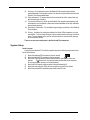
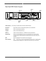
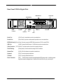
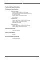
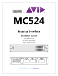
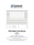
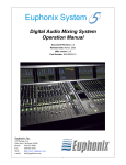
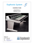
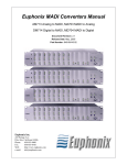
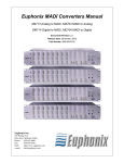
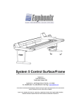
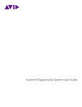
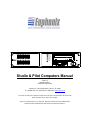
STUDIO COMPUTER
POWER GOOD
DISK ACCESS
SCSI BUSY
LAN 1 ACTIVE
LAN 2 ACTIVE
RS-422 DATA
RS-422 DATA
RESET
Studio & Pilot Computers Manual
Version 1.0
Part# 840-07590-01
Publish date: August 1999
Euphonix Inc. 220 Portage Avenue Palo Alto , CA 94306
Tel: (650)855-0400 Fax: (650) 855-0410 Web Page: www.euphonix.com
In the interest of continued product development, Euphonix reserves the right to make improvements in this manual and the
product it describes at any time, without notice or obligation.
System 5, S-5, PatchNet, eMix, EuCon, R-1, Studio Hub, , Digital Studio Controller, DSC, CleaR, GainBall, SnapShot,
SnapShot Automation, SnapShot Recall and Total Automation are trademarks of Euphonix Inc.
SC
261
This page intentionally left blank
Studio & Pilot Computers Manual
Page 2
Version 1.01 ©1999 Euphonix Inc.
TABLE OF CONTENTS
Box Inventory...........................................................................................................................4
Safety and Precautions .........................................................................................................4
System Setup.............................................................................................................................5
Power On Sequence ..................................................................................................................6
Power Down Sequence ..............................................................................................................6
CE................................................................................................................................................7
Component Overview ............................................................................................................8
Functional Description...............................................................................................................8
Features.....................................................................................................................................8
Typical Use ................................................................................................................................8
Physical Specifications .........................................................................................................9
Front Panel ................................................................................................................................9
Front Panel Features..................................................................................................................9
Dimensions and Weight ........................................................................................................... 10
Rear Panel SC261 Studio Computer......................................................................................... 11
Rear Panel PC253d Digital Pilot ............................................................................................... 12
Rear PanelPC253I Interface Pilot ............................................................................................. 13
Technical Specifications.....................................................................................................14
Performance Specifications..................................................................................................... 14
Power Requirements................................................................................................................ 14
Power Consumption................................................................................................................. 14
Environmental Requirements................................................................................................... 14
Studio & Pilot Computers Manual
Page 3
Version 1.01 ©1999 Euphonix Inc.
Box Inventory
The SC261 System Computer is packaged as follows:
Description
SC261 System PC Package
SC261 package
Pilot Computers manual
Part #
956-06668-01
936-07369-01
840-07590-01
Qty
1
1
1
The PC253d Digital Pilot is packaged as follows:
Description
PC253d Digital Pilot Package
PC253d package
Pilot Computers manual
Part #
956-06647-01
936-07370-01
840-07590-01
Qty
1
1
1
The PC253i Interface Pilot is packaged as follows:
Description
PC253i Interface Pilot Package
PC253i package
Pilot Computers manual
Part #
956-06646-01
936-07371-01
840-07590-01
Qty
1
1
1
Safety and Precautions
1) Read Instructions - Read all the safety and operation instructions before operating the
Studio & Pilot computers.
2) Heed Warnings – Follow all warnings on the Studio & Pilot computers and in these
operating instructions.
3) Water and Moisture – Do not use the Studio & Pilot computers near water.
4) Heat – Locate the Studio & Pilot computers away from heat sources.
5) Power Sources – Connect the Studio & Pilot computers only to a power supply of the
type described in these operation instructions or as marked on the Studio & Pilot
computers.
6) Power Cord Protection – Route power cords so that they are not likely to be walked
upon or pinched by items placed on them.
7) Object and Liquid Entry – Do not drop objects or spill liquids on the Studio & Pilot
computers.
8) Damage Requiring Service – The Studio & Pilot computers should be serviced only by
qualified personnel when:
a) Objects have fallen, or liquid has spilled into the Studio & Pilot computers; or
b) The Studio & Pilot computers do not appear to operate or exhibit a marked
change in performance; or,
c) The Studio & Pilot computers have been dropped or there is damage to a
chassis.
Studio & Pilot Computers Manual
Page 4
Version 1.01 ©1999 Euphonix Inc.
9)
10)
11)
12)
13)
Servicing – Do not attempt to service the Studio & Pilot computers beyond those
means described in this operation manual. All other servicing should be referred to the
Euphonix Tech Support department.
Fuse replacement – To prevent electric shock and avoid risk of fire, replace fuse only
with the same type and rating.
To prevent electric shock, do not use the Studio & Pilot computers polarized plug with
and extension cord, receptacle or other outlet unless the blades can be fully inserted to
prevent blade exposure.
Grounding or Polarization – Do not defeat the grounding or polarization of the Studio &
Pilot computers.
Cooling - Ventilation for cooling is provided to the Studio & Pilot computers via a rear
mounted fan. This fan draws cooling air into the chassis from the openings on the front
panel. To avoid damage to the units, do not block the fan or the front panel openings.
Do not disconnect the fan.
There are no user serviceable parts in the Studio and Pilot computers.
System Setup
Studio Computer
Configured as a standard PC, the Studio computer requires the following connections to the
rear of the enclosure:
1) Attach the keyboard PS2 connector to the port marked
.
2) Attach the trackball PS2 connector to the port marked .
3) Attach the 15 pin high density Dsub connector from the video monitor to the port
marked
. This connector is on a separate video card installed on the computer.
Do not use the video connector on the motherboard.
4) Attach the RJ45 network cable connector to the port labeled LAN1.
5) Attach the other end of the RJ45 cable to an input port on the EuCon Switch.
6) Attach the provided IEC compatible power cable to the IEC inlet.
Studio & Pilot Computers Manual
Page 5
Version 1.01 ©1999 Euphonix Inc.
Digital Pilot
1)
2)
3)
Attach the RJ45 network cable connector to the port labeled LAN1.
Attach the IEEE1394 cable to one of the ports marked IEEE1394. Attach the other end
of this cable to the FC631 card at one of the ports labeled FIREWIRE on the
corresponding DF64 Digital Frame.
Attach the provided IEC compatible power cable to the IEC inlet.
Interface Pilot
1)
2)
3)
4)
5)
6)
Attach the RJ45 network cable connector to the port labeled LAN1.
Attach the TCC breakout cable to the DB62 connector on the TCC card lower
connector). This breaks out to 4-DB15 control lines.
Attach a 15 pin Dsub cable from control line #1 to the MC524 Monitor Interface.
Attach additional 15 pin Dsub cables from control lines 2, 3, and 4 to ML530 Mic-Line
Interfaces.
If more than 3 ML530s need to be connected, attach another TCC breakout cable to
the extension DB62 connector (upper) and connect DB15 cables the ML530 Mic-Line
Interfaces from control lines 5, 6, 7, and 8.
Attach a parallel port cable between the parallel ports on the Interface Pilot and the
MIDI interface.
Power On Sequence
1)
The Studio Computer is powered on first when bringing up System 5.
2)
Power on the Studio Hub, MIDI Express, TT007, Eucon Hub, and all converters.
3)
Bring up the eMix software and power on the console, and the Interface Pilot and
Digital Pilot(s).
4)
When the Digital Pilots indicate that their virtual mixers are loaded, the DF64 Digital
Frames can be powered on.
Power Down Sequence
Please use the following steps to power down the Studio Computer:
1) Shut down all applications. Press CTRL+ALT+* together to exit eMix.
2) From the Windows desktop, guide the mouse cursor into the lower left hand corner of
the monitor screen, the Start Bar will appear.
3) Left-click on the Start button on the lower left of the Start Bar. A menu will appear.
4) Left-click on the lowest item in the menu; Shut Down. A menu will appear.
5) Click on Shut Down. Click on OK.
6) Wait until you are presented with a screen that states, It is now safe to shut down the
computer.
7) Press the power button on the front of the Studio PC.
Studio & Pilot Computers Manual
Page 6
Version 1.01 ©1999 Euphonix Inc.
CE
The Studio & Pilot computers are fully CE compliant. Documentation is available from the
factory.
Studio & Pilot Computers Manual
Page 7
Version 1.01 ©1999 Euphonix Inc.
Component Overview
Functional Description
System 5 includes three types of rack mount computers that manage communications among
several of the System 5 sub components. The three types are designated Studio Computer
(SC261), Digital Pilot (PC253i), and Interface Pilot (PC253d). Each type has a specific configuration
and function within System 5. All are interconnected on a 100T full duplex network via the EuCon
Network and Hub.
SC261 Studio Computer
The Studio Computer runs the eMix software on a NT platform and is equipped with a mouse,
keyboard, and video monitor. Use this computer station for non real time audio functions such as
setting system configuration parameters, patching signal paths, file management, and backups.
System configuration information is communicated to other System 5 components via the EuCon
network.
PC253d Digital Pilot
The Digital Pilot(s) receive control information from the individual System 5 Control Modules.
This information is then used to manipulate the digital audio which passes through the DF64 Digital
Frame(s). Control Module signals are passed to the Digital Pilot(s) via the EuCon Hub over a RJ45
network cable. The Digital Pilot translates the incoming Ethernet signal into high speed IEEE1394
protocol which is used to control audio parameters in the DF64. One Digital Pilot is required for
each DF64 Digital Frame.
PC253i Interface Pilot
The Interface Pilot manages communications between the System 5 Control Surface Modules
and the Monitor Interface, Mic-Line Interface, MIDI Interface, and TT-007 Machine Control module.
Control Module signals are passed to the Interface Pilot via the EuCon Hub over a RJ45 network
cable. The Interface Pilot controls parameters in the Monitor Interface, Mic-Line Interface, MIDI
Interface, and TT-007.
Features
The Studio Computer, Digital Pilot , and Interface Pilot are high speed Pentium II computers in a
2 RU brushed aluminum cases.
Typical Use
The Studio & Pilot computers ARE NOT PROVIDED AS A GENERAL COMPUTER TOOLS. Do
not run third party software on any of the System 5 computers (unless specified or included by
Euphonix). Euphonix does not guarantee correct and reliable operation of System 5 under such
circumstances.
Studio & Pilot Computers Manual
Page 8
Version 1.01 ©1999 Euphonix Inc.
Physical Specifications
Front Panel
STUDIO COMPUTER
POWER GOOD
DISK ACCESS
SCSI BUSY
LAN 1 ACTIVE
LAN 2 ACTIVE
RS-422 DATA
RS-422 DATA
SC
RESET
261
DIGITAL PILOT COMPUTER
POWER GOOD
PC
253d
RESET
INTERFACE PILOT COMPUTER
PC
253i
RESET
Front Panel Features
Power Switch
On/Off button powers up the unit.
24X CD ROM Drive(SC261) For upgrading system software.
3.5” Floppy Drive
For upgrading system software, back up of Title files, or other system housekeeping
duties.
Power Good LED (SC261 and PC253d) Indicates the unit is powered up.
Disk Access LED (SC261) Indicates the Operating System (DOS) drive is active.
SCSI Busy LED
(SC261) Indicates the SCSI network is active.
LAN 1 Active LED (SC261) Indicates activity on the first SCSI port.
LAN 2 Active LED (SC261) Indicates activity on the second SCSI port.
RS-422 Data LED (SC261) Indicates activity on the first RS-422 serial port.
Studio & Pilot Computers Manual
Page 9
Version 1.01 ©1999 Euphonix Inc.
RS-422 Data LED (SC261) Indicates activity on the second RS-422 serial port.
Reset Button
Can be used for a ‘warm’ reboot of computer. This button is recessed into the front panel
so it will not be accidentally pressed.
Dimensions and Weight
Height:
Width:
Depth:
Weight:
Studio & Pilot Computers Manual
3.5 inches
19 inches
18 inches
25 lbs
Page 10
Version 1.01 ©1999 Euphonix Inc.
Rear Panel SC261 Studio Computer
Network
Port
SCSI – Not
used
Parallel
Port
L
A
N
2
SC261
L
A
N
3
PARALLEL
|O|O|
|O|O|
Power
Connector
Do not use
USB Port
Unused
Network
Port
Keyboard
Trackball
Video
Serial Ports
Video Connector (15 Pin D sub) The video monitor connection is made at this port.
Parallel Port
(25 pin Dsub) A printer or other parallel port device can connected here.
Keyboard
(PS2) Connect keyboard cable here.
Trackball
(PS2) Connect trackball cable here.
USB Port
(USB) Universal serial Bus port. A USB device can be connected here.
Network Ports
(RJ45) A Local Area Network (LAN) can be connected at this port to give the Studio
computer access to networked resources including Internet access if your facility is so
equipped.
SCSI
(68 pin D-sub female) This connection is not currently used.
Power Connector
(IEC) The IEC power connector accepts standard IEC power cords. A switching power
supplied is used so voltages from 110volts to 240 volts, 50 or 60 cycle, can be input.
Studio & Pilot Computers Manual
Page 11
Version 1.01 ©1999 Euphonix Inc.
Rear Panel PC253d Digital Pilot
IEEE1394 Ports
Parallel Port
Pilot ID Setting
PARALLEL
SC253d
SERIAL 1
SERIAL 2
PILOT ID
PS2 MOUSE
USB
VGA
PS2 KEYBOARD
Power
Connector
Trackball
Keyboard
Network
Port
USB Port
Serial Port
Video
Serial Port
(9 Pin D sub) A serial device can be connected here.
Parallel Port
(25 pin Dsub) A printer or other parallel port device can connected here.
IEEE1394 Ports(3) (62 pin Dsub) Connect one port to IEEE1394 connector on FC631 card in DF64.
USB Port
(USB) Universal Serial Bus port. A USB device can be connected here.
Video Connector (15 Pin D sub) The video monitor connection is made at this port.
Pilot ID Setting
(Rotary switch) Use this switch to assign Pilot ID numbers.
Network Port
(RJ45) A EuCon Network connection is made here..
Keyboard
(PS2) Connect keyboard cable here.
Trackball
(PS2) Connect trackball cable here.
Power Connector
(IEC) The IEC power connector accepts standard IEC power cords. A switching power
supplied is used so voltages from 110volts to 240 volts, 50 or 60 cycle, can be input.
Studio & Pilot Computers Manual
Page 12
Version 1.01 ©1999 Euphonix Inc.
Rear PanelPC253I Interface Pilot
TCC Main Port
Parallel Port
TCC Extension
Port
Pilot ID Setting
PARALLEL
SC253i
SERIAL 1
SERIAL 2
PILOT ID
PS2 MOUSE
USB
VGA
PS2 KEYBOARD
Power
Connector
Trackball
Keyboard
Network
Port
USB Port
Serial Port
Video
Serial Port
(9 Pin D sub) A serial device can be connected here.
Parallel Port
(25 pin Dsub) A printer or other parallel port device can connected here.
TCC Main Port
(62 pin Dsub) Connect TTC breakout cable here.
TCC Extension Port
(62 pin Dsub) Connect second TTC breakout cable here if more than 3 Mic-Line
interfaces are used..
USB Port
(USB) Universal Serial Bus port. A USB device can be connected here.
Video Connector (15 Pin D sub) The video monitor connection is made at this port.
Pilot ID Setting
(Rotary switch) Use this switch to assign Pilot ID numbers.
Network Port
(RJ45) A EuCon Network connection is made here..
Keyboard
(PS2) Connect keyboard cable here.
Trackball
(PS2) Connect trackball cable here.
Power Connector
(IEC) The IEC power connector accepts standard IEC power cords. A switching power
supplied is used so voltages from 110volts to 240 volts, 50 or 60 cycle, can be input.
Studio & Pilot Computers Manual
Page 13
Version 1.01 ©1999 Euphonix Inc.
Technical Specifications
Performance Specifications
SC261 Studio Computer
Pentium II, 350 MHz, 256 MB RAM, 6 GB HD storage
3D/2D accelerated graphics at 1024 X 768 pixels with 16-bit color
Ultra wide SCSI controller
10Base-T/100Base-T Ethernet network controller
USB 1.0 interface
PC253d Digital Pilot
Tillamook – MMX 266 MHz, 128 MB RAM, 8 GB HD storage
10Base-T/100Base-T Ethernet network controller
400 Mbit IEEE 1394 interface
PC253i Interface Pilot
Tillamook – MMX 266 MHz, 128 MB RAM, 8 GB HD storage
10Base-T/100Base-T Ethernet network controller
Power Requirements
110-240 VAC at 50/60 Hz
Power Consumption
200 Watts
Environmental Requirements
5 to 35 degree Centigrade
Studio & Pilot Computers Manual
Page 14
Version 1.01 ©1999 Euphonix Inc.