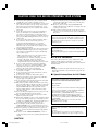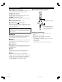
1
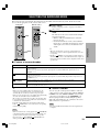
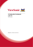
UB
HOME THEATER SOUND SYSTEM
TSS-10
INPUT
DIGITAL 1
DIGITAL 2
ANALOG
MODE
DTS
DIGITAL
PL
MOVIE
PL
MUSIC
VOLUME TRIM
7
+6
6
+4
5
+2
INPUT
4
0
3
–2
MODE
2
–4
1
–6
REAR
S.WOOFER
VOLUME
MUTE
TEST
Active Servo
Technology
SILENT
STANDBY/ON
TSS-10
HOME THEATER SOUND SYSTEM
OWNER’S MANUAL
TSS-10(H1)(UB)a
1
02.7.31, 2:34 PM
CAUTION: READ THIS BEFORE OPERATING YOUR SYSTEM.
1
2
3
4
5
6
7
8
9
10
11
12
13
14
15
16
17
18
To assure the finest performance, please read this manual
carefully. Keep it in a safe place for future reference.
Install this sound system in a well ventilated, cool, dry, clean
place with at least 20 cm on the top, 10 cm on the left and
right, and 10 cm at the back of the amplifier unit — away
from direct sunlight, heat sources, vibration, dust, moisture,
and/or cold.
Locate this system away from other electrical appliances,
motors, or transformers to avoid humming sounds. To
prevent fire or electrical shock, do not place this system
where it may get exposed to dripping or splashing, and never
put any objects filled with liquids, such as vases, on the top
of the system.
Do not expose this system to sudden temperature changes
from cold to hot, and do not locate this system in a
environment with high humidity (i.e. a room with a
humidifier) to prevent condensation inside this system,
which may cause an electrical shock, fire, damage to this
system, and/or personal injury.
Avoid installing this system in a place where foreign objects
and liquid might fall. It might cause a fire, damage to this
system and/or personal injury. Do not place the following
objects on this system:
– Other components, as they may cause damage and/or
discoloration on the surface of this system.
– Burning objects (i.e. candles), as they may cause fire,
damage to this system, and/or personal injury.
– Containers with liquid in them, as they may cause
electrical shock to the user and/or damage to this system.
Do not cover this system with a newspaper, tablecloth,
curtain, etc. in order not to obstruct heat radiation. If the
temperature inside this system rises, it may cause fire,
damage to this system, and/or personal injury.
Do not plug in this system to a wall outlet until all
connections are complete.
Do not operate this system upside-down. It may overheat,
possibly causing damage.
Do not use force on switches, knobs and/or cables.
When disconnecting the power cable from the wall outlet,
grasp the plug; do not pull the cable.
Do not clean this system with chemical solvents; this might
damage the finish. Use a clean, dry cloth.
Only voltage specified on this system must be used. Using
this system with a higher voltage than specified is dangerous
and may cause fire, damage to this system, and/or personal
injury. YAMAHA will not be held responsible for any
damage resulting from use of this system with a voltage
other than specified.
To prevent damage by lightning, disconnect the power cable
from the wall outlet during an electrical storm.
Take care of this system so that no foreign objects and/or
liquid drops inside this system.
When using a humidifier, be sure to avoid condensation inside
this system by allowing enough spaces around this system or
avoiding excess humidification. Condensation might cause a
fire, damage to this system, and/or electric shock.
Do not attempt to modify or fix this system. Contact
qualified YAMAHA service personnel when any service is
needed. The cabinet should never be opened for any reasons.
When not planning to use this system for long periods of
time (i.e. vacation), disconnect the AC power plug from the
wall outlet.
Be sure to read the “TROUBLESHOOTING” section on
common operating errors before concluding that this system
is faulty.
19 Before moving this system, press STANDBY/ON to set this
system in the standby mode, and disconnect the AC power
plug from the wall outlet.
20 Be sure to only use the AC adaptor (LSE9802B1540)
included with this system. Otherwise, you might cause a fire
or damage to this system.
21 This system is designed for home use only. Never use this
system in a car, etc., otherwise it may cause a malfunction of
this system.
This system is not disconnected from the AC power source as
long as it is connected to the wall outlet, even if this system
itself is turned off. This state is called the standby mode. In
this state, this system is designed to consume a very small
quantity of power.
FOR CANADIAN CUSTOMERS
To prevent electric shock, match wide blade of plug to wide
slot and fully insert.
This Class B digital apparatus complies with Canadian ICES003.
■ For U.K. customers
If the socket outlets in the home are not suitable for the plug
supplied with this appliance, it should be cut off and an
appropriate 3 pin plug fitted. For details, refer to the instructions
described below.
Note
• The plug severed from the mains lead must be destroyed, as a
plug with bared flexible cord is hazardous if engaged in a live
socket outlet.
■ Special Instructions for U.K. Model
IMPORTANT
THE WIRES IN MAINS LEAD ARE COLOURED IN
ACCORDANCE WITH THE FOLLOWING CODE:
Blue: NEUTRAL
Brown: LIVE
As the colours of the wires in the mains lead of this apparatus
may not correspond with the coloured markings identifying
the terminals in your plug, proceed as follows:
The wire which is coloured BLUE must be connected to the
terminal which is marked with the letter N or coloured
BLACK. The wire which is coloured BROWN must be
connected to the terminal which is marked with the letter L or
coloured RED.
Making sure that neither core is connected to the earth
terminal of the three pin plug.
IMPORTANT
Please record the serial number of this system in the space below.
MODEL:
Serial No.:
The serial number is located on the rear of the amplifier unit.
Retain this Owner’s Manual in a safe place for future reference.
CAUTION
TSS-10Eng_Cau(GB)-b
2
02.7.31, 2:34 PM
PREPARATION
FEATURES
● Home Theater Sound
● Includes Dolby Digital, Dolby Pro
Logic II and DTS Decoders
This system can reproduce the sound field of the
software with the
,
or
logo mark, and also reproduce normal 2-channel
stereo sources in surround sound.
PREPARATION
FEATURES .......................................................................... 1
CHECKING THE ACCESSORIES ................................... 2
INSTALLING BATTERIES IN THE REMOTE
CONTROL ........................................................................... 2
CONTROLS AND FUNCTIONS ....................................... 3
SETTING UP THE SYSTEM ............................................ 5
CONNECTIONS .................................................................. 7
Connecting audio components .......................................... 8
Connecting the speakers .................................................... 9
Connecting the power cable ............................................ 10
ADJUSTING SPEAKER OUTPUT LEVELS ................ 11
PREPARATION
This system delivers a realistic and powerful
sound experience like that found in a movie
theater.
CONTENTS
● Virtual Surround (by using
headphones) (SILENT CINEMA)
OPERATION
PLAYING A SOURCE ...................................................... 12
SELECTING THE SURROUND MODE ........................ 13
TROUBLESHOOTING .................................................... 14
GLOSSARY ....................................................................... 16
SPECIFICATIONS ............................................................ 17
APPENDIX
APPENDIX
OPERATION
This system also enables you to enjoy a virtual
surround sound by using headphones.
■ About this manual
Manufactured under license from
Dolby Laboratories.
“Dolby”, “Pro Logic”, and the
double-D symbol are trademarks of
Dolby Laboratories.
“DTS” and “DTS Digital
Surround” are registered
trademarks of Digital Theater
Systems, Inc.
English
• y indicates a tip for your operation.
• Some operations can be performed by using the buttons
on either the main unit or the remote control. In this
case, the operations performed by using the remote
control are described in this manual.
• This manual is printed prior to production. Design and
specifications are subject to change in part for the
reason of the improvement in operativity ability, and
others. In this case, the product has priority.
• Some of the illustrations and names of the package
contents etc. written in this manual may differ from the
actual products and the names written on the package
etc.
1
TSS-10Eng(UB)a
1
02.7.31, 2:34 PM
CHECKING THE ACCESSORIES
Check your package to make sure it contains the following items.
Remote control
Power cable
Batteries
(AAA, R03, UM-4)
Fastener (1 set)
(for the center speaker)
Non-skid pads
(3 sets: 24 pieces)
INPUT
MODE
REAR
S.WOOFER
VOLUME
MUTE
AC adaptor
(LSE9802B1540)
TEST
3.5 mm stereo mini/
RCA stereo pin cable
Optical cable
Stand
(for the amplifier unit)
Screws
(2 pieces)
Audio pin cable
INSTALLING BATTERIES IN THE REMOTE CONTROL
Insert the batteries in the correct direction by aligning the
+ and – marks on the batteries with the polarity markings
(+ and –) inside the battery compartment.
2
1
■ Notes on batteries
• Change all of the batteries if you notice a decrease in
the operating range of the remote control.
• Do not use old batteries together with new ones.
• Do not use different types of batteries (such as alkaline
and manganese batteries) together. Read the packaging
carefully as these different types of batteries may have
the same shape and color.
• If the batteries have leaked, dispose of them
immediately. Avoid touching the leaked material or
letting it come into contact with clothing, etc. Clean the
battery compartment thoroughly before installing new
batteries.
3
1
Press the
part and slide off the
battery compartment cover.
2
Insert the two batteries (AAA, R03, UM-4
type) with + and – oriented properly.
The batteries can be set only from the direction
shown in the figure.
3
Slide the cover back on so that it snaps into
place.
2
TSS-10Eng(UB)a
2
02.7.31, 2:34 PM
CONTROLS AND FUNCTIONS
Remote control
Front panel
INPUT
DIGITAL 1
1
DIGITAL 2
ANALOG
2
MODE
7
DTS
DIGITAL
PL
2
MOVIE
PL
MUSIC
8
PREPARATION
1
5
INPUT
MODE
REAR
S.WOOFER
VOLUME TRIM
VOLUME
7
3
+6
6
+4
5
+2
4
0
9
3
–2
2
MUTE
TEST
–4
0
1
–6
3
4
STANDBY/ON
SILENT
6 5
1 INPUT and indicators
2 MODE (k/n) and indicators
Press this button repeatedly to select an input source
between DIGITAL 1, DIGITAL 2 and ANALOG. The
current mode is shown by the lighting of the
corresponding indicator.
Press this button (or k/n) repeatedly to select the desired
surround mode among DTS,
DIGITAL,
PLII
MOVIE,
PLII MUSIC and “off”. The current mode is
shown by the lighting of the corresponding indicator.
DIGITAL 1:
* If a DTS or Dolby Digital encoded signal is inputted when
DTS or
DIGITAL mode is not selected, the
corresponding indicator lights up dimly.
Select this to reproduce source signals received at the
DIGITAL INPUTS OPTICAL 1 terminal on the rear
panel.
Refer to page 13 for details on each surround modes.
DIGITAL 2:
Select this to reproduce source signals received at the
DIGITAL INPUTS OPTICAL 2 terminal on the rear
panel.
ANALOG:
English
Select this to reproduce source signals received at the
ANALOG INPUTS terminals on the rear panel.
3
TSS-10Eng(UB)a
3
02.7.31, 2:35 PM
CONTROLS AND FUNCTIONS
3 VOLUME (+/–) and indicators
Used for adjusting the overall volume level of this system.
The current level is shown by the lighting of the
indicators on the front panel.
VOLUME on the front panel:
Turn this control clockwise to increase the level, and
counterclockwise to decrease the level.
VOLUME +/– on the remote control:
Press + to increase the level, and – to decrease the level.
■ Using the remote control
SILENT
4 Remote control sensor
Receives signals from the remote control.
5 STANDBY/ON (
) and indicator
Each press of this button changes the status of this system
between standby mode and power on. When the power is
on, the indicator lights up.
Approximately 6 m (20 feet)
30°
30°
* The STANDBY/ON indicator
flashes while the amplifier
unit is receiving signals from
the remote control.
Standby mode
In this mode, this system will consume a small amount
of power in order to receive infrared-signals from the
remote control.
6
SILENT
Stereo headphones can be connected to this mini-jack for
private listening. Sound output from the speakers is cut
off when headphones are connected to this jack.
7 REAR +/–
These buttons are used for adjusting the sound level from
the rear speakers. Press + to increase the level, and – to
decrease the level.
Handling the remote control
• Do not spill water or other liquids on the remote
control.
• Do not drop the remote control.
• Do not leave or store the remote control in the
following types of conditions:
– high humidity or temperature such as near a heater,
stove or bath;
– dusty places; or
– in places subject to extremely low temperatures.
8 S.WOOFER +/–
These buttons are used for adjusting the sound level from
the subwoofer. Press + to increase the level, and – to
decrease the level.
9 MUTE
Press this button to cut off sound output temporarily.
Press this button again to restore sound output.
0 TEST
Press this button to reproduce a test tone from the
speakers. A test tone is reproduced from each speaker in
turn. The test tone is used for adjusting volume balance
among all the speakers. The adjustment is made by
pressing VOLUME +/– on the remote control.
4
TSS-10Eng(UB)a
4
02.7.31, 2:35 PM
SETTING UP THE SYSTEM
Recommended speaker placement
This system includes an amplifier unit, five speakers and
a subwoofer.
Before making connections, place all speakers in their
respective positions. The positioning of the speakers is
important because it controls the overall sound quality of
this system.
Place the speakers depending on your listening position
by following the instructions below.
Amplifier unit x 1
Speaker x 5
Subwoofer x 1
* The front/center/rear speakers can be mounted on a wall. (See
the next page.)
The three speakers with a 3 m cable are used as front
speakers and a center speaker.
The two speakers with a 10 m cable are used as rear
speakers.
Front speakers: On both sides of and at approximately
the same height as the TV.
The role of respective speakers
Center speaker: Precisely between the front speakers.
The front speakers are used for reproducing main channel
sound. The rear speakers are used for effect sounds, and
the center speaker is for center channel sound (dialog
etc.).
The subwoofer is used for reproducing sounds of low
frequencies from the front, center and rear surround
channels. The subwoofer also reproduces sounds of the
subwoofer channel when a DTS or Dolby Digital encoded
source is played.
PREPARATION
System configuration
Rear speakers: Behind your listening position or on
both sides of the listening room.
* The center speaker can be mounted
on the monitor as shown on the next
page.
Subwoofer:
On the floor. The position of the
subwoofer is not so critical because
low bass tones are not highly
directional.
Note
• Although the speaker system in this system is magnetically
shielded, it may still affect the color on the television monitor
when using this system near the television. Adjust the relative
positions of this system and the television if this happens.
Right front
speaker
Center
speaker
Subwoofer
Amplifier
unit
Right rear
speaker
Left front
speaker
English
Left rear
speaker
5
TSS-10Eng(UB)a
5
02.7.31, 2:35 PM
SETTING UP THE SYSTEM
䡵 Adjusting the front angle of the front/
center/rear speakers
䡵 Placing a center speaker on top of the
monitor
The front angle of the speakers can be adjusted as shown
below.
Loosen the screw on the bottom of the speaker stand.
When placing the center speaker on top of the monitor,
remove the stand from the speaker, and attach the
provided fastener at the bottom of the speaker and on top
of the monitor to prevent the speaker from falling.
* Attach the supplied non-skid pads at the four corners on
the bottom of the stand for improved stability.
* Do not place the speaker on top of the monitor with an
inclination of more than 10 degrees.
1
Non-skid
pads
2
10ⴗ
10ⴗ
Fastener
Adjust the speaker angle on the stand as you prefer,
and then tighten the screw.
Note
• Though this speaker is a magnetically shielded type, there may
be some influence on the monitor picture depending on the
type of monitor or the placement of the speaker. In such a case,
place the speaker further apart from the monitor until there is
no influence on the monitor picture.
䡵 Mounting the front/center/rear speakers
on a wall
The speakers can also be hung on the wall.
Remove the stand from the speaker. Fasten screws into a
firm wall or wall support as shown in the figure, and hang
the slits on the rear of the speaker on the protruding
screws.
* Make sure that the screws are securely caught by the slits.
Tapping screw (Diam. 4 mm)
(Available in hardware stores)
䡵 Mounting the amplifier unit on the
supplied stand
For improved stability, it is recommended to mount the
amplifier unit on the supplied stand with the supplied
screws as shown below.
* Attach the supplied non-skid pads at the four corners on the
bottom of the stand for improved stability.
Non-skid
pads
5 mm
Min.
20 mm
Wall/ wall
support
50 mm
Warning
• Each speaker weighs 0.4 kg (0.9 lbs.). Do not mount them on
thin plywood or a wall with soft surface material. If mounted,
the screws may come out of the flimsy surface and the speakers
may fall. This could damage the speakers and cause personal
injury.
• Do not install the speakers on a wall with nails, adhesives, or
any other unstable hardware. Long-term use and vibrations
may cause them to fall.
• To avoid accidents resulting from tripping over loose speaker
cables, fix them to the wall.
6
TSS-10Eng(UB)a
6
02.8.1, 10:08 PM
CONNECTIONS
CAUTION
Always be sure to turn off the amplifier unit and any component to be connected when making connections.
PREPARATION
To ensure proper connections
• Connect the white plug of the connection cable to the left “L” (white) audio signal terminal and connect the red plug
to the right “R” (red) terminal.
• Insert the plug securely. If the plug is not inserted securely, noise may result or sound may not be output.
• Since the method of connection and terminal names differ depending on the component being used, be sure to refer
to the instruction manuals for all components being connected.
• After connections have been made, check one more time that wiring has been made properly.
DVD player
VCR
Personal computer
Video game player
TV/digital TV/cable TV
INPUT
DIGITAL 1
DIGITAL 2
ANALOG
Amplifier unit
MODE
DTS
DIGITAL
PL
MOVIE
PL
MUSIC
VOLUME TRIM
7
+6
6
+4
5
+2
4
0
* This system cannot be connected to video signal input/
output terminals of a TV, VCR, DVD player, etc.
3
–2
To AC outlet
2
AC adaptor
–4
1
–6
Active Servo
Technology
SILENT
STANDBY/ON
TSS-10
HOME THEATER SOUND SYSTEM
Left rear
speaker
Right rear
speaker
Right front
speaker
English
Center
speaker
Left front
speaker
Subwoofer
7
TSS-10Eng(UB)a
7
02.7.31, 2:35 PM
CONNECTIONS
Connecting audio components
• For connections, use the included or commercially available connection cables suitable for respective connections.
Anti-dust cap
Anti-dust cap
Rear panel
Remove the cap covering the
DIGITAL INPUTS OPTICAL
terminal when connecting an
optical cable. Safely store the
cap and always re-insert it in
the terminal when the terminal
is not in use. (This cap
prevents the entrance of dust.)
SPEAKER
OUTPUTS
FRONT
L
Optical cable
R
OPTICAL
DIGITAL
OUTPUT
REAR
(SURROUND)
L
DVD player, video
game player, etc.
R
DIGITAL
INPUTS
OPTICAL
CENTER
OPTICAL
DIGITAL
OUTPUT
1
TV/digital TV/cable
TV, etc.
2
Optical cable
S. WOOFER
L
L
R
R
INPUT
Audio pin cable
OUTPUT
DIGITAL 1
DIGITAL 2
VCR, etc.
ANALOG
ANALOG
INPUTS
MODE
DTS
DIGITAL
PL
MOVIE
PL
DC IN 15V
MUSIC
VOLUME TRIM
7
+6
6
+4
5
+2
4
OUTPUT
0
3
–2
2
–4
1
3.5 mm stereo
mini/RCA stereo
pin cable
–6
SILENT
Personal computer,
etc.
STANDBY/ON
Amplifier unit
• Connect the optical digital output terminal on the DVD player, etc. to the DIGITAL INPUTS OPTICAL 1 (optical)
digital input terminal on the amplifier unit using an optical cable. In the same way, connect the optical digital output
terminal on the satellite tuner, etc. to the DIGITAL INPUTS OPTICAL 2 (optical) digital input terminal on the
amplifier unit using an optical cable. These connections bring you digital sound.
• When connecting a VCR, etc. without a digital output terminal, connect the audio output terminals to the ANALOG
INPUTS audio input terminals on the amplifier unit using the audio pin cable.
• When connecting a personal computer, etc. which has a 3.5 mm-stereo mini jack only for audio output, connect it to
the ANALOG INPUTS audio input terminals on the amplifier unit using the 3.5 mm stereo mini/RCA stereo pin
cable.
Note
• The amplifier unit has no video input terminal. To enjoy watching a source played on the DVD player etc. connected
to the amplifier unit, connect the video output of DVD player to the TV.
y
• The TSS-10 cannot record any audio or video source.
8
TSS-10Eng(UB)a
8
02.7.31, 2:35 PM
CONNECTIONS
Connecting the speakers
Connect the speakers to the amplifier unit.
Connect the three speakers with a 3 m cable to the FRONT L, R and CENTER terminals. Connect the two speakers with
a 10 m cable to the REAR L and R terminals. Connect the subwoofer to the SUBWOOFER terminal.
PREPARATION
Note
• Do not connect any speakers to the speaker terminals on the amplifier unit except for the supplied speakers.
Rear panel
Left front
speaker
Right front
speaker
SPEAKER
OUTPUTS
FRONT
L
R
Left rear
speaker
Right rear
speaker
REAR
(SURROUND)
L
Center
speaker
R
DIGITAL
INPUTS
OPTICAL
CENTER
1
2
S. WOOFER
L
R
INPUT
DIGITAL 1
DIGITAL 2
ANALOG
ANALOG
INPUTS
MODE
DTS
DIGITAL
PL
DC IN 15V
MOVIE
PL
MUSIC
VOLUME TRIM
7
+6
6
+4
5
+2
4
0
3
–2
2
–4
1
–6
Subwoofer
SILENT
STANDBY/ON
Amplifier unit
CAUTIONS
English
• The SPEAKER OUTPUTS terminals on the rear of the amplifier unit are only designed for connection of the
supplied speakers. Never connect these terminals to an AV amplifier or a power amplifier, as it may cause
misoperation, fire and/or damage to this system.
• Secure the speaker cables so that they will not catch on hands or feet.
9
TSS-10Eng(UB)a
9
02.7.31, 2:35 PM
CONNECTIONS
Connecting the power cable
Rear panel
CENTER
1
Amplifier unit
2
S. WOOFER
INPUT
DIGITAL 1
Once all connections have been made, check them one
more time. Finally, plug in the amplifier unit to the wall
outlet in the following procedure.
1. Connect the included AC adaptor to the amplifier
unit.
2. Connect the included power cable to the AC adaptor.
3. Insert the plug of the power cable into the wall outlet.
DIGITAL 2
ANALOG
L
MODE
DTS
DIGITAL
PL
MOVIE
PL
R
MUSIC
VOLUME TRIM
Notes
7
+6
6
+4
ANALOG
INPUTS
5
+2
4
0
3
–2
2
DC IN 15V
–4
1
–6
SILENT
AC adaptor
(included)
Power cable
(U.S.A. model)
(included)
STANDBY/ON
• Disconnect the power cable if you will not use this system for
an extended period.
• When placing the included AC adaptor on the rack, etc., be sure
to fix the adaptor on the rack, etc. to prevent it from falling. If
the adaptor falls, it may cause personal injury or damage to the
adaptor and/or other equipment.
• Do not connect the included AC adaptor to any unit other than
the amplifier unit of this system.
To AC outlet
10
TSS-10Eng(UB)a
10
02.7.31, 2:35 PM
ADJUSTING SPEAKER OUTPUT LEVELS
Left front
Right front
PREPARATION
This section explains how to adjust speaker output levels
using the test tone generator. When this adjustment is
complete, the output level heard at the listening position
should be the same from each speaker. This is important
for best performance of the various decoders (Dolby
Digital, Dolby Pro Logic II and DTS).
Center
Note
• Since this system cannot enter the test mode while headphones
are connected to the amplifier unit, be sure to unplug the
headphones from the
SILENT jack when using the test
tone.
Right rear
Left rear
Using the test tone
3
Adjust the level of each speaker by pressing
VOLUME +/– so that it matches the level of
the front speakers.
While adjusting, the test tone is heard from the
selected speakers. After – or + is released, the test
tone begins travelling to another speaker again.
4
When adjustment is complete, press TEST to
stop the test tone.
Use the test tone to balance the output levels of the
speakers.
Notes
• The adjustment of each speaker output level should be made at
your listening position using the remote control.
• The test tone may not be heard if the volume level of this
system is too low. Confirm that the volume is set to a proper
listening level.
• While adjusting, the level of the selected speaker is shown
by the lighting of the VOLUME indicators on the front
panel. The default level is also shown by the dim lighting
of the corresponding indicator.
INPUT
MODE
REAR
y
S.WOOFER
VOLUME
VOLUME +/–
MUTE
TEST
TEST
• You can enjoy listening to the input source at the desired
volume simply by turning VOLUME on the front panel or
pressing VOLUME +/– on the remote control.
Notes
• If you press INPUT on the remote control when the test tone is
outputted, the output levels of all channels are reset to the
default levels.
• The levels of the left and right front speakers cannot be set over
the point on the VOLUME indicator shown in the figure below.
PL
MOVIE
PL
MUSIC
INPUT
DIGITAL 1
DIGITAL 2
ANALOG
VOLUME TRIM
MODE
DTS
DIGITAL
7
PL
MOVIE
PL
+6
6
MUSIC
VOLUME TRIM
+4
7
+6
6
5
1
2
+4
5
+2
Press
to turn on the power.
+2
4
0
3
4
–2
2
–4
0
1
–6
3
–2
2
–4
1
–6
SILENT
STANDBY/ON
English
Press TEST to output the test tone.
The test tone is heard (in order) from the left front,
center, right front, right rear and left rear speaker.
The tone is produced for about 2.5 seconds from
each speaker.
• All of the INPUT indicators flash while the test tone is
being outputted.
11
TSS-10Eng(UB)a
11
02.7.31, 2:35 PM
PLAYING A SOURCE
Let’s listen to sources played on the audio and video
components connected to this system.
■ To adjust the subwoofer level
While listening to a source, press
S.WOOFER – or +.
Pressing + increases and – decreases the level.
Remote control
Front panel
y
• While adjusting, the current level is shown by the lighting of
the VOLUME indicators on the front panel. The default level is
also shown by the dim lighting of the corresponding indicator.
INPUT
INPUT
DIGITAL 1
DIGITAL 2
INPUT
INPUT
MODE
ANALOG
Note
REAR
MODE
DTS
DIGITAL
PL
MOVIE
PL
S.WOOFER
REAR +/–
MUSIC
VOLUME
VOLUME TRIM
7
+6
6
+4
5
+2
4
0
3
–2
VOLUME
+/–
MUTE
MUTE
S.WOOFER
+/–
TEST
2
–4
1
–6
VOLUME
SILENT
• The adjustment cannot be made when listening with
headphones even if + or – is pressed.
■ To adjust the volume balance
between the front and rear
speakers
While listening to a source, press REAR – or
+.
Pressing + increases and – decreases the output level
of the rear speakers.
STANDBY/ON
STANDBY/ON
y
• While adjusting, the current level is shown by the lighting of
the VOLUME indicators on the front panel. The default level is
also shown by the dim lighting of the corresponding indicator.
1
Press STANDBY/ON ( ) to turn on the
power.
The STANDBY/ON indicator on the front panel
lights up.
2
Turn on the AV component connected to this
system.
3
Press INPUT repeatedly to select the input
source (DIGITAL 1, DIGITAL 2 or ANALOG).
The indicator for the selected source lights up on the
front panel.
4
Start playback on the source component.
Refer to the operation instructions for the
component.
5
Adjust the volume to the desired level.
The volume level is shown by the VOLUME
indicators on the front panel.
Control range: 0 (minimum) to 7 (maximum)
Note
• The adjustment cannot be made when listening with
headphones even if + or – is pressed.
■ To mute the sound
Press MUTE on the remote control.
To resume the audio output, press MUTE again.
y
• You can also cancel mute by pressing VOLUME +/–, INPUT,
MODE, etc.
• While being muted, the VOLUME indicators flash.
■ When you have finished using
this system
Press STANDBY/ON (
standby mode.
y
) to set this system in the
• None of the VOLUME indicators light up when the level is “0
(minimum)”.
Note
• This system can reproduce sampled digital signals (Linear
PCM, Dolby Digital, DTS) of 48 kHz or lower.
12
TSS-10Eng(UB)b
12
02.9.3, 9:15 PM
SELECTING THE SURROUND MODE
This system provides you with four surround modes for theaterlike surround sound enjoyment. For the best results,
choose a mode appropriate for the selected audio source.
Remote control
Front panel
1
Play a source.
Refer to “Playing a source” on page 12 for how to
play a source.
2
Press MODE repeatedly to select the desired
mode.
The indicator for the selected surround mode lights
up on the front panel.
• When no indicator is illuminated, no surround
mode is selected.
• Not all surround modes can be selected with all
input sources. Selectable surround modes depend
on the input source. Refer to the table below for
details.
INPUT
INPUT
DIGITAL 1
MODE
DIGITAL 2
ANALOG
REAR
MODE
MODE /
DTS
MODE
DIGITAL
PL
MOVIE
PL
S.WOOFER
MUSIC
VOLUME
VOLUME TRIM
7
+6
6
+4
5
MUTE
+2
TEST
4
0
3
–2
2
–4
1
–6
SILENT
SILENT
STANDBY/ON
• When no surround mode is selected, sound output is in 2channel stereo, and no sound is outputted from the center and
rear speakers.
• If DTS or
DIGITAL encoded signals are inputted when no
surround mode is selected, the multi-channel source signals are
mixed down into two channels and are outputted from the front
speakers only.
OPERATION
y
■ Feature of surround modes
Features
Mode
DTS
This mode precisely simulates the surround sound effects of DTS encoded sources without altering the original
sound orientation.
This mode can be selected only when the input signal is encoded with DTS and the input mode is set to
DIGITAL 1 or 2.
DIGITAL
This mode precisely simulates the surround sound effects of
DIGITAL encoded sources without altering the
original sound orientation.
This mode can be selected only when the input signal is encoded with Dolby Digital and the input mode is set
to DIGITAL 1 or 2.
PL II MOVIE
This mode enables you to enjoy 2-channel stereo sources decoded into five discrete channels.
This mode is suitable for movies, TV dramas, etc.
PL II MUSIC
This mode enables you to enjoy 2-channel stereo sources decoded into five discrete channels.
This mode is suitable for music sources.
y
• When you set the amplifier unit in the standby mode, the
current source and surround mode are memorized and are
automatically selected when you turn on the power again.
• When you select an input source, the amplifier unit automatically
selects the last surround mode used with that source.
• The acoustics of your listening room affect the surround effect.
It is recommended to use a room with fewer sound reflections
to maximize the surround effect.
• If a DTS or Dolby Digital encoded signal is inputted when
DIGITAL mode is not selected, the corresponding
DTS or
indicator lights up dimly.
■ SILENT CINEMA
You can enjoy the sound expansion similar to what you
could experience from actual speakers with the SILENT
CINEMA mode. The SILENT CINEMA can be used by
connecting your headphones to the
SILENT jack
while enjoying surround sound by using the speakers.
(When the surround mode is off, you listen to the source
with normal stereo reproduction.)
Note
• The sound of LFE channel will be mixed and output from the
headphone.
English
Notes
• When a monaural source is being played with
PL II MOVIE,
sound will be hardly heard from the front speakers and the rear
speakers. Sound can only be heard from the center speaker.
• You cannot select
PL II MOVIE/ PL II MUSIC mode
while reproducing 2-channel DTS signal.
TSS-10Eng(UB)b
13
13
02.9.3, 2:06 PM
TROUBLESHOOTING
Refer to the chart below when this system does not function properly. If the problem you are having is not listed below
or if the instruction below does not help, set this system to the standby mode, disconnect the power cable, and contact
the nearest authorized YAMAHA dealer or service center.
Problem
Cause
The amplifier unit
fails to turn on when
STANDBY/ON (
)
is pressed, or enters
in the standby mode
soon after the power
has been turned on.
The power cable is not connected or the plug
is not completely inserted.
Firmly connect the power cable.
10
The amplifier unit has been exposed to a
strong external electric shock (such as
lightning and strong static electricity).
Set the amplifier unit in the standby mode,
disconnect the power cable, plug it back in after
30 seconds, then start operating.
—
No sound.
Incorrect input cable connections.
Connect the cables properly. If the problem
persists, the cables may be defective.
8–9
An appropriate input source has not been
selected.
Select an appropriate input source with the
INPUT button.
12
The speaker connections are not secure.
Secure the connections.
9
The volume is turned down.
Turn up the volume.
12
The sound is muted.
Press MUTE or any operation buttons to cancel
a mute and adjust the volume.
12
The level of the rear speakers is set to
minimum.
Press REAR + button on the remote control to
increase the level.
—
The surround mode is off.
Select the appropriate surround mode by
pressing the MODE button.
13
No sound from the
rear speakers
Remedy
Refer
to page
No sound from the
center speaker when
the DTS or
DIGITAL mode is
selected.
The source encoded with a Dolby Digital or
DTS signal does not have a center channel
signal.
No sound from the
subwoofer.
The level of the subwoofer is set to minimum.
Press S. WOOFER + button on the remote
control to increase the level.
12
A “humming” sound
can be heard.
Incorrect cable connections to the ANALOG
INPUTS jacks.
Firmly connect the audio plugs to the
ANALOG INPUTS jacks. If the problem
persists, the cables may be defective.
8
The amplifier unit
does not operate
properly.
The internal microcomputer has been frozen
by an external electric shock (such as
lightning or excessive static electricity) or by
a power supply with low voltage.
Disconnect the power cable from the outlet and
then plug it in again after about 30 seconds.
—
There is noise
interference from
digital or highfrequency equipment,
or the amplifier unit.
The amplifier unit is too close to the digital or
high-frequency equipment.
Move the amplifier unit further away from such
equipment.
No sound from the
center and rear
speakers though the
DTS or
DIGITAL
mode indicator is
dimly illuminated.
Dim illumination of an indicator means that
signals encoded with the corresponding
format (DTS or Dolby Digital) is inputted to
this system. In this case, the signals are mixed
into 2 channels and reproduced from the front
speakers only.
Press the MODE button for the appropriate
surround format. The indicator turns bright, and
the center and rear speakers reproduce sounds
since the surround format is decoded.
—
14
TSS-10Eng(UB)a
14
02.7.31, 2:35 PM
13
TROUBLESHOOTING
Problem
Cause
Though a Dolby
Digital encoded
source is inputted to
this system and the
DIGITAL mode is
selected, no sound is
outputted from the
center and rear
speakers.
A Dolby Digital 2-channel encoded source is
inputted to this system.
If the input source is compatible with 5.1
channels, select “5.1-channel mode” on the
player which is sending signals to this system.
(If the input source is not compatible with 5.1
channels, you can enjoy the source in a multichannel mode by using the
PL II MOVIE
or MUSIC surround mode.)
13
A DTS or Dolby
Digital encoded
source cannot be
played in the DTS or
DIGITAL mode.
(Neither the DTS nor
DIGITAL mode
indicator lights up.)
The DVD player, etc. sending the playback
signal to this system is not set as follows.
• “Digital output” and “DTS or Dolby Digital
mode”
• “Output: Digital” and “Signal type: DTS or
Dolby Digital”
Make a proper setting on the DVD player, etc.
referring to the instruction manual of the player.
—
Sound is distorted.
The level of the input signal is too high.
Turn down the output level on the connected
component.
—
Noise.
The level of the input signal is too low.
Turn up the output level on the connected
component.
—
Connections are faulty or incomplete.
Make the connections again.
The amplifier unit is too close to the monitor.
Place the amplifier unit away from the monitor.
—
Wrong distance or angle.
The remote control will function within a
maximum range of 6 m (20 feet) and no more
than 30 degrees off-axis from the front panel.
4
Direct sunlight or lighting (from an inverter
type of fluorescent lamp, etc.) is striking the
remote control sensor of the amplifier unit.
Reposition the amplifier unit.
—
The batteries are weak.
Replace all batteries with new ones.
2
The remote control
does not work nor
function properly.
Remedy
Refer
to page
8–9
APPENDIX
English
15
TSS-10Eng(UB)a
15
02.7.31, 2:35 PM
GLOSSARY
■ Encode/Decode
When a signal or other information is processed,
compressed and digitized, this is called encoding.
Encoding can be used to record an extremely large
amount of information on a single CD or DVD.
An encoded signal cannot be listened to directly. It must
be returned to its original state (i.e. audible sound) and
this is called decoding.
■ DTS (Digital Theater Systems)
Digital Surround
Not all sound travels from the sound source directly into
the human ear, but instead reflects off of walls, ceilings
and other objects to arrive at the ear slightly delayed
(early reflection). It may also reflect repeatedly in a
complicated manner before reaching the ear (subsequent
reverberation). A human is able to perceive the size and
shape of a location based on the various sounds heard in
this way. The specific acoustic space of a particular
building is called a sound field.
DTS was developed to replace the analog soundtracks of
movies with six discrete channels of digital soundtracks,
and it is now installed in many theaters around the world.
The DTS digital playback system changed the way we
experienced movies in theaters with six discrete channels
of superb digital audio.
DTS technology, through intense research and
development has made it possible to deliver similar
encode/decode discrete technology to home audio
surround-sound entertainment.
DTS Digital Surround is an encode/decode system which
delivers six channels of master-quality, 20-bit audio;
technically, it is 5.1 channels, which means 5 full-range
(left, center, right and two surround) channels, plus a
subwoofer (LFE) channel (as “0.1”). It is compatible with
the 5.1 speaker configurations that are currently available
for home theater systems.
■ Dolby Surround
■ LFE 0.1 channel
■ Sound field
In movie theaters and in live theaters, the spectators are
surrounded by many speakers and sound effects geared to
each scene are used to make sound move from front to
back and right to left. This gives the sound a three
dimensional feel that surrounds the entire body. Dolby
Surround is used to implement this realistic effect.
Originally, the Dolby Surround system consisted of a total
of four channels: two front channels (right and left), one
center channel, and one rear channel. Later, two-channel
stereo compatibility was added to for broadcast and video
media used in the home. The ability to easily set up a
home AV system capable of stereo reproduction is one of
the biggest features of Dolby Surround.
This channel is for the reproduction of low bass signals.
The frequency range for this channel is 20 Hz to 120 Hz.
This channel is counted as 0.1 because it only enforces a
low frequency range compared to the full-range
reproduced by the other 5 channels in a Dolby Digital or
DTS 5.1 channel systems.
■ SILENT CINEMA
YAMAHA has developed a natural, realistic sound effect
DSP algorithm for headphones.
Parameters for headphones have been set for each
surround mode so that accurate representations of all the
surround modes can be enjoyed using headphones.
■ Dolby Pro Logic II
Dolby Pro Logic II is an improved technique used to
decode vast numbers of existing Dolby Surround
software. This new technology enables a discrete 5channel playback with 2 front channels, 1 center channel,
and 2 rear channels (instead of only 1 rear channel for
conventional Pro Logic technology). A music mode is
also available for 2-channel sources in addition to the
movie mode.
■ Dolby Digital
Dolby Digital consists of a total of five channels: three
front channels (left, center and right) and two rear
channels (right and left), plus a distinct LFE channel for
low frequency effect. It is therefore commonly referred to
as a 5.1 channel system. Using digital compression
technology for all 5.1 channels, Dolby Digital can be used
for completely independent audio reproduction. Dolby
Digital offers superior sound separation between each
channels and a more three dimensional surround effect in
comparison to the older Dolby Surround, which mixes
four channels (three front and one rear) into two-channel
stereo and separates them using a matrix circuit.
16
TSS-10Eng(UB)a
16
02.7.31, 2:35 PM
SPECIFICATIONS
Amplifier unit
Subwoofer
Output Power per Channel
Front/center/rear: 6W (1 kHz, 4Ω, 10% THD)
Subwoofer: 18W (100 Hz, 4Ω, 10% THD)
Type ............ Active Servo Processing Subwoofer System
Driver .......................................... 13 cm (5”) cone woofer
Input Sensitivity .................................................. 200 mV
Magnetic shielding type
Headphone Jack Output Level/Output Impedance
......................................... 450 mV/30Ω (1 kHz, 200 mV)
Impedance .................................................................. 4Ω
Frequency Response ............................... 40 Hz–20 kHz
Dimensions (W x H x D)
Dimensions (W ⳯ H ⳯ D)
.......................................... 220 mm x 224 mm x 222 mm
(8-11/16” ⳯ 8-13/16” ⳯ 8-3/4”)
......................................... 96 mm ⳯ 281 mm ⳯ 208 mm
(3-3/4” ⳯ 11-1/16” ⳯ 8-3/16”)
Weight ..................................................... 3.3 kg (7.3 lbs.)
Weight ..................................................... 1.6 kg (3.5 lbs.)
Power Consumption ............................................... 40 W
Standby Power Consumption .................... Approx. 1 W
* Please note that all specifications are subject to change
without notice.
Front/center/rear speakers
Type ........................................ Full range speaker system
Acoustic suspension
Driver ..................................... 5 cm (2”) spruce cone type
Magnetic shielding type
APPENDIX
Impedance .................................................................. 4Ω
Dimensions (W x H x D) ... 70 mm ⳯ 95 mm ⳯ 118 mm
(2-3/4” ⳯ 3-3/4” ⳯ 4-5/8”)
Weight ..................................................... 0.4 kg (0.9 lbs.)
English
17
TSS-10Eng(UB)a
17
02.7.31, 2:35 PM
FCC INFORMATION (for US customers)
1.
2.
3.
IMPORTANT NOTICE : DO NOT MODIFY THIS
UNIT!
This product, when installed as indicated in the
instructions contained in this manual, meets FCC
requirements. Modifications not expressly approved
by Yamaha may void your authority, granted by the
FCC, to use the product.
IMPORTANT : When connecting this product to
accessories and/or another product use only high
quality shielded cables. Cable/s supplied with this
product MUST be used. Follow all installation
instructions. Failure to follow instructions could void
your FCC authorization to use this product in the USA.
NOTE : This product has been tested and found to
comply with the requirements listed in FCC
Regulations, Part 15 for Class “B” digital devices.
Compliance with these requirements provides a
reasonable level of assurance that your use of this
product in a residential environment will not result in
harmful interference with other electronic devices.
This equipment generates/uses radio frequencies and,
if not installed and used according to the instructions
found in the users manual, may cause interference
harmful to the operation of other electronic devices.
Compliance with FCC regulations does not guarantee
that interference will not occur in all installations. If
this product is found to be the source of interference,
which can be determined by turning the unit “OFF” and
“ON”, please try to eliminate the problem by using one
of the following measures:
Relocate either this product or the device that is being
affected by the interference.
Utilize power outlets that are on different branch (circuit
breaker or fuse) circuits or install AC line filter/s.
In the case of radio or TV interference, relocate/reorient
the antenna. If the antenna lead-in is 300 ohm ribbon
lead, change the lead-in to coaxial type cable.
If these corrective measures do not produce satisfactory
results, please contact the local retailer authorized to
distribute this type of product. If you can not locate the
appropriate retailer, please contact Yamaha Electronics
Corp., U.S.A. 6660 Orangethorpe Ave, Buena Park, CA
90620.
The above statements apply ONLY to those products
distributed by Yamaha Corporation of America or its
subsidiaries.
We Want You Listening For A Lifetime
YAMAHA and the Electronic Industries Association’s Consumer
Electronics Group want you to get the most out of your equipment by
playing it at a safe level. One that lets the sound come through loud
and clear without annoying blaring or distortion – and, most
importantly, without affecting your sensitive hearing.
YAMAHA
YAMAHA
YAMAHA
YAMAHA
YAMAHA
YAMAHA
YAMAHA
TSS-10Eng(UB)-H4a
Since hearing damage from loud sounds is often
undetectable until it is too late, YAMAHA and the
Electronic Industries Association’s Consumer
Electronics Group recommend you to avoid prolonged
exposure from excessive volume levels.
ELECTRONICS CORPORATION, USA 6660 ORANGETHORPE AVE., BUENA PARK, CALIF. 90620, U.S.A.
CANADA MUSIC LTD. 135 MILNER AVE., SCARBOROUGH, ONTARIO M1S 3R1, CANADA
ELECTRONIK EUROPA G.m.b.H. SIEMENSSTR. 22-34, 25462 RELLINGEN BEI HAMBURG, F.R. OF GERMANY
ELECTRONIQUE FRANCE S.A. RUE AMBROISE CROIZAT BP70 CROISSY-BEAUBOURG 77312 MARNE-LA-VALLEE CEDEX02, FRANCE
ELECTRONICS (UK) LTD. YAMAHA HOUSE, 200 RICKMANSWORTH ROAD WATFORD, HERTS WD1 7JS, ENGLAND
SCANDINAVIA A.B. J A WETTERGRENS GATA 1, BOX 30053, 400 43 VÄSTRA FRÖLUNDA, SWEDEN
MUSIC AUSTRALIA PTY, LTD. 17-33 MARKET ST., SOUTH MELBOURNE, 3205 VIC., AUSTRALIA
2
02.9.3, 2:04 PM
Printed in China
V979880-1