1
Division of
Operator's
Manual
OBS-18
OBS-18DC
READ THIS BOOK
This book has important information for the use and safe operation of this machine. Failure to read this
book prior to operating or attempting any service or maintenance procedure to your Clarke American
Sanders machine could result in injury to you or to other personnel; damage to the machine or to other
property could occur as well. You must have training in the operation of this machine before using it.
If your operators cannot read English, have this manual explained fully before attempting to operate
this machine.
Si Ud. no pueden leer el Inglés, se hagan explicar este manual completamente antes de tratar el manejo
o servicio de esta máquina.
All directions given in this book are as seen from the operator’s position at the rear of the machine.
For new books write to: Clarke® , 2100 Highway 265, Springdale, Arkansas 72764
Form No. 70288B 1/03
Printed in the U.S.A.
Contents of this Book
Operator Safety Instructions ........................................................ 3
Introduction and Machine Specifications ..................................... 4
Machine Transportation ............................................................... 4
Machine Set-Up .......................................................................... 5
Operating Instructions ................................................................. 6
Troubleshooting .......................................................................... 7
Assembly Drawing ...................................................................... 8
Assembly Parts List ..................................................................... 9
Assembly Drawing (OBS18 DC) ............................................... 10
Electrical Schematics ................................................................ 11
Sanding Cuts and Sandpaper ................................................... 12
Page 2
Clarke® American Sanders OBS-18/18 DC Operator's Manual
OPERATOR SAFETY INSTRUCTIONS
WARNING
AVERTISSEMENT
ADVERTENCIA
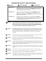
DANGER means:
Severe bodily injury or death can occur to you or other personnel if the DANGER statements found on this machine or in this Owner's Manual are ignored
or are not adhered to. Read and observe all DANGER statements found in
this Owner's Manual and on your machine.
WARNING means:
Injury can occur to you or to other personnel if the WARNING statements
found on your machine or in this Owner's Manual are ignored or are not
adhered to. Read and observe all WARNING statements found in this Owner's
Manual and on your machine.
CAUTION means:
Damage can occur to the machine or to other property if the CAUTION
statements found on your machine or in this Owner's Manual are ignored or are
not adhered to. Read and observe all CAUTION statements found in this
Owner's Manual and on your machine.
DANGER:
Failure to read the Owner's Manual prior to operating or servicing your Clarke American
Sanders machine could result in injury to you or to other personnel; damage to the machine or to other property could occur as well. You must have training in the operation of
this machine before using it. If you or your operator(s) cannot read English, have this
manual explained fully before attempting to operate this machine.
DANGER:
Sanding/finishing wood floors can create an explosive or combustible environment. Do not
operate this machine around solvents, thinners, alcohol, fuels, floor finishes, wood dust or
any other flammable materials. Cigarette lighters, pilot lights, electrical sparks and all
other sources of ignition should be extinguished or avoided. Keep work area well
ventilated.
DANGER:
Electrocution could occur if the machine is being serviced while the machine is connected to
a power source. Disconnect the power supply before servicing.
DANGER:
Electrocution or fire could occur if the machine is being operated with a damaged power cord.
Keep the power cord clear of the pad. Always lift the cord over the machine. Do not move
the machine by the power cord.
DANGER:
To avoid injury keep hands, feet, and loose clothing away from all moving parts on the
machine. Disconnect the power cord before replacing the pad, changing the abrasive, or when
servicing. Do not operate the machine unless all guards are in place. Never leave the machine
unattended while connected to a power source.
DANGER:
Dust generated from sanding wood floors can spontaneously ignite or explode. Promptly
dispose of any sanding dust in a metal container clear of any combustibles. Do not dispose
in a fire.
WARNING:
Shock hazard. Do not use the machine if it has been rained on or sprayed with water.
WARNING:
Injury can occur if protective clothing or equipment is not used while sanding. Always wear
safety goggles, protective clothing, and dust mask while sanding.
WARNING:
Any alterations of modifications of this machine could result in damage to the machine or injury
to the operator or other bystanders. Alterations or modifications not authorized by the
manufacturer voids any and all warranties and liabilities.
Clarke® American Sanders OBS-18/18 DC Operator's Manual
Page 3
Introduction & Machine Specifications
The OBS-18 or OBS-18DC can be used on a variety of surfaces. It is an ideal tool for wood flooring maintenance
and restoration work. It is also suitable for cleaning hard surfaces such as tile or Terrazzo.
See Table 1, Page 9 for power cable specifications
OBS-18
Model
Code Number
Voltage/Frequency
Amperage (A)
Motor
Pad Size
Orbits Per Minute
Orbit Dia.
Shipping Weight
Noise (dBA)
Vibration (m/s/s)
07076B
115V/60Hz
10
1 hp
12 x 18 inches
3600
1/4 inch
125 lbs.
74
16
OBS-18DC
07079B / 07116A /07086B
230V/50Hz
5
0.75 kw
305 x 457 mm
3000
6.4 mm
57 kg.
74
16
07081B
07083B / 07115A / 07087B
115V/60Hz
10
1hp
12 x 18 inches
3600
1/4 inch
125 lbs.
74
16
230V/50Hz
5
0.75kw
305 x 457mm
3000
6.4 mm
57 kg
74
16
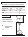
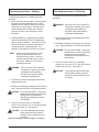
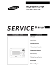
Machine Transportation
To transport the machine, follow this procedure:
1. Unplug machine from wall outlet and wrap cord.
2. Raise and lock the handle to the upright postion.
To lock the handle, press down on the locking lever
with your foot. See figure 1.
Figure # 1
3. Grasp the machine at the lifting sites and place in
cargo area. See figure 2.
WARNING:
The machine is heavy (125 lbs./
57kg). to avoid injury or damage to
the machine use a firm grip and
proper lifting technique. Get assistance if necessary.
4. Secure machine to prevent movement in cargo
area.
Figure # 2
Page 4
Clarke® American Sanders OBS-18/18 DC Operator's Manual
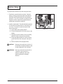
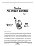
Machine Setup
To prepare the machine for use follow this procedure:
1. Familiarize yourself with the machine. Read all
danger, warning, and caution statements and the
Operation and Parts Manual before operating the
machine. If you or the operator are unable to read
English, have this manual fully explained before
attempting to operate this machine.
2. Install or replace pad. The pad should be replaced
if it has become matted down to a thickness of 3/
8" or less. To install or replace the pad, follow
these instructions:
a.) Lock handle in the upright position.
b.) Tilt the machine back until it fully rests on the
handle.
c.) Standing over the machine, remove existing
pad then center new pad over pad driver.
d.) Press pad against pad driver until the hooks
in the driver have set in the pad. See figure
3.
e.) Return machine to the upright position.
CAUTION:
Damage to the pad driver will occur if
the machine is operated without a pad
or with a pad that is 3/8" or thinner.
WARNING:
Never put yourself or let others be in
a position to get injured if the
machine should tip or fall, while
replacing the pad or changing
abrasive.
Clarke® American Sanders OBS-18/18 DC Operator's Manual
Figure # 3
Page 5
Operating Instructions - Sanding
To operate the machine as a sander follow this
procedure:
1. Move machine to work location. Decide the best
approach to sanding the desired area. When
sanding the area, work so that you are moving
away from the power supply. This will help to
avoid entanglement with the power cord and
reduce the need to move the power cord as
frequently.
2. Install the abrasive. Use the same procedure
outlined in MACHINE SETUP for installing the
pad, to install the abrasive. Peel the film off the
back of the abrasive; center the abrasive over
the pad and press it against the pad. The
adhesive on the abrasive will hold it to the pad.
NOTE:
When using screen abrasive, set the
screen on the floor then move the
machine over the screen. Lower the
machine until the pad comes to rest on
the screen. Make sure the screen is
centered on the pad.
WARNING:
Injury can occur if the machine is
connected to a power source while
installing the pad or abrasive.
Disconnect the machine before
installing the pad/abrasive.
Operating Instructions - Polishing
To operate the machine as a polisher follow this
procedure:
WARNING:
Injury can occur if the machine is
connected to a power source while
installing the pad or abrasive.
Disconnect the machine before
installing the pad/abrasive.
1. Connect the machine to an appropriately fused
and grounded circuit.
2. Release the handle by pressing up on the locking
lever. Bring the handle to a comfortable position.
CAUTION: Do not lock the handle. Locking the
handle will prevent the machine from
resting evenly on the pad and
diminish the machine performance
and reliability.
3. Push the interlock button (1), and apply
pressure to the levers (2). To stop the machine,
release the levers (2). See figure 4.
CAUTION:
To prevent damage to the flooring
and to reduce swirling, keep the
machine in motion while the motor
is running.
3. Connect the machine to an appropriately fused
and grounded circuit.
4. Release the handle by pressing up on the locking
lever. Bring the handle to a comfortable position.
CAUTION: Do not lock the handle. Locking the
handle will prevent the machine from
resting evenly on the pad and
diminish the machine performance
and reliability.
5. Push the interlock button (1), and apply
pressure to the levers (2). To stop the machine,
release the levers (2). See figure 4.
CAUTION: To prevent damage to the flooring
and to reduce swirling, keep the
machine in motion while the motor
is running.
NOTE: For sanding cuts and sandpaper, see page 9.
Page 6
Figure # 4
Clarke® American Sanders OBS-18/18 DC Operator's Manual
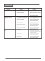
Troubleshooting
Problem
Motor will not start.
Motor fails to start / runs
sluggish.
Fuse / Circuit Breaker repeatedly
trips.
Cause
Action
No power.
Check power supply and connection
Interlock not depressed.
Depress Interlock before activating
control lever.
Defective switch/ Bad connection
Contact an authorized Clarke
American Sanders Dealer.
Low voltage from excessive length
or undersized extension cord.
Use a 14 Ga extension cord, not to
exceed 50' length.
Defective start capacitor.
Contact an authorized Clarke
American Sanders Dealer.
Defective start switch.
Contact an authorized Clarke
American Sanders Dealer.
Defective start/run capacitor
Contact an authorized Clarke
American Sanders Dealer.
Defective motor low voltage
Contact an authorized Clarke
American Sanders Dealer.
Low voltage.
Eliminate extension cord.
Locate power source closer to
work site. Have voltage checked by
a qualifed electrician.
Bad connection.
Contact an authorized Clarke
American Sanders Dealer.
Defective motor.
Contact an authorized Clarke
American Sanders Dealer.
Clarke® American Sanders OBS-18/18 DC Operator's Manual
Page 7
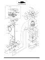
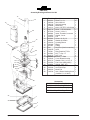
OBS-18
Assembly Drawing 1/03
1
20
2
5
4
3
19
4
6
3
17
18
21
72
73
16
8
74
22
76
11
26
24
25
23
79
12
14
27
15
7
71
10
13
80
46
28 29
45
44
47
48
49
30
77
31
32
81
43
42
41
40
70
69
59
58
68
66
65
64
63
62
61
60
50
51
33
35
36
34
37
38
52
39
44
57
44
Page 8
56
54
75
55
Clarke® American Sanders OBS-18/18 DC Operator's Manual
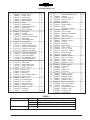
OBS-18
Assembly Drawing 1/03
Ref. #
Part No.
Description
1
2
3
4
5
6
7
8
9
10
11
12
13
85383A
30285A
50798A
50820A
50806A
40109A
50799A
50821A
50780A
920722
962957
170686
40522A
10250A
50797A
58013A
50930A
62667A
41312A
41314A
41311A
41313A
22906A
77195A
77234A
41419A
41418B
47709A
51523A
40160A
47378A
25907A
44667A
44668A
25907A
81220A
86110A
915044
10666A
925589
20901A
66982A
85718A
32519A
976551
Screw, 10-33 x 3/4
Handle, Front
Lever, Switch
Spring, Extension
Button, Interlock
Switch
Interlock, Main
Spring, Compression
Handle, Rear
Nut, 10-32 ESNA
Screw (CE)
Lock Nut
Cord, Interconnect
Cord, Interconnect (230V)
Strain Relief
Strain Relief (230V)
Cord, Retainer
Cover, Enclosure
Capacitor, Start (115V) 1
Capacitor, Start (230V) 1
Capacitor, Run (115V)
Capacitor, Run (230V)
Enclosure, Motor Starter
Label, Sanding Warning
Label, Heavy Object
Circuit Breaker (115V)
Circuit Breaker(230V)
Terminal, ¼ QD
Strain Relief
Switch, Start (115V)
Switch, Start (230V)
Screw, 8-32 x ½
Motor (115V)
Motor (230V)
Mainframe
Nut, ¼-20 Srtd. Flange 4
Screw 3/8-16 x 1
Key, 3/16 x 1
Kit, Spring Mount
Pin 1/8 x ½ Roll
Base, Pad Driver
Retainer, Eccentric
Screw, ½-13 x 3/4
Pad Driver
Pad, Red
14
15
16
17
18
19
20
21
22
23
24
25
26
27
28
29
30
31
32
33
34
35
36
37
38
Qty
8
1
2
2
1
2
1
1
1
8
1
1
1
1
1
1
1
1
Ref. #
Part No.
Description
Qty
39
40
41
42
43
44
45
46
47
48
49
50
51
52
53
54
55
56
57
58
59
60
61
62
63
64
65
66
67
68
69
70
71
72
73
74
75
76
77
78
79
80
81
---------50736A
66981A
87700A
62814A
920346
67474A
306802
Abrasive (sanding only)
Bearing
Retainer, Bearing
Screw, ¼-20 x ½
Eccentric
Palnut, ½"
Shaft, Handle
Plug
See Table 1 below
Bumper
Tube, Handle
Bushing, Strain Relief
Nut, Wire
Nut, 5/16-18 ESNA
Arm, Link LH
Washer, ½ Nylon
Tongue
Wheel, 5"
Axle, Wheel
Cam, Locking
Pin, ¼ x 3/4 Roll
Bolt, Cam Locking
Washer, Wear
Arm, Link RH
Washer, 3/8 Plain
Nut, 3/8-16 ESNA
Screw, 5/16-18 x 7/8
Screw, 5/16-18 x 2
Washer, 5/16 Lock
Clamp, Handle
Cord Hook
Rivet
Handle, Lift
Connector
Screw, 10-32 x 3/8
Washer #10 Ext
Washer, Bowed
Screw, ¼-20 x 5/8
Washer ¼ EXT
Screw, ¼-20x3/4 FT
Fan Cover OBS18
Tag, Warning
Plug NEMA 5-15P
Plug AU 1-10P
Plug UK 1-13P
Plug, Schuko
Pg. 9
1
1
5
1
4
1
1
1
1
1
1
1
1
1
1
1
1
1
2
1
1
1
4
1
1
1
1
1
1
1
cnt 20
31224B
69153B
627561
170667
920110
60448A
980215
509240
39857A
60529A
461404
925592
441301
980349
60447A
980645
920248
85812A
85817A
980652
442001
64325A
930005
54930A
170667
85833A
980603
980681
962822
980614
84233A
52465A
70175A
911248
40023A
45609A
40073A
1
1
1
3
1
1
4
1
2
1
1
1
1
1
1
1
1
1
1
2
1
1
2
1
1
1
1
2
2
4
4
1
1
1
1
1
1
TABLE 1
Electrical System
115V~ 60Hz
230V~50 Hz
Part No.
50991A
40524A
40523A
50870A
Specification
50' 14- S0 Gray Rubber Jacket w/NEMA 5-15P Plug
15m HO7RNF 3G1.0 mm2 w/AU1-10P Plug
15m HO7RNF 3G1.0 mm2 w/Schuko Plug
15m HO5VVF 3G1.5 mm2 Yellow Jacket w/UK1-13P
Clarke® American Sanders OBS-18/18 DC Operator's Manual
Page 9
OBS-18 DC
Assembly Drawing and Parst List 1/03
14
13
15
26
12
16
11
10
17
9
18
{
}
8
19
20
21
22
7
23
27
6
Ref. #
1
2
3
4
5
5
6
7
8
9
10
11
12
13
14
15
16
17
18
19
20
21
22
23
24
25
26
27
28
Part No.
930124
38239A
38015A
25908B
44671A
44673A
87700A
80092A
34287A
54765A
85383A
980982
35242A
53644A
837304
Ref.
30407B
797301
915044
81217A
980646
32404A
87617A
50275A
68806A
68807A
38109A
40545A
10478A
5
70401A
50951A
976550
50712A
4
24
Description
Rivet 3/16 x 19/32
Skirt, OBS-18
Shroud, Housing
Mainframe
Motor, 1HP TFFC 115V/60Hz
Motor, 1 HP 230V/60Hz
Screw, ¼-20 x ½
Insert, Threaded, 10-32UNF
Gasket, Cover
Fan
Screw, 10-32 x ¾
Washer, #10 Plain
Housing, Blower
Elbow
O'Ring
Bag Dust (See Accessories)
Hose
Ring, Retaining 5/8 Ext
Key, 3/16 Sq. x 1
Nut, ¼-20
Washer, ¼ Plain
Cover, Blower Housing
Washer, Felt ½ x 1¼ x ¼
Fan Cover (OBS-18DC)
Weight, Skirt 103/4
Weight, Skirt 17
Seal, Dust Pipe
Motor Fan
Asm., Blower Housing Cover
(includes 7, 8, 21 & 22)
Qty
16
1
1
1
1
1
3
4
1
1
4
4
1
1
1
2
2
1
3
3
1
1
1
1
1
2
1
1
Accessories
Paper Dust Bag (2 per)
Cloth Dust Bag
12 x 18 White Pad (20 per)
Paper Dust Bag w/Bun
3
25
2
1
Page 10
Clarke® American Sanders OBS-18/18 DC Operator's Manual
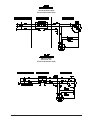
OBS-18 & 18DC
120v 60 Hz & 230v 50Hz
Electrical Schematic 10/98
OBS-18 & 18DC
230v 50 Hz "CE"
Electrical Schematic 10/98
Clarke® American Sanders OBS-18/18 DC Operator's Manual
Page 11
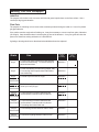
Sanding Cuts and Sandpaper
Initial Cut
The purpose of the initial cut is to remove old finish and gross imperfections on the floor surface. Use a
course (20-36 grit) grain abrasive.
Final Cuts
The purpose of a finishing cut is to remove the scratches produced during the initial cut. Use a fine (60-80
grit) grain abrasive.
If the surface remains rough after a finishing cut, it may be necessary to use an even finer grain of abrasive
(80-100grit). Care should be taken in selecting the grit size of the abrasive. A very fine grain will close the
pores on a wood floor making admission of a stain difficult.
If glazing or burning should occur the abrasive has dulled and must be replaced.
Grain
Standard
Grade
Part #/Qty.
Use
20 grit
For removing gross imperfections and restoring
evenness to old flooring. To remove buildup of
paints and varnishes
945950/10
36 grit
For the first sanding of new flooring (maple, oak).
For removing minor imperfections and finishes
from old flooring.
945951/20
60 grit
60 grit
screen mesh
For clean-up from initial cut 36 grit.
945954/20
945960/20
80 grit
80 grit
screen mesh
For final sanding of certain hardwoods. For
clean-up of cuts (60 grit).
945955/20
945961/20
100 grit
100 grit
screen mesh
For final sanding of certain hardwoods and
conifers where a smooth surface is desired.
945956/20
945962/20
120 grit
screen mesh
For final sanding of certain hardwoods and
conifers where a smooth surface is desired.
For leveling after initial finish coat.
945963/20
150 grit
screen mesh
For scratching surface between coats of finish
945964/20
180 grit
screen mesh
For surface roughing between coats of finish.
945965/20
Page 12
Professional
Grade
Part #/Qty.
Clarke® American Sanders OBS-18/18 DC Operator's Manual
PRODUCT SUPPORT BRANCHES
U. S. A. Locations
HEAD OFFICE
European Locations
PRODUCTION FACILITIES
ALTO U.S. Inc., St. Louis, Missouri
16253 Swingley Ridge Road, Suite 200
Chesterfield, Missouri 63017-1725
PRODUCTION FACILITIES
Clarke®, Springdale, Arkansas
2100 Highway 265
Springdale, Arkansas 72764
(479) 750-1000
Customer Service - 1-800-253-0367
Technical Service - 1-800-356-7274
American Lincoln®, Bowling Green, Ohio 43402
1100 Haskins Road
SERVICE FACILITIES
Clarke® , Carlstadt, New Jersey 07072
150 Commerce Road
(201) 460-4774
Clarke®, Elk Grove, Illinois 60007
2280 Elmhurst Road
(847) 956-7900
Clarke®, Denver, Colorado 80204
1955 West 13th Ave.
(303) 623-4367
Clarke®, Houston, Texas 77040
7215 North Gessner Road
SALES AND SERVICE FACILITIES
American Lincoln® / Clarke®, Madison Heights,
Michigan 48071-0158
29815 John R.
(810) 544-6300
American Lincoln® / Clarke®, Marietta, Georgia 30062
1355 West Oak Common Lane
(770) 973-5225
Clarke®
Clarke American Sanders
A.L. Cook
Customer Service Headquarters and Factory
2100 Highway 265
Springdale, Arkansas 72764
(479) 750-1000
Technical Service
1-800-356-7274
Clarke® American Sanders OBS-18/18 DC Operator's Manual
ALTO Danmark A/S, Aalborg
Blytaekkervej 2
DK-9000 Aalborg
+45 72 18 21 00
ALTO Danmark A/S, Hadsund
Industrikvarteret
DK-9560 Hadsund
+45 72 18 21 00
SALES SUBSIDIARIES
Clarke® Canada Ltd., Rexdale Ontario
24 Constellation Ct.
(416) 675-5830
ALTO Overseas Inc., Sydney (Australia)
1B/8 Resolution Drive
Caringbah NSW 2229
+61 2 9524 6122
ALTO Cleaning Systems Asia Pte Ltd., Singapore
No. 17 Link Road
Singapore 619034
+65 268 1006
ALTO Deutschland GmbH, Bellenberg (Germany)
Guido-Oberdorfer-Straße 2-8
89287 Bellenberg
+49 0180 5 37 37 37
ALTO Cleaning Systems (UK) Ltd., Penrith
Gilwilly Industrial Estate
Penrith
Cumbria CA11 9BN
+44 1768 868 995
ALTO France S.A. Strasbourg
B.P. 44, 4 Place d’Ostwald
F-67036 Strasbourg
Cedex 2
+33 3 8828 8400
ALTO Nederland B.V. Vianen
Stuartweg 4C
NL-4131 NJ Vianen
+31 347 324000
ALTO Sverige AB, Molndal (Sweden)
Aminogatan 18
Box 4029
S-431 04 Molndal
+46 31 706 73 00
ALTO Norge A/S, Oslo (Norway)
Bjornerudveien 24
N-1266
+47 2275 1770
Page 13
Clarke® American Sanders U. S. Warranty
This Clarke American Sanders Industrial/Commercial Product is warranted to be free from defects in
materials and workmanship under normal use and service for a period of two years from the date of purchase, when operated and maintained in accordance with Clarke American Sanders' Maintenance and
Operations Instructions.
This warranty is extended only to the original purchaser for use of the product. It does not cover normal
wear parts such as electrical cable, rubber parts, hoses and motor brushes.
If difficulty develops with the product, you should:
(a). Contact the nearest authorized Clarke American Sanders repair location or contact the Clarke American
Sanders Service Operations Department, 2100 Highway 265, Springdale, Arkansas 72764, for the nearest
authorized Clarke American Sanders repair location. Only these locations are authorized to make repairs to
the product under this warranty.
(b). Return the product to the nearest Clarke American Sanders repair location. Transportation charges to
and from the repair location must be prepaid by the purchaser.
(c). Clarke American Sanders will repair the product and or replace any defective parts without charge within
a reasonable time after receipt of the product.
Clarke American Sanders' liability under this warranty is limited to repair of the product and/or replacement
of parts and is given to purchaser in lieu of all other remedies, including INCIDENTAL AND CONSEQUENTIAL
DAMAGES.
THERE ARE NO EXPRESS WARRANTIES OTHER THAN THOSE SPECIFIED HEREIN. THERE ARE NO
WARRANTIES WHICH EXTEND BEYOND THE DESCRIPTION OF THE FACE HEREOF. NO WARRANTIES,
INCLUDING BUT NOT LIMITED TO WARRANTY OF MECHANTABILITY, SHALL BE IMPLIED. A warranty
registration card is provided with your Clarke American Sanders product. Return the card to assist Clarke
American Sanders in providing the performance you expect from your new floor machine.
Clarke, 2100 Highway 265, Springdale, Arkansas 72764.
Clarke American Sanders reserves the right to make
changes or improvements to its machine without notice.
Always use genuine Clarke American Sanders Parts for repair.
Division of
2100 Highway 265
Springdale, Arkansas, 72764