1
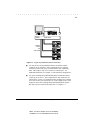
. . . . . . . . . . . . . . . . . . . . . . . . . . . . . . Keyboard/Monitor/Mouse Switch Box User Guide Part Number 242757-001 COMPAQ CONFIDENTIAL - NEED TO KNOW REQUIRED . . . . . . . . . . . . . . . . . . . . . . . . . . . . . . NOTICE The information in this publication is subject to change without notice. COMPAQ COMPUTER CORPORATION SHALL NOT BE LIABLE FOR TECHNICAL OR EDITORIAL ERRORS OR OMISSIONS CONTAINED HEREIN, NOR FOR INCIDENTAL OR CONSEQUENTIAL DAMAGES RESULTING FROM THE FURNISHING, PERFORMANCE, OR USE OF THIS MATERIAL. This publication contains information protected by copyright. No part of this publication may be photocopied or reproduced in any form without prior written consent from Compaq Computer Corporation. The software described in this guide is furnished under a license agreement or nondisclosure agreement. The software may be used or copied only in accordance with the terms of the agreement. Product names mentioned herein may be trademarks and/or registered trademarks of their respective companies. 1996 Compaq Computer Corporation. All rights reserved. Printed in the U.S.A. Compaq registered United States Patent and Trademark Office. Compaq Keyboard/Monitor/Mouse Switch Box User Guide First Edition (October 1996) Part Number 242757-001 Writer: Kristi Wishon Project: Notice Comments: File Name:B-notice.doc Last Saved On:8/29/96 4:24 PM . . . . . . . . . . . . . . . . . . . . . . . . . . . . . . iii Contents Chapter 1 Introduction Compaq Keyboard/Monitor/Mouse Switch Box Features ........................................1-1 Configurations ........................................................................................................1-2 Chapter 2 Installation Attaching the Slide Rail Brackets............................................................................2-1 Preparing the Rack-Mount Brackets ........................................................................2-2 Rack-mount Installation ..........................................................................................2-2 Cover Panel Installation ..........................................................................................2-3 Compaq Keyboard/Monitor/Mouse Switch Box System Installation........................2-4 Initial Power-up ......................................................................................................2-5 Keyboard/Monitor/Mouse Switch Box Startup Behavior .........................................2-6 Computer Startup Behavior.....................................................................................2-6 Configuring the Keyboard/Monitor/Mouse Switch Box..........................................2-6 Switching Between Computers................................................................................2-7 Unattended Reboot..................................................................................................2-7 Chapter 3 Basic Switch Functions Unit Operation ........................................................................................................3-1 Switching Computers ..............................................................................................3-1 Checking Port/Computer Status...............................................................................3-2 Advanced Switch Operations ..................................................................................3-2 Scanning System Computers ...................................................................................3-3 Compaq Keyboard/Monitor/Mouse Switch Box User Guide Writer: Kristi Wishon Project: Table of Contents Comments: File Name:C-toc.doc Last Saved On:9/6/96 2:51 PM . . . . . . . . . . . . . . . . . . . . . . . . . . . . . . iv Displaying Version Information and Device Settings ..............................................3-4 Basic Switch Functions continued Saving the Hardware Configuration ........................................................................3-5 Resetting the Mouse and Keyboard .........................................................................3-5 Setting a Scanning Pattern.......................................................................................3-6 Assigning Names to Switch Ports............................................................................3-7 Changing the Menu Attributes.................................................................................3-7 Changing the Status Flag Attributes ........................................................................3-9 Assigning Specific Device Types ..........................................................................3-11 Changing the Security Password ...........................................................................3-12 Resetting the Unit .................................................................................................3-13 Making Connections Under Power ........................................................................3-13 Chapter 4 Alternate Configurations Paired Switch Configurations ..................................................................................4-1 Tiered Switch Configurations..................................................................................4-2 Connecting Tiers while the System is Powered Up..................................................4-3 Switching Tiered Systems .......................................................................................4-3 Appendix A Compaq Keyboard/Monitor/Mouse Switch Box Specifications Product Specifications............................................................................................A-1 Appendix B Command Summary Keyboard Sequences for CCR ................................................................................ B-1 Appendix C Troubleshooting Tips Writer: Kristi Wishon Project: Table of Contents Comments: File Name:C-toc.doc Last Saved On:9/6/96 2:51 PM . . . . . . . . . . . . . . . . . . . . . . . . . . . . . . v Appendix D Regulatory Notices Appendix E Power Cord Set Requirements General Requirements............................................................................................ E-1 Country-Specific Requirements.............................................................................. E-2 Index Compaq Keyboard/Monitor/Mouse Switch Box User Guide Writer: Kristi Wishon Project: Table of Contents Comments: File Name:C-toc.doc Last Saved On:9/6/96 2:51 PM . . . . . . . . . . . . . . . . . . . . . . . . . . . . . . 1-1 Chapter 1 Introduction The Compaq Keyboard/Monitor/Mouse Switch Box is a device that switches a single keyboard, mouse, and monitor between multiple Compaq computers. The Keyboard/Monitor/Mouse Switch Box is a space-efficient 1 U height (1.75-inch) device and is available in four- and eight-port models. This chapter provides an overview of the product features, functionality, and sample configurations. Compaq Keyboard/Monitor/Mouse Switch Box Features The Keyboard/Monitor/Mouse Switch Box products provide Compaq users with a complete Compaq solution for their server computing needs. You can use the Keyboard/Monitor/Mouse Switch Box in various configurations to connect from 2 to 64 servers. The features of the Keyboard/Monitor/Mouse Switch Box include: ■ Console Configuration Reporting (CCR) - Console Configuration Reporting displays system-related information on the monitor, such as power-up test data and configuration menus. ■ Programmable Scanning - You can evaluate system performance by sequentially scanning any or all of the computers in the system. Programmable scanning allows you to determine which computers to include as well as the duration of the connection. ■ Configuration NVRAM - NVRAM (non-volatile RAM) makes it easy to set configuration information using commands entered from the keyboard. The NVRAM stores the resulting configuration until you decide to change the information, even if the unit loses power. ■ Hardware Reset Switch - If the keyboard or mouse communication is disrupted, you can press this switch to reset the unit. Compaq Keyboard/Monitor/Mouse Switch Box User Guide Writer: Kristi Wishon Project: Introduction Comments: File Name:D-ch01.doc Last Saved On:9/6/96 2:50 PM . . . . . . . . . . . . . . . . . . . . . . . . . . . . . . 1-2 Introduction ■ External Keypad Jack - The Keyboard/Monitor/Mouse Switch Box has an external keypad jack to support rack-mounted Compaq products. In this configuration, the switch is mounted behind a door in a cabinet and the optional keypad is mounted outside the cabinet for easy access. ■ Password Protection - For protection against unauthorized users, the Compaq Keyboard/Monitor/Mouse Switch Box provides a password option for security purposes. Configurations There are many ways to configure your Compaq Keyboard/Monitor/Mouse Switch Box in order to meet your specific organizational needs. Additional information on configuring multiple Keyboard/Monitor/Mouse Switch Boxes can be found in Chapter 4. ■ A single Keyboard/Monitor/Mouse Switch Box is used to connect four or eight servers. In this configuration, the keyboard, monitor, and mouse are connected directly to the unit by their respective cables. You can connect the Keyboard/Monitor/Mouse Switch Box to servers located in the same or adjoining racks. See Figure 1-1. Writer: Kristi Wishon Project: Introduction Comments: File Name:D-ch01.doc Last Saved On:9/6/96 2:50 PM . . . . . . . . . . . . . . . . . . . . . . . . . . . . . . 1-3 Master Switch Keyboard, Mouse, and Video Cables HYDR-001.EPS Figure 1-1. Single Keyboard/Monitor/Mouse Switch Box ■ You can pair two Keyboard/Monitor/Mouse Switch Box units to connect up to 16 computers. In this configuration, two eight-port switches are placed one on top of another with a cable connecting them. This requires only 2U (3.5 inches) of vertical space. For additional information, see Chapter 4, “Paired Switch Configurations.” ■ You can tier multiple Keyboard/Monitor/Mouse Switch Box units to connect up to 64 servers. This configuration is often referred to as a “master/slave” system. It is illustrated in the example below, with the slave unit’s device port connected to one of the computer ports on the original or master unit. Multiple Keyboard/Monitor/Mouse Switch Box units can be tiered from the master unit. See Figure 1-2. Compaq Keyboard/Monitor/Mouse Switch Box User Guide Writer: Kristi Wishon Project: Introduction Comments: File Name:D-ch01.doc Last Saved On:9/6/96 2:50 PM . . . . . . . . . . . . . . . . . . . . . . . . . . . . . . 1-4 Introduction Master Switch Keyboard, Mouse, and Video Cables HYDR-002.EPS Slave Switch Figure 1-2. Tiered Configuration Writer: Kristi Wishon Project: Introduction Comments: File Name:D-ch01.doc Last Saved On:9/6/96 2:50 PM . . . . . . . . . . . . . . . . . . . . . . . . . . . . . . 2-1 Chapter 2 Installation This chapter provides installation information for the Compaq Keyboard/Monitor/Mouse Switch Box. WARNING: To reduce the risk of personal injury or damage to the equipment be sure that; the leveling feet are extended to the floor and supporting the full weight of the rack. Each rack should be level and stable. Racks that are not coupled together require the installation of stabilizing feet. This must be accomplished before performing any work on the rack. WARNING: Risk of personal injury. The rack may become unstable if more than one component is extended for any reason. Always ensure that the rack is adequately stabilized before extending a component outside the rack. Extend only one component at a time. Attaching the Slide Rail Brackets The figure below shows how to attach the slide rail brackets to the Keyboard/Monitor/Mouse Switch Box. Make sure that the front end of the rack-mount brackets angle out away from the unit. Compaq Keyboard/Monitor/Mouse Switch Box User Guide Writer: Kristi Wishon Project: Installation Comments: File Name:E-ch02.doc Last Saved On:9/6/96 3:18 PM . . . . . . . . . . . . . . . . . . . . . . . . . . . . . . 2-2 Installation HYDR-003.EPS Figure 2-1. Attaching slide rail brackets Preparing the Rack-Mount Brackets Prepare the rack-mount brackets for cable management in the rack by attaching the plastic cable ties. The cable ties snap into place, with the tie on the outside of the bracket. See Figure 2-2. After the cable ties are in place, install the rack-mount brackets in the rack by sliding the two back tabs in the back mounting rail. Secure the rack-mount brackets in the front mounting rail with two 6mm screws each, making sure to use only the top and bottom holes. The middle will be used for attaching the front cover panel after the unit is fully installed. Also install the cable rod in the back of the unit in the two keyhole-shaped holes. Push the rod down to lock it in place. Writer: Kristi Wishon Project: Installation Comments: File Name:E-ch02.doc Last Saved On:9/6/96 3:18 PM . . . . . . . . . . . . . . . . . . . . . . . . . . . . . . 2-3 HYDR-010.EPS Figure 2-2. Snapping cable ties into place Rack-mount Installation Slide the Keyboard/Monitor/Mouse Switch Box into the rack-mount brackets until it snaps into place, as shown in Figure 2-3. HYDR-007.EPS Figure 2-3. Sliding the Keyboard/Monitor/Mouse Switch Box into rack-mount brackets Compaq Keyboard/Monitor/Mouse Switch Box User Guide Writer: Kristi Wishon Project: Installation Comments: File Name:E-ch02.doc Last Saved On:9/6/96 3:18 PM . . . . . . . . . . . . . . . . . . . . . . . . . . . . . . 2-4 Installation Cover Panel Installation After the unit is fully installed, secure the front cover panel using the middle hole, as shown below. HYDR-008.EPS Figure 2-4. Securing the front cover panel Compaq Keyboard/Monitor/Mouse Switch Box System Installation Use the following procedure for system installation: WARNING: To reduce the risk of electric shock or damage to your equipment, make sure the power cord is disconnected from the Switch Box. 1. Connect the keyboard, monitor, and mouse cables to the switch monitor, keyboard, and mouse connectors as shown below. Note that all keyboard and mouse cables are 6-pin mini-DIN PS/2 style, and all the video cables are 15-pin VGA style. Writer: Kristi Wishon Project: Installation Comments: File Name:E-ch02.doc Last Saved On:9/6/96 3:18 PM . . . . . . . . . . . . . . . . . . . . . . . . . . . . . . 2-5 Monitor Computer 3 Monitor Power Cord Connector HYDR-004.EPS Keyboard Mouse Computer 3 Computer 3 Power Keyboard Mouse Switch Figure 2-5. Keyboard/Monitor/Mouse Switch Box Connectors 2. Decide which computer is to be connected to port 1. Connect the computer’s keyboard and mouse to the jacks marked K and M, respectively, beneath the port labeled One. Connect the computer’s monitor to the 15-pin VGA connector. Bundle and label the cables for easy identification. 3. Repeat step 2 for all remaining computers to be connected to the Keyboard/Monitor/Mouse Switch Box. Bundle the cables to the cable rod with Velcro cable ties. Then route the cables out the slot in the rackmount bracket. Use the plastic cable ties to bundle the cables. See Figure 2-6. Cable Rod Velcro Ties Plastic Cable Ties HYDR-009.EPS Figure 2-6. Bundling cables with cable ties Compaq Keyboard/Monitor/Mouse Switch Box User Guide Writer: Kristi Wishon Project: Installation Comments: File Name:E-ch02.doc Last Saved On:9/6/96 3:18 PM . . . . . . . . . . . . . . . . . . . . . . . . . . . . . . 2-6 Installation WARNING: To reduce the risk of electric shock or damage to your equipment, do not disable the power cord grounding feature. This equipment is designed to be connected to a grounded (earthed) power outlet that is easily accessible to the operator. The grounding plug is an important safety feature. 4. Connect the power cord to the Keyboard/Monitor/Mouse Switch Box. Initial Power-up It is important that you power up the Keyboard/Monitor/Mouse Switch Box first, then the computers. This is because when the servers boot up, their drivers send device settings to the switch. These settings are then stored in the switch NVRAM. Power-up the system as follows: 1. Power up the switch by pressing the power switch located on the rear panel to the on (1) position. 2. Power up the computers. Keyboard/Monitor/Mouse Switch Box Startup Behavior Power up the Keyboard/Monitor/Mouse Switch Box first. During startup, the unit does the following: ■ Identifies the mouse and keyboard and puts them into default states. ■ Switches to port number 1 by default, and displays the number “1” in the status flag displayed on the monitor. If the status flag default setting has been changed to Names mode, the status flag displays the port name instead of the port number. If a status flag is not being shown on the monitor, make sure that it is connected and powered up. Writer: Kristi Wishon Project: Installation Comments: File Name:E-ch02.doc Last Saved On:9/6/96 3:18 PM . . . . . . . . . . . . . . . . . . . . . . . . . . . . . . 2-7 Computer Startup Behavior During startup the computers send device settings to the Keyboard/Monitor/Mouse Switch Box. The unit then generates standard responses to these commands and allows the computers to boot successfully without actually being physically connected to the devices. Once you have the switch installed you can save these settings to non-volatile RAM (NVRAM). See Chapter 3 for additional information. Configuring the Keyboard/Monitor/Mouse Switch Box When you first power up the Keyboard/Monitor/Mouse Switch Box, no configuration is needed for normal switching operation. For tailoring the unit to meet your specific needs, such as assigning unique names for the computers, or displaying the computers by their assigned name or port number, see Chapter 3. Switching Between Computers Switching from one computer to another is a simple process with the Keyboard/Monitor/Mouse Switch Box. Switching disconnects the keyboard, mouse, and monitor from one computer and connects them to another. The steps are as follows: 1. Press Print Scrn. 2. Select the computer you want to switch to by using the Up and Down arrow keys, or by pressing the numeric key that corresponds to the computer’s port number. 3. Press Enter. Since the Print Scrn key is used to start the switching process, you cannot use it to print a screen in the normal way. To print the screen, simply press Print Scrn twice. For more information on switching, see Chapter 3. Compaq Keyboard/Monitor/Mouse Switch Box User Guide Writer: Kristi Wishon Project: Installation Comments: File Name:E-ch02.doc Last Saved On:9/6/96 3:18 PM . . . . . . . . . . . . . . . . . . . . . . . . . . . . . . 2-8 Installation Whenever you switch between two computers, the Keyboard/Monitor/Mouse Switch Box reconfigures the keyboard and mouse using the settings stored in its memory. For example, if the current computer selected has Caps Lock turned On, but the user is switching to a second computer that has Caps Lock turned Off, then the unit turns Caps Lock Off to match the setting for the second computer. Unattended Reboot After a power outage, each server connected to the Keyboard/Monitor/Mouse Switch Box reboots (if designed to do so), without operator intervention, when power returns. The switch generates responses to ensure that the reboot is successful and that the Keyboard/Monitor/Mouse Switch Box is ready to switch between computers. Writer: Kristi Wishon Project: Installation Comments: File Name:E-ch02.doc Last Saved On:9/6/96 3:18 PM . . . . . . . . . . . . . . . . . . . . . . . . . . . . . . 3-1 Chapter 3 Basic Switch Functions This chapter provides information on basic switch functions such as resetting the Keyboard/Monitor/Mouse Switch Box, connecting the keyboard and mouse while the system is powered up, and basic and advanced commands. Unit Operation Basic operation of the Keyboard/Monitor/Mouse Switch Box is achieved through the keyboard and a series of windows and menus that appear on the monitor. You can switch between computers and check port/computer status by using these menus. Console Configuration Reporting (CCR) is the interface used to communicate with the Keyboard/Monitor/Mouse Switch Box. CCR is accessed by pressing the Print Scrn key. The user then communicates directly with the switch using the system keyboard and monitor. For more information on navigating the menus or lists, refer to “Appendix B, Command Summary.” Switching Computers To switch the keyboard, monitor, and mouse from one computer in the system and connect it to another, proceed as follows: 1. Press Print Scrn. The CCR Selection window appears on the monitor. The computers are listed in order of port or computer name, as determined by the Menu Attribute choice. 2. Select the computer you want to switch to by using the Up and Down arrow keys, or by pressing the numeric key that corresponds to the computer’s port number, and press Enter. 3. Press Esc to exit CCR and remove the CCR Selection window from the monitor. The status flag window returns (if enabled) to the display to indicate the currently connected computer. Compaq Keyboard/Monitor/Mouse Switch Box User Guide Writer: Kristi Wishon Project: Basic Switch Functions Comments: File Name:F-ch03.doc Last Saved On:9/6/96 1:17 AM . . . . . . . . . . . . . . . . . . . . . . . . . . . . . . 3-2 Basic Switch Functions Checking Port/Computer Status You can confirm which ports are currently active and whether each port has a computer or a slave switch connected by the following: 1. Press Print Scrn. The CCR Selection window appears on the monitor. The symbols after the Port or Name columns show the status of the port as follows: Table 3-1 Port/Computer Status Type of Symbol Symbol Meaning Plus + Computer connected and running Asterisk * Slave connected and running 2. Press Esc to exit the CCR selection window. Advanced Switch Operations Many switch functions are available that allow you to tailor your system to meet your unique needs. Like the basic operation of the unit, system configuration is achieved through the keyboard and the Console Configuration Reporting. Some of the advanced operations include : ■ Scanning the computers connected to the switch ■ Displaying switch firmware version and settings ■ Saving switch settings ■ Resetting the mouse and keyboard Writer: Kristi Wishon Project: Basic Switch Functions Comments: File Name:F-ch03.doc Last Saved On:9/6/96 1:17 AM . . . . . . . . . . . . . . . . . . . . . . . . . . . . . . 3-3 ■ Setting up a special scan pattern ■ Assigning unique names to the computers connected to the switch ■ Displaying computers by name or port number in the windows ■ Changing the position and color of the operation menus/windows ■ Changing the attributes of the status flag ■ Assigning a specific monitor type to a certain port/computer ■ Assigning a password to protect against unauthorized users For information on making specific entries and selections in the menus, refer to “Appendix B, Command Summary.” Scanning System Computers When the unit is in scan mode, it automatically switches from port to port in a sequential manner. You can modify the scan order so that specific computers are included in a certain sequence and for a variable duration. For more information, see “Setting a Scanning Pattern.” To place the unit in scan mode, proceed as follows: 1. Press Print Scrn. The CCR Selection window appears. 2. Press F2 and the Advanced Menu screen appears. The highlight is in the Commands menu. 3. Using the Up and Down arrow keys, move the highlight to Scan and press Enter. At this point, the switch enters the scan mode and the display returns to the status flag. You can press Esc at any time prior to pressing Enter to cancel the operation. 4. To cancel the scan mode, press any key or move the mouse. The scan stops at the currently connected computer. Compaq Keyboard/Monitor/Mouse Switch Box User Guide Writer: Kristi Wishon Project: Basic Switch Functions Comments: File Name:F-ch03.doc Last Saved On:9/6/96 1:17 AM . . . . . . . . . . . . . . . . . . . . . . . . . . . . . . 3-4 Basic Switch Functions Displaying Version Information and Device Settings To help when troubleshooting or supporting this system, the switch firmware version number can be displayed along with specific keyboard and mouse information for the currently selected computer. To show this information, proceed as follows: 1. Press Print Scrn. The CCR Selection window appears. 2. Press F2 and the Advanced Menu screen appears. The highlight is in the Commands menu. 3. Using the Up and Down arrow keys, move the highlight to Version and press Enter. This window appears: Version Firmware X.XX Hardware XX Port 1 Computer Name Keyboard Mouse ENABLED ENABLED Rate 2C Rate 100 LEDs 2 Res 2 Mode 2 Type 101 Type Gen Writer: Kristi Wishon Project: Basic Switch Functions Comments: File Name:F-ch03.doc Last Saved On:9/6/96 1:17 AM . . . . . . . . . . . . . . . . . . . . . . . . . . . . . . 3-5 The window contains keyboard information including enabled/disabled, typematic rate, LED settings, port mode and keyboard type. The mouse information includes enabled/disabled, sample rate, resolution, and mouse type. 4. Press Esc to remove the Version window. Saving the Hardware Configuration Whenever servers are added or removed from the system, or whenever there is a change in the mouse or monitor, the configuration settings should be saved to non-volatile memory (NVRAM) within the unit. If the settings are not saved, they will be lost whenever the switch loses power or is turned off. To save settings to memory, proceed as follows: CAUTION: If settings are not saved and switch power is lost, it may be necessary to reboot each computer in the system to reestablish keyboard and mouse communications. 1. Press Print Scrn. The CCR Selection window appears on the monitor. 2. Press F2 and the Advanced Menu screen appears. The highlight is in the Commands menu. 3. Using the Up and Down arrow keys, move the highlight to Snapshot and press Enter. The hardware settings for all connected ports are now saved to memory. Resetting the Mouse and Keyboard To reset the mouse and keyboard settings for the selected computer, perform the following: 1. Press Print Scrn. The CCR Selection window appears on the monitor. Compaq Keyboard/Monitor/Mouse Switch Box User Guide Writer: Kristi Wishon Project: Basic Switch Functions Comments: File Name:F-ch03.doc Last Saved On:9/6/96 1:17 AM . . . . . . . . . . . . . . . . . . . . . . . . . . . . . . 3-6 Basic Switch Functions 2. Press F2 and the Advanced Menu screen appears. The highlight is in the Commands menu. 3. Using the Up and Down arrow keys, move the highlight to Reset and press Enter. The mouse and keyboard are now reset. Setting a Scanning Pattern The unit defaults to a standard scan routine that sequentially connects each computer to the monitor, keyboard and mouse. However, you can configure a scan of all or any of the servers in any particular scan pattern. To create a scan pattern, proceed as follows: 1. Press Print Scrn. The CCR Selection window appears on the monitor. 2. Press F2 and the Advanced Menu screen appears. The highlight is in the Commands menu. Press the Right arrow key to move the highlight to the Setup menu. 3. Using the Up and Down arrow keys, move the highlight to Scan and press Enter. The Scan Pattern Setup window appears with the first port position (or computer name) highlighted. 4. Using the keyboard keys, select the port number of the first computer to be included in the scan. 5. Press the Tab or Right Arrow key to move the highlight to the Sec column and use the keyboard keys to enter a time value in seconds that you want this computer connected to the monitor/keyboard (before switching to the next computer in the scan). 6. Press the Down Arrow key to move the highlight to the next port in the Port column and repeat step 5. To delete unwanted ports from the bottom of the scan list in the Scan Pattern Setup window, place the highlight on the topmost port to be removed and press the Delete key (not DEL on the numeric keypad). Writer: Kristi Wishon Project: Basic Switch Functions Comments: File Name:F-ch03.doc Last Saved On:9/6/96 1:17 AM . . . . . . . . . . . . . . . . . . . . . . . . . . . . . . 3-7 7. When you have finished setting the scan pattern, press Enter. You can press Esc at any time prior to pressing enter to retain the previous scan pattern. Pressing the F2 key while in this screen, will return all Port and Sec values to factory defaults. 8. To exit CCR, press Esc. Assigning Names to Switch Ports In order to easily identify the computers connected to the switch, it is often helpful to assign unique names to each port. In a network environment, the names can be the same as those assigned in the network for each computer. Assign names as follows: 1. Press Print Scrn. The CCR Selection window appears on the monitor. 2. Press F2 and the Advanced Menu screen appears. The highlight is in the Commands menu. Press the Right arrow key to move the highlight to the Setup menu. 3. Using the Up and Down arrow keys, move the highlight to Names and press Enter. The Port Naming window appears with the first port position (or computer name) highlighted. 4. Move the highlight to the Port entry for which the computer name is to be entered or changed. Type in the name of computer using up to 12 alphanumeric characters. Legal characters are A-Z, 0-9, and the dash character. Lowercase letters are converted to uppercase. Press Back Space to delete an incorrect entry. 5. If necessary, repeat step 4 for each of the computers in the system that are to be named. Press Enter to save the computer name(s) in NVRAM. You can press Esc at any time prior to pressing Enter to cancel the operation. 6. To exit CCR, press Esc. Compaq Keyboard/Monitor/Mouse Switch Box User Guide Writer: Kristi Wishon Project: Basic Switch Functions Comments: File Name:F-ch03.doc Last Saved On:9/6/96 1:17 AM . . . . . . . . . . . . . . . . . . . . . . . . . . . . . . 3-8 Basic Switch Functions Changing the Menu Attributes You can change the “look” or visual appearance of the Console Configuration Reporting (CCR) system menus to suit your own preferences. Adjustments can be made to the menus so that: ■ The menu is positioned in a convenient location on the display ■ The computers are listed by port or by name, whichever is desired in the appropriate menus ■ The character height is suitable for display ■ The colors are suitable ■ The CCR Selection window appears on the display for a certain period of time To change menu attributes, proceed as follows: 1. Press Print Scrn. The CCR Selection window appears on the monitor. 2. Press F2 and the Advanced Menu screen appears. The highlight is in the Commands menu. Press the Right arrow key to move the highlight to the Setup menu. 3. Using the Up and Down arrow keys, move the highlight to CCR and press Enter. The CCR Attributes window appears. 4. Highlight the setting(s) you want to change and use the + and - keys on the numeric keypad to obtain the desired value. As you select different values, the effect of the changes is reflected immediately on the display. NOTE: Certain changes that you make to CCR menu attributes may distort the menu and windows on the display. The distortion can make the display difficult to read. If this occurs, you can reset the Keyboard/Monitor/Mouse Switch Box to its default CCR settings by pressing Esc, Esc, Print Scrn, F10, Y, Enter. Writer: Kristi Wishon Project: Basic Switch Functions Comments: File Name:F-ch03.doc Last Saved On:9/6/96 1:17 AM . . . . . . . . . . . . . . . . . . . . . . . . . . . . . . 3-9 5. When you’ve completed all the desired changes, press Enter to save the changes to NVRAM. You can press Esc at any time prior to pressing Enter to cancel the operation and retain the previous settings. The following table describes each of the available menu attributes. Table 3-2 Menu Attributes Setting Effect on Menu/Window Appearance Resolution Affects the size of the menu and windows as they appear on the display. Choose from values of 320, 480, and 640. The lower the value, the larger the size. Height Affects the size of the text in the menu and windows. The larger the value, the larger the text. Horizontal/Vertical Determines the position of the menu or window on the display. Background Determines the menu or window background color. Highlight Determines the menu or window highlight color. Text Determines the menu or window text color. Delay Time This is the time in seconds that the CCR Selection window is delayed before appearing on the display after Print Screen is pressed. This delay may be increased so that the window is not a distraction when performing simple port switching operations at the keyboard. Order Determines the way the computers are listed; numerically by port number, or alphabetically by assigned name. Compaq Keyboard/Monitor/Mouse Switch Box User Guide Writer: Kristi Wishon Project: Basic Switch Functions Comments: File Name:F-ch03.doc Last Saved On:9/6/96 1:17 AM . . . . . . . . . . . . . . . . . . . . . . . . . . . . . . 3-10 Basic Switch Functions Changing the Status Flag Attributes The status flag indicates the currently connected computer and can be set to appear on the screen whenever the system is operating. You can change how and where the flag appears on the screen by changing one or more of the following attributes: ■ Appearance on the screen: none, timed or constant ■ Position on the screen ■ Color and opaqueness To change the status flag attributes, proceed as follows: 1. Press Print Scrn. The CCR Selection window appears on the monitor. 2. Press F2 and the Advanced Menu screen appears. The highlight is in the Commands menu. Press the Right arrow key to move the highlight to the Setup menu. 3. Using the Up and Down arrow keys, move the highlight to Flag and press Enter. The Flag Attributes window appears. 4. Highlight the setting(s) you want to change and use the + and - keys to adjust the values. The following table describes each of the available menu attributes. Table 3-3 Flag Attributes Setting Values and Effect on Flag Appearance Writer: Kristi Wishon Project: Basic Switch Functions Comments: File Name:F-ch03.doc Last Saved On:9/6/96 1:17 AM . . . . . . . . . . . . . . . . . . . . . . . . . . . . . . 3-11 Enabled FLAG OFF = Flag does not appear PORTS ON = Flag indicates the connected port number NAMES ON = Flag indicates the connected computer by name PORTS TIMED = Port number displays for 5 seconds after connection NAMES TIMED = Name displays for 5 seconds after connection Row Select values in the range of 0 to 14 to position the flag vertically on the screen Column Select values in the range of 0 to 25 to position the flag horizontally on the screen Color Select values in the range of 0 to 7 for the flag color Text Select values in the range of 0 to 7 for the flag text color Mode Choose between Opaque and Transparent 5. Press Enter to retain the settings. You can press Esc at any time prior to pressing Enter to cancel the operation and retain the previous settings. 6. Press Esc to exit CCR. Assigning Specific Device Types In situations where one or more of the computers need a special type of monitor or device, it may be necessary to assign that device type to the port number associated with that computer. When tiering you must make the master switch aware of the slaves through this assignment. Assign a device type as follows: 1. Press Print Scrn. The CCR Selection window appears on the display. Compaq Keyboard/Monitor/Mouse Switch Box User Guide Writer: Kristi Wishon Project: Basic Switch Functions Comments: File Name:F-ch03.doc Last Saved On:9/6/96 1:17 AM . . . . . . . . . . . . . . . . . . . . . . . . . . . . . . 3-12 Basic Switch Functions 2. Press F2 and the Advanced Menu screen appears. The highlight is in the Commands menu. Press the Right Arrow key to move the highlight to the Setup menu. 3. Using the Up and Down arrow keys, move the highlight to Devices and press Enter. The Device Setting window appears. 4. To assign a monitor type, highlight the port you want and use the + and - keys to obtain the value that corresponds to the particular monitor. To assign a slave switch to a port, highlight the port and use the + and keys to obtain the appropriate 4-port or 8-port values. 5. Press Enter to retain the settings. You can press Esc at any time prior to pressing Enter to cancel the operation. 6. Press Esc to remove the Advanced Menu screen from the display. Changing the Security Password Advanced server applications should usually be protected against unauthorized users. CCR provides a simple screen and keyboard lock for the unit. The factory default password is “password.” To change the password, proceed as follows: 1. Press Print Scrn. The CCR Selection window appears on the display. 2. Press F2 and the Advanced Menu screen appears. The highlight is in the Commands menu. Press the Right Arrow key to move the highlight to the Setup menu. 3. Using the Up and Down arrow keys, move the highlight to Security and press Enter. The Security Configuration window appears. You must always provide a password to access the fields on this screen. Once the current password is entered, the other fields on the screen are activated. Writer: Kristi Wishon Project: Basic Switch Functions Comments: File Name:F-ch03.doc Last Saved On:9/6/96 1:17 AM . . . . . . . . . . . . . . . . . . . . . . . . . . . . . . 3-13 4. Enter the new password, and then press Enter. Passwords can be up to eight characters. This field is case sensitive. Then enter the new password again for confirmation, and press Enter. When entered correctly, the password field shows “CHANGED” to indicate that your new password has been accepted. 5. Wait time is the amount of time the system must be idle before the screen and keyboard lock is initiated. To change this setting, highlight the value and use the + and - keys to obtain the desired setting. 6. The Mode field should be set to energy only when EnergyStar ™ compliant monitors are being used. This allows the monitors to go into low power mode when the wait time has elapsed. Do not use energy mode with non-compliant monitors. 7. To test your password settings, highlight Test and press Enter. The display shows the security screen. Pressing a key or moving the mouse will cause the system to prompt you for your password. 8. Press Enter to retain the settings. You can press Esc at any time prior to pressing Enter to cancel the operation. 9. Press Esc to remove the Advanced Menu screen from the display. Resetting the Unit If the keyboard or mouse locks up, you can push the Reset button on the back panel to reset the switch. Pressing the Reset button may allow you to recover the device settings without power cycling the computers. Making Connections Under Power You can connect additional computers to the switch while it is running. When you power up the newly connected computers, the switch recognizes them, and you can switch to the new computers without taking any additional steps. Compaq Keyboard/Monitor/Mouse Switch Box User Guide Writer: Kristi Wishon Project: Basic Switch Functions Comments: File Name:F-ch03.doc Last Saved On:9/6/96 1:17 AM . . . . . . . . . . . . . . . . . . . . . . . . . . . . . . 3-14 Basic Switch Functions You can also connect the mouse and/or keyboard to the switch while the system is powered up. When you connect a new device, the switch recognizes it, and configures it to the settings of the currently selected computer. This technique allows replacement of failed devices without having to restart the system. NOTE: When new computers are added to the switch, or when existing connections are changed, the new configurations should be saved in NVRAM. See “Saving the Hardware Configuration.” Writer: Kristi Wishon Project: Basic Switch Functions Comments: File Name:F-ch03.doc Last Saved On:9/6/96 1:17 AM . . . . . . . . . . . . . . . . . . . . . . . . . . . . . . 4-1 Chapter 4 Alternate Configurations There are other ways to configure your system, including paired switch configurations and tiered switch configurations. This chapter provides brief descriptions, installation instructions, and hardware requirements for these alternate configurations. Paired Switch Configurations Two eight-port Keyboard/Monitor/Mouse Switch Box units can be connected or paired together to effectively double the capacity of the system. To operate two switch box units in a paired configuration, mount one on top of the other and interconnect them by means of the pairing kit cables. The Interconnect Cable Kit (pairing kit) consists of one RJ45 interconnecting cable and three ‘Y’ cables as shown below. The pairing kit is required for a paired configuration and is available through your Compaq Authorized Reseller. HYDR-005.EPS System 1 to 8 Video Keyboard System 1-1 to 1-8 Mouse Figure 4-1. Paired switch configuration Compaq Keyboard/Monitor/Mouse Switch Box User Guide Writer: KRISTI A. WISHON Project: Alternate Configurations Comments: File Name:G-ch04.doc Last Saved On:9/6/96 1:19 AM . . . . . . . . . . . . . . . . . . . . . . . . . . . . . . 4-2 Alternate Configurations Tiered Switch Configurations In tiered systems, you can connect additional switches to ports on a master unit. That is, switches can be tiered in master/slave configurations to allow one master switch to switch between computers or other switch units. Tiering simply involves linking the slave units’ physical keyboard, mouse, and monitor connections to one of the computer ports on the master unit. For example, one eight-port master unit can accommodate eight slave switch units. This system with eight servers connected to each of the eight slave switches would provide a 1x64 concentration. An example of a tiered switch configuration is shown below. System 1 - 8 System 9 - 16 HYDR-006.EPS Figure 4-2. Tiered configuration When connecting a slave unit to one of the ports of the master unit, you need to indicate this connection to the master unit by performing the previously described “Assigning Specific Device Types” procedure, but entering slave unit designation for the associated port number instead of a monitor type. Use the designation 4port for a four-port slave and 8port for an eight-port slave. CCR allows slave ports to be treated much like ports on the master switch. It may be helpful to name each slave unit as previously described under “Assigning Names to Switch Ports.” Writer: KRISTI A. WISHON Project: Alternate Configurations Comments: File Name:G-ch04.doc Last Saved On:9/6/96 1:19 AM . . . . . . . . . . . . . . . . . . . . . . . . . . . . . . 4-3 Connecting Tiers while the System is Powered Up If necessary, you can connect a master unit to a slave unit while the system is powered on. This technique can be used to isolate any problems with a minimum disruption to the system. When plugging a master Keyboard/Monitor/Mouse Switch Box into a slave unit, you must first connect the mouse and video cables, then connect the keyboard cable. This is because the master unit interprets the keyboard connection as the slave unit’s power up. At this point the master unit sends initialization codes to the slave unit, triggering device configuration. Switching Tiered Systems To switch the Keyboard/Monitor/Mouse Switch Box to a computer that is connected to the master through a slave unit, proceed as follows: 1. Press Print Scrn. The CCR Selection window appears on the monitor. 2. Type the number of the port to which the slave unit is connected followed by a dash and the number of the port (on the slave unit) to which the computer is connected. For example, to switch to the computer connected to port 3 of a slave unit connected to port 1 of the master, press Print Scrn, 1, -, 3. If the computer/slaves are listed in the window by name (as described in “Assigning Names to Switch Ports”), then type the assigned name of the computer. If no slave unit is connected to the selected master port, the command is canceled when you enter the slave number. 3. Press Enter. Compaq Keyboard/Monitor/Mouse Switch Box User Guide Writer: KRISTI A. WISHON Project: Alternate Configurations Comments: File Name:G-ch04.doc Last Saved On:9/6/96 1:19 AM . . . . . . . . . . . . . . . . . . . . . . . . . . . . . . A-1 Appendix A Compaq Keyboard/Monitor/Mouse Switch Box Specifications Table A-1 Compaq Keyboard/Monitor/Mouse Switch Box Specifications Dimensions Height (1U = 1.75 inches) 1.75 in (4.5 cm) Depth 10.80 in (27.7 cm) Width 17.00 in (68.6 cm) Weight 9.1 lb (4.1 kg) Input Power Requirements Rated Voltage 100 -240 VAC Rated Frequency 50 - 60 Hz Rated Input Current 1.4 - 0.7 A Temperature Range Maximum Ambient Operating Temperature 50° - 122° F (10° - 50° C) -40° - 185° F (-40° - 85° C) Ambient Storage and Shipping Temperature 122° F (50° C) Maximum Internal Rack Temperature for the Switch Box Relative Humidity (noncondensing) Operating 20% - 80% 5% - 90% Nonoperating Compaq Keyboard/Monitor/Mouse Switch Box User Guide Writer: Kristi Wishon Project: Specifications Comments: File Name:H-apa.doc Last Saved On:9/6/96 3:19 PM . . . . . . . . . . . . . . . . . . . . . . . . . . . . . . A-2 Specifications Video Modes Supported VGA, SVGA, XGA Writer: Kristi Wishon Project: Specifications Comments: File Name:H-apa.doc Last Saved On:9/6/96 3:19 PM . . . . . . . . . . . . . . . . . . . . . . . . . . . . . . B-1 Appendix B Command Summary Table B-1 Keyboard Sequences for CCR (Console Configuration Reporting) Keyboard Entry PRINT SCRN Results Pressing once activates CCR. Pressing twice sends the print screen command to the selected computer. ESCAPE (Esc) Terminates the command or selection without executing ENTER Executes the current selection, command, or submenu Up Arrow Moves up one field or up one item in the menu Down Arrow Moves down one field or down one item in the menu Right Arrow Moves one field to the right, wraps downward or highlights adjacent menu TAB Left Arrow SHIFT + TAB Moves one field to the left, wraps downward or highlights adjacent menu + Increases the current field value - Decreases the current field value Page Up Displays the previous screenful of a list Page Down Displays the next screenful of a list Home Displays the top screenful of a list End Displays the bottom screenful of a list Compaq Keyboard/Monitor/Mouse Switch Box User Guide Writer: Kristi Wishon Project: Command Summary Comments: File Name:I-apb.doc Last Saved On:9/6/96 3:19 PM . . . . . . . . . . . . . . . . . . . . . . . . . . . . . . B-2 Command Summary Writer: Kristi Wishon Project: Command Summary Comments: File Name:I-apb.doc Last Saved On:9/6/96 3:19 PM . . . . . . . . . . . . . . . . . . . . . . . . . . . . . . C-1 Appendix C Troubleshooting Tips Table C-1 System Troubleshooting Symptom No video on one computer No video or CCR on any computer Probable Cause Recommended Solution Loose video connection Reconnect video cable. Defective video cable Replace video cable. Computer powered down Power up the computer connected to that port. No power to unit Establish power connection. Loose monitor connection No power to unit CCR colors or setup incompatible Reconnect monitor. Check power switch. Reconnect power cable. Check ac outlet for power. Reset CCR colors to defaults. Press reset button. No video on switching Keyboard did not initialize Keyboard incompatible Computer powered down Reset keyboard (and mouse) with rear panel reset switch. Replace keyboard. Power up the computer connected to that port. Compaq Keyboard/Monitor/Mouse Switch Box User Guide Writer: Kristi Wishon Project: Troubleshooting Tips Comments: File Name:J-apc.doc Last Saved On:9/6/96 3:19 PM . . . . . . . . . . . . . . . . . . . . . . . . . . . . . . C-2 Troubleshooting Tips Keyboard error on boot, one computer Loose keyboard connection Check that all cables are well seated. Ensure that mouse and keyboard cables are not swapped. Replace keyboard cable. Defective cable continued Writer: Kristi Wishon Project: Troubleshooting Tips Comments: File Name:J-apc.doc Last Saved On:9/6/96 3:19 PM Table C-1 continued Symptom Keyboard error on boot, all computers Probable Cause Loose keyboard connection Recommended Solution Check that all cables are well seated. Replace keyboard. Incompatible or defective keyboard Keyboard strokes shifted (swaps upper case for lower case) Computer left keyboard shifter state when last connected Press both SHIFT keys Mouse error on boot, one computer Loose mouse connection Check that all cables are well seated. Ensure that mouse/keyboard cables are not swapped. Defective mouse cable Replace mouse cable. Using serial port on computer Install PS/2-to-serial protocol converter. Loose mouse connection Check that all cables are well seated. Ensure that mouse/keyboard cables are not swapped. Using serial port on computer Install PS/2-to-serial protocol converter. Incompatible or defective mouse Replace mouse with PS/2 or mouse-port compatible mouse. Mouse displays ballistic behavior Computer left mouse in indeterminate state Reset mouse through CCR or reset switch. Mouse pointer frozen on display Mouse not initialized Reset mouse through CCR or reset switch. Unit switches from one system to the next at will Scan mode initiated Halt scanning by pressing any key or moving mouse. Mouse error on boot, all computers Writer: Kristi Wishon Project: Troubleshooting Tips Comments: File Name:J-apc.doc Last Saved On:9/6/96 3:19 PM . . . . . . . . . . . . . . . . . . . . . . . . . . . . . . C-4 Troubleshooting Tips Writer: Kristi Wishon Project: Troubleshooting Tips Comments: File Name:J-apc.doc Last Saved On:9/6/96 3:19 PM . . . . . . . . . . . . . . . . . . . . . . . . . . . . . . D-1 Appendix D Regulatory Notices Federal Communications Commission Notice Part 15 of the Federal Communications Commission (FCC) Rules and Regulations has established Radio Frequency (RF) emission limits to provide an interference-free radio frequency spectrum. Many electronic devices, including computers, generate RF energy incidental to their intended function and are, therefore, covered by these rules. These rules place computers and related peripheral devices into two classes, A and B, depending upon their intended installation. Class A devices are those that may reasonably be expected to be installed in a business or commercial environment. Class B devices are those that may reasonably be expected to be installed in a residential environment (i.e., personal computers). The FCC requires devices in both classes to bear a label indicating the interference potential of the device as well as additional operating instructions for the user. The rating label on the device shows which class (A or B) the equipment falls into. Class B devices have an FCC ID on the label. Class A devices do not have an FCC ID on the label. Once the class of the device is determined, refer to the following corresponding statement. Class A Equipment This equipment has been tested and found to comply with the limits for a Class A digital device, pursuant to Part 15 of the FCC Rules. These limits are designed to provide reasonable protection against harmful interference when the equipment is operated in a commercial environment. This equipment generates, uses, and can radiate radio frequency energy and, if not installed and used in accordance with the instructions, may cause harmful interference to radio communications. Operation of this equipment in a residential area is likely to cause harmful interference, in which case the user will be required to correct the interference at personal expense. Canadian Notice This Class A digital apparatus meets all requirements of the Canadian Interference-Causing Equipment Regulations. Avis Canadien Cet appareil numérique de la classe A respecte toutes les exigences du Règlement sur le matériel brouilleur du Canada. Compaq Keyboard/Monitor/Mouse Switch Box User Guide Writer: Kristi Wishon Project: Regulatory Notices Comments: File Name:K-apd.doc Last Saved On:9/5/96 10:58 AM . . . . . . . . . . . . . . . . . . . . . . . . . . . . . . D-2 Regulatory Notices Class B Equipment This equipment has been tested and found to comply with the limits for a Class B digital device, pursuant to Part 15 of the FCC Rules. These limits are designed to provide reasonable protection against harmful interference in a residential installation. This equipment generates, uses, and can radiate radio frequency energy and, if not installed and used in accordance with the instructions, may cause harmful interference to radio communications. However, there is no guarantee that interference will not occur in a particular installation. If this equipment does cause harmful interference to radio or television reception, which can be determined by turning the equipment off and on, the user is encouraged to try to correct the interference by one or more of the following measures: ■ Reorient or relocate the receiving antenna. ■ Increase the separation between the equipment and receiver. ■ Connect the equipment into an outlet on a circuit different from that to which the receiver is connected. ■ Consult the dealer or an experienced radio or television technician for help. Canadian Notice This Class B digital apparatus meets all requirements of the Canadian Equipment Regulations. Interference-Causing Avis Canadien Cet appareil numérique de la classe B respecte toutes les exigences du Règlement sur le matériel brouilleur du Canada. Modifications The FCC requires the user to be notified that any changes or modifications made to this device that are not expressly approved by Compaq Computer Corporation may void the user's authority to operate the equipment. Cables Connections to this device must be made with shielded cables with metallic RFI/EMI connector hoods in order to maintain compliance with FCC Rules and Regulations. Writer: Kristi Wishon Project: Regulatory Notices Comments: File Name:K-apd.doc Last Saved On:9/5/96 10:58 AM . . . . . . . . . . . . . . . . . . . . . . . . . . . . . . D-3 European Union (EU) Notice Products with the CE Marking comply with both the EMC Directive (89/336/EEC) and the Low Voltage Directive (73/23/EEC) issued by the Commission of the European Community. Compliance with these directives implies conformity to the following European Norms: ■ EN55022 (CISPR 22) - Electromagnetic Interference ■ EN50082-1 (IEC801-2, IEC801-3, IEC801-4) - Electromagnetic Immunity ■ EN60950 (IEC950) - Product Safety Japanese Notice Compaq Keyboard/Monitor/Mouse Switch Box User Guide Writer: Kristi Wishon Project: Regulatory Notices Comments: File Name:K-apd.doc Last Saved On:9/5/96 10:58 AM . . . . . . . . . . . . . . . . . . . . . . . . . . . . . . E-1 Appendix E Power Cord Set Requirements The voltage select switch feature of your switch box permits it to operate from any line voltage between 100-120 or 200-240 volts AC. The power cord set (appliance coupler, flexible cord, and wall plug) you received with your switch box meets the requirements for use in the country where you purchased your equipment. Power cord sets for use in other countries must meet the requirements of the country where you use the switch box. For more information on power cord set requirements, contact your Authorized Compaq Dealer. General Requirements The requirements listed below are applicable to all countries: ■ The length of the power cord must be at least 6.00 feet (1.8 m) and a maximum of 9.75 feet (3.0 m). ■ All power cord sets must be approved by an acceptable accredited agency responsible for evaluation in the country where the power cord will be used. ■ The power cord set must have a minimum current capacity of 10A and a nominal voltage rating of 125 or 250 volts AC, as required by each country’s power system. ■ The appliance coupler must meet the mechanical configuration of an EN 60320/IEC 329 Standard Sheet C7 connector for mating with the appliance inlet on the switch box. Compaq Keyboard/Monitor/Mouse Switch Box User Guide Writer: Kristi Wishon Project: Power Cord Set Requirements Comments: File Name:L-ape.doc Last Saved On:9/6/96 3:19 PM . . . . . . . . . . . . . . . . . . . . . . . . . . . . . . E-2 Power Cord Set Requirements Country-Specific Requirements Use the following table to identify the appropriate accredited agency in your country. Table E-1 Power Cord Set Requirements - By Country Country Australia Austria Belgium Canada Denmark Finland France Germany Italy Japan Netherlands Norway Sweden Switzerland United Kingdom United States Accredited Agency EANSW OVE CEBC CSA DEMKO FIMKO UTE VDE IMQ JIS KEMA NEMKO SEMKO SEV BSI UL Applicable Note Numbers 1 1 1 2 1 1 1 1 1 3 1 1 1 1 1 2 Writer: Kristi Wishon Project: Power Cord Set Requirements Comments: File Name:L-ape.doc Last Saved On:9/6/96 3:19 PM . . . . . . . . . . . . . . . . . . . . . . . . . . . . . . E-3 Notes: 1. Flexible cord must be <HAR> Type HO5VV-F, 3-conductor, 1.0 mm2 conductor size. Power cord set fittings (appliance coupler and wall plug) must bear the certification mark of the agency responsible for evaluation in the country where it will be used. 2. Flexible cord must be Type SV or equivalent, No. 18 AWG, 3-conductor. Wall plug must be a two-pole grounding type with a NEMA 5-15P (15A, 125V) or NEMA 6-15) (15A 250V) configuration. 3. Appliance coupler, flexible cord, and wall plug must bear a "T" mark and registration number in accordance with the Japanese Dentori Law. Flexible cord must be Type VCT or VCTF, 3-conductor, o.75 mm2 conductor size. Wall plug must be a two-pole grounding type with a Japanese Industrial Standard C8303 (15A, 250V) configuration. Compaq Keyboard/Monitor/Mouse Switch Box User Guide Writer: Kristi Wishon Project: Power Cord Set Requirements Comments: File Name:L-ape.doc Last Saved On:9/6/96 3:19 PM . . . . . . . . . . . . . . . . . . . . . . . . . . . . . . I-1 F Index Factory defaults 3-6 Flag Attributes 3-9 Features 1-1 A Alternate Configurations 4-1 Assigning Names 3-7 Assigning Specific Device Types 3-11 Attaching Rack Mount Brackets 2-1 H B Initial Power-up 2-4 Installation 2-1 Interconnect Cable Kit 4-1 Basic operation 3-1 Basic switch functions 3-1 Hardware Reset Switch 1-1 I K C Changing the Menu Attributes 3-7 Changing the Status Flag Attributes 3-9 Checking Port/Computer Status 3-2 Computer Startup Behavior 2-5 Configurations 1-2 Connecting Tiers while the System is Powered Up 4-3 Console Configuration Reporting (CCR) 1-1, 3-1, 3-7 Cover Panel Installation 2-2 Keyboard information 3-5 Keyboard sequences for CCR B-1 M Making Connections Under Power 3-13 Master/slave 1-3, 4-2 Maximum number of servers 1-3 Menu attributes 3-8 Mouse information 3-5 N D Displaying Version Information and Device Settings 3-4 Distortion of display 3-8 E External Keypad Jack 1-1 NVRAM 1-1, 2-4, 2-5, 3-5, 3-7, 3-8, 3-13 P Paired switch configurations 1-3, 4-1 Password 1-2, 3-12 Password, default 3-12 Power outage 2-6 Compaq Keyboard/Monitor/Mouse Switch Box User Guide Writer: Kristi Wishon Project: Index Comments: File Name:M-indx.doc Last Saved On:9/6/96 3:18 PM . . . . . . . . . . . . . . . . . . . . . . . . . . . . . . I-2 Index Power switch 2-4 Programmable Scanning 1-1 R Rack Mount Installation 2-2 Reset 3-13 Resetting the Mouse and Keyboard 3-5 S Saving the Hardware Configuration 3-5 Scanning System Computers 3-3 Setting a Scanning Pattern 3-6 Side Rail Brackets 2-1 Snapshot 3-5 Specifications A-1 Status flag 2-6, 3-1, 3-3, 3-9 Switch Box Startup Behavior 2-5 Switching Between Computers 2-5 Switching Computers 3-1 Switching Tiered Systems 4-3 T Tiered switch configurations 1-3, 4-1, 4-2 Troubleshooting C-1 U Unattended Reboot 2-7 Writer: Kristi Wishon Project: Index Comments: File Name:M-indx.doc Last Saved On:9/6/96 3:18 PM