1
IS4225 ScanGlove®
Laser Bar Code Scanner
Installation and User’s Guide
Disclaimer
Honeywell International Inc. (“HII”) reserves the right to make changes in
specifications and other information contained in this document without prior
notice, and the reader should in all cases consult HII to determine whether any
such changes have been made. The information in this publication does not
represent a commitment on the part of HII.
HII shall not be liable for technical or editorial errors or omissions contained
herein: nor for incidental or consequential damages resulting from the furnishing,
performance, or use of this manual.
This document contains propriety information that is protected by copyright. All
rights reserved. No part of this document may be photocopied, reproduced, or
translated into another language without the prior written consent of HII.
© 1999 - 2010 Honeywell International Inc. All rights reserved.
Web Address: www.honeywellaidc.com
Trademarks
Metrologic, MetroSelect, and ScanQuest are trademarks or registered
trademarks of Metrologic Instruments, Inc. or Honeywell International Inc.
Other product names mentioned in this manual may be trademarks or registered
trademarks of their respective companies and are the property of their respective
owners.
TABLE OF CONTENTS
Introduction........................................................................................................... 1
Scanner and Accessories..................................................................................... 1
Scanner Installation .............................................................................................. 2
Scanner Configuration to the Host System........................................................... 3
Parts of the Scanner............................................................................................. 4
Visual Indicators ................................................................................................... 5
Audible Indicators ................................................................................................. 6
Labels................................................................................................................... 7
Maintenance......................................................................................................... 8
Depth of Field ....................................................................................................... 9
Object Detection Device ..................................................................................... 10
Specifications ..................................................................................................... 12
Default Settings .................................................................................................. 13
Troubleshooting Guide ....................................................................................... 19
Regulatory Compliance ...................................................................................... 20
Patents ............................................................................................................... 23
Limited Warranty ................................................................................................ 24
Index................................................................................................................... 25
Customer Support .............................................................................................. 27
Technical Assistance ..................................................................................... 27
Product Service and Repair ........................................................................... 28
iii
INTRODUCTION
The IS4225 ScanGlove® is a fully automatic single-line laser barcode scanner.
The ScanGlove is designed to be used as a “hands-free” wearable scanner or a
stationary desktop scanner.
Every ScanGlove is equipped with an object detection technology that allows the
scanner to read bar codes automatically as the operator presents the bar code to
the scanner. Additional features include; 52 scan lines a second, short, or longrange activation and two universal glove sizes with left and right-hand
capabilities.
The IS4225 has built in decoding for applications that use a RS232, Keyboard
Wedge, Stand Alone Keyboard, Light Pen Emulation, or USB interfaces. All
models have Flash upgradeable firmware. For additional information on other
system interfaces, please call a Customer Service Representative.
SCANGLOVE MODEL NO.
IS4225-38
INTERFACE
USB Keyboard
IS4225-41D
RS232 with Breakaway Cable and DIN Connector
IS4225-47
PC Keyboard Wedge and Stand Alone Keyboard
IS4225-81
Full RS232 and Light Pen Emulation
SCANNER AND ACCESSORIES
PART NUMBER
IS4225
DESCRIPTION
IS4225 Laser Scanner
00-02258
Installation and User’s Guide
00-02544
MetroSelect® Single-Line Configuration Guide
45-45455
Black Adjustable Glove
If any item is missing or to order additional items, contact the dealer, distributor or contact a
customer service representative.
1
SCANNER INSTALLATION
1.
Turn off power to the host system.
2.
Connect the communication cable to the proper port on the host device.
3.
Turn on power to the host system.
When the IS4225 first receives power, the red LED will flash, the
green LED will flash, and then the scanner will beep once.
See power source caution statement on page 7 of this manual.
To maintain compliance with federal regulations 21 CFR, Part 1040.10,
section (f)(6) the scanner must be plugged into an electrical outlet with a
switch accessible to the user or be powered by a host system containing a
switch that will disable power to the scanner.
2
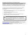
SCANNER CONFIGURATION TO THE HOST SYSTEM
The IS4225 is shipped from the factory pre-configured to a set of default
parameters. It may be necessary to change the default parameters to match the
host system’s requirements or to enable additional scanner functions. For a list
of possible parameter settings, refer to the Default Settings section of this guide.
To modify the scanner’s default parameters follow the steps below using the
bar codes located in the MetroSelect Single-Line Configuration Guide
(PN 00-02544).
1.
Scan the ENTER CONFIGURATION MODE bar code to enter configuration mode.
The scanner will beep three times.
2.
Scan the bar code(s) for the desired parameter(s).
The scanner will beep once.
3.
Scan the EXIT CONFIGURATION MODE bar code to exit and save the new
parameter settings. The scanner will beep three times.
If during the configuration process, there is a need to return the
scanner to the original factory settings, scan the recall defaults bar
code in the MetroSelect Configuration Guide. All settings selected
during that session or any previous sessions are discarded when you
scan the recall defaults code.
The IS4225 with RS232 interface can also be configured using MetroSet®2 which
is a PC-based utility software and available for download at
www.honeywellaidc.com. In addition, this interface can be configured using serial
configuration mode. For details, refer to the MetroSelect® Single-Line
Configuration Guide (PN 00-02544.)
3
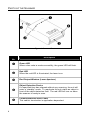
PARTS OF THE SCANNER
Figure 1. Scanner Parts
Item
No.
Description
LED
Green
When a bar code is read successfully, the green LED will flash.
LED
Red
When the red LED is illuminated, the laser is on.
Red Output Window (Laser Aperture)
Object Detection Device
If a specified time has elapsed without any scanning, the unit will
enter a “standby” mode. To reactivate the unit, place an object in
front of the object detection field. The red LED will turn on when
the scanner is ready to scan.
Cable
Communication/Power
This cable’s termination is application dependent.
4
VISUAL INDICATORS
There is a red and a green LED located on the top of the scanner. When the
scanner is on, the flashing or constant, illumination of the LEDs indicates the
status of the current scan and the scanner.
No Red LED
Illumination of the LEDs will not occur if the scanner has
remained dormant for a specified time and the scanner is
not receiving power from the host. To reactivate the unit,
direct the output window up then down toward the object.
Red Flash;
Green Flash;
Steady Red
When the scanner first receives power, the red LED will
flash, followed by the green LED, and then the unit will
beep once. The red LED will stay on after it flashes once.
Steady Red
When the laser is on, the red LED will be on. This occurs
when an object is detected in the scan field. If the scanner
cannot detect a bar code within approximately 2.5 seconds,
the unit will go into standby mode then the red LED will
shut off indicating that the laser is no longer on.
Steady Red
LED; Green
Flash
When the scanner successfully reads a bar code, the green
LED will flash and the unit will beep once. If the green LED
does not flash or the scanner does not beep, then the bar
code was not successfully read.
Repetitive Red
LED Flashing
The red LED will flash repeatedly when the object detection
device is detecting a stationary object in the scan field. To
eliminate this disturbance, direct the scan window toward a
different location or remove the stationary object from the
object detection field.
Steady Green
LED
After a successful scan, the scanner transmits the data to
the host device. When the host is not ready to receive the
information, the green LED will remain on until data can
transmit.
5
AUDIBLE INDICATORS
The scanner provides sounds to signal certain conditions. To change the volume
(four settings are available) or turn the beeper off, refer to Scanner Operation:
Beeper Options in the MetroSelect Single-Line Configuration Guide (PN 0002544).
One Beep
When the scanner first receives power, the red LED will
flash, followed by the green LED, and then the scanner
will beep once. After the scanner performs this start-up
sequence, the scanner is ready to scan.
When the scanner successfully reads a bar code, the
green light will flash and the unit will beep once. If the
green LED does not flash or the scanner does not beep,
then the bar code read is not successful.
Razzberry Tone
If, upon power up, the scanner emits a razzberry tone the
scanner has failed diagnostics.
The scanner can be configured to emit a
razzberry tone when the timeout occurs during
communication between the host and scanner.
Refer to Scanner Operation: Communication
Timeout Options in the MetroSelect Single-Line
Guide.
Three Beeps
When entering configuration mode, the green LED will
flash three times while the scanner simultaneously beeps
three times. When exiting configuration mode, the same
visual and audible indications will occur. After the
sequence is completed, the red LED will turn off.
The scanner can be programmed to emit three
beeps when the timeout occurs during
communication between the host and scanner.
Refer to Scanner Operation: Communication
Timeout Options in the MetroSelect Single-Line
Guide.
6
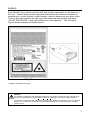
LABELS
Each IS4225 has a serial number label and a laser class label on the bottom of
the unit. These labels provide important information like; date and location of
manufacture, model number, serial number, caution statements and laser class.
There is also text molded into the top of the case near the window that says,
“AVOID EXPOSURE - laser light emitted from this aperture”. The following
Figure shows examples of these labels*.
Figure 2. Caution and Serial Number Labels*
* Labels not shown to scale.
Caution:
To maintain compliance with applicable standards, all circuits connected to the scanner must
meet the requirements for SELV (Safety Extra Low Voltage) according to EN/IEC 60950-1.
To maintain compliance with standard CSA-C22.2 No. 60950-1/UL 60950-1 and norm EN/IEC
60950-1, the power source should meet applicable performance requirements for a limited
power source.
7
MAINTENANCE
Smudges and dirt on the unit’s window can interfere with the unit’s performance.
If the window requires cleaning, use only a mild glass cleaner containing no
ammonia. When cleaning the window, spray the cleaner onto a lint free, nonabrasive cleaning cloth then gently wipe the window clean.
8
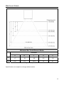
DEPTH OF FIELD
Minimum Bar Code Element Width
Standard
A
B
C
D
E
m
m
.17
.19
.25
.33
.53
mil
6.8
7.5
10.4
13
21
Figure 3. Depth of Field
Specifications are subject to change without notice.
9
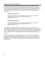
OBJECT DETECTION DEVICE
An object detection device located behind the window initiates the scanning
process. The device is active as long as power is applied to the unit. When the
device detects an object, the green LED will flash. When the laser decodes a bar
code, the scanner transmits the data to the host system and emits a beep to
show that decoding is complete. The object detection range is configurable for
two ranges.
•
Short Range Activation
The object detection device initiates the scan process if it senses an
object anywhere from the face of the window out to
approximately 4" to 7".
•
Long Range Activation
The object detection device initiates the scan process if it senses an
object anywhere from the face of the window out to
approximately 9" to 13".
If the object is removed from the field during the scanning process, the laser
turns off and the scanner re-enters "standby" mode. However, if the object stays
in the field, the laser remains on for up to 2.5 seconds trying to detect another bar
code. If the scanner does not detect a bar code, the scanner re-enters "standby"
mode. To reactivate the scanning sequence, remove the object and present
another.
If the same symbol stays in the field after a successful scan, the laser stays on
for approximately 7.5 seconds and then turns off. This prevents unintentional
reads of the same bar code. To read the same symbol more than once, remove
the object from the scan field for approximately 1 second and then present the
symbol again.
10
OBJECT DETECTION DEVICE
Figure 4. Object Detection Field
Please note certain ambient light conditions may interfere with the object
detection mechanism, resulting in false activation of the scanner. To mitigate the
problem, please try one of the following suggestions:
1.
2.
3.
4.
Avoid mounting the scanner directly facing the ambient light source.
Avoid mounting the scanner facing a light-colored or reflective surface.
Avoid mounting the scanner towards a surface at a distance close to the
long range (9" – 11") of object detection
Configure the object detection range to short (4" – 7").
11
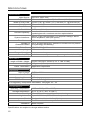
SPECIFICATIONS
IS4225 SPECIFICATIONS
OPERATIONAL
Light Source:
Depth of Field:
Width of Scan Field:
Scan Speed:
Scan Pattern:
Min Bar Width:
650 nm ± 10nm VLD
25 mm to 203 mm (1" to 8") for .33 mm (13 mil) bar code
70 mm (2.8”) @ 25mm (1.0”); 280 mm (11”) @ 200 mm (8”)
52 scans lines per second
Single scan line
0.173 mm (6.8 mil)
Decode Capability:
Autodiscriminates all standard bar codes; for other
symbologies call a customer service representative
System Interfaces:
RS232, Light Pen Emulation, PC Keyboard Wedge, Stand
Alone Keyboard, USB (low speed)
Print Contrast:
35% minimum reflectance difference
Number of
Characters Read:
Up to 80 data characters (Maximum number will vary based
on symbology and density)
Roll, Pitch, Skew:
30°, 56°, 58° @ 100 mm distance
Sweep Angle:
Beeper Operation:
Indicators (LED):
60°
3 tones or no beep
red = laser on, ready to scan
green = good read, decoding
MECHANICAL
Length x Width x Height:
Weight:
Cable Termination:
70 mm x 49 mm x 24 mm (2.75" x 1.94” x 0.94”)
105 grams (3.7 oz.)
Application Dependent
ELECTRICAL
Input Voltage:
5VDC ± 0.25V
Power:
0.75 W
Operating Current:
135 mA
DC Transformers:
Class 2; 5VDC @ 300 mA
For Regulatory Compliance information, see pages 20 – 22.
ENVIRONMENTAL
Operating Temperature:
Storage temperature:
Humidity:
Light Levels:
Shock:
Contaminants:
Ventilation:
-20°C to 50°C (-4°F to 122°F)
-40°C to 70°C (-40°F to 158°F)
5% to 95% relative humidity, non-condensing
Up to 60,000 Lux (5,574 footcandles)
Designed to withstand 1.2 m (4’) drops
Sealed to resist airborne particulate contaminants
None required
Specifications are subject to change without notice.
12
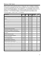
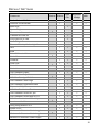
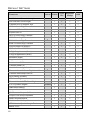
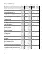
DEFAULT SETTINGS
Many functions of the scanner can be "configured", that is enabled or disabled.
The scanner is shipped from the factory configured to a set of default conditions.
All factory default parameters have an asterisk ( * ) in the default column of the
charts on the following pages . If an asterisk is not in the default column then the
setting is off or disabled by default. Every interface does not support every
parameter. If the interface supports a parameter listed in the charts on the
following pages, a check mark () will appear.
Parameter
Default RS232
Light
Pen
Keyboard
Wedge
USB
Enter Configuration Mode, Only on First
Scan
Short Range Activation
Long Range Activation
Custom Scan
DTR Activation
DC2 Activation
Address Based Activation
“NOREAD” message Transmission
Enter Configuration Mode, After Any Scan
Normal Scan
*
*
*
Turn on Green LED during “NOREAD”
Transmit
*
Same Symbol Re-scan
*
2X Redundancy (MECCA)
Double Border Requirement
(Large Intercharacter Space Requirement)
Alternate Beeper Tone 1
Alternate Beeper Tone 3
No Beeper tone
Two Second Timeout
Green LED Identical Symbol
Re-Scan Indicator
1 Vs 2 Scan Buffers
Alternate Beeper Tone 2
1
*
13
DEFAULT SETTINGS
Parameter
No Two Second Timeout
Default RS232
*
*
*
Beep After Transmit
Baud Rate
Parity
*
RTS/CTS
Character RTS/CTS
9600
Space
8 Data Bits
7 Data Bits
*
Message RTS/CTS
ACK/NAK
XON/XOFF
USB
Three Beeps on Timeout
Beep Before Transmit
Keyboard
Wedge
Razzberry Tone on Timeout
No Tone on Timeout
Light
Pen
*
No Intercharacter Delay
1 Millisecond Intercharacter Delay
5 Millisecond Intercharacter Delay
STX Prefix
ETX Suffix
Tab Prefix
Tab Suffix
10 Millisecond Intercharacter Delay
25 Millisecond Intercharacter Delay
100 Millisecond Intercharacter Delay
DTR Input
DTR Scan Disable
“DE” Disable Command
LRC Calc+ Transmit RS232
Start LRC on first RS232 Byte
Start LRC on Second RS232 Byte
Carriage Return
Line Feed
14
*
*
*
DEFAULT SETTINGS
Parameter
Default RS232
Light
Pen
Keyboard
Wedge
USB
Prefix ID for UPC/EAN
Suffix ID for UPC/EAN
Bars High
*
Spaces High
Transmit as Scanned
*
Transmit as code 39
Poll Light Pen 5 volts
No Poll Light Pen
*
Reverse Polarity Idle for Light Pen
Full ASCII code 39
Code 39
Codabar
Code 128
UPC
EAN
*
*
*
*
*
Code 11
GS1 DataBar Enable
GS1 DataBar ID “]e0”
GS1 DataBar Expanded Enable
Expanded ID “]e0”
GS1 DataBar Limited Enable
GS1 DataBar Limited ID “]e0”
Code 93
GS1 DataBar App ID “01”
GS1 DataBar Check Digit
GS1 DataBar Limited App ID “01”
GS1 DataBar Limited Check Digit
*
*
*
*
*
*
*
*
Hong Kong Matrix 2 of 5
Airline 2 of 5
Minimum 1 Character Code Length
Interleaved 2 of 5
Minimum 3 Character Code Length
Minimum 6 character Code Length
*
15
DEFAULT SETTINGS
Parameter
Default RS232
Light
Pen
Keyboard
Wedge
USB
Set Minimum Character Length
Set Character Lock Length
Transmit UPC-A Number Sys
UPC-A Check Digit Transmit
*
*
Convert UPC-A to EAN-13
Expand UPC-E
UPC-E Check Digit Transmit
UPC-E Leading 0 Transmit
EAN-8 Check Digit Transmit
EAN-13 Check Digit Transmit
Convert EAN-8 to EAN-13
“$” Prefix ID for UPC/EAN
2 Digit Supplements (Scan)
5 Digit Supplements (Scan)
Bookland (Scan)
Supplement Required
Bookland to ISNB
Transmit ISBN CD
Mod 43 Check digit-Code 39
*
Transmit Start/Stop-Code 39
CLSI Editing (Enable)
ITF Check Digit
Transmit Mod 43 Check Digit Code 39
*
Transmit Mod 10 ITF Check Digit
2 of 5 Symbol Lengths
Variable
ISBN Reformatting
Coupon Code 128
]C1 Transmit Coupon C128
Coupon 128 Group Separator
Italian Pharmaceutical
Codabar Start & Stop Class
ITF Minimum Symbol Length Test
Matrix 2 of 5
16
DEFAULT SETTINGS
Parameter
Default RS232
Light
Pen
Keyboard
Wedge
USB
Matrix 2 of 5 Check Digit
Hong Kong Matrix 2 of 5
MSI-Plessy Test of Check Digit
*
Enable MSI-Plessy Mod 10 Check Digit
Enable MSI-Plessy Mod 10/10
Check Digit
UK Plessy
UK Plessey Check Digit
UK Plessey Special Format
A to X conversion (UK)
Scan Count Test Mode
Scanability Test Mode
Normal Scan/Operating Test Mode
Transmit MSI-Plessy Check Digit
*
Default to ScanPal Communication
parameters Code ID
Code ID
Sanyo 635 ECR Protocol
Post Software ID characters
“Newcode” Mode A
“Newcode” Mode B
SNI Beetle Mode
BIO DATA Mode
Enable Sineko Mode
Enable Caps Lock Mode
(for MI951 external wedge)
Rochford Thompson Mode
RTS Counter Toggle
Beep on BEL RS232
17
DEFAULT SETTINGS
Parameter
Default RS232
Light
Pen
Keyboard
Wedge
USB
Retransmit of Same Code
1st Configurable Prefix ID
2nd Configurable Prefix ID
1st Configurable Suffix ID
2nd Configurable Suffix ID
Clear all Configurable Prefixes and
Suffixes
SNI Beetle Mode
AT Keyboard
*
Type XT Keyboard
Type PS2 Keyboard
USA Keyboard
*
Belgium Keyboard
France Keyboard
Germany Keyboard
Spain Keyboard
Italy Keyboard
UK Keyboard
IBM KDB4700 Financial Keyboard
Alt Mode
Auto Detection or Caps Lock
User-Defined Caps Lock
F0H Break Code Transmission
800 Microsecond Delay-Enter Scan Code
*
*
15 Millisecond Delay-Enter Scan Code
7-5 Millisecond delay-Enter Scan Code
18
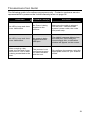
TROUBLESHOOTING GUIDE
The following guide is for reference purposes only. Contact a customer service
representative to preserve the limited warranty terms on page 24.
SYMPTOMS
POSSIBLE CAUSE(S)
SOLUTION
No LEDs, beep and there
is no visible laser
No Power is being
supplied to the
scanner
Make sure the cable is plugged
into the host. Check the host
system’s power cable, the outlet
and power strip.
No LEDs, beep and there
is no visible laser
No power is being
supplied from the
USB port.
The IS4225 requests 100mA from
the USB port. If the USB port
cannot supply this, a notification
window will appear on the screen.
After scanning a bar
code, the Red and Green
LEDs are on, but no data
is being transmitted to the
host.
The scanner is not
configured properly
for communication
with the host.
Re-configure the scanner using the
appropriate codes for your scanner
model.
19
REGULATORY COMPLIANCE
Safety
ITE Equipment
IEC 60950-1, EN 60950-1
Laser
Laser Class 2: IEC 60825-1:1993+A1:1997+A2:2001
EN 60825-1:1994+A2:2001+A1:2002
Caution
Use of controls or adjustments or performance of procedures other than those specified
herein may result in hazardous laser light exposure. Under no circumstances should the
customer attempt to service the laser scanner. Never attempt to look at the laser beam,
even if the scanner appears to be nonfunctional. Never open the scanner in an attempt to
look into the device. Doing so could result in hazardous laser light exposure. The use of
optical instruments with the laser equipment will increase eye hazard.
Atención
La modificación de los procedimientos, o la utilización de controles o ajustes distintos de
los especificados aquí, pueden provocar una luz de láser peligrosa. Bajo ninguna
circunstancia el usuario deberá realizar el mantenimiento del láser del escáner. Ni intentar
mirar al haz del láser incluso cuando este no esté operativo. Tampoco deberá abrir el
escáner para examinar el aparato. El hacerlo puede conllevar una exposición peligrosa a
la luz de láser. El uso de instrumentos ópticos con el equipo láser puede incrementar el
riesgo para la vista.
Attention
L'emploi de commandes, réglages ou procédés autres que ceux décrits ici peut entraîner
de graves irradiations. Le client ne doit en aucun cas essayer d'entretenir lui-même le
scanner ou le laser. Ne regardez jamais directement le rayon laser, même si vous croyez
que le scanner est inactif. N'ouvrez jamais le scanner pour regarder dans l'appareil. Ce
faisant, vous vous exposez à une rayonnement laser qú êst hazardous. L'emploi
d'appareils optiques avec cet équipement laser augmente le risque d'endommagement de
la vision.
Achtung
Die Verwendung anderer als der hier beschriebenen Steuerungen, Einstellungen oder
Verfahren kann eine gefährliche Laserstrahlung hervorrufen. Der Kunde sollte unter keinen
Umständen versuchen, den Laser-Scanner selbst zu warten. Sehen Sie niemals in den
Laserstrahl, selbst wenn Sie glauben, daß der Scanner nicht aktiv ist. Öffnen Sie niemals
den Scanner, um in das Gerät hineinzusehen. Wenn Sie dies tun, können Sie sich einer
gefährlichen Laserstrahlung aussetzen. Der Einsatz optischer Geräte mit dieser
Laserausrüstung erhöht das Risiko einer Sehschädigung.
Attenzione
L’utilizzo di sistemi di controllo, di regolazioni o di procedimenti diversi da quelli descritti nel
presente Manuale può provocare delle esposizioni a raggi laser rischiose. Il cliente non
deve assolutamente tentare di riparare egli stesso lo scanner laser. Non guardate mai il
raggio laser, anche se credete che lo scanner non sia attivo. Non aprite mai lo scanner per
guardare dentro l’apparecchio. Facendolo potete esporVi ad una esposizione laser
rischiosa. L’uso di apparecchi ottici, equipaggiati con raggi laser, aumenta il rischio di
danni alla vista..
20
REGULATORY COMPLIANCE
EMC
Emissions
FCC Part 15, ICES-003, CISPR 22, EN 55022
Immunity
CISPR 24, EN 55024
Changes or modifications not expressly approved by the party responsible for
compliance could void the user’s authority to operate the equipment.
Class A Devices
The following is applicable when the scanner cable is greater in length than 3 meters
(9.8 feet) when fully extended:
Les instructions ci-dessous s’appliquent aux cables de scanner dépassant 3 métres
(9.8 pieds) de long en extension maximale:
Folgendes trifft zu, wenn das Scannerkabel länger als 3 Meter ist:
This equipment has been tested and found to comply with limits for a Class A digital device,
pursuant to part 15 of the FCC Rules. These limits are designed to provide reasonable
protection against harmful interference when the equipment is operated in a commercial
environment. This equipment generates, uses and can radiate radio frequency energy and,
if not installed and used in accordance with the instruction manual, may cause harmful
interference to radio communications. Operation of this equipment in a residential area is
likely to cause harmful interference, in which case the user will be required to correct the
interference at their own expense. Any unauthorized changes or modifications to this
equipment could void the user’s authority to operate this device.
This device complies with part 15 of the FCC Rules. Operation is subject to the following
two conditions: (1) This device may not cause harmful interference, and (2) this device must
accept any interference received, including interference that may cause undesired
operation.
Notice
This Class A digital apparatus complies with Canadian ICES-003.
Remarque
Cet appareil numérique de classe A est conforme à la norme canadienne NMB-003.
European Standard
Warning
This is a class A product. In a domestic environment this product may cause radio
interference in which case the user may be required to take adequate measures.
Funkstöreigenschaften nach EN55022:1998
Warnung!
Dies ist eine Einrichtung der Klasse A. Diese Einrichtung kann im Wohnbereich
Funkstörungen verursachen. In diesem Fall kann vom Betreiber verlangt werden,
angemessene Massnahmen durchzuführen.
Standard Europeo
Attenzione
Questo e’ un prodotto di classe A. Se usato in vicinanza di residenze private potrebbe
causare interferenze radio che potrebbero richiedere all’utilizzatore opportune misure.
Attention
Ce produit est de classe “A”. Dans un environnement domestique, ce produit peut être
la cause d’interférences radio. Dans ce cas l’utiliseteur peut être amené à predre les
mesures adéquates.
21
REGULATORY COMPLIANCE
EMC
Changes or modifications not expressly approved by the party responsible for
compliance could void the user’s authority to operate the equipment.
Class B Devices
The following is applicable when the scanner cable is less than 3 meters
(9.8 feet) in length when fully extended:
Les instructions ci-dessous s’appliquent aux cables de scanner ne dépassant
pas 3 métres (9.8 pieds) de long en extension maximale:
Folgendes trifft zu, wenn das Scannerkabel kürzer als 3 Meter ist:
This device complies with Part 15 of the FCC Rules. Operation is subject to the
following two conditions: (1) This device may not cause harmful interference, and (2)
this device must accept any interference received, including interference that may
cause undesired operation.
This equipment has been tested and found to comply with the limits for a Class B
digital device, pursuant to Part 15 of the FCC rules. These limits are designed to
provide reasonable protection against harmful interference in a residential installation.
This equipment generates, uses and can radiate radio frequency energy and, if not
installed and used in accordance with the instructions, may cause harmful interference
to radio communications. However, there is no guarantee that interference will not
occur in a particular installation. If this equipment does cause harmful interference to
radio or television reception, which can be determined by turning the equipment off
and on, the user is encouraged to try to correct the interference by one or more of the
following measures:
• Reorient or relocate the receiving antenna
• Increase the separation between the equipment and receiver
• Connect the equipment into an outlet on a circuit different from that to which
the receiver is connected
• Consult the dealer or an experienced radio/TV technician for help
Notice
This Class B digital apparatus complies with Canadian ICES-003.
Remarque
Cet appareil numérique de classe B est conforme à la norme canadienne NMB-003.
22
PATENTS
For patent information, please refer to www.honeywellaidc.com/patents.
23
LIMITED WARRANTY
Honeywell International Inc. ("HII") warrants its products and optional accessories to be free
from defects in materials and workmanship and to conform to HII’s published specifications
applicable to the products purchased at the time of shipment. This warranty does not cover
any HII product which is (i) improperly installed or used; (ii) damaged by accident or
negligence, including failure to follow the proper maintenance, service, and cleaning
schedule; or (iii) damaged as a result of (A) modification or alteration by the purchaser or
other party, (B) excessive voltage or current supplied to or drawn from the interface
connections, (C) static electricity or electro-static discharge, (D) operation under conditions
beyond the specified operating parameters, or (E) repair or service of the product by
anyone other than HII or its authorized representatives.
This warranty shall extend from the time of shipment for the duration published by HII for
the product at the time of purchase ("Warranty Period"). Any defective product must be
returned (at purchaser’s expense) during the Warranty Period to HII factory or authorized
service center for inspection. No product will be accepted by HII without a Return Materials
Authorization, which may be obtained by contacting HII. In the event that the product is
returned to HII or its authorized service center within the Warranty Period and HII
determines to its satisfaction that the product is defective due to defects in materials or
workmanship, HII, at its sole option, will either repair or replace the product without charge,
except for return shipping to HII.
EXCEPT AS MAY BE OTHERWISE PROVIDED BY APPLICABLE LAW, THE
FOREGOING WARRANTY IS IN LIEU OF ALL OTHER COVENANTS OR WARRANTIES,
EITHER EXPRESSED OR IMPLIED, ORAL OR WRITTEN, INCLUDING, WITHOUT
LIMITATION, ANY IMPLIED WARRANTIES OF MERCHANTABILITY OR FITNESS FOR A
PARTICULAR PURPOSE, OR NON-INFRINGEMENT.
HII’S RESPONSIBILITY AND PURCHASER’S EXCLUSIVE REMEDY UNDER THIS
WARRANTY IS LIMITED TO THE REPAIR OR REPLACEMENT OF THE DEFECTIVE
PRODUCT WITH NEW OR REFURBISHED PARTS. IN NO EVENT SHALL HII BE
LIABLE FOR INDIRECT, INCIDENTAL, OR CONSEQUENTIAL DAMAGES, AND, IN NO
EVENT, SHALL ANY LIABILITY OF HII ARISING IN CONNECTION WITH ANY PRODUCT
SOLD HEREUNDER (WHETHER SUCH LIABILITY ARISES FROM A CLAIM BASED ON
CONTRACT, WARRANTY, TORT, OR OTHERWISE) EXCEED THE ACTUAL AMOUNT
PAID TO HII FOR THE PRODUCT. THESE LIMITATIONS ON LIABILITY SHALL REMAIN
IN FULL FORCE AND EFFECT EVEN WHEN HII MAY HAVE BEEN ADVISED OF THE
POSSIBILITY OF SUCH INJURIES, LOSSES, OR DAMAGES. SOME STATES,
PROVINCES, OR COUNTRIES DO NOT ALLOW THE EXCLUSION OR LIMITATIONS OF
INCIDENTAL OR CONSEQUENTIAL DAMAGES, SO THE ABOVE LIMITATION OR
EXCLUSION MAY NOT APPLY TO YOU.
All provisions of this Limited Warranty are separate and severable, which means that if any
provision is held invalid and unenforceable, such determination shall not affect the validity
of enforceability of the other provisions hereof. Use of any peripherals not provided by the
manufacturer may result in damage not covered by this warranty. This includes but is not
limited to: cables, power supplies, cradles, and docking stations. HII extends these
warranties only to the first end-users of the products. These warranties are nontransferable.
The duration of the limited warranty for the IS4225 is two (2) year(s). The accessories have
a 90 day limited warranty from the date of manufacture.
24
INDEX
A
I
application .....................................1
audible.......................................5–6
autodiscriminates.........................12
immunity...................................... 21
indicators............................. 5–6, 12
input voltage................................ 12
installation ..................................... 1
interfaces ...................................... 1
B
bar code ................ 4, 5–6, 8, 10, 19
beep ........................ 5–6, 12, 13, 19
C
cable....................................1, 4, 12
caution.....................................7, 20
CDRH ......................................7, 12
class ............................................22
communication ...... 1, 4, 5–6, 13–18
compliance ............................20, 21
configuration guide ....................1, 6
contrast........................................12
current .........................................12
customer service .....................1, 24
D
DC transformer............................12
decode capability.........................12
default....................................13–18
dimensions ..................................12
K
keyboard wedge.......... 1, 12, 13–18
L
labels............................................. 7
laser ............................................ 20
LED..................... 4, 5–6, 10, 12, 19
light levels ................................... 12
light pen emulation ...... 1, 12, 13–18
light source.................................. 12
long range activation ......... 1, 10, 13
M
maintenance ................................. 8
mechanical.................................. 12
min bar width............................... 12
model number ............................... 7
N
E
notices......................................... 22
electrical ......................................12
EMC ............................................21
EMI ..............................................21
emissions ....................................21
environmental..............................12
O
F
operating current ......................... 12
operating temperature................. 12
operation ............................... 12, 22
operational .................................. 12
output window ................... 4, 5–6, 8
function........................................13
P
G
parameter.............................. 13–18
parts.............................................. 4
patents ........................................ 23
PC..................................... 1, 12, 16
power ............................ 5–6, 10, 12
print contrast ............................... 12
protocols ............................... 13–18
good read ....................................12
green LED .............................4, 5–6
H
host ............................. 4, 10, 13–18
humidity .......................................12
25
INDEX
R
T
razzberry tone .........................6, 13
red LED .................................4, 5–6
repair ...........................................24
RMA ............................................24
roll, pitch, yaw..............................12
RS232 ............................. 12, 13–18
temperature................................. 12
termination .................................. 12
test .............................................. 16
test code ..................................... 19
tones ....................................... 6, 12
troubleshooting ........................... 19
S
U
safety.....................................20, 22
scan field ............................. 5–6, 10
scan pattern.................................12
scan speed ..............................1, 12
serial number.................................7
shock ...........................................12
short range activation ........ 1, 10, 13
software.......................................19
specifications...........................4, 12
stand........................................1, 12
storage ........................................12
system interfaces.....................1, 12
USB ...................................... 13–18
26
V
ventilation.................................... 12
visual......................................... 5–6
W
warranty ...................................... 24
Watts........................................... 12
weight.......................................... 12
window ........................ 4, 5–6, 8, 10
CUSTOMER SUPPORT
Technical Assistance
If you need assistance installing or troubleshooting your device, please call your
distributor or the nearest technical support office:
North America/Canada
Telephone: (800) 782-4263
E-mail: [email protected]
Latin America
Telephone: (803) 835-8000
Telephone: (800) 782-4263
E-mail: [email protected]
Brazil
Telephone: +55 (21) 3535-9100
Fax: +55 (21) 3535-9105
E-mail: [email protected]
Mexico
Telephone: (803) 835-8000
E-mail: [email protected]
Europe, Middle East, and Africa
Telephone: +31 (0) 40 7999 393
Fax: +31 (0) 40 2425 672
E-mail: [email protected]
Hong Kong
Telephone: +852-29536436
Fax: +851-2511-3557
E-mail: [email protected]
Singapore
Telephone: +65-6842-7155
Fax: +65-6842-7166
E-mail: [email protected]
China
Telephone: +86 800 828 2803
Fax: +86-512-6762-2560
E-mail: [email protected]
Japan
Telephone: +81-3-3839-8511
Fax: +81-3-3839-8519
E-mail: [email protected]
Online Technical Assistance
You can also access technical assistance online at www.honeywellaidc.com.
27
CUSTOMER SUPPORT
Product Service and Repair
Honeywell International Inc. provides service for all its products through service
centers throughout the world. To obtain warranty or non-warranty service,
contact the appropriate location below to obtain a Return Material Authorization
number (RMA #) before returning the product.
North America
Telephone: (800) 782-4263
E-mail: [email protected]
Latin America
Telephone: (803) 835-8000
Telephone: (800) 782-4263
Fax: (239) 263-9689
E-mail: [email protected]
Brazil
Telephone: +55 (21) 3535-9100
Fax: +55 (21) 3535-9105
E-mail: [email protected]
Mexico
Telephone: +52 (55) 5203-2100
Fax: +52 (55) 5531-3672
E-mail: [email protected]
Europe, Middle East, and Africa
Telephone: +31 (0) 40 2901 633
Fax: +31 (0) 40 2901 631
E-mail: [email protected]
Hong Kong
Telephone: +852-29536436
Fax: +851-2511-3557
E-mail: [email protected]
Singapore
Telephone: +65-6842-7155
Fax: +65-6842-7166
E-mail: [email protected]
China
Telephone: +86 800 828 2803
Fax: +86-512-6762-2560
E-mail: [email protected]
Japan
Telephone: +81-3-3839-8511
Fax: +81-3-3839-8519
E-mail: [email protected]
Online Product Service and Repair Assistance
You can also access product service and repair assistance online at
www.honeywellaidc.com.
28
Honeywell Scanning & Mobility
9680 Old Bailes Road
Fort Mill, SC 29707
www.honeywellaidc.com
00-02258 Rev E
May 2010