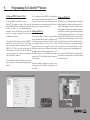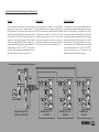
1
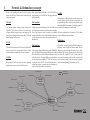
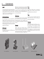
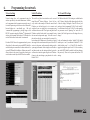
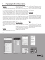
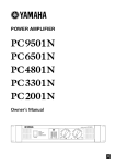
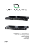
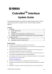
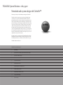
YAMAHA System Solutions white paper
Networked audio system design with CobraNet™
This white paper’s subject is Networked audio system design with CobraNet™.
The design concept in this paper supports systems varying from small touring
event setups to very large scale networked audio installations. That does not
mean that the design concept is the best solution to all system specifications, other
network topologies and audio protocols should always be considered in the initial
phase of the design project. The advantage of this Yamaha System Solutions design
concept is that it is based on Ethernet / CobraNet™, both open protocols that use
computer networking components widely available on the market. Other compatible brands of both network and audio equipment can be included in the design
concept, assuring maximum flexibility and project efficiency for system integrators.
It is also good to know that the design concept is not just a theoretical exercise; we
have built, tested and installed systems based on this design concept so you can be
confident that the concept will work in real life.
We assume the reader is a system integrator with detailed knowledge of analogue
and digital audio, and basic knowledge of networking technologies as covered in
the ‘Yamaha System Solutions - an introduction to networked audio’ white paper.
The Yamaha Commercial Audio team.
CobraNet™ networked audio systems
1. System design
2.
Specification list for Yamaha System Solutions CobraNet™ designs
3.
Network & redundancy concept
4.
Control network
5.
Locations & Connections
6. Programming the network
7.
Programming the IP over Ethernet devices
8.
Yamaha CobraNet™ devices
9.
Programming the CobraNet™ devices
10.
Testing & troubleshooting
11.
System examples
The complete package
1. System design
Customer’s requirements
Design options
Design tools
The first step in any design is to chart the customer’s
requirements. Sometimes the requirements can be found in
a formal tender if a consultant has already been involved
in the customer’s system specification process. In many
cases the consultant or system integrator has to discuss
the customer’s requirements in depth to find the most
appropriate system specifications, and perhaps suggest
additional system possibilities made possible by new
technologies on the market.
Based on the system specifications document, basic design
options can be conceived. The main decision to make is
the selection of the technology to be used: analogue or
digital, point to point or networked, closed (proprietary)
or open (manufacturer-independent) platforms etc. These
decisions are fundamental as they determine the degree of
freedom allowed in further design stages.
The more complex a system the more important design
tools become. A small system can be described in words or
an excel sheet, but larger or more complex systems have to
be described in drawings to be able to communicate them
to all stakeholders in a project. In these cases software
programs are used to construct system designs, such as
AutoCAD in the contracting business, StarDraw in the
audio markets and CobraCAD for CobraNet™ system
designs.
System specifications
After the technology platforms have been selected the
system’s actual network and audio devices must be
selected. Input parameters for selection include feature
set, audio quality, technical reliability, supplier reliability,
complexity and of course cost level. There are no products
with an ‘A-score’ on all of these parameters; quality comes
with higher costs, more functionality comes with a more
complex user interface, etc. The designer must study each
system component’s feature set in depth to assess if it meets
the system specifications or not, and conceive creative
solutions in case no matching products are available.
The second step is to draw up a system specification based
on the customer’s requirements. A system specification
document contains the requirements for a system to fulfill
as operational parameters. The system specifications
should not include any direction to actual solutions as that
would narrow the scope of possibilities in the design stage.
Only by keeping the system specifications and the design
solution options strictly separated can the broad scope of
choices be truly considered by the designer, allowing for
maximum flexibility, quality and creativity in the design
stage.
Selection of network and audio devices
System test
A very important part of the network design process
is to conduct (sub) system tests. Especially network
systems using managed switches offer an extremely high
functionality level that require system tests to verify that
all parameters have been programmed correctly.
Training & after sales
A networked audio system offers different functionality
compared to analogue systems. Therefore the design of
appropriate after sales and training activities for future
users of the system is an important part of the design
stage.
2. Specification list for Yamaha System Solutions CobraNet™ designs
Based on the customer’s requirements a system
specification must be drawn up. For this white paper a
‘one size fits all’ system specification is listed intended
to cover most of ‘every day’ applications from small
touring sound reinforcement sets to large scale distributed
i/o installations. Although this system specification list
will most probably produce a system design that meets
the average customer’s requirements, it might cover
more than required. To achieve efficient system designs
it is recommended to carefully go through the first step
of the system design process of charting the customer’s
requirements before drawing up the system specification
list.
True Network
The design concept should cover virtually all application
sizes; from simple P2P connections to large scale
installations with many locations. To allow this level
of scalability, and to keep systems manageable, a true
network protocol should be used. Functional connections
must be separate from the physical cabling in the network
assuming the network offers sufficient bandwidth for the
application.
Open system
Cabling
Latency
The design concept should cover long distance cabling of The network should support a fixed latency of 1.3 ms for
up to 500 meters. The network design should support up mid size systems. For larger systems higher fixed latency
to five long distance locations. The long distance locations modes are allowed.
should offer connectivity to Local network structures.
Touring
Acoustic noise
Apart from the star location the network devices in the
For live touring applications, touring grade cabling should system should not make any significant audible noise.
be used. Cables should include road proof connectivity
systems.
Status monitoring and control
Topology
For all designs, the network topology should offer easy
connectivity - supporting the use of cost effective computer
networking hardware.
Redundancy
The design concept should include a computer to control
and monitor the system’s audio and network devices.
Serial connectivity
Connectivity of serial standards such as RS232C and
RS422 should be possible using inexpensive hardware.
All designs should feature full redundancy for all network Ethernet connectivity
components. A system should recover automatically from
any network component failure.
The system should offer a 100Mb Ethernet network for
connections to Ethernet compatible devices. This network
Bandwidth
should be separate from the audio network.
Both the network protocol and the audio network protocol
The network should have a bandwidth supporting at least Costs
should be open market standards. This way the new
500 audio channels. All individual audio devices should
developments in the IT industry over the past decades
support up to 64 channel bi-directional links.
The system should be cost effective.
can be utilized, and connectivity is not limited to Yamaha
components alone. The use of established standardised
Options
technology allows high quality and cost-effective designs. Audio quality
The system should support at least 24-bit 48 kHz audio The system should support optional video connections
signals.
using IP cameras, Uninterrupted Power Supplies and
wireless access points etc.
3. Network & Redundancy concept
Based on the system specification list in the previous Both switches support IEEE802.1q VLAN, IEEE802.1w Cabling
chapter the following Yamaha System Solutions design rapid spanning tree, IEEE802.3ad link aggregation and
concept is proposed.
QoS functionality.
All long distance cabling from the star to the four locations
carrying Gigabit network information is specified with
50 µm multimode fiber, connected to the switches using
Network
Star locations
appropriate GBIC fiber modules. For distances under 50
The Yamaha System Solutions design concept uses A high capacity switch including at least four GBIC ports meters CAT5E cabling can be used instead.
CobraNet™ audio devices. All devices are connected to for Gigabit fiber connectivity is used for the star location.
a Gigabit Ethernet network using a star topology. The Such a high capacity switch is typically not available All further connections in the system use CAT5 cabling
network uses managed switches supporting VLAN and without cooling fans, so this location should be planned in carrying 100Mb network information.
Rapid Spanning Tree Protocols.
a place where acoustic noise is not a problem such as the
amplifier rack.
Redundancy
VLAN
End locations
The network is divided in two VLANs: one for CobraNet™
and one for control. If a system requires the use of many A low capacity switch including at least eight 100Mb RJ45
multicast bundles, additional VLANs can be included.
ports, one Gigabit RJ45 port and one GBIC port for Gigabit
fiber connectivity is used for all other locations at the ends
of the star network. The eight 100Mb ports are divided in
Switches
six ports carrying the CobraNet™ VLAN, and two ports
A high capacity and a low capacity switch supporting carrying the control VLAN. The switch should not have
cooling fans so it can be used in noise-free conditions on
Gigabit connectivity are used to build the network.
stage or at the FOH position in the audience.
All locations use double switches, labelled primary and
secondary, with a Gigabit link between them. The two
switches are connected to the star location by two cables,
preferably laid out over different physical paths through
the venue. All CobraNet™ devices’ primary links are
connected to the primary switch, and the secondary links
to the secondary switch. In the star location’s secondary
switch the Rapid Spanning Tree Protocol is active.
Primary link
Cobranet™ device
Cobranet™ device
Secondary link
Cobranet™ device
Ethernet device
Cobranet™ device
Ethernet device
End location
Cobranet™ device
Ethernet device
End location
End location
Cobranet™ device
Cobranet™ device
Star location
Cobranet™ device
End location
Ethernet device
Cobranet™ device
Ethernet device
Cobranet™ device
4. Control network
VLAN
To ensure that CobraNet™ data traffic and other Ethernet
traffic flowing through the network can not interfere with
each other, a separate ‘control’ VLAN is used for all nonCobraNet™ devices. At each switch location two ports are
configured to carry the control VLAN signals.
M7CL Studio Manager
The control VLAN can be used to connect M7CL Studio
Manager to all M7CL consoles in the system. This way the
system engineer can plug in the Ethernet port of a laptop
anywhere in the system and have control over any console.
The Studio Manager software and the consoles are linked
together by their IP addresses.
GPI and parameter control signals in systems using multiple DMX
DME units can be linked together through the control
VLAN. Any DME unit can be monitored, controlled and Using RS485 to Ethernet devices, the connection of
programmed on a computer using DME designer software lighting consoles and dimmer packs using the DMX
from anywhere in the system. Individual DME’s can be control standard can be run on the network.
selected by their IP address.
Wi-Fi
Serial servers
A wireless access point can be added to the control VLAN
A pair of serial servers can be used to connect serial signals to allow wireless access to all of the audio system’s
such as the RS422 head amp control on digital mixers. networked control functionality.
Functional connection is done by matching the serial
server’s IP addresses, allowing multiple serial connections IT network
to be used.
IP cameras
DME Designer
Inexpensive internet video surveillance cameras can
be used to make multiple low quality video monitor
The control VLAN also connects to the Ethernet port on connections to be picked up anywhere in the network. An
internet browser such as Microsoft® Internet Explorer can
all Digital Mixing Engines.
be used to display the video signals on a computer screen.
Serial server (B&B ESP901)
IP camera ( Dlink DCS6620)
Both the complete Yamaha System Solutions network or
just its control VLAN can be connected to an existing
IT network, allowing a venue’s Ethernet devices such
as printers, servers and internet modems to be used.
For these applications, it is essential to involve suitably
experienced network professionals, such as the IT network
administrator.
Wireless access point (Dlink DWL7200)
Lighting console (WholeHog® III)
5. Locations & connections
Locations
Star location
All locations in the system feature two Gigabit managed A high capacity switch, such as the Dlink DGS3324SR, switches. CobraNet™ and Ethernet devices are connected featuring 24 Gigabit ports with four GBIC SFP slots for
to specific connectors of the switches.
fiber connectivity, is used for the star location. Ports 1 to
8 are allocated to VLAN1: default (the control VLAN).
Ports 9 to 16 are allocated to VLAN2: CobraNet™. For
Installations
redundancy one CAT5E patch cable connects to port 17 of
For installations, the network connections of the switches both switches. Ports 21 to 24 double with the GBIC slots
for connection to the end locations.
can be used. No front panel connectors are required.
For touring applications, each location to be connected to
Touring
the star requires two connectors on the front panel of the
® connectors for redundant
In case of a 19” rack, the two top units carry the two location’s case: two EtherCon ®
switches. The back side allows access to the switch CAT5E cabling or two Fiberfox EBC52 connectors for
ports, the front side includes touring connectivity using redundant fiber cabling.
EtherCon® connectors for CAT5E cabling and Fiberfox®
End locations
EBC52 connectors for fiber cabling.
In case of a mixing console, the switches, EtherCon® A low capacity switch, such as the Dlink DES-3010GA,
and Fiberfox® connectors can be built into the mixer’s featuring eight 100Mb ports, one Gigabit port and one
GBIC SFP slot for fiber connectivity, is used for all end
flightcase, e.g. in the dog box at the rear of the console.
locations. This switch does not have a fan so it is silent; it
can be used in critical acoustic environments.
Rack contents
Rack contents
Star location rack front view
End location rack front view
Rack contents
Rack contents
Star location rack rear view
End location rack rear view
Ports 1 and 2 are allocated to VLAN1: default (the control
VLAN). Ports 3 to 8 are allocated to VLAN2: CobraNet.
For locations with Fiber connectivity, one CAT5E patch
cable connects the TX Gigabit ports of both switches to
support the RSTP redundancy, while the GBIC slot is
used for connection with the star location. For locations
with CAT5E connectivity the GBIC slot is used for the
RSTP redundancy link, and the TX Gigabit port for the
connection with the star location.
For touring applications, two connectors are available on
the front panels: two EtherCon® connectors for redundant
CAT5E cabling or two Fiberfox® EBC52 connectors for
redundant fiber cabling. An end location can connect to
further CobraNet™ devices, other than those built in the
stage rack, using two EtherCon® connectors per device.
Redundancy
All connections come in pairs for redundancy. Connections
should be rolled out physically separated from each other
as much as possible to offer maximum protection from
cabling accidents e.g. involving rodents or heavy military
equipment.
Location functional diagram
6. Programming the network
Network settings
Switch IP address
VLAN and STP settings
Network settings have to be programmed using the
software provided by the switch manufacturer. Switches
can be programmed with a computer connected to one of
its network ports using a web browser such as Microsoft®
Internet Explorer in a user-friendly way. Old style
‘command line’ programming is possible using a serial
RS232C connection using the Windows® Hyperterminal
software; the Command Line Interface (CLI) that has to be
used will be described in the switch’s users manual.
The switch’s web based user interface can be accessed
using Microsoft® Internet Explorer. Out of the box,
every switch in this example will have the same default
IP address, so the first thing to do is to connect each
switch one by one as a single device to a computer using
an Ethernet crossover cable. Then log in using the default
IP address specified in the switch’s users manual, leaving
the user name and password empty. To be able to access
the switches after they are connected in the network, it’s
best to change the IP addresses of all switches to a logical
order range on the control network that you will use for IP
services in the system, and document the addresses in the
system project document. After setting the new IP address
and subnet mask store the settings and then log into the
web based user interface again using the new IP address.
Connect to the switch using a port planned to be in the
Default VLAN.
For Dlink switches the VLAN settings are available under
the ‘L2 features’ tab in the folder hierarchy on the left side
of the web display. Clicking the ‘Static VLAN entry’ tab produces a list of programmed VLANs. Use the ‘modify’
or ‘add’ buttons to set up the VLANs. To set the spanning
tree parameters access ‘Spanning Tree’ under the ‘L2
features’ tab. Don’t forget to store all settings after every
change !
Port-based VLAN’s have to be programmed one by one on
all switches. On the secondary star switch RSTP should be
enabled on the ports connected to the other switches in the
system. RSTP should be disabled on all other ports and all
other switches in the system. Connect the secondary star
switch to the network only after RSTP has been enabled.
In the end locations the switches’ default VLAN should
include ports 1 and 2, an additional CobraNet™ VLAN
should include ports 3 to 8. Both VLANs should be
tagged and assigned to ports 9 and 10. On the secondary
star switch RSTP should be enabled on the long distance
link ports only. Then test the system and fine-tune STP
settings.
DES3010G web interface - IP settings
DES3010 CLI interface - IP settings
DGS3324SR web interface - STP settings
DES3010G web interface - VLAN settings 7. Programming the IP over Ethernet devices
Serial server
Cameras can be used for visual communication links,
monitoring of amplifier racks, etc.
To connect RS232C, RS422 and RS485 control signals Using, for example, the Level1 FCS-1030, login to each
over the network a serial server must be used. Serial camera in the system using the default IP address and
servers are available from Moxa, B&B Electronics, Axis change the IP addresses one by one to a logical order range
etc. Using, for example, the B&B ESP901 serial server so they can be accessed later on when the system has been
a web interface is available to program the settings. First assembled. That’s it ! The video signal can be monitored
login using the default IP address of each device in the using a web browser, typing in the IP address in the web
system and change the IP addresses one by one to a logical browser’s URL area. The typical video quality of a budget
order range so they can be accessed later on when the IP camera is MPEG4 VGA with a latency of roughly one
system has been assembled. The serial server allows for its second. For better quality video and lower latency, higher
serial port to be connected to another server by selecting quality cameras or video servers can be specified.
the matching IP address and setting the correct serial port
parameters. For AD8HR head amp control select RS422 at DME Designer software
38,400 baud, 8 data bits, one stop bit, no parity. A special
cable is required to connect the serial server’s port to the To connect a PC to Yamaha devices in a network the
AD8HR.
Yamaha DME network driver needs to be installed first.
For DME designer the network driver’s settings must
include the master DME’s IP address and MAC address to
IP Cameras
allow DME designer to access the network.
IP cameras are available from Dlink, Level1, Sony, Sweex
etc.
ESP901 web interface
IP camera web interface
In the DME designer MIDI Setup menu the network can
be selected as the software’s communication port. Now the
software’s synchronisation menu will display all DMEs
and ICPs in the network.
GPI using DME
At the moment there is no separate GPI network connection
function available in DME designer, so GPI connections
can be made using dummy parameters in each DME unit;
connecting them using the global parameter link function.
M7CL
To connect the M7CL editor to an M7CL mixing console
in the network the DME network driver must be used. Set
matching IP and MAC addresses in the network driver and
the M7CL’s network settings.
DME network driver settings
DME GPI settings
DME network settings
M7CL network settings
8. Yamaha CobraNet™ devices
NHB32-C
DME Satellite
MY16-CII
The NHB32-C is a 32 channel AES/EBU network hub and
interface to CobraNet™. The back panel offers four 25-pin
Dsub connectors for 8 channels / 4 pairs AES/EBU inputs
and outputs each. In 5.3 ms and 2.6 ms latency mode the
NHB32-C supports 4 CobraNet™ bundles in and out, with
a programmable matrix router between the AES/EBU i/o
and CobraNet™ bundles. In 1.3 ms latency mode there is
a restriction of using four bundles in total for inputs and
outputs.
The DME Satellite series are compact 1U units with 8
channels of analogue i/o, 8 GPI inputs and 4 GPI outputs. The DME satellite is available in three analogue i/o
configurations: 4 in 4 out, 8 in or 8 out. All analogue inputs
offer a remote controllable head amp for easy connectivity
of microphone level signals. A serial port is available for
remote control of AD8HR units or RS232C control by
AMX™ or Crestron® systems (for example).
The MY16-CII is the successor of the MY16-C with
connectivity to all MY16 compatible products. The power
supply limitation is solved so the card can be used in any
MY16 compatible digital mixing console. The setting of
bundle numbers with rotary switches has been replaced
by software control using the supplied CobraNet Manager
Lite software package.
MY16-C
ACU16-C
The ACU16-C offers sixteen analogue 24-bit 48 kHz
outputs on Euroblock connectors to drive power amps. An
RS485 data connector is included to connect to a series of
PC01N power amplifiers, bridging the connection to other
ACU16-C units in the network. This functionality allows
control, logging and monitoring of all PC01N amplifiers
with a PC connected to the USB port of any ACU16-C or
NHB32-C in the CobraNet™ network.
NHB32-C
The MY16-C offers 2 bundle i.e. 16ch in & 16ch out
CobraNet™ connectivity to compatible MY16 devices
such as the M7CL, DME24N, DME64N, PM5D. Due to
power supply limitations, the use of the MY16-C in the
DM2000 is limited to one card only, and the MY16-C can
not be used in other MY16 compatible products such as
the DM1000, 02R96, 01V96.
DME4io-C
DME24N, DME64N
Both DME24N and DME64N can connect to a CobraNet™
network using MY16-C or MY16-CII cards.
Digital mixing consoles
Any Yamaha MY16 compatible digital mixing console
can connect to a CobraNet™ network using the MY16-CII
card. The PM5D and M7CL also accept MY16-C cards.
MY16-C
MY16-CII
DME8i-C
ACU16-C
DME8o-C
Digital mixer with Mini-YGDAI slot
DME24N/DME64N with M-YGDAI slot
9. Programming the CobraNet™ devices
Setting up NHB32-C and ACU16-C
In 1.33 ms latency mode the NHB32-C can only handle a Setting up MY16-CII
total of 4 bundles, in all other modes the full 4 in 4 out can
To program NHB32-C and ACU16-C devices a be used. In 5.3 ms latency mode the 24-bit setting reduces The MY16-CII uses a software program to set the bundle
Windows® XP computer is required. First install the the channel count to seven channels per bundle, the lower numbers, sample size, wordclock and latency mode. First
Yamaha MIDI USB driver and NetworkAmp Manager latency modes do not have this restriction.
install Cobranet Manager Lite on the PC, then connect it
software available on www.yamahaproaudio.com/
to the CobraNet™ network. After starting the software, all
downloads. Activate the MIDI ports in the MIDI USB Setting up MY16-C
CobraNet™ devices will be recognized by the program and
driver in the computer’s control panel and launch the
a selection display will ask for four devices to be selected
AmpManager.exe software.
The old version MY16-C cards offers two input bundles for editing. All CobraNet™ devices in the network will be
and two output bundles for a total of 16 channels in and displayed on the CobraNetManager’s screen in a matrix
Then set the rotary ID switches on the front all NHB32-C out. There are two rotary switches on the back of the card view, with the four selected devices activated for editing .
and ACU16-C devices in the network to a logical order for each bundle which can be set from 0 to 15. If both To be able to edit all devices at the same time an upgrade
from zero upwards. Connect the computer to any of the rotary switches are set to 0, the bundle is inactive. If the to the full version of CobraNet™ manager is required,
NHB32-C or ACU16-C units in the network using the MSB rotary switch is set to 0, the LSB rotary switch defines available by request from www.cobranetmanager.com
USB connector on the front side of the unit. With this the bundle number to be multicast ranging from 1 to 15. If
connection all units in the system can be programmed the MSB is set from 1 to 15, the LSB sets unicast bundles Click on an active MY16-CII and select ‘Yamaha settings’
using the CobraNet™ network.
starting from 272. A list of bundle settings is included in to access the device settings menu to set wordclock, sample
size and latency mode.
the users manual.
The software allows settings of the latency mode, unicast
enable, sample size and incoming and outgoing bundle Settings for wordclock (sample rate), sample size and
numbers.
latency mode are also available as dip switches on the
card’s PCB.
Yamaha NetworkAmp Manager (NHB32-C, ACU16-C) Rotary switches bundle selection (MY16-C)
CobraNetManager lite (MY16-CII, DME Satellite)
10. Testing & troubleshooting
Checklist
Check 3: Double check audio settings
Check 6: Sabotage
After assembling a networked audio system it is good
practice to conduct a systematic series of checks to make
sure everything is OK. These checks should include
network functionality, audio functionality and sabotage
behavior.
Using the appropriate software, double check the audio
settings in all individual CobraNet™ devices: bundle
numbers, wordclock settings, sample size and latency
mode. Confirm that the conductor is assigned to the
appropriate device.
Check 1: Double check network settings
Check 4: Listen
Sabotage all network components in the system one by
one: remove cables or power down switches, confirm
system recovery, re-connect or power-up, confirm that
the system switches back to a redundant state. Note the
recovery timing at each stage to include in the project
documentation.
Troubleshooting
Connect a PC to the default VLAN and confirm that
all switches are on-line, for example Dlink’s D-View
monitoring software. Double check the VLAN settings
and STP settings in every individual switch by browsing
them one by one.
Connect some small speakers to the most important
system outputs and then connect an audio source to every If an emergency occurs in a system the most important
input one-by-one and check if a connection to the outputs thing to do is to wait until the recovery is completed.
is available with good sound quality.
Interfering with the system before recovery takes place
might disable the recovery! After the system has recovered
Check 5: Disco
steps 1, 2 and 5 of the checklist can be performed to assess
Check 2: Check the CobraNet™ network
the situation. If the problem can be located wait for a break
Connect a PC to the CobraNet™ network and launch in the performance to solve it as the audio will probably
Connect a PC to the CobraNet™ VLAN and launch Discovery to confirm that all audio connections are really be affected when the system switches back to a redundant
state.
CobraNet™ Manager. Confirm that all CobraNet™ devices error-free. Check for errors at all bundles.
are shown in the overview.
CobraNet™ Discovery
D-View 5.1
CobraNet™ Manager
11. System examples
M7CL FOH & monitor locations, stage amplifier rack, two 24ch input racks
System
CobraNet™
IP over Ethernet
As the system star location includes high capacity switches
with fans it is located in the amp rack - set up in a place
where the amp’s fan noise is not a problem. One mixing
console is located on the FOH position, one on the Monitor
position side stage. Two 24 channel input racks are set on
stage, with 8 returns each for local monitoring. Double
(redundant) EtherCon® cabling is used for the long
distance links.
Each stage rack transmits three multicast bundles to be
picked up anywhere on the network. From FOH and MON
mixers unicast bundles are sent to the amplifier rack and
the two stagerack return outputs. A third mixer, recording
rack or a clean feed to an OB van can be added to the
system at any time at any location.
The control network is used to connect the RS422 head
amp control signals from the FOH M7CL mixer to the
first stage rack, and from the first stagerack to the second
using serial servers. A laptop is connected to the FOH
location (or any other location), allowing access to both
FOH and monitor mixers, the DME output devices in both
stageracks and the IP cameras in the amplifier rack, FOH
mixer and Monitor mixer locations.
Rev
6 * Ethercon panel
8 + 2 switch
UTP
EtherCon
Gigabit SFP 25
TX 1
UTP
EtherCon
Gigabit TX
TX 2
UTP
EtherCon
UTP
EtherCon
UTP
EtherCon
UTP
EtherCon
digital mixing console
PRI
SEC
TX 3
PRI
SEC
MY16-C
MY16-C
8 + 2 switch
6 * Ethercon panel
Slot 1
EtherCon
Gigabit SFP 25
TX 1
CobraNet Primary
EtherCon
Gigabit TX
TX 2
CobraNet Secundary
UTP
EtherCon
UTP
EtherCon
UTP
EtherCon
UTP
EtherCon
USB
AES/EBU out A
RS-422 HA Remote
AES/EBU out B
TX 3
PRI
SEC
MY16-C
RS422 / PC
AES/EBU B
I/P 3
AES/EBU C
I/P 4
TX 6
TX 7
Neu trik Ethercon
AES/EBU D
Omni O/P 1
MAINS I/P
I/P Ch 2
Omni O/P 2
DES-3010G
I/P Ch 3
Omni O/P 3
I/P Ch 1
I/P 2
TX 5
RS-232C
Slot 3
TX 7
TX 8
DES-3010G
I/P 5
TX 8
D-link
I/P 6
I/P 7
I/P 8
Omni O/P 4
I/P Ch 4
TX 1
I/P Ch 6
TX 2
I/P Ch 7
TX 3
I/P Ch 8
TX 4
I/P Ch 9
Word Clock In
Omni O/P 5
I/P Ch 5
8 + 2 switch
Gigabit SFP 25
Gigabit TX
Gigabit SFP 25
TX 1
Gigabit TX
TX 2
Omni O/P 8
TX 6
TX 7
TX 5
TX 7
I/P Ch 12
Omni O/P 12
TX 8
I/P Ch 13
Omni O/P 13
MAINS I/P
Omni O/P 14
DES-3010G
I/P Ch 14
I/P Ch 15
Omni O/P 15 Left
I/P Ch 16
Omni O/P 16 Right
Word Clock Out
MIDI Out
MAINS I/P
MAINS I/P
YAMAHA AD8HR
YAMAHA NHB32-C
TX 8
serial server
D-link
Netw ork
RS-422
A/D convertor
AES/EBU out B
RS422 HA remote
2TR O/P Digital
I/P 1
I/P Ch 19
RS-422
4
AES/EBU out A
I/P Ch 17
I/P Ch 18
serial server
Netw ork
3
03-03-06 first
03-03-06 stud
netw
XLR
TX 4
Omni O/P 10
Omni O/P 11
RS-232C
MAINS I/P
Word Clock In
MIDI In
TX 3
Omni O/P 9
I/P Ch 10
I/P Ch 11
DES-3010G
Word Clock Out
8 + 2 switch
Omni O/P 6
Omni O/P 7
TX 5
TX 6
RS-232C
D-link
1
2
I/P 1
TX 4
AES/EBU A
TX 5
TX 6
MAINS I/P
D-link
RS422 HA remote
COM
Slot 2
TX 4
RS-232C
Neu trik Ethercon
A/D convertor
AES/EBU hub bridge
UTP
UTP
Date
12V DC
Lamp
RS422 / PC
I/P 2
B&B ESP901
I/P Ch 20
Lamp
I/P 3
23-03-06 Wire
2*I
I/P Ch 21
I/P 4
I/P Ch 22
serial server
I/P Ch 23
Netw ork
I/P 5
RS-422
I/P 6
I/P Ch 24
12V DC
I/P 7
B&B ESP901
I/P Ch 25
I/P 8
I/P Ch 26
I/P Ch 27
IP camera
Word Clock In
I/P Ch 28
12V DC
I/P Ch 29
B&B ESP901
Word Clock Out
UTP
I/P Ch 30
Amp Control Unit
I/P Ch 31
USB
CobraNet Primary
I/P Ch 32
CobraNet Secundary
COM
2 Channel Amplifier
O/P 1
I/P A
O/P A
Gigabit SFP 25
TX 1
Gigabit FSP 26
TX 2
MAINS I/P
YAMAHA AD8HR
I/P Ch 33
24+4 switch
RS485 PC/N control
I/P Ch 34
9V DC
O/P 2
Bridge
I/P Ch 35
O/P 3
O/P 4
I/P B
O/P 5
Data Port 1
O/P B
Gigabit FSP 27
TX 3
Gigabit FSP 28
TX 4
Level1 FCS 1030
I/P Ch 36
I/P Ch 37
Digital Mixing Engine
O/P 6
Data Port 2
O/P 7
O/P 8
MAINS I/P
TX 5
Yamaha
PC9501N
TX 6
Laptop
TX 7
O/P 9
I/P Ch 38
CobraNet Primary
I/P Ch 39
CobraNet Secundary
O/P 12
2 Channel Amplifier
TX 9
I/P Ch 42
TX 10
I/P Ch 43
O/P A
TX 11
I/P Ch 44
Bridge
TX 12
I/P Ch 45
I/P A
9V DC
I/P B
O/P B
Son y V AIO Z50 0 TEK
I/P 3
I/P 4
O/P 5
I/P 5
O/P 6
I/P 6
O/P 7
I/P 7
I/P Ch 47
TX 14
O/P 8
MAINS I/P
YAMAHA ACU16-C
O/P 3
O/P 4
I/P Ch 46
TX 13
Word Clock Out
Data Port 1
I/P 1
I/P 2
RS422 / PC
O/P 15
Word Clock In
Data Port 2
MAINS I/P
ST I/P Left 1
TX 16
RS-232C
I/P 8
I/P Ch 48
TX 15
Yamaha
PC9501N
AES/EBU out A
AES/EBU out B
RS422 HA remote
O/P 14
O/P 16
O/P 1
O/P 2
I/P Ch 41
TX 8
O/P 13
A/D convertor
Netw ork
RS-422 HA Remote
I/P Ch 40
NIC
O/P 10
O/P 11
GPI in 1
GPI out 1
ST I/P Right 1
GPI in 2
GPI in 3
GPI out 3
ST I/P Left 2
GPI in 4
GPI out 4
ST I/P Right 2
GPI in 5
TX 17
TX 18
Word Clock In
Word Clock Out
GPI out 2
GPI in 6
TX 19
2 Channel Amplifier
I/P A
TX 20
O/P A
Bridge
6 * Ethercon panel
TX 21
UTP
TX 22
UTP
EtherCon
TX 23
UTP
EtherCon
ST I/P Left 3
GPI in 7
ST I/P Right 3
GPI in8
ST I/P Right 4
MAINS I/P
YAMAHA DME8o-C
Word Clock In
I/P B
O/P B
MAINS I/P
TX 24
UTP
EtherCon
DGS-3324SR
UTP
EtherCon
MAINS I/P
D-link
Yamaha
PC9501N
24+4 switch
2 Channel Amplifier
I/P A
O/P A
Gigabit SFP 25
TX 1
Gigabit FSP 26
TX 2
Bridge
Gigabit FSP 27
TX 3
O/P B
Gigabit FSP 28
TX 4
I/P B
Data Port 1
TX 5
Data Port 2
TX 6
MAINS I/P
Yamaha
PC9501N
UTP
EtherCon
UTP
EtherCon
UTP
EtherCon
Neu trik Ethercon
YAMAHA AD8HR
Midi Out
RS422 Remote
FOH mixer
MAINS I/P
Word Clock Out
Midi In
Data Port 1
Data Port 2
Symbols Used
ST I/P Left 4
EtherCon
Netw ork
DC Power I/P
Yamaha
M7CL-48 MB
stage rack 24 input 8 output
TX 7
TX 8
TX 9
TX 10
2 Channel Amplifier
I/P A
TX 11
O/P A
TX 12
Bridge
TX 13
O/P B
TX 14
UTP
EtherCon
TX 15
I/P B
6 * Ethercon panel
8 + 2 switch
Gigabit SFP 25
TX 1
Gigabit TX
TX 2
digital mixing console
PRI
SEC
Data Port 1
Data Port 2
MAINS I/P
Yamaha
PC9501N
UTP
EtherCon
TX 16
UTP
EtherCon
TX 17
UTP
EtherCon
TX 18
UTP
EtherCon
TX 19
UTP
EtherCon
TX 3
MY16-C
6 * Ethercon panel
UTP
EtherCon
UTP
EtherCon
UTP
EtherCon
UTP
EtherCon
UTP
EtherCon
UTP
EtherCon
8 + 2 switch
TX 1
CobraNet Primary
Gigabit TX
TX 2
CobraNet Secundary
USB
TX 20
2 Channel Amplifier
TX 21
O/P A
TX 22
Bridge
TX 23
PRI
SEC
MY16-C
I/P 1
TX 7
MAINS I/P
D-link
TX 8
DES-3010G
RS422 / PC
I/P 2
TX 5
AES/EBU B
I/P 3
AES/EBU C
I/P 4
TX 6
TX 7
Neu trik Ethercon
AES/EBU D
Omni O/P 1
MAINS I/P
I/P Ch 2
Omni O/P 2
DES-3010G
I/P Ch 3
Omni O/P 3
I/P Ch 1
RS422 HA remote
COM
TX 4
RS-232C
Slot 3
TX 6
Neu trik Ethercon
AES/EBU out A
AES/EBU out B
RS-422 HA Remote
TX 3
Slot 2
AES/EBU A
TX 5
A/D convertor
AES/EBU hub bridge
Gigabit SFP 25
Slot 1
MY16-C
TX 4
RS-232C
I/P A
PRI
SEC
RS-232C
I/P 5
TX 8
D-link
I/P 6
I/P 7
I/P 8
I/P B
O/P B
Data Port 1
MAINS I/P
D-link
MAINS I/P
I/P Ch 4
TX 24
DGS-3324SR
Data Port 2
8 + 2 switch
I/P Ch 5
Gigabit SFP 25
TX 1
I/P Ch 6
Gigabit TX
TX 2
I/P Ch 7
Omni O/P 4
Word Clock In
Omni O/P 6
Word Clock In
8 + 2 switch
I/P Ch 8
I/P Ch 9
MIDI In
Word Clock Out
MIDI Out
TX 1
Omni O/P 7
Gigabit TX
TX 3
TX 4
Word Clock Out
Omni O/P 5
Gigabit SFP 25
Yamaha
PC9501N
TX 2
Omni O/P 8
TX 3
Omni O/P 9
TX 4
IP camera
UTP
TX 5
I/P Ch 10
Omni O/P 10
TX 6
I/P Ch 11
Omni O/P 11
MAINS I/P
RS-232C
2 Channel Amplifier
TX 5
RS-232C
MAINS I/P
YAMAHA AD8HR
YAMAHA NHB32-C
TX 6
I/P A
O/P A
TX 7
I/P Ch 12
TX 8
I/P Ch 13
Omni O/P 12
TX 7
Bridge
I/P B
MAINS I/P
D-link
O/P B
DES-3010G
Data Port 1
Omni O/P 13
MAINS I/P
I/P Ch 14
Omni O/P 14
I/P Ch 15
Omni O/P 15 Left
I/P Ch 16
Omni O/P 16 Right
TX 8
D-link
DES-3010G
MAINS I/P
Yamaha
PC9501N
Client
A/D convertor
AES/EBU out A
9V DC
Data Port 2
AES/EBU out B
Level1 FCS 1030
I/P Ch 17
IP camera
RS422 HA remote
I/P Ch 18
I/P 1
2TR O/P Digital
UTP
I/P Ch 19
Lamp
RS422 / PC
serial server
Netw ork
I/P 2
RS-422
I/P Ch 20
I/P 3
Lamp
2 Channel Amplifier
I/P A
I/P Ch 21
YMC
I/P 4
I/P Ch 22
O/P A
I/P 5
I/P Ch 23
Bridge
I/P 6
9V DC
I/P B
I/P Ch 24
O/P B
Level1 FCS 1030
Data Port 1
I/P Ch 25
I/P 8
B&B ESP901
I/P Ch 26
Data Port 2
MAINS I/P
I/P 7
12V DC
Word Clock In
Yamaha
PC9501N
Word Clock Out
I/P Ch 27
I/P Ch 28
Amplifier rack - system star
I/P Ch 29
I/P Ch 30
I/P Ch 31
MAINS I/P
YAMAHA AD8HR
I/P Ch 32
I/P Ch 33
I/P Ch 34
I/P Ch 35
I/P Ch 36
Digital Mixing Engine
I/P Ch 37
CobraNet Primary
I/P Ch 38
CobraNet Secundary
A/D convertor
AES/EBU out A
Netw ork
RS-422 HA Remote
AES/EBU out B
I/P Ch 39
RS422 HA remote
O/P 1
I/P 1
I/P Ch 40
RS422 / PC
O/P 2
I/P 2
O/P 3
I/P 3
I/P Ch 41
I/P Ch 42
O/P 4
I/P 4
O/P 5
I/P 5
I/P Ch 43
I/P Ch 44
O/P 6
I/P 6
O/P 7
I/P 7
O/P 8
I/P 8
Title
Messe
I/P Ch 45
I/P Ch 46
I/P Ch 47
I/P Ch 48
GPI in 1
ST I/P Left 1
ST I/P Right 1
GPI out 1
GPI in 2
GPI out 2
GPI in 3
GPI out 3
GPI in 4
GPI out 4
Word Clock In
Word Clock Out
GPI in 5
ST I/P Left 2
GPI in 6
ST I/P Right 2
GPI in 7
GPI in8
ST I/P Left 3
ST I/P Right 3
MAINS I/P
YAMAHA DME8o-C
ST I/P Left 4
ST I/P Right 4
Word Clock In
Midi In
MAINS I/P
YAMAHA AD8HR
Word Clock Out
Midi Out
RS422 Remote
Netw ork
MON mixer
DC Power I/P
Yamaha
M7CL-48 MB
stage rack 24 input 8 output
Yamaha Sys
Cobranet au
4-location boardroom with analogue I/O and control
System
CobraNet™
IP over Ethernet
All four rooms offer connectivity to four analogue stereo
player/recorder devices such as compact cassette, CD,
DVD, Minidisk etc. Two faders and on/off switches with
tally LED are provided in all four rooms for simple control
of the audio level. Further GPI inputs and outputs are
available to control external equipment. More detailed
control of the audio functionality can be realized using a
computer with DME designer user control displays on a
computer display. Crestron® or AMX™ Control systems
can also be used, integrating other multimedia devices in
the system such as video recorders, projectors etc.
Each room features one DME8i-C and one DME8o-C
device offering 8 inputs and 8 outputs in all rooms. Each
DME8i-C unit transmits one multicast bundle so all inputs
of all rooms are available in any location. For ad-hoc
expansion a mixing console or extra i/o devices can be
connected to any switch in the system, e.g. when two or
more rooms are combined for a company presentation an
01V96 mixing console can be used to mix the event.
A computer can be used to control the DME units in the
system with user friendly control menus on the computer’s
display. GPI functionality of each DME device in the
system can be linked to all other DME devices for detailed
control of the complete system functionality. Each room is
fitted with an IP camera offering simple and cost effective
video links between rooms using computers connected to
the control network. As the DME designer software offers
easy interfacing functions for Crestron® and AMX™
systems, the audio system can be integrated in total
multimedia systems based on these platforms.
Digital Mixing Engine
CobraNet Primary
CobraNet Secundary
24+4 switch
Gigabit SFP 25
TX 1
Gigabit FSP 26
TX 2
Gigabit FSP 27
TX 3
Gigabit FSP 28
TX 4
Network
RS-422 HA Remote
I/P 1
I/P 2
TX 5
I/P 3
TX 6
I/P 4
TX 7
I/P 5
TX 8
I/P 6
TX 9
I/P 7
TX 10
I/P 8
TX 11
IP camera
UTP
TX 12
GPI in 1
GPI out 1
GPI in 2
GPI out 2
GPI in 3
GPI out 3
GPI in 4
GPI out 4
TX 13
TX 14
9V DC
GPI in 5
TX 15
GPI in 6
GPI in 7
8 + 2 switch
6 * Ethercon panel
Level1 FCS1030
UTP
EtherCon
Gigabit SFP 25
TX 1
UTP
EtherCon
Gigabit TX
TX 2
Digital Mixing Engine
CobraNet Primary
RS-232C
YAMAHA DME8i-C
CobraNet Secundary
UTP
EtherCon
TX 3
UTP
EtherCon
TX 4
UTP
EtherCon
TX 5
EtherCon
EtherCon
UTP
EtherCon
TX 24
UTP
EtherCon
TX 22
UTP
EtherCon
UTP
EtherCon
UTP
EtherCon
O/P 3
UTP
EtherCon
O/P 4
UTP
EtherCon
O/P 5
TX 3
TX 4
UTP
EtherCon
TX 5
UTP
EtherCon
DGS-3324SR
24+4 switch
O/P 6
Gigabit SFP 25
TX 1
O/P 7
Gigabit FSP 26
TX 2
O/P 8
Gigabit FSP 27
TX 3
Gigabit FSP 28
TX 4
EtherCon
Gigabit SFP 25
TX 1
EtherCon
Gigabit TX
TX 2
TX 1
Gigabit TX
TX 2
GPI out 2
GPI in 3
GPI out 3
GPI in 4
GPI out 4
UTP
EtherCon
Digital Mixing Engine
CobraNet Primary
CobraNet Secundary
Network
RS-422 HA Remote
GPI in 1
GPI out 1
GPI in 2
GPI out 2
TX 6
I/P 4
TX 7
I/P 5
MAINS I/P
TX 8
D-link
I/P 6
I/P 6
DES-3010G
I/P 7
GPI in 3
GPI out 3
GPI in 4
GPI out 4
8 + 2 switch
Gigabit SFP 25
TX 1
Gigabit TX
TX 2
I/P 7
I/P 8
GPI in 1
GPI out 1
GPI in 2
GPI out 2
GPI in 3
GPI out 3
GPI in 4
GPI out 4
8 + 2 switch
GPI in 5
Gigabit SFP 25
TX 1
Gigabit TX
TX 2
GPI in8
TX 4
TX 5
MAINS I/P
TX 5
YAMAHA DME8i-C
RS-232C
MAINS I/P
YAMAHA DME8i-C
RS-232C
TX 6
TX 7
GPI out 3
GPI out 4
GPI in 7
GPI in8
YAMAHA DME8i-C
GPI out 1
GPI out 2
GPI in 3
GPI in 4
GPI in 6
TX 3
GPI in 7
TX 4
MAINS I/P
GPI in 1
GPI in 2
GPI in 5
GPI in 6
TX 3
GPI in 7
RS-232C
I/P 3
RS-232C
Neutrik Ethercon
I/P 5
GPI in8
GPI out 1
GPI in 2
TX 5
I/P 8
GPI in 5
TX 3
TX 4
EtherCon
I/P 4
DES-3010G
GPI in 6
Neutrik Ethercon
TX 3
EtherCon
TX 8
D-link
I/P 7
I/P 8
Gigabit SFP 25
EtherCon
UTP
I/P 2
TX 7
MAINS I/P
I/P 6
8 + 2 switch
UTP
UTP
I/P 1
TX 6
Neutrik Ethercon
I/P 5
TX 6
GPI controller
GPI in 1
UTP
UTP
I/P 3
RS-232C
I/P 4
TX 8
TX 5
GPI out 2
8 + 2 switch
6 * Ethercon panel
Network
RS-422 HA Remote
I/P 2
TX 4
GPI o u t 1
Digital Mixing Engine
CobraNet Primary
CobraNet Secundary
I/P 1
TX 7
DES-3010G
YAMAHA CP4SF
TX 6
TX 7
TX 7
TX 5
MAINS I/P
MAINS I/P
TX 8
D-link
TX 6
GPI in 5
MAINS I/P
TX 8
D-link
DES-3010G
TX 7
GPI in 6
TX 8
D-link
DES-3010G
Digital Mixing Engine
CobraNet Primary
GPI in 7
YAMAHA CP4SF
TX 2
EtherCon
TX 6
D-link
GPI out 2
GPI i n 1
TX 1
Gigabit TX
EtherCon
UTP
I/P 3
RS-232C
Neutrik Ethercon
MAINS I/P
D-link
O/P 2
O/P 1
GPI o u t 1
6 * Ethercon panel
UTP
UTP
TX 23
TX 21
Network
RS-422 HA Remote
MAINS I/P
GPI i n 1
Gigabit SFP 25
EtherCon
UTP
I/P 2
TX 20
Digital Mixing Engine
GPI controller
EtherCon
UTP
I/P 1
TX 18
TX 19
CobraNet Primary
UTP
TX 17
MAINS I/P
CobraNet Secundary
8 + 2 switch
6 * Ethercon panel
Network
RS-422 HA Remote
TX 16
GPI in8
DES-3010G
Digital Mixing Engine
Network
CobraNet Primary
Digital Mixing Engine
Network
CobraNet Primary
Network
TX 8
GPI in8
CobraNet Secundary
CobraNet Secundary
RS-422 HA Remote
CobraNet Secundary
RS-422 HA Remote
RS-422 HA Remote
TX 9
MAINS I/P
YAMAHA DME8o-C
O/P 1
TX 10
TX 11
TX 12
O/P 2
GPI controller
IP camera
UTP
TX 13
O/P 3
GPI i n 1
O/P 1
O/P 4
GPI o u t 1
O/P 3
GPI i n 1
TX 18
GPI controller
GPI in 1
TX 19
GPI i n 1
TX 20
GPI out 1
GPI in 2
GPI out 2
GPI o u t 1
GPI in 3
GPI out 3
GPI out 2
GPI in 4
GPI out 4
O/P 7
O/P 8
9V DC
GPI controller
Level1 FCS1030
GPI in 1
GPI i n 1
GPI in 5
TX 21
GPI in 6
YAMAHA CP4SF
GPI in8
GPI out 1
GPI in 2
GPI out 2
GPI o u t 1
GPI in 3
GPI out 3
GPI out 2
GPI in 4
GPI out 4
O/P 7
O/P 8
9V DC
GPI controller
Level1 FCS1030
GPI in 1
GPI i n 1
GPI in 5
GPI in8
GPI out 2
GPI in 3
GPI out 3
GPI out 2
GPI in 4
GPI out 4
GPI in 6
GPI in 7
YAMAHA CP4SF
GPI out 1
GPI in 2
GPI o u t 1
GPI in 5
GPI in 6
GPI in 7
TX 22
O/P 6
YAMAHA CP4SF
O/P 7
O/P 8
9V DC
Level1 FCS1030
O/P 5
YAMAHA CP4SF
TX 16
O/P 4
GPI out 2
O/P 6
YAMAHA CP4SF
TX 17
GPI o u t 1
O/P 5
O/P 6
TX 15
RS-232C
O/P 3
GPI i n 1
GPI out 2
O/P 5
TX 14
O/P 2
GPI controller
IP camera
UTP
O/P 4
GPI o u t 1
GPI out 2
O/P 1
O/P 2
GPI controller
IP camera
UTP
GPI in 7
YAMAHA CP4SF
GPI in8
TX 23
MAINS I/P
MAINS I/P
TX 24
D-link
YAMAHA DME8o-C
MAINS I/P
YAMAHA DME8o-C
MAINS I/P
YAMAHA DME8o-C
DGS-3324SR
Large meeting room i/o
& control - system star
Meeting room 1 i/o
& control
Meeting room 2 i/o
& control
Auditorium i/o
& control
Notes
Notes
The complete package
The complete package
Yamaha System solutions
White paper ‘networked audio system design with CobraNet™’
Yamaha’s expanded Commercial Audio portfolio facilitates a single
manufacturer solution to the most complex of audio installation and
touring challenges. We offer digital mixing and processing as well as
multi-channel, networking amplification and a wide range of advanced
output devices.
Although we are proud of our line up of excellent quality products, we
understand that a system solution includes more than just products:
cabling, network technology, design tools, quality management tools
etc. This document aims to support networked audio system design
including examples of 3rd party components.
Yamaha Commercial Audio, 2006 - Ron Bakker, Hiroshi Hamamatsu, Tim
Harrison, Kei Nakayama, Taku Nishikori, Tree Tordoff
AMX™ is a trademark of AMX corporation. Crestron® is a trademark of Crestron Electronics, Inc.
CobraNet™ is a trade mark of Peak Audio, a division of Cirrus Logic. EtherCon® is a trademark of
Neutrik Vertrieb GmbH. Fiberfox® is a trademark of Connex Elektrotechnische Stecksysteme GmbH. WholeHog® is a trademark of High End Systems, Inc. Microsoft® Internet Explorer, Windows® are
trademarks of MicroSoft Corporation.