1
IAR Assembler
Reference Guide
for Renesas
V850 Microcontroller Family
AV850-4
AV850-4
COPYRIGHT NOTICE
Copyright © 1998–2010 IAR Systems AB.
No part of this document may be reproduced without the prior written consent of IAR
Systems AB. The software described in this document is furnished under a license and
may only be used or copied in accordance with the terms of such a license.
DISCLAIMER
The information in this document is subject to change without notice and does not
represent a commitment on any part of IAR Systems. While the information contained
herein is assumed to be accurate, IAR Systems assumes no responsibility for any errors
or omissions.
In no event shall IAR Systems, its employees, its contractors, or the authors of this
document be liable for special, direct, indirect, or consequential damage, losses, costs,
charges, claims, demands, claim for lost profits, fees, or expenses of any nature or kind.
TRADEMARKS
IAR Systems, IAR Embedded Workbench, C-SPY, visualSTATE, From Idea To Target,
IAR KickStart Kit, IAR PowerPac, IAR YellowSuite, IAR Advanced Development Kit,
IAR, and the IAR Systems logotype are trademarks or registered trademarks owned by
IAR Systems AB. J-Link is a trademark licensed to IAR Systems AB.
Microsoft and Windows are registered trademarks of Microsoft Corporation.
Renesas is a registered trademark of Renesas Electronics Corporation. V850 is a
trademark of Renesas Electronics Corporation.
All other product names are trademarks or registered trademarks of their respective
owners.
EDITION NOTICE
Fourth edition: October 2010
Part number: AV850-4
This guide applies to version 3.80 of IAR Embedded Workbench® for V850.
Internal reference: R11, AFE1, IJOA.
AV850-4
Contents
Tables
........................................................................................................................ 7
Preface
...................................................................................................................... 9
Who should read this guide ................................................................. 9
How to use this guide ............................................................................. 9
What this guide contains ....................................................................... 9
Other documentation ........................................................................... 10
Document conventions ........................................................................ 10
Typographic conventions ................................................................... 11
Naming conventions .......................................................................... 11
Introduction to the IAR Assembler for V850
................................... 13
Introduction to assembler programming .................................... 13
Getting started .................................................................................... 13
Modular programming ......................................................................... 14
External interface details .................................................................... 15
Assembler invocation syntax ............................................................. 15
Passing options ................................................................................... 15
Environment variables ....................................................................... 16
Error return codes ............................................................................... 16
Source format .......................................................................................... 17
Assembler instructions ........................................................................ 17
Syntax deviations ............................................................................... 18
Expressions, operands, and operators ........................................... 18
Integer constants ................................................................................ 18
ASCII character constants .................................................................. 19
Floating-point constants ..................................................................... 19
TRUE and FALSE ............................................................................. 20
Symbols .............................................................................................. 20
Labels ................................................................................................. 21
Register symbols ................................................................................ 21
Predefined symbols ............................................................................ 21
3
AV850-4
Absolute and relocatable expressions ................................................ 23
Expression restrictions ....................................................................... 24
List file format .......................................................................................... 25
Header ................................................................................................ 25
Body ................................................................................................... 25
Summary ............................................................................................ 25
Symbol and cross-reference table ...................................................... 25
Programming hints ................................................................................ 26
Accessing special function registers .................................................. 26
Using C-style preprocessor directives ................................................ 26
Assembler options
........................................................................................... 27
Setting command line assembler options ................................... 27
Extended command line file .............................................................. 27
Summary of assembler options ........................................................ 28
Description of assembler options .................................................... 29
Assembler operators
...................................................................................... 41
Precedence of operators ..................................................................... 41
Summary of assembler operators ................................................... 41
Unary operators – 1 ............................................................................ 41
Multiplicative arithmetic operators – 2 .............................................. 42
Additive arithmetic operators – 3 ....................................................... 42
Shift operators – 4 .............................................................................. 42
AND operators – 5 ............................................................................. 42
OR operators – 6 ................................................................................ 43
Comparison operators – 7 .................................................................. 43
Description of operators ..................................................................... 43
Assembler directives ....................................................................................... 55
Summary of assembler directives ................................................... 55
Module control directives ................................................................... 59
Syntax ................................................................................................. 59
Parameters .......................................................................................... 60
Descriptions ....................................................................................... 60
IAR Assembler
4
Reference Guide for V850
AV850-4
Contents
Symbol control directives ................................................................... 62
Syntax ................................................................................................. 62
Parameters .......................................................................................... 63
Descriptions ....................................................................................... 63
Examples ............................................................................................ 64
Segment control directives ................................................................ 65
Syntax ................................................................................................. 65
Parameters .......................................................................................... 66
Descriptions ....................................................................................... 67
Examples ............................................................................................ 68
Value assignment directives .............................................................. 70
Syntax ................................................................................................. 70
Parameters .......................................................................................... 71
Operand modifiers .............................................................................. 71
Descriptions ....................................................................................... 71
Examples ............................................................................................ 72
Conditional assembly directives ....................................................... 75
Syntax ................................................................................................. 75
Parameters ......................................................................................... 75
Descriptions ....................................................................................... 76
Examples ............................................................................................ 76
Macro processing directives ............................................................... 77
Syntax ................................................................................................. 77
Parameters .......................................................................................... 77
Descriptions ....................................................................................... 78
Examples ............................................................................................ 81
Listing control directives ..................................................................... 85
Syntax ................................................................................................. 85
Parameters .......................................................................................... 85
Descriptions ....................................................................................... 86
Examples ............................................................................................ 87
C-style preprocessor directives ........................................................ 89
Syntax ................................................................................................. 89
Parameters .......................................................................................... 90
5
AV850-4
Descriptions ....................................................................................... 90
Examples ............................................................................................ 93
Data definition or allocation directives ......................................... 94
Syntax ................................................................................................. 94
Parameters .......................................................................................... 94
Descriptions ....................................................................................... 94
Examples ............................................................................................ 95
Assembler control directives ............................................................ 96
Syntax ................................................................................................. 96
Parameters .......................................................................................... 96
Descriptions ....................................................................................... 96
Examples ............................................................................................ 97
Function directives ................................................................................. 98
Syntax ................................................................................................. 98
Parameters .......................................................................................... 98
Descriptions ....................................................................................... 99
Call frame information directives ................................................... 99
Syntax ............................................................................................... 100
Parameters ........................................................................................ 102
Descriptions ..................................................................................... 103
Simple rules ...................................................................................... 106
CFI expressions ................................................................................ 108
Example ........................................................................................... 111
Assembler diagnostics
.................................................................................. 115
Message format ..................................................................................... 115
Severity levels ........................................................................................ 115
Options for diagnostics ................................................................... 115
Assembly warning messages ........................................................... 115
Command line error messages ......................................................... 115
Assembly error messages ................................................................. 116
Assembly fatal error messages ......................................................... 116
Assembler internal error messages .................................................. 116
Index
IAR Assembler
6
Reference Guide for V850
AV850-4
..................................................................................................................... 117
Tables
1: Typographic conventions used in this guide ......................................................... 11
2: Naming conventions used in this guide ................................................................ 11
3: Assembler environment variables ......................................................................... 16
4: Assembler error return codes ................................................................................ 16
5: Integer constant formats ........................................................................................ 19
6: ASCII character constant formats ......................................................................... 19
7: Floating-point constants ........................................................................................ 20
8: Predefined register symbols .................................................................................. 21
9: Predefined symbols ............................................................................................... 22
10: Symbol and cross-reference table ....................................................................... 25
11: Assembler options summary ............................................................................... 28
12: Conditional list (-c) ............................................................................................. 30
13: Parameter list (--fpu) ........................................................................................... 31
14: Controlling case sensitivity in user symbols (-s) ................................................ 36
15: Specifying the processor configuration (-v) ........................................................ 37
16: Disabling assembler warnings (-w) ..................................................................... 38
17: Including cross-references in assembler list file (-x) .......................................... 39
18: Assembler directives summary ........................................................................... 55
19: Module control directives ................................................................................... 59
20: Symbol control directives ................................................................................... 62
21: Segment control directives .................................................................................. 65
22: Value assignment directives ................................................................................ 70
23: Operand modifiers ............................................................................................... 71
24: Conditional assembly directives ......................................................................... 75
25: Macro processing directives ................................................................................ 77
26: Listing control directives ..................................................................................... 85
27: C-style preprocessor directives ........................................................................... 89
28: Data definition or allocation directives ............................................................... 94
29: Assembler control directives ............................................................................... 96
30: Call frame information directives ....................................................................... 99
31: Unary operators in CFI expressions .................................................................. 109
7
AV850-4
32: Binary operators in CFI expressions ................................................................. 109
33: Ternary operators in CFI expressions ............................................................... 111
34: Code sample with backtrace rows and columns ............................................... 112
IAR Assembler
8
Reference Guide for V850
AV850-4
Preface
Welcome to the IAR Assembler Reference Guide for V850. The purpose of
this guide is to provide you with detailed reference information that can help
you to use the IAR Assembler for V850 to develop your application according
to your requirements.
Who should read this guide
You should read this guide if you plan to develop an application, or part of an
application, using assembler language for the V850 microcontroller and need to get
detailed reference information on how to use the IAR Assembler for V850. In addition,
you should have working knowledge of the following:
●
The architecture and instruction set of the V850 microcontroller. Refer to the
documentation from Renesas for information about the V850 microcontroller
●
General assembler language programming
●
Application development for embedded systems
●
The operating system of your host computer.
How to use this guide
When you first begin using the IAR Assembler for V850, you should read the chapter
Introduction to the IAR Assembler for V850 in this reference guide.
If you are an intermediate or advanced user, you can focus more on the reference
chapters that follow the introduction.
If you are new to using the IAR Systems toolkit, we recommend that you first read the
initial chapters of the IDE Project Management and Building Guide.
What this guide contains
Below is a brief outline and summary of the chapters in this guide.
●
Introduction to the IAR Assembler for V850 provides programming information. It
also describes the source code format, and the format of assembler listings.
●
Assembler options first explains how to set the assembler options from the
command line and how to use environment variables. It then gives an alphabetical
9
AV850-4
Other documentation
summary of the assembler options, and contains detailed reference information
about each option.
●
Assembler operators gives a summary of the assembler operators, arranged in order
of precedence, and provides detailed reference information about each operator.
●
Assembler directives gives an alphabetical summary of the assembler directives, and
provides detailed reference information about each of the directives, classified into
groups according to their function.
●
Assembler diagnostics contains information about the formats and severity levels of
diagnostic messages.
Other documentation
The complete set of IAR Systems development tools for the V850 microcontroller is
described in a series of guides and online help files. For information about:
●
Using the IAR Embedded Workbench® IDE, refer to the IDE Project Management
and Building Guide
●
Using the IAR C-SPY® Debugger, refer to the C-SPY® Debugging Guide for V850
●
Programming for the IAR C/C++ Compiler for V850, refer to the IAR C/C++
Compiler Reference Guide for V850
●
Using the IAR XLINK Linker, the IAR XAR Library Builder, and the IAR XLIB
Librarian, refer to the IAR Linker and Library Tools Reference Guide
●
Using the IAR DLIB Library, refer to the online help system
●
Porting application code and projects created with a previous IAR Embedded
Workbench IDE for V850, refer to the IAR Embedded Workbench® Migration
Guide for V850.
All of these guides are delivered in hypertext PDF or HTML format on the installation
media. Some of them are also delivered as printed books.
Document conventions
When, in this text, we refer to the programming language C, the text also applies to C++,
unless otherwise stated.
When referring to a directory in your product installation, for example v850\doc, the
full path to the location is assumed, for example c:\Program Files\IAR
Systems\Embedded Workbench 6.n\v850\doc.
IAR Assembler
10
Reference Guide for V850
AV850-4
Preface
TYPOGRAPHIC CONVENTIONS
This guide uses the following typographic conventions:
Style
Used for
computer
• Source code examples and file paths.
• Text on the command line.
• Binary, hexadecimal, and octal numbers.
parameter
A placeholder for an actual value used as a parameter, for example
filename.h where filename represents the name of the file.
[option]
An optional part of a command.
a|b|c
Alternatives in a command.
{a|b|c}
A mandatory part of a command with alternatives.
bold
Names of menus, menu commands, buttons, and dialog boxes that
appear on the screen.
italic
• A cross-reference within this guide or to another guide.
• Emphasis.
…
An ellipsis indicates that the previous item can be repeated an arbitrary
number of times.
Identifies instructions specific to the IAR Embedded Workbench® IDE
interface.
Identifies instructions specific to the command line interface.
Identifies helpful tips and programming hints.
Identifies warnings.
Table 1: Typographic conventions used in this guide
NAMING CONVENTIONS
The following naming conventions are used for the products and tools from IAR
Systems® referred to in this guide:
Brand name
Generic term
IAR Embedded Workbench® for V850
IAR Embedded Workbench®
IAR Embedded Workbench® IDE for V850
the IDE
IAR C-SPY® Debugger for V850
C-SPY, the debugger
IAR C-SPY® Simulator
the simulator
IAR C/C++ Compiler™ for V850
the compiler
Table 2: Naming conventions used in this guide
11
AV850-4
Document conventions
Brand name
Generic term
IAR Assembler™ for V850
the assembler
IAR XLINK™ Linker
XLINK, the linker
IAR XAR Library builder™
the library builder
IAR XLIB Librarian™
the librarian
IAR DLIB Library™
the DLIB library
Table 2: Naming conventions used in this guide (Continued)
IAR Assembler
12
Reference Guide for V850
AV850-4
Introduction to the IAR
Assembler for V850
This chapter contains these sections:
●
Introduction to assembler programming
●
Modular programming
●
External interface details
●
Source format
●
Assembler instructions
●
Expressions, operands, and operators
●
List file format
●
Programming hints.
Introduction to assembler programming
Even if you do not intend to write a complete application in assembler language, there
might be situations where you find it necessary to write parts of the code in assembler,
for example, when using mechanisms in the V850 microcontroller that require precise
timing and special instruction sequences.
To write efficient assembler applications, you should be familiar with the architecture
and instruction set of the V850 microcontroller. Refer to Renesas’ hardware
documentation for syntax descriptions of the instruction mnemonics.
GETTING STARTED
To ease the start of the development of your assembler application, you can:
●
Work through the tutorials—especially the one about mixing C and assembler
modules—that you find in the IAR Information Center
●
Read about the assembler language interface—also useful when mixing C and
assembler modules—in the IAR C/C++ Compiler Reference Guide for V850
13
AV850-4
Modular programming
●
In the IAR Embedded Workbench IDE, you can base a new project on a template
for an assembler project.
Modular programming
It is widely accepted that modular programming is a prominent feature of good software
design. If you structure your code in small modules—in contrast to one single
monolith—you can organize your application code in a logical structure, which makes
the code easier to understand, and which aids:
●
efficient program development
●
reuse of modules
●
maintenance.
The IAR development tools provide different facilities for achieving a modular structure
in your software.
Typically, you write your assembler code in assembler source files. In each source file
you define one or several assembler modules, using the module control directives. Each
module has a name and a type, where the type can be either PROGRAM or LIBRARY. The
linker always includes a PROGRAM module, whereas a LIBRARY module is only included
in the linked code if other modules refer to a public symbol in the module. You can
divide each module further into subroutines.
A segment is a logical entity containing a piece of data or code that should be mapped
to a physical location in memory. Use the segment control directives to place your code
and data in segments. A segment can be either absolute or relocatable. An absolute
segment always has a fixed address in memory, whereas the address for a relocatable
segment is resolved at link time. Segments let you control how your code and data is
placed in memory. Each segment consists of many segment parts. A segment part is the
smallest linkable unit, which allows the linker to include only those units that are
referred to.
If you are working on a large project you will soon accumulate a collection of useful
routines that are used by several of your applications. To avoid ending up with a huge
amount of small object files, collect modules that contain such routines in a library
object file. In the IAR Embedded Workbench IDE, you can set up a library project, to
collect many object files in one library. For an example, see the tutorials in the IAR
Information Center.
To summarize, your software design benefits from modular programming, and to
achieve a modular structure you can:
●
IAR Assembler
14
Reference Guide for V850
AV850-4
Create many small modules, either one per source file, or many modules per file by
using the module directives
Introduction to the IAR Assembler for V850
●
In each module, divide your assembler source code into small subroutines
(corresponding to functions on the C level)
●
Divide your assembler source code into segments, to gain more precise control of
how your code and data finally is placed in memory
●
Collect your routines in libraries, which means that you can reduce the number of
object files and make the modules conditionally linked.
External interface details
This section provides information about how the assembler interacts with its
environment.
You can use the assembler either from the IAR Embedded Workbench IDE or from the
command line. Refer to the IDE Project Management and Building Guide for
information about using the assembler from the IAR Embedded Workbench IDE.
ASSEMBLER INVOCATION SYNTAX
The invocation syntax for the assembler is:
av850 [options][sourcefile][options]
For example, when assembling the source file prog.s85, use this command to generate
an object file with debug information:
av850 prog -r
By default, the IAR Assembler for V850 recognizes the filename extensions s85, asm,
and msa for source files. The default filename extension for assembler output is r85.
Generally, the order of options on the command line, both relative to each other and to
the source filename, is not significant. However, there is one exception: when you use
the -I option, the directories are searched in the same order that they are specified on the
command line.
If you run the assembler from the command line without any arguments, the assembler
version number and all available options including brief descriptions are directed to
stdout and displayed on the screen.
PASSING OPTIONS
You can pass options to the assembler in three different ways:
●
Directly from the command line
Specify the options on the command line after the av850 command; see Assembler
invocation syntax, page 15.
15
AV850-4
External interface details
●
Via environment variables
The assembler automatically appends the value of the environment variables to every
command line; see Environment variables, page 16.
●
Via a text file by using the -f option; see -f, page 31.
For general guidelines for the option syntax, an options summary, and a detailed
description of each option, see the Assembler options chapter.
ENVIRONMENT VARIABLES
Assembler options can also be specified in the ASMV850 environment variable. The
assembler automatically appends the value of this variable to every command line, so it
provides a convenient method of specifying options that are required for every assembly.
You can use these environment variables with the IAR Assembler for V850:
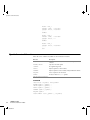
Environment variable
Description
ASMV850
Specifies command line options; for example:
set ASMV850=-L -ws
ASMV850_INC
Specifies directories to search for include files; for example:
set ASMV850_INC=c:\myinc\
Table 3: Assembler environment variables
For example, setting this environment variable always generates a list file with the name
temp.lst:
set ASMV850=-l temp.lst
For information about the environment variables used by the IAR XLINK Linker and
the IAR XLIB Librarian, see the IAR Linker and Library Tools Reference Guide.
ERROR RETURN CODES
When using the IAR Assembler for V850 from within a batch file, you might have to
determine whether the assembly was successful to decide what step to take next. For this
reason, the assembler returns these error return codes:
Return code
Description
0
Assembly successful, warnings might appear.
1
Warnings occurred (only if the -ws option is used).
2
Errors occurred.
Table 4: Assembler error return codes
IAR Assembler
16
Reference Guide for V850
AV850-4
Introduction to the IAR Assembler for V850
Source format
The format of an assembler source line is as follows:
[label [:]] [operation] [operands] [; comment]
where the components are as follows:
label
A definition of a label, which is a symbol that represents an
address. If the label starts in the first column—that is, at the far
left on the line—the :(colon) is optional.
operation
An assembler instruction or directive. This must not start in the
first column—there must be some whitespace to the left of it.
operands
An assembler instruction or directive can have zero, one, two,
three, or four operands. The operands are separated by commas.
An operand can be:
• a constant representing a numeric value or an address
• a symbolic name representing a numeric value or an address
(where the latter also is referred to as a label)
• a floating-point constant
• a register
• a predefined symbol
• the program location counter (PLC)
• an expression.
comment
Comment, preceded by a ; (semicolon)
C or C++ comments are also allowed.
The components are separated by spaces or tabs.
A source line can not exceed 2047 characters.
Tab characters, ASCII 09H, are expanded according to the most common practice; i.e.
to columns 8, 16, 24 etc. This affects the source code output in list files and debug
information. Because tabs might be set up differently in different editors, do not use tabs
in your source files.
Assembler instructions
The IAR Assembler for V850 supports the syntax for assembler instructions as
described in the chip manufacturer’s hardware documentation. It complies with the
requirement of the V850 architecture on word alignment. Any instructions in a code
segment placed on an odd address results in an error.
Note: See also Operand modifiers, page 71.
17
AV850-4
Expressions, operands, and operators
SYNTAX DEVIATIONS
Instructions with a condition code as operand
Assembler instructions with a condition code as operand, for example SETF, have this
format in the Renesas documentation:
SETF
cccc,reg
In the IAR assembler, the condition code is merged with the mnemonic:
SETFNZ reg
instead of
SETF
NZ,reg
PREPARE/DISPOSE
The IAR Assembler for V850 syntax for the PREPARE/DISPOSE instruction does not
follow the syntax described in the Renesas documentation for the imm5 parameter. In
the Renesas description, imm5 has the range 0–31, directly encoded into opcode. For the
IAR assembler, imm5 has the range 0-124 encoded into opcode after division by 4.
Expressions, operands, and operators
Expressions consist of expression operands and operators.
The assembler accepts a wide range of expressions, including both arithmetic and
logical operations. All operators use 32-bit two’s complement integers. Range checking
is performed if a value is used for generating code.
Expressions are evaluated from left to right, unless this order is overridden by the
priority of operators; see also Assembler operators, page 41.
These operands are valid in an expression:
●
Constants for data or addresses, excluding floating-point constants.
●
Symbols—symbolic names—which can represent either data or addresses, where
the latter also is referred to as labels.
●
The program location counter (PLC), $ (dollar).
The operands are described in greater detail on the following pages.
INTEGER CONSTANTS
Because all IAR Systems assemblers use 32-bit two’s complement internal arithmetic,
integers have a (signed) range from -2147483648 to 2147483647.
IAR Assembler
18
Reference Guide for V850
AV850-4
Introduction to the IAR Assembler for V850
Constants are written as a sequence of digits with an optional - (minus) sign in front to
indicate a negative number.
Commas and decimal points are not permitted.
These types of number representation are supported:
Integer type
Example
Binary
1010b, b'1010
Octal
1234q, q'1234
Decimal
1234, -1, d'1234
Hexadecimal
0FFFFh, 0xFFFF, h'FFFF
Table 5: Integer constant formats
Note: Both the prefix and the suffix can be written with either uppercase or lowercase
letters.
ASCII CHARACTER CONSTANTS
ASCII constants can consist of any number of characters enclosed in single or double
quotes. Only printable characters and spaces can be used in ASCII strings. If the quote
character itself will be accessed, two consecutive quotes must be used:
Format
Value
'ABCD'
ABCD (four characters).
"ABCD"
ABCD'\0' (five characters the last ASCII null).
'A''B'
A'B
'A'''
A'
'''' (4 quotes)
'
'' (2 quotes)
Empty string (no value).
"" (2 double quotes)
Empty string (an ASCII null character).
\'
', for quote within a string, as in 'I\'d love to'
\\
\, for \ within a string
\"
", for double quote within a string
Table 6: ASCII character constant formats
FLOATING-POINT CONSTANTS
The IAR Assembler for V850 will accept floating-point values as constants and convert
them into IEEE single-precision (signed 64-bit) floating-point format or fractional
format.
19
AV850-4
Expressions, operands, and operators
Floating-point numbers can be written in the format:
[+|-][digits].[digits][{E|e}[+|-]digits]
This table shows some valid examples:
Format
Value
10.23
1.023 x 101
1.23456E-24
1.23456 x 10⁻²⁴
1.0E3
1.0 x 10³
Table 7: Floating-point constants
Spaces and tabs are not allowed in floating-point constants.
Note: Floating-point constants will not give meaningful results when used in
expressions.
TRUE AND FALSE
In expressions a zero value is considered FALSE, and a non-zero value is considered
TRUE.
Conditional expressions return the value 0 for FALSE and 1 for TRUE.
SYMBOLS
User-defined symbols can be up to 255 characters long, and all characters are
significant. Depending on what kind of operation a symbol is followed by, the symbol
is either a data symbol or an address symbol where the latter is referred to as a label. A
symbol before an instruction is a label and a symbol before, for example the EQU
directive, is a data symbol. A symbol can be:
●
absolute—its value is known by the assembler
●
relocatable—its value is resolved at link time.
Symbols must begin with a letter, a–z or A–Z, ? (question mark), or _ (underscore).
Symbols can include the digits 0–9 and $ (dollar).
Case is insignificant for built-in symbols like instructions, registers, operators, and
directives. For user-defined symbols, case is by default significant but can be turned on
and off using the Case sensitive user symbols (-s) assembler option. See -s, page 36
for additional information.
Use the symbol control directives to control how symbols are shared between modules.
For example, use the PUBLIC directive to make one or more symbols available to other
modules. The EXTERN directive is used for importing an untyped external symbol.
IAR Assembler
20
Reference Guide for V850
AV850-4
Introduction to the IAR Assembler for V850
Note that symbols and labels are byte addresses. For additional information, see
Generating a lookup table, page 95.
LABELS
Symbols used for memory locations are referred to as labels.
Program location counter (PLC)
The assembler keeps track of the start address of the current instruction. This is called
the program location counter.
If you must refer to the program location counter in your assembler source code, use the
$ (dollar) sign. For example:
BR
$
; Loop forever
REGISTER SYMBOLS
This table shows the existing predefined register symbols:
Name
Description
ECT
Floating-point control register*
EFG
Floating-point flag register*
EP
Element pointer, alias for R30
GP
Alias for R4
HP
Alias for R2
LP
Link pointer, alias for R31
PC
Program counter
R0–R31
General purpose registers
SP
Stack pointer, alias for R3
TP
Alias for R5
ZERO
Zero register, alias for R0
VR0–VR31
Vector registers used by SIMD instructions.
This applies only to V850E2M.
Table 8: Predefined register symbols
*
Only available for processors with a floating-point unit.
PREDEFINED SYMBOLS
The IAR Assembler for V850 defines a set of symbols for use in assembler source files.
The symbols provide information about the current assembly, allowing you to test them
21
AV850-4
Expressions, operands, and operators
in preprocessor directives or include them in the assembled code. The strings returned
by the assembler are enclosed in double quotes.
These predefined symbols are available:
Symbol
Value
__AV850__
An integer that is set to 1 when the code is assembled with
the IAR Assembler for V850.
__BUILD_NUMBER__
A unique integer that identifies the build number of the
assembler currently in use. The build number does not
necessarily increase with an assembler that is released later.
__DATE__
The current date in dd/Mmm/yyyy format (string).
__FILE__
The name of the current source file (string).
__IAR_SYSTEMS_ASM__
IAR assembler identifier (number). Note that the number
could be higher in a future version of the product. This
symbol can be tested with #ifdef to detect whether the
code was assembled by an assembler from IAR Systems.
__LINE__
The current source line number (number).
__TID__
Target identity, consisting of two bytes (number). The low
byte is the target identity, which is 0x55 for av850. The
high byte is the processor option *16.
These values are therefore possible:
-v0
0x0055
-v1
0x1055
__SUBVERSION__
An integer that identifies the version letter of the version
number, for example the C in 4.21C, as an ASCII character.
__TIME__
The current time in hh:mm:ss format (string).
__VER__
The version number in integer format; for example, version
4.17 is returned as 417 (number).
Table 9: Predefined symbols
Note: The symbol __TID__ is related to the predefined symbol __TID__ in the IAR
C/C++ Compiler for V850. It is described in the IAR C/C++ Compiler Reference Guide
for V850. There you can also find detailed information about the processor variants and
the -v processor option.
Including symbol values in code
Several data definition directives make it possible to include a symbol value in the code.
These directives define values or reserve memory. To include a symbol value in the code,
use the symbol in the appropriate data definition directive.
IAR Assembler
22
Reference Guide for V850
AV850-4
Introduction to the IAR Assembler for V850
For example, to include the time of assembly as a string for the program to display:
timdat
db
...
movea
jarl
__TIME__,",",__DATE__,0
; time and date
timdat,R0,R6
; Load address of string
printstring,R10 ; routine to print string
Testing symbols for conditional assembly
To test a symbol at assembly time, use one of the conditional assembly directives. These
directives let you control the assembly process at assembly time.
For example, if you want to assemble separate code sections depending on whether you
are using an old assembler version or a new assembler version, do as follows:
#if (__VER__ > 300)
;…
;…
#else
;…
;…
#endif
; New assembler version
; Old assembler version
See Conditional assembly directives, page 75.
ABSOLUTE AND RELOCATABLE EXPRESSIONS
Depending on what operands an expression consists of, the expression is either absolute
or relocatable. Absolute expressions are those expressions that only contain absolute
symbols or relocatable symbols that cancel each other out.
Expressions that include symbols in relocatable segments cannot be resolved at
assembly time, because they depend on the location of segments. These are referred to
as relocatable expressions.
Such expressions are evaluated and resolved at link time, by the IAR XLINK Linker.
There are no restrictions on the expression; any operator can be used on symbols from
any segment, or any combination of segments.
For example, a program could define the segments DATA and CODE as follows:
first
second
third
module
rseg
ds
ds
ds
endmod
data_mod
DATA
5
3
8
module
extern
code_mod
first
23
AV850-4
Expressions, operands, and operators
extern
extern
rseg
mov
mov
mov
mov
end
second
third
CODE
first+7, R10
first-7, R10
7+first, R10
(first/second)*third, R10
Note: At assembly time, there is no range check. The range check occurs at link time
and, if the values are too large, there is a linker error.
EXPRESSION RESTRICTIONS
Expressions can be categorized according to restrictions that apply to some of the
assembler directives. One such example is the expression used in conditional statements
like IF, where the expression must be evaluated at assembly time and therefore cannot
contain any external symbols.
The following expression restrictions are referred to in the description of each directive
they apply to.
No forward
All symbols referred to in the expression must be known, no forward references are
allowed.
No external
No external references in the expression are allowed.
Absolute
The expression must evaluate to an absolute value; a relocatable value (segment offset)
is not allowed.
Fixed
The expression must be fixed, which means that it must not depend on variable-sized
instructions. A variable-sized instruction is an instruction that might vary in size
depending on the numeric value of its operand.
IAR Assembler
24
Reference Guide for V850
AV850-4
Introduction to the IAR Assembler for V850
List file format
The format of an assembler list file is as follows:
HEADER
The header section contains product version information, the date and time when the file
was created, and which options were used.
BODY
The body of the listing contains the following fields of information:
●
The line number in the source file. Lines generated by macros, if listed, have a .
(period) in the source line number field.
●
The address field shows the location in memory, which can be absolute or relative
depending on the type of segment. The notation is hexadecimal.
●
The data field shows the data generated by the source line. The notation is
hexadecimal. Unresolved values are represented by ..... (periods), where two periods
signify one byte. These unresolved values are resolved during the linking process.
●
The assembler source line.
SUMMARY
The end of the file contains a summary of errors and warnings that were generated.
SYMBOL AND CROSS-REFERENCE TABLE
When you specify the Include cross-reference option, or if the LSTXRF+ directive was
included in the source file, a symbol and cross-reference table is produced.
This information is provided for each symbol in the table:
Information
Description
Symbol
The symbol’s user-defined name.
Mode
ABS (Absolute), or REL (Relocatable).
Segments
The name of the segment that this symbol is defined relative to.
Value/Offset
The value (address) of the symbol within the current module, relative to
the beginning of the current segment part.
Table 10: Symbol and cross-reference table
25
AV850-4
Programming hints
Programming hints
This section gives hints on how to write efficient code for the IAR Assembler for V850.
For information about projects including both assembler and C or C++ source files, see
the IAR C/C++ Compiler Reference Guide for V850.
ACCESSING SPECIAL FUNCTION REGISTERS
Specific header files for several V850 devices are included in the IAR Systems product
package, in the \v850\inc directory. These header files define the processor-specific
special function registers (SFRs) and interrupt vectors.
The header files are intended to be used also with the IAR C/C++ Compiler for V850,
and therefore they are made with macros. The macros that convert the declaration to
assembler or compiler syntax are defined in the io_macros.h file.
The header files can also be used as templates, when creating new header files for other
V850 devices.
Example
If any assembler-specific additions are needed in the header file, you can easily add
these in the assembler-specific part of the file:
#ifdef __IAR_SYSTEMS_ASM__
; Add your assembler-specific defines here.
#endif
USING C-STYLE PREPROCESSOR DIRECTIVES
The C-style preprocessor directives are processed before other assembler directives.
Therefore, do not use preprocessor directives in macros and do not mix them with
assembler-style comments. For more information about comments, see Assembler
control directives, page 96.
IAR Assembler
26
Reference Guide for V850
AV850-4
Assembler options
This chapter first explains how to set the options from the command line, and
gives an alphabetical summary of the assembler options. It then provides
detailed reference information for each assembler option.
The IDE Project Management and Building Guide describes how to set assembler
options in the IAR Embedded Workbench® IDE, and gives reference
information about the available options.
Setting command line assembler options
To set assembler options from the command line, include them on the command line,
after the av850 command:
av850 [options] [sourcefile] [options]
These items must be separated by one or more spaces or tab characters.
If all the optional parameters are omitted, the assembler displays a list of available
options a screenful at a time. Press Enter to display the next screenful.
For example, when assembling the source file power2.s85, use this command to
generate a list file to the default filename (power2.lst):
av850 power2 -L
Some options accept a filename, included after the option letter with a separating space.
For example, to generate a list file with the name list.lst:
av850 power2 -l list.lst
Some other options accept a string that is not a filename. This is included after the option
letter, but without a space. For example, to generate a list file to the default filename but
in the subdirectory named list:
av850 power2 -Llist\
Note: The subdirectory you specify must already exist. The trailing backslash is
required to separate the name of the subdirectory and the default filename.
EXTENDED COMMAND LINE FILE
In addition to accepting options and source filenames from the command line, the
assembler can accept them from an extended command line file.
27
AV850-4
Summary of assembler options
By default, extended command line files have the extension xcl, and can be specified
using the -f command line option. For example, to read the command line options from
extend.xcl, enter:
av850 -f extend.xcl
Summary of assembler options
This table summarizes the assembler options available from the command line:
Command line option
Description
-B
Macro execution information
-c
Conditional list
-D
Defines preprocessor symbols
-E
Maximum number of errors
-f
Extends the command line
--fpu
Enables floating-point unit instructions
-G
Opens standard input as source
-I
Add search path for header file
-i
Lists #included text
-L
Generates list file to path
-l
Generates list file
-M
Macro quote characters
-N
Omit header from assembler listing
-n
Enables support for multibyte characters
-O
Sets object filename to path
-o
Sets object filename
-p
Sets the number of lines per page
-r
Generates debug information
-S
Sets silent operation
-s
Case sensitive user symbols
-t
Tab spacing
-U
Undefines a symbol
-v
Specifies the processor core
-w
Disables warnings
Table 11: Assembler options summary
IAR Assembler
28
Reference Guide for V850
AV850-4
Assembler options
Command line option
Description
-x
Includes cross-references
Table 11: Assembler options summary (Continued)
Description of assembler options
The following sections give detailed reference information about each assembler option.
Note that if you use the page Extra Options to specify specific command line options,
there is no check for consistency problems like conflicting options, duplication of
options, or use of irrelevant options.
-B -B
Use this option to make the assembler print macro execution information to the standard
output stream on every call of a macro. The information consists of:
●
The name of the macro
●
The definition of the macro
●
The arguments to the macro
●
The expanded text of the macro.
This option is mainly used in conjunction with the list file options -L or -l; for
additional information, see page 32.
Project>Options>Assembler >List>Macro execution info
-c -c{DSEAOM}
Use this option to control the contents of the assembler list file. This option is mainly
used in conjunction with the list file options -L and -l; see page 32 for additional
information.
29
AV850-4
Description of assembler options
This table shows the available parameters:
Command line option
Description
-cD
Disable list file
-cS
No structured assembler list
-cE
No macro expansions
-cA
Assembled lines only
-cO
Multiline code
-cM
Macro definitions
Table 12: Conditional list (-c)
To set related options, select:
Project>Options>Assembler >List
-D -Dsymbol[=value]
Defines a symbol to be used by the preprocessor with the name symbol and the value
value. If no value is specified, 1 is used.
The -D option allows you to specify a value or choice on the command line instead of
in the source file.
Example
You might want to arrange your source to produce either the test or production version
of your program dependent on whether the symbol TESTVER was defined. To do this use
include sections such as:
#ifdef TESTVER
...
; additional code lines for test version only
#endif
Then select the version required on the command line as follows:
Production version:
Test version:
av850 prog
av850 prog -DTESTVER
Alternatively, your source might use a variable that you must change often. You can then
leave the variable undefined in the source, and use -D to specify the value on the
command line; for example:
av850 prog -DFRAMERATE=3
Project>Options>Assembler>Preprocessor>Defined symbols
IAR Assembler
30
Reference Guide for V850
AV850-4
Assembler options
-E -Enumber
This option specifies the maximum number of errors that the assembler reports.
By default, the maximum number is 100. The -E option allows you to decrease or
increase this number to see more or fewer errors in a single assembly.
Project>Options>Assembler>Diagnostics>Max number of errors
-f -f filename
Extends the command line with text read from the specified file. Notice that there must
be a space between the option itself and the filename.
The -f option is particularly useful if there are many options which are more
conveniently placed in a file than on the command line itself.
Example
To run the assembler with further options taken from the file extend.xcl, use:
av850 prog -f extend.xcl
To set this option, use:
Project>Options>Assembler>Extra Options
--fpu --fpu {auto|single|double}
Use this option to enable instructions for floating-point units.
This table shows the available parameters:
Parameter
Description
auto
Uses the best FPU setting for the selected CPU
single
Uses the floating-point unit for 32-bit operations
double
Uses the floating-point unit for all operations
Table 13: Parameter list (--fpu)
To set this option, use:
Project>Options>General Options>Target>FPU
-G -G
This option causes the assembler to read the source from the standard input stream,
rather than from a specified source file.
31
AV850-4
Description of assembler options
When -G is used, you cannot specify a source filename.
This option is not available in the IAR Embedded Workbench IDE.
-I -Ipath
Use this option to specify paths to be used by the preprocessor, by adding the #include
file search prefix path.
By default, the assembler searches for #include files only in the current working
directory and in the paths specified in the AV850_INC environment variable. The -I
option allows you to give the assembler the names of directories which it will also search
if it fails to find the file in the current working directory.
Example
For example, using the options:
-Ic:\global\ -Ic:\thisproj\headers\
and then writing:
#include "asmlib.hdr"
in the source, makes the assembler search first in the current directory, then in the
directory c:\global\, and then in the directory C:\thisproj\headers\. Finally,
the assembler searches the directories specified in the AV850_INC environment
variable, provided that this variable is set.
Project>Options>Assembler >Preprocessor>Additional include directories
-i -i
Lists #include files in the list file.
By default, the assembler does not list #include file lines since these often come from
standard files and would waste space in the list file. The -i option allows you to list
these file lines.
Project>Options>Assembler >List>#included text
-L -L[path]
By default the assembler does not generate a list file. Use this option to make the
assembler generate one and sent it to file [path]sourcename.lst.
IAR Assembler
32
Reference Guide for V850
AV850-4
Assembler options
To simply generate a listing, use the -L option without a path. The listing is sent to the
file with the same name as the source, but the extension is lst.
The -L option lets you specify a path, for example, to direct the list file to a subdirectory.
Notice that you cannot include a space before the path.
-L cannot be used at the same time as -l.
Example
To send the list file to list\prog.lst rather than the default prog.lst:
av850 prog -Llist\
To set related options, select:
Project>Options>Assembler >List
-l -l filename
Use this option to make the assembler generate a listing and send it to the file filename.
If no extension is specified, lst is used. Notice that you must include a space before the
filename.
By default, the assembler does not generate a list file. The -l option generates a listing,
and directs it to a specific file. To generate a list file with the default filename, use the
-L option instead.
To set related options, select:
Project>Options>Assembler >List
-M -Mab
This option sets the characters to be used as left and right quotes of each macro argument
to a and b respectively.
By default, the characters are < and >. The -M option allows you to change the quote
characters to suit an alternative convention or simply to allow a macro argument to
contain < or > themselves.
Example
For example, using the option:
-M[]
33
AV850-4
Description of assembler options
in the source you would write, for example:
print [>]
to call a macro print with > as the argument.
Note: Depending on your host environment, it might be necessary to use quote marks
with the macro quote characters, for example:
av850 filename -M’<>’
Project>Options>Assembler >Language>Macro quote characters
-N -N
Use this option to omit the header section that is printed by default in the beginning of
the list file.
This option is useful in conjunction with the list file options -L or -l; see page 32 for
additional information.
Project>Options>Assembler >List>Include header
-n -n
By default, multibyte characters cannot be used in assembler source code. If you use this
option, multibyte characters in the source code are interpreted according to the host
computer’s default setting for multibyte support.
Multibyte characters are allowed in C/C++ style comments, in string literals, and in
character constants. They are transferred untouched to the generated code.
Project>Options>Assembler >Language>Enable multibyte support
-O -O[path]
Use this option to set the path to be used on the name of the object file. Notice that you
cannot include a space before the path.
By default, the path is null, so the object filename corresponds to the source filename.
The -O option lets you specify a path, for example, to direct the object file to a
subdirectory.
Notice that -O cannot be used at the same time as -o.
IAR Assembler
34
Reference Guide for V850
AV850-4
Assembler options
Example
To send the object code to the file obj\prog.r85 rather than to the default file
prog.r85:
av850 prog -Oobj\
Project>Options>General Options>Output>Output directories>Object files
-o -o {filename|path}
By default, the object code output produced by the assembler is located in a file with the
same name as the source file, but with the extension o. Use this option to explicitly
specify a different output filename for the object code output.This option sets the
filename to be used for the object file.
The -o option cannot be used at the same time as the -O option.
For more syntax information, see Setting command line assembler options, page 27.
Project>Options>General Options>Output>Output directories>Object files
-p -plines
The -p option sets the number of lines per page to lines, which must be in the range
10 to 150.
This option is used in conjunction with the list options -L or -l; see page 32 for
additional information.
Project>Options>Assembler>List>Lines/page
-r -r
The --debug option makes the assembler generate debug information that allows a
symbolic debugger such as the IAR C-SPY Debugger to be used on the program.
to reduce the size and link time of the object file, the assembler does not generate debug
information by default.
Project>Options>Assembler >Output>Generate debug information
-S -S
The -S option causes the assembler to operate without sending any messages to the
standard output stream.
35
AV850-4
Description of assembler options
By default, the assembler sends various insignificant messages via the standard output
stream. Use the -S option to prevent this.
The assembler sends error and warning messages to the error output stream, so they are
displayed regardless of this setting.
This option is not available in the IAR Embedded Workbench IDE.
-s -s{+|-}
Use the -s option to control whether the assembler is sensitive to the case of user
symbols:
Command line option
Description
-s+
Case sensitive user symbols
-s-
Case insensitive user symbols
Table 14: Controlling case sensitivity in user symbols (-s)
By default, case sensitivity is on. This means that, for example, LABEL and label refer
to different symbols. Use -s- to turn case sensitivity off, in which case LABEL and label
refer to the same symbol.
Project>Options>Assembler>Language>User symbols are case sensitive
--t -tn
By default, the assembler sets 8 character positions per tab stop. The -t option allows
you to specify a tab spacing to n, which must be in the range 2 to 9.
This option is useful in conjunction with the list options -L or -l; see page 32 for
additional information.
Project>Options>Assembler>List>Tab spacing
-U -Usymbol
Use the -U option to undefine the predefined symbol symbol.
By default, the assembler provides certain predefined symbols; see Predefined symbols,
page 21. The -U option allows you to undefine such a predefined symbol to make its
name available for your own use through a subsequent -D option or source definition.
IAR Assembler
36
Reference Guide for V850
AV850-4
Assembler options
Example
To use the name of the predefined symbol __TIME__ for your own purposes, you could
undefine it with:
av850 prog -U__TIME__
This option is not available in the IAR Embedded Workbench IDE.
-v -v{0|1|2|3}
Use this option to specify the processor core. This table shows how the -v options are
mapped to the V850 devices:
Command line option
Description
-v0 (default)
Specifies the V850 core
-v1
Specifies the V850E and V850ES cores
-v2
Specifies the V850E2 core
-v3
Specifies the V850E2M core
Table 15: Specifying the processor configuration (-v)
If no processor configuration option is specified, the assembler uses the -v0 option by
default.
Project>Options>General options>Target>Device
-w -w[string][s]
By default, the assembler displays a warning message when it detects an element of the
source which is legal in a syntactical sense, but might contain a programming error; see
Assembler diagnostics, page 115, for details.
37
AV850-4
Description of assembler options
Use this option to disable warnings. The -w option without a range disables all warnings.
The -w option with a range does this:
Command line option
Description
-w+
Enables all warnings
-w-
Disables all warnings
-w+n
Enables just warning n
-w-n
Disables just warning n
-w+m-n
Enables warnings m to n
-w-m-n
Disables warnings m to n
Table 16: Disabling assembler warnings (-w)
You can only use one -w option on the command line.
By default, the assembler generates exit code 0 for warnings. Use the -ws option to
generate exit code 1 if a warning message is produced.
Example
To disable just warning 0 (unreferenced label), use this command:
av850 prog -w-0
To disable warnings 0 to 8, use this command:
av850 prog -w-0-8
To set related options, select:
Project>Options>Assembler>Diagnostics
-x -x{DI2}
Use this option to make the assembler include a cross-reference table at the end of the
list file.
This option is useful in conjunction with the list options -L or -l; see page 32 for
additional information.
IAR Assembler
38
Reference Guide for V850
AV850-4
Assembler options
These parameters are available:
Command line option
Description
-xD
#defines
-xI
Internal symbols
-x2
Dual line spacing
Table 17: Including cross-references in assembler list file (-x)
Project>Options>Assembler>List>Include cross reference
39
AV850-4
Description of assembler options
IAR Assembler
40
Reference Guide for V850
AV850-4
Assembler operators
This chapter first describes the precedence of the assembler operators, and
then summarizes the operators, classified according to their precedence.
Finally, this chapter provides reference information about each operator,
presented in alphabetical order.
Precedence of operators
Each operator has a precedence number assigned to it that determines the order in which
the operator and its operands are evaluated. The precedence numbers range from 1 (the
highest precedence, that is, first evaluated) to 7 (the lowest precedence, that is, last
evaluated).
These rules determine how expressions are evaluated:
●
The highest precedence operators are evaluated first, then the second highest
precedence operators, and so on until the lowest precedence operators are evaluated.
●
Operators of equal precedence are evaluated from left to right in the expression.
●
Parentheses ( and ) can be used for grouping operators and operands and for
controlling the order in which the expressions are evaluated. For example, this
expression evaluates to 1:
7/(1+(2*3))
Summary of assembler operators
The following tables give a summary of the operators, in order of precedence.
Synonyms, where available, are shown after the operator name.
UNARY OPERATORS – 1
+
Unary plus.
BINNOT (~)
Bitwise NOT.
BYTE1
First byte.
BYTE2
Second byte.
BYTE3
Third byte.
BYTE4
Fourth byte
41
AV850-4
Summary of assembler operators
DATE
Current time/date.
HIGH
High byte.
HI1
High half word.
HWRD
High word.
LOW
Low byte.
LW1
Low half word.
LWRD (OFFSET)
Low word.
NOT (!)
Logical NOT.
SFB
Segment begin.
SFE
Segment end.
SIZEOF
Segment size.
–
Unary minus.
MULTIPLICATIVE ARITHMETIC OPERATORS – 2
*
Multiplication.
/
Division.
MOD (%)
Modulo.
ADDITIVE ARITHMETIC OPERATORS – 3
+
Addition.
–
Subtraction.
SHIFT OPERATORS – 4
SHL (<<)
Logical shift left.
SHR (>>)
Logical shift right.
AND OPERATORS – 5
IAR Assembler
42
Reference Guide for V850
AV850-4
AND (&&)
Logical AND.
BINAND (&)
Bitwise AND.
Assembler operators
OR OPERATORS – 6
BINOR (|)
Bitwise OR.
BINXOR (^)
Bitwise exclusive OR.
OR (||)
Logical OR.
XOR
Logical exclusive OR.
COMPARISON OPERATORS – 7
EQ, =, ==
Equal.
GE, >=
Greater than or equal.
GT, >
Greater than.
LE, <=
Less than or equal.
LT, <
Less than.
NE, <>, !=
Not equal.
UGT
Unsigned greater than.
ULT
Unsigned less than.
Description of operators
The following sections give detailed descriptions of each assembler operator. See
Expressions, operands, and operators, page 18, for related information. The number
within parentheses specifies the priority of the operator.
* Multiplication (2).
* produces the product of its two operands. The operands are taken as signed 32-bit
integers and the result is also a signed 32-bit integer.
Example
2*2 → 4
-2*2 → -4
+ Unary plus (1).
Unary plus operator.
43
AV850-4
Description of operators
Example
+3 → 3
3*+2 → 6
+ Addition (3).
The + addition operator produces the sum of the two operands which surround it. The
operands are taken as signed 32-bit integers and the result is also a signed 32-bit integer.
Example
92+19 → 111
-2+2 → 0
-2+-2 → -4
– Unary minus (1).
The unary minus operator performs arithmetic negation on its operand.
The operand is interpreted as a 32-bit signed integer and the result of the operator is the
two’s complement negation of that integer.
Example
-3 → -3
3*-2 → -6
4--5 → 9
– Subtraction (3).
The subtraction operator produces the difference when the right operand is taken away
from the left operand. The operands are taken as signed 32-bit integers and the result is
also signed 32-bit integer.
Example
92-19 → 73
-2-2 → -4
-2--2 → 0
/ Division (2).
/ produces the integer quotient of the left operand divided by the right operator. The
operands are taken as signed 32-bit integers and the result is also a signed 32-bit integer.
IAR Assembler
44
Reference Guide for V850
AV850-4
Assembler operators
Example
9/2 → 4
-12/3 → -4
9/2*6 → 24
AND (&&) Logical AND (5).
Use && to perform logical AND between its two integer operands. If both operands are
non-zero the result is 1 (true), otherwise it is 0 (false).
Example
B’1010 && B’0011
B’1010 && B’0101
B’1010 && B’0000
→ 1
→ 1
→ 0
BINAND (&) Bitwise AND (5).
Use & to perform bitwise AND between the integer operands. Each bit in the 32-bit
result is the logical AND of the corresponding bits in the operands.
Example
B’1010 & B’0011
B’1010 & B’0101
B’1010 & B’0000
→ B’0010
→ B’0000
→ B’0000
BINNOT (~) Bitwise NOT (1).
Use ~ to perform bitwise NOT on its operand. Each bit in the 32-bit result is the
complement of the corresponding bit in the operand.
Example
~ B’1010
→ B’11111111111111111111111111110101
BINOR (|) Bitwise OR (6).
Use | to perform bitwise OR on its operands. Each bit in the 32-bit result is the inclusive
OR of the corresponding bits in the operands.
Example
B’1010 | B’0101
→ B’1111
45
AV850-4
Description of operators
B’1010 | B’0000
→ B’1010
BINXOR (^) Bitwise exclusive OR (6).
Use ^ to perform bitwise XOR on its operands. Each bit in the 32-bit result is the
exclusive OR of the corresponding bits in the operands.
Example
B’1010 ^ B’0101
B’1010 ^ B’0011
→ B’1111
→ B’1001
BYTE1 First byte (1).
BYTE1 takes a single operand, which is interpreted as an unsigned 32-bit integer value.
The result is the unsigned, 8-bit integer value of the lower order byte of the operand.
Example
BYTE1 0x12345678
→ 0x78
BYTE2 Second byte (1).
BYTE2 takes a single operand, which is interpreted as an unsigned 32-bit integer value.
The result is the middle-low byte (bits 15 to 8) of the operand.
Example
BYTE2 0x12345678
→ 0x56
BYTE3 Third byte (1).
BYTE3 takes a single operand, which is interpreted as an unsigned 32-bit integer value.
The result is the middle-high byte (bits 23 to 16) of the operand.
Example
BYTE3 0x12345678
→ 0x34
BYTE4 Fourth byte (1).
BYTE4 takes a single operand, which is interpreted as an unsigned 32-bit integer value.
The result is the high byte (bits 31 to 24) of the operand.
IAR Assembler
46
Reference Guide for V850
AV850-4
Assembler operators
Example
BYTE4 0x12345678
→ 0x12
DATE Current time/date (1).
Use the DATE operator to specify when the current assembly began.
The DATE operator takes an absolute argument (expression) and returns:
DATE 1
Current second (0–59).
DATE 2
Current minute (0–59).
DATE 3
Current hour (0–23).
DATE 4
Current day (1–31).
DATE 5
Current month (1–12).
DATE 6
Current year MOD 100 (1998 →98, 2000 →00, 2002 →02).
Example
To assemble the date of assembly:
today: DC8 DATE 5, DATE 4, DATE 3
EQ, =, == Equal (7).
= evaluates to 1 (true) if its two operands are identical in value, or to 0 (false) if its two
operands are not identical in value.
Example
1 = 2 → 0
2 == 2 → 1
'ABC' = 'ABCD'
→ 0
GE, >= Greater than or equal (7).
>= evaluates to 1 (true) if the left operand is equal to or has a higher numeric value than
the right operand, otherwise it is 0 (false).
Example
1 >= 2
2 >= 1
→ 0
→ 1
47
AV850-4
Description of operators
1 >= 1
→ 1
GT, > Greater than (7).
> evaluates to 1 (true) if the left operand has a higher numeric value than the right
operand, otherwise it is 0 (false).
Example
-1 > 1 → 0
2 > 1 → 1
1 > 1 → 0
HIGH High byte (1).
HIGH takes a single operand to its right which is interpreted as an unsigned, 16-bit
integer value. The result is the unsigned 8-bit integer value of the higher order byte of
the operand.
Example
HIGH 0xABCD
→ 0xAB
HI1 High half word compensated for sign extension of the lower half word (1).
In the V850 microcontroller, several instructions (for example, MOVEA and LD) can be
used together with a 16-bit signed value. The HI1 operator returns the high half word of
a 32-bit unsigned integer, compensated for the sign-extension performed by LW1.
The HI1 operator returns the high half word when the lower half word is non-negative
when interpreted as a 16-bit signed value. Should the lower half word be negative, HI1
returns the high half word plus 1.
In general, this equation should always hold for any 32-bit value of x:
x = (HI1(x) << 16) + LW1(x)
Examples
HI1 (0x12345678)
HI1 (0x456789AB)
→ 0x1234
→ 0x4568
To move a 32-bit value to a register, this sequence could be used:
MOVHI HI1(x), R0, R1
MOVEA LW1(x), R1, R1
IAR Assembler
48
Reference Guide for V850
AV850-4
Assembler operators
To load a value from memory:
MOVHI HI1(x), R0, R1
LD.H LW1(x)[R1], R5
HWRD High half word (1).
HWRD takes a single operand, which is interpreted as an unsigned, 32-bit integer value.
The result is the high word (bits 31 to 16) of the operand.
Example
HWRD 0x12345678
→ 0x1234
LE, <= Less than or equal (7)
<= evaluates to 1 (true) if the left operand has a numeric value that is lower than or equal
to the right operand, otherwise it is 0 (false).
Example
1 <= 2
2 <= 1
1 <= 1
→ 1
→ 0
→ 1
LOW Low byte (1).
LOW takes a single operand, which is interpreted as an unsigned, 32-bit integer value.
The result is the unsigned, 8-bit integer value of the lower order byte of the operand.
Example
LOW 0xABCD
→ 0xCD
LT, < Less than (7).
< evaluates to 1 (true) if the left operand has a lower numeric value than the right
operand, otherwise it is 0 (false).
Example
-1 < 2 → 1
2 < 1 → 0
2 < 2 → 0
49
AV850-4
Description of operators
LW1 Low half word with sign extension (1).
LW1 takes a single operand, which is interpreted as an unsigned, 32-bit, integer value.
The result is the low half word (bits 0 to 15) of the operand sign extended to a 32-bit
integer.
LW1 is implemented for MOVEA and instructions that access memory.
Examples
LW1 (0x12345678)
HI1 (0x456789AB)
→ 0x00005678
→ 0xFFFF89AB
To move a 32-bit value to a register, this sequence could be used:
MOVHI HI1(x), R0, R1
MOVEA LW1(x), R1, R1
LWRD Low word (1).
LWRD takes a single operand, which is interpreted as an unsigned, 32-bit integer value.
The result is the low word (bits 15 to 0) of the operand.
Example
LWRD 0x12345678
→ 0x5678
MOD (%) Modulo (2).
% produces the remainder from the integer division of the left operand by the right
operand. The operands are taken as signed 32-bit integers and the result is also a signed
32-bit integer.
X % Y is equivalent to X-Y*(X/Y) using integer division.
Example
2 % 2 → 0
12 % 7 → 5
3 % 2 → 1
NE, <>, != Not equal (7).
<> evaluates to 0 (false) if its two operands are identical in value or to 1 (true) if its two
operands are not identical in value.
IAR Assembler
50
Reference Guide for V850
AV850-4
Assembler operators
Example
1 <> 2 → 1
2 <> 2 → 0
'A' <> 'B' → 1
NOT (!) Logical NOT (1).
Use ! to negate a logical argument.
Example
! B’0101
! B’0000
→ 0
→ 1
OR (||) Logical OR (6).
Use || to perform a logical OR between two integer operands.
Example
B’1010 || B’0000
B’0000 || B’0000
→ 1
→ 0
SFB Segment begin (1).
Syntax
SFB(segment [{+|-}offset])
Parameters
segment
The name of a relocatable segment, which must be defined before
SFB is used.
offset
An optional offset from the start address. The parentheses are
optional if offset is omitted.
Description
SFB accepts a single operand to its right. The operand must be the name of a relocatable
segment.
The operator evaluates to the absolute address of the first byte of that segment. This
evaluation occurs at linking time.
51
AV850-4
Description of operators
Example
start
name
rseg
rseg
dc16
end
segmentBegin
MYCODE:CODE ; Forward declaration of MYCODE.
SEGTAB:CONST
sfb(MYCODE)
Even if this code is linked with many other modules, start is still set to the address of
the first byte of the segment.
SFE Segment end (1).
Syntax
SFE (segment [{+ | -} offset])
Parameters
segment
The name of a relocatable segment, which must be defined before
SFE is used.
offset
An optional offset from the start address. The parentheses are
optional if offset is omitted.
Description
SFE accepts a single operand to its right. The operand must be the name of a relocatable
segment. The operator evaluates to the segment start address plus the segment size. This
evaluation occurs at linking time.
Example
end
name
rseg
rseg
dc16
end
segmentEnd
MYCODE:CODE ; Forward declaration of MYCODE.
SEGTAB:CONST
sfe(MYCODE)
Even if this code is linked with many other modules, end is still set to the address of the
last byte of the segment.
The size of the segment MY_SEGMENT can be calculated as:
SFE(MY_SEGMENT)-SFB(MY_SEGMENT)
IAR Assembler
52
Reference Guide for V850
AV850-4
Assembler operators
SHL (<<) Logical shift left (4).
Use << to shift the left operand, which is always treated as unsigned, to the left. The
number of bits to shift is specified by the right operand, interpreted as an integer value
between 0 and 32.
Example
B’00011100 << 3 → B’11100000
B’00000111111111111 << 5 → B’11111111111100000
14 << 1 → 28
SHR (>>) Logical shift right (4).
Use >> to shift the left operand, which is always treated as unsigned, to the right. The
number of bits to shift is specified by the right operand, interpreted as an integer value
between 0 and 32.
Example
B’01110000 >> 3 → B’00001110
B’1111111111111111 >> 20 → 0
14 >> 1 → 7
SIZEOF Segment size (1).
Syntax
SIZEOF segment
Parameters
segment
The name of a relocatable segment, which must be defined
before SIZEOF is used.
Description
SIZEOF generates SFE-SFB for its argument, which should be the name of a relocatable
segments; that is, it calculates the size in bytes of a segment. This is done when modules
are linked together.
53
AV850-4
Description of operators
Example
size
module
rseg
rseg
dc32
endmod
table
MYCODE:CODE ; Forward declaration of MYCODE.
SEGTAB:CONST
sizeof(MYCODE)
module
rseg
nop
end
application
MYCODE:CODE
; Placeholder for application.
sets size to the size of the segment CODE.
UGT Unsigned greater than (7).
UGT evaluates to 1 (true) if the left operand has a larger value than the right operand,
otherwise it is 0 (false). The operation treats the operands as unsigned values.
Example
2 UGT 1 → 1
-1 UGT 1 → 1
ULT Unsigned less than (7).
ULT evaluates to 1 (true) if the left operand has a smaller value than the right operand,
otherwise it is 0 (false). The operation treats the operands as unsigned values.
Example
1 ULT 2 → 1
-1 ULT 2 → 0
XOR Logical exclusive OR (6).
XOR evaluates to 1 (true) if either the left operand or the right operand is non-zero, but
to 0 (false) if both operands are zero or both are non-zero. Use XOR to perform logical
XOR on its two operands.
Example
B’0101 XOR B’1010
B’0101 XOR B’0000
IAR Assembler
54
Reference Guide for V850
AV850-4
→ 0
→ 1
Assembler directives
This chapter gives an alphabetical summary of the assembler directives and
provides detailed reference information for each category of directives.
Summary of assembler directives
The assembler directives are classified into these groups according to their function:
●
Module control directives, page 59
●
Symbol control directives, page 62
●
Segment control directives, page 65
●
Value assignment directives, page 70
●
Conditional assembly directives, page 75
●
Macro processing directives, page 77
●
Listing control directives, page 85
●
C-style preprocessor directives, page 89
●
Data definition or allocation directives, page 94
●
Assembler control directives, page 96
●
Function directives, page 98
●
Call frame information directives, page 99.
This table gives a summary of all the assembler directives.
Directive
Description
Section
_args
Is set to number of arguments passed to macro.
Macro processing
$
Includes a file.
Assembler control
#define
Assigns a value to a label.
C-style preprocessor
#elif
Introduces a new condition in a #if…#endif
block.
C-style preprocessor
#else
Assembles instructions if a condition is false.
C-style preprocessor
#endif
Ends a #if, #ifdef, or #ifndef block.
C-style preprocessor
#error
Generates an error.
C-style preprocessor
#if
Assembles instructions if a condition is true.
C-style preprocessor
#ifdef
Assembles instructions if a symbol is defined.
C-style preprocessor
Table 18: Assembler directives summary
55
AV850-4
Summary of assembler directives
Directive
Description
Section
#ifndef
Assembles instructions if a symbol is undefined.
C-style preprocessor
#include
Includes a file.
C-style preprocessor
#line
Changes the line numbers.
C-style preprocessor
#message
Generates a message on standard output.
C-style preprocessor
#pragma
Recognized but ignored.
C-style preprocessor
#undef
Undefines a label.
C-style preprocessor
/*comment*/
C-style comment delimiter.
Assembler control
//
C++ style comment delimiter.
Assembler control
=
Assigns a permanent value local to a module.
Value assignment
ALIAS
Assigns a permanent value local to a module.
Value assignment
ALIGN
Aligns the program location counter by inserting
zero-filled bytes.
Segment control
ALIGNRAM
Aligns the program location counter.
Segment control
ARGFRAME
Declares the space used for the arguments to a
function.
Function
ASEG
Begins an absolute segment.
Segment control
ASEGN
Begins a named absolute segment.
Segment control
ASSIGN
Assigns a temporary value.
Value assignment
BLOCK
Specifies the block number for an alias created by
the SYMBOL directive.
Symbol control
CASEOFF
Disables case sensitivity.
Assembler control
CASEON
Enables case sensitivity.
Assembler control
CFI
Specifies call frame information.
Call frame
information
COL
Sets the number of columns per page.
Listing control
COMMON
Begins a common segment.
Segment control
DB
Generates 8-bit constants, including strings.
Data definition or
allocation
DC8
Generates 8-bit constants, including strings.
Data definition or
allocation
DC16
Generates 16-bit half word constants.
Data definition or
allocation
DC32
Generates 32-bit word constants.
Data definition or
allocation
Table 18: Assembler directives summary (Continued)
IAR Assembler
56
Reference Guide for V850
AV850-4
Assembler directives
Directive
Description
Section
DEFINE
Defines a file-wide value.
Value assignment
DH
Generates 16-bit half word constants.
Data definition or
allocation
DS
Allocates space for 8-bit integers.
Data definition or
allocation
DS8
Allocates space for 8-bit integers.
Data definition or
allocation
DS16
Allocates space for 16-bit integers.
Data definition or
allocation
DS32
Allocates space for 32-bit integers.
Data definition or
allocation
DW
Generates 32-bit word constants.
Data definition or
allocation
ELSE
Assembles instructions if a condition is false.
Conditional assembly
ELSEIF
Specifies a new condition in an IF…ENDIF block.
Conditional assembly
END
Ends the assembly of the last module in a file.
Module control
ENDIF
Ends an IF block.
Conditional assembly
ENDM
Ends a macro definition.
Macro processing
ENDMOD
Ends the assembly of the current module.
Module control
ENDR
Ends a repeat structure.
Macro processing
EQU
Assigns a permanent value local to a module.
Value assignment
EVEN
Aligns the program counter to an even address.
Segment control
EXITM
Exits prematurely from a macro.
Macro processing
EXTERN
Imports an external symbol.
Symbol control
FUNCALL
Declares that the function caller calls the
function callee.
Function
FUNCTION
Declares a label name to be a function.
Function
IF
Assembles instructions if a condition is true.
Conditional assembly
IMPORT
Imports an external symbol.
Symbol control
LIBRARY
Begins a library module.
Module control
LIMIT
Checks a value against limits.
Value assignment
LOCAL
Creates symbols local to a macro.
Macro processing
LOCFRAME
Declares the space used for the locals in a function.
Function
Table 18: Assembler directives summary (Continued)
57
AV850-4
Summary of assembler directives
Directive
Description
Section
LSTCND
Controls conditional assembler listing.
Listing control
LSTCOD
Controls multi-line code listing.
Listing control
LSTEXP
Controls the listing of macro generated lines.
Listing control
LSTMAC
Controls the listing of macro definitions.
Listing control
LSTOUT
Controls assembler-listing output.
Listing control
LSTPAG
Retained for backward compatibility reasons.
Recognized but ignored.
Listing control
LSTREP
Controls the listing of lines generated by repeat
directives.
Listing control
LSTXRF
Generates a cross-reference table.
Listing control
MACRO
Defines a macro.
Macro processing
MODULE
Begins a library module.
Module control
NAME
Begins a program module.
Module control
ODD
Aligns the program location counter to an odd
address.
Segment control
ORG
Sets the program location counter.
Segment control
OVERLAY
Recognized but ignored.
Symbol control
PAGE
Retained for backward compatibility reasons.
Listing control
PAGSIZ
Retained for backward compatibility reasons.
Listing control
PROGRAM
Begins a program module.
Module control
PUBLIC
Exports symbols to other modules.
Symbol control
PUBWEAK
Exports symbols to other modules, multiple
definitions allowed.
Symbol control
RADIX
Sets the default base.
Assembler control
REPT
Assembles instructions a specified number of times.
Macro processing
REPTC
Repeats and substitutes characters.
Macro processing
REPTI
Repeats and substitutes strings.
Macro processing
REQUIRE
Forces a symbol to be referenced.
Symbol control
RSEG
Begins a relocatable segment.
Segment control
RTMODEL
Declares runtime model attributes.
Module control
SET
Assigns a temporary value.
Value assignment
STACK
Begins a stack segment.
Segment control
Table 18: Assembler directives summary (Continued)
IAR Assembler
58
Reference Guide for V850
AV850-4
Assembler directives
Directive
Description
Section
SYMBOL
Creates an alias that can be used for referring to a
C/C++ symbol.
Symbol control
VAR
Assigns a temporary value.
Value assignment
Table 18: Assembler directives summary (Continued)
Module control directives
Module control directives are used for marking the beginning and end of source program
modules, and for assigning names and types to them. See Expression restrictions, page
24, for a description of the restrictions that apply when using a directive in an
expression.
Directive
Description
Expression restrictions
END
Ends the assembly of the last module in a file.
Locally defined symbols
plus offset or integer
constants
ENDMOD
Ends the assembly of the current module.
Locally defined symbols
plus offset or integer
constants
LIBRARY
Begins a library module.
No external references
Absolute
MODULE
Begins a library module.
No external references
Absolute
NAME
Begins a program module.
No external references
Absolute
PROGRAM
Begins a program module.
No external references
Absolute
RTMODEL
Declares runtime model attributes.
Not applicable
Table 19: Module control directives
SYNTAX
END [address]
ENDMOD [address]
LIBRARY symbol [(expr)]
MODULE symbol [(expr)]
NAME symbol [(expr)]
PROGRAM symbol [(expr)]
RTMODEL key, value
59
AV850-4
Module control directives
PARAMETERS
address
An expression (label plus offset) that can be resolved at assembly time.
It is output in the object code as a program entry address.
expr
An optional expression used by the assembler to encode the runtime
options. It must be within the range 0-255 and evaluate to a constant
value. The expression is only meaningful if you are assembling source
code that originates as assembler output from the compiler.
key
A text string specifying the key.
symbol
Name assigned to module, used by XLINK, XAR, and XLIB when
processing object files.
value
A text string specifying the value.
DESCRIPTIONS
Beginning a program module
Use NAME or PROGRAM to begin a program module, and to assign a name for future
reference by the IAR XLINK Linker, the IAR XAR Library Builder, and the IAR XLIB
Librarian.
Program modules are unconditionally linked by XLINK, even if other modules do not
reference them.
Beginning a library module
Use MODULE or LIBRARY to create libraries containing several small modules—like
runtime systems for high-level languages—where each module often represents a single
routine. With the multi-module facility, you can significantly reduce the number of
source and object files needed.
Library modules are only copied into the linked code if other modules reference a public
symbol in the module.
Terminating a module
Use ENDMOD to define the end of a module.
Terminating the source file
Use END to indicate the end of the source file. Any lines after the END directive are
ignored. The END directive also ends the last module in the file, if this is not done
explicitly with an ENDMOD directive.
IAR Assembler
60
Reference Guide for V850
AV850-4
Assembler directives
Assembling multi-module files
Program entries must be either relocatable or absolute, and will show up in XLINK load
maps, and in some of the hexadecimal absolute output formats. Program entries must
not be defined externally.
These rules apply when assembling multi-module files:
●
At the beginning of a new module all user symbols are deleted, except for those
created by DEFINE, #define, or MACRO, the location counters are cleared, and the
mode is set to absolute.
●
Listing control directives remain in effect throughout the assembly.
Note: END must always be placed after the last module, and there must not be any source
lines (except for comments and listing control directives) between an ENDMOD and the
next module (beginning with MODULE, LIBRARY, NAME, or PROGRAM).
If any of the directives NAME, MODULE, LIBRARY, or PROGRAM is missing, the module is
assigned the name of the source file and the attribute program.
Declaring runtime model attributes
Use RTMODEL to enforce consistency between modules. All modules that are linked
together and define the same runtime attribute key must have the same value for the
corresponding key value, or the special value *. Using the special value * is equivalent
to not defining the attribute at all. It can however be useful to explicitly state that the
module can handle any runtime model.
A module can have several runtime model definitions.
Note: The compiler runtime model attributes start with double underscores. In order to
avoid confusion, this style must not be used in the user-defined assembler attributes.
If you are writing assembler routines for use with C or C++ code, and you want to
control the module consistency, refer to the IAR C/C++ Compiler Reference Guide for
V850.
Examples
The following example defines three modules where:
●
MOD_1 and MOD_2 cannot be linked together since they have different values for
runtime model CAN.
●
MOD_1 and MOD_3 can be linked together since they have the same definition of
runtime model RTOS and no conflict in the definition of CAN.
●
MOD_2 and MOD_3 can be linked together since they have no runtime model
conflicts. The value * matches any runtime model value.
61
AV850-4
Symbol control directives
module mod_1
rtmodel "CAN", "ISO11519"
rtmodel "RTOS", "PowerPac"
; ...
endmod
module mod_2
rtmodel "CAN", "ISO11898"
rtmodel "RTOS", "*"
; ...
endmod
module mod_3
rtmodel "RTOS", "PowerPac"
; ...
end
Symbol control directives
These directives control how symbols are shared between modules.
Directive
Description
BLOCK
Specifies the block number for an alias created by the SYMBOL
directive.
EXTERN, IMPORT
Imports an external symbol.
OVERLAY
Recognized but ignored.
PUBLIC
Exports symbols to other modules.
PUBWEAK
Exports symbols to other modules, multiple definitions allowed.
REQUIRE
Forces a symbol to be referenced.
SYMBOL
Creates an alias for a C/C++ symbol.
Table 20: Symbol control directives
SYNTAX
label BLOCK old_label, block_number
EXTERN symbol [,symbol] …
IMPORT symbol [,symbol] …
PUBLIC symbol [,symbol] …
PUBWEAK symbol [,symbol] …
REQUIRE symbol
label SYMBOL "C/C++_symbol" [,old_label]
IAR Assembler
62
Reference Guide for V850
AV850-4
Assembler directives
PARAMETERS
block_number
Block number of the alias created by the SYMBOL directive.
C/C++_symbol
C/C++ symbol to create an alias for.
label
Label to be used as an alias for a C/C++ symbol.
old_label
Alias created earlier by a SYMBOL directive.
symbol
Symbol to be imported or exported.
DESCRIPTIONS
Exporting symbols to other modules
Use PUBLIC to make one or more symbols available to other modules. Symbols defined
PUBLIC can be relocatable or absolute, and can also be used in expressions (with the
same rules as for other symbols).
The PUBLIC directive always exports full 32-bit values, which makes it feasible to use
global 32-bit constants also in assemblers for 8-bit and 16-bit processors. With the LOW,
HIGH, >>, and << operators, any part of such a constant can be loaded in an 8-bit or
16-bit register or word.
There can be any number of PUBLIC-defined symbols in a module.
Exporting symbols with multiple definitions to other modules
PUBWEAK is similar to PUBLIC except that it allows the same symbol to be defined
several times. Only one of those definitions is used by XLINK. If a module containing
a PUBLIC definition of a symbol is linked with one or more modules containing
PUBWEAK definitions of the same symbol, XLINK uses the PUBLIC definition.
A symbol defined as PUBWEAK must be a label in a segment part, and it must be the only
symbol defined as PUBLIC or PUBWEAK in that segment part.
Note: Library modules are only linked if a reference to a symbol in that module is made,
and that symbol was not already linked. During the module selection phase, no
distinction is made between PUBLIC and PUBWEAK definitions. This means that to
ensure that the module containing the PUBLIC definition is selected, you should link it
before the other modules, or make sure that a reference is made to some other PUBLIC
symbol in that module.
Importing symbols
Use EXTERN or IMPORT to import an untyped external symbol.
63
AV850-4
Symbol control directives
The REQUIRE directive marks a symbol as referenced. This is useful if the segment part
containing the symbol must be loaded for the code containing the reference to work, but
the dependence is not otherwise evident.
Referring to scoped C/C++ symbols
Use the SYMBOL directive to create an alias for a C/C++ symbol. You can use the alias
to refer to the C/C++ symbol. The symbol and the alias must be located within the same
scope.
Use the BLOCK directive to provide the block scope for the alias.
Typically, the SYMBOL and the BLOCK directives are for compiler internal use only, for
example, when referring to objects inside classes or namespaces. For detailed
information about how to use these directives, declare and define your C/C++ symbol,
compile, and view the assembler listfile output.
EXAMPLES
The following example defines a subroutine to print an error message, and exports the
entry address err so that it can be called from other modules.
It defines print as an external routine; the address is resolved at link time.
err
name
extern
public
error
print
err
jarl
db
jmp
print,R10
"****Error****",0
[R6]
end
err
Because the message is enclosed in double quotes, the string will be followed by a zero
byte.
IAR Assembler
64
Reference Guide for V850
AV850-4
Assembler directives
Segment control directives
The segment directives control how code and data are located. See Expression
restrictions, page 24, for a description of the restrictions that apply when using a
directive in an expression.
Directive
Description
Expression restrictions
ALIGN
Aligns the program location counter by inserting
zero-filled bytes.
No external references
Absolute
ALIGNRAM
Aligns the program location counter.
No external references
Absolute
ASEG
Begins an absolute segment.
No external references
Absolute
ASEGN
Begins a named absolute segment.
No external references
Absolute
COMMON
Begins a common segment.
No external references
Absolute
EVEN
Aligns the program counter to an even address.
No external references
Absolute
ODD
Aligns the program counter to an odd address.
No external references
Absolute
ORG
Sets the location counter.
No external references
Absolute (see below)
RSEG
Begins a relocatable segment.
No external references
Absolute
STACK
Begins a stack segment.
Table 21: Segment control directives
SYNTAX
ALIGN align [,value]
ALIGNRAM align
ASEG [start]
ASEGN segment [:type], address
COMMON segment [:type] [(align)]
EVEN [value]
ODD [value]
ORG expr
RSEG segment [:type] [flag] [(align)]
65
AV850-4
Segment control directives
STACK segment [:type] [(align)]
PARAMETERS
address
Address where this segment part is placed.
align
The power of two to which the address should be aligned, in most
cases in the range 0 to 30.
The default align value is 0, except for code segments where the
default is 1.
expr
Address to set the location counter to.
flag
NOROOT, ROOT
NOROOT means that the segment part is discarded by the linker if no
symbols in this segment part are referred to. Normally, all segment
parts except startup code and interrupt vectors should set this flag.
The default mode is ROOT which indicates that the segment part must
not be discarded.
REORDER, NOREORDER
REORDER allows the linker to reorder segment parts. For a given
segment, all segment parts must specify the same state for this flag.
The default mode is NOREORDER which indicates that the segment
parts must remain in order.
SORT, NOSORT
SORT means that the linker sorts the segment parts in decreasing
alignment order. For a given segment, all segment parts must specify
the same state for this flag. The default mode is NOSORT which
indicates that the segment parts are not sorted.
IAR Assembler
66
Reference Guide for V850
AV850-4
segment
The name of the segment.
start
A start address that has the same effect as using an ORG directive at
the beginning of the absolute segment.
type
The memory type, typically CODE or DATA. In addition, any of the
types supported by the IAR XLINK Linker.
value
Byte value used for padding, default is zero.
Assembler directives
DESCRIPTIONS
Beginning an absolute segment
Use ASEG to set the absolute mode of assembly, which is the default at the beginning of
a module.
If the parameter is omitted, the start address of the first segment is 0, and subsequent
segments continue after the last address of the previous segment.
Beginning a named absolute segment
Use ASEGN to start a named absolute segment located at the address address.
This directive has the advantage of allowing you to specify the memory type of the
segment.
Beginning a relocatable segment
Use RSEG to start a new segment. The assembler maintains separate location counters
(initially set to zero) for all segments, which makes it possible to switch segments and
mode anytime without having to save the current program location counter.
Up to 65536 unique, relocatable segments can be defined in a single module.
Beginning a common segment
Use COMMON to place data in memory at the same location as COMMON segments from
other modules that have the same name. In other words, all COMMON segments of the
same name start at the same location in memory and overlay each other.
Obviously, the COMMON segment type should not be used for overlaid executable code.
A typical application would be when you want several different routines to share a
reusable, common area of memory for data.
It can be practical to have the interrupt vector table in a COMMON segment, thereby
allowing access from several routines.
The final size of the COMMON segment is determined by the size of largest occurrence of
this segment. The location in memory is determined by the XLINK -Z command; see
the IAR Linker and Library Tools Reference Guide.
Use the align parameter in any of the above directives to align the segment start
address.
Setting the program location counter (PLC)
Use ORG to set the program location counter of the current segment to the value of an
expression. When ORG is used in an absolute segment (ASEG), the parameter expression
67
AV850-4
Segment control directives
must be absolute. However, when ORG is used in a relative segment (RSEG), the
expression can be either absolute or relative (and the value is interpreted as an offset
relative to the segment start in both cases).
The program location counter is set to zero at the beginning of an assembler module.
Aligning a segment
Use ALIGN to align the program location counter to a specified address boundary. The
expression gives the power of two to which the program counter should be aligned and
the permitted range is 0 to 8.
The alignment is made relative to the segment start; normally this means that the
segment alignment must be at least as large as that of the alignment directive to give the
desired result.
ALIGN aligns by inserting zero/filled bytes, up to a maximum of 255. The EVEN directive
aligns the program counter to an even address (which is equivalent to ALIGN 1) and the
ODD directive aligns the program location counter to an odd address. The byte value for
padding must be within the range 0 to 255.
Use ALIGNRAM to align the program location counter by incrementing it; no data is
generated. The expression can be within the range 0 to 30.
EXAMPLES
Beginning an absolute segment
This example assembles interrupt routine entry instructions in the appropriate interrupt
vectors using an absolute segment:
extern
nmi_fnc, trap0_fnc, trap1_fnc, ilgop_fnc
aseg
IAR Assembler
68
Reference Guide for V850
AV850-4
org
jr
10h
nmi_fnc
org
jr
40h
trap0_fnc
org
jr
50h
trap1_fnc
org
jr
60h
ilgop_fnc
Assembler directives
reset
org
jr
0h
main
main
org
mov
2080h
1,R6
; Start of code
end
Beginning a relocatable segment
In the following example, the data following the first RSEG directive is placed in a
relocatable segment called TABLE.
The code following the second RSEG directive is placed in a relocatable segment called
CODE:
V
extern
define
divrtn,mulrtn
01Ah
rseg
dw
TABLE
divrtn,mulrtn
org
dw
rseg
$+8
subrtn
CODE
; Subtract R6 with content of V
; Store result back into V (--> V := (R6-V) )
subrtn
ld.w
sub
st.w
jmp
V[R0],R5
R6,R5
R5,V[R0]
[R10]
end
Beginning a common segment
This example defines two common segments containing variables:
count
up
name
common
common1
data
dw
endmod
name
common
ds
org
1
common2
data
1
$+3
69
AV850-4
Value assignment directives
down
ds
end
1
Because the common segments have the same name, data, the variables up and down
refer to the same locations in memory as the first and last bytes of the 4-byte variable
count.
Aligning a segment
This example starts a relocatable segment, moves to an even address, and adds some
data. It then aligns to a 64-byte boundary before creating a 64-byte table.
target
best
results
name
rseg
even
dc16
dc16
align
ds8
end
alignment
DATA
;
;
1
;
1
;
6
;
64
;
Start a relocatable data segment.
Ensure it is on an even boundary.
target and best will be on an
even boundary.
Now, align to a 64-byte boundary,
and create a 64-byte table.
Value assignment directives
These directives are used for assigning values to symbols.
Directive
Description
=, EQU
Assigns a permanent value local to a module.
ALIAS
Assigns a permanent value local to a module.
ASSIGN, SET, VAR
Assigns a temporary value.
DEFINE
Defines a file-wide value.
LIMIT
Checks a value against limits.
Table 22: Value assignment directives
SYNTAX
label = expr
label ALIAS expr
label ASSIGN expr
label DEFINE const_expr
label EQU expr
LIMIT expr, min, max, message
IAR Assembler
70
Reference Guide for V850
AV850-4
Assembler directives
label SET expr
label VAR expr
PARAMETERS
const_expr
Constant value assigned to symbol.
expr
Value assigned to symbol or value to be tested.
label
Symbol to be defined.
message
A text message that is printed when expr is out of range.
min, max
The minimum and maximum values allowed for expr.
OPERAND MODIFIERS
These prefixes can be used for modifying operands:
Modifier
Description
M:
Forces the assembler to use 23-bit addressing
F:
Forces the assembler to use 32-bit addressing
Table 23: Operand modifiers
Example
The operand modifier F: is needed to determine whether
JARL disp22,reg2
or
JARL disp32,reg2
shall be used. For example:
JARL F:max,R2
DESCRIPTIONS
Defining a temporary value
Use ASSIGN, SET, or VAR to define a symbol that might be redefined, such as for use
with macro variables. Symbols defined with ASSIGN, SET, or VAR cannot be declared
PUBLIC.
71
AV850-4
Value assignment directives
Defining a permanent local value
Use EQU or = to create a local symbol that denotes a number or offset. The symbol is
only valid in the module in which it was defined, but can be made available to other
modules with a PUBLIC directive (but not with a PUBWEAK directive).
Use EXTERN to import symbols from other modules.
Defining a permanent global value
Use DEFINE to define symbols that should be known to the module containing the
directive and all modules following that module in the same source file. If a DEFINE
directive is placed outside of a module, the symbol will be known to all modules
following the directive in the same source file.
A symbol which was given a value with DEFINE can be made available to modules in
other files with the PUBLIC directive.
Symbols defined with DEFINE cannot be redefined within the same file. Also, the
expression assigned to the defined symbol must be constant.
Checking symbol values
Use LIMIT to check that expressions lie within a specified range. If the expression is
assigned a value outside the range, an error message appears.
The check occurs as soon as the expression is resolved, which is during linking if the
expression contains external references. The min and max expressions cannot involve
references to forward or external labels, that is they must be resolved when encountered.
EXAMPLES
Redefining a symbol
This example uses SET to redefine the symbol cons in a loop to generate a table of the
first 8 powers of 3:
cons
name
set
; Generate table of
cr_tabl
macro
dc32
cons
set
if
cr_tabl
endif
endm
IAR Assembler
72
Reference Guide for V850
AV850-4
table
1
powers of 3.
times
cons
cons * 3
times > 1
times - 1
Assembler directives
table
rseg
CODE:CODE
cr_tabl 4
end
It generates this code:
1
2
3
4
5
6
7
8
9
10
11
12
12.1
12.2
12.3
12
12.1
12.2
12.3
12
12.1
12.2
12.3
12
12.1
12.2
12.3
12.4
12.5
12.6
12.7
12.8
12.9
12.10
12.11
12.12
13
14
00000000
00000001
00000000
00000000
00000000
00000000
00000000
00000000
00000000
00000000
00000000
00000000
00000000
00000003
00000004
00000004
00000004
00000009
00000008
00000008
00000008
0000001B
0000000C
0000000C
0000000C
00000051
00000010
00000010
00000010
00000010
00000010
00000010
00000010
00000010
00000010
00000010
00000010
00000010
cons
expon3
cons
main
00010000
cons
00030000
cons
00090000
cons
001B0000
cons
NAME
SET
table
1
MACRO
DW
SET
IF
expon3
ENDIF
ENDMAC
times
cons
cons * 3
times>1
times-1
expon3
DW
SET
IF
expon3
DW
SET
IF
expon3
DW
SET
IF
expon3
DW
SET
IF
expon3
ENDIF
ENDMAC
ENDIF
ENDMAC
ENDIF
ENDMAC
ENDIF
ENDMAC
4
cons
cons * 3
4>1
4-1
cons
cons * 3
4-1>1
4-1-1
cons
cons * 3
4-1-1>1
4-1-1-1
cons
cons * 3
4-1-1-1>1
4-1-1-1-1
END
73
AV850-4
Value assignment directives
Using local and global symbols
In the following example the symbol value defined in module add1 is local to that
module; a distinct symbol of the same name is defined in module add2. The DEFINE
directive is used for declaring locn for use anywhere in the file:
V
locn
value
value
name
add1
aseg
org
100H
define 01Ah
define 020h
equ
77
mov
locn,R6
mov
value,R7
add
R6,R7
; Now expect R8 to contain address to return to.
jmp
[R8]
endmod
name
add2
aseg
org
120H
equ
88
mov
locn,R6
mov
value,R7
add
R6,R7
; Now expect R8 to contain address to return to.
jmp
[R8]
end
The symbol locn defined in module add1 is also available to module add2.
Using special function registers
In this example several SFR variables are declared with a variety of access capabilities:
const
rseg
CODE:CODE
sfrb
sfrw
sfrb
sfrtype
portd = 0x12
;
ocr1 = 0x2A
;
pind = 0x10
;
portb write, byte
Byte read/write access.
Word read/write access.
Byte read only access.
= 0x18 ; Byte write only
; access.
end
Using the LIMIT directive
The following example sets the value of a variable called speed and then checks it, at
assembly time, to see if it is in the range 10 to 30. This might be useful if speed is often
IAR Assembler
74
Reference Guide for V850
AV850-4
Assembler directives
changed at compile time, but values outside a defined range would cause undesirable
behavior.
module
set
limit
end
speed
setLimit
23
speed,10,30,"Speed is out of range!"
Conditional assembly directives
These directives provide logical control over the selective assembly of source code. See
Expression restrictions, page 24, for a description of the restrictions that apply when
using a directive in an expression.
Directive
Description
ELSE
Assembles instructions if a condition is false.
Expression restrictions
ELSEIF
Specifies a new condition in an IF…ENDIF block.
ENDIF
Ends an IF block.
IF
Assembles instructions if a condition is true.
No forward references
No external references
Absolute
Fixed
No forward references
No external references
Absolute
Fixed
Table 24: Conditional assembly directives
SYNTAX
ELSE
ELSEIF condition
ENDIF
IF condition
PARAMETERS
condition
One of these:
An absolute expression
The expression must not contain
forward or external references, and
any non-zero value is considered as
true.
75
AV850-4
Conditional assembly directives
string1=string2
The condition is true if string1 and
string2 have the same length and
contents.
string1<>string2
The condition is true if string1 and
string2 have different length or
contents.
DESCRIPTIONS
Use the IF, ELSE, and ENDIF directives to control the assembly process at assembly
time. If the condition following the IF directive is not true, the subsequent instructions
do not generate any code (that is, it is not assembled or syntax checked) until an ELSE
or ENDIF directive is found.
Use ELSEIF to introduce a new condition after an IF directive. Conditional assembly
directives can be used anywhere in an assembly, but have their greatest use in
conjunction with macro processing.
All assembler directives (except for END) as well as the inclusion of files can be disabled
by the conditional directives. Each IF directive must be terminated by an ENDIF
directive. The ELSE directive is optional, and if used, it must be inside an IF...ENDIF
block. IF...ENDIF and IF...ELSE...ENDIF blocks can be nested to any level.
EXAMPLES
If the argument to the macro is 0, it generates a SUB instruction to save instruction
cycles; otherwise it generates a MOV instruction:
fmov
macro
if
sub
else
mov
endif
endmac
a,b
a=0
b,b
a,b
It could be tested with this program:
main
IAR Assembler
76
Reference Guide for V850
AV850-4
name
fmov
fmov
end
main
3,R6
0,R7
Assembler directives
Macro processing directives
These directives allow user macros to be defined. See Expression restrictions, page 24,
for a description of the restrictions that apply when using a directive in an expression.
Directive
Description
Expression restrictions
_args
Is set to number of arguments passed to macro.
ENDM
Ends a macro definition.
ENDR
Ends a repeat structure.
EXITM
Exits prematurely from a macro.
LOCAL
Creates symbols local to a macro.
MACRO
Defines a macro.
REPT
Assembles instructions a specified number of times.
REPTC
Repeats and substitutes characters.
REPTI
Repeats and substitutes text.
No forward references
No external references
Absolute
Fixed
Table 25: Macro processing directives
SYNTAX
_args
ENDM
ENDR
EXITM
LOCAL symbol [,symbol] …
name MACRO [argument] [,argument] …
REPT expr
REPTC formal,actual
REPTI formal,actual [,actual] …
PARAMETERS
actual
A string to be substituted.
argument
A symbolic argument name.
expr
An expression.
77
AV850-4
Macro processing directives
formal
An argument into which each character of actual (REPTC) or each
actual (REPTI) is substituted.
name
The name of the macro.
symbol
A symbol to be local to the macro.
DESCRIPTIONS
A macro is a user-defined symbol that represents a block of one or more assembler
source lines. Once you have defined a macro, you can use it in your program like an
assembler directive or assembler mnemonic.
When the assembler encounters a macro, it looks up the macro’s definition, and inserts
the lines that the macro represents as if they were included in the source file at that
position.
Macros perform simple text substitution effectively, and you can control what they
substitute by supplying parameters to them.
Defining a macro
You define a macro with the statement:
name MACRO [argument] [,argument] …
Here name is the name you are going to use for the macro, and argument is an argument
for values that you want to pass to the macro when it is expanded.
For example, you could define a macro errmac as follows:
errMac
macro
jarl
pb
endmac
text
abort,R7
text,0
This macro uses a parameter text to set up an error message for a routine abort. You
would call the macro with a statement such as:
errmac
'Disk not ready'
The assembler expands this to:
jarl
db
abort,R7
'Disk not ready',0
If you omit a list of one or more arguments, the arguments you supply when calling the
macro are called \1 to \9 and \A to \Z.
IAR Assembler
78
Reference Guide for V850
AV850-4
Assembler directives
The previous example could therefore be written as follows:
errmac
macro
jarl
db
endmac
abort,R7
\1,0
Use the EXITM directive to generate a premature exit from a macro.
EXITM is not allowed inside REPT...ENDR, REPTC...ENDR, or REPTI...ENDR blocks.
Use LOCAL to create symbols local to a macro. The LOCAL directive must be used before
the symbol is used.
Each time that a macro is expanded, new instances of local symbols are created by the
LOCAL directive. Therefore, it is legal to use local symbols in recursive macros.
Note: It is illegal to redefine a macro.
Passing special characters
Macro arguments that include commas or white space can be forced to be interpreted as
one argument by using the matching quote characters < and > in the macro call.
For example:
macmov
macro
mov
endmac
op
op
The macro can be called using the macro quote characters:
name
macmov
end
main
<1,R6>
You can redefine the macro quote characters with the -M command line option; see -M,
page 33.
Predefined macro symbols
The symbol _args is set to the number of arguments passed to the macro. This example
shows how _args can be used:
fill
macro
if
rept
dc8
endr
else
_args == 2
\2
\1
79
AV850-4
Macro processing directives
dc8
endif
endm
\1
module
rseg
fill
fill
end
fill_example
CODE:CODE
3
4, 3
It generates this code:
19
20
21
21.1
21.2
21.3
21.4
21.5
21.6
21.7
21.8
22
22.1
22.2
22.3
22.4
22.5
22.6
22.7
22.8
22.9
23
00000000
00000000
00000000
00000000
00000000
00000000
00000000
00000000
00000000 03
00000001
00000001
00000001
00000001
00000001
00000001
00000001
00000001 04
00000004
00000004
00000004
00000004
00000004
module
rseg
fill
if
rept
dc8
endr
else
dc8
endif
endm
fill
if
rept
dc8
endr
dc8
else
dc8
endif
endm
end
fill_example
CODE:CODE
3
_args == 2
3
3
4, 3
_args == 2
3
4
4
4
How macros are processed
The macro process consists of three distinct phases:
1 The assembler scans and saves macro definitions. The text between MACRO and
ENDM is saved but not syntax checked. Include-file references $file are recorded
and included during macro expansion.
2 A macro call forces the assembler to invoke the macro processor (expander). The
macro expander switches (if not already in a macro) the assembler input stream
from a source file to the output from the macro expander. The macro expander takes
its input from the requested macro definition.
IAR Assembler
80
Reference Guide for V850
AV850-4
Assembler directives
The macro expander has no knowledge of assembler symbols since it only deals with
text substitutions at source level. Before a line from the called macro definition is
handed over to the assembler, the expander scans the line for all occurrences of
symbolic macro arguments, and replaces them with their expansion arguments.
3 The expanded line is then processed as any other assembler source line. The input
stream to the assembler continues to be the output from the macro processor, until
all lines of the current macro definition have been read.
Repeating statements
Use the REPT...ENDR structure to assemble the same block of instructions several
times. If expr evaluates to 0 nothing is generated.
Use REPTC to assemble a block of instructions once for each character in a string. If the
string contains a comma it should be enclosed in quotation marks.
Only double quotes have a special meaning and their only use is to enclose the
characters to iterate over. Single quotes have no special meaning and are treated as any
ordinary character.
Use REPTI to assemble a block of instructions once for each string in a series of strings.
Strings containing commas should be enclosed in quotation marks.
EXAMPLES
This section gives examples of the different ways in which macros can make assembler
programming easier.
Coding inline for efficiency
In time-critical code it is often desirable to code routines inline to avoid the overhead of
a subroutine call and return. Macros provide a convenient way of doing this.
This example outputs bytes from a buffer to a port:
io_port define
buffer
bufend
play
loop
rseg
ds
ds
rseg
mov
mov
mov
mov
ld.b
st.b
0FFFFF000h
DATA
512
0
CODE
buffer,R6
IO_PORT,R8
1,R9
bufend,R10
0[R6],R7
R7,0[R8]
; Buffer
81
AV850-4
Macro processing directives
add
cmp
bne
R9,R6
R10,R6
loop
end
The main program calls this routine as follows:
doplay
jarl
play, R5
For efficiency we can recode this using a macro:
io_port define
buffer
bufend
play
loop
doplay
0FFFFF000h
rseg
ds
ds
DATA
512
0
macro
local
mov
mov
mov
mov
ld.b
st.b
add
cmp
bne
endmac
loop
buffer,R6
IO_PORT,R8
1,R9
bufend,R10
0[R6],R7
R7,0[R8]
R9,R6
R10,R6
loop
name
rseg
play
; Buffer
main
CODE
end
Notice the use of the LOCAL directive to make the label loop local to the macro;
otherwise an error is generated if the macro is used twice, as the loop label already
exists.
To use inline code the main program is then simply altered to:
doplay
IAR Assembler
82
Reference Guide for V850
AV850-4
play
Assembler directives
Using REPTC and REPTI
This example assembles a series of calls to a subroutine plot to plot each character in
a string:
V
banner
name
reptc1
extern
define
reptc
mov
st.w
jarl
endr
plotc
018h
chr, "Welcome"
'chr',R6
R6,V[R0]
plotc,R7
end
This produces this code:
1
2
3
4
5
6
7
8
9
9.1
9.2
9.3
9.4
9.5
9.6
9.7
9.8
9.9
9.10
9.11
9.12
9.13
9.14
9.15
9.16
9.17
9.18
9.19
9.20
9.21
00000000
00000000
00000000
00000018
00000000
00000000
00000000
00000000
00000000
00000000
00000004
00000008
0000000C
00000010
00000014
00000018
0000001C
00000020
00000024
00000028
0000002C
00000030
00000034
00000038
0000003C
00000040
00000044
00000048
0000004C
00000050
V
banner
36200057
37600019
........
36200065
37600019
........
3620006C
37600019
........
36200063
37600019
........
3620006F
37600019
........
3620006D
37600019
........
36200065
37600019
........
NAME
reptc1
EXTERN
DEFINE
REPTC
MOV
ST.W
JARL
ENDR
MOV
ST.W
JARL
MOV
ST.W
JARL
MOV
ST.W
JARL
MOV
ST.W
JARL
MOV
ST.W
JARL
MOV
ST.W
JARL
MOV
ST.W
JARL
plotc
018h
chr,"Welcome"
'chr',R6
R6,V[R0]
plotc,R7
'W',R6
R6,V[R0]
plotc,R7
'e',R6
R6,V[R0]
plotc,R7
'l',R6
R6,V[R0]
plotc,R7
'c',R6
R6,V[R0]
plotc,R7
'o',R6
R6,V[R0]
plotc,R7
'm',R6
R6,V[R0]
plotc,R7
'e',R6
R6,V[R0]
plotc,R7
83
AV850-4
Macro processing directives
10
11
00000054
00000054
END
This example uses REPTI to clear several memory locations:
banner
name
extern
rseg
repti
base, count, init
CODE:CODE
repti
mov
st.w
endr
adds, base, count, init
adds,R6
R0,0[R6]
end
This produces this code:
1
2
3
4
5
6
7
8
9
9.1
9.2
9.3
9.4
9.5
9.6
10
11
IAR Assembler
84
Reference Guide for V850
AV850-4
00000000
00000000
00000000
00000000
00000000
00000000
00000000
00000000
00000000
00000000 3640
3626
00000008 0766
0000000C 3640
3626
00000014 0766
00000018 3640
3626
00000020 0766
00000024
00000024
banner
....
....
0001
....
....
0001
....
....
0001
name
repti
extern
rseg
base,count,init
CODE:CODE
repti
mov
st.w
endr
mov
adds,base,count,init
adds,R6
R0,0[R6]
st.w
mov
R0,0[R6]
count,R6
st.w
mov
R0,0[R6]
init,R6
st.w
R0,0[R6]
end
base,R6
Assembler directives
Listing control directives
These directives provide control over the assembler list file.
Directive
Description
COL
Sets the number of columns per page.
LSTCND
Controls conditional assembly listing.
LSTCOD
Controls multi-line code listing.
LSTEXP
Controls the listing of macro-generated lines.
LSTMAC
Controls the listing of macro definitions.
LSTOUT
Controls assembly-listing output.
LSTPAG
Controls the formatting of output into pages.
LSTREP
Controls the listing of lines generated by repeat directives.
LSTXRF
Generates a cross-reference table.
PAGE
Generates a new page.
PAGSIZ
Sets the number of lines per page.
Table 26: Listing control directives
SYNTAX
COL columns
LSTCND{+|-}
LSTCOD{+|-}
LSTEXP{+|-}
LSTMAC{+|-}
LSTOUT{+|-}
LSTPAG{+|-}
LSTREP{+|-}
LSTXRF{+|-}
PAGE
PAGESIZ lines
PARAMETERS
columns
An absolute expression in the range 80 to 132, default is 80
lines
An absolute expression in the range 10 to 150, default is 44
85
AV850-4
Listing control directives
DESCRIPTIONS
Turning the listing on or off
Use LSTOUT- to disable all list output except error messages. This directive overrides
all other listing control directives.
The default is LSTOUT+, which lists the output (if a list file was specified).
Listing conditional code and strings
Use LSTCND+ to force the assembler to list source code only for the parts of the assembly
that are not disabled by previous conditional IF statements.
The default setting is LSTCND-, which lists all source lines.
Use LSTCOD- to restrict the listing of output code to just the first line of code for a source
line.
The default setting is LSTCOD+, which lists more than one line of code for a source line,
if needed; that is, long ASCII strings produce several lines of output. Code generation
is not affected.
Controlling the listing of macros
Use LSTEXP- to disable the listing of macro-generated lines. The default is LSTEXP+,
which lists all macro-generated lines.
Use LSTMAC+ to list macro definitions. The default is LSTMAC-, which disables the
listing of macro definitions.
Controlling the listing of generated lines
Use LSTREP- to turn off the listing of lines generated by the directives REPT, REPTC,
and REPTI.
The default is LSTREP+, which lists the generated lines.
Generating a cross-reference table
Use LSTXRF+ to generate a cross-reference table at the end of the assembler list for the
current module. The table shows values and line numbers, and the type of the symbol.
The default is LSTXRF-, which does not give a cross-reference table.
Specifying the list file format
Use COL to set the number of columns per page of the assembler list. The default number
of columns is 80. Using 0 as a parameter will disable wrapping of lines.
IAR Assembler
86
Reference Guide for V850
AV850-4
Assembler directives
Use PAGSIZ to set the number of printed lines per page of the assembler list. The default
number of lines per page is 44.
Use LSTPAG+ to format the assembler output list into pages.
The default is LSTPAG-, which gives a continuous listing.
Use PAGE to generate a new page in the assembler list file if paging is active.
EXAMPLES
Turning the listing on or off
To disable the listing of a debugged section of program:
lstout; This section has already been debugged.
lstout+
; This section is currently being debugged.
end
Listing conditional code and strings
This example shows how LSTCND+ hides a call to a subroutine that is disabled by an IF
directive:
debug
begin2
name
extern
rseg
lstcndTest
print
FLASH:CODE
set
if
jarl
endif
0
debug
print,R10
lstcnd+
if
debug
jarl
print,R10
endif
end
This generates the following listing:
1
2
3
4
5
6
00000000
00000000
00000000
00000000
00000000
00000000
debug
name
extern
rseg
lstcndTest
print
FLASH:CODE
set
if
0
debug
87
AV850-4
Listing control directives
7
8
9
10
11
13
14
15
00000000
00000000
00000000
00000000
00000000
00000000
00000000
00000000
jarl
endif
begin2
print,R10
lstcnd+
if
debug
endif
end
This example shows the effect of LSTCOD- on the code generated by a db directive:
table1
name
db
lstcodTest
1, 2, 3, 4, 5, 6
table2
lstcoddb
1, 2, 3, 4, 5, 6
end
This generates the following listing:
9
10
11
12
13
14
15
00000000
00000000 0201 0403 table1
0605
00000006
00000006
00000006 0201 0403*table2
0000000C
0000000C
name
db
lstcoddb
1, 2, 3, 4, 5, 6
end
Controlling the listing of macros
This example shows the effect of LSTMAC and LSTEXP:
store
fetch
begin
macro
st.w
endmac
reg,pos
reg,pos[R0]
lstmacmacro
pos,reg
ld.w
pos[R0],reg
endmac
extern
store
buffer
R6,buffer
lstexpfetch
buffer,R6
end
begin
IAR Assembler
88
Reference Guide for V850
AV850-4
lstcodTest
1, 2, 3, 4, 5, 6
Assembler directives
This produces the following output:
1
2
3
4
5
9
10
11
11.1
11.2
12
13
14
15
00000000
store
00000000
00000000
00000000
00000000
00000000
00000000
00000000
begin
00000000 3760....
00000004
00000004
00000004
00000004
00000008
MACRO
ST.W
ENDMAC
reg,pos
reg,pos[R0]
LSTMACEXTERN
store
ST.W
ENDMAC
buffer
R6,buffer
R6,buffer[R0]
LSTEXPfetch
buffer,R6
END
begin
C-style preprocessor directives
These C-language preprocessor directives are available:
Directive
Description
#define
Assigns a value to a preprocessor symbol.
#elif
Introduces a new condition in an #if...#endif block.
#else
Assembles instructions if a condition is false.
#endif
Ends an #if, #ifdef, or #ifndef block.
#error
Generates an error.
#if
Assembles instructions if a condition is true.
#ifdef
Assembles instructions if a preprocessor symbol is defined.
#ifndef
Assembles instructions if a preprocessor symbol is undefined.
#include
Includes a file.
#line
Changes the source references in the debug information.
#message
Generates a message on standard output.
#pragma
This directive is recognized but ignored.
#undef
Undefines a preprocessor symbol.
Table 27: C-style preprocessor directives
SYNTAX
#define symbol text
#elif condition
89
AV850-4
C-style preprocessor directives
#else
#endif
#error "message"
#if condition
#ifdef symbol
#ifndef symbol
#include {"filename" | <filename>}
#line line-no {"filename"}
#message "message"
#undef symbol
PARAMETERS
condition
An absolute expression
The expression must not
contain any assembler labels or
symbols, and any non-zero
value is considered as true.
filename
Name of file to be included or
referred.
line-no
Source line number.
message
Text to be displayed.
symbol
Preprocessor symbol to be defined,
undefined, or tested.
text
Value to be assigned.
DESCRIPTIONS
You must not mix assembler language and C-style preprocessor directives.
Conceptually, they are different languages and mixing them might lead to unexpected
behavior because an assembler directive is not necessarily accepted as a part of the C
preprocessor language.
Note that the preprocessor directives are processed before other directives. As an
example avoid constructs like:
redef
macro
#define \1 \2
endm
; Avoid the following!
because the \1 and \2 macro arguments are not available during the preprocessing
phase.
IAR Assembler
90
Reference Guide for V850
AV850-4
Assembler directives
Defining and undefining preprocessor symbols
Use #define to define a value of a preprocessor symbol.
#define symbol value
Use #undef to undefine a symbol; the effect is as if it had not been defined.
Conditional preprocessor directives
Use the #if...#else...#endif directives to control the assembly process at assembly
time. If the condition following the #if directive is not true, the subsequent instructions
will not generate any code (that is, it will not be assembled or syntax checked) until an
#endif or #else directive is found.
All assembler directives (except for END) and file inclusion can be disabled by the
conditional directives. Each #if directive must be terminated by an #endif directive.
The #else directive is optional and, if used, it must be inside an #if...#endif block.
#if...#endif and #if...#else...#endif blocks can be nested to any level.
Use #ifdef to assemble instructions up to the next #else or #endif directive only if
a symbol is defined.
Use #ifndef to assemble instructions up to the next #else or #endif directive only if
a symbol is undefined.
Including source files
Use #include to insert the contents of a file into the source file at a specified point.
#include "filename" searches these directories in the specified order:
1 The source file directory.
2 The directories specified by the -I option, or options.
3 The current directory.
#include <filename> searches these directories in the specified order:
1 The directories specified by the -I option, or options.
2 The current directory.
Displaying errors
Use #error to force the assembler to generate an error, such as in a user-defined test.
91
AV850-4
C-style preprocessor directives
Ignoring #pragma
A #pragma line is ignored by the assembler, making it easier to have header files
common to C and assembler.
Comments in C-style preprocessor directives
If you make a comment within a define statement, use:
●
the C comment delimiters /* ... */ to comment sections
●
the C++ comment delimiter // to mark the rest of the line as comment.
Do not use assembler comments within a define statement as it leads to unexpected
behavior.
This expression evaluates to 3 because the comment character is preserved by #define:
#define x 3
expression
; This is a misplaced comment.
module
equ
;...
end
misplacedComment1
x * 8 + 5
This example illustrates some problems that might occur when assembler comments are
used in the C-style preprocessor:
#define five 5
#define six
6
#define seven 7
; This comment is not OK.
// This comment is OK.
/* This comment is OK. */
DC32
five, 11, 12
; The previous line expands to:
;
"DC32
5
; This comment is not OK., 11, 12"
DC32
six + seven, 11, 12
; The previous line expands to:
;
"DC32
6 + 7, 11, 12"
end
Changing the source line numbers
Use the #line directive to change the souce line numbers and the souce filename used
in the debug information. #line operates on the lines following the #line directive.
IAR Assembler
92
Reference Guide for V850
AV850-4
Assembler directives
EXAMPLES
Using conditional preprocessor directives
This example defines a label adjust, and then uses the conditional directive #ifdef to
use the value if it is defined. If it is not defined, #error displays an error:
name
extern
ifdef
input,output
#define
adjust 10
main
#ifdef
ld.w
adjust
mov
add
input[R0],R6
adjust,R7
R7,R6
#else
#error "'adjust' not defined"
#endif
#undef adjust
st.w
R6,input
end
Including a source file
This example uses #include to include a file defining macros into the source file. For
example, these macros could be defined in Macros.inc:
xch
macro
xor
xor
xor
endmac
a,b
a,b
b,a
a,b
The macro definitions can then be included, using #include, as in this example:
name
include
LSTWID+
; Standard macro definitions
#include "Macros.inc"
; Program
main
xch
R6,R7
end
main
93
AV850-4
Data definition or allocation directives
Data definition or allocation directives
These directives define values or reserve memory. The column Alias in the following
table shows the Renesas directive that corresponds to the IAR Systems directive. See
Expression restrictions, page 24, for a description of the restrictions that apply when
using a directive in an expression.
Directive
Alias
Description
DC8
DB
Generates 8-bit constants, including strings.
DC16
DH
Generates 16-bit half word constants.
DC32
DW
Generates 32-bit word constants.
DS8
DS
Allocates space for 8-bit integers.
DS16
Allocates space for 16-bit integers.
DS32
Allocates space for 32-bit integers.
Table 28: Data definition or allocation directives
SYNTAX
DB expr [,expr] ...
DC8 expr [,expr] ...
DC16 expr [,expr] ...
DC32 expr [,expr] ...
DH expr [,expr] ...
DS count
DS8 count
DS16 count
DS32 count
DW expr [,expr] ...
PARAMETERS
count
A valid absolute expression specifying the number of elements to be
reserved.
expr
A valid absolute, relocatable, or external expression, or an ASCII string.
ASCII strings are zero filled to a multiple of the data size implied by the
directive. Double-quoted strings are zero-terminated.*
DESCRIPTIONS
Use DC8, DC16, or DC32 to create a constant, which means an area of bytes is reserved
big enough for the constant.
IAR Assembler
94
Reference Guide for V850
AV850-4
Assembler directives
Use DS, DS8, DS16, or DS32 to reserve a number of uninitialized bytes.
EXAMPLES
Generating a lookup table
This example generates a lookup table of addresses to routines:
name
define
define
dw
ld.w
ld.w
add
st.w
jmp
table
01Ah
V0+4
addsubr,subsubr,clrsubr
V0[R0],R6
V1[R0],R7
R6,R7
R7,V1[R0]
[R8]
subsubr
ld.w
ld.w
sub
st.w
jmp
V0[R0],R6
V1[R0],R7
R6,R7
R7,V1[R0]
[R8]
clrsubr
mov
st.w
jmp
0,R6
R6,V0[R0]
[R8]
V0
V1
table
addsubr
end
Defining strings
To define a string:
myMsg
DC8 'Please enter your name'
To define a string which includes a trailing zero:
myCstr
DC8 "This is a string."
To include a single quote in a string, enter it twice; for example:
errMsg
DC8 'Don''t understand!'
Reserving space
To reserve space for 10 bytes:
table
DS8
10
95
AV850-4
Assembler control directives
Assembler control directives
These directives provide control over the operation of the assembler. See Expression
restrictions, page 24, for a description of the restrictions that apply when using a
directive in an expression.
Directive
Description
$
Includes a file.
/*comment*/
C-style comment delimiter.
//
C++ style comment delimiter.
CASEOFF
Disables case sensitivity.
CASEON
Enables case sensitivity.
RADIX
Sets the default base on all numeric
values.
Expression restrictions
No forward references
No external references
Absolute
Fixed
Table 29: Assembler control directives
SYNTAX
$filename
/*comment*/
//comment
CASEOFF
CASEON
RADIX expr
PARAMETERS
comment
Comment ignored by the assembler.
expr
Default base; default 10 (decimal).
filename
Name of file to be included. The $ character must be the first
character on the line.
DESCRIPTIONS
Use $ to insert the contents of a file into the source file at a specified point.
Use /*...*/ to comment sections of the assembler listing.
Use // to mark the rest of the line as comment.
IAR Assembler
96
Reference Guide for V850
AV850-4
Assembler directives
Use RADIX to set the default base for constants. The default base is 10.
Controlling case sensitivity
Use CASEON or CASEOFF to turn on or off case sensitivity for user-defined symbols. By
default, case sensitivity is off.
When CASEOFF is active all symbols are stored in upper case, and all symbols used by
XLINK should be written in upper case in the XLINK definition file.
EXAMPLES
Including a source file
This example uses $ to include a file defining macros into the source file. For example,
these macros could be defined in Macros.inc:
xch
macro
xor
xor
xor
endmac
a,b
a,b
b,a
a,b
The macro definitions can be included with a $ directive, as in:
NAME
include
; standard macro definitions
$macros.s85
; program
main
xch
END
R6,R7
main
Defining comments
This example shows how /*...*/ can be used for a multi-line comment:
/*
Program to read serial input.
Version 2: 19.9.2000
Author: mjp
*/
See also, Comments in C-style preprocessor directives, page 92.
97
AV850-4
Function directives
Changing the base
To set the default base to 16:
radix
mov
16D
12,R16
The immediate argument will then be interpreted as H'12.
Controlling case sensitivity
When CASEOFF is set, label and LABEL are identical in this example:
label
nop
jr
; Stored as "LABEL".
LABEL
The following will generate a duplicate label error:
label
LABEL
nop
nop
end
; Stored as "LABEL".
; Error, "LABEL" already defined.
Function directives
The function directives are generated by the IAR C/C++ Compiler for V850 to pass
information about functions and function calls to the IAR XLINK Linker. These
directives can be seen if you create an assembler list file by using the compiler option
Output assembler file>Include compiler runtime information (-lA).
Note: These directives are primarily intended to support static overlay, a feature which
is useful in smaller microcontrollers. The IAR C/C++ Compiler for V850 does not use
static overlay, as it has no use for it.
SYNTAX
ARGFRAME segment, size, type
FUNCALL caller, callee
FUNCTION label,value
LOCFRAME segment, size, type
PARAMETERS
IAR Assembler
98
Reference Guide for V850
AV850-4
callee
The called function.
caller
The caller to a function.
label
A label to be declared as function.
Assembler directives
segment
The segment in which argument frame or local frame is to be stored.
size
The size of the argument frame or the local frame.
type
The type of argument or local frame; either STACK or STATIC.
value
Function information.
DESCRIPTIONS
FUNCTION declares the label name to be a function. value encodes extra information
about the function.
FUNCALL declares that the function caller calls the function callee. callee can be
omitted to indicate an indirect function call.
ARGFRAME and LOCFRAME declare how much space the frame of the function uses in
different memories. ARGFRAME declares the space used for the arguments to the
function, LOCFRAME the space for locals. segment is the segment in which the space
resides. size is the number of bytes used. type is either STACK or STATIC, for
stack-based allocation and static overlay allocation, respectively.
ARGFRAME and LOCFRAME always occur immediately after a FUNCTION or FUNCALL
directive.
After a FUNCTION directive for an external function, there can only be ARGFRAME
directives, which indicate the maximum argument frame usage of any call to that
function. After a FUNCTION directive for a defined function, there can be both
ARGFRAME and LOCFRAME directives.
After a FUNCALL directive, there will first be LOCFRAME directives declaring frame
usage in the calling function at the point of call, and then ARGFRAME directives
declaring argument frame usage of the called function.
Call frame information directives
These directives allow backtrace information to be defined in the assembler source code.
The benefit is that you can view the call frame stack when you debug your assembler
code.
Directive
Description
CFI BASEADDRESS
Declares a base address CFA (Canonical Frame Address).
CFI BLOCK
Starts a data block.
CFI CODEALIGN
Declares code alignment.
CFI COMMON
Starts or extends a common block.
Table 30: Call frame information directives
99
AV850-4
Call frame information directives
Directive
Description
CFI CONDITIONAL
Declares data block to be a conditional thread.
CFI DATAALIGN
Declares data alignment.
CFI ENDBLOCK
Ends a data block.
CFI ENDCOMMON
Ends a common block.
CFI ENDNAMES
Ends a names block.
CFI FRAMECELL
Creates a reference into the caller’s frame.
CFI FUNCTION
Declares a function associated with data block.
CFI INVALID
Starts range of invalid backtrace information.
CFI NAMES
Starts a names block.
CFI NOFUNCTION
Declares data block to not be associated with a function.
CFI PICKER
Declares data block to be a picker thread.
CFI REMEMBERSTATE
Remembers the backtrace information state.
CFI RESOURCE
Declares a resource.
CFI RESOURCEPARTS
Declares a composite resource.
CFI RESTORESTATE
Restores the saved backtrace information state.
CFI RETURNADDRESS
Declares a return address column.
CFI STACKFRAME
Declares a stack frame CFA.
CFI STATICOVERLAYFRAME
Declares a static overlay frame CFA.
CFI VALID
Ends range of invalid backtrace information.
CFI VIRTUALRESOURCE
Declares a virtual resource.
CFI cfa
Declares the value of a CFA.
CFI resource
Declares the value of a resource.
Table 30: Call frame information directives (Continued)
SYNTAX
The syntax definitions below show the syntax of each directive. The directives are
grouped according to usage.
Names block directives
CFI NAMES name
CFI ENDNAMES name
CFI RESOURCE resource : bits [, resource : bits] …
CFI VIRTUALRESOURCE resource : bits [, resource : bits] …
CFI RESOURCEPARTS resource part, part [, part] …
IAR Assembler
100
Reference Guide for V850
AV850-4
Assembler directives
CFI STACKFRAME cfa resource type [, cfa resource type] …
CFI STATICOVERLAYFRAME cfa segment [, cfa segment] …
CFI BASEADDRESS cfa type [, cfa type] …
Extended names block directives
CFI NAMES name EXTENDS namesblock
CFI ENDNAMES name
CFI FRAMECELL cell cfa (offset): size [, cell cfa (offset): size] …
Common block directives
CFI COMMON name USING namesblock
CFI ENDCOMMON name
CFI CODEALIGN codealignfactor
CFI DATAALIGN dataalignfactor
CFI RETURNADDRESS resource type
CFI cfa { NOTUSED | USED }
CFI cfa { resource | resource + constant | resource - constant }
CFI cfa cfiexpr
CFI resource { UNDEFINED | SAMEVALUE | CONCAT }
CFI resource { resource | FRAME(cfa, offset) }
CFI resource cfiexpr
Extended common block directives
CFI COMMON name EXTENDS commonblock USING namesblock
CFI ENDCOMMON name
Data block directives
CFI BLOCK name USING commonblock
CFI ENDBLOCK name
CFI { NOFUNCTION | FUNCTION label }
CFI { INVALID | VALID }
CFI { REMEMBERSTATE | RESTORESTATE }
CFI PICKER
CFI CONDITIONAL label [, label] …
CFI cfa { resource | resource + constant | resource - constant }
CFI cfa cfiexpr
CFI resource { UNDEFINED | SAMEVALUE | CONCAT }
101
AV850-4
Call frame information directives
CFI resource { resource | FRAME(cfa, offset) }
CFI resource cfiexpr
PARAMETERS
bits
The size of the resource in bits.
cell
The name of a frame cell.
cfa
The name of a CFA (canonical frame address).
cfiexpr
A CFI expression (see CFI expressions, page 108).
codealignfactor The smallest factor of all instruction sizes. Each CFI directive for
a data block must be placed according to this alignment. 1 is the
default and can always be used, but a larger value shrinks the
produced backtrace information in size. The possible range is
1–256.
commonblock
The name of a previously defined common block.
constant
A constant value or an assembler expression that can be evaluated
to a constant value.
dataalignfactor The smallest factor of all frame sizes. If the stack grows toward
higher addresses, the factor is negative; if it grows toward lower
addresses, the factor is positive. 1 is the default, but a larger value
shrinks the produced backtrace information in size. The possible
ranges are -256 to -1 and 1 to 256.
IAR Assembler
102
Reference Guide for V850
AV850-4
label
A function label.
name
The name of the block.
namesblock
The name of a previously defined names block.
offset
The offset relative the CFA. An integer with an optional sign.
part
A part of a composite resource. The name of a previously
declared resource.
resource
The name of a resource.
segment
The name of a segment.
size
The size of the frame cell in bytes.
type
The memory type, such as CODE, CONST or DATA. In addition, any
of the memory types supported by the IAR XLINK Linker. It is
used solely for the purpose of denoting an address space.
Assembler directives
DESCRIPTIONS
The call frame information directives (CFI directives) are an extension to the debugging
format of the IAR C-SPY® Debugger. The CFI directives are used for defining the
backtrace information for the instructions in a program. The compiler normally
generates this information, but for library functions and other code written purely in
assembler language, backtrace information must be added if you want to use the call
frame stack in the debugger.
The backtrace information is used to keep track of the contents of resources, such as
registers or memory cells, in the assembler code. This information is used by the IAR
C-SPY Debugger to go “back” in the call stack and show the correct values of registers
or other resources before entering the function. In contrast with traditional approaches,
this permits the debugger to run at full speed until it reaches a breakpoint, stop at the
breakpoint, and retrieve backtrace information at that point in the program. The
information can then be used to compute the contents of the resources in any of the
calling functions—assuming they have call frame information as well.
Backtrace rows and columns
At each location in the program where it is possible for the debugger to break execution,
there is a backtrace row. Each backtrace row consists of a set of columns, where each
column represents an item that should be tracked. There are three kinds of columns:
●
The resource columns keep track of where the original value of a resource can be
found.
●
The canonical frame address columns (CFA columns) keep track of the top of the
function frames.
●
The return address column keeps track of the location of the return address.
There is always exactly one return address column and usually only one CFA column,
although there might be more than one.
Defining a names block
A names block is used to declare the resources available for a processor. Inside the
names block, all resources that can be tracked are defined.
Start and end a names block with the directives:
CFI NAMES name
CFI ENDNAMES name
where name is the name of the block.
Only one names block can be open at a time.
103
AV850-4
Call frame information directives
Inside a names block, four different kinds of declarations can appear: a resource
declaration, a stack frame declaration, a static overlay frame declaration, or a base
address declaration:
●
To declare a resource, use one of the directives:
CFI RESOURCE resource : bits
CFI VIRTUALRESOURCE resource : bits
The parameters are the name of the resource and the size of the resource in bits. A
virtual resource is a logical concept, in contrast to a “physical” resource such as a
processor register. Virtual resources are usually used for the return address.
To declare more than one resource, separate them with commas.
A resource can also be a composite resource, made up of at least two parts. To declare
the composition of a composite resource, use the directive:
CFI RESOURCEPARTS resource part, part, …
The parts are separated with commas. The resource and its parts must have been
previously declared as resources, as described above.
●
To declare a stack frame CFA, use the directive:
CFI STACKFRAME cfa resource type
The parameters are the name of the stack frame CFA, the name of the associated
resource (the stack pointer), and the segment type (to get the address space). To
declare more than one stack frame CFA, separate them with commas.
When going “back” in the call stack, the value of the stack frame CFA is copied into
the associated stack pointer resource to get a correct value for the previous function
frame.
●
To declare a static overlay frame CFA, use the directive:
CFI STATICOVERLAYFRAME cfa segment
The parameters are the name of the CFA and the name of the segment where the static
overlay for the function is located. To declare more than one static overlay frame
CFA, separate them with commas.
●
To declare a base address CFA, use the directive:
CFI BASEADDRESS cfa type
The parameters are the name of the CFA and the segment type. To declare more than
one base address CFA, separate them with commas.
A base address CFA is used to conveniently handle a CFA. In contrast to the stack
frame CFA, there is no associated stack pointer resource to restore.
Extending a names block
In some special cases you must extend an existing names block with new resources. This
occurs whenever there are routines that manipulate call frames other than their own,
IAR Assembler
104
Reference Guide for V850
AV850-4
Assembler directives
such as routines for handling, entering, and leaving C or C++ functions; these routines
manipulate the caller’s frame. Extended names blocks are normally used only by
compiler developers.
Extend an existing names block with the directive:
CFI NAMES name EXTENDS namesblock
where namesblock is the name of the existing names block and name is the name of
the new extended block. The extended block must end with the directive:
CFI ENDNAMES name
Defining a common block
The common block is used for declaring the initial contents of all tracked resources.
Normally, there is one common block for each calling convention used.
Start a common block with the directive:
CFI COMMON name USING namesblock
where name is the name of the new block and namesblock is the name of a previously
defined names block.
Declare the return address column with the directive:
CFI RETURNADDRESS resource type
where resource is a resource defined in namesblock and type is the segment type.
You must declare the return address column for the common block.
End a common block with the directive:
CFI ENDCOMMON name
where name is the name used to start the common block.
Inside a common block, you can declare the initial value of a CFA or a resource by using
the directives listed last in Common block directives, page 101. For more information on
these directives, see Simple rules, page 106, and CFI expressions, page 108.
Extending a common block
Since you can extend a names block with new resources, it is necessary to have a
mechanism for describing the initial values of these new resources. For this reason, it is
also possible to extend common blocks, effectively declaring the initial values of the
extra resources while including the declarations of another common block. Just as in the
case of extended names blocks, extended common blocks are normally only used by
compiler developers.
105
AV850-4
Call frame information directives
Extend an existing common block with the directive:
CFI COMMON name EXTENDS commonblock USING namesblock
where name is the name of the new extended block, commonblock is the name of the
existing common block, and namesblock is the name of a previously defined names
block. The extended block must end with the directive:
CFI ENDCOMMON name
Defining a data block
The data block contains the actual tracking information for one continuous piece of
code. No segment control directive can appear inside a data block.
Start a data block with the directive:
CFI BLOCK name USING commonblock
where name is the name of the new block and commonblock is the name of a previously
defined common block.
If the piece of code is part of a defined function, specify the name of the function with
the directive:
CFI FUNCTION label
where label is the code label starting the function.
If the piece of code is not part of a function, specify this with the directive:
CFI NOFUNCTION
End a data block with the directive:
CFI ENDBLOCK name
where name is the name used to start the data block.
Inside a data block, you can manipulate the values of the columns by using the directives
listed last in Data block directives, page 101. For more information on these directives,
see Simple rules, page 106, and CFI expressions, page 108.
SIMPLE RULES
To describe the tracking information for individual columns, there is a set of simple rules
with specialized syntax:
CFI cfa { NOTUSED | USED }
CFI cfa { resource | resource + constant | resource - constant }
CFI resource { UNDEFINED | SAMEVALUE | CONCAT }
CFI resource { resource | FRAME(cfa, offset) }
IAR Assembler
106
Reference Guide for V850
AV850-4
Assembler directives
You can use these simple rules both in common blocks to describe the initial information
for resources and CFAs, and inside data blocks to describe changes to the information
for resources or CFAs.
In those rare cases where the descriptive power of the simple rules are not enough, you
can use a full CFI expression to describe the information (see CFI expressions, page
108). However, whenever possible, you should always use a simple rule instead of a CFI
expression.
There are two different sets of simple rules: one for resources and one for CFAs.
Simple rules for resources
The rules for resources conceptually describe where to find a resource when going back
one call frame. For this reason, the item following the resource name in a CFI directive
is referred to as the location of the resource.
To declare that a tracked resource is restored, that is, already correctly located, use
SAMEVALUE as the location. Conceptually, this declares that the resource does not have
to be restored since it already contains the correct value. For example, to declare that a
register REG is restored to the same value, use the directive:
CFI REG SAMEVALUE
To declare that a resource is not tracked, use UNDEFINED as location. Conceptually, this
declares that the resource does not have to be restored (when going back one call frame)
since it is not tracked. Usually it is only meaningful to use it to declare the initial location
of a resource. For example, to declare that REG is a scratch register and does not have to
be restored, use the directive:
CFI REG UNDEFINED
To declare that a resource is temporarily stored in another resource, use the resource
name as its location. For example, to declare that a register REG1 is temporarily located
in a register REG2 (and should be restored from that register), use the directive:
CFI REG1 REG2
To declare that a resource is currently located somewhere on the stack, use FRAME(cfa,
offset) as location for the resource, where cfa is the CFA identifier to use as “frame
pointer” and offset is an offset relative the CFA. For example, to declare that a register
REG is located at offset -4 counting from the frame pointer CFA_SP, use the directive:
CFI REG FRAME(CFA_SP,-4)
For a composite resource there is one additional location, CONCAT, which declares that
the location of the resource can be found by concatenating the resource parts for the
composite resource. For example, consider a composite resource RET with resource
107
AV850-4
Call frame information directives
parts RETLO and RETHI. To declare that the value of RET can be found by investigating
and concatenating the resource parts, use the directive:
CFI RET CONCAT
This requires that at least one of the resource parts has a definition, using the rules
described above.
Simple rules for CFAs
In contrast with the rules for resources, the rules for CFAs describe the address of the
beginning of the call frame. The call frame often includes the return address pushed by
the subroutine calling instruction. The CFA rules describe how to compute the address
to the beginning of the current call frame. There are two different forms of CFAs, stack
frames and static overlay frames, each declared in the associated names block. See
Names block directives, page 100.
Each stack frame CFA is associated with a resource, such as the stack pointer. When
going back one call frame the associated resource is restored to the current CFA. For
stack frame CFAs there are two possible simple rules: an offset from a resource (not
necessarily the resource associated with the stack frame CFA) or NOTUSED.
To declare that a CFA is not used, and that the associated resource should be tracked as
a normal resource, use NOTUSED as the address of the CFA. For example, to declare that
the CFA with the name CFA_SP is not used in this code block, use the directive:
CFI CFA_SP NOTUSED
To declare that a CFA has an address that is offset relative the value of a resource, specify
the resource and the offset. For example, to declare that the CFA with the name CFA_SP
can be obtained by adding 4 to the value of the SP resource, use the directive:
CFI CFA_SP SP + 4
For static overlay frame CFAs, there are only two possible declarations inside common
and data blocks: USED and NOTUSED.
CFI EXPRESSIONS
You can use call frame information expressions (CFI expressions) when the descriptive
power of the simple rules for resources and CFAs is not enough. However, you should
always use a simple rule when one is available.
CFI expressions consist of operands and operators. Only the operators described below
are allowed in a CFI expression. In most cases, they have an equivalent operator in the
regular assembler expressions.
IAR Assembler
108
Reference Guide for V850
AV850-4
Assembler directives
In the operand descriptions, cfiexpr denotes one of these:
●
A CFI operator with operands
●
A numeric constant
●
A CFA name
●
A resource name.
Unary operators
Overall syntax: OPERATOR(operand)
Operator
Operand
Description
COMPLEMENT
cfiexpr
Performs a bitwise NOT on a CFI expression.
LITERAL
expr
Get the value of the assembler expression. This can insert
the value of a regular assembler expression into a CFI
expression.
NOT
cfiexpr
Negates a logical CFI expression.
UMINUS
cfiexpr
Performs arithmetic negation on a CFI expression.
Table 31: Unary operators in CFI expressions
Binary operators
Overall syntax: OPERATOR(operand1,operand2)
Operator
Operands
Description
ADD
cfiexpr,cfiexpr
Addition
AND
cfiexpr,cfiexpr
Bitwise AND
DIV
cfiexpr,cfiexpr
Division
EQ
cfiexpr,cfiexpr
Equal
GE
cfiexpr,cfiexpr
Greater than or equal
GT
cfiexpr,cfiexpr
Greater than
LE
cfiexpr,cfiexpr
Less than or equal
LSHIFT
cfiexpr,cfiexpr
Logical shift left of the left operand. The number of
bits to shift is specified by the right operand. The sign
bit will not be preserved when shifting.
LT
cfiexpr,cfiexpr
Less than
MOD
cfiexpr,cfiexpr
Modulo
MUL
cfiexpr,cfiexpr
Multiplication
Table 32: Binary operators in CFI expressions
109
AV850-4
Call frame information directives
Operator
Operands
NE
cfiexpr,cfiexpr
Description
Not equal
OR
cfiexpr,cfiexpr
Bitwise OR
RSHIFTA
cfiexpr,cfiexpr
Arithmetic shift right of the left operand. The number
of bits to shift is specified by the right operand. In
contrast with RSHIFTL the sign bit is preserved when
shifting.
RSHIFTL
cfiexpr,cfiexpr
Logical shift right of the left operand. The number of
bits to shift is specified by the right operand. The sign
bit will not be preserved when shifting.
SUB
cfiexpr,cfiexpr
Subtraction
XOR
cfiexpr,cfiexpr
Bitwise XOR
Table 32: Binary operators in CFI expressions (Continued)
IAR Assembler
110
Reference Guide for V850
AV850-4
Assembler directives
Ternary operators
Overall syntax: OPERATOR(operand1,operand2,operand3)
Operator Operands
Description
FRAME
cfa,size,offset
Gets the value from a stack frame. The operands are:
cfa
An identifier denoting a previously declared CFA.
size
A constant expression denoting a size in bytes.
offset A constant expression denoting an offset in
bytes.
Gets the value at address cfa+offset of size size.
IF
cond,true,false
Conditional operator. The operands are:
cond
A CFA expression denoting a condition.
true
Any CFA expression.
false Any CFA expression.
If the conditional expression is non-zero, the result is the
value of the true expression; otherwise the result is the
value of the false expression.
LOAD
size,type,addr
Gets the value from memory. The operands are:
size
A constant expression denoting a size in bytes.
type
A memory type.
addr
A CFA expression denoting a memory address.
Gets the value at address addr in segment type type of
size size.
Table 33: Ternary operators in CFI expressions
EXAMPLE
The following is a generic example and not an example specific to the V850
microcontroller. This simplifies the example and clarifies the usage of the CFI
directives. To obtain a target-specific example, generate assembler output when you
compile a C source file.
Consider a generic processor with a stack pointer SP, and two registers R0 and R1.
Register R0 is used as a scratch register (the register is destroyed by the function call),
whereas register R1 must be restored after the function call. For reasons of simplicity,
all instructions, registers, and addresses have a width of 16 bits.
Consider the following short code sample with the corresponding backtrace rows and
columns. At entry, assume that the stack contains a 16-bit return address. The stack
111
AV850-4
Call frame information directives
grows from high addresses toward zero. The CFA denotes the top of the call frame, that
is, the value of the stack pointer after returning from the function.
Address
CFA
0000
SP + 2
0002
SP + 4
SP
R0
R1
RET
Assembler code
—
SAME
CFA - 2
func1: PUSH R1
CFA - 4
0004
R1,#4
CALL func2
0006
0008
MOV
SP + 2
000A
POP
R0
R0
MOV
R1,R0
SAME
RET
Table 34: Code sample with backtrace rows and columns
Each backtrace row describes the state of the tracked resources before the execution of
the instruction. As an example, for the MOV R1,R0 instruction the original value of the
R1 register is located in the R0 register and the top of the function frame (the CFA
column) is SP + 2. The backtrace row at address 0000 is the initial row and the result
of the calling convention used for the function.
The SP column is empty since the CFA is defined in terms of the stack pointer. The RET
column is the return address column—that is, the location of the return address. The R0
column has a ‘—’ in the first line to indicate that the value of R0 is undefined and does
not need to be restored on exit from the function. The R1 column has SAME in the initial
row to indicate that the value of the R1 register will be restored to the same value it
already has.
Defining the names block
The names block for the small example above would be:
CFI NAMES trivialNames
CFI RESOURCE SP:16, R0:16, R1:16
CFI STACKFRAME CFA SP DATA
;; The virtual resource for the return address column
CFI VIRTUALRESOURCE RET:16
CFI ENDNAMES trivialNames
Defining the common block
The common block for the simple example above would be:
CFI
CFI
CFI
CFI
CFI
IAR Assembler
112
Reference Guide for V850
AV850-4
COMMON trivialCommon USING trivialNames
RETURNADDRESS RET DATA
CFA SP + 2
R0 UNDEFINED
R1 SAMEVALUE
Assembler directives
CFI RET FRAME(CFA,-2) ; Offset -2 from top of frame
CFI ENDCOMMON trivialCommon
Note: SP cannot be changed using a CFI directive since it is the resource associated with
CFA.
Defining the data block
Continuing the simple example, the data block would be:
RSEG
CODE:CODE
CFI
BLOCK func1block USING trivialCommon
CFI
FUNCTION func1
func1:
PUSH
R1
CFI
CFA SP + 4
CFI
R1 FRAME(CFA,-4)
MOV
R1,#4
CALL
func2
POP
R0
CFI
R1 R0
CFI
CFA SP + 2
MOV
R1,R0
CFI
R1 SAMEVALUE
RET
CFI ENDBLOCK func1block
Note that the CFI directives are placed after the instruction that affects the backtrace
information.
113
AV850-4
Call frame information directives
IAR Assembler
114
Reference Guide for V850
AV850-4
Assembler diagnostics
This chapter describes the format of the diagnostic messages and explains how
diagnostic messages are divided into different levels of severity.
Message format
All diagnostic messages are displayed on the screen, and printed in the optional list file.
All messages are issued as complete, self-explanatory messages. The message consists
of the incorrect source line, with a pointer to where the problem was detected, followed
by the source line number and the diagnostic message. If include files are used, error
messages are preceded by the source line number and the name of the current file:
ADS
-----------^
"subfile.h",4
B,C
Error[40]: bad instruction
Severity levels
The diagnostic messages produced by the IAR Assembler for V850 reflect problems or
errors that are found in the source code or occur at assembly time.
OPTIONS FOR DIAGNOSTICS
There are two assembler options for diagnostics. You can:
●
Disable or enable all warnings, ranges of warnings, or individual warnings, see -w,
page 37
●
Set the number of maximum errors before the compilation stops, see -E, page 31.
ASSEMBLY WARNING MESSAGES
Assembly warning messages are produced when the assembler finds a construct which
is probably the result of a programming error or omission.
COMMAND LINE ERROR MESSAGES
Command line errors occur when the assembler is invoked with incorrect parameters.
The most common situation is when a file cannot be opened, or with duplicate,
misspelled, or missing command line options.
115
AV850-4
Severity levels
ASSEMBLY ERROR MESSAGES
Assembly error messages are produced when the assembler finds a construct which
violates the language rules.
ASSEMBLY FATAL ERROR MESSAGES
Assembly fatal error messages are produced when the assembler finds a user error so
severe that further processing is not considered meaningful. After the diagnostic
message is issued, the assembly is immediately ended. These error messages are
identified as Fatal in the error messages list.
ASSEMBLER INTERNAL ERROR MESSAGES
An internal error is a diagnostic message that signals that there was a serious and
unexpected failure due to a fault in the assembler.
During assembly, several internal consistency checks are performed and if any of these
checks fail, the assembler terminates after giving a short description of the problem.
Such errors should normally not occur. However, if you should encounter an error of this
type, it should be reported to your software distributor or to IAR Systems Technical
Support. Please include information enough to reproduce the problem. This would
typically include:
IAR Assembler
116
Reference Guide for V850
AV850-4
●
The product name
●
The version number of the assembler, which can be seen in the header of the list
files generated by the assembler
●
Your license number
●
The exact internal error message text
●
The source file of the program that generated the internal error
●
A list of the options that were used when the internal error occurred.
Index
A
absolute expressions . . . . . . . . . . . . . . . . . . . . . . . . . . . . . . 23
absolute segments . . . . . . . . . . . . . . . . . . . . . . . . . . . . . . . . 67
ADD (CFI operator) . . . . . . . . . . . . . . . . . . . . . . . . . . . . . 109
addition (assembler operator) . . . . . . . . . . . . . . . . . . . . . . . 44
address field, in assembler list file . . . . . . . . . . . . . . . . . . . 25
ALIAS (assembler directive) . . . . . . . . . . . . . . . . . . . . . . . 70
ALIGN (assembler directive) . . . . . . . . . . . . . . . . . . . . . . . 65
alignment, of segments . . . . . . . . . . . . . . . . . . . . . . . . . . . . 68
ALIGNRAM (assembler directive) . . . . . . . . . . . . . . . . . . . 65
AND (CFI operator) . . . . . . . . . . . . . . . . . . . . . . . . . . . . . 109
architecture, V850. . . . . . . . . . . . . . . . . . . . . . . . . . . . . . . . . 9
ARGFRAME (assembler directive) . . . . . . . . . . . . . . . . . . 98
_args (assembler directive) . . . . . . . . . . . . . . . . . . . . . . . . . 77
_args (predefined macro symbol) . . . . . . . . . . . . . . . . . . . . 79
ASCII character constants. . . . . . . . . . . . . . . . . . . . . . . . . . 19
ASEG (assembler directive) . . . . . . . . . . . . . . . . . . . . . . . . 65
ASEGN (assembler directive) . . . . . . . . . . . . . . . . . . . . . . . 65
asm (filename extension) . . . . . . . . . . . . . . . . . . . . . . . . . . 15
ASMV850 (environment variable) . . . . . . . . . . . . . . . . . . . 16
assembler BLOCK (assembler directive) . . . . . . . . . . . . . . 62
assembler control directives . . . . . . . . . . . . . . . . . . . . . . . . 96
assembler diagnostics . . . . . . . . . . . . . . . . . . . . . . . . . . . . 115
assembler directives
assembler control . . . . . . . . . . . . . . . . . . . . . . . . . . . . . . 96
call frame information (CFI) . . . . . . . . . . . . . . . . . . . . . 99
conditional assembly . . . . . . . . . . . . . . . . . . . . . . . . . . . 75
See also C-style preprocessor directives
C-style preprocessor . . . . . . . . . . . . . . . . . . . . . . . . . . . 89
data definition or allocation . . . . . . . . . . . . . . . . . . . . . . 94
function . . . . . . . . . . . . . . . . . . . . . . . . . . . . . . . . . . . . . 98
list file control . . . . . . . . . . . . . . . . . . . . . . . . . . . . . . . . 85
macro processing . . . . . . . . . . . . . . . . . . . . . . . . . . . . . . 77
module control . . . . . . . . . . . . . . . . . . . . . . . . . . . . . . . . 59
segment control . . . . . . . . . . . . . . . . . . . . . . . . . . . . . . . 65
summary . . . . . . . . . . . . . . . . . . . . . . . . . . . . . . . . . . . . 55
symbol control . . . . . . . . . . . . . . . . . . . . . . . . . . . . . . . . 62
value assignment . . . . . . . . . . . . . . . . . . . . . . . . . . . . . . 70
Index
assembler environment variables . . . . . . . . . . . . . . . . . . . . 16
assembler expressions . . . . . . . . . . . . . . . . . . . . . . . . . . . . . 18
assembler instructions . . . . . . . . . . . . . . . . . . . . . . . . . . . . . 17
assembler labels . . . . . . . . . . . . . . . . . . . . . . . . . . . . . . . . . 21
format of . . . . . . . . . . . . . . . . . . . . . . . . . . . . . . . . . . . . 17
assembler list files
address field . . . . . . . . . . . . . . . . . . . . . . . . . . . . . . . . . . 25
comments . . . . . . . . . . . . . . . . . . . . . . . . . . . . . . . . . . . . 96
conditional code and strings . . . . . . . . . . . . . . . . . . . . . . 86
conditions, specifying . . . . . . . . . . . . . . . . . . . . . . . . . . 29
cross-references, generating . . . . . . . . . . . . . . . . . . . 38, 86
data field . . . . . . . . . . . . . . . . . . . . . . . . . . . . . . . . . . . . 25
disabling . . . . . . . . . . . . . . . . . . . . . . . . . . . . . . . . . . . . 86
enabling . . . . . . . . . . . . . . . . . . . . . . . . . . . . . . . . . . . . . 86
filename, specifying . . . . . . . . . . . . . . . . . . . . . . . . . . . . 33
format, specifying . . . . . . . . . . . . . . . . . . . . . . . . . . . . . 86
generated lines, controlling . . . . . . . . . . . . . . . . . . . . . . 86
generating . . . . . . . . . . . . . . . . . . . . . . . . . . . . . . . . . . . 32
header section, omitting . . . . . . . . . . . . . . . . . . . . . . . . . 34
#include files, specifying . . . . . . . . . . . . . . . . . . . . . . . . 32
lines per page, specifying . . . . . . . . . . . . . . . . . . . . . . . . 35
macro execution information, including . . . . . . . . . . . . . 29
macro-generated lines, controlling . . . . . . . . . . . . . . . . . 86
symbol and cross-reference table . . . . . . . . . . . . . . . . . . 25
tab spacing, specifying . . . . . . . . . . . . . . . . . . . . . . . . . . 36
using directives to format . . . . . . . . . . . . . . . . . . . . . . . . 86
assembler macros
arguments, passing to . . . . . . . . . . . . . . . . . . . . . . . . . . . 79
defining . . . . . . . . . . . . . . . . . . . . . . . . . . . . . . . . . . . . . 78
generated lines, controlling in list file . . . . . . . . . . . . . . 86
in-line routines . . . . . . . . . . . . . . . . . . . . . . . . . . . . . . . . 81
predefined symbol . . . . . . . . . . . . . . . . . . . . . . . . . . . . . 79
processing . . . . . . . . . . . . . . . . . . . . . . . . . . . . . . . . . . . 80
quote characters, specifying . . . . . . . . . . . . . . . . . . . . . . 33
special characters, using. . . . . . . . . . . . . . . . . . . . . . . . . 79
assembler object file, specifying filename. . . . . . . . . . . . . . 34
assembler operators . . . . . . . . . . . . . . . . . . . . . . . . . . . . . . 41
in expressions. . . . . . . . . . . . . . . . . . . . . . . . . . . . . . . . . 18
precedence . . . . . . . . . . . . . . . . . . . . . . . . . . . . . . . . . . . 41
117
AV850-4
assembler options
passing to assembler . . . . . . . . . . . . . . . . . . . . . . . . . . . 15
command line, setting . . . . . . . . . . . . . . . . . . . . . . . . . . 27
extended command file, setting . . . . . . . . . . . . . . . . . . . 27
summary . . . . . . . . . . . . . . . . . . . . . . . . . . . . . . . . . . . . 28
assembler output, including debug information . . . . . . . . . 35
assembler source files, including . . . . . . . . . . . . . . . . . 91, 97
assembler source format . . . . . . . . . . . . . . . . . . . . . . . . . . . 17
assembler subversion number . . . . . . . . . . . . . . . . . . . . . . . 22
assembler symbols . . . . . . . . . . . . . . . . . . . . . . . . . . . . . . . 20
exporting . . . . . . . . . . . . . . . . . . . . . . . . . . . . . . . . . . . . 63
importing . . . . . . . . . . . . . . . . . . . . . . . . . . . . . . . . . 63–64
in relocatable expressions . . . . . . . . . . . . . . . . . . . . . . . 23
local . . . . . . . . . . . . . . . . . . . . . . . . . . . . . . . . . . . . . . . . 74
predefined . . . . . . . . . . . . . . . . . . . . . . . . . . . . . . . . . . . 21
undefining . . . . . . . . . . . . . . . . . . . . . . . . . . . . . . . . . 36
redefining . . . . . . . . . . . . . . . . . . . . . . . . . . . . . . . . . . . . 72
assembler, invocation syntax . . . . . . . . . . . . . . . . . . . . . . . . 15
assembling, syntax . . . . . . . . . . . . . . . . . . . . . . . . . . . . . . . 15
assembly error messages . . . . . . . . . . . . . . . . . . . . . . . . . . 116
assembly messages format . . . . . . . . . . . . . . . . . . . . . . . . 115
assembly warning messages . . . . . . . . . . . . . . . . . . . . . . . 115
disabling . . . . . . . . . . . . . . . . . . . . . . . . . . . . . . . . . . . . 37
ASSIGN (assembler directive) . . . . . . . . . . . . . . . . . . . . . . 70
assumptions (programming experience) . . . . . . . . . . . . . . . . 9
__AV850__ (predefined symbol) . . . . . . . . . . . . . . . . . . . . 22
AV850_INC (environment variable) . . . . . . . . . . . . . . . . . . 16
B
-B (assembler option) . . . . . . . . . . . . . . . . . . . . . . . . . . . . . 29
backtrace information, defining . . . . . . . . . . . . . . . . . . . . . 99
bitwise AND (assembler operator) . . . . . . . . . . . . . . . . . . . 45
bitwise exclusive OR (assembler operator) . . . . . . . . . . . . . 46
bitwise NOT (assembler operator) . . . . . . . . . . . . . . . . . . . 45
bitwise OR (assembler operator) . . . . . . . . . . . . . . . . . . . . . 45
BLOCK (assembler directive) . . . . . . . . . . . . . . . . . . . . . . . 62
bold style, in this guide . . . . . . . . . . . . . . . . . . . . . . . . . . . . 11
__BUILD_NUMBER__ (predefined symbol) . . . . . . . . . . 22
IAR Assembler
118
Reference Guide for V850
AV850-4
BYTE1 (assembler operator)
BYTE2 (assembler operator)
BYTE3 (assembler operator)
BYTE4 (assembler operator)
. . . . . . . . . . . . . . . . . . . . . . . 46
. . . . . . . . . . . . . . . . . . . . . . . 46
. . . . . . . . . . . . . . . . . . . . . . . 46
. . . . . . . . . . . . . . . . . . . . . . . 46
C
-c (assembler option) . . . . . . . . . . . . . . . . . . . . . . . . . . . . . 29
call frame information directives . . . . . . . . . . . . . . . . . . . . 99
case sensitive user symbols . . . . . . . . . . . . . . . . . . . . . . . . . 36
case sensitivity, controlling . . . . . . . . . . . . . . . . . . . . . . . . . 97
CASEOFF (assembler directive) . . . . . . . . . . . . . . . . . . . . . 96
CASEON (assembler directive) . . . . . . . . . . . . . . . . . . . . . 96
CFI directives . . . . . . . . . . . . . . . . . . . . . . . . . . . . . . . . . . . 99
CFI expressions . . . . . . . . . . . . . . . . . . . . . . . . . . . . . . . . 108
CFI operators . . . . . . . . . . . . . . . . . . . . . . . . . . . . . . . . . . 109
character constants, ASCII . . . . . . . . . . . . . . . . . . . . . . . . . 19
COL (assembler directive) . . . . . . . . . . . . . . . . . . . . . . . . . 85
command line error messages, assembler . . . . . . . . . . . . . 115
command line options . . . . . . . . . . . . . . . . . . . . . . . . . . . . . 27
part of invocation syntax . . . . . . . . . . . . . . . . . . . . . . . . 15
passing . . . . . . . . . . . . . . . . . . . . . . . . . . . . . . . . . . . . . . 15
typographic convention . . . . . . . . . . . . . . . . . . . . . . . . . 11
command line, extending . . . . . . . . . . . . . . . . . . . . . . . 31, 37
command prompt icon, in this guide . . . . . . . . . . . . . . . . . . 11
comments
in assembler list file . . . . . . . . . . . . . . . . . . . . . . . . . . . . 96
in assembler souce code . . . . . . . . . . . . . . . . . . . . . . . . . 17
multi-line, using with assembler directives . . . . . . . . . . 97
comments, in C-style preprocessor directives . . . . . . . . . . . 92
common segments . . . . . . . . . . . . . . . . . . . . . . . . . . . . . . . 67
COMMON (assembler directive) . . . . . . . . . . . . . . . . . . . . 65
COMPLEMENT (CFI operator) . . . . . . . . . . . . . . . . . . . . 109
computer style, typographic convention . . . . . . . . . . . . . . . 11
conditional assembly directives . . . . . . . . . . . . . . . . . . . . . 75
See also C-style preprocessor directives
conditional code and strings, listing . . . . . . . . . . . . . . . . . . 86
conditional list file . . . . . . . . . . . . . . . . . . . . . . . . . . . . . . . 29
Index
constants
default base of . . . . . . . . . . . . . . . . . . . . . . . . . . . . . . . . 97
integer . . . . . . . . . . . . . . . . . . . . . . . . . . . . . . . . . . . . . . 18
conventions, used in this guide . . . . . . . . . . . . . . . . . . . . . . 10
copyright notice . . . . . . . . . . . . . . . . . . . . . . . . . . . . . . . . . . 2
CRC, in assembler list file . . . . . . . . . . . . . . . . . . . . . . . . . 25
cross-references, in assembler list file . . . . . . . . . . . . . . . . . 86
generating . . . . . . . . . . . . . . . . . . . . . . . . . . . . . . . . . . . 38
current time/date (assembler operator) . . . . . . . . . . . . . . . . 47
C-style preprocessor directives . . . . . . . . . . . . . . . . . . . . . . 89
C++ terminology. . . . . . . . . . . . . . . . . . . . . . . . . . . . . . . . . 10
D
-D (assembler option) . . . . . . . . . . . . . . . . . . . . . . . . . . . . . 30
data allocation directives . . . . . . . . . . . . . . . . . . . . . . . . . . . 94
data definition directives . . . . . . . . . . . . . . . . . . . . . . . . . . . 94
data field, in assembler list file . . . . . . . . . . . . . . . . . . . . . . 25
__DATE__ (predefined symbol) . . . . . . . . . . . . . . . . . . . . . 22
DATE (assembler operator). . . . . . . . . . . . . . . . . . . . . . . . . 47
DB (assembler directive). . . . . . . . . . . . . . . . . . . . . . . . . . . 94
DC8 (assembler directive). . . . . . . . . . . . . . . . . . . . . . . . . . 94
DC16 (assembler directive). . . . . . . . . . . . . . . . . . . . . . . . . 94
DC32 (assembler directive). . . . . . . . . . . . . . . . . . . . . . . . . 94
debug information, including in assembler output . . . . . . . 35
default base, for constants . . . . . . . . . . . . . . . . . . . . . . . . . . 97
#define (assembler directive) . . . . . . . . . . . . . . . . . . . . . . . 89
DEFINE (assembler directive) . . . . . . . . . . . . . . . . . . . . . . 70
DH (assembler directive) . . . . . . . . . . . . . . . . . . . . . . . . . . 94
diagnostic messages, options for . . . . . . . . . . . . . . . . . . . . 115
diagnostics . . . . . . . . . . . . . . . . . . . . . . . . . . . . . . . . . . . . 115
directives. See assembler directives
disclaimer . . . . . . . . . . . . . . . . . . . . . . . . . . . . . . . . . . . . . . . 2
DIV (CFI operator) . . . . . . . . . . . . . . . . . . . . . . . . . . . . . . 109
division (assembler operator) . . . . . . . . . . . . . . . . . . . . . . . 44
document conventions. . . . . . . . . . . . . . . . . . . . . . . . . . . . . 10
DS (assembler directive) . . . . . . . . . . . . . . . . . . . . . . . . . . . 94
DS8 (assembler directive) . . . . . . . . . . . . . . . . . . . . . . . . . . 94
DS16 (assembler directive) . . . . . . . . . . . . . . . . . . . . . . . . . 94
DS32 (assembler directive) . . . . . . . . . . . . . . . . . . . . . . . . . 94
DW (assembler directive) . . . . . . . . . . . . . . . . . . . . . . . . . . 94
E
-E (assembler option) . . . . . . . . . . . . . . . . . . . . . . . . . . . . . 31
edition, of this guide . . . . . . . . . . . . . . . . . . . . . . . . . . . . . . . 2
efficient coding techniques . . . . . . . . . . . . . . . . . . . . . . . . . 26
#elif (assembler directive) . . . . . . . . . . . . . . . . . . . . . . . . . . 89
#else (assembler directive) . . . . . . . . . . . . . . . . . . . . . . . . . 89
ELSE (assembler directive). . . . . . . . . . . . . . . . . . . . . . . . . 75
ELSEIF (assembler directive) . . . . . . . . . . . . . . . . . . . . . . . 75
END (assembler directive) . . . . . . . . . . . . . . . . . . . . . . . . . 59
#endif (assembler directive) . . . . . . . . . . . . . . . . . . . . . . . . 89
ENDIF (assembler directive) . . . . . . . . . . . . . . . . . . . . . . . 75
ENDM (assembler directive) . . . . . . . . . . . . . . . . . . . . . . . 77
ENDMOD (assembler directive) . . . . . . . . . . . . . . . . . . . . . 59
ENDR (assembler directive) . . . . . . . . . . . . . . . . . . . . . . . . 77
environment variables
ASMV850 . . . . . . . . . . . . . . . . . . . . . . . . . . . . . . . . . . . 16
assembler . . . . . . . . . . . . . . . . . . . . . . . . . . . . . . . . . . . . 16
AV850_INC . . . . . . . . . . . . . . . . . . . . . . . . . . . . . . . . . . 16
EQ (CFI operator) . . . . . . . . . . . . . . . . . . . . . . . . . . . . . . . 109
EQU (assembler directive) . . . . . . . . . . . . . . . . . . . . . . . . . 70
equal (assembler operator) . . . . . . . . . . . . . . . . . . . . . . . . . 47
#error (assembler directive) . . . . . . . . . . . . . . . . . . . . . . . . 89
error messages
format . . . . . . . . . . . . . . . . . . . . . . . . . . . . . . . . . . . . . 115
maximum number, specifying . . . . . . . . . . . . . . . . . . . . 31
#error, using to display. . . . . . . . . . . . . . . . . . . . . . . . . . 91
EVEN (assembler directive) . . . . . . . . . . . . . . . . . . . . . . . . 65
EXITM (assembler directive) . . . . . . . . . . . . . . . . . . . . . . . 77
experience, programming . . . . . . . . . . . . . . . . . . . . . . . . . . . 9
expressions . . . . . . . . . . . . . . . . . . . . . . . . . . . . . . . . . . . . . 18
extended command line file . . . . . . . . . . . . . . . . . . . . . . . . 27
extended command line file (extend.xcl). . . . . . . . . . . . 31, 37
EXTERN (assembler directive) . . . . . . . . . . . . . . . . . . . . . 62
119
AV850-4
F
H
F: (operand modifier) . . . . . . . . . . . . . . . . . . . . . . . . . . . . . 71
-f (assembler option) . . . . . . . . . . . . . . . . . . . . . . . . . . . 27, 31
false value, in assembler expressions . . . . . . . . . . . . . . . . . 20
fatal errors . . . . . . . . . . . . . . . . . . . . . . . . . . . . . . . . . . . . . 116
__FILE__ (predefined symbol) . . . . . . . . . . . . . . . . . . . . . . 22
file extensions. See filename extensions
file types
assembler source . . . . . . . . . . . . . . . . . . . . . . . . . . . . . . 15
extended command line . . . . . . . . . . . . . . . . . . . 27, 31, 37
#include, specifying path . . . . . . . . . . . . . . . . . . . . . . . . 32
filename extensions
asm . . . . . . . . . . . . . . . . . . . . . . . . . . . . . . . . . . . . . . . . 15
msa . . . . . . . . . . . . . . . . . . . . . . . . . . . . . . . . . . . . . . . . 15
s85 . . . . . . . . . . . . . . . . . . . . . . . . . . . . . . . . . . . . . . . . . 15
xcl . . . . . . . . . . . . . . . . . . . . . . . . . . . . . . . . . . . 27, 31, 37
filenames, specifying for assembler object file . . . . . . . 34–35
first byte (assembler operator) . . . . . . . . . . . . . . . . . . . . . . 46
floating-point constants. . . . . . . . . . . . . . . . . . . . . . . . . . . . 19
formats, assembler source code. . . . . . . . . . . . . . . . . . . . . . 17
fourth byte (assembler operator) . . . . . . . . . . . . . . . . . . . . . 46
--fpu (assembler option) . . . . . . . . . . . . . . . . . . . . . . . . . . . 31
FRAME (CFI operator). . . . . . . . . . . . . . . . . . . . . . . . . . . 111
FUNCALL (assembler directive) . . . . . . . . . . . . . . . . . . . . 98
function directives. . . . . . . . . . . . . . . . . . . . . . . . . . . . . . . . 98
FUNCTION (assembler directive) . . . . . . . . . . . . . . . . . . . 98
header files, SFR . . . . . . . . . . . . . . . . . . . . . . . . . . . . . . . . . 26
header section, omitting from assembler list file . . . . . . . . . 34
high byte (assembler operator) . . . . . . . . . . . . . . . . . . . . . . 48
high half word (assembler operator) . . . . . . . . . . . . . . . . . . 48
high word (assembler operator) . . . . . . . . . . . . . . . . . . . . . 49
HIGH (assembler operator) . . . . . . . . . . . . . . . . . . . . . . . . . 48
HI1 (assembler operator) . . . . . . . . . . . . . . . . . . . . . . . . . . 48
HWRD (assembler operator) . . . . . . . . . . . . . . . . . . . . . . . 49
G
-G (assembler option) . . . . . . . . . . . . . . . . . . . . . . . . . . . . . 31
GE (CFI operator) . . . . . . . . . . . . . . . . . . . . . . . . . . . . . . . 109
global value, defining . . . . . . . . . . . . . . . . . . . . . . . . . . . . . 72
greater than or equal (assembler operator) . . . . . . . . . . . . . 47
greater than (assembler operator) . . . . . . . . . . . . . . . . . . . . 48
GT (CFI operator) . . . . . . . . . . . . . . . . . . . . . . . . . . . . . . . 109
I
-I (assembler option) . . . . . . . . . . . . . . . . . . . . . . . . . . . . . . 32
-i (assembler option) . . . . . . . . . . . . . . . . . . . . . . . . . . . . . . 32
__IAR_SYSTEMS_ASM__ (predefined symbol) . . . . . . . 22
icons, in this guide . . . . . . . . . . . . . . . . . . . . . . . . . . . . . . . 11
#if (assembler directive) . . . . . . . . . . . . . . . . . . . . . . . . . . . 89
IF (assembler directive) . . . . . . . . . . . . . . . . . . . . . . . . . . . 75
IF (CFI operator). . . . . . . . . . . . . . . . . . . . . . . . . . . . . . . . 111
#ifdef (assembler directive). . . . . . . . . . . . . . . . . . . . . . . . . 89
#ifndef (assembler directive) . . . . . . . . . . . . . . . . . . . . . . . . 89
IMPORT (assembler directive) . . . . . . . . . . . . . . . . . . . . . . 62
#include files. . . . . . . . . . . . . . . . . . . . . . . . . . . . . . . . . . . . 32
#include files, specifying . . . . . . . . . . . . . . . . . . . . . . . . . . 32
#include (assembler directive) . . . . . . . . . . . . . . . . . . . . . . 89
include paths, specifying . . . . . . . . . . . . . . . . . . . . . . . . . . . 32
instruction set, V850 . . . . . . . . . . . . . . . . . . . . . . . . . . . . . . . 9
integer constants . . . . . . . . . . . . . . . . . . . . . . . . . . . . . . . . . 18
internal errors, assembler . . . . . . . . . . . . . . . . . . . . . . . . . 116
invocation syntax . . . . . . . . . . . . . . . . . . . . . . . . . . . . . . . . 15
in-line coding, using macros . . . . . . . . . . . . . . . . . . . . . . . . 81
io_macros.h . . . . . . . . . . . . . . . . . . . . . . . . . . . . . . . . . . . . 26
italic style, in this guide . . . . . . . . . . . . . . . . . . . . . . . . . . . 11
L
-L (assembler option) . . . . . . . . . . . . . . . . . . . . . . . . . . . . . 32
-l (assembler option) . . . . . . . . . . . . . . . . . . . . . . . . . . . . . . 33
IAR Assembler
120
Reference Guide for V850
AV850-4
Index
labels. See assembler labels
LE (CFI operator) . . . . . . . . . . . . . . . . . . . . . . . . . . . . . . . 109
less than or equal (assembler operator) . . . . . . . . . . . . . . . . 49
less than (assembler operator) . . . . . . . . . . . . . . . . . . . . . . . 49
library modules . . . . . . . . . . . . . . . . . . . . . . . . . . . . . . . . . . 60
LIBRARY (assembler directive) . . . . . . . . . . . . . . . . . . 57, 59
lightbulb icon, in this guide . . . . . . . . . . . . . . . . . . . . . . . . . 11
LIMIT (assembler directive) . . . . . . . . . . . . . . . . . . . . . . . . 70
__LINE__ (predefined symbol) . . . . . . . . . . . . . . . . . . . . . 22
#line (assembler directive) . . . . . . . . . . . . . . . . . . . . . . . . . 89
lines per page, in assembler list file . . . . . . . . . . . . . . . . . . 35
list file format . . . . . . . . . . . . . . . . . . . . . . . . . . . . . . . . . . . 25
body . . . . . . . . . . . . . . . . . . . . . . . . . . . . . . . . . . . . . . . . 25
CRC . . . . . . . . . . . . . . . . . . . . . . . . . . . . . . . . . . . . . . . . 25
header . . . . . . . . . . . . . . . . . . . . . . . . . . . . . . . . . . . . . . 25
symbol and cross reference . . . . . . . . . . . . . . . . . . . . . . 25
listing control directives . . . . . . . . . . . . . . . . . . . . . . . . . . . 85
LITERAL (CFI operator) . . . . . . . . . . . . . . . . . . . . . . . . . 109
LOAD (CFI operator) . . . . . . . . . . . . . . . . . . . . . . . . . . . . 111
local value, defining . . . . . . . . . . . . . . . . . . . . . . . . . . . . . . 72
LOCAL (assembler directive) . . . . . . . . . . . . . . . . . . . . . . . 77
location counter. See program location counter
LOCFRAME (assembler directive) . . . . . . . . . . . . . . . . . . . 98
logical AND (assembler operator) . . . . . . . . . . . . . . . . . . . 45
logical exclusive OR (assembler operator) . . . . . . . . . . . . . 54
logical NOT (assembler operator) . . . . . . . . . . . . . . . . . . . . 51
logical OR (assembler operator) . . . . . . . . . . . . . . . . . . . . . 51
logical shift left (assembler operator) . . . . . . . . . . . . . . . . . 53
logical shift right (assembler operator) . . . . . . . . . . . . . . . . 53
low byte (assembler operator) . . . . . . . . . . . . . . . . . . . . . . . 49
low half word (assembler operator) . . . . . . . . . . . . . . . . . . . 50
low word (assembler operator) . . . . . . . . . . . . . . . . . . . . . . 50
LOW (assembler operator) . . . . . . . . . . . . . . . . . . . . . . . . . 49
LSHIFT (CFI operator) . . . . . . . . . . . . . . . . . . . . . . . . . . . 109
LSTCND (assembler directive) . . . . . . . . . . . . . . . . . . . . . . 85
LSTCOD (assembler directive) . . . . . . . . . . . . . . . . . . . . . . 85
LSTEXP (assembler directives) . . . . . . . . . . . . . . . . . . . . . 85
LSTMAC (assembler directive) . . . . . . . . . . . . . . . . . . . . . 85
LSTOUT (assembler directive) . . . . . . . . . . . . . . . . . . . . . . 85
LSTPAG (assembler directive) . . . . . . . . . . . . . . . . . . . . . . 85
LSTREP (assembler directive) . . . . . . . . . . . . . . . . . . . . . . 85
LSTXRF (assembler directive) . . . . . . . . . . . . . . . . . . . . . . 85
LT (CFI operator) . . . . . . . . . . . . . . . . . . . . . . . . . . . . . . . 109
LWRD (assembler operator) . . . . . . . . . . . . . . . . . . . . . . . . 50
LW1 (assembler operator) . . . . . . . . . . . . . . . . . . . . . . . . . . 50
M
M: (operand modifier). . . . . . . . . . . . . . . . . . . . . . . . . . . . . 71
-M (assembler option) . . . . . . . . . . . . . . . . . . . . . . . . . . . . . 33
macro execution information, including in list file . . . . . . . 29
macro processing directives . . . . . . . . . . . . . . . . . . . . . . . . 77
macro quote characters . . . . . . . . . . . . . . . . . . . . . . . . . . . . 79
specifying . . . . . . . . . . . . . . . . . . . . . . . . . . . . . . . . . . . 33
MACRO (assembler directive) . . . . . . . . . . . . . . . . . . . . . . 77
macros. See assembler macros
memory space, reserving and initializing . . . . . . . . . . . . . . 94
memory, reserving space in . . . . . . . . . . . . . . . . . . . . . . . . . 94
#message (assembler directive) . . . . . . . . . . . . . . . . . . . . . . 89
messages, excluding from standard output stream . . . . . . . 35
MOD (CFI operator) . . . . . . . . . . . . . . . . . . . . . . . . . . . . . 109
module consistency . . . . . . . . . . . . . . . . . . . . . . . . . . . . . . . 61
module control directives . . . . . . . . . . . . . . . . . . . . . . . . . . 59
MODULE (assembler directive) . . . . . . . . . . . . . . . . . . . . . 59
modules
assembling multi-modules files . . . . . . . . . . . . . . . . . . . 61
terminating . . . . . . . . . . . . . . . . . . . . . . . . . . . . . . . . . . . 60
modulo (assembler operator) . . . . . . . . . . . . . . . . . . . . . . . 50
msa (filename extension) . . . . . . . . . . . . . . . . . . . . . . . . . . 15
MUL (CFI operator) . . . . . . . . . . . . . . . . . . . . . . . . . . . . . 109
multibyte character support . . . . . . . . . . . . . . . . . . . . . . . . . 34
multiplication (assembler operator) . . . . . . . . . . . . . . . . . . 43
N
-N (assembler option) . . . . . . . . . . . . . . . . . . . . . . . . . . . . . 34
-n (assembler option) . . . . . . . . . . . . . . . . . . . . . . . . . . . . . 34
NAME (assembler directive). . . . . . . . . . . . . . . . . . . . . . . . 59
121
AV850-4
naming conventions . . . . . . . . . . . . . . . . . . . . . . . . . . . . . . 11
NE (CFI operator) . . . . . . . . . . . . . . . . . . . . . . . . . . . . . . . 110
not equal (assembler operator) . . . . . . . . . . . . . . . . . . . . . . 50
NOT (CFI operator) . . . . . . . . . . . . . . . . . . . . . . . . . . . . . 109
O
-O (assembler option) . . . . . . . . . . . . . . . . . . . . . . . . . . . . . 34
-o (assembler option) . . . . . . . . . . . . . . . . . . . . . . . . . . . . . 35
ODD (assembler directive) . . . . . . . . . . . . . . . . . . . . . . . . . 65
operand modifiers (for value assignment directives) . . . . . . 71
operands
format of . . . . . . . . . . . . . . . . . . . . . . . . . . . . . . . . . . . . 17
in assembler expressions . . . . . . . . . . . . . . . . . . . . . . . . 18
operations, format of . . . . . . . . . . . . . . . . . . . . . . . . . . . . . . 17
operation, silent . . . . . . . . . . . . . . . . . . . . . . . . . . . . . . . . . 35
operators. See assembler operators
option summary . . . . . . . . . . . . . . . . . . . . . . . . . . . . . . . . . 28
OR (CFI operator). . . . . . . . . . . . . . . . . . . . . . . . . . . . . . . 110
ORG (assembler directive) . . . . . . . . . . . . . . . . . . . . . . . . . 65
OVERLAY (assembler directive) . . . . . . . . . . . . . . . . . . . . 62
P
-p (assembler option) . . . . . . . . . . . . . . . . . . . . . . . . . . . . . 35
PAGE (assembler directive) . . . . . . . . . . . . . . . . . . . . . . . . 85
PAGSIZ (assembler directive) . . . . . . . . . . . . . . . . . . . . . . . 85
parameters, typographic convention . . . . . . . . . . . . . . . . . . 11
part number, of this guide . . . . . . . . . . . . . . . . . . . . . . . . . . . 2
PLC. See program location counter
#pragma (assembler directive) . . . . . . . . . . . . . . . . . . . . . . 89
precedence, of assembler operators . . . . . . . . . . . . . . . . . . . 41
predefined register symbols . . . . . . . . . . . . . . . . . . . . . . . . 21
predefined symbols . . . . . . . . . . . . . . . . . . . . . . . . . . . . . . . 21
in assembler macros . . . . . . . . . . . . . . . . . . . . . . . . . . . . 79
undefining . . . . . . . . . . . . . . . . . . . . . . . . . . . . . . . . . . . 36
prefix to operands . . . . . . . . . . . . . . . . . . . . . . . . . . . . . . . . 71
preprocessor symbols
defining and undefining . . . . . . . . . . . . . . . . . . . . . . . . . 91
IAR Assembler
122
Reference Guide for V850
AV850-4
defining on command line . . . . . . . . . . . . . . . . . . . . . . . 30
prerequisites (programming experience) . . . . . . . . . . . . . . . . 9
program counter. See program location counter
program location counter (PLC) . . . . . . . . . . . . . . . . . . . . . 21
setting . . . . . . . . . . . . . . . . . . . . . . . . . . . . . . . . . . . . . . 67
program modules, beginning . . . . . . . . . . . . . . . . . . . . . . . . 60
PROGRAM (assembler directive) . . . . . . . . . . . . . . . . . . . . 59
programming experience, required . . . . . . . . . . . . . . . . . . . . 9
programming hints . . . . . . . . . . . . . . . . . . . . . . . . . . . . . . . 26
PUBLIC (assembler directive) . . . . . . . . . . . . . . . . . . . . . . 62
publication date, of this guide . . . . . . . . . . . . . . . . . . . . . . . . 2
PUBWEAK (assembler directive). . . . . . . . . . . . . . . . . . . . 62
R
-r (assembler option) . . . . . . . . . . . . . . . . . . . . . . . . . . . . . . 35
RADIX (assembler directive) . . . . . . . . . . . . . . . . . . . . . . . 96
reference information, typographic convention . . . . . . . . . . 11
registered trademarks . . . . . . . . . . . . . . . . . . . . . . . . . . . . . . 2
registers . . . . . . . . . . . . . . . . . . . . . . . . . . . . . . . . . . . . . . . 21
relocatable expressions . . . . . . . . . . . . . . . . . . . . . . . . . . . . 23
relocatable segments, beginning . . . . . . . . . . . . . . . . . . . . . 67
repeating statements . . . . . . . . . . . . . . . . . . . . . . . . . . . . . . 81
REPT (assembler directive) . . . . . . . . . . . . . . . . . . . . . . . . 77
REPTC (assembler directive) . . . . . . . . . . . . . . . . . . . . . . . 77
REPTI (assembler directive) . . . . . . . . . . . . . . . . . . . . . . . . 77
REQUIRE (assembler directive) . . . . . . . . . . . . . . . . . . . . . 62
RSEG (assembler directive) . . . . . . . . . . . . . . . . . . . . . . . . 65
RSHIFTA (CFI operator) . . . . . . . . . . . . . . . . . . . . . . . . . 110
RSHIFTL (CFI operator) . . . . . . . . . . . . . . . . . . . . . . . . . 110
RTMODEL (assembler directive) . . . . . . . . . . . . . . . . . . . . 59
rules, in CFI directives . . . . . . . . . . . . . . . . . . . . . . . . . . . 106
runtime model attributes, declaring . . . . . . . . . . . . . . . . . . . 61
S
-S (assembler option) . . . . . . . . . . . . . . . . . . . . . . . . . . . . . 35
-s (assembler option) . . . . . . . . . . . . . . . . . . . . . . . . . . . . . . 36
second byte (assembler operator) . . . . . . . . . . . . . . . . . . . . 46
Index
segment begin (assembler operator) . . . . . . . . . . . . . . . . . . 51
segment control directives. . . . . . . . . . . . . . . . . . . . . . . . . . 65
segment end (assembler operator) . . . . . . . . . . . . . . . . . . . . 52
segment size (assembler operator) . . . . . . . . . . . . . . . . . . . 53
segments
absolute . . . . . . . . . . . . . . . . . . . . . . . . . . . . . . . . . . . . . 67
aligning . . . . . . . . . . . . . . . . . . . . . . . . . . . . . . . . . . . . . 68
common, beginning . . . . . . . . . . . . . . . . . . . . . . . . . . . . 67
relocatable . . . . . . . . . . . . . . . . . . . . . . . . . . . . . . . . . . . 67
SET (assembler directive) . . . . . . . . . . . . . . . . . . . . . . . . . . 70
SFB (assembler operator) . . . . . . . . . . . . . . . . . . . . . . . . . . 51
SFE (assembler operator) . . . . . . . . . . . . . . . . . . . . . . . . . . 52
SFR. See special function registers
silent operation, specifying in assembler. . . . . . . . . . . . . . . 35
simple rules, in CFI directives. . . . . . . . . . . . . . . . . . . . . . 106
SIZEOF (assembler operator) . . . . . . . . . . . . . . . . . . . . . . . 53
source files, including . . . . . . . . . . . . . . . . . . . . . . . . . . 91, 97
source format, assembler . . . . . . . . . . . . . . . . . . . . . . . . . . 17
source line numbers, changing . . . . . . . . . . . . . . . . . . . . . . 92
special function registers . . . . . . . . . . . . . . . . . . . . . . . . 26, 74
STACK (assembler directive) . . . . . . . . . . . . . . . . . . . . . . . 65
standard input stream (stdin), reading from. . . . . . . . . . . . . 31
standard output stream, disabling messages to . . . . . . . . . . 35
statements, repeating . . . . . . . . . . . . . . . . . . . . . . . . . . . . . . 81
SUB (CFI operator) . . . . . . . . . . . . . . . . . . . . . . . . . . . . . 110
subtraction (assembler operator) . . . . . . . . . . . . . . . . . . . . . 44
__SUBVERSION__ (predefined symbol). . . . . . . . . . . . . . 22
symbol and cross-reference table, in assembler list file. . . . 25
See also Include cross-reference
symbol control directives . . . . . . . . . . . . . . . . . . . . . . . . . . 62
symbol values, checking . . . . . . . . . . . . . . . . . . . . . . . . . . . 72
SYMBOL (assembler directive) . . . . . . . . . . . . . . . . . . . . . 62
symbols
See also assembler symbols
exporting to other modules. . . . . . . . . . . . . . . . . . . . . . . 63
predefined, in assembler . . . . . . . . . . . . . . . . . . . . . . . . 21
predefined, in assembler macro . . . . . . . . . . . . . . . . . . . 79
user-defined, case sensitive . . . . . . . . . . . . . . . . . . . . . . 36
s85 (filename extension) . . . . . . . . . . . . . . . . . . . . . . . . . . . 15
T
-t (assembler option) . . . . . . . . . . . . . . . . . . . . . . . . . . . . . . 36
tab spacing, specifying in assembler list file . . . . . . . . . . . . 36
temporary values, defining . . . . . . . . . . . . . . . . . . . . . . . . . 71
terminology. . . . . . . . . . . . . . . . . . . . . . . . . . . . . . . . . . . . . 10
third byte (assembler operator) . . . . . . . . . . . . . . . . . . . . . . 46
__TID__ (predefined symbol). . . . . . . . . . . . . . . . . . . . . . . 22
__TIME__ (predefined symbol) . . . . . . . . . . . . . . . . . . . . . 22
time-critical code . . . . . . . . . . . . . . . . . . . . . . . . . . . . . . . . 81
tools icon, in this guide . . . . . . . . . . . . . . . . . . . . . . . . . . . . 11
trademarks . . . . . . . . . . . . . . . . . . . . . . . . . . . . . . . . . . . . . . 2
true value, in assembler expressions . . . . . . . . . . . . . . . . . . 20
typographic conventions . . . . . . . . . . . . . . . . . . . . . . . . . . . 11
U
-U (assembler option) . . . . . . . . . . . . . . . . . . . . . . . . . . . . . 36
UGT (assembler operator) . . . . . . . . . . . . . . . . . . . . . . . . . 54
ULT (assembler operator) . . . . . . . . . . . . . . . . . . . . . . . . . . 54
UMINUS (CFI operator). . . . . . . . . . . . . . . . . . . . . . . . . . 109
unary minus (assembler operator) . . . . . . . . . . . . . . . . . . . . 44
unary plus (assembler operator) . . . . . . . . . . . . . . . . . . . . . 43
#undef (assembler directive) . . . . . . . . . . . . . . . . . . . . . . . . 89
unsigned greater than (assembler operator) . . . . . . . . . . . . . 54
unsigned less than (assembler operator) . . . . . . . . . . . . . . . 54
user symbols, case sensitive . . . . . . . . . . . . . . . . . . . . . . . . 36
V
-v (assembler option) . . . . . . . . . . . . . . . . . . . . . . . . . . . . . 37
value assignment directives . . . . . . . . . . . . . . . . . . . . . . . . . 70
values, defining . . . . . . . . . . . . . . . . . . . . . . . . . . . . . . . . . . 94
VAR (assembler directive) . . . . . . . . . . . . . . . . . . . . . . . . . 70
__VER__ (predefined symbol) . . . . . . . . . . . . . . . . . . . . . . 22
version, IAR Embedded Workbench . . . . . . . . . . . . . . . . . . . 2
version, of assembler . . . . . . . . . . . . . . . . . . . . . . . . . . . . . 22
V850 architecture and instruction set . . . . . . . . . . . . . . . . . . 9
123
AV850-4
W
-w (assembler option) . . . . . . . . . . . . . . . . . . . . . . . . . . . . . 37
warnings . . . . . . . . . . . . . . . . . . . . . . . . . . . . . . . . . . . . . . 115
disabling . . . . . . . . . . . . . . . . . . . . . . . . . . . . . . . . . . . . 37
warnings icon, in this guide . . . . . . . . . . . . . . . . . . . . . . . . 11
X
-x (assembler option) . . . . . . . . . . . . . . . . . . . . . . . . . . . . . 38
xcl (filename extension) . . . . . . . . . . . . . . . . . . . . . 27, 31, 37
XOR (assembler operator) . . . . . . . . . . . . . . . . . . . . . . . . . 54
XOR (CFI operator) . . . . . . . . . . . . . . . . . . . . . . . . . . . . . 110
Symbols
^ (assembler operator). . . . . . . . . . . . . . . . . . . . . . . . . . . . . 46
_args (assembler directive) . . . . . . . . . . . . . . . . . . . . . . . . . 77
_args (predefined macro symbol) . . . . . . . . . . . . . . . . . . . . 79
__AV850__ (predefined symbol) . . . . . . . . . . . . . . . . . . . . 22
__BUILD_NUMBER__ (predefined symbol) . . . . . . . . . . 22
__DATE__ (predefined symbol) . . . . . . . . . . . . . . . . . . . . . 22
__FILE__ (predefined symbol) . . . . . . . . . . . . . . . . . . . . . . 22
__IAR_SYSTEMS_ASM__ (predefined symbol) . . . . . . . 22
__LINE__ (predefined symbol) . . . . . . . . . . . . . . . . . . . . . 22
__SUBVERSION__ (predefined symbol). . . . . . . . . . . . . . 22
__TID__ (predefined symbol). . . . . . . . . . . . . . . . . . . . . . . 22
__TIME__ (predefined symbol) . . . . . . . . . . . . . . . . . . . . . 22
__VER__ (predefined symbol) . . . . . . . . . . . . . . . . . . . . . . 22
- (assembler operator) . . . . . . . . . . . . . . . . . . . . . . . . . . . . . 44
-B (assembler option) . . . . . . . . . . . . . . . . . . . . . . . . . . . . . 29
-c (assembler option) . . . . . . . . . . . . . . . . . . . . . . . . . . . . . 29
-D (assembler option) . . . . . . . . . . . . . . . . . . . . . . . . . . . . . 30
-E (assembler option) . . . . . . . . . . . . . . . . . . . . . . . . . . . . . 31
-f (assembler option) . . . . . . . . . . . . . . . . . . . . . . . . . . . 27, 31
-G (assembler option) . . . . . . . . . . . . . . . . . . . . . . . . . . . . . 31
-I (assembler option) . . . . . . . . . . . . . . . . . . . . . . . . . . . . . . 32
-i (assembler option) . . . . . . . . . . . . . . . . . . . . . . . . . . . . . . 32
-L (assembler option) . . . . . . . . . . . . . . . . . . . . . . . . . . . . . 32
IAR Assembler
124
Reference Guide for V850
AV850-4
-l (assembler option) . . . . . . . . . . . . . . . . . . . . . . . . . . . . . . 33
-M (assembler option) . . . . . . . . . . . . . . . . . . . . . . . . . . . . . 33
-N (assembler option) . . . . . . . . . . . . . . . . . . . . . . . . . . . . . 34
-n (assembler option) . . . . . . . . . . . . . . . . . . . . . . . . . . . . . 34
-O (assembler option) . . . . . . . . . . . . . . . . . . . . . . . . . . . . . 34
-o (assembler option) . . . . . . . . . . . . . . . . . . . . . . . . . . . . . 35
-p (assembler option) . . . . . . . . . . . . . . . . . . . . . . . . . . . . . 35
-r (assembler option) . . . . . . . . . . . . . . . . . . . . . . . . . . . . . . 35
-S (assembler option) . . . . . . . . . . . . . . . . . . . . . . . . . . . . . 35
-s (assembler option) . . . . . . . . . . . . . . . . . . . . . . . . . . . . . . 36
-t (assembler option) . . . . . . . . . . . . . . . . . . . . . . . . . . . . . . 36
-U (assembler option) . . . . . . . . . . . . . . . . . . . . . . . . . . . . . 36
-v (assembler option) . . . . . . . . . . . . . . . . . . . . . . . . . . . . . 37
-w (assembler option) . . . . . . . . . . . . . . . . . . . . . . . . . . . . . 37
-x (assembler option) . . . . . . . . . . . . . . . . . . . . . . . . . . . . . 38
--fpu (assembler option) . . . . . . . . . . . . . . . . . . . . . . . . . . . 31
! (assembler operator) . . . . . . . . . . . . . . . . . . . . . . . . . . . . . 51
!= (assembler operator) . . . . . . . . . . . . . . . . . . . . . . . . . . . . 50
* (assembler operator) . . . . . . . . . . . . . . . . . . . . . . . . . . . . 43
/ (assembler operator) . . . . . . . . . . . . . . . . . . . . . . . . . . . . . 44
/*...*/ (assembler directive) . . . . . . . . . . . . . . . . . . . . . . . . . 96
// (assembler directive) . . . . . . . . . . . . . . . . . . . . . . . . . . . . 96
& (assembler operator) . . . . . . . . . . . . . . . . . . . . . . . . . . . . 45
&& (assembler operator) . . . . . . . . . . . . . . . . . . . . . . . . . . 45
#define (assembler directive) . . . . . . . . . . . . . . . . . . . . . . . 89
#elif (assembler directive) . . . . . . . . . . . . . . . . . . . . . . . . . . 89
#else (assembler directive) . . . . . . . . . . . . . . . . . . . . . . . . . 89
#endif (assembler directive) . . . . . . . . . . . . . . . . . . . . . . . . 89
#error (assembler directive) . . . . . . . . . . . . . . . . . . . . . . . . 89
#if (assembler directive) . . . . . . . . . . . . . . . . . . . . . . . . . . . 89
#ifdef (assembler directive). . . . . . . . . . . . . . . . . . . . . . . . . 89
#ifndef (assembler directive) . . . . . . . . . . . . . . . . . . . . . . . . 89
#include files. . . . . . . . . . . . . . . . . . . . . . . . . . . . . . . . . . . . 32
#include files, specifying . . . . . . . . . . . . . . . . . . . . . . . . . . 32
#include (assembler directive) . . . . . . . . . . . . . . . . . . . . . . 89
#line (assembler directive) . . . . . . . . . . . . . . . . . . . . . . . . . 89
#message (assembler directive) . . . . . . . . . . . . . . . . . . . . . . 89
#pragma (assembler directive) . . . . . . . . . . . . . . . . . . . . . . 89
#undef (assembler directive) . . . . . . . . . . . . . . . . . . . . . . . . 89
Index
% (assembler operator) . . . . . . . . . . . . . . . . . . . . . . . . . . . . 50
+ (assembler operator) . . . . . . . . . . . . . . . . . . . . . . . . . 43–44
< (assembler operator) . . . . . . . . . . . . . . . . . . . . . . . . . . . . 49
<< (assembler operator) . . . . . . . . . . . . . . . . . . . . . . . . . . . 53
<= (assembler operator) . . . . . . . . . . . . . . . . . . . . . . . . . . . 49
<> (assembler operator) . . . . . . . . . . . . . . . . . . . . . . . . . . . 50
= (assembler directive) . . . . . . . . . . . . . . . . . . . . . . . . . . . . 70
= (assembler operator) . . . . . . . . . . . . . . . . . . . . . . . . . . . . 47
== (assembler operator) . . . . . . . . . . . . . . . . . . . . . . . . . . . 47
> (assembler operator) . . . . . . . . . . . . . . . . . . . . . . . . . . . . 48
>= (assembler operator) . . . . . . . . . . . . . . . . . . . . . . . . . . . 47
>> (assembler operator) . . . . . . . . . . . . . . . . . . . . . . . . . . . 53
| (assembler operator) . . . . . . . . . . . . . . . . . . . . . . . . . . . . . 45
|| (assembler operator) . . . . . . . . . . . . . . . . . . . . . . . . . . . . . 51
~ (assembler operator) . . . . . . . . . . . . . . . . . . . . . . . . . . . . 45
$ (assembler directive) . . . . . . . . . . . . . . . . . . . . . . . . . . . . 96
$ (program location counter). . . . . . . . . . . . . . . . . . . . . . . . 21
125
AV850-4