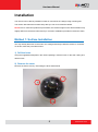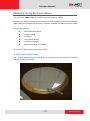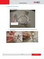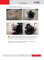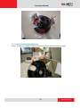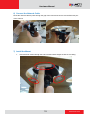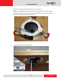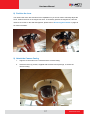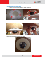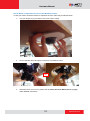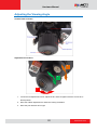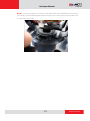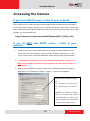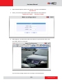
1
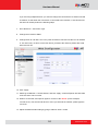
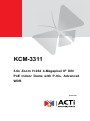
Encoder Firmware V4.06.09 User’s Manual KCM-3311 3.6x Zoom H.264 4-Megapixel IP D/N PoE Indoor Dome with P-Iris, Advanced WDR 2014/01/27 Hardware Manual Table of Contents Precautions ............................................................. 3 Safety Instructions .................................................................................... 4 Introduction ............................................................. 5 Package Contents...................................................................................... 5 Physical Description ................................................................................. 6 Installation ............................................................... 8 Method 1: Surface Installation .................................................................. 8 Method 2: Using the Flush Mount .......................................................... 10 Adjusting the Viewing Angle................................................................... 20 Accessing the Camera ......................................... 22 If you have DHCP server / router in your network: ............................... 22 If you do NOT have DHCP server / router in your network: ................. 22 2 www.acti.com Hardware Manual Precautions Read these instructions You should read all the safety and operating instructions before using this product. Heed all warnings You must adhere to all the warnings on the product and in the instruction manual. Failure to follow the safety instructions given may directly endanger people, cause damage to the system or to other equipment. Servicing Do not attempt to service this video device yourself as opening or removing covers may expose you to dangerous voltage or other hazards. Refer all servicing to qualified service personnel. Trademarks All names used in this manual are probably registered trademarks of respective companies. Liability Every reasonable care has been taken during the writing of this manual. Please inform your local office if you find any inaccuracies or omissions. We cannot be held responsible for any typographical or technical errors and reserve the right to make changes to the product and manuals without prior notice. FCC/CE Regulation Note: This equipment has been tested and found to comply with the limits for a Class A digital device, pursuant to Part 15 of the FCC Rules. These limits are designed to provide reasonable protection against harmful interference when the equipment is operated in a commercial environment. This equipment generates, uses, and can radiate radio frequency energy and, if not installed and used in accordance with the instruction manual, may cause harmful interference to radio communications. Operation of this equipment in a residential area is likely to cause harmful interference in which case the users will be required to correct the interference at their own expense. 3 www.acti.com Hardware Manual Safety Instructions Cleaning Disconnect this video product from the power supply before cleaning. Attachments Do not use attachments not recommended by the video product manufacturer as they may cause hazards. Do not use accessories not recommended by the manufacturer Only install this device in a dry place protected from weather. Servicing Do not attempt to service this video product yourself. Refer all servicing to qualified service personnel. Damage Requiring service Disconnect this video product from the power supply immediately and refer servicing to qualified service personnel under the following conditions: 1) When the power-supply cord or plug is damaged. 2) If liquid has been spilled or objects have fallen into the video product. 3) If the inner parts of the video product have been directly exposed to rain or water. 4) If the video product does not operate normally by following the operating instructions in this manual. Adjust only those controls that are covered by the instruction manual, as an improper adjustment of other controls may result in damage, and will often require extensive work by a qualified technician to restore the video product to its normal operation. Safety Check Upon completion of any service or repairs to this video product, ask the service technician to perform safety checks to determine if the video product is in proper operating condition. 4 www.acti.com Hardware Manual Introduction Package Contents KCM-3311 QIG Accessories Warranty Card Drill Template 5 www.acti.com Hardware Manual Physical Description 1) Reset Button Step 1: Switch off IP device by disconnecting the power cable Step 2: Press and continue to hold the Reset Button (with a sharp tipped object, like a pen.) Step 3: Reconnect the power cable while continuing to hold the reset button. The red Power LED light will flash on for 3 second first, turn off for about 15 seconds, flash on for another second and turn off again. By this time the reset to default operation is already completed. This will take around 20 seconds from power up. You may then release the reset button. This length of time fluctuates slightly with the environment. The Power LED light will come back on and stay on after a few more seconds. The unit will start up with factory default settings automatically. Restore to Default Complete Power On On (3s) On 1s Off (about 15s) Off (10~15s) Stay On About 20 Seconds 6 www.acti.com Hardware Manual 2) Power Button Press the Power Button and then camera will reboot automatically. 3) Ethernet Port The IP device connects to the Ethernet via a standard RJ45 connector. Supporting NWAY, this IP device can auto detect the speed of local network segment (10Base-T/100Base-TX Ethernet). 7 www.acti.com Hardware Manual Installation The camera can be directly installed on walls or mounted in the ceilings using mounting kits. This section describes the two basic ways that you can do to install the camera. NOTE: Due to continuous product improvements, the camera images on this documentation may slightly differ from the actual camera that you received. Installation procedures remain the same. Method 1: Surface Installation You may directly drill holes on the wall or the ceiling and directly install the camera on a surface. To do this, follow the procedures below: 1) Drill the holes Using the supplied drill template in the camera package, mark the holes on the wall / ceiling and drill the holes. 2) Remove the cover Remove the dome cover by unscrewing the three attachments 8 www.acti.com Hardware Manual 3) Screw the camera to the wall/ceiling CAUTION: When using electric screwdrivers, be careful not to touch the internal camera components while attaching the screws. Since electric screwdrivers vary in sizes, speed, and force, they may bruise and damage the internal camera components. DISCLAIMER: ACTi will not be responsible for camera damage caused by improper installations or the misuse of equipment for installation. 4) Connect cables to connectors Please follow the instructions in the Physical Description section for how to connect to each connector. 9 www.acti.com Hardware Manual Method 2: Using the Flush Mount You can use the PMAX-1008 flush mount to mount the camera on ceilings. NOTE: Due to continuous product improvements, the camera images on this documentation may slightly differ from the actual camera that you received. Installation procedures remain the same. Prepare the following: PMAX-1008 Flush Mount Drilling template Screws (3) Foam rubber pads (3) Jig saw (not supplied) Phillips screwdriver (not supplied) To mount the camera, follow the procedures below: 1) Drill a Hole on the Ceiling Drill a 184-mm diameter hole on the ceiling where you want to mount the camera, then route the network cable through the hole. 10 www.acti.com Hardware Manual 2) Remove the Camera Casing Remove the three (3) screws to detach the camera casing. 11 www.acti.com Hardware Manual 3) Prepare the Flush Mount 1. Unpack the flush mount. Retaining bracket 2. Peel off the lining of the three (3) foam rubber pads and attach a rubber pad to each retaining bracket. 12 www.acti.com Hardware Manual 4) Attach the Camera to the Mount 1. Align the screw holes on the camera to the screw holes on the mount. 2. Attach the three (3) screws to secure the camera to the mount. CAUTION: When using electric screwdrivers, be careful not to touch the internal camera components while attaching the screws. Since electric screwdrivers vary in sizes, speed, and force, they may bruise and damage the internal camera components. DISCLAIMER: ACTi will not be responsible for camera damage caused by improper installations or the misuse of equipment for installation. 13 www.acti.com Hardware Manual 5) Loosen the Retaining Brackets Using a screwdriver, loosen the retaining brackets according to the thickness of the ceiling. 14 www.acti.com Hardware Manual 6) Connect the Network Cable Route the network cable to pass through the gap of the mount and connect it to the Ethernet port of the camera. 7) Install the Mount 1. Insert the flush mount through the hole until the bracket edges are flat on the ceiling. 15 www.acti.com Hardware Manual 2. Position the retaining brackets to hold the mount on the ceiling. NOTE: The following illustration shows how the flush mount will look like when viewed from inside the ceiling. In case you cannot access inside the ceiling, use your fingers to position the retaining brackets through the hole. 3. Tighten the screws to secure the mount. 16 www.acti.com Hardware Manual 8) Position the Lens The camera has zoom lens and auto focus capabilities so you do not need to manually adjust the focus. Position the lens on the target view area. To accurately position the target area, view the camera’s Live View on the Web Configurator, please refer to Accessing the Camera on page 22 for more information. 9) Attach the Camera Casing 1. Align the screw holes on the camera and the camera casing. 2. Attach the three (3) screws, supplied with the flush mount package, to secure the camera casing. 17 www.acti.com Hardware Manual 10) Attach the Flush Mount Cover 1. Align the metal latches and the latches on the flush mount cover. 2. Push to firmly secure the flush mount cover latches. The mounted camera should look like the image below: 18 www.acti.com Hardware Manual How to Reset or Reposition the Lens of the Mounted Camera In case you need to reset the camera or reposition the lens, follow the procedures below: 1. Use your fingers to pry the flush mount cover off the ceiling. 2. Insert a pointed object through the reset hole or position the lens. OR 3. Attach the flush mount cover, please refer to Attach the Flush Mount Cover on page 18 for detailed instructions. 19 www.acti.com Hardware Manual Adjusting the Viewing Angle Camera Parts Overview Adjustment Procedures 3 2 1 1. Loosen the tilt adjustment screws, adjust the tilt, and then tighten back the screws to fix the tilt position. 2. Move the rotation adjustment to rotate the viewing orientation. 3. Move the pan direction left or right. 20 www.acti.com Hardware Manual NOTE: If you need to tighten or loosen the pan adjustment knob and adjustment by hand is not enough, insert the bundled pan bracket wrench into the hole on the knob and then push it to the left or to the right. 21 www.acti.com Hardware Manual Accessing the Camera If you have DHCP server / router in your network: Many network server / routers are able to automatically provide IP addresses through DHCP. If you are using such a network, just plug in your computer and IP Dome Cam into the network and your IP device will acquire network address by itself. Find and access the device with our IP Utility program. You may download it at: http://www.acti.com/product/detail/Software/ACTi_Utility_Suite If you do NOT have DHCP server / router in your network: 1. Configure your PC to use the same subnet by changing your PC’s IP address to the subnet with prefix 192.168.0.XXX. The last number should be anything from 1 to 254 except 100 and other occupied IP addresses. Subnet mask should be 255.555.255.0. 2. The default IP used by this device is 192.168.0.100. Please make sure your PC is NOT using this address and that no two equipments use the same IP address in the network. 3. Change your IP address by going to Control Panel ->Manage Network Connections -> Right click on the connection to change -> Option -> TCP/IP IPv4 Properties. Please set the settings as below. IP address: 192.168. 0.xxx Subnet mask: 255.255.255. 0 (NOTE: xxx should be a number from 1 to 254 except 100, which is used by the IP device. Please also make sure that no two equipments use the same IP address in the same network..) 22 www.acti.com Hardware Manual 4. Open Internet Explorer (Version 6.0 or above) , and type in the Default IP: 192.168.0.100 5. When you see the login window, please input default user and password: Default User: Admin Password: 123456 6. After logging in, you will see the video from camera. To go to the main menu, click the ”Setup” button on the top left. If you are using a single camera, this is enough to access the device. 23 www.acti.com Hardware Manual If you are using multiple devices, you need to change the current device to another unused IP address, so that when the next device is connected to the network, no two devices use the same IP. Please perform the following steps. 7. Go to Network -> Connection Type 8. Change the IP mode to Static. 9. Change the IP to 192.168.0.101 or any other unused IPs. Do NOT use the PC’s IP address or 192.168.0.100.). If this is not the first device you add to the network, please also avoid other devices’ IPs. 10. Click “Apply” 11. Please go to Maintain -> Save & Reboot, and click ”Apply”. Internet Explorer will close after a few seconds. This is normal. 12. Wait for 30 seconds, and open IE again to connect to the new IP. (In this example, 192.168.0.101). For the second device or more you add into the network, please type the correct IP. 13. Adjust the default Video setting by going to Video & Audio ->Video 24 www.acti.com