1
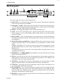
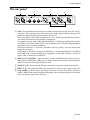
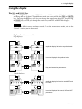
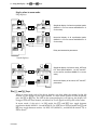
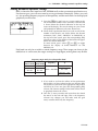
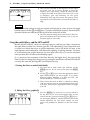
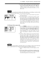
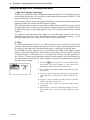
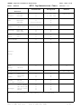
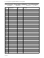
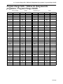
PARAMETRIC EQUALIZER
OPERATING MANUAL
MANUEL D’UTILISATION
BEDIENUNGSHANDBUCH
INPUT LEVEL
+10
L
YDP2006
R
CLIP
-6
-12
-18
-24
-30
-36
-42
MEMORY
PARAMETRIC
EQUALIZER
R
L
0
F
G
POWER
Q
STORE
NOTCH
1
2
3
4
HPF
LPF
PEQ
1
2
3
4
5
6
MEMORY
PEQ
NOTCH
UTILITY
L
R
BYPASS
RECALL
ON
OFF
FCC INFORMATION (U.S.A.)
CANADA
1. IMPORTANT NOTICE: DO NOT MODIFY THIS UNIT!
This product, when installed as indicated in the instructions
contained in this manual, meets FCC requirements.
Modifications not expressly approved by Yamaha may void your
authority, granted by the FCC, to use the product.
This digital apparatus does not exceed the “Class B” limits for
radio noise emissions from digital apparatus set out in the Radio
Interference Regulation of the Canadian Department of
Communications.
2. IMPORTANT: When connecting this product to accessories
and/or another product use only high quality shielded cables.
Cable/s supplied with this product MUST be used. Follow all
installation instructions. Failure to follow instructions could void
your FCC authorization to use this product in the USA.
Le présent appareil numérique n’émet pas de bruits radioélectriques dépassant les limites applicables aux appareils
numériques de la “Classe B” prescrites dans le Règlement sur le
brouillage radioélectrique édicté par le Ministère Des
Communications du Canada.
3. NOTE: This product has been tested and found to comply with
the requirements listed in FCC Regulations, Part 15 for Class
“B” digital devices. Compliance with these requirements
provides a reasonable level of assurance that your use of this
product in a residential environment will not result in harmful
interference with other electronic devices. This equipment
generates/uses radio frequencies and, if not installed and used
according to the instructions found in the users manual, may
cause interference harmful to the operation of other electronic
devices. Compliance with FCC regulations does not guarantee
that interference will not occur in all installations. If this product
is found to be the source of interference, which can be
determined by turning the unit “OFF” and “ON”, please try to
eliminate the problem by using one of the following measures:
Relocate either this product or the device that is being affected
by the interference.
Utilize power outlets that are on different branch (circuit breaker
or fuse) circuits or install AC line filter/s.
In the case of radio or TV interference, relocate/reorient the
antenna. If the antenna lead-in is 300 ohm ribbon lead, change
the lead-in to co-axial type cable.
If these corrective measures do not produce satisfactory
results, please contact the local retailer authorized to distribute
this type of product. If you can not locate the appropriate
retailer, please contact Yamaha Corporation of America,
Electronic Service Division, 6600 Orangethorpe Ave, Buena
Park, CA 90620
*This applies only to products distributed by YAMAHA CORPORATION
OF AMERICA
YDP2006
*This applies only to products distributed by YAMAHA CANADA
MUSIC LTD.
IMPORTANT NOTICE FOR THE UNITED KINGDOM
Connecting the Plug and Cord
WARNING: THIS APPARATUS MUST BE EARTHED
IMPORTANT: The wires in this mains lead are coloured in accordance with the following code:
GREEN-AND-YELLOW
BLUE
BROWN
:
:
:
EARTH
NEUTRAL
LIVE
As the colours of the wires in the mains lead of this apparatus may
not correspond with the coloured markings identifying the
terminals in your plug, proceed as follows:
The wire which is coloured GREEN-AND-YELLOW must be
connected to the terminal in the plug which is marked by the letter
E or by the safety earth symbol
or coloured GREEN or
GREEN-AND-YELLOW.
The wire which is coloured BLUE must be connected to the
terminal which is marked with the letter N or coloured BLACK.
The wire which is coloured BROWN must be connected to the
terminal which is marked with the letter L or coloured RED.
Contents
Congratulations ...................................................................................................................................... 2
Precautions .............................................................................................................................................. 3
The front panel ....................................................................................................................................... 4
The rear panel ......................................................................................................................................... 5
Memory areas ......................................................................................................................................... 6
How the memories are arranged in the YDP2006 ........................................................................... 6
Recalling an equalization setting ....................................................................................................... 6
Storing an equalization setting ........................................................................................................... 6
A note on software protection ........................................................................................................... 6
Using the display .................................................................................................................................... 7
The [PEQ] and [NOTCH] keys ................................................................................................................. 7
Display when in stereo mode ............................................................................................................ 7
Display when in mono mode ............................................................................................................. 8
The [L/<] and [R/>] keys ........................................................................................................................ 8
Linking channels .................................................................................................................................. 9
The PEQ, notch and HPF and LPF indicators ................................................................................... 9
Utilities ................................................................................................................................................... 10
SYSTEM SETUP .................................................................................................................................. 10
TITLE EDIT .......................................................................................................................................... 10
BULK DUMP ...................................................................................................................................... 11
Y-485 NETWORK .............................................................................................................................. 11
Y-485 COMM. I/O ............................................................................................................................ 12
PARAMETER COPY ........................................................................................................................... 12
SOFTWARE PROTECT ....................................................................................................................... 13
MIDI CONTROL ................................................................................................................................ 13
DELAY DISPLAY ................................................................................................................................ 13
TUTORIAL ............................................................................................................................................. 14
Finding a suitable memory area in which to store the setting ...................................................... 14
Initializing the memory area ............................................................................................................ 14
Linking the L and R channels ............................................................................................................ 14
Making parametric equalizer settings ............................................................................................. 15
Using the notch filters, and the HPF and LPF ................................................................................. 16
I. Turning the filters on and off individually .................................................................................... 16
II. Editing the filters graphically ...................................................................................................... 16
III. Editing the filters numerically .................................................................................................... 17
Setting up the input level, attenuation and delay .......................................................................... 18
I. Input level and input attenuation ................................................................................................. 18
II. Delay .......................................................................................................................................... 18
Specifications ........................................................................................................................................ 19
MIDI Implementation Chart ............................................................................................................. 65
User programs ...................................................................................................................................... 66
Program change table .......................................................................................................................... 67
Block diagram ....................................................................................................................................... 68
Dimensions ............................................................................................................................................ 69
YDP2006
English
1 – Contents
2 – Congratulations
Congratulations
Your new YDP2006 Digital Parametric Equalizer uses the most advanced Yamaha digital
signal processing to provide extremely precise, stable equalization.
As well as a stereo 6 band parametric equalizer, the YDP2006 Digital Parametric Equalizer
has a high and low pass filter, and 4 notch filters which can be used to selectively “knock
out” specific frequencies. When running in mono mode, the YDP2006 provides not 6, but 12
bands, and 8 notch filters. Furthermore, the unit can operate at either 6 or 12dB cut/boost.
If you are used to using conventional analog parametric equalizers with knobs you will find
the YDP2006 very easy to use. Selecting “knobs” and “turning” them are simple operations
performed with rotary encoders on the front panel. With a multi-function LCD screen, you
can see at a glance exactly which “knob”, or notch filter you are moving. Or if you prefer,
you can change to a purely numeric display for the parametric filter and notch filter parameters.
One of the biggest advantages of Yamaha digital equalizers (apart from their stunning 20 bit
sound) is the ability to store the equalizer settings you create for instant recall. The YDP2006
has the ability to store 40 different settings in this way, avoiding the need to completely
reconfigure the knobs every time the unit has to be used for a different purpose, or in
another environment.
In order to satisfy the most demanding needs of music professionals, the YDP2006 is able to
be controlled not only by MIDI, but also by the new standard Y-485 interface. This allows for
the fastest possible system configuration, without having to use up an extra MIDI channel to
send program changes.
We urge you to read this manual carefully before using this unit, in order to fully appreciate,
and be able to take advantage of, the many advanced features it offers.
YDP2006
3 – Precautions
Precautions
Avoid excessive heat, humidity, dust and vibration
Keep the unit away from locations where it is likely to be exposed to high temperatures or
humidity - such as near radiators, stoves, etc. Also avoid locations which are subject to
excessive dirt accumulation or vibration which could cause mechanical damage.
Avoid physical shocks
Strong physical shocks to the unit can cause damage. Handle it with care.
Do not open the unit, or attempt repairs or modifications yourself
This product contains no user-serviceable parts. Refer all maintenance to qualified Yamaha
service personnel. Opening the unit and/or tampering with the internal circuitry will void
the warranty.
Make sure power is off before making or removing connections
Always turn the power OFF prior to connecting or disconnecting cables. This is important
to prevent damage to the unit itself as well as other connected equipment.
Handle cables carefully
Always plug and unplug cables - including the AC cord - by gripping the connector, not the
cord.
Clean with a soft dry cloth
Never use solvents such as benzine or thinner to clean the unit. Wipe clean with a soft, dry
cloth.
Always use the correct power source
Make sure that the power source voltage specified on the rear panel matches your local AC
mains supply:
U.S. & Canadian Model: 120V AC, 60Hz
General Model: 230V AC, 50Hz
UK and Australian Model: 240V AC, 50Hz
Backup battery
The unit contains a long-life lithium battery which maintains the contents of the buffer and
user memory locations even when the unit is off. With normal use, the battery should last
approximately 5 years. If the battery voltage falls below a certain level, a “***WARNING***
LOW BATTERY” message will appear on the screen when the power is turned on. If this
occurs, have the battery replaced by at a qualified Yamaha service center. Do not attempt to
replace the battery yourself!
YDP2006
4 – The front panel
The front panel
2
1
3
4
5
INPUT LEVEL
+10
L
CLIP
-6
-12
-18
-24
-30
-36
-42
MEMORY
PARAMETRIC
EQUALIZER
R
L
0
F
G
POWER
Q
STORE
NOTCH
1
2
3
4
HPF
LPF
PEQ
1
2
3
4
5
6
MEMORY
R
8 9 :
7
6
PEQ
NOTCH
UTILITY
L
R
BYPASS
RECALL
ON
A
OFF
B
From left to right, the controls on the front panel are:
1 INPUT LEVEL – two concentric rotary controls (inner control is left channel) to adjust the
level of the signal fed into the YDP2006.
2 Level meters – L and R – These meters come after the A-D convertors in the signal chain.
A “CLIP” indication therefore indicates digital distortion, and the input levels should be
adjusted so that the “CLIP” indicators never light.
3 Memory – this 2-digit LED indicator shows the current memory area.
4 Screen – this 56 x 128 pixel display gives a graphic representation of the current equalization settings. It is also used to display other settings which you can edit using the
front panel controls.
5 Rotary encoders – the F, G and Q controls are used primarily for setting the Frequency,
Gain and Q of equalization bands. When editing utility settings, they may also be used
for editing data.
6 PEQ/NOTCH selectors and indicators – When the PEQ key 8 is lit, the selectors are used
to select a band from PEQ 1–6 (or either MONO.L 1–6, or MONO.R 1-6 when in mono
mode).
When the NOTCH key 9 is lit, they are used to select a band among notches 1–4, and
the HPF and LPF filters or, when in mono mode, MONO.L (1–4 and HPF and LPF) or
MONO.R (1-4).
The indicators show the status of the various bands/filters, and light when the corresponding band/filter is on.
7 MEMORY keys – the [STORE], [RECALL], [^] and [%] keys are used to read and write settings
stored in the 40 memory areas.
8 PEQ key – pressing this key will show the parameters for the parametric equalizer (in
either graphic or numerical form), and enable the PEQ selectors. The indicators will
show the on/off status of the parametric bands.
9 NOTCH key – pressing this key will show the parameters for the notch filters (in either
graphic or numerical form), and enable the NOTCH selectors and indicators.
0 UTILITY key – pressing this key will cycle through a range of screens, allowing you to set
up various system parameters for the unit.
A [L/<] and [R/>] keys – you can make equalization settings for the left and right channels
independently. These keys allow you to select which channel you are editing. By pressing one of these keys, holding it down, and then pressing the other, you can edit the
parameters of both channels simultaneously.
B BYPASS key – when pressed, the signal fed into the unit will bypass the internal circuitry,
and will be re-output “as is”.
YDP2006
5 – The rear panel
The rear panel
1
2
Y-485
OUTPUT
MIDI
THRU
OUT
4
3
IN
R
-20dB
INPUT
R
L
+4dB
-20dB
L
+4dB
5
1 Y-485 – these bi-directional connectors are used to connect the unit on a network “chain”
using the Y-485 control protocol. They do not carry audio signals. When making a Y-485
connection, either terminal may be used for IN or OUT.
Please use digital audio cable (impedance 90~120 Ω shield type equilibrium transmission cable) for connection with periphery equipment.
Using general analog audio cable (impedance 40~50 Ω shield type equilibrium transmission cable) could cause trouble such as signal reflection due to mismatching impedance
and transmission waveform turbulence.
Waveform turbulence is especially noticeable with long cables, and with multi cable
longer than 10 meters.
If the length of the cable is longer than 100 meters, it is recommended that it should be
terminated with a resistor matching the impedance of the cable (connect a resistor of
approx. 100 Ω between Pin 2 and Pin 3).
2 MIDI IN, OUT and THRU – These terminals are used for MIDI control of the unit. IN is
used to receive MIDI data, THRU passes along information received at the IN terminal,
and OUT transmits data originated by the unit.
3 OUTPUT (L, R) – these balanced XLR-type connectors output the signal from the unit.
4 INPUT (L, R) – these balanced XLR-type connectors are used to input signals to the unit.
5 Level switches – both the input and output connectors may be set to nominal levels of
+4dB or -20dB. When connecting other equipment, refer to the specifications of the other
units to match the signal levels correctly.
YDP2006
6 – Memory areas
Memory areas
How the memories are arranged in the YDP2006
The unit contains 40 memory areas which contain equalization settings, all of which are
user-programmable. This allows you to set up and store frequently-used equalization settings which you can recall at any time. These settings can be stored to a mass-storage device
(MIDI data file system or personal computer system) either through the MIDI interface, or
the Y-485 connectors (see the section on “Utilities” for full details of this).
Recalling an equalization setting
Use the MEMORY [^] and [%] keys to display the name of the setting you want to recall. The
name (set in UTILITY mode) is shown in the middle of the display, and the memory number
flashes on the LED display.
Press the [RECALL] key.
If you had not made any changes to the previous setting, the new setting will be displayed
immediately.
If you had made changes to the previous setting without storing them, the unit will flash
“RECALL OK?” in the center of the screen. If you really want to recall this setting, press the
[RECALL] key again (while this message is flashing, you can use the MEMORY [^] and [%]
keys to select another setting to be recalled). If you press the [RECALL] key, the number in the
LED will stop flashing, and the screen will show the equalization curve for this setting. If
you have made a mistake in selecting the setting or pressing the [RECALL] key in the first
place, and do not want to recall the setting, press any key except the [RECALL] key.
Remember that the equalization curve shown will be for either the left or the right channel,
depending on whether the [L/<] or [R/>] key is lit.
Storing an equalization setting
When you have edited a setting, you use the MEMORY [^] and [%] keys to select a memory
area where you want to store the setting (if the memory area you are editing is the area
where you want to store the setting, you do not need to press the [^] and [%] keys). As you
step through the memory areas, the name of each one will be displayed in the center of the
screen.
When you have selected the area, press the [STORE] key to write these settings into memory.
The unit will flash “STORE OK?” in the center of the screen. Press the [STORE] key again to
confirm the store, or any other key to cancel the store.
A note on software protection
You can protect the settings against accidental key-presses, etc., by using the UTILITY software protection (see “SOFTWARE PROTECT” on page 3). If protection is set to ON, then
any attempt to store or recall settings using the methods described above will result in the
message “ERR ** NOW PROTECT” being shown on the screen. The 2-digit LED will start to
flash if you attempt to recall, store or modify a setting with protection on, as an additional
warning. If you get the “ERR ** NOW PROTECT” message when trying to perform any
operations with protection on, press any key to stop the LED flashing. “ERR ** NOW PROTECT” will disappear from the screen.
YDP2006
7 – Using the display
Using the display
The [PEQ] and [NOTCH] keys
Using the large LCD screen, your YDP2006 has several different ways of displaying settings,
and being able to edit them. These different modes are accessed with the [PEQ] and [NOTCH]
keys. Pressing the [PEQ] key will take you through the equalization displays, and pressing
the [NOTCH] key will take you through the notch filter, and LPF and HPF filter displays.
NOTE
The displays differ in mono and stereo mode. To set the mono/stereo mode, refer to the
“Utilities” section, later in the manual.
Display when in stereo mode:
PEQ displays:
PEQ
PEQ
L
Graphical display of all active equalizer bands.
R
PEQ
PEQ
L
R
PEQ
Numerical display of all equalizer bands.
PEQ
L
R
Delay and attenuation parameters.
Notch displays:
NOTCH
NOTCH
L
Graphical display of all active notch, HPF and
LPF filters.
R
NOTCH
NOTCH
L
R
Numerical display of the notch, HPF and LPF
parameters.
YDP2006
8 – Using the display – The [L/<] and [R/>] keys
Display when in mono mode:
PEQ displays:
PEQ
PEQ
L
Graphical display of all active equalizer bands
(MONO.L 1-6 on one screen and MONO.R 1-6
on the other).
R
PEQ
PEQ
L
Numerical display of all equalization bands
(MONO.L 1-6 on one screen and MONO.R 1-6
on the other).
R
PEQ
PEQ
Delay and attenuation parameters.
Notch displays:
NOTCH
NOTCH
Graphical display of all active notch, HPF and
LPF filters (filters MONO.L 1-4, HPF and LPF
on one screen, and filters MONO.R 1-4 on the
other).
Mono
L
R
NOTCH
NOTCH
L
R
Numerical display of the notch, HPF and LPF
parameters.
The [L/<] and [R/>] keys
When in stereo mode, each of the above displays can show either the settings for the left
channel, or the settings for the right channel. To select which channel will be displayed,
press the [L/<] or [R/>] key. The LED on the corresponding key will light up, the display will
change to show the new channel, and either R or L will appear in the top left of the screen.
In mono mode, if the unit is in PEQ mode, the [L/<] and [R/>] keys toggle between
equalization bands MONO.L 1-6 and MONO.R 1-6. If the unit is in notch mode, the [L/<] and
[R/>] keys toggle between notches 1-4, HPF, LPF (MONO.L), and MONO.R notches 1-4, as
shown above.
YDP2006
9 – Using the display – Linking channels
Linking channels
In order to change both the L and R channels at the same time, the L and R channels must be
linked. When the channels are linked, making any changes to one channel will also affect
the other. Existing parameters from one channel will not be copied to the other channel,
unless they are altered while the channels are linked.
To link the channels, press one of the two channel keys (either [L/<] or [R/>]), and while holding it down, press the other one. Because the screen can only show one channel at a time,
only the settings of the first channel you pressed will be displayed, and the LED on that key
will light. The settings of the other channel will not be displayed, and its LED will blink.
The PEQ, notch and HPF and LPF indicators
NOTCH
1
2
3
4
HPF
LPF
PEQ
1
2
3
4
5
6
The small round LEDs above the PEQ and notch selectors indicate whether or not the corresponding PEQ band, or notch filter is active (turned on). When the LED on the PEQ key is
on, the row of indicators refers to the PEQ bands. When the LED on the NOTCH key is on,
the row of indicators refers to the notch, and LPF and HPF filters.
To turn a specific notch, filter or PEQ band on or off, it must first be selected for editing. If
the parameters for the desired band are not displayed at the top of the screen (in graphical
display screens), or the name of the notch highlighted on the left of the screen (in the text
display modes), you must press the selector twice—once to select which notch, filter or PEQ
band to change (this also selects it for editing), and once to toggle it between on and off. If
the notch, filter or PEQ band is already selected for editing, simply pressing the selector
once will do the toggling.
Put more simply, if you wish to toggle a notch, filter on/off that is already selected, just
press the selector once. If it’s not selected, press the selector twice.
YDP2006
10 – Utilities
Utilities
The [UTILITY] key allows you to set up various system parameters for the unit. Repeated
presses of the key will cycle you through the following modes. You can also use the [%] and
[%] keys to cycle through these parameters (but this will not return to the equalization setting display):
The [UTILITY] key will be lit for all these displays
SYSTEM SET UP
TITLE EDIT
BULK DUMP
Y-485 NETWORK
Equalization
setting display
Y-485 COMM. I/O
DELAY DISPLAY
MIDI CONTROL
SOFTWARE PROTECT
PARAMETER COPY
NOTE
You can also exit the UTILITY mode by pressing either the [PEQ] or [NOTCH] key.
SYSTEM SETUP
If you are in stereo mode, you will only have one parameter here: EMPHASIS. If you are in
mono mode, you will also have the option (INP. MODE) of whether the signal is taken from
the left or right input.
The emphasis function is a type of noise reduction and can effectively be used to reduce the
high-frequency noise produced during A/D conversion and D/A conversion. It causes
some deterioration of the dynamic range in the high-frequency range, however.
Because this equipment uses a 20-bit AD/DA converter, a sufficient dynamic range is
assured even when the emphasis function is turned off. Setting it to OFF will work best for
most material most of the time.
Emphasis: Use the F encoder to turn emphasis on and off
(this trips an internal relay, so you will hear a “click” as
this is switched).
Input mode: Use the G encoder (if you’re in mono mode)
to set the input mode to either “L-MONO” (the signal is
taken from the left channel input) or “R-MONO” (the signal is taken from the right input). This option is only available in mono mode.
TITLE EDIT
Each equalization setting may have a name. This may be useful in a mobile PA setup which
is often used at the same venues at different times (a setting named “UNIV. STADIUM” is
easier to remember again than program 23). Names set using this function are displayed on
the screen whenever you step through the memory areas using the [%] or [^] keys.
Use the F encoder to select a character (0-9, A-Z, a-z +
punctuation) and the [L/<] and [R/>] keys as cursor keys to
determine which character will be edited. Use the [STORE]
key as an easy way to enter a space.
YDP2006
11 – Utilities – BULK DUMP
BULK DUMP
Three parameters are available here:
Use the F encoder to select whether bulk dump operations
will take place through the MIDI or Y-485 connections.
Use the G encoder to select what kind of data will be
dumped. You can choose between: ALL DATA (all memory
areas will be dumped), SYSTEM (the parameters you set
up in the UTILITY menus will be dumped), MEMORY (a
single memory area, or all memory areas will be dumped),
and BANK (the Program Change tables).
If you have selected MEMORY with the G encoder, use the
Q encoder to select the memory area that you want to
dump (1 through 40 or ALL).
If you have selected BANK with the G encoder, use the Q
encoder to select the Program Change bank you want to
dump (A through D or ALL).
NOTE
You can dump this data over MIDI to a MIDI data filer device (including a personal computer), or over the Y-485 network to a computer connected through the YAMAHA IFU485
interface.
There is no need to set the unit into any special receive mode to receive bulk dump data
from an external device.
Y-485 NETWORK
The Y-485 network is more complex (in terms of software addressing) than the MIDI system.
Each device on a network belongs to a group and has a device number within that group.
Use the [L/<] and [R/>] keys to decide whether you are editing the REMOTE or LOCAL settings. The LOCAL settings,
of course, refer to this unit, and the REMOTE settings refer
to a unit to which you will be sending data.
The F encoder allows you to set up a group number
between 1 and 7. The Y-485 protocol allows messages to be
sent to groups of units. If you are editing the REMOTE settings, you can also set this to a “*”. This is a “don’t care”
value – the remote device address is irrelevant, and messages will be sent to all groups.
The G encoder allows you to set a device number inside
the group between 1 and 31. If you are editing REMOTE
settings, you can also set this to a “*”. This is a “don’t care”
value – the remote device address is irrelevant, and messages will be sent to all devices.
The Q encoder allows you to set the data transfer rate for
the LOCAL settings only. This should usually be set to
9600 (even though a value of 38400 may be set).
To control this unit and other Y-485 units from a computer, you will require an IFU485 hardware interface, and computer software (QS-1) to control it. QS-1 software is available for
both Macintosh and IBM-compatible computers. Contact Yamaha or your local Yamaha distributor for further details.
YDP2006
12 – Utilities – Y-485 COMM. I/O
Y-485 COMM. I/O
Only one parameter is available here: the data which will
be recognized by the unit over the Y-485 network. There
are three values, selectable with the F encoder: OFF, PGM
CHANGE and ALL. When OFF, no Y-485 messages will be
recognized by the unit, when PGM CHANGE, only Program Change messages will be recognized by the unit, and
when ALL, any data coming over the Y-485 interface will
be recognized.
NOTE
These parameters are entirely independent of any data received at the MIDI ports.
PARAMETER COPY
This allows you to initialize new equalization settings from a “template” setting and to copy
channel settings. The “template” settings allow you to set the mono/stereo mode, and the
6dB/12dB boost mode.
Use the F encoder to decide what setting you will use as
the default, and where you will copy it to. There are four
“template” settings available:
STEREO 12 is a stereo 6-band parametric EQ with 4 notch
filters (plus HPF and LPF) and gain for each band of
±12dB.
STEREO 6 is a stereo 6-band parametric EQ with 4 notch
filters (plus HPF and LPF) and gain for each band of ±6dB.
MONO 12 is a mono 12-band parametric EQ with 8 notch
filters (plus HPF and LPF) and gain for each band of
±12dB.
MONO 6 is a mono 12-band parametric EQ with 8 notch
filters (plus HPF and LPF) and gain for each band of ±6dB.
Select the “template” you want to use using the F encoder.
The “template” will be copied to the edit area.
After the “template” settings, if the current setting is in stereo mode (STEREO 6 or STEREO 12), turning the F
encoder will bring up two more options: from L-DATA to
R-DATA and from R-DATA to L-DATA. This allows you to
copy from one channel to another. If you are in mono
mode, these options will of course not be available.
Using the G encoder, you can select what data is to be copied between channels: ALL (self-explanatory), EQ (the
parametric equalization settings), FILTER (the notch filter
settings), or DELAY/ATT (the delay and attenuation settings).
Whatever data you have chosen to copy (“template” or channel data) press the [STORE] key
to start the copying process. If you have not set the software protection on, the message “**
EXECUTING” will appear briefly on screen as the data is copied. If software protection is
on, nothing will appear on screen, and no data will be copied when you press the [STORE]
key.
YDP2006
13 – Utilities – SOFTWARE PROTECT
SOFTWARE PROTECT
Use the F encoder to turn memory protection on or off.
When ON, the unit will not respond to Program Change
messages received over MIDI or Y-485. You will not be able
to store or copy any new or edited equalization settings if
protection is ON. “ERR ** NOW PROTECT” will appear on
the screen if you try to store data while protection is ON.
MIDI CONTROL
The unit will respond to MIDI Program Change messages sent from a master keyboard,
sequencer or other device. It may be useful to remap program change settings so that a Program Change message of 2, for instance, selects memory area 40.
There are four “banks” of Program Change tables available
– A through D. Use the [L/<] and [R/>] keys to select which
bank will be edited. The bank displayed on this screen will
remain the active bank after you have exited the UTILITY
mode.
Use the F encoder to select the MIDI channel to which the
bank will respond (OFF, 1 through 16 or OMNI).
Use the G encoder to select the Program Change number
which will be recognized.
Use the Q encoder to select the memory area which will be
recalled when the Program Change number set with the G
encoder is received.
NOTE
The currently-selected Program Change bank is also applicable when a Y-485 Program
Change is received.
DELAY DISPLAY
When using the unit in a sound reinforcement application,
it is very often useful to delay one or both channels to compensate for phase differences caused by speaker placement. In this menu, use the F encoder to select the units in
which this delay will be expressed: FEET, METERS or
SECONDS. The distance units (FEET, METERS) allow you
to enter delay times expressed in distance (select the
appropriate one, depending on your familiarity with the
metric system). The SECONDS option allows you to enter
delay times directly in milliseconds.
YDP2006
14 – TUTORIAL
TUTORIAL
In this section we will go over the setting up of the YDP2006, from the parametric equalizer
and the filters, to the delay and input attenuation. The information is presented as a tutorial—from it, you should be able to pick up the techniques necessary to make settings for
any situation.
Finding a suitable memory area in which to store the setting
This may be an existing equalization setting which you wish to alter, or a completely new
setting that you wish to create from scratch.
1 Ensure you are in one of the display screens (the utility
indicator is off). If you’re in utility mode, press the[PEQ]
or [NOTCH] key.
2 To go to another memory setting, press the MEMORY
[^] or [%] keys until the name of the setting appears on
the screen, and its memory number flashes on the
MEMORY display. Then press [RECALL] once. If you
have edited the settings in the previous memory area,
“RECALL OK?” will appear on the display as a warning—press [RECALL] again to recall the new setting.
3 If you seem to be having problems with this, and “ERR
** NOW PROTECT” appears on the display, the memory is protected. See the “Utilities” section.
Initializing the memory area
If you wish to start creating a setting from scratch, and there is an existing setting at the
memory location you are working at, you can clear the existing setting using the PARAMETER COPY function (see the “Utilities” section). This will also allow you to set whether the
equalizer is in stereo mode (6 PEQ bands, and 4 notch filters per channel), or mono mode (12
PEQ bands, and 8 notch filters), and also whether the maximum cut/boost is 6dB or 12dB.
Settings in the PARAMETER COPY function
Display
Mode
STEREO 12
STEREO 6
MONO 12
MONO 6
Stereo
Stereo
Mono
Mono
Maximum
cut/boost
12dB
6dB
12dB
6dB
Linking the L and R channels
If you are working in stereo mode, you will probably frequently want to set up the L and R
channels identically (at least for most of the settings), and then tweak the L and R channels
separately. Linking the channels is the way to achieve this.
To link the channels, press one of the two channel keys (either [L/<] or [R/>]), and while holding it down, press the other one. Only the settings of the first channel you pressed will be
displayed, and the LED on that key will light.
Linking the channels does not automatically copy all parameters from one channel to the
other. Only the parameters that you create or change while the channels are linked will be
made to both channels.
YDP2006
15 – TUTORIAL – Making parametric equalizer settings
Making parametric equalizer settings
Here is where the user interface of the YDP2006 really makes parametric equalization easy.
For the most part, you will never need to set any parameters numerically (unless you want
to)—the resulting frequency response of the equalizer, and the notch filters can be displayed
graphically on the screen.
1 Press the [PEQ] key until you see a screen similar to the
one shown. The number of the currently selected band
is shown below the channel indication in the top left
corner of the display. The actual settings on your screen
will probably be different to the ones shown here.
2 Select which equalization band you wish to edit. If the
number of this band is not shown below the channel
indication (“Lch”, “Rch”, “MONO.L” or “MONO.R”) at
the top left of the screen, press the corresponding PEQ
selector to select it. The number of the band will appear
below the channel indication.
In mono mode, press either [L/<] or [R/>] to toggle
between the display of bands MONO.L 1-6 and
MONO.R 1-6.
Each band can only be set within a certain frequency range. These ranges are shown in the
table below. As can be seen, the ranges overlap to a large degree, making them very flexible.
Frequency ranges and Q for each equalizer band
Band
Band
Frequency
(Stereo mode) (Mono mode)
L1, R1
L1
L2 – L5
L2 – L6
20 Hz – 20.0 kHz
R2 – R5
R1 – R5
L6, R6
R6
Q
LSH, 0.5 – 10.0
0.5 – 10.0
HSH, 0.5 – 10.0
3 If you wish to see/hear the effects of the equalization
band while it is being edited, make sure that the PEQ
for the band is turned on (the appropriate PEQ indicator LED is lit). If it is not, press the corresponding PEQ
selector. The current settings for the band will be shown
in graphical form on the screen.
4 Turn the F rotary encoder, and notice how the dotted
bar moves to the left and right. This is the frequency
selector—any changes you will make with the gain
rotary encoder affect only this frequency.
YDP2006
16 – TUTORIAL – Using the notch filters, and the HPF and LPF
5 Once you have decided on the frequency for the equalizer band, turn the G rotary encoder to move the
response curve up or down, and the Q rotary encoder
to adjust the width of the band. The values of F, G and
Q (frequency, gain and resonance) are also given
numerically at the top of the screen. This process can be
repeated for each of the bands, to create the desired settings.
NOTE
Remember that the settings for only one channel are displayed at a time, and you can toggle
between them with the [L/<] and [R/>] keys. If you have linked the channels, the channel displayed will be the one indicated at the top left of the screen (Lch or Rch).
6 Once the desired settings have been created, don’t forget to store them in one of the memory areas, so you can
use them again at a later time.
Using the notch filters, and the HPF and LPF
Besides the HPF and LPF, which are shelving high-pass and low-pass filters, respectively,
the notch filters provide very selective gain cuts, with adjustable Q. One of their main uses
is to filter out sounds that occur at specific frequencies, such as 50/60 Hz AC hum, or the
high frequency noise induced by some fluorescent lighting, or lighting dimmers. Of course,
to avoid affecting the original material any more than necessary, try to use the narrowest
notch possible that will remove the offending signals.
Q is a measure of the resonance of the filter. Basically, the higher the Q, the narrower the
notch. Except for setting the Q, the process for setting the notch filters and the HPF and LPF
is exactly the same (the shelving HPF and LPF don’t have Q).
I. Turning the filters on and off individually
1 You must be in notch mode (the indicator on the
[NOTCH] key on). If you are not, then press the [NOTCH]
key.
2 Use the [L/<] or [R/>] keys to select the appropriate left or
right channel display (in stereo mode), or to choose
between notches MONO.L 1-4, HPF and LPF, and
notches MONO.R 1-4 (in mono mode).
3 Then, ensure the notch or filter is selected for editing
(you may need to press the corresponding selector once
to do this), then press the appropriate selector to toggle
it on/off.
II. Editing the filters graphically
1 Press the [NOTCH] key until you see a screen similar to
the one here. If you are in mono mode, there are two
screens like this (accessed with the [L/<] or [R/>] keys)—
one for notches MONO.L 1-4, HPF and LPF, and one for
notches MONO.R 1-4. The actual settings on your
screen will probably be different to the ones shown
here.
YDP2006
17 – TUTORIAL – Using the notch filters, and the HPF and LPF
2 To select a filter for editing (if it’s not already selected),
press one of the notch or filter selectors. The indication
in the top left corner below the “Lch”, “Rch” or
“MONO” indication shows the filter that is currently
selected for editing. It will either show NOT1, 2, 3 or 4,
HPF or LPF.
NOTE
If you wish to see and hear the effects of the filter while you are editing it, make sure the
indicator above the filter selector is on. If not, press the selector.
3 Use the F rotary encoder to move the filter up or down
the frequency band.
4 For the notch filters, use the Q rotary encoder to alter
the Q of the notch. As you adjust the filter parameters,
the F (and Q if you’re not editing the HPF or LPF) will
be shown numerically at the top of the screen. If the filter is turned on (the appropriate indicator is lit), the
screen will show the frequency response of the filter settings. Notice the extra width of the notch on the left,
with Q of 0.5.
III. Editing the filters numerically
1 Press the [NOTCH] key until you see a screen similar to
the one shown. The screen shown is the one displayed
in stereo mode. If you are in mono mode, there are two
screens like this (accessed with the [L/<] or [R/>] keys)—
one for notches MONO.L 1-4, HPF and LPF, and one for
notches MONO.R 1-4. The actual settings on your
screen will probably be different to the ones shown
here.
2 To select a filter for editing (if it’s not already selected),
press one of the notch or filter selectors. The corresponding “NOT”, “HPF” or “LPF” indication on the left
side of the screen will become highlighted, and a cursor
will appear beneath the parameters for the currently
selected filter (either the F or Q parameter will be
underlined). For any filters that are off, a dash (“—”)
will appear in the second column of the display. For filters that are on, this is replaced by a small symbol representing the filter.
NOTE
If you wish to hear the effects of the filter while you are editing it, make sure the indicator
above the filter selector is on. If not, press the appropriate selector to turn it on.
3 Use the F rotary encoder to alter the frequency of the
filter.
4 For the notch filters, use the Q rotary encoder to alter
the Q of the notch. The figure shown is adjustable from
0.5 to 10.0 (10.0 is the narrowest). Of course, the HPF
and LPF shelving filters do not take Q values.
YDP2006
18 – TUTORIAL – Setting up the input level, attenuation and delay
Setting up the input level, attenuation and delay
I. Input level and input attenuation
There are two operations on the YDP2006 that affect the input level—the input level control
in the analog domain (pre A/D converters), and the attenuation parameter (INP.ATT) in the
digital domain (post A/D converters).
The input level control (on the front panel) should be set so that the level meters register the
highest possible level without the CLIP indicator lighting.
The input attenuation parameter is provided to compensate for equalizer settings that alter
the overall gain of the sound. e.g. If the equalizer settings result in an overall gain increase
of 4dB (for example), internal clipping may occur even if the level meters do not indicate
clipping.
As a guide to input attenuation level, adjust it so that the output volume is the same as
when the bypass function is used. The attenuation can be set from 0dB to infinity (∞), with
the highest numerical value being shown as 50 (see instructions below).
II. Delay
In sound reinforcement situations, it is often desirable for the sound from various loudspeakers to be delayed, to compensate for phase delay caused by speaker placement. Due to
its position in the signal chain, the equalization stage is a good place to add this delay.
The YDP2006 can delay signals by up to 714 milliseconds (242m, about 800ft) in stereo
mode, or 1428 milliseconds (485m, about 1593ft) in mono mode. You can input this information either directly as milliseconds, or as a distance in feet or meters (set your preference in
the “Utilities”). You can make individual settings for both channels, or for both channels at
the same time by linking L and R. These settings are stored in the memory area along with
the equalization settings.
1 Press the [PEQ] key until you see a screen similar to the
one shown. The actual settings on your screen will
probably be different to the ones shown here.
2 If you wish to alter both channels simultaneously, link
the channels.
3 Use the F rotary encoder to set the delay. To change the
units used (msec, meters or feet), see the “Utilities” section.
4 Use the G rotary encoder to enable (“ON”) or disable
(“OFF”) the delay you have set.
5 Use the Q rotary encoder to set the channel input
attenuation.
6 Don’t forget to store the completed settings in one of
the memory areas, so you can use them again at a later
time.
YDP2006
19 – Specifications
Specifications
20Hz to 20kHz 0 ±1, 0dB
Frequency response
Dynamic range
Emphasis ON
typical, 110dB
> 104dB
Emphasis OFF
typical, 106dB
> 100dB
Hum and noise
Distortion
Inputs
Outputs
A/D and D/A convertors
Emphasis ON
< -80dBm
Emphasis OFF
<-76dBm
(max level, Emphasis ON)
< 0.007%
(max level, Emphasis OFF)
<0.01%
Channel inputs
2 (balanced)
Nominal input level
+4/–20dBm (switchable)
Maximum input level
+24dBm (switch at +4dB)
Input impedance
20kΩ
Channel outputs
2 (balanced)
Nominal output level
+4/–20dBm (switchable)
Maximum output level
+24dBm (switch at +4dB)
Output impedance
150Ω
A/D resolution
20-bit linear
D/A resolution
20-bit linear
Frequency response
44.1kHz
Memory areas
40 (all user-programmable)
MIDI control
Program Change messages
select memory areas
Power requirements
USA and Canadian model
120V/60Hz
General model
230V/50Hz
UK and Australian model
240V/50Hz
Power consumption
(all models)
25W
Dimensions (w x d x h)
mm (in)
480 x 335 x 45 (18.9 x 13.2 x 1.8)
(19” 1U rackmount)
Weight
kg (lb)
4.6 (10.1)
YDP2006
YAMAHA [Digital Parametric Equalizer]
Model: YDP2006
date: 1993.10.22
MIDI Implementation Chart
Version: 1.0
Transmitted
Recognized
Remarks
Function
Basic
Channel
Default
Changed
X
X
1 - 16, off
1 - 16, off
memorized
Default
Messages
Altered
X
X
**************
OMNI off/OMNI on
X
X
memorized
Mode
:True Voice
X
**************
X
X
Note
Number
Velocity
Note ON
Note OFF
X
X
X
X
After
Touch
Key’s
Ch’s
X
X
X
X
X
X
X
X
X
O
*1
System Exclusive
O
O
Bulk Dump
System
Common
:Song Pos
:Song Sel
:Tune
X
X
X
X
X
X
System
Real Time
:Clock
:Commands
X
X
X
X
Aux
:Local ON/OFF
:All Notes OFF
:Active Sense
:Reset
X
X
X
X
X
X
X
X
Pitch Bender
Control
Change
Prog
Change
Messages
:True #
Notes: *1 = For program 1 - 128, memory 1 - 40 is selected.
Mode 1: OMNI ON, POLY
Mode 3: OMNI OFF, POLY
Mode 2: OMNI ON, MONO
Mode 4: OMNI OFF, MONO
O: Yes
X: No
66 – User programs / Programmes utilisateur / User-Programme
User programs / Programmes utilisateur / User-Programme
Unit number: ________ Programmer: _____________ Backed up to: ________ Date: ______
Memory
area
1
2
3
4
5
6
7
8
9
10
11
12
13
14
15
16
17
18
19
20
21
22
23
24
25
26
27
28
29
30
31
32
33
34
35
36
37
38
39
40
YDP2006
Program name:
Date:
Comments:
67 – Program change table / Tableau de changement de programme / Program-Change-Tabelle
Program change table / Tableau de changement de
programme / Program-Change-Tabelle
Unit number: ________
Received
1
2
3
4
5
6
7
8
9
Selects:
Received
33
34
35
36
37
38
39
40
41
Bank: ________
Selects:
Backed up to: ____________
Received
65
66
67
68
69
70
71
72
73
Selects:
Date: ________
Received
97
98
99
100
101
102
103
104
105
10
11
12
13
14
15
16
17
18
19
20
21
22
23
24
25
42
43
44
45
46
47
48
49
50
51
52
53
54
55
56
57
74
75
76
77
78
79
80
81
82
83
84
85
86
87
88
89
106
107
108
109
110
111
112
113
114
115
116
117
118
119
120
121
26
27
28
29
30
31
32
58
59
60
61
62
63
64
90
91
92
93
94
95
96
122
123
124
125
126
127
128
Selects:
YDP2006
68 – Block diagram / Schéma de principe / Blockdiagramm
Block diagram / Schéma de principe / Blockdiagramm
LEVEL
INPUT
INPUT
LEVEL
Pre
Emphasis
De
Emphasis
HA
L
A/D
ATT
D/A
OFF
L
OFF
ON
+4 -20
OUTPUT
ON
+4 -20
DSP
HA
R
A/D
+4 -20
ATT
D/A
OFF
OFF
ON
ON
MIDI
+4 -20
LCD
IN
KEY
OUT
CPU
LED
THRU
F
G
Rotary
Encoder
Q
Y-485
STEREO MODE
ATT
HPF
LPF
4-band
Notch
6-band
PEQ
Delay
730ms
ATT
HPF
LPF
4-band
Notch
6-band
PEQ
Delay
730ms
DSP
MONO MODE
L
ATT
HPF
LPF
4-band
Notch
6-band
PEQ
R
Delay
1460ms
4-band
Notch
YDP2006
6-band
PEQ
R
69 – Dimensions / Abmessungen
440 (17 5/16")
305.4 (12")
D : 334.9 (13 3/16")
(1/8")
44
W : 480 (18 7/8")
348 (13 11/16")
1.2 (<
1/16")
H : 45.2
(1 3/4")
21
(13/16")
3.6
28.5
(1 1/8")
230.5 (9 1/16")
50
(1 15/16")
4.9 (3/16")
Dimensions / Abmessungen
All measurements given in mm (inches). Inch values given to nearest 1/16”.
Toutes les mesures sont données en millimètres (pouces). Précision d’ 1/16 pour les valeurs en pouces.
Alle Maße in mm (Zoll). Zoll-Angaben mit einer Genauigkeit von 1/16”.
Litiumbatteri!
Bör endast bytas av servicepersonal.
Explosionsfara vid felaktig hantering.
VAROITUS!
Lithiumparisto, Räjähdysvaara.
Pariston saa vaihtaa ainoastaan aian
ammattimies.
ADVARSEL!
Lithiumbatteri!
Eksplosionsfare. Udskiftning mà kun foretages
af en sagkyndig, – og som beskrevet i
servicemanualen.
YDP2006
VQ95590 R2 1 CR
72
97 09 500 CR Printed in Japan
P.O.Box 1,Hamamatsu,Japan