1
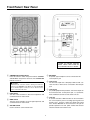
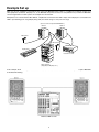
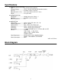
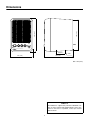
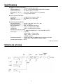
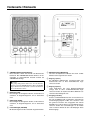
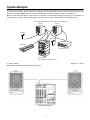
MONITOR SPEAKER
MS101II
OPERATING MANUAL
Thank you for purchasing a Yamaha MS101II Monitor Speaker. The
MS101II employs a 4 inch full-range speaker in a compact bass-reflex style
cabinet. Its faithful sound reproduction capabilities make it ideal for home
recording and personal practice. Since a magnetic field-cancelling speaker
is used, the MS101II can be placed next to a television or video monitor
without causing interference, making it the perfect choice for Audio/Video
system applications.
● Explanation of Graphical Symbols
The lightning flash with arrowhead symbol, within an
equilateral triangle is intended to alert you to the presence of
uninsulated
“dangerous
voltage”
within
the
product’s
enclosure that may be of sufficient magnitude to constitute a
risk of electric shock to persons.
The exclamation point within an equilateral triangle is
intended to alert you to the presence of important operating
and maintenance (servicing) instructions in the literature
accompanying the appliance.
SAFETY INSTRUCTIONS
1.
Read Instructions — All the safety and operating instructions should
be read before the appliance is operated.
13. Cleaning — The appliance should be cleaned only as recommended by the manufacturer.
2.
Retain Instructions — The safety and operating instructions should
be retained for future reference.
3.
Heed Warnings — All warnings on the appliance and in the operating instructions should be adhered to.
14. Nonuse Periods — The power cord of the appliance should be
unplugged from the outlet when left unused for a long period of
time.
4.
Follow Instructions — All operating and use instructions should be
followed.
5.
Water and Moisture — The appliance should not be used near
water — for example, near a bathtub, washbowl, kitchen sink, laundry tub, in a wet basement, or near a swimming pool, and the like.
6.
Carts and Stands — The appliance should
be used only with a cart or stand that is recommended by the manufacturer.
6A. An appliance and cart combination should
be moved with care. Quick stops, excessive
force, and uneven surfaces may cause the
appliance and cart combination to overturn.
7.
Wall or Ceiling Mounting — The appliance should be mounted to a
wall or ceiling only as recommended by the manufacturer.
8.
Ventilation — The appliance should be situated so that its location
or position does not interfere with its proper ventilation. For example, the appliance should not be situated on a bed, sofa, rug, or similar surface that may block the ventilation openings; or placed in a
built-in installation, such as a bookcase or cabinet that may impede
the flow of air through the ventilation openings.
9.
Heat — The appliance should be situated away from heat sources
such as radiators, heat registers, stoves, or other appliances
(including amplifiers) that produce heat.
10. Power Sources — The appliance should be connected to a power
supply only of the type described in the operating instructions or as
marked on the appliance.
11. Grounding or Polarization — The precautions that should be taken
so that the grounding or polarization means of an appliance is not
defeated.
12. Power-Cord Protection — Power-supply cords should be routed so
that they are not likely to be walked on or pinched by items placed
upon or against them, paying particular attention to cords at plugs,
convenience receptacles, and the point where they exit from the
appliance.
15. Object and Liquid Entry — Care should be taken so that objects do
not fall and liquids are not spilled into the enclosure through openings.
16. Damage Requiring Service — The appliance should be serviced by
qualified service personnel when:
A.
The power-supply cord or the plug has been damages; or
B.
Objects have fallen, or liquid has been spilled into the appliance; or
C.
The appliance has been exposed to rain; or
D.
The appliance does not appear to operate normally or exhibits
a marked change in performance; or
E.
The appliance has been dropped, or the enclosure damaged.
17. Servicing — The user should not attempt to service the appliance
beyond that described in the operating instructions. All other servicing should be referred to qualified service personnel.
18. Attachments — Do not use attachments not recommended by the
product manufacturer as they may cause hazards.
19. Power Lines — An outside antenna system should not be located in
the vicinity of overhead power lines or other electric light or power
circuits, or where it can fall into such power lines or circuits. When
installing an outside antenna system, extreme care should be taken
to keep from touching such power lines or circuits as contact with
them might be fatal.
20. Overloading — Do not overload wall outlets, extension cords, or
integral convenience receptacles as this can result in a risk of fire or
electric shock.
21. Replacement Parts — When replacement parts are required, be
sure the service technician has used replacement parts specified by
the manufacturer or have the same characteristics as the original
part. Unauthorized substitutions may result in fire, electric shock, or
other hazards.
22. Safety Check — Upon completion of any service or repairs to this
product, ask the service technician to perform safety checks to
determine that the product is in proper operating condition.
IMPORTANT NOTICE FOR
THE UNITED KINGDOM
OBSERVERA!
Apparaten kopplas inte ur växelströmskällan (nätet) så länge som
den ar ansluten till vägguttaget, även om själva apparaten har
stängts av.
Connecting the Plug and Cord
IMPORTANT:The wires in this mains lead are coloured in accordance
with the following code:
Blue
Brown
:
:
ADVARSEL: Netspæendingen til dette apparat er IKKE afbrudt,
sålæenge netledningen siddr i en stikkontakt, som er t endt – også
selvom der or slukket på apparatets afbryder.
NEUTRAL
LIVE
VAROITUS: Laitteen toisiopiiriin kytketty käyttökytkin ei
irroita koko laitetta verkosta.
As the colours of the wires in the mains lead of this apparatus may not
correspond with the coloured markings identifying the terminals in your
plug, proceed as follows:
CONTENTS
The wire which is coloured BLUE must be connected to the terminal
which is marked with the letter N or coloured BLACK.
Precautions ..........................................................1
Front Panel / Rear Panel ......................................2
Example Set up....................................................3
Specifications .......................................................4
Block Diagram ......................................................4
Dimensions ..........................................................5
The wire which is coloured BROWN must be connected to the terminal
which is marked with the letter L or coloured RED.
Making sure that neither core is connected to the earth terminal of the
three pin plug.
Precautions
■ Warnings
■ Cautions
1. Connect this unit’s power cord only to an AC outlet of the
type stated in this Owner’s Manual or as marked on the
unit. Failure to do so is a fire and electrical shock hazard.
2. Do not allow water to enter this unit or allow the unit to
become wet. Fire or electrical shock may result.
3. Do not place heavy objects, including this unit, on top of
the power cord. A damaged power cord is a fire and electrical shock hazard. In particular, be careful not to place
heavy objects on a power cord covered by a carpet.
4. Do not place a container with liquid or small metal objects
on top of this unit. Liquid or metal objects inside this unit
are a fire and electrical shock hazard.
5. Do not remove the unit’s cover. You could receive an electrical shock. If you think internal inspection, maintenance,
or repair is necessary, contact your dealer.
6. Do not modify the unit. Doing so is a fire and electrical
shock hazard.
7. If lightning begins to occur, turn off the power switch of the
unit as soon as possible, and unplug the power cable plug
from the electrical outlet.
If there is a possibility of lightning, do not touch the power
cable plug if it is still connected. Doing so may be an electrical shock hazard.
8. If the power cord is damaged (i.e., cut or a bare wire is
exposed), ask your dealer for a replacement. Using the unit
with a damaged power cord is a fire and electrical shock
hazard.
9. If you notice any abnormality, such as smoke, odor, or
noise, or if a foreign object or liquid gets inside the unit,
turn it off immediately. Remove the power cord from the AC
outlet. Consult your dealer for repair. Using the unit in this
condition is a fire and electrical shock hazard.
10.Should this unit be dropped or the cabinet be damaged,
turn the power switch off, remove the power plug from the
AC outlet, and contact your dealer. If you continue using
the unit without heeding this instruction, fire or electrical
shock may result.
1. Keep this unit away from the following locations:
Locations exposed to oil splashes or steam, such as near
cooking stoves, humidifiers, etc.
Unstable surfaces, such as a wobbly table or slope.
Locations exposed to excessive heat, such as inside a car
with all the windows closed, or places that receive direct
sunlight.
Locations subject to excessive humidity or dust accumulation.
2. Do not place the power cord close to a heater. It may melt,
causing fire or electrical shock.
3. Hold the power cord plug when disconnecting it from an AC
outlet. Never pull the cord. A damaged power cord is a
potential fire and electrical shock hazard.
Do not touch the power plug with wet hands. Doing so is a
potential electrical shock hazard.
4. Use extreme caution when using a speaker stand and
speaker bracket.
5. To relocate the unit, turn the power switch off, remove the
power plug from the AC outlet, and remove all connecting
cables. Damaged cables may cause fire or electrical shock.
6. Turn off all musical instruments, audio equipment, and
speakers when connecting to this unit. Use the correct connecting cables and connect as specified.
Always lower the volume control to minimum before turning
on the power to this unit. A sudden blast of sound may
damage your hearing.
7. Do not output distorted sounds for long periods of time, as this
will cause the speaker to heat up, leading to a fire hazard.
8. If you know you will not use this unit for a long period of
time, such as when going on vacation, remove the power
plug from the AC outlet. Leaving it connected is a potential
fire hazard.
9. To prevent electrical shock when cleaning the unit, remove
the power plug from the AC outlet.
10.To allow for the efficient release of heat, maintain a gap of
10 cm or more between the rear of the MS101II and the
wall in addition to a gap of 20 cm or more between the top
of the MS101II and the ceiling. Locate the MS101II away
from other equipment. If the release of heat is insufficient,
the heat will remain inside the device, and result in a fire.
1
Front Panel / Rear Panel
CAUTION: TO PREVENT ELECTRIC
SHOCK, MATCH WIDE BLADE OF
PLUG TO WIDE SLOT, FULLY INSERT.
1 STANDBY/ON switch/indicator
5 MIC INPUT
Press this switch to switch the power between STANDBY
and ON. When the power is turned on, the STANDBY/ON
indicator comes on.
A dynamic type microphone can be connected to this
1/4 inch phone jack.
6 Line 1 Input
The line level output from a CD player, DAT recorder, cassette recorder, or VCR can be connected to this RCA pin
jack.
CAUTION:
A small amount of electric current is flowing even when the
power is in the STANDBY mode. When not using the MS101 II
for an extended period of time, be sure to discon-nect the
power cord from the AC outlet.
7 Line 2 Input
Any audio equipment that produces a line level output can
be connected to this 1/4 inch phone jack, i.e., synthesizer,
mixer, multitrack cassette recorder, effects unit, etc.
2 LOW control
Turn this control clockwise to boost low frequencies and
counterclockwise to reduce them.
8 Line Out
A cassette recorder or DAT recorder can be connected to
this 1/4 inch phone jack for recording. Input signals from
the Mic, Line 1, and Line 2 inputs are mixed, then output
here. Another MS101II can be connected to this jack for
parallel operation. The front panel volume knob doesn’t
effect the volume level of this line out.
3 HIGH control
Turn this control clockwise to boost high frequencies and
counterclockwise to reduce them.
4 VOLUME control
Use this control to set the volume level.
2
Example Set up
Make sure all your equipment is powered off, then connect the MS101IIs power cable to a suitable AC receptacle. Connect your
other equipment, synthesizer, CD player, etc., to the MS101II, then power on. There are many different ways in which the MS101IIs
can be integrated into an audio system, two examples are shown below.
Microphones are connected to the MIC INPUTs, a keyboard is connected to the LINE 2 input, and a CD player is connected to the
LINE 1 input allowing you to sing and play along with your favorite songs or even your own songs.
(Connect to the rear panel LINE INPUTs.)
MS1012
MS1012
Microphone
Microphone
Synthesizer
Cassette recorder
Stereo System
(Tape player, CD player, etc.)
In this example, the monitor outputs of a Yamaha MD recorder Multitrack are connected to the LINE 2 inputs on a pair of MS101IIs
for multitrack monitoring.
Multi-track MD recorder
3
Specifications
● GENERAL SPECIFICATIONS
Type ....................................... Bass Reflex Powered Speaker
Frequency Range .................. 75 Hz — 18 kHz (LOW and HIGH controls at center)
Max. SPL ............................... 97 dB SPL (10 W, 1 m on axis)
Dimensions (W × H × D) ........ 147 × 214 × 192 mm (5.8 × 8.4 × 7.6 in)
Weight.................................... 2.5 kg (5 lb 8 oz)
● SPEAKER SECTION
Components .......................... JA1061 [10 cm (4 in), Cone] × 1
Sensitivity .............................. 87 dB SPL (1 W, 1 m on axis)
Nominal Impedance............... 4 Ω
● AMP. SECTION
Output Power ......................... 10 W at 1 kHz, THD = 0.5%, RL = 4 Ω
Frequency Response............. 30 Hz — 20 kHz
Input Sensitivity ..................... MIC: –45 dB / 2 kΩ / Phone Jack
/Impedance............................ LINE 1: –10 dB / 10 kΩ / RCA Pin Jack
/Connectors
LINE 2: –10 dB / 10 kΩ / Phone Jack
Hum & Noise ......................... ≤ –60 dB *(VOLUME: min, fc = 12.7 kHz, 6dB / oct LPF)
Controls ................................. VOLUME
LOW: –15 dB — +7 dB at 75 Hz
HIGH: –13 dB — +8 dB at 10 kHz
POWER: “ON/OFF”
Power Requirement ............... AC120 V, 60 Hz / US & CANADIAN Models
AC230 — 240V, 50/60 Hz / Other Models
Power Consumption............... 30 W
* 0 dB = 0.775 Vrms
Block Diagram
4
STANDBY/ON
LOW
-10
+10
HIGH
-10
+10
VOLUME
MIN
199 (7.8˝ )
214 (8.4˝ )
Dimensions
MIC
INPUT
MAX
MONITOR SPEAKER MS1012
60 (2.3˝ )
147 (5.8˝ )
2-M5
192 (7.6˝ )
Unit = mm (inch)
SERVICE
The MS101II is supported by Yamaha’s Worldwide network of factory trained and qualified dealer service personnel. In the event of a problem, contact your nearest
Yamaha dealer.
5
ENCEINTES DE CONTROLE
MS101II
MODE D’EMPLOI
Nous vous remercions d’avoir porté votre choix sur
les enceintes de contrôle MS101II. La MS101II est
équipée d’un haut-parleur 4 pouces pleine gamme
dans un coffret compact de style bass-reflex. Sa fidélité de reproduction sonore en fait l’outil idéal pour
les enregistrements personnels et les répétitions. La
MS101II étant pourvue d’un haut-parleur annulant
les champs magnétiques, elle peut être placée près
d’un téléviseur ou d’un moniteur vidéo sans risque
d’interférences. C’est donc le choix idéal pour toutes les applications audio-vidéo.
Français
TABLE DES MATIERES
Précautions ..........................................................1
Panneau avant / Panneau arrière.........................2
Exemples de configuration ...................................3
Spécifications .......................................................4
Schéma de principe .............................................4
Dimensions ..........................................................5
Précautions
■ Avertissement
■ Attention
1. Ne branchez le cordon d’alimentation de cet appareil qu’à
une prise secteur qui répond aux caractéristiques données
dans ce manuel ou sur l’appareil, faute de quoi, il y a risque d’incendie.
2. Evitez de mouiller l’appareil ou de laisser pénétrer de l’eau
dans son boîtier. Il y a risque d’incendie ou d’électrocution.
3. Ne posez pas d’objets pesants (à commencer par l’appareil lui-même) sur le cordon d’alimentation. Un cordon d’alimentation endommagé peut provoquer un incendie ou une
électrocution. Cette précaution est notamment valable lorsque le cordon d’alimentation passe sous un tapis.
4. Ne posez pas de récipient contenant des liquides ou de
petits objets métalliques sur l’appareil. Si un liquide ou des
objets métalliques pénètrent dans l’appareil, il y a risque
d’incendie ou d’électrocution.
5. N’ouvrez jamais le boîtier de cet appareil. Il y a risque
d’électrocution. Si vous pensez que l’appareil doit subir
une révision, un entretien ou une réparation, veuillez contacter votre revendeur.
6. Cet appareil ne peut pas être modifié par l’utilisateur. Il y a
risque d’incendie ou d’électrocution.
7. En cas d’orage, veillez à mettre l’unité hors tension dès
que possible et à débrancher le cordon d’alimentation de la
prise murale.
En cas d’orage avec des risques de foudre, évitez tout contact avec le cordon d’alimentation si ce dernier est toujours
connecté à une prise murale. Vous éviterez ainsi une électrocution.
8. Si le cordon d’alimentation est endommagé (s’il est coupé
ou si un fil est à nu), veuillez en demander un nouveau à
votre revendeur. L’utilisation de l’appareil avec un cordon
d’alimentation endommagé constitue un risque d’incendie
ou d’électrocution.
9. Si vous remarquez un phénomène anormal tel que de la
fumée, une odeur bizarre ou un bourdonnement ou,
encore, si vous avez renversé du liquide ou des petits
objets à l’intérieur, mettez l’appareil immédiatement hors
tension et débranchez le cordon d’alimentation. Consultez
votre revendeur pour faire examiner l’appareil. L’utilisation
de l’appareil dans ces conditions constitue un risque
d’incendie ou d’électrocution.
10.Lorsque l’appareil le boîtier d’alimentation tombe ou si le
boîtier est endommagé, coupez l’alimentation, débranchez
le cordon de la prise secteur et contactez votre revendeur.
L’utilisation de l’appareil dans ces conditions constitue un
risque d’incendie ou d’électrocution.
1. Evitez de placer l’appareil dans les endroits suivants:
Les endroits soumis à des éclaboussures d’huile ou à de la
vapeur (à proximité de cuisinières, d’humidificateurs, etc).
Les endroits soumis à une chaleur excessive (à l’intérieur
d’un véhicule toutes fenêtres fermées) ou en plein soleil.
Les endroits particulièrement humides ou poussiéreux.
2. Ne placez jamais le cordon d’alimentation à proximité d’un
dispositif de chauffage. Il pourrait fondre, ce qui constitue
un risque d’incendie ou d’électrocution.
3. Soyez particulièrement prudent lors de l’utilisation de pieds
ou de supports d’enceinte.
4. Débranchez toujours le cordon d’alimentation en tirant sur
la prise et non sur le câble. Un cordon d’alimentation
endommagé constitue un risque d’incendie ou d’électrocution.
Ne touchez pas la prise d’alimentation avec des mains
mouillées. Il y a risque d’électrocution.
5. Avant de changer cet appareil de place, coupez l’alimentation, débranchez le cordon d’alimentation de la prise secteur et débranchez tous les câbles de connexion. Des
câbles endommagés constituent un risque d’incendie ou
d’électrocution.
6. Coupez tous les instruments de musique, les appareils
audio et les enceintes avant de les brancher à cet appareil.
Utilisez les câbles de connexion adéquats et branchez-les
selon les consignes données.
Réglez le volume en position minimum avant de mettre cet
appareil sous tension. Une explosion sonore brutale risque
d’endommager votre ouïe.
7. Evitez de reproduire des signaux saturés pendant de longues périodes. Cela peut provoquer l’échauffement des
haut-parleurs et éventuellement un incendie.
8. Si vous pensez ne pas utiliser cet appareil durant une longue période (si vous partez en vacance, par exemple),
débranchez le cordon d’alimentation pour éviter tout risque
d’incendie.
9. Pour éviter toute électrocution durant le nettoyage de
l’appareil, débranchez le cordon d’alimentation au préalable.
10.Afin de permettre une évacuation efficace de la chaleur,
gardez un espace de 10 cm ou plus entre l’arrière du
MS101II et le mur, et de 20 cm entre le haut du MS101II et
le plafond. Eloignez le MS101II de tout autre matériel. Si
l’évacuation de la chaleur ne se fait pas convenablement,
l’accumulation de chaleur risque de mettre le feu.
1
Panneau avant / Panneau arrière
ATTENTION: POUR ÉVITER LES CHOCS ÉLECTRIQUES, INTRODUIRE LA LAME LA PLUS LARGE
DE LA FICHE DANS LA BORNE CORRESPONDANTE DE LA PRISE ET POUSSER JUSQU’AU
FOND.
1 Touche et témoin d’alimentation STANDBY/ON
5 Prise de microphone (MIC INPUT)
Cette touche permet d’allumer la MS101II et de la mettre
en attente.
Appuyez sur la touche d’alimentation STANDBY/ON pour
allumer la MS101II. Lorsqu’elle est allumée, le témoin
s’allume.
Vous pouvez brancher un microphone de type dynamique
sur cette prise 6,35 mm.
6 Entrée de ligne (LINE 1 INPUT)
Vous pouvez raccorder à cette prise RCA la sortie de
niveau de ligne d’un lecteur CD, d’un magnétophone DAT,
d’un magnétocassette ou d’un magnétoscope.
Attention:
Une petite quantité de courant circule lorsque le moniteur est en mode d’attente. Il est donc préférable de
débrancher la prise secteur de l’enceinte si celle-ci ne
sera pas utilisée pendant une période prolongée.
7 Entrée de ligne (LINE 2 INPUT)
Vous pouvez raccorder à cette prise 6,35 mm un appareil
audio produisant une sortie de niveau de ligne, comme un
synthétiseur, un mélangeur, un magnétophone multipistes,
un effecteur, etc.
2 Commande des graves (LOW)
8 Sortie de ligne (LINE OUT)
Tournez cette commande vers la droite pour amplifier les
basses fréquences et vers la gauche pour les atténuer.
Vous pouvez raccorder à cette prise 6,35 mm un magnétocassette ou un magnétophone DAT pour l’enregistrement.
Les signaux fournis aux entrées MIC, LINE 1 et LINE 2
sont mélangés puis sortis ici. Vous pouvez raccorder une
autre MS101II à cette prise pour un fonctionnement en
parallèle. La commande de volume du panneau avant n’a
aucun effet sur le niveau de cette sortie de ligne.
3 Commande des aigus (HIGH)
Tournez cette commande vers la droite pour amplifier les
hautes fréquences et vers la gauche pour les atténuer.
4 Commande de volume (VOLUME)
Cette commande sert à ajuster le volume sonore.
2
Exemples de configuration
Vérifiez si tous les appareils sont hors tension, puis branchez le cordon d’alimentation de la MS101II sur une prise secteur adaptée.
Raccordez vos autres appareils -- synthétiseur, lecteur CD, etc. -- à la MS101II, puis mettez-les appareils. Il y a de nombreuses
façons d’intégrer la MS101II dans une chaîne audio. En voici deux exemples ci-dessous.
Des microphones sont raccordés aux entrées MIC INPUT, un clavier à l’entrée LINE 2 et un lecteur CD à l’entrée LINE 1, ce qui
vous permet de chanter et d’accompagner vos morceaux préférés, ou même vos propres compositions.
(Raccorder aux entrées LINE INPUT sur le panneau arrière.)
MS1012
MS1012
Microphone
Microphone
Synthétiseur
Magnétocassette
Chaîne stéréo
(lecteur de cassette, lecteur CD, etc.)
Dans l’exemple suivant, les sorties de contrôle (MONITOR) d’un graveur MD multipistes Yamaha sont raccordées aux entrées LINE
2 d’une paire de MS101II pour le contrôle multipistes.
Magnéto MD multipistes
3
Spécifications
● SPECIFICATIONS GENERALES
Type ......................................Enceinte amplifiée bass-reflex
Plage de fréquence................75 Hz — 18 kHz (commandes LOW et HIGH au centre)
Pression sonore maxi. ...........97 dB SPL (10 W, 1 m sur axe)
Dimensions (L × H × P)..........147 × 214 × 192 mm (5,8 × 8,4 × 7,6 pouces)
Poids ......................................2,5 kg (5 livres 8 onces)
● SECTION HAUT-PARLEUR
Composants...........................JA1061 [10 cm (4 pouces), cône] × 1
Sensibilité ..............................87 dB SPL (1 W, 1 m sur axe)
Impédance nominale .............4 Ω
● SECTION AMPLIFICATEUR
Puissance de sortie ...............10 W à 1 kHz, DHT = 0,5 %, RL = 4 Ω
Réponse en fréquence ..........30 Hz — 20 kHz
Sensibilité d’entrée ................MIC: –45 dB/2 kΩ/Prise casque
/Impédance ............................LINE 1: –10 dB/10 kΩ/Prise RCA
/Connecteurs
LINE 2: –10 dB/10 kΩ/Prise casque
Bourdonnement et bruit de fond
............................................... ≤ –60 dB *(VOLUME: min, fc = 12,7 kHz, 6dB / oct LPF)
Commandes ..........................VOLUME
LOW: –15 dB — +7 dB à 75 Hz
HIGH: –13 dB — +8 dB à 10 kHz
POWER: “ON/OFF”
Alimentation électrique ..........Secteur 120 V, 60 Hz / Modèles pour les U.S.A. et le Canada
Secteur 230 — 240V, 50/60 Hz / Autres modèles
Consommation électrique ......30 W
* 0 dB = 0,775 Vrms
Schéma de principe
4
STANDBY/ON
LOW
-10
+10
HIGH
-10
+10
VOLUME
MIN
199 (7,8˝ )
214 (8,4˝ )
Dimensions
MIC
INPUT
MAX
MONITOR SPEAKER MS1012
60 (2,3˝ )
147 (5,8˝ )
192 (7,6˝ )
2-M5
Unité = mm (pouches)
REPARATION
La MS101II peut être réparée par le réseau mondial de
Yamaha, constitué de techniciens formés à l’usine et de
concessionnaires qualifiés. En cas de difficulté, s’adresser au concessionnaire Yamaha le plus proche.
5
MONITOR-LAUTSPRECHER
MS101II
BEDIENUNGSANLEITUNG
Vielen Dank, daß Sie sich für einen Yamaha MS101II
Monitor-Lautsprecher entschieden haben. Der
MS101II ist mit einer 4-Zoll-Vollbereich-Lautsprechereinheit in einem kompakten Baßreflex-Gehäuse ausgestattet. Mit seiner naturgetreuen Klangwiedergabe
ist er ideal für Heimaufnahmen und Übungszwecke
geeignet. Da der MS101II Magnetfelder wirkungsvoll
unterdrückt, kann er auch neben einem Fernsehgerät
oder Video-Monitor betrieben werden, ohne daß
Interferenzen auftreten, so daß er die perfekte Wahl
für Audio/Video-System-Anwendungen ist.
INHALTSÜBERSICHT
Vorsichtsmaßnahmen...........................................1
Vorderseite / Rückseite ........................................2
System-Beispiel ...................................................3
Technische Daten.................................................4
Blockschaltbild......................................................4
Abmessungen ......................................................5
Deutsch
Vorsichtsmaßnahmen
■ Warnung
■ Achtung
1. Verbinden Sie das Netzkabel dieses Gerätes ausschließlich mit einer Netzsteckdose, die den Angaben in dieser
Bedienungsanleitung entspricht. Tun Sie das nicht, so
besteht Brandgefahr.
2. Vermeiden Sie, daß Wasser oder andere Flüssigkeiten in
das Geräteinnere gelangen. Dann besteht nämlich Schlagoder Brandgefahr.
3. Stellen Sie keine schweren Gegenstände (also auch nicht
dieses Gerät) auf das Netzkabel. Ein beschädigtes Netzkabel kann nämlich einen Stromschlag oder einen Brand verursachen. Auch wenn das Netzkabel unter dem Teppich verlegt
wird, dürfen Sie keine schweren Gegenstände darauf stellen.
4. Stellen Sie keine Behälter mit Flüssigkeiten bzw. legen Sie
keine kleinen Metallgegenstände auf das Gerät. Wenn diese
nämlich in das Geräteinnere gelangen, besteht Brand- oder
Schlaggefahr.
5. Öffnen Sie niemals die Haube dieses Gerätes, um sich nicht
unnötig einem Stromschlag auszusetzen. Wenn Sie vermuten, daß das Gerät nachgesehen, gewartet oder repariert
werden muß, wenden Sie sich bitte an Ihren Händler.
6. Dieses Gerät darf vom Anwender nicht modifiziert werden.
Dabei bestehen nämlich Brand- und Schlaggefahr.
7. Im Falle eines Gewitters sollten Sie das Gerät so schnell
wie möglich ausschalten und den Netzanschluß lösen.
Wenn die Möglichkeit eines Blitzeinschlages besteht, dürfen Sie auf keinen Fall das Netzkabel berühren, solange es
noch an die Steckdose angeschlossen ist. Sonst besteht
Stromschlaggefahr.
8. Wenn das Netzkabel beschädigt ist (d.h. wenn eine Ader
blank liegt), bitten Sie ihren Händler um ein neues. Bei Verwendung dieses Gerätes mit einem beschädigten Netzkabel bestehen Brand- und Schlaggefahr.
9. Wenn Ihnen etwas Abnormales auffällt, z.B. Rauch, starker
Geruch oder Brummen bzw. wenn ein Fremdkörper oder
eine Flüssigkeit in das Geräteinnere gelangt, müssen Sie
es sofort ausschalten und den Netzanschluß lösen. Reichen Sie das Gerät anschließend zur Reparatur ein. Verwenden Sie es auf keinen Fall weiter, weil dann Brand- und
Schlaggefahr bestehen.
10.Wenn das Gerät hinfällt bzw. wenn das Gehäuse sichtbare
Schäden aufweist, müssen Sie es sofort ausschalten, den
Netzanschluß lösen und sich an Ihren Händler wenden.
Bei Nichtbeachtung dieses Hinweises bestehen Brandund Schlaggefahr.
1. Stellen Sie das Gerät niemals an einen der folgenden Orte:
Orte, wo Öl verspritzt wird bzw. wo es zu starker Kondensbildung kommt, z.B. in der Nähe eines Herdes, Luftbefeuchtigers usw.
Übermäßig heiße Orte, z.B. in einem Auto, dessen Fenster geschlossen sind oder Orte, die direkter Sonneneinstrahlung ausgesetzt sind.
Übermäßig feuchte oder staubige Orte.
2. Legen Sie das Netzkabel niemals in die Nähe eines Heizkörpers. Sonst kann es nämlich schmelzen, so daß Brand
und Schlaggefahr bestehen.
3. Ziehen Sie beim Lösen des Netzanschlusses immer am
Stecker und niemals am Netzkabel. Sonst können nämlich
die Adern reißen, so daß Brand- oder Schlaggefahr besteht.
Berühren Sie das Netzkabel niemals mit feuchten Händen.
Sonst besteht nämlich Schlaggefahr.
4. Seien Sie besonders vorsichtig, wenn Sie einen Boxenständer und Boxenbügel verwenden.
5. Vor dem Transport dieses Gerätes müssen Sie es ausschalten, den Netzanschluß lösen und alle Anschlußkabel
entfernen. Beschädigte Kabel können zu Brand- oder
Schlaggefahr führen.
6. Schalten Sie alle Musikinstrumente, Audiogeräte und Boxen
aus, bevor Sie sie an dieses Gerät anschließen. Verwenden
Sie ausschließlich geeignete Anschlußkabel und befolgen
Sie die Anschlußhinweise.
Stellen Sie die Lautstärke vor Einschalten dieses Gerätes
auf den Mindestwert. Bei plötzlichem Einsetzen sehr lauter
Signale könnte nämlich Ihr Gehör beschädigt werden.
7. Geben Sie niemals über einen längeren Zeitraum verzerrte
Signale aus. Das kann nämlich zu einer Erhitzung der
Lautsprecher und zu Brand führen.
8. Wenn Sie dieses Gerät längere Zeit nicht verwenden möchten, z.B. weil Sie in Urlaub fahren, lösen Sie am besten den
Netzanschluß. Sonst besteht nämlich Brandgefahr.
9. Um zu vermeiden, daß Sie beim Reinigen des Gerätes
einen Stromschlag bekommen, sollten Sie vorher den
Netzanschluß lösen.
10.Um eine ausreichende Wärmeabfuhr zu gewährleisten,
sollten Sie zwischen der Rückseite und der Wand mindestens 10 cm und zwischen der Oberseite des MS101II und
der Decke 20 cm Freiraum lassen. Wärmestaus führen
bekanntlich zu Brandgefahr.
1
Vorderseite / Rückseite
1 STANDBY/ON-Netzschalter/Anzeige
5 Mikrofoneingang (MIC INPUT)
Dieser Schalter schaltet zwischen Ein und Bereitschaftsbetrieb um. Den STANDBY/ON-Schalter drücken, um einzuschalten. In eingeschaltetem Zustand erscheint die
STANDBY/ON-Anzeige.
Hier kann ein dynamisches Mikrofon mit einem 1/4-ZollKlinkenstecker angeschlossen werden.
6 Eingang 1 (Line 1)
Ein CD-Spieler, DAT-Recorder, Cassettenrecorder oder
Videorecorder kann an diese RCA-Stiftbuchse angeschlossen werden.
Vorsicht:
Eine geringe Menge Strom fließt auch, wenn die Betriebsstromversorgung im STANDBY-Betrieb ist. Wenn der MS101 II
längere Zeit nicht verwendet werden soll, immer den Netzstekker aus der Steckdose ziehen.
7 Eingang 2 (Line 2)
Jedes Audio-Gerät, das einen Direktausgangspegel
erzeugt, kann an diese 1/4-Zoll-Klinkenbuchse angeschlossen werden, d.h. Synthesizer, Mixer, Multitrack-Cassettenrecorder, Effektgeräte usw.
2 Baßregler (LOW)
Diesen Regler im Uhrzeigersinn drehen, um die Bässe zu
verstärken, im Gegenuhrzeigersinn, um sie abzuschwächen.
8 Ausgang (Line Out)
An diese 1/4-Zoll-Klinkenbuchse kann ein Cassettenrecorder oder ein DAT-Recorder zur Aufnahme angeschlossen
werden. Eingangssignale von Mic, Line 1 und Line 2 werden gemischt und dann hier ausgegeben. Ein weiterer
MS101II kann an dieser Buchse für Parallelbetrieb angeschlossen werden. Der Lautstärkeregler an der Vorderseite hat keinen Einfluß auf den Lautstärkepegel dieses
Direktausgangs.
3 Höhenregler (HIGH)
Diesen Regler im Uhrzeigersinn drehen, um die Höhen zu
verstärken, im Gegenuhrzeigersinn, um sie abzuschwächen.
4 Lautstärkeregler (VOLUME)
Mit diesem Regler kann die Lautstärke eingestellt werden.
2
System-Beispiel
Zuerst müssen alle Geräte ausgeschaltet werden. Dann das Netzkabel des MS101II an eine geeignete Netzsteckdose anschließen. Andere Ausrüstungen, wie z.B. Synthesizer, CD-Spieler usw. an die MS101II anschließen, dann die Geräte einschalten. Es
gibt viele verschiedene Möglichkeiten zur Integration der MS101II in eine Stereo-Anlage. Es folgen nur zwei Beispiele.
Mikrofone sind an den MIC INPUTs angeschlossen, ein Keyboard ist an dem LINE 2-Eingang angeschlossen, ein CD-Spieler am
LINE 1-Eingang, so daß Sie mit ihren Lieblingstiteln oder sogar mit ihren eigenen Titeln mitsingen und mitspielen können.
(An die LINE INPUT-Anschlüsse auf der Rückseite anschließen)
MS1012
MS1012
Mikrofon
Mikrofon
Synthesizer
Cassettenrecorder
Stereo-Anlage
(Cassettenspieler, CD-Spieler usw.)
In diesem Beispiel sind die Monitorausgänge eines Yamaha Multitrack-MD-Rekorders mit den LINE 2-Eingängen an einem
MS101II-Paar für Multispur-Abhörkontrolle angeschlossen.
Multitrack-MD-Rekorder
3
Technische Daten
● ALLGEMEINE DATEN
Typ .........................................Baßreflex-Aktivlautsprecher
Frequenzgang........................75 Hz — 18 kHz (Tiefen- und Höhen-Regler in Mitteleinstellung)
Max. SDP...............................97 dB SPL (10 W, 1 m auf Achse)
Abmessungen (B × H × T) .....147 × 214 × 192 mm (5,8 × 8,4 × 7,6 in)
Gewicht ..................................2,5 kg (5 livres 8 onces)
● LAUTSPRECHERSYSTEM
Einheiten................................JA1061 [10 cm, Konus] × 1
Schalldruckpegel ...................87 dB SPL (1 W, 1 m auf Achse)
Nennimpedanz.......................4 Ω
● VERSTÄRKERTEIL
Ausgangsleistung ..................10 W bei 1 kHz, THD = 0,5%, RL = 4Ω
Frequenzgang ..........................30 Hz — 20 kHz
Eingangsempfindlichkeit ........MIC: –45 dB/2 kΩ/Klinkenbuchse
/Impedanz ..............................LINE 1: –10 dB/10 kΩ/RCA-Stiftbuchse
/Anschlüsse
LINE 2: –10 dB/10 kΩ/Klinkenbuchse
Brummen und Rauschen ....... ≤ – 60 dB *(min. Lautstärke, fc =12,7 kHz, 6 dB /oct LPF)
Regler ....................................VOLUME
LOW: –15 dB — +7 dB bei 75 Hz
HIGH: –13 dB — +8 dB bei 10 kHz
POWER: “EIN/AUS”
Stromversorgung ...................120 V Wechselspannung, 60 Hz/USA- u. Kanada-Modelle
230 — 240V Wechselspannung, 50/60 Hz/Andere Modelle
Leistungsaufnahme ...............30 W
* 0 dB = 0,775 V
Blockschaltbild
4
STANDBY/ON
LOW
-10
+10
HIGH
-10
+10
VOLUME
MIN
199 (7,8˝ )
214 (8,4˝ )
Abmessungen
MIC
INPUT
MAX
MONITOR SPEAKER MS1012
60 (2,3˝ )
2-M5
147 (5,8˝ )
192 (7,6˝ )
Einheit = mm (Zoll)
KUNDENDIENST
Der MS101II wird vom weltweiten Yamaha-Kundendienstnetz mit werksgeschulten und qualifizierten Mitarbeitern
unterstützt. Wenn Betriebsstörungen auftreten, das Gerät
beim Yamaha-Fachhändler einreichen.
5
VV53660 R2 1 CR 20
01 07 500 NP Printed in Taiwan
Pro Audio & Digital Musical Instrument Division
P.O. Box 3, Hamamatsu, 430-8651, Japan