1
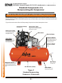
Information Bulletin IFB-01
March ‘07
…
Devair
Automotive
and Industrial
Air Compressor Units
...
Compressors,
Unit Sizing,
On-Site Layout,
And
Compressed Air Systems
...
This booklet is primarily geared to
assist both Distributors and
Customers in determining air
demands in a shop, and designing
a compressed air system to suit.
It provides general information on
compressed air, Air Compressor
Units, Refrigerated Air Dryers, Air
Line Filters, and general
requirements to make the various
components operate as designed.
Proper sizing, environment, and
maintenance are key to a long and
trouble-free compressed air
system life.
Distributed by:
If you require assistance, contact your local Devair Distributor or Authorized Service Centre. If you wish to
contact Devair directly or need to locate
your closest
reach us at :
CENTRAIR
AirDistributor,
Systemsplease
& Supplies
Phone:
Fax:
(705) 728-5657
(800) 561-1663
Phone: 705-722-5747
Website:
[email protected]
Email:
Fax: 705-722-5458
www.devair-compressors.com
www.centrair.ca
[email protected]
Information Bulletin IFB-01
For Sales & Service contact:
March ‘07
CENTRAIR Air Systems & Supplies 705-722-5747 [email protected] www.centrair.ca
Table of Contents
Contents
Page
1
2
General Information:
Introduction .......................................................................................
General Definitions ............................................................................
3
4
Air Compressors:
Types of Compressor Units Available ................................................
Single Stage' versus 'Two Stage' ......................................................
Standard Components of a Compressor ...........................................
Air Compressor Unit Sizing ...............................................................
Additional Info Required Before Quoting ...........................................
Installation - Mechanical ....................................................................
Installation - Electrical .......................................................................
Start-Up Procedures .........................................................................
Preventative Maintenance .................................................................
6
7
8
9
11
13
15
16
17
Refrigerated Air Dryers:
Purpose of a Refrigerated Air Dryer ..................................................
Available Refrigerated Air Dryers ......................................................
Installation - Mechanical ....................................................................
Installation - Electrical .......................................................................
18
19
21
22
Air Line Filters:
Why do I need Filtration in my Comp’d Air System? ........................
What Type of Filters are Available .....................................................
23
23
Compressed Air Systems:
Is there a ‘Rhyme or Reason’ to System Design? .............................
A Typical Air Piping System ..............................................................
25
26
Table of Contents
Front Page ..............................................................................................
Table of Contents ....................................................................................
-2-
For Sales & Service contact:
Information Bulletin IFB-01
CENTRAIR Air Systems & Supplies 705-722-5747 [email protected] www.centrair.ca
March ‘07
Introduction
Why Com
Why Compressed Air ?
Compressed air is a very widely used form of power, second only to electrical power. (A third form of power that is very
popular is hydraulic.) When a suitable and properly sized compressed air system is used, compressed air has many
benefits over other forms of power.
Why choose compressed air over electrical or hydraulic power? There are several advantages of compressed air and
compressed air systems. These include:
A) compressed air is clean and safe, posing no electric shock or fire hazard.
B) air tools run relatively cooler, as they do not generate heat while operating.
C) air tools are relatively light (having a high power to weight ratio), therefore contributing to less worker
fatigue and strain.
D) air tools generally have variable speed and torque controls.
To follow is a brief comparison of each. (Though this by no means is a complete listing, it reflects what we feel to be the
major points.)
Type:
Compressed Air
Safety:
R e d u c e s t h e d a n g e r o f May cause shocks or sparks,
electrical shock or fire hazard. resulting in personnel and
This is critical in some workplace safety issues.
applications such as painting
and mining.
Without expensive fire
retardant fluids being used,
exposure to fire or high
temperatures may create fire
hazards. Any leaks may result
in contamination
Costs:
A single air source in a More costly due to complicated
compressed air system allows componentry.
for many separate systems.
Also, as there are fewer
moving parts and because of
their simplicity in design, air
tools provide low cost
operation and maintenance.
A hydraulic system may be
complicated and costly when
compared to a compressed air
system.
Flexibility:
Portable Compressors can be Limited to areas where
used where other power electrical power is available.
sources are not available ie
gas or diesel powered Units..
Hydraulic systems are
somewhat more complicated
with regards to initial
installation, and the frequent
changing of tools is
cumbersome.
-3-
Hydraulic
General Information
Electric
For Sales & Service contact:
Information Bulletin IFB-01
CENTRAIR Air Systems & Supplies 705-722-5747 [email protected] www.centrair.ca
March ‘07
General Definitions
To follow are basic terms and concepts that are used throughout this booklet. These are helpful in that they give a
general understanding of compressed air.
What is atmospheric Pressure?
The air we breath, and that which surrounds the earth, has a weight associated with it. 'Atmospheric pressure' is a
term that relates the weight of the air (ultimately the weight of the atmosphere) to a particular area on the earth's
surface.
Area can generally be defined as a tract with both length and width. For arguments sake, lets use 1 inch long by 1 inch
wide. In this example, the area of a tract 1" Long x 1" Wide is 1 square inch.
Now, the air we breath (the atmosphere) puts a weight of 14.7
pounds on every square inch of the earth's surface (at sea level.
We'll deal with other elevations in the next paragraph.).(We didn't
just decide this; it's one of the many Laws of Physics.) In other
words, the 'atmospheric pressure' is 14.7 pounds per square inch
at sea level, or more simply put, 14.7 psi. See Figure 1.
The figure of 14.7 pounds per square inch is the atmospheric
pressure at sea level only. As you increase in altitude, the density of
the air becomes less, and therefore the atmospheric pressure also
becomes less. The actual pressure drop per 1000 feet in elevation
is about 1/2 psi. For example, at 6000 feet above sea level, the
atmospheric pressure will be 11.7 psi.
Due to the lower density and pressure at higher altitudes,
Compressor output is also affected. A good rule of thumb is that air
delivery is reduced by approximately 3% for every 1000 feet in
elevation above sea level.
14.7 lb
1"
1”
'Figure 1'
Atmospheric Pressure
(At Sea Level)
General Information
What is ‘gauge pressure’?
Gauges found on Compressor Units simply measure the pressure of the air
inside the Air Receiver above atmospheric pressure.This is commonly
termed 'gauge pressure' or 'psig'. When disconnected from a Unit, a gauge
will read '0 psi'.
A pressure gauge reading 175 psi simply indicates that the air pressure at
that particular point is 175 psi above atmospheric.
Though not commonly used, 'absolute pressure' (psia) is the addition of
both the gauge pressure and atmospheric pressure. In our example above:
psia = gauge pressure +
=
175 psig
+
=
189.7 psia
atmosp. pressure
14.7 psi
'Figure 2’
-4-
For Sales & Service contact:
Information Bulletin IFB-01
CENTRAIR Air Systems & Supplies 705-722-5747 [email protected] www.centrair.ca
March ‘07
General Definitions (cont'd)
What is Compressed Air ?
'Compressed air' is atmospheric air that has been forced into a volume smaller than it normally occupies.
At an air pressure above that of atmospheric pressure, the compressed air will always want to return to it's normal,
uncompressed state. It is this process that enables the compressed air to do work. This is similar to a spring, wanting
to return to it’s shape at rest.
In dealing with air volume, we must have a unit of measure that is easily recognizable. The standard measure of air
volume is 'Standard Cubic Feet'. The amount of volume used in a given period of time is generally measured in
'Standard Cubic Feet per Minute', or 'SCFM' for short.
Compressed air, as a whole, is generally measured as a volume of air dispensed over a period of time (CFM), and at a
certain pressure (psi). An example: a Compressor Unit may provide 18 CFM @ 150 psi.
‘Figure 3’ shows the effect that compressing one cubic foot of air at 0 psi has when compressed to 75 psi. This figures
shows that as the pressure of air increases, the volume decreases. At 75 psi, the volume of air is roughly 1/6 of that at 0
psi.
1'
1 Standard
Cubic Foot
of Air
@ 0 psi
1'
1 Standard
Cubic Foot
of Air
@ 75 psi
1'
1'
1'
2”
Air at Atmospheric Pressure
Air at an Elevated Pressure
(0 psig)
(75 psig)
'Figure 3’
Should the ambient temperature rise above 68°F, there will be a loss of air delivery equivalent to 2% for every 10°F
increase in temperature.
Are there any ‘by-products’ in compressing air?
Typically, compressing air yields the discharge of both heat and moisture. The greater the air volume compressed,
and the higher the pressure, the greater the heat generated. Moisture is simply caused by the inability of air to hold
moisture as it's pressure increases.
With proper guidance, as dealt with later in this booklet, heat and moisture need not be a concern.
-5-
General Information
In order that Air Compressors are manufactured and and tested in a uniform manner within the industry, testing and
related data and efficiencies are made at what is termed ‘Standard Air’. ‘Standard Air’ is considered to be air at a
temperature of 68°F, atmospheric pressure of 14.7 psi, and a relative humidity of 36%.
Information Bulletin IFB-01
For Sales & Service contact:
March ‘07
CENTRAIR Air Systems & Supplies 705-722-5747 [email protected] www.centrair.ca
Types of Compressor Units Available
There is a wide variety of Air Compressor Units available, Units used for anything from pumping up bicycle tires
periodically to operating large and expensive industrial machinery 24 hours per day. As there is such a variation of
uses and demands for compressed air, there are also Compressor Units suitable for each particular use.
Compressor Units are available in various configurations, each configuration being fairly unique based on
Compressor volume, pressure, and HorsePower. To follow is a brief description of some of the more common Unit
configurations.
What
Whatare
are the
the more common
common types
types of
of Air
Units
Compressors?
used ?
’Light Duty’ Oilless Type
* generally small, portable hand held, electrically driven Units
* used for 'household' applications, hobbyists
* oil free operation, so no oil downstream
* not moisture free
* generally run constantly while connected to power
* air delivery is limited from about 1 to 3 CFM
* air pressures are in the 30 to 40 psi range
* inexpensively priced, widely available, very little maintenance required
Reciprocating Type
* though available in portable Units, the majority of the larger Units are stationary
* used for 'household' (portables), automotive, and industrial applications
* generally use an oil lubricated Compressor Pump, so oil downstream is a consideration
* generally run intermittently (ie. not 'on' continuously)
* air delivery generally limited to approximately 125 CFM(typically a 30 HP Unit)
* air pressure is 150 to 175 psi maximum
* moderately priced, automotive/industrial Units available through select distribution, regular
maintenance required
Air Compressors
Rotary Screw Type
* generally available as stationary Units, though some portable Units are also available
* generally used in industrial applications, and those where great volumes of air are required, on an almost
continuous basis
* generally oil lubricated Compressor Pump (Air End)
* air delivery available to several thousands of CFM
* typical Units have a maximum air pressure of 120 psi, though they can go as high as 200 psi
* relatively expensive to purchase, available through select distribution, regular maintenance is critical (by
competent service company, and though somewhat more expensive than reciprocating Units,
maintenance is less frequent)
Though this is by no means a complete listing of all types of Compressors, it does note the major Units available. For
intermittent applications below 30 HP, the most commonly used Unit is the Reciprocating Compressor Unit due to its
moderate pricing, relative simplicity, and substantial performance characteristics.
-6-
Information Bulletin IFB-01
For Sales & Service contact:
March ‘07
CENTRAIR Air Systems & Supplies 705-722-5747 [email protected] www.centrair.ca
'Single Stage' versus 'Two Stage’
Reciprocating Units
Reciprocating Compressor Units are further classified as either Single Stage or Two Stage. These classifications deal
only with the Air Compressor Pump, and are a method of describing how the air is processed and brought from
atmospheric to maximum pressure.
What
Whatare
is athe
‘Single
moreStage’
common
Pump?
types of Units used ?
A 'Single Stage' Pump is a Pump in which one or more Cylinders brings the
air from atmospheric to maximum pressure in a single stroke of the Piston. In
a Pump where there is more than one Piston, the Pistons are the same size.
Typically, Single stage Pumps can produce air pressures to a maximum of
125 psi, and are therefore limited in their use.
‘Figure 4' shows a typical 'Single Stage' Pump. Though a One Cylinder Pump
is shown, they are not limited to that (one Cylinder), as noted above.
'Figure 4’
What
Whatare
is athe
‘Two
more
Stage’
common
Pump?
types of Units used ?
High Pressure Piston
Low Pressure Piston
During the first stage, the air enters the larger (or Low
Pressure) Cylinder, where it is compressed to approximately
50 psi. The air then travels through a cooling tube to the
smaller (or High Pressure) Cylinder (the second stage),
where it is further compressed to maximum pressure. Two
stage Pumps can generally produce air pressures to a
maximum of 175 psi to 200 psi, and are therefore more
suitable to automotive / industrial applications.
'Figure 5’ shows a typical 'Two Stage' Pump, indicating the
difference in the sizes between the first stage (Low Pressure)
Cylinder / Piston and the second stage (High Pressure)
Cylinder / Piston.
Two stage Pump may have more than two Cylinders and
Pistons.
'Figure 5’
-7-
Air Compressors
A 'Two Stage' Pump is a Pump in which two
Cylinders/Pistons bring the air from atmospheric to
maximum pressure. The Cylinders/Pistons consist of one
large Piston (also known as the Low Pressure)and one
smaller one (known as the High Pressure).
'Figure 4’
For Sales & Service contact:
Information Bulletin IFB-01
CENTRAIR Air Systems & Supplies 705-722-5747 [email protected] www.centrair.ca
March ‘07
Standard Components of a
Reciprocating Air Compressor
What are the standard Parts of a Reciprocating Compressor?
A standard Reciprocating Compressor, in both the vertical and horizontal format, generally consists of a Pump, an Air
Receiver (built in accordance with ASME requirements), an Electric Motor, and a variety of associated electrical and
pneumatic Controls.
'Figure 6’ shows the various Parts of a Reciprocating Compressor, and a brief description of each.
Compressor Pump
Intercooler Tube
Compresses the air
This Tube cools the compressed air while
leading it from the low pressure Cylinder to
the high pressure Cylinder
Aftercooler Tube
This Tube leads the compressed
air to the Air Receiver while
allowing the air to cool
Belt Guard
Electric Motor
Pressure Switch
Check Valve
A pneumatically operated electric
Switch for starting and stopping the
Unit at predetermined minimum
and maximum pressures
One way Valve that allows air
to enter the Tank, but prevents
the air from flowing back into
the Compressor Pump
Pressure Gauge
Air Compressors
Gauge reflects current Tank
pressure
Ball Valve
Magnetic Starter
An electrically operated device which
receives a signal from the Pressure
Switch and allows power to flow to the
Motor.
Discharge/outlet
Air Receiver (Tank)
Drain Valve
Allows the operator to drain
the moisture from the Tank
'Figure 6’
Standard Reciprocating
Compressor Components
-8-
Information Bulletin IFB-01
For Sales & Service contact:
March ‘07
CENTRAIR Air Systems & Supplies 705-722-5747 [email protected] www.centrair.ca
Air Compressor Unit Sizing Guide
How do I select a Unit to suit my Customer’s needs ?
In order to provide a customer with a meaningful quotation that reflects a Compressor Unit that will handle their
compressed air requirements, one must first determine what air volumes and pressures are required on site, and then
choose a Unit to suit. To follow is a 'Six Step' Method in selecting the right sized Compressor for your customer's air
requirements.
Six Steps to Assist in Selecting the Right Size Compressor
Separate the Equipment into two categories.
4.
This should be based on both Continuous and Intermittent
use. Make a list of all the air tools and equipment intended for
use with the Compressor. Hand triggered tools (air impact
wrenches, nailers, etc.) are generally considered Intermittent.
Air motors or sand blasters, on the other hand, create a
steady demand on the Compressor all the while they are
operating, and can therefore be considered Continuous.
2.
Determine the total CFM requirements for each
type of equipment being used.
Using 'Chart 1' on 'Page 10', list the free air consumption for
the items in each category and multiply the CFM required for
each tool by the number of similar tools to be used.
Example: If there are two different stations, each using a 5"
body sander, the total consumption would be
2 sanders x 5 CFM each = 10 CFM
3.
Total the CFM for the items in both the Intermittent
and Continuous categories.
Qty:
Total:
1/2" Impact
4
1
4
Body Sander
5
2
10
10
1
10
Total Consumption:
The Total Consumption for the Compressor would then be as
follows:
9.6 CFM (Int.) + 7.0 CFM (Cont) = 16.6 CFM
Note:
If a number of intermittent air tools are to be used
simultaneously in a continual demand situation, replace the
40% (.40) in the formula with a figure that better represents
the actual percentage of operation, ie 60% (.60) or 70% (.70).
6.
Divide the ‘Total Consumption for the Compressor’
as determined in ‘4’ by .75 .
CFM:
Qty:
3/32 Sand Blaster
7
1
Apply the total CFM requirement as calculated in '5’
to the Devair Compressor units as noted in 'Chart
2' on Page 10.
Ensure that the maximum output pressure of the Compressor
Unit is sufficient to handle any of the tools used. In an instance
where two tools are used by the same operator, but never at
the same time, list only the tool with the higher air
consumption.
24 CFM
Continuous Use:
Item:
Total Consumption:
For continuous use, you must use the full value of the various
tools.
In order to allow the Compressor to cool properly, we must
allow for downtime between cycles. The dividing of the Total
Consumption by .75 allows for this.
CFM:
Spray Gun
For Intermittent use, the total consumption is generally
multiplied by a factor of .40 to reflect an approximate 40%
intermittent use of the various tools. Using our example in '3',
24 CFM x .40 = 9.6 CFM
5.
Example:
Intermittent Use:
Item:
Combine the Total Consumption for Intermittent
and Continuous Use.
Adjusting the formula to suit individual shop requirements is
reliant on a first-hand knowledge of the total shop operation. If
care is taken to include all air consuming equipment, a good
assessment of the total consumption can be made.
Total:
7
7 CFM
-9-
Air Compressors
1.
For Sales & Service contact:
Information Bulletin IFB-01
CENTRAIR Air Systems & Supplies 705-722-5747 [email protected] www.centrair.ca
March ‘07
Air Compressor Unit Sizing Guide (cont'd)
Chart # 1
Automotive and Industrial Type Tools and Equipment
Air Operated Equipment
Air Filter Cleaner
Air Motor Paint Pot
Airless Pumps
Automatic Drill
Bead Breaker
Body Polisher
Body Sander 5"
Body sander 7"
Body Sander Heavy Duty
Brake Tester
Burring Tool
Bushing Tool
Car Rocker
Car Washer
Carbon Remover
Carving Tool (Stone)
Circular Saw 8"
Circular Saw 12"
Compression Riveter
Cylinder Hoist
Drill 1/16" to 3/8"
Drill 3/8" to 5/8"
Duster Gun (Blow Gun)
Engine Cleaner
Filing and Sawing Machine
Floor Jack
Grease Gun (High Pressure)
Grinder (Die, Small)
Grinder (Die, Medium)
Grinder (Horizontal 2")
Grinder (Horizontal 4" and 6”)
Grinder (Horizontal 8”)
Grinder (Vertical & Sander 5")
Grinder (Vertical & Sander 7")
Grinder (Vertical & Sander 9")
Hammer, Air
Hammer, Chipper
Hammer, Fender
Hammer, Riveter
Hammer, Scaler
Hammer, Tire
Pressure
Range (psi)
70-100
70-100
100
70-100
70-100
70-100
70-100
70-100
70-100
70-100
70-100
70-100
120-150
70-100
70-100
70-100
70-100
70-100
70-100
70-100
70-100
70-100
70-100
70-100
70-100
100
120-150
70-100
70-100
70-100
70-100
70-100
70-100
70-100
70-100
70-100
70-100
70-100
70-100
70-100
70-100
Average Air
Cons. (CFM)
Air Operated Equipment
Hydraulic Lift **
Impact Wrench 1/4"
Impact Wrench 3/8"
Impact Wrench 1/2"
Impact Wrench 5/8"
Impact Wrench 3/4"
Impact Wrench 1"
Impact Wrench 1-1/4"
Nutsetter - up to 3/8"
Nutsetter - up to 3/4"
Paint Stirrer
Panel Cutter
Pneumatic Door
Pneumatic Jack
Pneumatic Nailers & Staplers
Radiator Tester
Rammer
Ratchet 1/2"
Retread Mold
Rim Stripper
Rivet Buster
Sandblaster 3/32" Nozzle
Sandblaster 1/8" Nozzle
Sandblaster 5/32" Nozzle
Sandblaster 3/16" Nozzle
Screwdriver #2 to #6 Screw
Screwdriver #6 to 5/16" Screw
Spark Plug Cleaner
Spark Plug Tester
Spray Gun - Auto / Refinishing
Spray Gun - Paint / Production
Spray Gun - Paint / Touch up
Spray Gun - Undercoating
Spring Oiler
Tapper - up to 3/8"
Tire Changer
Tire Inflation Line
Tire Spreader
Trans. & Differential Flusher
Vacuum Cleaner
3
10-14
8-24
6
8
2-8
4-6
9
11
3.5
4-5
15-25
5.8
8.5
3
10-15
15.8
23.8
1
1.3
4
7
2.5-10
5
3.5
6
3
5.3
8.4
7
21
28
12.3
21
24.5
3.5
7
21
15
4
18
Pressure
Range (psi)
145-175
70-100
70-100
70-100
70-100
70-100
70-100
70-100
70-100
70-100
70-100
70-100
120-150
120-150
100
70-100
70-100
70-100
70-100
120-150
10-100
80
80
80
80
70-100
70-100
70-100
70-100
75
50-75
30-60
70-100
70-100
70-100
120-150
125-150
120-150
70-100
120-150
Average Air
Cons. (CFM)
5.25
2.5
3
4
6
10
12
19.2
8.4
10.5
15
13
2
0.5
6
1
5-7
5
5
6
35
7
15
25
40
4.2
8.4
5
0.5
8.5-12
8.5-15
3
19
4
3
1
1.5
1
3
6.5
** For 8000 lb capacity; Add 0.65 CFM for each additional 1000 lb capacity.
Note: 1) The above figures are estimates only. Please consult your particular equipment manufacturer for current air consumption figures.
2) Air Tool manufacturers generally list their tool air consumption in terms of ‘free air delivery’, ie air simply flowing through the tool with no load.
Under loading, air consumption may vary drastically from published values. Consult the equipment manufacturer for realistic consumption values.
Chart # 2
Standard Devair Air Compressor Units
Air Compressors
Req'd
Press.
100 psi
125 psi
Req'd
Capacity
Unit
HP
Req'd
Press.
Tank Size
(US Gal)
Req'd
Capacity
Unit
HP
2.0 CFM
½ HP
19.8 CFM
5 HP
3.0 CFM
3/4 HP
25.9 CFM
7-1/2 HP
3.9 CFM
1.0 HP
36.8 CFM
10 HP
5.6 CFM
1-1/2 HP
52.1 CFM
15 HP
5.6 CFM
2 HP
7.0 CFM
2 HP
11.4 CFM
3 HP
30 Gallon
Horizontal
150 psi
80 Gallon
Horizontal
Tank Size
(US Gal)
80 Gallon
Horiz or Vert.
120 Gallon
Horiz or Vert.
87.0 CFM
25 HP
99.9 CFM
30 HP
240 Gallon
Horizontal
25.9 CFM
13 HP Gas
30 Gal Horiz.
Note: Though the 5 to 30 HP electric Compressor Units are noted as being 150 psi, they are pre-set at the factory at this pressure. It is possible to run the Units at
175 psi by simply adjusting the Pressure Switch.
- 10 -
For Sales & Service contact:
Information Bulletin IFB-01
CENTRAIR Air Systems & Supplies 705-722-5747 [email protected] www.centrair.ca
March ‘07
Additional Info Required Before Quoting
WhatElectrics
other information do I need to know before quoting ?
On-Site
On-Site Electrics
Air Compressors are available in a variety of electrical voltages, and in both single and three phase Units. Before
providing a quotation to your customer, ensure that you know the on-site electrics, and choose the correct
Compressor to suit.
Please find on 'Page 12’ electrical specifications pertinent to the standard Devair line of Compressor Units. It notes
information required to ensure that a customers site is capable of operating the Unit in a safe and correct manner.
Helpful Tips to Remember Concerning Unit Electrics
1) Though single phase Units are available, use three phase Units when on-site electrics allow. Single phase
Units require much more power (and are therefore more costly) to both start and operate.
2) Single phase Units are available only in 5 HP and 7-1/2 HP configurations. Should your customer have
need of a larger Unit (but only has single phase power available), provide multiples of the 5 HP and 7-1/2 HP
Units.
3) Over the course of a day, on-site voltage may vary depending on demand. Motor manufacturers are aware of
this, and allow a variance of the nameplate Motor voltage +/- 10%.
Example:
Nameplate voltage:
Maximum allowable:
Minimum allowable:
460 volt
506 volt (460 + 10%)
414 volt (460 - 10%)
When choosing a suitable Compressor Unit for certain on-site electrics, ensure that the building voltage (at
the Unit) is within the +/- 10% of the Motor voltage variance as noted above.
Example:
Note:
On-site voltage:
Suitable Motor:
208-60-3
200 volt
(208 volt, 60 cycle, 3 phase)
(200 + 10% = 220 max allowable)
Though a 230 Volt Motor will handle the 208 on-site electrics, should the building voltage drop
below 207 volts (230 - 10%), premature Motor failure could occur. Use a 200 Volt Motor.
Premature Motor failure due to incorrect on-site voltage (in relation to Motor voltage) is not covered by the
manufacturers Warranty.
Should you have any questions concerning electrical componentry required, local Codes or Regulations, etc.,
contact your Electrician, local governing authority, or the Compressor manufacturer.
5) All Devair Heavy Duty Cast Iron Compressor Units require a Magnet Starter to provide overload
protection to the Electric Motor. The Starter may be purchased with the Unit or separately.
6) Though every attempt is made to ensure that Compressor Units are manufactured to the governing
standards, any inspections required on site by a local authority are done at the customer's expense.
- 11 -
Air Compressors
4) All electrical work should be carried out by a competent Electrician, and done in such a manner that it
meets all applicable Codes and Regulations.
For Sales & Service contact:
Information Bulletin IFB-01
CENTRAIR Air Systems & Supplies 705-722-5747 [email protected] www.centrair.ca
March ‘07
Additional Info Required Before Quoting (cont’d)
WhatElectrics
electrical loading will the Unit put on the building ?
On-Site
As noted on Page 11, Compressor Units are available in a variety of electrical configurations. Noted below are standard Devair
Compressor Unit configurations with their electrical data. Please be advised that this information is correct at the time of publishing
this booklet. It may vary slightly, dependent on manufacturer and/or supplier design and specification changes.
Unit
HP
Unit Model
Number
½
Unit Model
Number
Dependent on
Configuration
3/4
1
1-1/2
2
3
Unit Model
Number
Dependent on
Configuration
Unit Model
Number
Dependent on
Configuration
Unit Model
Number
Dependent on
Configuration
Unit Model
Number
Dependent on
Configuration
Unit Model
Number
Dependent on
Configuration
Phase
Single
Three
Single
Three
Single
Three
Single
Three
Single
Three
Single
Three
Single
5
Unit Model
Number
Dependent on
Configuration
7-1/2
Unit Model
Number
Dependent on
Configuration
10
Unit Model
Number
Dependent on
Configuration
Three
Unit Model
Number
Dependent on
Configuration
Three
VAVC-5000
Three
25
VAY-5081
Three
30
VAY-5081
Three
Three
Air Compressors
Single
Three
15
Voltage
Motor Amps
(Nameplate)
115
230
208/230
460
575
115
230
208/230
460
575
115
230
208/230
460
575
115
230
208/230
460
575
115
230
208/230
460
575
115
230
208/230
460
575
230
200
230
460
575
230
200
230
460
575
200
230
460
575
200
230
460
575
200
230
460
575
200
230
460
575
200
230
460
575
8.4
4.2
2.0
1.0
0.8
10.2
5.1
3.0
1.5
1.2
13.4
6.7
2.8
1.4
1.1
18.0
9.0
4.2
2.1
1.7
20.4
10.2
5.6
2.8
2.2
32.0
16.0
8.0
4.0
3.2
23.0
15.2
13.2
6.6
5.3
31.0
23.0
21.6
10.8
8.0
31.0
28.0
14.0
11.0
43.0
37.0
18.5
14.7
43.0
38.8
19.4
15.5
69.0
62.0
31.0
23.8
81.0
72.0
36.0
28.0
- 12 -
Max. Allow.
Amp Draw
9.6
4.8
2.3
1.1
0.9
11.7
5.8
3.4
1.7
1.3
15.4
7.7
3.2
1.6
1.2
20.7
10.3
4.8
2.4
1.9
23.4
11.7
6.4
3.2
2.5
36.8
18.4
9.2
4.6
3.6
26.4
17.4
15.1
7.6
6.1
35.6
26.4
24.8
12.4
9.2
35.6
32.2
16.1
12.6
49.4
42.5
21.2
16.9
49.4
44.6
22.3
17.8
79.3
71.3
35.6
27.3
93.1
82.8
41.4
32.2
Amps Req'd
@ Start-up
140
96
94
47
38
184
171
150
75
49
202
180
90
72
285
242
121
97
313
272
136
109
446
384
192
151
535
488
244
177
For Sales & Service contact:
Information Bulletin IFB-01
CENTRAIR Air Systems & Supplies 705-722-5747 [email protected] www.centrair.ca
March ‘07
Installation - Mechanical
There are many factors which are important in the correct and safe location of the Compressor Unit. These factors
include both environmental conditions as well as accessories that you may purchase.
Where
should I locate the Compressor Unit ?
On-Site
Electrics
The drawing below (Figure 6) shows the recommended space requirement of a good installation. A horizontal
Compressor Unit is shown.
18” (0.5 m)
minimum
Building Wall,
etc.
BeltGuard
Compressor
‘Figure 6’
Locate the Unit in a cool, dry, well ventilated area.
The Compressor Units perform at their optimum capabilities when in an environment of temperature 68° F,
atmospheric pressure of 14.7 psi, and relative humidity of 36%. Though this is not possible in a normal working
environment, there are several key things that the Customer can do to ensure that the Compressor works as designed.
These are as follows:
* Place the Unit in a cooler part of the shop. Hot environments may lead to premature Pump failure and excessive
oil bypassing.
* The Unit should be a minimum of 18” from a building wall or nearest obstruction. This allows maximum air flow
around and over the Unit, thereby having a maximum cooling affect.
* As the Motor provided on the Compressor is a General Purpose (GP), Open Drip Proof (ODP) Motor, the Unit
should be located in a clean area. Dust could find its way into the Motor and cause premature failure. Also,
dust/dirt on the Compressor Pump will cause higher operating temperatures and could result in premature failure.
* Locating the Unit in a separate room, away from the general operations of the shop, will provide a more suitable
environment, as well as containing the noise from the Compressor.
- 13 -
Air Compressors
* The Area in which the Unit is placed should be relatively dry. Excessive humidity will cause a buildup of moisture
in the Pump (thereby causing possible premature deterioration) as well as water in the oil.
Information Bulletin IFB-01
For Sales & Service contact:
March ‘07
CENTRAIR Air Systems & Supplies 705-722-5747 [email protected] www.centrair.ca
Installation - Mechanical (cont’d)
WhatElectrics
Accessories should be purchased with the Unit ?
On-Site
Though there are various Accessories that are available for your Compressor Unit, not all are necessary for its safe
and correct operation. To follow is a breakdown of what Devair would consider to be both ‘Necessary Accessories’ and
‘Optional Accessories’.
Necessary Accessories.
Vibration Isolator Pads.
The Vibration Pads are used to absorb any undue vibration caused by the Unit,
allow the Unit to run marginally quieter, and allow for any irregularities in the shop
floor.
Vibration Pads
Flexible Connector.
A Flexible Connector should be used in the air line directly downstream from the Unit. The Flex Connector protects the building
piping from any undue vibration caused by the Unit, as well as
allowing for any mis-alignment between the Unit and the piping.
Flexible Connector
Optional Accessories.
Automatic Tank Drains.
The Compressor Tank must be drained on a daily basis, as per
the manufacturers instructions. A buildup of water in the Tank will
both limit the Compressor performance, and potentially cause
moisture in your air lines as well as causing the Tank to
deteriorate prematurely. An Automatic Drain, either Pneumatic or
Electronic, may be purchased to ensure that the draining is done
on a regular basis.
Pneumatic
Electronic
Automatic Tank Drains
Air Compressors
Remote Air Intake Kits.
A Remote Air Intake Kit allows cooler, outside air to be drawn into the Air
Compressor Unit. This ensures that the Unit uses relatively clean, cool
air, thereby lowering the Compressor operating temperature and
allowing it to operate more efficiently.
Remote Air Intake
Low Oil Safety Monitors.
The Low Oil Safety Monitor automatically shuts the Compressor Unit off
when the oil level in the Pump has gone below an acceptable level.
FU
LL
LOW
Devair
Low Oil Safety Monitor
- 14 -
Information Bulletin IFB-01
For Sales & Service contact:
March ‘07
CENTRAIR Air Systems & Supplies 705-722-5747 [email protected] www.centrair.ca
Installation - Electrical
How do
I hook the Unit up to my building ?
On-Site
Electrics
It is responsibility of the Compressor owner to ensure
that the Compressor Unit is electrically connected in a
safe and correct manner. Any electrical work should be
carried out by a competent Electrician, and be done is
such a way that it meets all applicable Codes and
Regulations.
A Magnetic Starter, as shown below, is not required on the
Pit Boss line of Units, but must be an integral part of the
Heavy Duty Cast Iron Compressor Unit circuit as it
provides overload protection to the Electric Motor. A
Magnetic Starter can be purchased separate from the Unit,
or factory-mounted at time of manufacture.
Failure to connect the Compressor
correctly to your building's electrical
services may result in serious personal
injury, or damage to equipment.
Main Fuse Box
L1
Fused Disconnect
or Circuit Breaker
L2
L3
Magnetic Starter
C
Motor
‘Figure 7’
Typical Pictoral Representation
of Compressor Installation
‘Figure 8’
Typical Magnetic Starter Wiring
(Subject to Local Codes & Authorities)
- 15 -
Air Compressors
Pressure
Switch
Information Bulletin IFB-01
For Sales & Service contact:
March ‘07
CENTRAIR Air Systems & Supplies 705-722-5747 [email protected] www.centrair.ca
Start-Up Procedures
WhatElectrics
is involved in the ‘initial start-up’ of the Unit ?
On-Site
The following is a guideline which the Customer must follow in the correct initial start-up of their new Compressor
Unit. Please pay close attention to the various Notes, Cautions, and Warnings.
1. Please note that, under normal operating conditions, the Compressor Unit
will operate intermittently. The Unit starts/stops without warning.
2. Shut off all power to the Air Compressor Unit before attempting any repair
or maintenance.
NOTE
Do not attempt to operate the Unit without first
checking whether there is Oil in the Pump. Add
Oil as required. Serious damage may result
from use, however limited, without Oil.
5) Open the Compressor's Ball Valve, and start the
Unit. Ensure that the air is escaping to
atmosphere. Allow the Unit to operate in this
fashion for approximately 30 minutes. This
lubricates the Pistons, Bearings, and all internal
surfaces.
1) Remove the Oil Filler Plug, and ensure that there
is Oil in the Crankcase. Refer to the "Lubrication"
section in the pertinent Compressor Unit manual
for the proper type and level of Oil.
Do not place any materials on or against the
Belt Guard, or the Compressor Unit as a whole.
Placing materials there will limit the cooling of
the Compressor, and could lead to premature
failure.
2) Replace the Oil Filler Plug, and tighten as
required. Refer to Compressor Unit manual.
3) Do a visual inspection of the Unit, and e n s u r e
that all Bolt heads are sufficiently tightened. This
must be done, as some fasteners may become
loose in transit.
4) Turn the Compressor 'On' momentarily by
positioning the Fused Disconnect in the 'On'
position. Ensure that the Flywheel is turning in
the correct direction. Pit Boss Units rotate only
one way. For Heavy Duty Units, see "Pump
Rotation" (page 10) in Unit manual.
Air Compressors
NOTE
On Compressors with 3 phase power, adjust
the wiring at the Motor terminals if the rotation
is incorrect. Refer to the wiring diagram on or in
the Motor terminal box.
NOTE
6) After having run the Compressor Unit for 30
minutes, close the Ball Valve, and allow the unit
to reach maximum operating pressure. Ensure
that the Compressor shuts down at the pre-set
maximum pressure, and the head pressure is
released through either the front of the Pump (the
CPR) or at the Pressure Switch.
7) Check the Compressor and Piping Systems for
air leaks, and correct as required.
8) Stop the Compressor, and check the Oil level in
the Crankcase. Add Oil as required.
During the first few days of operation, check the Unit periodically to ensure it is
running smoothly and the controls are operating properly. Should you notice any
areas of concern, contact your Devair Distributor or Authorized Service Centre.
- 16 -
Information Bulletin IFB-01
For Sales & Service contact:
March ‘07
CENTRAIR Air Systems & Supplies 705-722-5747 [email protected] www.centrair.ca
Preventative Maintenance Schedule
WhatElectrics
regular maintenance is required ?
On-Site
As with all pieces of equipment, a Compressor Unit must be serviced / maintained on a regular basis. If this is not
done, the Customer will experience unscheduled problems, perhaps leading to complete failure of the Unit. To
follow are general guidelines to follow. When purchased, your Unit may have varying requirements.
When servicing the Air Compressor, shut off all power to the Unit, and drain the Tank of air pressure. Always
replace the BeltGuard after adjusting the Belts or Pulleys.
To follow are general Maintenance guidelines based on an approximate Compressor usage of 40 hours
per week. If your usage varies from this, adjust accordingly. (Consult the literature that accompanies
your Compressor Unit for the exact Maintenance Schedule for your Unit.)
MAINTENANCE
NOTE
DAILY
It is the responsibility of the
compressor owner to ensure that a
regular Maintenance Schedule is
followed.
Drain moisture from tank
Check oil level and top
up if necessary
OIL
LEVEL
OIL
QUARTERLY
Change Oil & Filter
Order Maintenance Kit
OIL
OIL
Check condition and
alignment of Belt, Flywheel
and Motor Pulley
Check Safety Valve
PULL
TO
TEST
Check Pressure Switch
Unloader or CPR Unloader
to ensure Compressor Head
unloads whenever Motor
shuts down
Clean and/or blow off
Pump Fins and Motor
2000 Hour Maintenance
Though not noted on the "Maintenance"
label (shown at left) ,the Compressor
should have a more thorough Unit
overhaul every 2000 hours. (Based on a
40 hour work week, 2000 hours is roughly
once a year.) To follow are items that
should be included in this procedure.
Lubricate Motor Bearings.
CPR
PRESSURE
SWITCH
UNLOADER
CLEAN
THE
PUMP
Please consult operating manual included with your
Air Compressor for detailed maintenance information
- 17 -
Inspect and replace as necessary the
following:
Pump Valves
Check Valve(s)
Safety Valve(s)
Pressure Gauge
Belt(s)
Air Compressors
WEEKLY
Information Bulletin IFB-01
For Sales & Service contact:
March ‘07
CENTRAIR Air Systems & Supplies 705-722-5747 [email protected] www.centrair.ca
The Purpose of an Air Dryer
Why do
I need a Refrigerated Air Dryer ?
On-Site
Electrics
A Brief Physics Lesson.
Though not readily visible, water vapour is present in the atmosphere that we live in. When an Air Compressor is used
to increase the pressure of air from atmospheric to something higher, the increase in pressure tends to force the water
vapour to condense into water droplets. As there is a great deal of heat present in the compressing of the air, and the
warmer the air temperature the more moisture it can hold, the hotter compressed air leaves the Compressor Unit with
all the moisture present in a vapour state. In other words, the air has all the moisture in it still in vapour form, none of it
has changed to a liquid state.
As the compressed air travels through the compressed air system, and cools down to the ambient temperatures, the
water vapour held in the air begins to condense into liquid droplets inside the air lines. The temperature at which the
water vapour begins to form into liquid droplets is known as the ‘dew point’.
And What Will a Dryer do for Me ?
Air containing moisture may not be harmful to some industries, but it may be very harmful to others. Applications such
as the autobody refinish industry and HVAC installations are areas where moisture content is very critical, resulting in
inferior finishes or damaged controls and componentry.
With a Refrigerated Air Dryer, the compressed air is cooled down to a temperature at which the moisture content is
condensed into a liquid state. The Dryer then, by way of an internal Separator, discharges the liquid. The key to the
Refrigeration Unit is the ability to dry the air at a dew point temperature below the lowest temperature to which the
compressed air will be exposed.
With a properly sized and maintained Refrigerated Air Dryer, and coupled with suitable filtration, moisture at your point
of use will be non-existent.
How can I Justify the Expense ?
1. Tool maintenance will be reduced. Water, oil, and additional contaminants may cause tools to stick, jam, or clog.
2. Tool life will increase. Water washes away lubricants, causing excess wear and corrosion.
3. Air consumption will be reduced. More air is used when it contains water, oil, etc in order to blow out sludge. Also,
water will corrode the inside of the air lines.
Refrigerated Air Dryers
4. Production will be increased. Workers can use their tools immediately, as there is no need to purge water or
contaminants from the air lines.
5. Piping life is extended indefinitely as internal water corrosion is eliminated.
6. Production quality is improved and maintained there. Instruments, etc are sensitive to water and contaminants.
Poor air quality may cause poor product quality, increased rejects, and production shut-downs because of
malfunctioning controls and tools.
7. Spray paint production is boosted. Water on or under the paint surface will cause both blisters and paint runs,
requiring both refinishing and repainting.
8. Trap maintenance down-stream of your Refrigerated Air Dryer is almost eliminated. The only maintenance
required regularly is at the Dryer Separator.
9. New installations will not require pitched air lines, drop legs, traps, or drains.
- 18 -
Information Bulletin IFB-01
For Sales & Service contact:
March ‘07
CENTRAIR Air Systems & Supplies 705-722-5747 [email protected] www.centrair.ca
Available Refrigerated Air Dryers
WhatElectrics
types of Dryers are available through Devair ?
On-Site
Devair offers two varieties of Refrigerated Air Dryers, namely the ‘DRD Refrigerant Dryer’ series and the ‘PD
Prodry’ series. Though both series of Dryers provide dry compressed air to your point of use, there are some
noticeable differences between the two Units.
A Comparison of the Devair ‘ASD’ and ‘Prodry’ Series of Refrigerant Dryers.
‘HTD’ Series Refrigerant Dryer
Maximum Inlet Temperature
(The maximum allowable
temperature of compressed air
entering the Dryer inlet)
120°F (49°C)
180°F (83°C)
Suggested Length of Piping
Between Compressor Outlet
and Dryer Inlet
Approximately 20 Feet
Minimum of 3 to 4 Feet
Maximum Inlet Pressure
(The maximum allowable pressure
of compressed air entering the
Dryer inlet)
200 psig (13.8 Bar)
232 psig (16 Bar)
Controls Available
Unit controlled by Microprocessor
Digital ‘dew point’ Indicator
Some Unit parameters adjustable
Unit controlled by Microprocessor
Digital ‘dew point’ Indicator
Some Unit parameters adjustable
Initial ‘In-line’ Air Strainer
(Removes larger contaminants
from the compressed air before
entering the Dryer)
No
No
Internal Filter
High Efficiency Stainless Steel Baffles
guarantee a low pressure drop and smooth
operation
High Efficiency Stainless Steel Baffles
guarantee a low pressure drop and smooth
operation
Internal Auto Drain
(Drains moisture from Separator
Assy periodically)
Yes - Electronic Type
Yes - Electronic Type
Internal AfterCooler
No
Yes
Refrigerant Cycle Dew Point
33°F - 39°F (1°C - 4°C)
37°F (3°C)
- 19 -
Refrigerated Air Dryers
‘ASD’ Refrigerant Dryer
Information Bulletin IFB-01
For Sales & Service contact:
March ‘07
CENTRAIR Air Systems & Supplies 705-722-5747 [email protected] www.centrair.ca
Available Refrigerated Air Dryers
WhatElectrics
information should I know before ordering ?
On-Site
To follow is basic information concerning both the ‘ASD’ and ‘HTD’ Series of Devair Refrigerated Air Dryers. This
information is both required for ordering the correct Unit, as well as ensuring the Installer is aware of the mechanical
requirements.
‘ASD’ Series of Refrigerant Dryers.
Model
ASD15
Air Comp.
HorsePower
5 HP
SCFM
Electrics
Inlet/
Outlet
Width
Depth
Height
Weight
15
½” NPT
15.4”
18.1”
15.8”
64#
½” NPT
15.4”
18.1”
15.8”
66#
¾ ” NPT
17.3”
23.6”
21.6”
104#
¾” NPT
17.3”
23.6”
21.6”
110#
ASD30
7-1/2 HP
30
ASD40
10 HP
40
ASD60
15 HP
60
ASD100
25 HP
100
1-½” NPT
19.0”
32.1”
38.5”
198#
ASD150
30 HP
150
1-½” NPT
19.0”
32.1”
38.5”
216#
1-½” NPT
19.0”
32.1”
38.5”
232#
2-½” NPT
28.0”
57.0”
38.5”
353#
2-½” NPT
28.0”
57.0”
38.5”
420#
Width
Depth
Height
ASD200
200
ASD320
320
ASD400
400
115/60/1
230/60/1
230/60/3
‘HTD’ Series of Refrigerant Dryers.
Refrigerated Air Dryers
Model
Air Comp.
HorsePower
SCFM
HTD18
5 HP
18
HTD26
7.5 HP
26
Electrics
Inlet/
Outlet
Weight
¾” NPT
17-1/4”
23-7/8”
21-3/4”
80#
¾” NPT
14-3/8”
19-5/8”
26”
75#
115/60/1
HTD37
10 HP
37
¾” NPT
14-3/8”
19-5/8”
26”
80#
HTD52
15 HP
52
¾” NPT
14-3/8”
19-5/8”
26”
86#
Note: The models noted are available at the time of printing. Please contact Devair by phone or visit our
website at ‘www.devair-compressors.com’ for the most current models.
- 20 -
For Sales & Service contact:
Information Bulletin IFB-01
CENTRAIR Air Systems & Supplies 705-722-5747 [email protected] www.centrair.ca
March ‘07
Installation - Mechanical
Where
should I locate the Refrigerated Air Dryer ?
On-Site
Electrics
As with the Air Compressor Unit, the Refrigerated Air Dryer must be installed in an environment that allows for both it’s
correct and safe operation. To follow are some basic points in deciding where to install the Dryer.
* Place the Dryer in a cooler part of the shop. The refrigeration system requires relatively cool air to function at it’s
optimum. When placed in a very warm environment, the refrigeration system must work much harder to cool the air,
thus becoming less efficient.
* The Unit should not be located in a dusty environment. The interior of the Dryer Unit contains items which must
be kept clean to work efficiently. Any build-up of dust and debris will limit the operation of the Unit, and may cause
failure.
* Locating the Unit on a suitable pedestal will ensure that floor dust is not drawn into the Unit.
6”
To
Wall
12”
Min
3”
To
Wall
18”
Min
R
AIdry ASD
DVPRO
18”
Min
R
AIdry HTD
DVPRO
‘ASD’Series of Refrigerated
Air Dryers
To ensure that there is enough clearance in front of the
Unit for proper access, please allow a minimum of 24”
between the front of the Unit and any adjacent
obstructions.
- 21 -
‘HTD’Series of Refrigerated
Air Dryers
Refrigerated Air Dryers
12”
Min
Min
36”
Min
36”
To follow are suggested clearances around both the ‘ASD’ and ‘HTD’ Series of Devair Refrigerated Air Dryer Units.
For Sales & Service contact:
Information Bulletin IFB-01
CENTRAIR Air Systems & Supplies 705-722-5747 [email protected] www.centrair.ca
March ‘07
Installation - Electrical
How do
I connect the Dryer to power ?
On-Site
Electrics
The Devair Dryer Units are equipped with a suitable cord and plug to be installed in the appropriate electrical
receptacle of proper voltage.
To follow is a listing of the various Dryer Units and their electrical requirements. Please make note of the Full Load Amp
and/or Circuit Fuse requirements when installing the Unit, ensuring that the building circuit is suitable for the Dryer
Unit.
Do not, under any circumstances, modify the internal or external wiring of the Unit. Electrical modifications may cause
both electrical failure in the Unit, as well as void the manufacturers 1 (One) Year Limited Warranty.
‘HTD’ Series of Refrigerant Dryers.
‘ASD’ Series of Refrigerant Dryers.
Model
Electrics
Full Load
Amps
Model
ASD15
1.97
2.3
HTD18
ASD30
3.5
4.3
HTD26
4.58
6.25
4.58
6.25
ASD40
115/60/1
ASD60
ASD100
7.08
9.82
ASD150
5.84
7.87
6.78
8.98
10.3
13.7
3.69
4.93
ASD200
230/60/1
ASD320
ASD400
Refrigerated Air Dryers
Nominal
Amps
230/60/3
Electrics
Nominal
Amps
Full Load
Amps
4.23
5.24
2.6
3.5
HTD37
4.58
6.25
HTD52
4.58
6.25
115/60/1
As the Devair Refrigerated Air Dryer require electricity to operate, the Units must be installed in such a manner that
they comply with all applicable electrical codes.
Also, the Dryer Units are equipped with electrical enclosures not suitable or intended for installation in hazardous
environments.
As with all electrically operated devices, when performing any service work on the Unit, disconnect the Unit from the
power supply. Servicing or maintaining the Unit while connected to power could result in serious injury to personnel
and the Unit.
- 22 -
For Sales & Service contact:
Information Bulletin IFB-01
CENTRAIR Air Systems & Supplies 705-722-5747 [email protected] www.centrair.ca
March ‘07
Air Line Filtration
Why do
I need Filtration in my Compressed Air System ?
On-Site
Electrics
A compressed air system is typically contaminated with impurities which could ultimately cause serious problems
where clean air is critical. As noted in the section dealing with the Refrigerated Air Dryers, applications such as the the
autobody refinish industry and HVAC installations require compressed air that is free of contamination.
Impurities that can be found in a compressed air system may include solid particles, water droplets, and oil aerosols
and vapours. With suitable Air Filters in the system, and paying close attention to both the type and size (of Filters)
required, your Customer can obtain the air quality that their application demands.
Please be advised that in areas and applications where air quality is of great importance, suitable filtration in the air
system coupled with a properly sized Refrigerated Air Dryer will provide the best possible compressed air. And, as with
all compressed air componentry, though the correct selection of the components is important, maintenance is crucial
in ensuring both suitable air for your needs, and achieving long life from your equipment.
WhatElectrics
types of Filters are available ?
On-Site
To follow are the four basic Air Line Filters that Devair has available in their product line, listing a brief outline of their
particular application. Also, on the page to follow, please find a chart outlining the correct size of Filter to use based on
your Compressor HorsePower and/or CFM requirements, as well as a listing of various relevant specifications.
The current line of Compressed Air Filters allows the (4) series of Filter Elements as noted below to be installed in one
Cannister, namely the ‘SAF-C’.( Please use the a suffix reflecting the volume of air.)
‘SAF-S’ Series of Prefilter Moisture Separators (5 micron).
* Removes large liquid loads and all solid particles three microns and larger
* Removes 99% of liquid water
* Generally used in air systems without Aftercoolers or Refrigerated Air Dryers
‘SAF-A’ Series of Coalescing Filters (1 micron).
* Removes all liquid water, oil aerosols, and solid particles one micron and larger
* Used as a general Filter for shop air, a pre-filter for high efficiency Filters, an after-filter for Pressure Swing `
Desiccant Dryers, or a ‘point of use Filter on systems using Aftercoolers or Refrigerated Air Dryers
* Removes 99.99% of oil aerosols for virtually oil-free air, as well as solid particles 0.1 microns and larger
* Generally used with oil-lubricated air compressors where oil-free air is critical, ie spray and powder painting, plastic
moulding, instrumentation and control applications
‘SAF-V’ Series of Activated Carbon Oil Vapour Removal Filters.
* Removes oil vapour and odour
* Generally used in food and drug packaging where compressed air may come into contact with the product
- 23 -
Air Line Filtration
‘SAF-E’ Series of High Efficiency Coalescing Filters (.1 micron).
Information Bulletin IFB-01
For Sales & Service contact:
March ‘07
CENTRAIR Air Systems & Supplies 705-722-5747 [email protected] www.centrair.ca
Air Line Filtration
WhatElectrics
types of Filters are available ?
On-Site
Compressor
HorsePower
5
7.5 & 10
15
25 & 30
18
35
64
120
Cannister
Assembly
SAF-C-18
SAF-C-35
SAF-C-64 SAF-C-120 SAF-C-177 SAF-C-336 SAF-C-441 SAF-C-583
Separator Filter
(5 micron)
SAF-S-18
SAF-S-35
SAF-S-64
SAF-S-120 SAF-S-177 SAF-S-336 SAF-S-441 SAF-S-583
Coalescing
Filter (1 micron)
SAF-A-18
SAF-A-35
SAF-A-64
SAF-A-120 SAF-A-177 SAF-A-336 SAF-A-441 SAF-A-583
Hi Eff. Coalescing
Filter (0.1 micron)
SAF-E-18
SAF-E-35
SAF-E-64
SAF-E-120 SAF-E-177 SAF-E-336 SAF-E-441 SAF-E-583
Act. Carbon Oil
Vap Remov. Filter
SAF-V-18
SAF-V-35
SAF-V-64
SAF-V-120 SAF-V-177 SAF-V-336 SAF-V-441 SAF-V-583
3/8”
½”
3/4”
1”
1”
1-1/2”
2”
2”
1.5
2.4
2.5
3.0
7.9
8.2
Model
Capacity
(CFM)
Connection
Ports (NPT)
Weight.
Lbs.
1.3
1.3
177
336
441
583
Note: When ordering a Filter Assembly, please specify both the Cannister Assembly and the specific Filter Element.
Refrigerated Air Dryers
Differential Pressure Gauges and Auto Drains.
Differential Pressure Gauges are standard on all of the Filter Assemblies as noted above. The following Gauges are used:
All Assemblies
Internal AutoDrain
Part No. ‘SAF-102’
18 to 120 CFM
‘Cat Eye’ Gauge
Part No. ‘SAF-103’
177 to 583 CFM
Needle Type Gauge
Part No. ‘SAF-104’
As well, a Float Type AutoDrain is used with all Assemblies.
Note: The models noted are available at the time of printing. Please contact Devair by phone or visit our
website at ‘www.devair-compressors.com’ for the most current models.
- 24 -
For Sales & Service contact:
Information Bulletin IFB-01
CENTRAIR Air Systems & Supplies 705-722-5747 [email protected] www.centrair.ca
March ‘07
Compressed Air Systems
Is there
a ‘rhyme or reason’ to a system design ?
On-Site
Electrics
In designing a compressed air system for your Customers shop, there are several factors that must be considered.
Though cost is always a factor in most designs, it cannot be the final determining factor, especially in situations where
air quality, volume and pressure are critical.
Several factors that ensure a correct air system design are as follows:
* Use a full loop piping layout.
* Run the Compressor and distribution system at high pressure. Regulate the air pressure at the point of use.
* Use a suitable size of piping (based on Compressor CFM and length of piping) to keep the total pressure
drop in the system below 1 psi.
* Always take drops from the top of the main headers.
* Join pipe lengths with tees in order that additional drops can be added easily at a later date.
* Piping material must meet all applicable provincial/state and federal codes and regulations.
Correct Pipe Sizing.
As noted, determining the correct size of piping in the Customers shop is based upon the Compressors output and the
length of piping. Incorrect sizing of the piping will adversely affect the pressure or volume of air at the point of use.
Length of Piping
0’-100’ 100’-200’
200’+
1/3 HP
1/4”
1/4”
1/4”
½ HP
1/4”
1/4”
1/4”
¾ HP
1/2”
1/2”
1/2”
1 HP
1/2”
1/2”
1/2”
1-½ HP
3/4”
3/4”
3/4”
2 HP
3/4”
3/4”
3/4”
3 HP
3/4”
3/4”
1”
5 HP
3/4”
3/4”
1”
7-½ HP
3/4”
1”
1-1/4”
10 HP
1”
1-1/4”
1-1/2”
15 HP
1”
1-1/4”
1-1/2”
25 HP
1-1/4”
1-1/2”
1-1/2”
30 HP
1-1/4”
1-1/2”
1-1/2”
Piping Material.
As with the correct sizing of the compressed air piping,
the material used must also be considered. Though cost
might be a concern, correct air flow, quality, safety, and
longevity are factors that will out-weigh the initial cost.
Many types of piping can and have been used in
compressed air systems. These include (but are not
limited to) PVC, iron, galvanized iron, and copper piping.
Experience has proven that copper pipe is the best
material available to date for a compressed air system.
Though copper may also be the most expensive initially
to purchase, it is relatively easy to work with, can
withstand pressures associated with compressed air,
and is impervious to corrosion.
Though there may be newer alternative designs of piping
available on the market, copper piping is to this point the
most commonly used
Note: The size and materials used in the piping system may be governed by local Codes or Regulations.
Please consult local authorities to ensure that your system design meets with all applicable criteria.
- 25 -
Compressed Air Systems
Unit
HorsePower
For Sales & Service contact:
Information Bulletin IFB-01
CENTRAIR Air Systems & Supplies 705-722-5747 [email protected] www.centrair.ca
March ‘07
Compressed Air Systems
A typical air piping system.
Shown below is a typical compressed air layout, high-lighting the characteristics which should be incorporated into
each good compressed air system. Please refer to ‘Page 27 & 28’ for a brief description of the various numbered
items.
Compressed Air Systems
Component:
Description:
Air Compressor:
is the heart of the compressed air system. Ensure it is sized for the
application, is installed in a safe and correct manner, and is
maintained according to the manufacturers guidelines.
Vibration Isolators:
absorb any vibration caused by the Compressor, allow for any
irregularities in the floor, and make the Unit marginally quieter.
Automatic Drain:
drains the Compressor Tank on a regular basis.
Flex Hose:
protects the building air lines from any undue vibration caused by
the Compressor, and allows for any mis-alignment between the
Unit outlet and the building piping.
Separator Filter:
acts as a pre-filter to the Refrigerated Air Dryer.
Refrigerated Air Dryer:
removes the moisture from the compressed air by lowering its
temperature.
Coalescing Filter:
removes oil from the compressed air
Oil-Water Separator:
separates the oil from the moisture drained by the Refrigerated Air
Dryer and Filters. The oil is trapped by internal Filters, while the
water is allowed to be dispensed to the building drain.
- 26 -
© Copyright Devair Inc., 2007
Printed in Canada