1
UB-E02
Technical Reference
Guide
10Base-T/100Base-TX
Ethernet Interface board
EPSON
English
404999000
UB-E02 Technical Reference Guide
CAUTIONS
❏
This document shall apply only to the product(s) identified herein.
❏
No part of this document may be reproduced, stored in a retrieval system, or transmitted in any form or by any
means, electronic, mechanical, photocopying, recording, or otherwise, without the prior written permission of
Seiko Epson Corporation.
❏
The contents of this document are subject to change without notice. Please contact us for the latest information.
❏
While every precaution has been taken in the preparation of this document, Seiko Epson Corporation assumes no
responsibility for errors or omissions.
❏
Neither is any liability assumed for damages resulting from the use of the information contained herein.
❏
Neither Seiko Epson Corporation nor its affiliates shall be liable to the purchaser of this product or third parties
for damages, losses, costs, or expenses incurred by the purchaser or third parties as a result of: accident, misuse, or
abuse of this product or unauthorized modifications, repairs, or alterations to this product, or (excluding the U.S.)
failure to strictly comply with Seiko Epson Corporation's operating and maintenance instructions.
❏
Seiko Epson Corporation shall not be liable against any damages or problems arising from the use of any options
or any consumable products other than those designated as Original EPSON Products or EPSON Approved
Products by Seiko Epson Corporation.
TRADEMARKS
EPSON®
and
ESC/POS®
are registered trademarks of Seiko Epson Corporation.
Microsoft and Windows are registered trademarks of Microsoft Corporation.
General Notice: Other product and company names used herein are for identification purposes only and may be
trademarks of their respective companies.
Rev. A
i
Revision Information
Revision
Page
Altered Items and Contents
Rev. A
ii
Rev. A
UB-E02 Technical Reference Guide
About This Guide
This guide is intended to provide all information necessary for system planning, design,
installation and application of the UB-E02 for designers and developers of POS systems.
Contents of the Guide
The configuration of the guide is as follows:
Chapter 1, “System Preparation”
Supported operating system, network
protocols, TM printers, and other limitations.
Chapter 2, “Installation”
Gives information on how to install and use the
UB-E02.
Chapter 3, “Utilities”
Gives information on how to use the utilities.
Chapter 4, “Programming Samples”
Includes practical programming information.
Chapter 5, “Specification”
Gives specifications.
Appendix A, “Definitions”
Provides definitions of terms used in this guide.
Related Documents
Software/document name
Description
UB-E02 User’s Manual
Provides instructions for operators of POS systems in which the
UB-E02 is installed so that the operators can use the UB-E02 safely
and correctly.
Rev. A
iii
EMC and Safety Standards Applied
Product Name:
Model Name:
UB-E02
M155B
The following standards are applied only to the interface boards that are so labeled. (EMC is tested using the EPSON
PS-170 power supply and TM series printers.)
Europe:
CE marking
North America:
EMI:
FCC/ICES-003 Class A
Japan:
EMC:
VCCI Class A
Oceania:
EMC:
AS/NZS 3548, CISPR22 Class B
WARNING
The connection of a non-shielded interface cable to this board will invalidate the EMC standards of this device.
You are cautioned that changes or modifications not expressly approved by Seiko Epson Corporation could void your
authority to operate the equipment.
CE Marking
The board conforms to the following Directives and Norms:
Directive 89/336/EEC
EN 55022 Class B
EN 55024
IEC 61000-4-2
IEC 61000-4-3
IEC 61000-4-4
IEC 61000-4-5
IEC 61000-4-6
IEC 61000-4-11
The printer in which this board is installed does not conform to the following:
Directive 90/384/EEC
EN45501
FCC Compliance Statement
For American Users
This equipment has been tested and found to comply with the limits for a Class A digital device, pursuant to Part 15 of
the FCC Rules. These limits are designed to provide reasonable protection against harmful interference when the
equipment is operated in a commercial environment.
This equipment generates, uses, and can radiate radio frequency energy and, if not installed and used in accordance
with the instruction manual, may cause harmful interference to radio communications. Operation of this equipment in
a residential area is likely to cause harmful interference, in which case the user will be required to correct the
interference at his own expense.
For Canadian Users
This Class A digital apparatus complies with Canadian ICES-003.
Cet appareil numérique de la classe A est conforme à la norme NMB-003 du Canada.
iv
Rev. A
UB-E02 Technical Reference Guide
CAUTION:
Connecting an outdoor overhead LAN cable directly to your product
Connecting an outdoor overhead LAN cable directly to your product may lead to
lightning damage. If you need to connect such a cable to your product, the cable must
be protected against an electrical surge between the cable and your product. You
should avoid connecting your product to a non-surge protected outdoor overhead LAN
cable.
GEREÄUSCHPEGEL
Gemäß der Dritten Verordnung zum Gerätesicherheitsgesetz (Maschinenlärminformations- Verordnung-3. GSGV) ist
der arbeitsplatzbezogene Geräusch-Emissionswert kleiner als 70 dB(A) (basierend auf ISO 7779).
Key to Symbols
The following symbols are used in the documentation for this product. See the specific warnings
and cautions at appropriate points throughout this guide.
WARNING:
Warnings must be followed carefully to avoid serious bodily injury.
CAUTION:
Cautions must be observed to avoid minor injury to yourself, damage to your
equipment, or loss of data.
Note:
Notes have important information and useful tips on the operation of the product.
Rev. A
v
Safety Precautions
This section presents important information to ensure safe and effective use of this product.
Please read this section carefully and store it in an accessible location.
CAUTION:
❏ Be careful to avoid dropping conductive objects such as paper clips on the circuit
board, as they could short circuit connections and cause damage from excessive
current.
❏ This product should only be connected to the devices specified in this guide.
Connecting other devices could cause damage, fire or explosion.
❏ Never disassemble or modify this product. Tampering with this product may result in
injury, fire, or electric shock.
❏ Be sure to set the product on a firm, stable, horizontal surface. The product may
break or cause injury if it falls.
❏ Never connect a public telephone line to the modular connector on this product.
❏ Do not use in locations subject to high temperature, humidity or dust levels.
Excessive temperature, humidity or dust may cause equipment damage, fire, or
shock.
❏ Parts on the circuit board may become hot during operation. Therefore, wait
approximately 10 minutes after turning the power off before touching them.
❏ To prevent the possibility of electrical shock, do not perform installation or connect
cables during a thunderstorm.
Label
A caution label like the one is attached near the display module connector of the TM printers.
The label has the following meaning:
“The display module connector and the drawer kick-out connector use the same type of
Ethernet connector; therefore, be sure not to connect the Ethernet connector cable or the
telephone line to the display module connector or the drawer kick-out connector.”
Product Servicing
This product cannot be serviced at the component level. If damage occurs, the UB-E02 should be
replaced as a unit.
vi
Rev. A
UB-E02 Technical Reference Guide
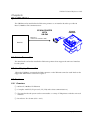
Introduction
The UB-E02 is the 10Base-T/100Base-TX Ethernet interface board designed for the EPSON® TM
printers. The board lets you connect your EPSON printer directly to your network and use it as a
kitchen printer.
Operating Environments
Supported Operating Systems
❏ Microsoft® Windows® 95, Windows® 98 Second Edition, Windows® 2000 Professional,
and Windows®XP Professional
❏ Windows NT® 4.0
Supported Protocols
❏ TCP/IP
Environments for Setup Utility
❏ EPSON TMNet WinConfig applies to the following versions of Windows:
•
Windows 95
•
Windows 98 Second Edition
•
Windows 2000 Professional
•
Windows XP Professional
•
Windows NT 4.0
❏ EPSON TMNet WebConfig is recommended to be used with the following internet browser:
•
Rev. A
Microsoft Internet Explorer version 5.0 or later
vii
Supported TM Printers
The following printers can use the UB-E02.
(The TM-J8000, TM-T285, and RP-U420 cannot use the UB-E02.
For new models, please ask your dealer.)
❏ TM-U200 Series
❏ TM-U210 Series
❏ TM-U230
❏ TM-U325
❏ TM-U590
❏ TM-U675
❏ TM-T88/T88II/T88III
❏ TM-T90
❏ TM-H5000/H5000II
❏ TM-H6000/H6000II
❏ TM-J2000/J2100
❏ TM-J7000/J7100
❏ TM-J7500/J7600
❏ TM-L90
viii
Rev. A
UB-E02 Technical Reference Guide
How to Use this Guide
Installation Overview
Be sure to read Chapter 1, “System Preparation,” before using the product.
Perform the following steps to install and configure the UB-E02. See the indicated chapters for
detailed information.
1. Install the UB-E02 in your printer. See Chapter 2.
2. Install the TCP/IP protocol in your operating system, if necessary. See Chapter 5.
3. Set the functions of the UB-E02. See Chapter 5.
4. To set the functions of the UB-E02 using the EPSON TMNet WebConfig utility, you need to
use Microsoft Internet Explorer. If it is not installed, install it, referring to the browser’s
manual.
Programming
The Chapter 6 provides you with a sample program of printing by network.
Appendix
The appendix provides you with the glossary.
Rev. A
ix
Contents
Chapter 1 System Preparation
Supported Operating Systems . . . . . . . . . . . . . . . . . . . . . . . . . . . . . . . . . . . . . . . . . . . 1-1
Supported Network Protocols . . . . . . . . . . . . . . . . . . . . . . . . . . . . . . . . . . . . . . . . . . . 1-1
Supported TM Printers . . . . . . . . . . . . . . . . . . . . . . . . . . . . . . . . . . . . . . . . . . . . . . . . . 1-1
Other Limitations . . . . . . . . . . . . . . . . . . . . . . . . . . . . . . . . . . . . . . . . . . . . . . . . . . . . . . 1-2
Chapter 2 Installation
Installation Precautions . . . . . . . . . . . . . . . . . . . . . . . . . . . . . . . . . . . . . . . . . . . . . . . . . 2-1
Unpacking . . . . . . . . . . . . . . . . . . . . . . . . . . . . . . . . . . . . . . . . . . . . . . . . . . . . . . . . . . . . 2-2
Part Names . . . . . . . . . . . . . . . . . . . . . . . . . . . . . . . . . . . . . . . . . . . . . . . . . . . . . . . . . . . 2-2
Functions . . . . . . . . . . . . . . . . . . . . . . . . . . . . . . . . . . . . . . . . . . . . . . . . . . . . . . . . . . . . . 2-2
Switch . . . . . . . . . . . . . . . . . . . . . . . . . . . . . . . . . . . . . . . . . . . . . . . . . . . . . . . . . . . . 2-2
LEDs . . . . . . . . . . . . . . . . . . . . . . . . . . . . . . . . . . . . . . . . . . . . . . . . . . . . . . . . . . . . . 2-2
UB-E02 Installation . . . . . . . . . . . . . . . . . . . . . . . . . . . . . . . . . . . . . . . . . . . . . . . . . . . . 2-3
Initializing UB-E02 . . . . . . . . . . . . . . . . . . . . . . . . . . . . . . . . . . . . . . . . . . . . . . . . . . . . . 2-6
UB-E02 Status Sheet Printing . . . . . . . . . . . . . . . . . . . . . . . . . . . . . . . . . . . . . . . . . . . . 2-6
FAQ . . . . . . . . . . . . . . . . . . . . . . . . . . . . . . . . . . . . . . . . . . . . . . . . . . . . . . . . . . . . . . . . . 2-7
Q1. The printer does not operate correctly.
("Serial interface" is printed by the self test for the printer.) . . . . . . . . . . . 2-7
Q2. The self test does not operate correctly. . . . . . . . . . . . . . . . . . . . . . . . . . . . . 2-7
Q3. Starting up the printer takes a long time. . . . . . . . . . . . . . . . . . . . . . . . . . . 2-7
Chapter 3 Utilities
Setting the IP Address . . . . . . . . . . . . . . . . . . . . . . . . . . . . . . . . . . . . . . . . . . . . . . . . . . 3-1
Setting the IP Address using EPSON TMNet WinConfig . . . . . . . . . . . . . . . . 3-1
Setting the IP Address Using the arp/ping Command . . . . . . . . . . . . . . . . . . 3-11
EPSON TMNet WinConfig Functions . . . . . . . . . . . . . . . . . . . . . . . . . . . . . . . . . . . . . 3-13
Menu Bar . . . . . . . . . . . . . . . . . . . . . . . . . . . . . . . . . . . . . . . . . . . . . . . . . . . . . . . . . 3-14
EPSON TMNet WebConfig Functions . . . . . . . . . . . . . . . . . . . . . . . . . . . . . . . . . . . . 3-20
Opening Screen . . . . . . . . . . . . . . . . . . . . . . . . . . . . . . . . . . . . . . . . . . . . . . . . . . . . 3-20
Protocol Information and Settings . . . . . . . . . . . . . . . . . . . . . . . . . . . . . . . . . . . . 3-22
Chapter 4 Programming Samples
Method of Printing to the UB-E02 . . . . . . . . . . . . . . . . . . . . . . . . . . . . . . . . . . . . . . . . 4-2
Buffer of the UB-E02 . . . . . . . . . . . . . . . . . . . . . . . . . . . . . . . . . . . . . . . . . . . . . . . 4-2
Direct Printing by PORT9100 . . . . . . . . . . . . . . . . . . . . . . . . . . . . . . . . . . . . . . . . . . . . 4-3
For Windows Console . . . . . . . . . . . . . . . . . . . . . . . . . . . . . . . . . . . . . . . . . . . . . . 4-3
For Linux . . . . . . . . . . . . . . . . . . . . . . . . . . . . . . . . . . . . . . . . . . . . . . . . . . . . . . . . . 4-5
Commands Sent to a TM Printer When the Power is On . . . . . . . . . . . . . . . . . . . . . 4-6
Monitoring of the ASB status . . . . . . . . . . . . . . . . . . . . . . . . . . . . . . . . . . . . . . . . . . . . 4-6
The Priorities of Printing . . . . . . . . . . . . . . . . . . . . . . . . . . . . . . . . . . . . . . . . . . . . . . . . 4-6
Time-out for Connection . . . . . . . . . . . . . . . . . . . . . . . . . . . . . . . . . . . . . . . . . . . . . . . . 4-6
Printer Operation by the UDP Commands . . . . . . . . . . . . . . . . . . . . . . . . . . . . . . . . 4-7
Commands Packets . . . . . . . . . . . . . . . . . . . . . . . . . . . . . . . . . . . . . . . . . . . . . . . . 4-7
03-0000 Retrieving Basic Information . . . . . . . . . . . . . . . . . . . . . . . . . . . . . . . . . 4-8
03-0010 Retrieving Status . . . . . . . . . . . . . . . . . . . . . . . . . . . . . . . . . . . . . . . . . . . 4-8
03-0011 Forced Transmission . . . . . . . . . . . . . . . . . . . . . . . . . . . . . . . . . . . . . . . . 4-9
03-0012 Reset . . . . . . . . . . . . . . . . . . . . . . . . . . . . . . . . . . . . . . . . . . . . . . . . . . . . . . 4-9
03-0013 Buffer Flash . . . . . . . . . . . . . . . . . . . . . . . . . . . . . . . . . . . . . . . . . . . . . . . . 4-10
03-0016 Clearing Connection Time-Out Timer . . . . . . . . . . . . . . . . . . . . . . . . . 4-10
Programming Sample . . . . . . . . . . . . . . . . . . . . . . . . . . . . . . . . . . . . . . . . . . . . . . 4-11
x Contents
Rev. A
UB-E02 Technical Reference Guide
Chapter 5 Specifications
Printer Connection . . . . . . . . . . . . . . . . . . . . . . . . . . . . . . . . . . . . . . . . . . . . . . . . . . . .
Line Display Connection . . . . . . . . . . . . . . . . . . . . . . . . . . . . . . . . . . . . . . . . . . . . . . .
Features . . . . . . . . . . . . . . . . . . . . . . . . . . . . . . . . . . . . . . . . . . . . . . . . . . . . . . . . . . . . . .
Overview . . . . . . . . . . . . . . . . . . . . . . . . . . . . . . . . . . . . . . . . . . . . . . . . . . . . . . . . .
Printing Functions . . . . . . . . . . . . . . . . . . . . . . . . . . . . . . . . . . . . . . . . . . . . . . . . .
Functions to Monitor Settings . . . . . . . . . . . . . . . . . . . . . . . . . . . . . . . . . . . . . . .
Maintenance Functions . . . . . . . . . . . . . . . . . . . . . . . . . . . . . . . . . . . . . . . . . . . . .
Hardware Specifications . . . . . . . . . . . . . . . . . . . . . . . . . . . . . . . . . . . . . . . . . . . . . . . .
Physical communications standard . . . . . . . . . . . . . . . . . . . . . . . . . . . . . . . . . .
Board size . . . . . . . . . . . . . . . . . . . . . . . . . . . . . . . . . . . . . . . . . . . . . . . . . . . . . . . .
External appearance and connector locations . . . . . . . . . . . . . . . . . . . . . . . . . .
Software Specifications . . . . . . . . . . . . . . . . . . . . . . . . . . . . . . . . . . . . . . . . . . . . . . . . .
Basic Communications Protocols . . . . . . . . . . . . . . . . . . . . . . . . . . . . . . . . . . . .
Printing Communications Protocols . . . . . . . . . . . . . . . . . . . . . . . . . . . . . . . . . .
Status Inquiry and Setting Protocols . . . . . . . . . . . . . . . . . . . . . . . . . . . . . . . . .
Automatic IP Address Assignment Protocols . . . . . . . . . . . . . . . . . . . . . . . . . .
Internal Settings . . . . . . . . . . . . . . . . . . . . . . . . . . . . . . . . . . . . . . . . . . . . . . . . . . .
Initializing . . . . . . . . . . . . . . . . . . . . . . . . . . . . . . . . . . . . . . . . . . . . . . . . . . . . . . . .
Version Upgrading . . . . . . . . . . . . . . . . . . . . . . . . . . . . . . . . . . . . . . . . . . . . . . . .
Environmental Specifications . . . . . . . . . . . . . . . . . . . . . . . . . . . . . . . . . . . . . . . . . . .
Storage Conditions . . . . . . . . . . . . . . . . . . . . . . . . . . . . . . . . . . . . . . . . . . . . . . . . . . . .
EMC and Safety Standards Applied . . . . . . . . . . . . . . . . . . . . . . . . . . . . . . . . . . . . . .
5-1
5-1
5-1
5-1
5-2
5-2
5-2
5-2
5-2
5-2
5-3
5-3
5-3
5-3
5-4
5-5
5-7
5-9
5-9
5-10
5-10
5-10
Appendix A Definitions
A . . . . . . . . . . . . . . . . . . . . . . . . . . . . . . . . . . . . . . . . . . . . . . . . . . . . . . . . . . A-1
D . . . . . . . . . . . . . . . . . . . . . . . . . . . . . . . . . . . . . . . . . . . . . . . . . . . . . . . . . . A-1
E . . . . . . . . . . . . . . . . . . . . . . . . . . . . . . . . . . . . . . . . . . . . . . . . . . . . . . . . . . A-1
I . . . . . . . . . . . . . . . . . . . . . . . . . . . . . . . . . . . . . . . . . . . . . . . . . . . . . . . . . . . A-1
M . . . . . . . . . . . . . . . . . . . . . . . . . . . . . . . . . . . . . . . . . . . . . . . . . . . . . . . . . . A-1
N . . . . . . . . . . . . . . . . . . . . . . . . . . . . . . . . . . . . . . . . . . . . . . . . . . . . . . . . . . A-1
P . . . . . . . . . . . . . . . . . . . . . . . . . . . . . . . . . . . . . . . . . . . . . . . . . . . . . . . . . . A-1
S . . . . . . . . . . . . . . . . . . . . . . . . . . . . . . . . . . . . . . . . . . . . . . . . . . . . . . . . . . A-1
T . . . . . . . . . . . . . . . . . . . . . . . . . . . . . . . . . . . . . . . . . . . . . . . . . . . . . . . . . . . A-1
U . . . . . . . . . . . . . . . . . . . . . . . . . . . . . . . . . . . . . . . . . . . . . . . . . . . . . . . . . . A-2
Rev. A
Contents xi
xii Contents
Rev. A
UB-E02 Technical Reference Guide
Chapter 1
System Preparation
1.1 Supported Operating Systems
❏ Microsoft Windows 95, Windows 98 Second Edition, Windows 2000 Professional,
and Windows XP Professional
❏ Windows NT 4.0
1.2 Supported Network Protocols
❏ LPR
❏ Socket printing (port 9100 for OPOS)
1.3 Supported TM Printers
The following printers can use the UB-E02.
❏ TM-U200 Series
❏ TM-U210 Series
❏ TM-U230
❏ TM-U325
❏ TM-U590
❏ TM-U675
❏ TM-T88/T88II/T88III
❏ TM-T90
❏ TM-H5000/H5000II
❏ TM-H6000/H6000II
❏ TM-J2000/J2100
❏ TM-J7000/J7100
❏ TM-J7500/J7600
❏ TM-L90
Rev. A
System Preparation 1-1
The following printers cannot use the UB-E02.
❏ TM-J8000, TM-T285, RP-U420
1.4 Other Limitations
Be sure to note the following:
❏ When the UB-E02 is installed, the display module connector (DM-D) of the TM printer
cannot be used.
CAUTION:
Do not connect the Ethernet connector cable to the display module connector (DM-D)
or the drawer kick-out connector.
1-2 System Preparation
Rev. A
UB-E02 Technical Reference Guide
Chapter 2
Installation
2.1 Installation Precautions
WARNING
❏ Before installing, disconnect the Power Unit from the TM Printer (as well as turning the
power switch off).
Even when the power switch is off, voltage is still present at some points on the circuit
board. Changing components while the Power Unit is connected can cause
damage to the UB-E02 and the printer.
❏ A grounded wrist strap should be worn during installation, to avoid damage from
static electricity.
❏ To avoid damage from static electricity when the unit is removed, place it on an
static-safe surface such as conductive foam.
❏ Protect the unit from vibration and shock that could damage to the unit.
❏ Be careful to avoid dropping conductive objects such as paper clips on the circuit
board, as they could short circuit connections and cause damage from excessive
current.
❏ This product should only be connected to the devices specified in this guide.
Connecting other devices could cause damage, fire or explosion.
❏ Do not attempt to wire this product other than as described in this document.
Improper wiring could cause damage, fire or explosion.
❏ Never disassemble or modify this product. Tampering with this product may result in
injury, fire, or electric shock.
❏ Do not use in locations subject to high temperature, humidity or dust levels.
Excessive temperature, humidity or dust may cause equipment damage, fire, or
shock.
❏ Never connect a public telephone line to the modular connector on this product.
❏ Parts on the circuit board may become hot during operation. Therefore, wait
approximately 10 minutes after turning the power off before touching them.
❏ To prevent the possibility of electrical shock, do not perform installation or connect
cables during a thunderstorm.
Rev. A
Installation 2-1
2.2 Unpacking
❏ UB-E02
❏ UB-E02 User’s Manual
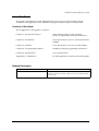
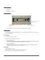
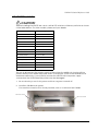
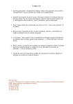
2.3 Part Names
Power supply connector
of the printer
10BASE-T/100BASE-TX LED (green) LED (yellow)
Ethernet interface
connector
Switch
Drawer kick-out
connector of the printer
Note: This photograph shows the TM-T88III printer with the UB-E02 installed.
2.4 Functions
The switch and LEDs of the UB-E02 provide you with important information on operation and
status of the UB-E02.
2.4.1 Switch
Type: Non-locking push switch
You can do the following with the switch.
❏ Setting initialization
All the parameters of internal settings for the UB-E02 can be set to the factory default values.
See “Initializing UB-E02” on page 6 of this chapter for more details.
❏ Status sheet printing
The internal setting parameters of the UB-E02 can be printed. See “UB-E02 Status Sheet
Printing” on page 6 of this chapter for more details.
2.4.2 LEDs
The UB-E02 has two LEDs.
The green LED is on when the Ethernet link is established.
The yellow LED is on when the printer receiving data.
2-2 Installation
Rev. A
UB-E02 Technical Reference Guide
2.5 UB-E02 Installation
CAUTION:
Before installing the UB-E02, be sure to set the DIP switches or Memory switches as shown
in the table below. For other models, please ask your dealer.
Model
Setting
TM-U200 Series
DIP SW 2-8: ON
TM-U210 Series
DIP SW 2-8: ON
TM-U230 Series
DIP SW 2-8: ON
TM-U325 Series
DIP SW 2-8: ON
TM-U590 Series
DIP SW 2-8: ON
TM-U675 Series
DIP SW 2-8: ON
TM-T88/T88II/T88III
DIP SW 2-8: ON
TM-T90
MSW 1-8: ON
TM-H5000/H5000II
DIP SW 2-8: ON
TM-H6000/H6000II
DIP SW 2-8: ON
TM-J7000/J7100
MSW 1-8: ON
TM-J7500/J7600
MSW 1-8: ON
TM-J2000/J2100
MSW 1-8: ON
TM-L90
MSW 1-8: ON
Be sure to disconnect the power supply of the printer (in addition to turning off the
power switch) .Even when the power switch is turned off, some of the internal circuit
board has electricity. If you install or remove the UB-E02 with the power supply
connected, the UB-E02 and the printer may be damaged.
1. Be sure that the power for the printer and host computer is turned off.
2. Install the UB-E02 in the printer.
If an interface circuit board is already installed, remove it and install the UB-E02.
remove screw
remove screw
Rev. A
Installation 2-3
3. Tighten the screws.
If you have removed an interface circuit board that was already installed, fix the UB-E02
using the removed screws.
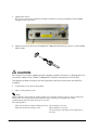
4. Plug the twist pair cable into the 10BASE-T/100BASE-TX Ethernet connector of the UB-E02
until it clicks.
CAUTION:
Be sure not to connect a telephone line, display module connector, or drawer kick-out
connector cable to the 10BASE-T/100BASE-TX Ethernet connector of the UB-E02.
The display module connector on the TM printer cannot be used when the UB-E02 is
installed.
5. Connect the power unit to the printer.
6. Turn on the printer power.
Note:
When initializing the UB-E02 by turning off the power and then turning it back on or by resetting the
printer, there is a waiting time until the network starts operating. During this time, all the
communicating functions of the network do not work.
The waiting time is:
When the IP address setting is Manual (Fixed): approximately 6 seconds
When the IP address setting is Auto:
approximately 13 seconds
(It can be longer, depending on the reply time of
the host.)
2-4 Installation
Rev. A
UB-E02 Technical Reference Guide
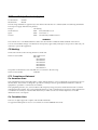
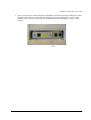
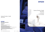
7. Print a status sheet to check whether the UB-E02 is installed correctly by holding the switch
down for more than 3 seconds when the printer is ready for printing. The version of the
UB-E02 and its settings are printed. See “UB-E02 Status Sheet Printing” on page 6 of this
chapter.
Switch
Rev. A
Installation 2-5
2.6 Initializing UB-E02
All the parameters of internal settings for the UB-E02 can be set to the factory default values.
Follow the steps below:
1. Turn off the printer power. Be sure to confirm that the LED lights are off.
2. Turn on the printer power while pressing the switch of the UB-E02 and hold the switch until
the factory default values are printed.
3. After "Resetting to Factory Default!" is printed, release the switch.
4. Initialization takes approximately 30 seconds. Do not turn off the printer power during the
initialization.
5. When the initialization is finished, the status sheet is printed. The following are printed on
the status sheet.
•
TCP/IP settings
•
SNMP settings
•
MAC address and version of UB-E02
•
Other status items of UB-E02
CAUTION:
Do not turn off the printer power until the status sheet is printed out.
2.7 UB-E02 Status Sheet Printing
The internal setting parameters of the UB-E02 can be printed. Follow the steps below:
1. Confirm that the printer power is on and the printer is ready for printing.
2. Press the switch of the UB-E02 and hold the switch more than 3 seconds.
3. After the status sheet printing starts, release the switch.
2-6 Installation
Rev. A
UB-E02 Technical Reference Guide
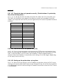
2.8 FAQ
2.8.1 Q1. The printer does not operate correctly. ("Serial interface" is printed by
the self test for the printer.)
2.8.1.1 A1. For TM-T90, TM-L90, TM-J2000, TM-J2100, TM-J7000, TM-J7100, TM-J7500, and
TM-J7600, set the #25 pin reset signal of the Memory switch set to disabled. For other
models, use the printer with the #31 pin reset signal of the DIP switch for parallel interface
enabled.
Model
Setting
TM-U200 Series
DIP SW 2-8: ON
TM-U210 Series
DIP SW 2-8: ON
TM-U230 Series
DIP SW 2-8: ON
TM-U325 Series
DIP SW 2-8: ON
TM-U590 Series
DIP SW 2-8: ON
TM-U675 Series
DIP SW 2-8: ON
TM-T88/T88II/T88III
DIP SW 2-8: ON
TM-T90
MSW 1-8: ON
TM-H5000/H5000II
DIP SW 2-8: ON
TM-H6000/H6000II
DIP SW 2-8: ON
TM-J7000/J7100
MSW 1-8: ON
TM-J7500/J7600
MSW 1-8: ON
TM-J2000/J2100
MSW 1-8: ON
TM-L90
MSW 1-8: ON
2.8.2 Q2. The self test does not operate correctly.
2.8.2.1 A2. Turn on the printer power while pressing the FEED button and hold the Feed
button until printing starts to perform the self test for the printer with the UB-E02. Printing
starts in approximately 6 seconds when the IP address is fixed or approximately 13
seconds when the IP address is acquired by auto setting. (It can be longer, depending
on the reply time of the host.)
2.8.3 Q3. Starting up the printer takes a long time.
2.8.3.1 A3. When the auto setting is set for IP address acquisition without a DHCP server,
starting up the printer takes about one minute. During this time, the self test for the printer
is not performed. Set the manual setting for IP address acquisition where the DHCP server
is not available.
Rev. A
Installation 2-7
2-8 Installation
Rev. A
UB-E02 Technical Reference Guide
Chapter 3
Utilities
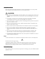
3.1 Setting the IP Address
To use the UB-E02 with TCP/IP, you first need to set its IP address. You can set the IP address
by using the EPSON TMNet WinConfig or arp/ping command.
arp/ping command
UB-E02
Refer to page 3-11
Setting IP address
EPSON TMNet
WinConfig
Web
Config
Win
Config
Refer to
page 3-20
Refer to
page 3-13
setting
Refer to Page 3-1
UB-E02
Setting functions
Set up for printing, referring to the OPOS/APD manual.
3.1.1 Setting the IP Address using EPSON TMNet WinConfig
Follow the steps below.
1. Set the TCP/IP of your operating system.
2. Install the EPSON TMNet WinConfig.
3. Set the IP address using EPSON TMNet WinConfig.
3.1.1.1 Setting the TCP/IP protocol in Your Operating System
To set the IP address, you need to install the TCP/IP protocol in your operating system. How to
set the TCP/IP protocol is explained for Windows 95, Windows 2000, and Windows NT 4.0.
Rev. A
Utilities 3-1
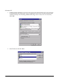
Windows 95
1. Double-click the Network icon in the Control Panel; then check whether TCP/IP is in the list
of installed network components on the Configuration menu. If it is already installed, click
Cancel and skip to the Installing TMNet WinConfig section. If TCP/IP is not in the list,
click Add.
2. Select Protocol and click Add.
3-2 Utilities
Rev. A
UB-E02 Technical Reference Guide
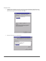
3. Select Microsoft from the list of manufacturers and TCP/IP from the Network protocols list.
Then click OK.
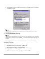
4. Double-click TCP/IP on the Configuration menu to open the TCP/IP Properties dialog box.
Make necessary settings, such as the IP address and subnet mask. Ask your network
administrator for the settings such as the IP address.
Note:
After the TCP/IP is installed, restart your computer and move on to the Installing EPSON TMNet
WinConfig section.
Rev. A
Utilities 3-3
Windows NT 4.0
1. Double-click the Network icon in the Control Panel to check whether the TCP/IP Protocol is
installed. If it is already installed, click Cancel and skip to the Installing TMNet WinConfig
section. If the component is not installed, click Add.
.
2. Select the TCP/IP protocol and click OK.
3-4 Utilities
Rev. A
UB-E02 Technical Reference Guide
3. If you continue installing the TCP/IP protocol, the TCP/IP Configuration dialog box
appears, and you can set the IP address. Ask your network administrator for your IP
address.
Note:
To check the IP address which has already been assigned, click the Protocols tab in the Network dialog
box, select TCP/IP Protocol, and then click the Properties button.
4. When the installation is complete, check items such as the IP address to make sure they have
been entered correctly.
Note:
After the TCP/IP is installed, restart your computer and move on to the Installing EPSON TMNet
WinConfig section.
Windows 2000
1. Double-click the Network and Dial Set Up icon in the Control Panel; then click Local Area
Connection Status.
Rev. A
Utilities 3-5
2. Click Properties and check whether the Internet Protocol (TCP/IP) check box is checked. If
not, click the check box.
Note:
After the TCP/IP is installed, restart your computer and move on to the Installing EPSON TMNet
WinConfig section.
3.1.1.2 Installing EPSON TMNet WinConfig
Note:
After the EPSON TMNet WinConfig is installed, if you add or remove protocols or services, the EPSON
TMNet WinConfig might not work correctly. In this case, uninstall the EPSON TMNet WinConfig and
reinstall it.
Please contact the dealer where you purchased the product to ask for the EPSON TMNet
WinConfig utility.
Installation Environments
Your computer should meet the following conditions:
❏ The hard disk must have unused memory of 3 MB or more.
❏ The operating system must be one of the following:
Windows 95, Windows 98 Second Edition, Windows 2000 Professional,
Windows XP Professional, Windows NT 4.0.
❏ IBM PC/AT compatible with the operating systems mentioned above.
3-6 Utilities
Rev. A
UB-E02 Technical Reference Guide
Installation with Windows 95
1. Unzip the file and start Setup.exe.
2. Install the EPSON TMNet WinConfig, following the instructions shown on your display.
3. When the installation is finished, click a check box, if necessary and then click Finish.
Rev. A
Utilities 3-7
3.1.1.3 Setting with the EPSON TMNet WinConfig
CAUTION:
Because the same IP address is set for all UB-E02 units in the factory, do not connect
more than one UB-E02 whose IP address is not changed from the factory setting. When
you set the IP address, connect the UB-E02 to the network and set the IP address one by
one.
Be sure not to turn off the printer or send printing data to the printer while setting. Do not
use the same IP address as that of other network devices or PCs.
Windows 95
1. Make sure Windows is running, the UB-E02 is connected to the network, and the printer is
turned on.
2. Click Start, point to Programs, point to EPSON TMNet WinConfig; then click EPSON
TMNet WinConfig.
3. Click the printer where you want to set the IP address, and then click the Configuration
button. (You might wait for 10 seconds or more to view the UB-E02 over the network on
your screen.)
Note:
If you have connected more than one printer to the network and do not know for which printer you want to
set the IP address, you can check the printer by finding out the MAC address of the UB-E02. The MAC
address can be fond on the status sheet or a label on the UB-E02. For printing the status sheet, see
“UB-E02 Status Sheet Printing” in Chapter 2.
3-8 Utilities
Rev. A
UB-E02 Technical Reference Guide
CAUTION:
When you cannot check the MAC address on the label on the UB-E02 that is installed on
the printer, be sure to finish the TM Net WinConfig by clicking Close from the Device tab;
then turn off the printer and remove the UB-E02 to check it.
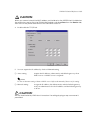
4. Double-click the TCP/IP tab.
5. You can acquire the IP address by Auto or Manual setting.
❏ Auto setting:
Acquire the IP address, subnet mask, and default gate way from
DHCP server. A DHCP server is required.
Note:
Do not use the auto setting without a DHCP server. Refer to the manual of the server for setting.
❏ Manual setting:
Assign the IP address, the Subnet mask, and the Default gateway.
Ask your administrator for the IP address and the Default gateway
to be set.
CAUTION:
Be sure that the Set by PING box is turned on if a setting by ping or arp command is
permitted.
Rev. A
Utilities 3-9
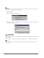
Note:
To confirm the current setting, print out the status sheet. Press down the switch more than 3 seconds in
the printable state; then the status sheet is printed out.
6. Click the OK button.
7. Click the OK button again to be sure.
8. Enter the password set in the print server; then click OK. If the password is not set, just click
OK without entering the password.
CAUTION:
After clicking OK, you must not turn off the printer while the new settings are being sent
to the UB-E02.
9. The update is complete when the message “Configuration is successfully done” appears.
Note:
To get the information for the UB-E02 for the other segments, refer to the EPSON TMNet WinConfig
Functions section.
3-10 Utilities
Rev. A
UB-E02 Technical Reference Guide
3.1.2 Setting the IP Address Using the arp/ping Command
You can set the IP Address using the arp/ping command. This way of setting is available with
the host, which is in the same segment as that of the UB-E02.
CAUTION:
When setting the IP address of the UB-E02, do not use the same IP addresses as that of
other network devices or PCs.
Here is an example of setting the IP address to 192.168.100.201.
❏ You will set the gateway address to the computer in which you will input the arp/ping
command.
❏ If a server or router acts as a gateway, type the gateway address.
❏ If there is no gateway, type the IP address of your computer.
❏ If you do not know the gateway address, ask your network administrator for it.
Note:
The IP address cannot be set without setting the gateway address.
1. Connect the printer with the UB-E02 installed to the network and turn on the printer.
2. Execute the commands as described in the following steps.
Note:
Be sure to execute the commands within 2 minutes. After 2 minutes, you must restart the commands from
the beginning.
3. Make the connection between the IP address which you want to set and the MAC address of
the UB-E02 by executing an arp command.
•
From the command line, type: arp-s [IP address] [MAC address]
Example using DOS: arp-s 192.168.100.201 00-00-48-83-00-00
Example using UNIX: arp-s 192.168.100.201 00:00:48:83:00:00
CAUTION:
When the UB-E02 is installed on the printer and the MAC address on the label on the
UB-E02 cannot be seen for sure, turn off the printer and then remove the UB-E02 to
confirm it.
Note:
The MAC address can be found on the status sheet or a label on the UB-E02. For printing the status sheet,
refer to the Initializing UB-E02 and Status Sheet Printing section in Chapter 2.
Rev. A
Utilities 3-11
4. Set the IP address to the UB-E02 using the ping command.
•
Example: ping 192.168.100.201
5. If the ping command is successful, the message “Reply From 192.168.100.201:
Bytes=32Time<10ms TTL=255” is shown. (The time indication will vary.)
6. Check if the IP address shown is 192.168.100.201.
Now, setting the IP address is complete. Next, set the default gateway and Subnet mask for the
UB-E02, referring to the EPSON TMNet WebConfig Functions.
3-12 Utilities
Rev. A
UB-E02 Technical Reference Guide
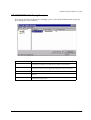
3.2 EPSON TMNet WinConfig Functions
This section describes the functions, including options of the EPSON TMNet WinConfig. The
main dialog box is shown below.
.
Item
Explanation
Tree view
The tree structure indicates the printer list. It consists of [All], which indicates
everything and [NEW], which indicates the printers newly added.
Item
You can change the order by clicking on an item. You can also adjust the
viewing size of the item by dragging a dividing line between the items.
List view
Indicates the information for the UB-E02.
Launch Browser
Select the IP address and then click this button. The EPSON WinConfig
appears.
Configuration
Select the IP address and then click this button. The setting window of the
EPSON WinConfig appears.
Rev. A
Utilities 3-13
3.2.1 Menu Bar
The table shows each item and its function.
Menu
Sub Menus
Explanation
Device
Setting
Start the setting of the UB-E02 selected
Launch Browser
Start up the TMNet WebConfig
Close Applications
Close the TMNet WinConfig
Indication
Update
Find the printers and update the list to show the latest
information.
Tool
Time-out setting
Set the time-out for data transmission and reception
to 2 to 120 seconds.
Find option
Set the IP find option.
Find the topics
Indicate the TMNet WinConfig help.
Version information
Indicate version information and copyright
information.
Help
3.2.1.1 Tool Menu
Time-out setting
Use Time-out setting to set the time-out for data transmission and reception. This can be set
from 2 to 120 seconds. If the time-out exceeds the value set, a communication error occurs.
3-14 Utilities
Rev. A
UB-E02 Technical Reference Guide
Search Options
If you want to show and set a UB-E02 that is controlled by TCP/IP and is outside the local
network, input the specific address in the Search Options to find that UB-E02.
The settings and values stored are effective after executing Update in Indication menu or
restarting the EPSON TMNet WinConfig.
Item
Explanation
Enabling a specific
address search
Search for the UB-E02 which is outside the network.
IP address
Input an IP address to be searched (0 ∼255).
Input as follows based on the network classes:
Class A: {Input]. [255]. [255]. [255]
Class B: [Input]. [Input]. [255]. [255]
Class C: [Input]. [Input]. [Input]. [255]
IP address list
Show the IP addresses that have been registered.
Add
Add to the IP address list. Up to 20 addresses can be added. Do not add the local
addresses.
Delete
Delete the IP addresses that will not be used.
Rev. A
Utilities 3-15
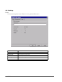
3.2.1.2 Settings
Printer
You can set the printer name. This also shows printer information.
Item
Explanation
Printer name
Set the printer name.
Model name
Shows the printer model name.
Printer ID
Shows the printer ID.
Printer type
Shows the printer type.
Version
Shows the ROM version.
3-16 Utilities
Rev. A
UB-E02 Technical Reference Guide
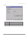
Print server
You can set administrator information. This also shows the printer server information
Item
Explanation
Administrator name
Shows the administrator name.
MAC address
Set the administrator name.
Hardware version
Shows the version of the UB-E02.
Software version
Shows the version of the UB-E02.
Rev. A
Utilities 3-17
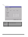
TCP/IP
You can set the TCP/IP.
Item
Explanation
Get IP address
Auto or Manual is selectable for the UB-E02.
Set by PING
Check the box if the setting of the UB-E02 by arg/ping is permitted.
Subnet mask
Set the subnet mask of the IP address.
Default gateway
Set the gateway.
IP address
Set the IP address for the UB-E02.
3-18 Utilities
Rev. A
UB-E02 Technical Reference Guide
Password
The EPSON TMNet WinConfig can set a password to protect the UB-E02 settings. The screen
shown below appears when you click OK or Return to Default.
❏ When you set the password the first time or you change the password, click the Change
button. No password is registered until you set one.
❏ When you click the Change button, the screen shown below appears. Input the password
(up to 20 single-byte alphanumeric characters) and then click OK. Capital and lower-case
characters are distinguished.
CAUTION:
The password is used for both the EPSON TMNet WinConfig and the EPSON TMNet Web
Config. When you use either utility, be sure to control the password.
The new password is effective after clicking the OK button to send the configuration
data. Right after the setting, using the Administrator password, input the current
password.
If you forget your password, you need to return all settings to the default settings. Refer
to the Initializing UB-E02 and Status Sheet Printing section in Chapter 2.
Rev. A
Utilities 3-19
3.3 EPSON TMNet WebConfig Functions
This section explains each function of the EPSON TMNet WebConfig.
Note:
Launch a browser and input the IP address of the UB-E02. Be sure not to launch the EPSON TMNet
WinConfig at the same time.
Address: http://(IP address of the UB-E02)/
Note:
Be sure to use Microsoft Internet Explorer 5.0 or later.
3.3.1 Opening Screen
3-20 Utilities
Rev. A
UB-E02 Technical Reference Guide
Item
Information
Configuration
Network
Configuration
Option
Rev. A
Explanation
General
Show the UB-E02 information.
TCP/IP
Show the TCP/IP information of the UB-E02.
SNMP
Show the SNMP information of the UB-E02.
TCP/IP
Set the TCP/IP of the UB-E02.
Community
Set the community.
IP Trap 1
Set the IP trap 1.
IP Trap 2
Set the IP trap 2.
Administrator
Set the banner on the opening screen.
Password
Set the password to protect the network settings.
Reset
Reset the UB-E02 or return to the factory default setting.
Advanced
Set communication method.
Utilities 3-21
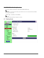
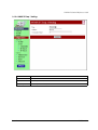
3.3.2 Protocol Information and Settings
3.3.2.1 General Information
Item
Interface card
Printer
3-22 Utilities
Explanation
Administrator
name
Shows the administrator name.
Location/Person
Shows the location or user name.
Model name
Shows the name of the interface card.
MAC address
Shows the MAC address of the UB-E02.
Software version
Shows the software version of the UB-E02.
Hardware version
Shows the hardware version of the UB-E02.
Printer ID
Shows the printer ID.
Printer status
Shows the printer status.
Rev. A
UB-E02 Technical Reference Guide
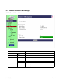
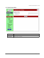
3.3.2.2 TCP/IP Information
Item
Explanation
Get IP Address
Shows the method of setting the IP address.
Set using Automatic
Private IP Addressing
(APIPA)
Shows the APIPA setting.
Set using PING
Shows the settings of prohibition and permission by the arp/ping command for the
UB-E02.
IP Address
Shows the IP address.
Subnet Mask
Shows the subnet mask of the IP address.
Default Gateway
Shows the default gateway.
Rev. A
Utilities 3-23
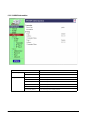
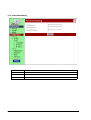
3.3.2.3 SNMP Information
Item
Community
IP Trap
3-24 Utilities
Explanation
Read Only
Shows he Read Community information.
Read/Write
Shows the Read/Write Community information.
Trap 1
Shows the Trap 1 information.
Address
Shows the Trap 1 Address.
Community Name
Shows the Trap 1 Community Name.
Trap 2
Shows the Trap 2 information.
Address
Shows the Trap 2 Address.
Community Name
Shows the trap 2 Community Name.
Rev. A
UB-E02 Technical Reference Guide
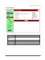
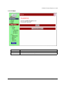
3.3.2.4 TCP/IP Setting
Item
Explanation
Get IP Address
Select the method of acquiring the IP address.
Set using Automatic
Private IP Addressing
(APIPA)
Set APIPA able/disable.
Set using PING
Select when the setting of the UB-E02 by arp/ping is permitted.
IP Address
Set the IP address of the UB-E02.
Subnet Mask
Set the subnet mask of the IP address.
Default Gateway
Set the default gateway.
Rev. A
Utilities 3-25
3.3.2.5 SNMP Communication Setting
Item
Explanation
Community
Read Only
The setting is fixed to “Public.”
Read/Write
Set the Read/Write Community Name (up to 16 characters).
3-26 Utilities
Rev. A
UB-E02 Technical Reference Guide
3.3.2.6 SNMP IP Trap 1 Setting
Item
Explanation
Trap
Set Trap 1.
Address
Set the Trap 1 Address.
Community Name
Set the Trap 1 Community Name.
Rev. A
Utilities 3-27
3.3.2.7 SNMP IP Trap 2 Setting
Item
Explanation
Trap
Set Trap 2.
Address
Set the Trap 2 Address.
Community Name
Set the Trap 2 Community Name.
3-28 Utilities
Rev. A
UB-E02 Technical Reference Guide
3.3.2.8 Administrator Setting
Item
Explanation
Administrator Name
Set the administrator name.
Location/Person
Set the location or user name.
Rev. A
Utilities 3-29
3.3.2.9 Password Setting
Item
Explanation
Old Password
Input the old password.
New Password
Input the new password.
Re-input Password
Re-input the new password.
3-30 Utilities
Rev. A
UB-E02 Technical Reference Guide
3.3.2.10 Reset
Item
Explanation
Reset
Resets the UB-E02 to its status when the power was turned on.
Factory Default
Returns to the factory default settings.
Rev. A
Utilities 3-31
3.3.2.11 Advanced
Item
Explanation
Physical Layer Setting
Set the communication method.
3-32 Utilities
Rev. A
UB-E02 Technical Reference Guide
Chapter 4
Programming Samples
This chapter describes the following:
❏ Method of printing to the UB-E02
❏ Direct printing by PORT9100
❏ Commands sent to a TM printer when the power is on
❏ Monitoring of the ASB status
❏ The rights of printing
❏ Time-out for connection
❏ Printer operation by UDP commands
Rev. A
•
Command packets
•
03-0000:retrieving the basic information
•
03-0010:retrieving the status
•
03-0011: forced transmission
•
03-0012: reset
•
03-0013: buffer flash
•
03-0016: clearing the connection time-out timer
•
Programming sample
4-1 Programming Samples
4.1 Method of Printing to the UB-E02
The UB-E02 has lpr protocol as its general print protocol. It is easy to print by using the lpr
protocol because the printing is also supported by the operating system.
However, the command statuses sent by the printer are ignored because the printing by lpr
applies only to the output of the printer.
The UB-E02 supports direct printing by TCP PORT9100. It is possible to control the printer
directly by an application with the ESC/POS commands through writing and reading to the
TCP PORT9100.
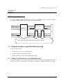
4.1.1 Buffer of the UB-E02
This is an image of the buffer. The buffer sent from the host computer to the TM printer is 16 KB.
The buffer sent from the TM printer to the host computer is 512 bytes.
4-2 Programming Samples
Rev. A
UB-E02 Technical Reference Guide
4.2 Direct Printing by PORT9100
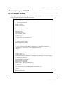
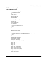
4.2.1 For Windows Console
The program is a sample of printing “EPSON UB-E02” to a TM printer with the UB-E02 from the
Windows shell, through the ethernet connection.
/* TCP9100 programming sample for win32
* HOW TO BUILD
* cl wtcp.cpp wsock32.lib
*/
#include <stdio.h>
#include <winsock.h>
int main(int argc, char* argv[])
{
WSADATA data;
SOCKET sock;
struct linger Linger;
struct sockaddr_in addr;
if (argc != 2) {
printf("usage: wtcp <IP address>\n");
exit(1);
}
/* Initialize windows socket */
WSAStartup(0x0101, &data);
/* Create socket */
if ((sock = socket(AF_INET, SOCK_STREAM, 0)) == INVALID_SOCKET) {
fprintf(stderr, "Error socket(): %d\n", WSAGetLastError());
exit(1);
}
/* Set connection timeout */
Linger.l_onoff = 1;
Linger.l_linger = 60;
setsockopt(sock, SOL_SOCKET, SO_LINGER, (char*)&Linger, sizeof(struct linger));
/* initialize the parameter */
memset(&addr, 0, sizeof(addr));
addr.sin_family = AF_INET;
addr.sin_port = htons(9100);
addr.sin_addr.s_addr = inet_addr(argv[1]);
/* connect */
if (connect(sock, (struct sockaddr*)&addr, sizeof(addr)) < 0) {
fprintf(stderr, "Error connect(): %d\n", WSAGetLastError());
exit(1);
}
printf("connected\n");
Rev. A
4-3 Programming Samples
/* send data */
send(sock, "EPSON\n", 6, 0);
/* gracefully close */
shutdown(sock, 1);/* SD_SEND */
while (1) {
char buf[64];
int n = recv(sock, buf, 64, 0);
if (n = SOCKET_ERROR || n == 0)
break;
}
shutdown(sock, 2);/* SD_BOTH */
/* close socket */
closesocket(sock);
return 0;
}
4-4 Programming Samples
Rev. A
UB-E02 Technical Reference Guide
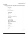
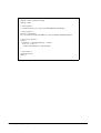
4.2.2 For Linux
The program is a sample of printing “EPSON UB-E02” to a TM printer with the UB-E02 from
Linux, through the ethernet connection.
/* TCP00 programming sample for LINUX
* HOW TO BUILD
* cc ltcp.c
*/
#include <stdio.h>
#include <netdb.h>
int main(int argc, char* argv[])
{
int sock;
struct sockaddr_in addr;
if (argc != 2) {
printf("usage: ltcp <ip address>\n");
exit(1);
}
/* create socket */
sock = socket(AF_INET, SOCK_STREAM, 0);
if (sock < 0) {
perror("socket()");
exit(1);
}
/* initialize the parameter */
memset(&addr, 0, sizeof(addr));
addr.sin_family = AF_INET;
addr.sin_port = htons(9100);
addr.sin_addr.s_addr = inet_addr(argv[1]);
/* connect */
if (connect(sock, (struct sockaddr*)&addr, sizeof(addr)) < 0) {
perror("connect()");
}
printf("connected\n");
/* send data */
send(sock, "EPSON\n", 6, 0);
/* close socket */
close(sock);
return 0;
}
Rev. A
4-5 Programming Samples
4.3 Commands Sent to a TM Printer When the Power is On
When the power is turned on, the UB-E02 transmits the following commands to the TM printer
and maintains the statuses. The UB-E02 acquires printer information by GS I and monitors the
printer status through the TMNet WebConfig using the GS a 255 command.
ESC/POC command descriptions:
•
GS I 1: printer ID
•
GS I 2: printer type ID
•
GS I 3: printer ROM version ID
•
GS a FFh: Enables ASB status
Note:
When the power is turned off or the printer is off-line, the commands above are not transmitted.
4.4 Monitoring of the ASB status
The UB-E02 monitors the ASB statuses transmitted from TM printers to control the printer
statuses from host computers. The printer can know the statuses by remote using the TMNet
WinConfig or the TMNet WebConfig.
If the printing data includes commands that disable the ASB such as ESC @ and GS a 00h, the
ASB status from the TM printer will not be transmitted afterward when the printer status is
changed and the UB-E02 cannot monitor the status of the TM printer.
To monitor the printer status, when there is a command that disables the ASB in a data string
sent by an application to the TM printer, transmit a command that enables the ASB.
4.5 The Priorities of Printing
The UB-E02 permits up to 3 requests of connecting regardless of the lpr/port9100 protocol.
Printing by the TM printer is given the first priority. Data transmission is blocked for other
requests until the first connection is closed (explicit close or close by time-out).
4.6 Time-out for Connection
If there is no data transmitted from the host for 5 minutes, regardless of the protocol, lpr/
port9100, the UB-E02 closes the connection. To continue the connection, the host needs to send
the UDP command explicitly.
4-6 Programming Samples
Rev. A
UB-E02 Technical Reference Guide
4.7 Printer Operation by the UDP Commands
By using the UDP commands, the following information can be received in order to recover
from abnormal operations and errors.
Function Code
Packet
Function
03-0000
Q
Acquires basic information
03-0010
Q
Acquires status
03-0011
C
Off-line forced transmission
03-0012
C
Reset
03-0013
C
Buffer flash
03-0016
C
Clears connection time-out timer
4.7.1 Commands Packets
Off-set
Size
Packet Transmission
Packet Reply
0
5
Character string “EPSON”
Character string “EPSON”
5
1
Packet type:
’Q’: Query
’C’: Command
Packet type reply:
’q’: Query reply
’c’: Command reply
6
1
Device type (0 × 03 fixed)
Device type (0 × 03 fixed)
7
1
Device number (0 × 00 fixed)
Device number (0 × 00 fixed)
8
2
Function number
Function number
10
2
0 × 00, 0 × 00 fixed
Result code
12
2
Length (n)
Length (n)
14
n
Command parameter
Reply data
The following values are replied for the packet reply result codes. Check the results in an
application.
❏ 0000h: Normal end
❏ FFFEh: No device requested
❏ FFFFh: Function requested are not supported
Rev. A
4-7 Programming Samples
4.7.2 03-0000 Retrieving Basic Information
4.7.2.1 Reply data
Off-set
Size
Description
14
1
Interface type
15
1
Communication method with TM printer
16
1
Printer ID acquired during a power-on
17
1
Printer type ID acquired during a power-on
18
1
Printer ROM version acquired during a power-on
19
n
Printer name character string (128 bytes)
4.7.3 03-0010 Retrieving Status
4.7.3.1 Reply data
Off-set
Size
Description
14
1
Reserved
15
4
ASB
19
4
ASB for Ink
23
4
ASB for optional functions
4-8 Programming Samples
Rev. A
UB-E02 Technical Reference Guide
4.7.4 03-0011 Forced Transmission
Transmission is done, regardless of the flow control between the TM printer and the UB-E02.
4.7.4.1 Set-up data
Off-set
Size
Description
14
1
Flow control
0: With flow control
1: No flow control (forced transmission)
15
2
Data length (n: maximum: 255)
17
n
Data length (maximum: 255)
4.7.4.2 Reply data
Off-set
Size
Description
14
1
Result
0: Normal
Except for 0: Failure
15
2
Data length
17
n
Data string
4.7.5 03-0012 Reset
4.7.5.1 Set-up data
Off-set
Size
Description
14
1
Reserved (undefined)
4.7.5.2 Reply data
Off-set
Size
Description
14
1
Result
0: Normal
Except for 0: Failure
❏ To reset the printer, the reset function should be enabled by a DIP switch of the printer.
❏ The UB-E02 is also reset when the printer is reset.
❏ After resetting, wait for approximately 10 seconds before accessing to the UB-E02, which is
the same as when turning on the power.
Rev. A
4-9 Programming Samples
4.7.6 03-0013 Buffer Flash
4.7.6.1 Reply data
Off-set
Size
Description
14
1
Result
0: Normal
Except for 0: Failure
❏ This clears only the buffer of the UB-E02 and cannot clear the receive buffer of the printer.
4.7.7 03-0016 Clearing Connection Time-Out Timer
Regularly send commands clearing the connection time-out timer to avoid time-out when data
is not sent for a certain period of time.
4.7.7.1 Set-up data
None
4.7.7.2 Reply data
Off-set
Size
Description
14
1
Result
0: Normal
Except for 0: Failure
4-10 Programming Samples
Rev. A
UB-E02 Technical Reference Guide
4.7.8 Programming Sample
4.7.8.1 For Windows Console
/* UDP3289 programming sample for win32
* HOW TO BUILD
* cc wudp.cpp wsock32.lib
*/
#include <stdio.h>
#include <winsock.h>
#define MAXBUF 512
char buf[MAXBUF];
int main(int argc, char* argv[])
{
WSADATA data;
SOCKET sock;
struct sockaddr_in addr;
int i, len, fromlen;
if (argc != 2) {
printf("usage: wudp <IP address>\n");
exit(1);
}
/* initialize windows socket */
WSAStartup(0x0101, &data);
/* Create socket */
if ((sock = socket(AF_INET, SOCK_DGRAM, 0)) == INVALID_SOCKET) {
fprintf(stderr, "Error socket(): %d\n", WSAGetLastError());
exit(1);
}
/* initialize the parameter */
memset(&addr, 0, sizeof(addr));
addr.sin_family = AF_INET;
addr.sin_port = htons(3289);
addr.sin_addr.s_addr = inet_addr(argv[1]);
/* make a packet (PRINTER STATUS) */
buf[0] = 'E';
buf[1] = 'P';
buf[2] = 'S';
buf[3] = 'O';
buf[4] = 'N';
buf[5] = 'Q'; // PacketType(Q)
buf[6] = 0x03; // DeviceType(3)
buf[7] = 0x00; // DeviceNumber(0)
buf[8] = 0x00; // Function(0010h)
buf[9] = 0x10;
buf[10] = 0x00; // Result
Rev. A
4-11 Programming Samples
buf[11] = 0x00;
buf[12] = 0x00; // Parameter length
buf[13] = 0x00;
/* send a packet */
i = sendto(sock, buf, 14, 0, (struct sockaddr*)&addr, sizeof(addr));
/* receive packet */
fromlen = sizeof(addr);
len = recvfrom(sock, buf, MAXBUF, 0, (struct sockaddr*)&addr, &fromlen);
/* print receive packet */
if (len) {
if ((buf[10] == 0x00) && (buf[11] == 0x00))
for (i = 0; i < len; i++)
printf("%3d:%02Xh\n", i, buf[i] & 0xff);
}
/* close socket */
closesocket(sock);
return 0;
}
4-12 Programming Samples
Rev. A
UB-E02 Technical Reference Guide
4.7.8.2 For Linux
/* UDP3289 programming sample for LINUX
* HOW TO BUILD
* cc ludp.c
*/
#include <stdio.h>
#include <netdb.h>
#define MAXBUF 512
char buf[MAXBUF];
int main(int argc, char* argv[])
{
int sock;
struct sockaddr_in addr;
int i, len;
socklen_t fromlen;
if (argc != 2) {
printf("usage: udp3289 IP_ADDRESS\n");
exit(1);
}
/* create sockets */
sock = socket(AF_INET, SOCK_DGRAM, 0);
if (sock < 0) {
perror("socket()");
exit(1);
}
/* initialize the parameter */
memset(&addr, 0, sizeof(addr));
addr.sin_family = AF_INET;
addr.sin_port = htons(3289);
addr.sin_addr.s_addr = inet_addr(argv[1]);
/* make a packet (PRINTER STATUS) */
buf[0] = 'E';
buf[1] = 'P';
buf[2] = 'S';
buf[3] = 'O';
buf[4] = 'N';
buf[5] = 'Q'; // PacketType (Q)
buf[6] = 0x03; // DeviceType(3)
buf[7] = 0x00; // DeviceNumber(0)
buf[8] = 0x00; // Function(0010h)
buf[9] = 0x10;
buf[10] = 0x00; // Result
buf[11] = 0x00;
buf[12] = 0x00; // parameter length Length
Rev. A
4-13 Programming Samples
buf[13] = 0x00;
/* send packet */
i = sendto(sock, buf, 14, 0, (struct sockaddr*)&addr, sizeof(addr));
/* receive packet */
fromlen = sizeof(addr);
len = recvfrom(sock, buf, MAXBUF, 0, (struct sockaddr*)&addr, &fromlen);
/* print receive packet */
if (len) {
if ((buf[10] == 0x00) && (buf[11] == 0x00))
for (i = 0; i < len; i++)
printf("%3d:%02Xh\n", i, buf[i] & 0xff);
}
/* close socket */
close(sock);
return 0;
}
4-14 Programming Samples
Rev. A
UB-E02 Technical Reference Guide
Chapter 5
Specifications
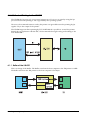
The UB-E02 can be installed in the TM-series printers as an interface board to provide 10
Base-T/100 Base-TX communications.
EPSON PRINTER
WITH
UB-E02
EPSON
PRINTER
Ethernet
(10Base-T/100Base-TX)
Host PC
5.1 Printer Connection
The interface board can be installed in TM-series printers that support the universal interface
board system.
5.2 Line Display Connection
When the UB-E02 is connected, the DM connector on the TM unit cannot be used. Refer to the
Supported TM Printers section in Chapter 1.
5.3 Features
5.3.1 Overview
❏ 10 Base-T/100 Base TX Ethernet
❏ Complies with TCP/IP protocol (LP, LPR, and socket communications)
❏ The interface board system can be connected to a variety of TM printers with the universal
interface
❏ Board size: 70 × 58 mm {2.76 × 2.28"}
Rev. A
Specifications 5-1
5.3.2 Printing Functions
❏ Printing by standard protocols (printing of network objects through a device driver
❏ Socket printing by unique socket communications (port 9100 for OPOS)
❏ Supports OPOS/Unimini/JavaPOS
5.3.3 Functions to Monitor Settings
❏ Various settings and states displayed by Web browser
❏ IP address setting by arp + ping
❏ Supports DHCP
❏ Supports APIPA
❏ ping response
❏ Status printing function
❏ Module setting initialization using the Test switch
❏ Status monitoring by ENPC
❏ Status monitoring by SNMP
5.3.4 Maintenance Functions
❏ Firmware writing through the network
5.4 Hardware Specifications
5.4.1 Physical communications standard
10 Base-T/100 Base-TX (IEEE 802.3)
5.4.2 Board size
70 × 58 mm {2.76 × 2.28"}
5-2 Specifications
Rev. A
UB-E02 Technical Reference Guide
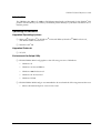
5.4.3 External appearance and connector locations
10BASE-T Ethernet
interface connector LED (green)
LED (red)
Switch
5.5 Software Specifications
5.5.1 Basic Communications Protocols
Protocol
Application
IP, ARP, ICMP, UDP, TCP
Basic communications protocols for various functions (used by the following
higher-level protocols)
5.5.2 Printing Communications Protocols
Protocol
Application
LP, LPR
Transfer printing data
TCP Socket Port
Transfers printing data and printer status by direct socket communications
(bidirectional)
5.5.2.1 LP, LPR
❏
Remote printer name:
aux
❏ Maximum simultaneous connections: 3
❏
Number of connections that can print: 1 (other users wait until done)
❏
Time out:
5 minutes
❏
Job deletion:
not supported
❏
Banner printing:
not supported
5.5.2.2 Socket Communications
❏
Port type:
TCP comm. port for direct printing
❏ Port number:
9100
❏
Port communication direction:
bidirectional
❏
Time out:
5 minutes
Rev. A
Specifications 5-3
5.5.3 Status Inquiry and Setting Protocols
Protocol
Application
HTTP
Display module status and make settings by Web browser.
SNMP
Acquire and set module settings or printer status by custom or general purpose MIB tool.
ENPC
Acquire and set module settings or printer status by custom setup utility.
5.5.3.1 HTTP
❏ Port number:
80
❏
User name:
EPSON
❏
Password:
None
❏
Maximum simultaneous connections: 1
❏
HTTP version:
HTTP/1.1
5.5.3.2 SNMP (MIB)
Terminology:
MIB: Management Information Base
PDU: Protocol Data Unit
❏
SNMP version:
❏ Transport protocol:
SNMP v1 (RFC1157) compliant
SNMP v2 not supported
UDP/IP
❏ CommunityEach item may be up to 16 ASCII characters
Community
Object Attribute
Default
#1
Read-only
"Public"
#2
Read-write
None
Trap #1
Read-write
None
Trap #2
Read-write
None
❏ Trap destination
Up to two settable IP addresses
❏ MIB support
Part of MIB-II (RFC1213)
Part of Host Resource MIB
Part of Print Server MIB
Part of Printer MIB
5-4 Specifications
Rev. A
UB-E02 Technical Reference Guide
❏ PDU support
Get Request
Get Next Request
Set Request
Get Response
Trap
❏ Server port number
161
❏ Trap sending port number
162
5.5.3.3 ENPC
❏ Protocol:
UDP/IP
❏ UDP port number:
3289
❏ Compatible packet types:
Probe
Initialize
Query
Setup
Notify
5.5.4 Automatic IP Address Assignment Protocols
The UB-E02 supports the DHCP and APIPA protocols for automatic IP address assignment. The
automatic assignment is performed according to the following sequence, and if a protocol is
disabled or fails, the next protocol is tried. When an IP address is acquired, the next protocol is
not tried.
Protocol
Sequence
Application
DHCP
1
Acquires IP address
APIPA
2
Assigns IP address
manual setting
3
Uses the internal set parameters
5.5.4.1 IP Address Acquisition by DHCP
❏ Items to acquire:
IP address, subnet mask, gateway address
❏
DHCP Discover retries:
4 times
❏
DHCP Discover retry interval:
1st: 4 seconds
3rd: 15 seconds
❏
DHCP Request retries:
10 times
❏
DHCP Request retry interval:
15 seconds
Rev. A
2nd: 7 seconds
4th: 32 seconds
Specifications 5-5
5.5.4.2 IP Address Assignment by APIPA
❏ Item to acquire:
IP Address
❏ Range of address:
169.254.1.0 to 169.254.254.255
Any IP address in the above range that is not used in the same network is assigned. However,
communication over the router is not possible when the IP address is set by APIPA.
5.5.4.3 Manual Setting
The UB-E02 operates in accordance with the IP address stored in the internal parameter settings.
5-6 Specifications
Rev. A
UB-E02 Technical Reference Guide
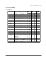
5.5.5 Internal Settings
5.5.5.1 Item List
Exclusive
utility
HTTP
Initial value
Ref
Setting
Ref
Setting
Ref
IP address
192.168.192.168
o
o
o
o
o
Subnet mask
255.255.255.0
o
o
o
o
o
Gateway address
0.0.0.0
o
o
o
o
o
Item
Parameter
Status
printout
DHCP function
Disable/Enable
Disable
o
o
o
o
o
APIPA function
Disable/Enable
Disable
o
o
o
o
o
arp/ping IP setting
Disable/Enable
Enable
o
o
o
o
×
Community name 1
(read-only)
Max. 16 chars.
“public”
o
×
o
×
o
Community name 2
(read-write)
Max. 16 chars.
None
o
o
o
o
o
IP Trap 1
Disable/Enable
Disable
o
o
o
o
×
IP Trap 2
Disable/Enable
Disable
o
o
o
o
×
Community name
(IP Trap #1)
Max. 16 chars.
None
o
o
o
o
×
Community name
(IP Trap #2)
Max. 16 chars.
None
o
o
o
o
×
IP Trap #1 Address
None
o
o
o
o
×
IP Trap #2 Address
None
o
o
o
o
×
Password
None
×
o
×
o
×
Auto negotiation
o
o
o
o
o
Hardware version
o
×
o
×
o
Firmware version
o
×
o
×
o
MAC address
o
×
o
×
o
Communication
mode setting
Auto Negotiation
/10BASE-T Half
/10BASE-T Full
/100BASE-TX Half
/100BASE-TX Full
o = possible × = impossible
Rev. A
Specifications 5-7
5.5.5.2 Internal Parameter Setting Methods
1. Using the exclusive utility.
2. Using a browser
3. Using arp and ping commands (only to set IP address)
5.5.5.3 Setting with Exclusive utility
Settings cannot be made by the specified application software when the ENPC protocol is used.
A dedicated utility which can set miscellaneous with the ENPC protocol is provided by EPSON.
5.5.5.4 Setting with Browser
Setting can be made by an HTTP browser when connected to the module. The new IP address
takes effect when the printer power is turned off and back on.
5.5.5.5 Setting the IP Address with arp + ping
This function is available when it has been enabled.
The setting can be made from a host in the same segment as the module.
The host must support both arp and ping commands.
The new IP address takes effect when the module responds to the ping command.
Example-1: using SunOS
arp -s 123.456.789.123 00:00:48:06:00:01 temp
ping 123.456.789.123
Example-2: using Windows
arp -s 123.456.789.123 00-00-48-06-00-01
ping 123.456.789.123
5.5.5.6 How to check the Mac Address
The Mac address of the UB-E02 can be checked with any of the following methods:
❏ Printing the status sheet
❏ Checking the label on the UB-E02
❏ Checking the HTTP browser
❏ Checking the printer self-test (however, the self-test function is limited for each model.)
5-8 Specifications
Rev. A
UB-E02 Technical Reference Guide
5.5.6 Initializing
To initialize the UB-E02 when the power is turned on or reset, the standby period is required for
10 seconds. During this period. All network functions do not work.
The waiting time is:
When the IP address setting is Manual (Fixed):
When the IP address setting is Auto:
approximately 6 seconds
approximately 13 seconds
(It can be longer, depending on the reply
time of the host.)
5.5.7 Version Upgrading
The module can upgrade its own firmware over the network.
5.5.7.1 Supported protocol
❏ TFTP
5.5.7.2 Upgrade Methods
❏ By TFTP command (for Windows XP/2000/NT4.0)
For more information, ask your dealer.
Rev. A
Specifications 5-9
5.6 Environmental Specifications
Temperature:0 to 50° C {32 to 122° F}
Humidity:10 to 90% RH (non-condensing)
5.7 Storage Conditions
Temperature:
-10 to 50° C {14 to 122° F}
❏ Humidity:10 to 90% RH (non-condensing)
5.8 EMC and Safety Standards Applied
Europe:
CE Marking
EN55022 Class B
EN50024
IEC61000-4-2
IEC61000-4-3
IEC61000-4-4
IEC61000-4-5
IEC61000-4-6
IEC61000-4-11
The printer in which the UB-E02 is installed does not conform to the following:
EN45501
North America: (EMI) FCC/ICES-003 Class A
Japan:
(EMC) VCCI Class A
Oceania:
(EMC) AS/NZS 3548, CISPR22 Class B
5-10 Specifications
Rev. A
UB-E02 Technical Reference Guide
Appendix A
Definitions
A
ASB— Auto Status Back: The feature that allows the printer to send the status information back
to the host computer automatically.
ARP —Address Resolution Protocol: Protocol which converts IP address to Ethernet address.
D
Domain—A group of computers administered together.
DHCP—Dynamic Host Configuration Protocol: Protocol which administers IP addresses, which
operates on the UDP, in the whole network system together.
E
Ethernet—LAN, using CSMA/CD method.
I
ICMP—Internet Control Message Protocol: a protocol which notifies an error status to a sender
when an error occurs.
M
MIB—Management Information Base: a set of variables (database) that a gateway running
SNMP maintains.
N
netmask—A binary value used for a sub-netwok and IP inter-networks.
P
ping—Command to test an IP connection.
S
SNMP—Simple Network Management Protocol: a standard protocol used to monitor IP
gateways, hosts, and the networks to which they are attached.
T
TCP—Transmission Control Protocol used for reliable end-to-end communication over an IP
connection.
Rev. A
Definitions A-1
TCP/IP—Name given to the suite of protocols (including but not limited to TCP and IP) that
govern the transmission and services of a network. The TCP indicates a transport layer and the
IP indicates an internet layer.
TCP port—A logical connection point in the software on a TCP/IP host.
U
UDP—User Datagram Protocol: a connectionless type of a protocol which is suitable for
transferring small packets.
A-2 Definitions
Rev. A
EPSON
SEIKO EPSON CORPORATION
Printed in Japan