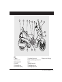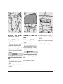
1
ATLANTIC 500
use+maintenancebook
aprilia part# 8104589
© 2002 aprilia s.p.a. - Noale (VE)
SAFETY INFORMATION
The following conventions are used to identify
safety information throughout the manual.
This symbol identifies safety-related
information.
Whenever you see this symbol in the
manual or attached to the vehicle,
use utmost care to avoid the risk of injury.
Disregarding the instructions identified by
this symbol may put your safety, as well
as that of other persons or of the vehicle at
risk!
TECHNICAL INFORMATION
Any operations preceded by this
symbol must be repeated on the
opposite side of the vehicle.
Unless expressly specified otherwise,
assembly is a reversal of the dismantling
procedure.
The terms “left” and “right” are referred to the
motorcycle when viewed from the riding
position.
First edition: November 2002
Reprint:
WARNING
Disregarding these indications may lead
to severe injury or death.
CAUTION
Produced and printed by:
DECA s.n.c.
Via Risorgimento, 23/1 - Lugo (RA) - Italia
Tel. +39 - 0545 35235
Fax +39 - 0545 32844
E-mail: [email protected]
www.decaweb.it
On behalf of:
aprilia s.p.a.
via G. Galilei, 1 - 30033 Noale (VE) - Italy
Tel. +39 - (0)41 58 29 111
Fax +39 - (0)41 44 10 54
www.aprilia.com
2
use and maintenance Atlantic 500
Disregarding these indications may lead
to minor injury or vehicle damage.
NOTE
The term “Note” in this manual
precedes important information or
instructions.
WARNINGS - PRECAUTIONS GENERAL ADVICE
Before starting the engine, carefully read
this manual paying special attention to
section “SAFE RIDING”.
Your safety and that of other road users
depends as much on your ability to respond
to other traffic and unexpected occurrences
as on your familiarity with your vehicle, the
vehicle’s efficiency and your knowledge of
basic “SAFE RIDING” techniques. Becoming
familiar with your vehicle is the key to deal
with traffic effectively and safely.
NOTE This manual forms an integral part
of the vehicle and must remain with the
vehicle, even if the vehicle is re-sold.
The information contained in this manual was
correct and up-to-date at the time of going to
print. However, minor discrepancies between
manual specifications and your vehicle are
possible as a result of aprilia’s ongoing
efforts to improve product design. Please
refer to your aprilia Official Dealer for any
doubts about the information contained in
this manual.
For inspections and repairs not expressly
described in this manual, to purchase of
aprilia genuine spare parts, accessories
and other products, or simply for technical
advice on specific matters, contact aprilia
Official Dealers and Service Centres only for
guaranteed prompt, quality service.
Owners who use their vehicles in these
countries must:
– Have affected components replaced with
those having country-specific approval
at an aprilia Official Dealer and
– Have the vehicle tested at the required
intervals.
Throughout the manual, the following symbols
are used to identify the different versions:
NOTE
VERSION:
After purchase, please report the
identification data indicated on the SPARE
PARTS IDENTIFICATION LABEL in the table
here below. The label is attached to the lefthand frame member. Remove the left
inspection cover to give access to the label,
see pag. 53 (REMOVING THE RIGHT AND
LEFT INSPECTION COVERS).
Thank you for choosing aprilia. Enjoy your
ride!
All rights to electronic storage, reproduction
and total or partial adaptation, with any
means, reserved in all Countries.
NOTE Emission and noise standards in
force in some countries require periodical
testing.
Identification data are:
– YEAR = year of manufacture (Y,1,2,...);
– I.M.= engineering change index (A,B,C,...);
– COUNTRY CODES = country for which
the vehicle is approved (I,UK,A,...).
You will be asked to provide this information
when purchasing spare parts or model-specific
accessories from aprilia Official Dealers.
Automatic light switching version
(Automatic Switch-on Device)
Option
Italy
Singapore
United Kingdom
Slovenia
Austria
Israel
Portugal
South Korea
Finland
Malaysia
Belgium
Chile
Germany
Croatia
France
Australia
Spain
Greece
United States of
America
Brazil
Holland
South Africa
Switzerland
New Zealand
Denmark
Canada
Japan
use and maintenance Atlantic 500
3
GENERAL INDEX
SAFETY INFORMATION .............................. 2
TECHNICAL INFORMATION ........................ 2
WARNINGS - PRECAUTIONS GENERAL ADVICE ........................................ 2
GENERAL INDEX ......................................... 4
SAFE RIDING ............................................... 5
BASIC SAFETY RULES ................................ 6
CLOTHING ................................................... 9
ACCESSORIES ........................................... 10
LOAD .......................................................... 10
ARRANGEMENT OF THE MAIN ELEMENTS ........ 12
ARRANGEMENT OF THE CONTROLS /
INSTRUMENTS - KEY ...................................... 14
INSTRUMENTS AND INDICATORS .......... 14
INSTRUMENTS AND INDICATORS TABLE ......... 15
KEY CONTROLS ........................................ 17
CONTROLS ON THE LEFT
SIDE OF THE HANDLEBAR ....................... 17
CONTROLS ON THE RIGHT SIDE OF THE
HANDLEBAR .............................................. 18
IGNITION SWITCH ..................................... 19
STEERING LOCK ....................................... 19
DIGITAL CLOCK/DATE LIQUID CRISTAL .......
DISPLAY ...................................................... 20
MULTIFUNCTION LIQUID CRISTAL
DISPLAY ...................................................... 21
DIGITAL ODOMETER ................................. 22
TOOL KIT .................................................... 23
UNLOCKING/LOCKING THE SADDLE ....... 23
GLOVE COMPARTMENT ........................... 23
SMALL STORAGE COMPARTMENT ......... 24
BAG HOOK ................................................. 24
HELMET HOOK .......................................... 24
MAIN COMPONENTS ....................................... 25
FUEL ........................................................... 25
LUBRICANTS ............................................. 26
BRAKE FLUID - Recommendations ............. 27
DISC BRAKES ............................................ 27
CHECKING BRAKE FLUID LEVEL ............. 28
COOLANT ................................................... 29
4
use and maintenance Atlantic 500
CHECKING AND TOPPING UP .................. 30
TYRES ........................................................ 31
MUFFLER/EXHAUST SILENCER .............. 32
INSTRUCTIONS FOR USE ............................... 33
PRE-RIDE CHECKS CHART ..................... 33
STARTING .................................................. 34
MOVING OFF - RIDING ............................. 36
RUNNING-IN .............................................. 38
STOPPING .................................................. 38
PLACING THE VEHICLE ON THE STAND ........ 39
SUGGESTIONS TO AVOID THEFT ............ 39
MAINTENANCE ................................................ 40
PERIODIC MAINTENANCE CHART .......... 41
IDENTIFICATION DATA .............................. 43
FRAME NUMBER ...................................... 43
ENGINE NUMBER ...................................... 43
CHECKING AND TOPPING UP ENGINE OIL
LEVEL .......................................................... 44
CHANGING ENGINE OIL
AND THE ENGINE OIL FILTER .................. 45
CHECKING AND TOPPING
UP TRANSMISSION OIL LEVEL ................. 45
CHANGING TRANSMISSION OIL .............. 46
AIR CLEANER ............................................ 47
CHECKING THE BRAKE PADS
FOR WEAR ................................................ 48
CHECKING THE STAND ............................ 50
CHECKING THE SWITCHES ..................... 50
CHECKING THE FRONT AND
REAR SUSPENSION .................................. 50
REAR SUSPENSION ADJUSTMENT ........ 51
CHECKING THE STEERING ...................... 51
CHECKING ENGINE PIVOT SHAFT .......... 52
REMOVING THE RIGHT AND LEFT
INSPECTION COVERS .............................. 53
REMOVING THE FRONT FAIRING ............ 53
REMOVING THE REARVIEW MIRRORS ......................................... 54
REMOVING THE FRONT COVER ............. 54
THROTTLE TWISTGRIP ADJUSTMENT ... 55
SPARK PLUG .............................................. 56
BATTERY
57
BA
TTER
Y....................................................
HYDROGEN GAS
BATTER
TTERY
LONG
INACTIVITY OF
THE BATTERY ............ 57
AND
ELECTROL
YTE
ELECTROLYTE
REMOVING THE BATTERY COVER ..........
CHECKING AND CLEANING THE BATTERY
LEAD CONNECTIONS AND TERMINALS .......
REMOVING THE BATTERY .......................
CHECKING BATTERY FLUID LEVEL .........
CHARGING THE BATTERY .......................
INSTALLING THE BATTERY .......................
REPLACING THE FUSES ...........................
ARRANGEMENT OF AUXILIARY
FUSES (FRONT COVER) ..........................
ARRANGEMENT OF MAIN FUSES
(BATTERY COMPARTMENT) ....................
VERTICAL ADJUSTMENT
OF THE HEADLIGHT BEAM .......................
HORIZONTAL ADJUSTMENT
OF THE HEADLIGHT BEAM .......................
BULBS .........................................................
REPLACING THE BULBS OF THE
FRONT DIRECTION INDICATORS ............
REPLACING THE HEADLIGHT BULBS ......
LOW BEAM BULBS .....................................
HIGH BEAM BULBS ....................................
PARKING LIGHT BULBS .............................
REPLACING THE TAIL LIGHT BULBS ........
REPLACING THE NUMBER PLATE BULB .
REPLACING THE HELMET
COMPARTMENT LIGHT BULB ..................
CHANGING THE THIRD STOP BULBS .....
TRANSPORT ....................................................
DRAINING THE FUEL TANK ......................
CLEANING ........................................................
LONG INACTIVITY ......................................
TECHNICAL DATA ...........................................
LUBRICANT CHART ..................................
WIRING DIAGRAM - Atlantic 500 ................
58
58
58
59
59
59
60
60
61
61
62
62
62
63
63
64
64
64
65
66
66
67
67
68
69
70
74
78
safe riding
BASIC SAFETY RULES
To ride a motorcycle, you must satisfy certain
legal requirements (driving licence, minimum
age, health conditions and fitness, insurance
cover, state taxes, vehicle registration,
number plate, etc.).
Practice riding in areas away from traffic or
on private ground until you become familiar
the vehicle and its controls.
6
use and maintenance Atlantic 500
Alcohol, drugs, psychotropic substances and
some medicines may affect your riding leading
to an accident.
Do not ride when you feel unwell, distracted,
tired or drowsy.
Most road accidents are caused by
inexperienced riders.
NEVER lend the vehicle to beginners or
anyone unless you are sure they meet the
requirements.
Observe all road signs as well as national
and local road regulations.
Avoid obstacles that could damage the
vehicle or make you lose control.
Avoid sudden manoeuvres that put your
safety and that of other persons at risk (for
example: rearing up on the back wheel,
speeding, etc.). Adjust your speed and riding
to road surface conditions, visibility, etc.
Avoid riding in the slipstream created by
preceding vehicles in order to increase your
speed.
Always keep both hands on the handlebars
and both feet on the footrest platform (or on
the footrests), in the correct posture.
Do not stand up or stretch your limbs while
riding.
use and maintenance Atlantic 500
7
OIL
Keep your eyes on the road and pay close
attention to other traffic. Do not smoke, eat,
drink or read while riding.
COOLER
Use only the recommended fuels and
lubricants specified in the “LUBRICANT
CHART”. Make it a rule to check oil, fuel and
coolant levels frequently.
If the vehicle has been involved in an
accident or has fallen over, check the control
levers, pipes, wires, braking systems and
critical parts for damage.
If necessary, have the vehicle inspected by
an aprilia Official Dealer. Special attention
should be paid to frame, handlebars,
suspension, safety parts and all the devices
that you are not able to inspect yourself.
Report any malfunction to help mechanics in
their work.
Never use the vehicle when the amount of
damage makes it unsafe to ride.
8
use and maintenance Atlantic 500
ONLY ORIGINALS
A12
345
Do not change the position, inclination or
colour of: number plate, direction indicators,
lights and horns.
Any such changes to the vehicle will
invalidate the guarantee.
Making changes to the vehicle and/or
removing original components can compromise vehicle performance and safety or make
it illegal to ride.
Observe all law regulations and national and
local regulations applicable to vehicle
equipment.
In particular, avoid any changes apt to
upgrade vehicle performance or alter its
original specifications.
Racing on public roads is prohibited by the
law.
Do not ride off the road.
CLOTHING
Always wear an approved safety helmet and
fasten it securely. The helmet must not be
damaged, must fit correctly and the visor
must be clean.
Wear protective clothing. To ensure you are
easily seen, choose bright colours. Clothing
with reflective strips is also very effective.
Protective clothing protects you in the event
of a fall and helps other road users to see
you, reducing the risk of an accident.
Wear close-fitting clothing, fastened at the
wrists and ankles.
Loose clothing or items, such as strings,
belts or neckties may impair your movements
while riding or become tangled in the wheels
or other moving parts.
use and maintenance Atlantic 500
9
Do not keep any pointed or sharp objects,
such as keys, pens, glass items, etc. in
your pockets. They might cause injury in the
event of a fall. Do not allow your passenger
to keep such objects.
10
use and maintenance Atlantic 500
ACCESSORIES
The owner of the vehicle is responsible for
the choice, installation and use of any
accessory.
Ensure that any accessory you install is
does not cover the horn or the lights or impair
their operation, be in the way of suspension
travel or steering angle, impair the operation
of the vehicle controls, reduce ground
clearance or lean-in angle.
Do not install accessories that hinder access
to the vehicle controls, lengthening your
response time in an emergency.
Large fairings and windshields affect vehicle
aerodynamics and stability, especially at high
speed.
After installing any accessory, make sure it
is firmly secured to the vehicle and does not
create a hazard when riding. Do not add any
electrical devices or modify those fitted to
your vehicle. Overloading might kill the engine
unexpectedly while riding or a power shortage
might render the horn and lights inoperative.
Use only genuine aprilia accessories.
LOAD
Be careful when loading your luggage. Place
your luggage as close as possible to the
centre of gravity of the vehicle and ensure
the load is distributed evenly to avoid
imbalance. Make sure the load is firmly
secured to the vehicle, especially during a
long trip.
KG!
Do not hang bulky, heavy and/or dangerous
objects on the handlebars, mudguards and
forks. This might slow down steering response
and adversely affect handling.
Do not secure bulky luggage to the sides of
the vehicle, which could hit persons or object
while riding and make you lose control of the
vehicle.
Do not carry luggage unless it is firmly
secured to the vehicle.
Luggage should not protrude exceedingly
over the luggage rack or cover the lights,
horn or indicators.
Do not exceed the maximum load allowed.
Excess load will make the vehicle unstable
and affect steering.
ARRANGEMENT OF THE MAIN
Do not carry animals or children on the glove
compartment or on the luggage rack.
use and maintenance Atlantic 500
11
ELEMENTS
3
4
2
7
5
6
1
13
KEY
1) Expansion tank
2) Coolant expansion tank plug
3) Rear brake fluid reservoir
4) Bag hook
5) Helmet hook
6) Air cleaner
12
use and maintenance Atlantic 500
12
11
10
9
7) Crash helmet compartment
8) Converter air cleaner cover
9) Centre stand
10) Passenger left footrest
11) Side stand
12) Spark plug
8
13) Left inspection cover
1
2
3
4
5
6
7
8
10
9
13
KEY
1) Battery
2) Main fuse carrier
3) Passenger grab rail
4) Fuel tank
5) Fuel tank filler cap
6) Fuel tank filler cap flag
12
11
7) Front brake fluid reservoir
8) Ignition switch/steering lock/seat lock
9) Horn
10) Auxiliary fuse carrier
11) Right inspection cover
12) Passenger right footrest
13) Engine oil level / filler plug
ANORDNUNG
DER
use and maintenance Atlantic 500
13
INSTRUMENTS AND INDICATORS
ARRANGEMENT OF THE CONTROLS/INSTRUMENTS
4
6
2
1
17
15 16
4
5
14
21
10
13
11
8
6
3
ABS
12
7
2
1
9
8
7
ARRANGEMENTOFTHECONTROLS/INSTRUMENTS–KEY
1) Electric controls on the left side of the handlebar
2) Front and rear brake lever (integral braking system)
3) Left rear-view mirror
4) Instruments and indicators
5) Right rear-view mirror
6) Front brake lever
7) Throttle twistgrip
8) Electric controls on the right side of the handlebar
- )
9) Ignition switch / steering lock ( ).
10) loudspeakers protective grid (
INSTRUMENTS AND INDICATORS – KEY
)
1) Red engine oil pressure light (
2) Green left turn indicator light ( )
3) Digital odometer
4) Speedometer
14
use and maintenance Atlantic 500
5
9
10
20
18
3
19
5) Green right turn indicator light ( )
)
6) Blue high beam light (
7) Amber low fuel light ( )
8) Fuel level indicator ( )
9) Digital clock function and setting buttons
10) Digital clock
11) Coolant temperature indicator ( )
12) Red coolant high temperature light ( )
13) Green low beam light (
)
)
14) Parking brake light (
)
15) Amber side stand down light (
16) “EFI” warning light
17) Rev counter
18) LCD display
19) 3 display function selection, and 18 and 3 resetting
) (for versions with ABS only)
20) Red ABS light (
)
21) Red anti-theft (IMMOBILIZER) light (
INSTRUMENTS AND INDICATORS TABLE
When the key is turned to ON “ ”, all warning lights, the dashboard lights and the segments of the
three displays come on for an instrumentation check-up and go out after three seconds.
CAUTION
Description
Function
Right indicator repeater light ( )
Blinks when the right direction indicator is on.
Left indicator repeater light ( )
Engine oil pressure light (
Blinks when the left direction indicator is on.
)
Comes on briefly each time the ignition switch is set to “
” with the engine stopped.
Doubles as LED test light.
The light must go out as soon as engine is fired.
If the light comes on during the normal engine operation, it
CAUTION
means that engine oil pressure in the circuit is too low. Stop
the engine immediately and contact an aprilia Official Dealer.
Digital odometer
Gives total distance covered in kilometres, TRIP1 and TRIP2 (see page 22).
Speedometer
High beam light (
Gives road speed
)
Comes on when the high beam is on or when you flash the high beam (PASSING).
Low fuel light ( )
Comes on when there are about 4 litres of fuel left in the tank.
Fuel level indicator ( )
Indicates approximate fuel level in the tank.
When the pointer reaches the red area, it means that the quantity of fuel
left in the tank is about 4 litres.
Refuel as soon as possible, see page 25 (FUEL).
Digital clock
Anti-theft device (immobilizer) light (
Parking brake light
Hour and date display, see page 20 (DIGITAL CLOCK/DATE DISPLAY).
)
Blinks when the engine is off as a deterrent to prevent theft.
Indicates that the anti-theft system is operating.
(where fitted). Indicates that the hand brake is pulled.
Release brake before start.
CAUTION
use and maintenance Atlantic 500
15
Description
Function
ABS (Anti-Lock Braking System) (
)
(where fitted). Anti-lock braking system check-up. Comes on in the event of a malfunction.
If the light comes on during normal engine operation, it means
CAUTION
that there is a failure in the anti-locking system.
Stop the engine immediately and contact an aprilia Official Dealer.
High Coolant temperature indicator ( )
Indicates the approximate temperature of coolant in the engine. When the pointer begins to
move away from the “Min” level, the engine is warm enough to rride. The central portion of the
scale corresponds to normal running temperature range. If the pointer reaches the red area or
the warning light comes on, stop the engine and check coolant level, see page 29 (COOLANT).
Exceeding the maximum temperature allowed (red “Max” area
CAUTION
of the scale) may lead to severe engine damage.
Coolant high temperature light ( )
It comes on when the coolant temperature pointer reaches the red area. Immediately stop the
engine and check coolant level, see page 29 (COOLANT).
Exceeding the max. temperature allowed for a long period
CAUTION
may lead to severe engine damage.
Low beam light (
Comes on when the low beam is on.
Side stand light (
)
)
Comes on when the side stand is down.
When the side stand is down, the warning light comes on and
CAUTION
engine starting is inhibited.
Electronic fuel injection control light (EFI)
Comes on, for about three seconds, whenever the ignition switch is set to “ ” with the engine
stopped, thus testing the injection system operation. The light must go out as soon as engine is fired.
If the light comes one during the normal engine operation, it
CAUTION
means that the fuel electronic injection system is not working
properly. Stop the engine immediately and contact an aprilia Official Dealer.
Rev counter
Indicates the number of engine revolutions.
LCD multifunction display
External temperature, max. speed, average speed, battery voltage, average fuel consumption
after the last “RESET”, chronometer and kilometers till next scheduled service are displayed.
See page 21 (LCD MULTIFUNCTION DISPLAY).
16
use and maintenance Atlantic 500
KEY CONTROLS
CONTROLS ON THE LEFT SIDE OF THE HANDLEBAR
NOTE The electric components work only when the ignition switch
is in position “
3
2
5
”.
1) HORN BUTTON ( )
Press it to operate the horn.
PASSING
2) DIRECTION INDICATOR SWITCH (
)
Move the switch to the left in order to signal your intention to turn
left; move the switch to the right to signal a right turn. Press the
switch at the centre in to cancel the signal.
The indicators are self-cancelling and turn off automatically after
40 seconds or after the vehicle has covered 500 m. The selfcancelling feature only operates when the vehicle is in motion.
3) DIMMER SWITCH ( - ) / HIGH BEAM FLASHER (PASSING )
Set the dimmer switch to “ ”, to turn on the low beam, set it to
) to turn on the high beam.
Push the dimmer switch to position “PASSING
beam.
” to flash the high
NOTE Release the switch to stop the flasher.
4) MODE BUTTON (MODE)
Press it repeatedly to select the various indications provided by
the multifunction display.
MODE
1
4
)
5) HAZARD BUTTON (
OPERATION Press the button to activate the emergency stop
blinker. When the blinker is on, it is possible to turn the ignition
switch to ( ) and extract the key.
DEACTIVATION
Insert the key into the ignition switch and turn it to position “
press the HAZARD button again to turn off the blinker.
use and maintenance Atlantic 500
”,
17
CAUTION
Leaving the ignition switch in position “ ” when the engine is
stopped may flatten the battery.
After stopping the vehicle, stop the engine and then turn the
ignition switch to position “ ”.
1
2) STARTER BUTTON (
)
When pressed, the starter button “ “, turns the engine over. See
page 34 (STARTING) for starting procedure.
DEACTIVATION
When the key is inserted into the ignition switch and turned to “
the device is automatically disconnected.
2
CONTROLS ON THE RIGHT SIDE OF THE HANDLEBAR
NOTE The electric components work only when the ignition
switch is in position “ ”.
1) ENGINE KILL SWITCH (
-
)
WARNING
Do not operate the engine kill switch “
-
” while riding.
This is a safety or emergency switch. When it is in position “
the engine can be started. When set to position “
the engine.
18
use and maintenance Atlantic 500
”,
”, it will stop
”,
2
Position
ZADI
1
P
ZADI
PUSH
PU
IGNITION SWITCH
STEERING LOCK
The ignition switch (1) is positioned on the
right side, near the steering tube.
NOTE The key (2) operates the ignition
switch /steering lock, the saddle lock and
the glove compartment flap.
Two keys are delivered along with the vehicle
(one spare key).
NOTE
vehicle.
Do not keep the spare key on the
SH
WARNING
Never turn the key to position “ ” while
riding or you might lose control of the
vehicle.
OPERATION
To lock the steering:
◆ Turn the handlebar fully to the left.
◆ Turn the key (2) to position “ ”.
◆ Extract the key.
Function
The steering
is locked.
It is not
possible to
Steering lock start
the
engine or
switch on
the lights
Key removal
It is
possible to
remove the
key
Neither the
engine nor
the lights
can be
operated.
It is possible
to remove
the key.
The engine
and
the
lights can be
operated.
It is not
possible to
remove the
key.
To open the compartments:
Push in the key (2) and turn it clockwise to
open the small storage compartment.
◆ Push in the key (2) and turn it anticlockwise
to release/lock the saddle and access the
compartment under the saddle.
◆
use and maintenance Atlantic 500
19
1
Setting the clock:
Setting the date:
NOTE The clock must be set with the engine
stopped, the vehicle at standstill and the
direction indicators off.
◆
◆
ABS
2
◆
3
◆
DIGITAL CLOCK/DATE LIQUID CRISTAL
DISPLAY
NOTE The Displays only operate when the
ignition switch is set to “ ”.
Display functions (1):
◆ Normal display: hours and minutes.
◆ Date display: press the key SET (3), the
month and the day are displayed for less
than five seconds.
20
use and maintenance Atlantic 500
◆
◆
◆
Press the key W (2) for more than three
seconds to enter the clock setting mode
(only when the time is displayed).
Press or hold down the key SET (3) until
setting the correct time.
Press the key W (2) to confirm the time
setting. The clock switches to minutes
setting automatically.
Press or hold down the key SET (3) until
setting the minutes.
Press the key W (2) to confirm the minutes
setting.
The clock setting procedure is finished
and the clock returns to normal operation.
◆
◆
◆
◆
◆
Press the key W (2) for more than three
seconds to enter the date setting mode
(only when the date is displayed).
Press or hold down the key SET (3) until
setting the day.
Press the key W (2) to confirm the day
setting. The display switches automatically
to month setting.
Press or hold down the key SET (3) until
setting the month.
Press the key W (2) to confirm the month
setting.
The date setting procedure is finished and
the date display returns to normal
operation.
WARNING
Clock and date display may only be set
when the engine is stopped, the vehicle is
at standstill and the direction indicators
are off.
Press the MODE button repeatedly to select
in the order:
6
2
7
8
9
10
5
ZADI
mph
PU
SH
AVG V BATT Km/h Km/l
External temperature in ° C
MODE
Vmax
SERVICE
°C
°F
LAP
CEV
11
Maximum speed (Vmax) + kph or mph
MODE
12
Average speed AVG (kph or mph)
MODE
4
3
1
MULTIFUNCTION LIQUID CRYSTAL
DISPLAY
When the ignition key (1) is set to “ “, all
segments of the multifunction display come
on (this is a test of all components). The
display resumes the last function set after
the vehicle was stopped.
CAUTION
After the first 1000 kilometres and every
6000 kilometres afterwards, a SERVICE
warning is displayed.
When you see this message, contact an
aprilia Official Dealer to have the vehicle
serviced as specified in the periodic
maintenance chart, see page 41 (PERIODIC
MAINTENANCE CHART).
13
The different functions are selected and
displayed by pressing the MODE button (2)
placed on left side of the handlebar.
The segments of the multifunction display
are:
Lap timer indicator (3), service term icon (4),
average mph speed icon (5), average speed
(6), battery charge icon (7), average kph
speed icon (8) (the same icon is used for
“consumption” indication expressed in Km/
l), consumption expressed in mi/Gal. (used
on versions (
) only) (9), maximum
speed icon (10), icon of the external temperature expressed in Celsius degrees (° C)
(11), icon of the external temperature
expressed in Fahrenheit degrees (° F) (12),
six-digit reading of the set functions identified
by the corresponding icons (13).
Battery charge (Vbatt)
MODE
Fuel consumption (km/l or mi/Gal.)
MODE
Lap timer (LAP)
MODE
Kilometres till next service (SERVICE)
MODE
use and maintenance Atlantic 500
21
Press the TRIP key repeatedly to access in
the order:
ZADI
3
PU
Odometer (ODO)
SH
TRIP
4
7
1
6
5
Trip meter 2
TRIP
DIGITAL ODOMETER
NOTE These indications may only be reset
NOTE The displays only operate when the
when the odometer is displayed on the right
digital display.
◆ Press the TRIP key (1) for more than
three seconds.
ignition switch is set to “
NOTE The displayed function will be reset.
LAP TIMER START/STOP AND RESET
NOTE These indications may only be reset
when the odometer is displayed on the right
digital display.
START/STOP:
Press the MODE key for more than three
seconds.
RESET:
◆ Press the TRIP key (1) for more than
three seconds only when the lap timer is
stopped.
use and maintenance Atlantic 500
TRIP
2
RESETTING AVERAGE AND MAXIMUM SPEED,
FUEL CONSUMPTION AND LAPTIMER
22
Trip meter 1
ODO TRIP 1 TRIP 2
RESETTING TRIP 1 AND TRIP 2
“.
When the ignition key (3) is set to “ “ , all
segments of the display come on to test
components for proper operation. The initial
display shows the odometer.
The segments of the Display are:
Odometer display icon (4), TRIP 1 display
icon (5), TRIP 2 display icon (6), and fivedigit reading of selected indication (7).
◆
Press the TRIP key (1) for more than three
seconds when the TRIP meter you wish to
reset is displayed.
NOTE The function displayed currently will
be reset.
3
1
7
8
6
ZADI
4
PU
SH
2
5
aprilia
TOOL KIT
UNLOCKING/LOCKING THE SADDLE
The tool kit (1) is fixed inside the helmet
compartment under the saddle.
◆
To reach it:
Raise the saddle, see page 23 (UNLOCKING
/ LOCKING THE SADDLE).
The tool kit includes:
– 4 mm Allen wrench;
– Double head/flat-blade screwdriver;
– handgrip for screwdriver;
– 3 mm Allen wrench;
– 16x70 mm socket wrench with hexagon
ring;
– 13 mm combination wrench;
– spanner wrench with square snug;
– tool bag.
◆
◆
◆
Insert the key (2) into the saddle lock (3).
Press and turn the key (2) anticlockwise.
The pneumatic piston keeps the saddle
raised (4) and the light inside the saddle
compartment comes on.
To lock the saddle, lower it and then press
down (without exerting too much pressure)
until the lock becomes engaged.
WARNING
Make sure the saddle is locked securely
before riding.
GLOVE COMPARTMENT
The glove compartment can accommodate
bulky objects when you leave your bike
unattended.
◆ Insert the key (5) into the ignition switch (6).
◆ Press and turn the key clockwise.
◆ The compartment flap (7) will open.
◆ A 12V power socket (8) is fitted inside the
glove compartment.
◆ The power socket can be used to recharge
small appliances rated up to 180 W (mobile phone, inspection lamp, etc.).
CAUTION
Prolonged use of the power socket with the
engine stopped may flatten the battery.
use and maintenance Atlantic 500
23
3
1
2
SMALL STORAGE COMPARTMENT
◆
◆
◆
Push on the top section of the door (1).
The door clicks open to give access to the
compartment.
To close the door, push gently until hearing
an audible click.
BAG HOOK
HELMET HOOK
WARNING
Do not hang heavy or bulky bags on the
hook, or this might adversely affect
manoeuvrability and impair foot movement.
The bag hook (2) is mounted to the inner
shield at the front end.
Maximum load allowed: 1.5 kg
The helmet hook (3) is located under the
saddle, on vehicle left side: to gain access
to this part, raise the saddle as described in
“UNLOCKING/LOCKING THE SADDLE” (page 23).
◆ Hook helmet and lower saddle.
WARNING
Use helmet hook when the vehicle is not
running. Never leave helmets hooked when
riding the vehicle.
24
use and maintenance Atlantic 500
MAIN COMPONENTS
FUEL
WARNING
The fuel used to operate engines is highly
flammable and becomes explosive under
particular conditions. Refuelling and engine
service should take place in a wellventilated area with the engine stopped.
Do not smoke when refuelling or in the
proximity of sources of fuel vapours. Avoid
contact with open flames, sources of sparks
or any other source which may ignite the
fuel or lead to explosion. Take care not to
spill fuel out of the filler, or it may ignite
when in contact with hot engine parts. In
the event of accidental fuel spillage, make
sure the affected area is fully dry before
starting the engine. Fuel expands from heat
and when left under direct sunlight. Never
fill the fuel tank up to the rim. Tighten the
filler cap securely after each refuelling.
Avoid contact with skin. Do not inhale
vapours. Do not swallow fuel. Do not
transfer fuel between different containers
using a hose.
1
3
2
DO NOT RELEASE FUEL INTO THE
ENVIRONMENT.
KEEP AWAY FROM CHILDREN.
Use only premium-grade unleaded fuel with a
minimum octane rating of 91 (RON) and 81
(MON).
To reach the filler cap:
Insert the key (1) into the lock (2) of the
filler cap flap, which is positioned between
the footrest platforms.
◆ Turn the key clockwise and pull to open
the flap.
◆ Unscrew the filler cap (3).
◆
TANK CAPACITY (reserve included):
– 16.5 !
FUEL RESERVE :
– 4!
use and maintenance Atlantic 500
25
LUBRICANTS
ENGINE OIL
Check engine oil level every 3000 km (1875
miles), see page 44 (CHECKING AND
TOPPING UP OIL LEVEL).
WARNING
Prolonged or repeated contact with oil may
cause severe skin damage.
Wash your hands thoroughly after handling
oil.
NOTE
Use oil meeting 5/W 40
specifications, see page 74 (LUBRICANT
CHART).
Wear latex gloves during servicing.
CAUTION
KEEP AWAY FROM CHILDREN.
Do not overfill (top up beyond the “Max”
level).
DO NOT RELEASE INTOTHE ENVIRONMENT.
CAUTION
TRANSMISSION OIL
Handle carefully.
Do not spill oil!
Avoid smearing the components, the area
in which you are working and the
surrounding area.
Remove any trace of oil.
Check transmission oil level every 6000 km
(3750 miles).
In case of leakage or malfunctions, contact
an aprilia Official Dealer.
Have oil level checked and oil changed at an
aprilia Official Dealer.
26
use and maintenance Atlantic 500
Change transmission oil after the first 1000
km (625 miles) and then every 24.000 km
(15000 miles)
Have engine oil changed after the first 1000
kilometres (625 miles). Afterwards:
– Have engine oil changed every 6000 km
(3750 miles).
– Check oil level every 3000 km (1875 miles)
and top up as required.
Have engine oil changed at an aprilia Official
Dealer.
BRAKE FLUID - Recommendations
NOTE This vehicle is fitted with front and
rear disc brakes.
Each braking system is operated by an
independent hydraulic circuit. The information
provided below applies to both braking
systems.
WARNING
Ensure that the brake discs and brake
linings have not become contaminated with
oil or grease. This is particularly important
after servicing or inspections.
Make sure the brake lines are not twisted
or worn.
KEEP AWAY FROM CHILDREN.
WARNING
Any sudden changes in play or hardness in
the brake lever are warning signs of
problems with the hydraulic circuits.
If in doubt about the braking efficiency of
your bike or if you are not able to perform
routine checks, contact an aprilia Official
Dealer.
DO NOT RELEASE BRAKE FLUID INTO THE
ENVIRONMENT.
DISC BRAKES
WARNING
The brakes are critical to your safety and
must always be kept in sleek running order.
Check the brakes before each ride.
A dirty disc soils the pads, leading to loss
of braking. Dirty pads must be replaced,
whereas a dirty brake disk may be cleaned
with a high-quality degreasing product.
Have brake fluid changed at an aprilia
Official Dealer every two years.
use and maintenance Atlantic 500
27
CHECKING BRAKE FLUID LEVEL
Check level as follows:
-MIN-
NOTE
Place the vehicle on firm, level
WARNING
Do not ride when brake fluid level is below
the “MIN” mark.
ground.
◆
1
◆
◆
NOTE This vehicle is fitted with front and
rear disc brakes. Each braking system is
operated by an independent hydraulic circuit.
The information provided below applies to
both braking systems.
Brake fluid level decreases gradually as the
brake pads wear down.
The brake reservoirs are placed under the
handlebar cover, near the brake lever
connections.
Check brake fluid level in the reservoirs at
regular intervals - see (CHECKING BRAKE
FLUID LEVEL) at the side - and inspection
the brake pads periodically for wear, see
page 48 (CHECKING THE BRAKE PADS FOR
WEAR)
WARNING
Do not ride if the braking system is leaking.
28
use and maintenance Atlantic 500
Place the vehicle on the centre stand.
Turn the handlebar. The fluid in the reservoir
must be parallel with the “MIN” mark on
the sight glass (1).
Ensure that fluid level in the reservoir is
above the “MIN” mark on the sight glass (1).
MIN = minimum level.
WARNING
Brake fluid level decreases gradually as
the brake pads wear down.
Check the brake pads and brake disc for
wear, see page 48 (CHECKING THE BRAKE
PADS FOR WEAR).
If the brake pads and/or the brake disc are
in good condition:
◆ Contact an aprilia Official Dealer and have
brake fluid level topped up.
◆
WARNING
Check braking efficiency.
When the brake lever has exceeding travel
or if you notice a loss of braking, contact
an aprilia Official Dealer. The braking
system may need bleeding.
COOLANT
1
CAUTION
Do not ride when coolant is below the “MIN”
level.
Check coolant level every 2000 km (1250
miles) and after a long trip. Have coolant
changed at an aprilia Official Dealer every
two years.
WARNING
Coolant is toxic when ingested. Contact
with eyes or skin may cause irritation. In
the event of contact with eyes, rinse
repeatedly with abundant water and seek
medical advice. In the event of ingestion,
induce vomiting, rinse mouth and throat
with abundant water and seek medical
advice immediately.
DO NOT RELEASE INTO THE
ENVIRONMENT.
KEEP AWAY FROM CHILDREN.
Take care not to spill coolant onto hot engine
parts. It may ignite and produce invisible
flames. Wear latex gloves when servicing.
Have coolant changed at an aprilia Official
Dealer.
Coolant mixture is a solution of 50% water
and 50% anti-freeze.
This is the ideal solution for most operating
temperatures and provides good corrosion
protection.
This solution is also suited to the warm
season, as it is less prone to evaporative
loss and will reduce the need for top-ups. In
addition, less water evaporation means fewer
minerals salts depositing in the radiator, which
helps preserve the efficiency of the cooling
system.
When temperature drops below zero degrees
centigrade, check the cooling system
frequently and add more anti-freeze (up to
60% maximum) to the solution.
Use distilled water in the coolant mixture.
WARNING
Do not remove the expansion tank plug (1)
when the engine is hot, since coolant is
under pressure and very hot.
Contact with skin or clothes, may cause
severe scalding and/or damage.
use and maintenance Atlantic 500
29
1
2
3
MAX
MIN
CHECKING AND TOPPING UP
WARNING
Wait for the engine to cool down before
checking or topping up coolant level.
Stop the engine and wait until it has cooled
down.
NOTE Place the vehicle on firm and level
ground.
◆ Open the small storage compartment, see
page 23 (GLOVE COMPARTENT).
◆ Check that coolant level in the expansion
tank (1) is between the “MIN” and “MAX”
marks.
◆
MIN = minimum level.
MAX = maximum level.
30
use and maintenance Atlantic 500
If not so:
Remove the front cover, see page 54
(REMOVING THE FRONT COVER)
◆ Turn the filler cap (2) anticlockwise to
release it, but do not remove the cap.
◆ Allow a few seconds for any residual
pressure to discharge.
◆
NOTE A breather pipe (3) is connected to
filler cap (2). Do not force or disconnect the
breather pipe (3).
◆
Unscrew and remove the filler cap (2).
WARNING
Coolant is toxic when ingested. Contact
with eyes or skin may cause irritation.
Do not put your fingers or any other object
into the filler opening in order to ensure
that there is coolant.
CAUTION
Never top up beyond the “MAX” level mark
or coolant will leak out when the engine is
running.
◆ Top up with coolant, see page 74
(LUBRICANT CHART) up to about the
“MAX” mark.
◆ Refit the filler cap (2).
CAUTION
If coolant level drops too quickly or the
tank is empty, check the cooling circuit for
leaks. Have the leak repaired at an aprilia
Official Dealer.
◆
Refit the front cover, see page 54
(REMOVING THE FRONT COVER).
1
Some of the tyre types approved for this
vehicle are fitted with wear indicators.
There are various types of wear indicators.
Inspect tread surface and check for wear.
Badly worn tyres adversely affect traction
and handling.
Enquire about correct wear inspection procedure with your supplier.
Old tyres may not ensure full grip due to
material ageing – even when they are still
within the wear limit – and must be
replaced.
TYRES
This vehicle is fitted with tubeless tyres.
WARNING
Check tyre inflation pressures periodically
with the tyres at room temperature, see
page 70 (TECHNICAL DATA).
Checking pressure on hot tyres will result
in inaccurate measurement.
Take care to check tyres pressures before
and after a long journey.
An overinflated tyre will provide a harsh
ride, reduce riding comfort and stability
when cornering.
An underinflated tyre will extend the contact
patch to include a larger portion of the tyre
wall (1). When this is the case, the tyre
may slip on or become separated from the
rim, leading to loss of control.
Always change a worn tyre. A tyre that
becomes punctured in the tread area should
be changed when the puncture is larger
than 5 mm.
The wheel must be balanced after each
tyre repair.
The tyre may even jump off the rim under
hard braking.
Lastly, the vehicle may skid in a bend.
Use only tyres of the specified size, see
page 70 (TECHNICAL DATA).
Inspect tread surface and check for wear.
Badly worn tyres adversely affect traction
and handling.
Never use tube tyres on tubeless tyre rims,
or viceversa.
Always check that the caps are in place on
the valves, or the tyres may deflate
suddenly.
use and maintenance Atlantic 500
31
MUFFLER/EXHAUST SILENCER
WARNING
Tampering with the noise control system
is prohibited.
2
Tyre replacement and repair, and wheel
servicing and balancing are delicate
operations. They should be carried out
using adequate tools and are best left to
experienced mechanics. Have your tyres
and wheels serviced at an aprilia Official
Dealer or a specialised tyre repairer. New
tyres may be coated with an oily film. Drive
carefully until covering several kilometres.
Never apply non-specific products to the
tyres.
MINIMUM RECOMMENDEDTREAD DEPTH (2)
Front tyre: ...................... 2 mm (
3 mm)
Rear tyre: ....................... 2 mm (
3 mm)
MAXIMUM LOAD 180 Kg.
TYRE PRESSURES
SOLO
FULL LOAD
(rider + passenger)
Never exceed the maximum load allowed.
Overloading the vehicle will impair stability
and handling and may damage the tyres.
32
use and maintenance Atlantic 500
2.2
REAR
2.3
2.6
After extensive testing, aprilia approved
the tyres listed below for this model.
Use these tyres only:
MAKE
SIZE
TYPE
MICHELIN
120/70-15’ 56S
140/60-14’ 64S
GOLD STANDARD
GOLD STANDARD
CHENG
SHIN MAXXIS
120/70-15’ 56R
140/60-14’ 64R
M-6002
M-6002
FRONT
REAR
WARNING
FRONT
2.1
FRONT
REAR
Owners are warned that the law may prohibit:
– The removal or disconnection, except for
maintenance, repair or replacement
operations, of any device or element of
design incorporated into any new vehicle
- to check the noise - before its sale or
delivery to the final purchaser or while it is
in use.
– The use of the vehicle after the removal
or disconnection of this device or element
of design.
Check the muffler/exhaust silencer and the
silencer pipes for rust or holes. Ensure that
the exhaust system works correctly.
If the exhaust system noise increases,
contact an aprilia Official Dealer
immediately.
INSTRUCTIONS FOR USE
WARNING
Check the vehicle before each ride to ensure
safe riding. See the chart at the side (PRERIDE CHECKS CHART). Failure to do so
may lead to severe injury or vehicle
damage.
If you are not clear about the operation of
the vehicle controls or believe that any
vehicle
components
might
be
malfunctioning, do not hesitate to contact
an aprilia Official Dealer.
A quick check is done in no time, but does
wonders for your safety.
PRE-RIDE CHECKS CHART
Part
Action
Page
Front and rear disk brakes Check for proper operation. Check brake lever free play and brake fluid
level. Check for leaks and brake pad wear. Top up brake fluid level, if
necessary.
27, 48
Brake levers
Make sure they move smoothly.
Lubricate the joints, if necessary.
Throttle
Ensure that it turns smoothly. The throttle should open and close fully
at all positions of the steering. Adjust and/or lubricate, if necessary.
55
Engine oil
Check and top up as required.
26
Wheels/tyres
Check tyre surface, inflation pressures. Check for wear or damage.
31
Steering
Steering should rotate smoothly and evenly.
There should be no play or looseness.
51
Side stand and
centre stand
The stand should operate smoothly and snap back in the rest position.
Lubricate joints and connections, if necessary.
Fasteners
Make sure the fasteners are properly tightened. Adjust or tighten as
required.
-
Fuel tank
Check fuel level and refuel if low. Check for leaks or blockages in the fuel
system. Make sure the filler cap is tightened securely.
25,67
Coolant
Coolant level in the expansion tank must be between the “MIN” and
“MAX” marks.
Engine kill
switch (
-
Check for proper operation.
-
)
29
19
Lights, warning lights, Check sound and visual devices for proper operation. Change bulbs or
injection light, horn and fix a failure, if necessary.
electrical devices
Injection pump
50
Check for proper operation.
57-62
-
use and maintenance Atlantic 500
33
1
2
3
6
PU
SH
PASSING
MODE
4
7
5
STARTING
◆
WARNING
Exhaust emissions contain carbon oxide,
which is a poisonous gas and extremely
harmful if inhaled. Never operate the engine
in an enclosed place. Make sure the area is
well ventilated before starting the engine.
Failure to heed these warnings may lead to
loss of conscience or even death. Do not
stand on the vehicle when starting the engine.
Do not start the engine when the vehicle is
on the side stand.
◆ Place the vehicle on the centre stand to
start the engine.
◆ Make sure that the dimmer switch (1) is
set to “ ”.
◆ Set the engine kill switch (2) to “
” (this
only applies to some market versions).
Turn the key (3) to set the ignition switch
to “ ”.
WARNING
When you turn the key:
– the engine oil pressure light “
“ (4) on
the dashboard will come on.The light should
go out as soon as engine is started. Once
all lights have gone out, the Engine Fuel
Injection (EFI) (5) will remain on for about
three seconds.
If the lights do not come on or fail to go out
after three seconds, contact an aprilia
Official Dealer.
◆
Pull a brake lever (6) to lock at least one
of the wheels. Otherwise the safety system
will cut power supply to the starter relay
and the engine will not start.
NOTE If the vehicle has been left unused
for some time, follow the procedures
34
use and maintenance Atlantic 500
described at page 35 (STARTING AFTER A
LONG PERIOD OF INACTIVITY).
NOTE Do not press the starter button “
”
for more than five seconds at a time (ten if
you are starting the engine after a long period
of inactivity) or it will draw too much current
from the battery. If the engine does not start,
wait ten seconds and then press the button
“ ” again.
WARNING
Avoid pressing the starter button “ ” (7)
with the engine running or you will damage
the starter.
DIFFICULT STARTING
4
The fuel system manages starting according
to engine temperature, ambient temperature
and pressure.
ABS
7
◆
Do not open the throttle while pressing
the starter button “ ” (7) and release the
button as soon as the engine starts.
WARNING
After the engine has started, the engine oil
” (4) must go out. If the
pressure light “
oil light stays on or comes on during normal
operation, it means that oil pressure in the
circuit is too low. When this is the case,
stop the engine immediately and contact
an aprilia Official Dealer. Do not use the
vehicle when engine oil is low, or this will
damage engine components.
◆
Keep at least one brake lever pulled and
do not accelerate before moving off.
WARNING
Do not move off abruptly after starting the
engine from cold. Ride at low speed until
covering several kilometres.This will allow
to engine to warm up and reduce polluting
emissions and fuel consumption.
STARTING AFTER A LONG PERIOD OF
INACTIVITY
When the vehicle has been left unused for
some time, fuel may have drained off from
some points of the fuel system and the engine
may not start at the first attempt.
use and maintenance Atlantic 500
35
WARNING
2
If you are riding solo, make sure that the
passenger footrests are folded. While
driving, keep your hands on the grips and
your feet on the footrests.
NEVER DRIVE IN ANY POSITION OTHER
THAN THOSE INDICATED.
1
MOVING OFF - RIDING
NOTE
Before riding the vehicle, carefully
read the “Safe riding” chapter, see page 5
(SAFE RIDING).
CAUTION
If the low fuel light “ ” (1) on the dashboard
comes on while riding, it means that the
electric reserve device is operating and
there are still 4 litres of fuel available.
Refuel as soon as possible, see page 25
(FUEL).
36
use and maintenance Atlantic 500
If you are carrying a passenger, instruct
him/her on the basic safety rules of pillion
riding.
Ensure that the stand/stands is/are
completely up before moving off.
Moving off:
◆ Release the throttle twistgrip (2) (Pos. A),
apply the rear brake and take the vehicle
off the stand.
◆ Mount on the vehicle. Keep one foot at
least on the ground to help keep your
balance.
◆ Adjust the rear-view mirrors.
WARNING
With the vehicle stopped, try to familiarise
with the use of the mirrors. Convex mirrors
provide a larger view, but any objects seen
in these mirrors seem farther than they
really are. It may take some time to learn
to judge the distance of traffic behind
accurately.
◆
Release the brake lever and accelerate,
by turning the throttle twistgrip slightly;
the vehicle will start moving.
CAUTION
Do not move off abruptly after starting the
engine from cold.
Ride at low speed until covering several
kilometres. This will allow the engine to
warm up and reduce polluting emissions
and fuel consumption.
WARNING
WARNING
Avoid harsh accelerations and slow down
gradually or you might lose control of the
vehicle.
Avoid harsh braking. Slow down and apply
both brakes. Adjust the pressure on the
brakes to decelerate gradually.
Using one brake only reduces braking force
significantly and may lock a wheel resulting
in loss of grip. To stop while riding uphill,
close the throttle and simply use the brakes
to keep the vehicle steady.Using the engine
to keep the vehicle steady may result in
the converter overheating.
When approaching a bend, slow down or
brake in good time.Take the bend at steady
speed or accelerate slightly. Late braking
may put the vehicle into a skid.
Use the brakes sparingly when riding
downhill, or the brake lining may overheat
and impair braking efficiency. Use engine
braking and apply both brakes
intermittently. Never ride downhill with the
engine off. When riding on wet or slippery
surfaces (such as snow, ice, mud), slow
down, avoid harsh braking and do not
swerve suddenly to avoid skidding.
Watch for skid hazards and changes in the
road surface. Uneven road surfaces, rails,
inspection covers, painted signals,
construction site metal covers become
slippery in rainy weather and must be
negotiated carefully, smoothly and keeping
the vehicle upright.
WARNING
Always signal your intention to change lane
or direction in good time using the direction
indicators. Avoid sudden manoeuvres.
Switch off the direction indicators
immediately after changing direction. Be
very careful when overtaking or being
overtaken.
When it rains, large vehicles lift surface
water, which affects visibility. In addition,
the air displacement may make you lose
control of the vehicle.
use and maintenance Atlantic 500
37
RUNNING-IN
STOPPING
NOTE Top acceleration and speed are only
obtained after covering the first 1000 km (625
mi).
Observe the following instructions:
◆ Do not flip the throttle open abruptly when
the engine is running at low speed, both
during and after the running-in period.
◆ 0-100 km (0-62 mi)
Apply the brakes gently and avoid hard,
prolonged braking until covering the first 100
km (62 mi). This will allow the brake pad lining
to wear in properly rubbing on the brake discs.
◆ 0-500 km (0-312 mi)
Never exceed 80% of top speed during the
first 500 km (312 mi).
◆ Vary speed frequently.
◆ After the first 1000 km (625 mi), progresively
increase speed until reaching max. performance.
38
use and maintenance Atlantic 500
If possible, avoid stopping abruptly or
slowing down suddenly. Brake
progressively and in good time.
◆
◆
3
2
Release the throttle twistgrip (pos. A) and
apply the brakes gradually to stop the
vehicle.
When stopping for a short time, keep at
least one brake on.
ZADI
After covering the first 1000 km (625 mi),
perform the checks listed in the“post runningin” column of the “PERIODIC MAINTENANCE
CHART” (see pages 41-42).
Failure to perform these checks may lead to
personal injury to yourself or third persons, or
vehicle damage.
Proper engine running-in is essential to preserving
engine life and performance over time. Twisty
roads and gradients are ideal to run in engine,
suspension and brakes effectively.
1
WARNING
WARNING
PU
SH
WARNING
Park the vehicle on firm and level ground
to prevent it falling over. Do not lean the
vehicle against walls and do not lay it down
on the ground. Make sure that the vehicle,
and in particular hot vehicle components,
may not put the safety of persons and
children at risk. Do not leave the vehicle
unattended with the engine running or with
the key inserted into the ignition switch.
Do not sit on the vehicle when the stand is
down.
◆
◆
Set the engine kill switch (1) to “
”.
CAUTION
Leaving the ignition switch in position “ ”
when the engine is stopped may flatten the
battery.
◆
◆
Stop the vehicle, see above (STOPPING).
Turn the key (2) and set the ignition switch
(3) to position “ “.
Place the vehicle on the stand, see page
39 (PLACING THE VEHICLE ON THE
STAND).
CAUTION
Do not leave the key in the ignition switch.
◆
Lock the steering, see page 19 (STEERING
LOCK) and extract the key.
SUGGESTIONS TO AVOID THEFT
4
5
6
4
5
7
NEVER leave the ignition key in the switch
and always use the steering lock.
Park the vehicle in a safe place, possibly in
a garage or an area protected by security.
If possible, use the suitable aprilia
“Body-Guard” armoured cable or an additional
anti-theft device.
Make sure to have all the necessary
documents and the Excise Duty stamp.
PLACING THE VEHICLE ON THE STAND
◆
Read page 38 (STOPPING) carefully.
◆
CENTRE STAND
◆ Grasp the left grip (4) and the passenger
grab rail (5).
◆ Push down on the stand lever (6).
◆
Push the side stand (7) fully down with
your right foot.
Lean the vehicle towards you until the
stand rests on the ground.
Steer the handlebar fully to the left.
WARNING
Make sure that the vehicle is stable.
SIDE STAND
◆ Grasp the left grip (4) and the passenger
grab rail (5).
Write down your personal data and telephone
number in this page. This will identify you as
the owner in the event the motorcycle is
stolen and then recovered.
SURNAME: .................................................
NAME: ........................................................
ADDRESS: ..................................................
...................................................................
...................................................................
PHONE NUMBER.: .....................................
NOTE In most cases, stolen vehicles are
identified through the data written on the
Use and Maintenance Book.
use and maintenance Atlantic 500
39
NOTE
The vehicle is fitted with an
immobilizer anti-theft system
MAINTENANCE
by
an electronic system that
prevents engine starting unless an authorised
key is used - for added security. The
immobilizer system is automatically activated
each time the ignition key is removed from
the switch.
Keep the second key in a safe place, as you
cannot make any copy once lost.
If this should be the case, many parts of the
vehicle, locks included, will have to be
changed.
Embedded in the key grip is a transponder,
an electronic device that modulates the
radiofrequency signal emitted by a special
antenna built into the switch when the key is
turned to on. The modulated signal acts as a
“password” that tells the system control unit
whether an authorised key is being used to
start the engine.
WARNING
Fire hazard.
Keep fuel and other flammable products
away from electric components.
Before servicing or inspecting the
motorcycle: stop the engine and remove
the key from the ignition switch; allow for
the engine and exhaust system to cool
down; where possible, lift the motorcycle
using adequate equipment placed on firm
and level ground.
Make sure that the room is properly
ventilated before proceeding. Be careful of
any parts of the engine or exhaust system
which may still be hot to the touch in order
to avoid scalds or burns.
Never put any mechanical parts or other
vehicle components in your mouth when
you have both hands busy. None of the
motorcycle components is edible. Some
components are harmful to the human body
or toxic.
WARNING
Unless expressly specified otherwise,
motorcycle assemblies are refitted or reassembled by reversing the removal or
dismantling procedure.
Wear latex gloves before servicing the
vehicle
40
use and maintenance Atlantic 500
Normally, the owner can take care of routine
maintenance. However, some maintenance
operations require specific tools and are best
left to experienced mechanics.
If you need assistance or technical advice,
contact an aprilia Official Dealer for
guaranteed accurate, prompt service.
‘We recommend having the vehicle roadtested at the Dealer after repair or servicing.
In addition, perform the “Pre-ride checks”
after any maintenance operation, see page
33 (PRE-RIDE CHECKS CHART).
PERIODIC MAINTENANCE CHART
OPERATIONS TO BE CARRIED OUT BY THE aprilia Official Dealer
Components
Post running-in
[1000 km (625 mi)]
Every 6000 km
(3750 mi) or 8 months
Every 12000 km
(7500 mi) or 16 months
Carburetor – idle rpm (CO)
➀
Throttle cable (adjustment)
➀
➀
Converter belt
➂
Steering bearings and steering
➀
➀
Wheel bearings
➀
Fuel filter
every 24000 km (15000 mi): ➀ every 48000 km (30000 mi): ➂
Engine oil filter
every 6000 km: ➂
Valve clearance
➃
then after 18000 Km
Brake systems
➀
➀
Cooling system
➀
➀
Stop light switches
➀
Brake fluid
➀
every 6000 km (3750 mi): ➀/ every 2 years: ➂
Coolant
➀
every 2000 km (1250 mi): ➀/ every 2 years: ➂
Engine oil
every 3000 km: ➀/every 6000 km (3750 mi): ➂
Fork oil
every 30000 km (18750 mi) or every 4 years: ➂
Transmission oil
➂
➀
every 24000 km: ➂
Converter rollers and plastic guides
➀
Wheels / tyres and inflation pressure
➀
➀
Battery terminals torque
➀
Nuts and bolts torque
➀
➀
Brake fluid bleeding
➀
Fuel lines
➀
➀
every 4 years: ➂
➀ = check and clean, adjust, lubricate or replace if necessary. ➁ = clean; ➂ = replace; ➃ = adjust.
Shorten maintenance intervals if you are riding in rainy and dusty conditions or on loose road surfaces.
use and maintenance Atlantic 500
41
OPERATIONS TO BE CARRIED OUT BY THE aprilia Official Dealer (CAN BE CARRIED OUT BY THE USER AS WELL)
Post running-in
[1000 km (625 mi)]
Every 6000 km
(3750 mi) or 8 months
Battery – Electrolyte level
Spark plug
➀
➀
➀
Injection – Idle rpm
➀
Components
Throttle operation
➀
➀
Brake locking operation
➀
➀
Lighting system
➀
➀
Brake fluid
➀
➀
Coolant
➀
➀
Beam setting – operation
every month: ➀
Wheels / tyres and inflation pressure
Battery terminals torque
➀
Suspensions
➀
Front and rear brake pads wear
➀
at every start: ➀ (*)
Engine oil pressure light
➀
every 2000 km (1250 mi): ➀
➀ = check and clean, adjust, lubricate or replace if necessary. ➁ = clean; ➂ = replace; ➃ = adjust.
Shorten maintenance intervals if you are riding in rainy and dusty conditions or on loose road surfaces.
(*) To check these components see pages 15-16: INSTRUMENTS AND INDICATORS TABLE.
42
use and maintenance Atlantic 500
➂
every 2000 km (1250 mi): ➀
every 1000 km (625 mi): ➀
Engine oil
➂
➀
➀
Air cleaner
Every 12000 km
(7500 mi) or 16 months
1
IDENTIFICATION DATA
It is a good rule to write down the frame and
engine numbers in the space provided in this
manual.
The frame number can be used for the
purchase of spare parts.
FRAME NUMBER
The frame number is stamped on the central
frame tube. To expose the frame number,
open the guard (1).
ENGINE NUMBER
The engine number is stamped near the lower
support of the rear shock absorber.
Engine no ________________________
Frame no __________________________
NOTE Altering the identification numbers
is a legal offence. Altering the frame number
invalidates the guarantee.
use and maintenance Atlantic 500
43
1
2
4
1
MAX MIN
3
CHECKING AND TOPPING UP ENGINE
OIL LEVEL
Read page 26 (LUBRICANTS), page 40
(MAINTENANCE) and page 74 (LUBRICANT
CHART).
CHECKING LEVEL
NOTE Place the vehicle on firm and level
ground.
◆ Place the vehicle on the centre stand.
WARNING
The engine and exhaust system components
stay hot for some time even after the engine
has been stopped. Wear heat gloves before
handling these components or allow for
the engine and the exhaust system to cool
down.
◆ Stop the engine and let it cool down. This
will allow the oil to settle into the oil pan
and cool down.
44
use and maintenance Atlantic 500
NOTE Accurate oil level measurement is
only ensured when the above procedures
are observed.
◆ Unscrew and extract the plug/dipstick (1).
◆ Clean the part in contact with the oil with
a clean cloth.
◆ Tighten the plug/dipstick (1) fully into the
filler hole (2).
◆ Extract the plug/dipstick (1) again and
check oil level on the dipstick:
MAX = maximum level;
MIN = minimum level.
The difference between the MAX and MIN
level is about:
– 400 cc
Oil level must be between the MAX and MIN
level mark. Incorrect oil level will cause severe engine damage.
◆ Top up if needed.
TOPPING UP
◆ Pour a small quantity of oil into the filler
opening (2). Allow one minute for oil to
flow into the crankcase.
◆ Check level and top up if needed.
◆ Top up with small quantities of oil until
obtaining the correct level.
◆ When finished, tighten the plug/dipstick (1).
Correct level is achieved when the oil
reaches or is just below the dipstick MAX
level mark.
Do not use the vehicle when lubricant levels
are low or lubricant has become contaminated.
Use specified lubricants only. Improper
lubrication will lead to working parts fretting,
resulting in irreparable damage.
◆
CAUTION
WARNING
CHANGING ENGINE OIL AND THE
ENGINE OIL FILTER
Read page 26 (FUEL), page 40
(MAINTENANCE) and page 74 (LUBRICANT
CHART).
NOTE Place the vehicle on firm and level
ground.
◆ Place the vehicle on the centre stand.
WARNING
The engine and exhaust system components
stay hot for some time even after the engine
has been stopped. Wear heat gloves before
handling these components or allow for the
engine and the exhaust system to cool down.
◆ Stop the engine and let it cool down. This
will allow the oil to settle into the oil pan and
cool down.
NOTE Accurate oil level measurement is only
ensured when the above procedures are
observed.
Have the oil changed at an aprilia Official
Dealer
◆ Unscrew and extract the plug/dipstick (1).
◆ Unscrew and remove the oil cartridge filter
(3) from the engine.
WARNING
Do not use the vehicle when lubricant levels
are low or lubricant has become
contaminated. Use specified lubricants only.
Improper lubrication will lead to working
parts fretting, resulting in irreparable
damage.
WARNING
Used oil contains substances that are very
dangerous for the environment. Have the
oil changed at an aprilia Official Dealer,
who will dispose of used oil in accordance
with applicable regulations.
◆ Unscrew and remove the oil drain plug (4)
and then drain all engine oil. Install a new
oil cartridge filter (3). Lubricate the filter
O-rings before installation.
◆ Screw and tighten the engine oil drain plug (4).
◆ Pour about 1700 cc oil into the filler opening (2).
◆ Screw and tighten the oil dipstick (1).
◆ Start the engine and let it run for several
minutes. Stop the engine and let it cool
down. Check engine oil level using the
dipstick (1) and top up as required without
exceeding the MAX mark.
For top-ups and oil changes, use synthetic
oil SAE 5/W 40 type exceeding the API ST
specification. Always use new oil.
1
CHECKING AND TOPPING UP
TRANSMISSION OIL LEVEL
Read page 26 (LUBRICANTS), page 40
(MAINTENANCE) and page 74 (LUBRICANT
CHART).
NOTE Place the vehicle on firm and level
ground.
◆ Place the vehicle on the centre stand.
WARNING
The engine and exhaust system components
stay hot for some time even after the engine
has been stopped. Wear heat gloves before
handling these components or allow for
the engine and the exhaust system to cool
down.
use and maintenance Atlantic 500
45
Unscrew and extract the plug/dipstick (1).
Clean the part in contact with the oil with
a clean cloth.
◆ Tighten the plug/dipstick (1) fully into the
filler hole.
◆ Extract the plug/dipstick (1) again and
check oil level on the dipstick:
MAX = maximum level;
MIN = minimum level.
◆
◆
◆
2
Correct level is achieved when the oil
reaches or is just below the dipstick MAX
level mark.
WARNING
Oil level must be between the MAX and
MIN level mark. Incorrect oil level will
cause severe engine damage.
◆
1
Top up if needed.
TOPPING UP
◆ Pour a small quantity of oil into the filler
opening. Allow one minute for oil to flow
into the crankcase.
◆ Check level and top up if needed.
◆ Top up with small quantities of oil until
obtaining the correct level.
◆ When finished, tighten the plug/dipstick (1).
USE SAE 80W/90 OIL EXCEEDING THE API
GL3 SPECIFICATION.
WARNING
Do not use the vehicle when lubricant levels
are low or lubricant has become
contaminated. Use specified lubricants only.
Improper lubrication will lead to working
parts fretting, resulting in irreparable
damage.
46
use and maintenance Atlantic 500
CHANGING TRANSMISSION OIL
Read page 26 (LUBRICANTS), page 40
(MAINTENANCE) and page 74 (LUBRICANT
CHART).
NOTE Place the vehicle on firm and level
ground.
◆ Place the vehicle on the centre stand.
WARNING
The engine and exhaust system components
stay hot for some time even after the engine
has been stopped. Wear heat gloves before
handling these components or allow for the
engine and the exhaust system to cool down.
◆ Stop the engine and let it cool down. This
will allow the oil to settle into the oil pan
and cool down.
NOTE Accurate oil level measurement is
only ensured when the above procedures
are observed.
Have oil changed at an aprilia Official
Dealer.
3
WARNING
Make sure not to spill oil on the rear brake
disc while changing oil.
◆ Unscrew and extract the plug/dipstick (1).
◆ Release and remove the transmission oil
drain screw (2).
◆ Let all transmission oil drain out. Collect it
in a container with adequate capacity.
◆ Fit and tighten the transmission oil drain
screw (2).
◆ Fill about 250 cc of the specified oil into
the transmission.
◆ Screw and tighten the plug/dipstick (1).
◆ Check transmission oil level again using
the dipstick (1). If necessary, top up
without exceeding the MAX mark.
For top-ups and oil changes, use new oil
specified in the LUBRICANT CHART. Always
use new oil.
5
5
4
AIR CLEANER
Read page 40 (MAINTENANCE) carefully.
The air cleaner should be cleaned and
checked every 6000 km (3750 miles),
depending on usage conditions.
If you use the vehicle in rainy or dusty
conditions, the air cleaner should be cleaned
or changed more frequently.
The filtering element must be removed before
cleaning
REMOVAL
Place the vehicle on the centre stand.
◆ Raise saddle (UNLOCKING/LOCKING THE
SADDLE).
◆ Remove the safety clip (3).
◆ Slide out the air cleaner cover piston pin
(4), as shown in the figure.
◆
WARNING
During disassembly, take care to keep the
saddle raised not to let it fall down.
◆ Raise the saddle, undo and remove the
six screws (5) fixing air cleaner cover to
the plastic part under the saddle.
use and maintenance Atlantic 500
47
6
CHECKING THE BRAKE PADS FOR
WEAR
7
Read page 27 (BRAKE FLUID Recommendations), (DISC BRAKES) and
page 40 (MAINTENANCE).
NOTE
The following instructions apply to
both braking systems.
7
CAUTION
When raising the air cleaner cover, take
care not to disconnect the intake union from
filter housing.
◆ Raise air cleaner cover (6) with care.
◆ Remove the air cleaner (7).
Check the brake pads for wear after the first
1000 km (625 miles) and every 2000 km
(1250 miles) afterwards. The rate at which
brake pads will wear depends on usage, riding
style and road surface condition.
CLEANING
WARNING
Fire and explosion hazard! Never wash the
filtering element in petrol or flammable
solvents.
Do not use additives or fluid detergents, as
this would lead to moisture build-up inside
the filter casing. Use compressed air only.
◆ Blow the filtering element (7) with
compressed air.
CAUTION
NEVER SMEAR THE FILTERING ELEMENT
WITH OIL. Any oil would affect cleaner and
engine operation.
CAUTION
When refitting the cleaner (7), install it inside
the filter cover (6) (take care that seal is perfectly
seated), then screw cover to filter body again.
48
use and maintenance Atlantic 500
2
1
1,5
mm
C
WARNING
Inspect the brake pads before each ride.
This is a quick inspection procedure to
determine brake pads wear:
◆ Place the vehicle on the centre stand.
◆ Visually inspect the area between brake
disc and brake pads proceeding as follows.
FRONT BRAKE CALIPERS
– Check the pads of both calipers looking
from the bottom up at the front end.
REAR BRAKE CALIPER
– Check both pads (C) looking from the
bottom up at the rear end.
WARNING
If brake pads were allowed to wear down
until uncovering the metal substrate, metalto-metal contact with the brake disc would
lead to rattle and the brake calliper
sparking. This will result in loss of braking
and brake disc damage, causing a
dangerous riding condition.
◆
1,5
mm
When the lining material of even just one
of the brake pads is worn down to nearly
1.5 mm, have both brake pads changed.
– Front brake pads (1).
– Rear brake pads (2).
WARNING
Have the parts replaced at an aprilia
Official Dealer.
use and maintenance Atlantic 500
49
CHECKING THE FRONT AND REAR
SUSPENSION
Read page 40 (MAINTENANCE) carefully.
CAUTION
Have front suspension oil changed at an
aprilia Official Dealer, who can ensure
you an accurate and prompt service.
1
Have the front suspension oil changed every
30000 km (18750 miles) or every 4 years.
1
2
CHECKING THE STAND
Read page 40 (MAINTENANCE) carefully.
WARNING
FOR THE SIDE STAND ONLY
Caution: the vehicle might fall or tip over.
The side stand folds up automatically when
you put the vehicle upright.
NOTE The following instructions apply to
both stands.
50
use and maintenance Atlantic 500
The stand (1) must rotate freely.
Check for the following:
◆ The springs (2) must not be damaged,
worn, oxidised or weakened.
◆ The stand must rotate freely. Grease the
joint if needed, see page 74 (LUBRICANT
CHART).
CHECKING THE SWITCHES
The vehicle is fitted with two switches:
– Brake light switch on the rear brake lever
(integral braking system).
– Brake light switch on the front brake lever.
If you need assistance or technical advice,
contact your aprilia Official Dealer for
guaranteed quality service.
Perform the following checks after the first
1000 km (625 miles) and every 6000 km
(3750 miles) afterwards:
◆ Keep the front brake lever activated and
press down repeatedly on the handlebar
to compress the front fork.
◆ The front fork should compress in a
smooth motion. Inspect the fork legs for
any traces of oil.
◆ Ensure that all parts are properly tightened
and check the articulated joints of the
rear and front suspension for proper
operation.
CAUTION
In the event of malfunction or if the
suspension needs expert servicing, contact
an aprilia Official Dealer.
1
REAR SUSPENSION ADJUSTMENT
The rear suspension is managed by two shock
absorbers that control compression and
rebound damping. The shock absorbers are
connected to the engine through silent
blocks.
Factory setting is designed to suit riders
weighing about 70 Kg. Turn the ring nut (1)
using the supplied lockring wrench to change
setting so as to meet individual requirements
(see chart).
CAUTION
Both shock absorbers must be set to the
same setting.
REAR SUSPENSION SPRING PRELOAD
SETTING CHART
Adjusting
ring nut
Rotate
(arrow A)
Effect
Increases
spring
preload
Rotate
(arrow B)
Reduces
spring
preload
Vehicle
setting
Stiffer
Softer
Road
surface
Smooth or
normal
Uneven
Recomm.
when
Carrying a
passenger
Riding solo
CHECKING THE STEERING
Read page 40 (MAINTENANCE) carefully.
Check the steering for play from time to time.
Check as follows:
◆ Place the vehicle on the centre stand.
NOTE Provide a support of adequate height
and width to support the vehicle safely.
◆
Place the support under the vehicle. Put
some padding on the support to avoid
damage. The support must prevent the
vehicle from falling, while the front wheel
should be able to move freely.
use and maintenance Atlantic 500
51
1
CAUTION
Ensure that the vehicle is supported safely.
Rock the fork back and forth in the direction
of travel.
◆
STEERING DAMPER
Read page 40 (MAINTENANCE) carefully.
CHECKING ENGINE PIVOT SHAFT
Read page 40 (MAINTENANCE) carefully.
The steering damper can be adjusted in order
to achieve the correct setting when carrying
the full load (rider + passenger + luggage).
Check for play in the engine pivot shaft
bushes at regular intervals.
CAUTION
While rocking the fork, watch for looseness
in the stand. Repeat several times.
◆
If there is too much play, have the vehicle
serviced at an aprilia Official Dealer.
52
use and maintenance Atlantic 500
Adjust as follows:
Rotate the ring nut (1) clockwise for a
harder damping.
◆
CAUTION
Tightening the ring nut gives a stiffer
setting. As a result, the effort required to
rotate the handlebar will be greater and
handling will be harder.
Check as follows:
Place the vehicle on the centre stand.
◆ Rock the wheel from side to side.
◆ If you feel any play, have the vehicle
serviced at an aprilia Official
Dealer.
◆
1
3
2
6
3
4
REMOVING THE RIGHT AND LEFT
INSPECTION COVERS
Read page 40 (MAINTENANCE) carefully.
◆
◆
◆
Place the vehicle on the centre stand.
Lift by hand RH or LH mat (1) and remove
it.
Release and remove the screw (2).
CAUTION
REMOVING THE FRONT FAIRING
Proceed with the utmost care.
Do not damage the fixing tabs (3) and their
seats.
Handle plastic and paint-finished
components with care to avoid scratching
or damage.
◆
Using a screwdriver, force up inspection
cover (4) until it comes out of its seat.
◆
◆
5
5
Read page 40 (MAINTENANCE) carefully.
◆
◆
Place vehicle on the center stand.
Remove the front cover, see page 54
(REMOVING THE FRONT COVER).
Undo and remove the six screws (5) fixing
front fairing to vehicle.
Remove front fairing (6).
CAUTION
Ensure that the tabs locate correctly into
their seats on refitting.
use and maintenance Atlantic 500
53
CAUTION
Handle plastic and paint-finished
components with care to avoid scratching
or damage.
2
◆
◆
3
3
Lift the rear-view mirror (2) to remove.
Collect the cover (1).
ABS
1
REMOVING THE REAR-VIEW MIRRORS
Read page 40 (MAINTENANCE) carefully.
The following instructions apply to both rearview mirrors.
◆ Place the vehicle on the centre stand.
NOTE Make sure the individual components
of the left and right rear-view mirrors do not
become mixed up. Store them away
separately.
◆ Unscrew the cover (1).
CAUTION
Hold the rear-view mirror (2) in order to
prevent it from falling accidentally.
REMOVING
COVER
THE
FRONT
Read page 40 (MAINTENANCE) carefully
◆
◆
Place the vehicle on the centre stand.
Release and remove the two screws (3).
CAUTION
Proceed with care.
Do not damage the fixing tabs and their seats.
Handle plastic and paint-finished components
with care to avoid scratching or damage.
◆
Release and remove the two screws (4).
CAUTION
Pay attention to the fixing tab clips. They
might come loose during removal.
54
use and maintenance Atlantic 500
9
5
8
4
6
7
◆
◆
◆
Slightly move the front cover wings apart,
as shown by arrows “A” so as to release
the meshing tabs from front fairing.
Slightly raise cover lower part, as shown
by arrow “B”.
Pull the front cover (5) gently to remove.
CAUTION
If not so:
Place the motorcycle on the centre stand.
◆ Take off the rubber gaiter (6).
◆ Loosen the locknut (7).
◆ Rotate the adjuster (8) until setting the
specified free play.
◆ After adjusting, tighten the locknut (7) and
check free play again.
◆ Refit the rubber gaiter (6).
◆ Cable (9) opens the throttle.
◆ Cable (10) closes the throttle.
◆
10
THROTTLE TWISTGRIP ADJUSTMENT
Read page 40 (MAINTENANCE) carefully.
There should be 2–3 mm free play in the
throttle twistgrip cable (measured at twistgrip
edge).
WARNING
Turn the handlebar and ensure that idling
speed is unaffected by handlebar
movement. Open the throttle and ensure
that the twistgrip springs back to the closed
position smoothly and gradually when
released.
Ensure that the tabs with the clips locate
correctly into their seats on refitting.
use and maintenance Atlantic 500
55
1
SPARK PLUG
0,7-0,8 mm
Removal and cleaning:
WARNING
Read page 40 (MAINTENANCE) carefully.
Check the spark plug every 6000 km (3750
mi) and change it every 12000 Km (7500 mi).
To avoid any burns, allow the engine and
muffler to cool down completely before
proceeding.
At regular intervals, remove the spark plug
and clean off any carbon deposits or replace
as required.
◆
In order to gain access to the spark plug:
◆ Remove the left inspection cover, see page
53 (REMOVING THE RIGHT AND LEFT
INSPECTION COVERS).
◆
◆
◆
56
use and maintenance Atlantic 500
Blow with an air line to prevent residues
from entering the engine. A spark plug
must be changed when: the insulator is
cracked; the electrodes show traces of
corrosion or exceeding deposits.
◆ Check the electrode gap with a feeler
gauge. Electrode gap should be 0.7 – 0.8
mm. If it needs adjusting, bend the earth
electrode carefully.
◆ Make sure the washer is in good condition.
Fit the washer and screw the spark plug
finger-tight to avoid damaging the thread.
◆ Tighten using the supplied tool. Screw in
the spark plug by one half turn to
compress the washer.
Spark plug torque wrench setting:
12 ÷ 14 Nm (1.2 ÷ 1.4 kgm).
◆
2
Move away the coolant pipe (1) that might
interfere with the following operations.
Pull the HT cable cap (1) off the spark
plug.
Remove any traces of dirt from the spark
plug base. Fit the suitable spark plug tool
(supplied with the tool kit) to the spark
plug. Unscrew and extract the spark plug.
Ensure that no dust or foreign matter fall
into the cylinder.
Check electrode and insulating material
for carbon deposits or corrosion. Clean
off deposits with a metal wire or wire brush,
if needed.
WARNING
It is essential to tighten the spark plug
properly. A loose spark plug will cause
engine overheating and result in severe
damage.
Replace with recommended spark plugs
only. See page 70 (TECHNICAL DATA). Using
a spark plug other than specified might
compromise engine performance and life.
◆
◆
Refit the spark plug cap securely onto the
spark plug, so that it will not work itself
loose when exposed to engine vibration.
Refit the left inspection cover, see page
53 (REMOVING THE RIGHT AND LEFT
INSPECTION COVERS).
WARNING
FIRE HAZARD!
Keep fuel and other flammable products
away from electric components.
Battery fluid is toxic and caustic. It contains
sulphuric acid and contact with skin will
cause severe burns. Wear protective
clothing and a face or eye protection before
servicing the battery. In case of contact
with skin, rinse with plenty of fresh water.
In case of contact with eyes, rinse with
plenty of water for fifteen minutes and
contact an eye specialist without delay.
If battery fluid is accidentally swallowed,
drink abundant water or milk, then continue with magnesia milk or vegetable oil
and seek medical advice immediately.
The battery gives off explosive gases. Keep
away from flames and sources of ignition
or heat. Do not smoke near the battery.
Provide proper ventilation while the battery
is under charging. Do not inhale the gases
produced by the battery under charging.
KEEP AWAY FROM CHILDREN.
Avoid leaning the vehicle at steep angles
or you might spill battery fluid.
WARNING
Never invert the battery cables.
Ensure that the ignition switch is in position
“ ” before connecting or disconnecting
the battery, otherwise some components
might damage. Connect the positive cable
(+) first and then the negative cable (-).
Disconnect in the reverse order.
Battery fluid is corrosive.
Do not spill it, especially on plastic parts.
If you have installed a “MAINTENANCEFREE” battery, use a specific battery
charger to recharge it (this will be the
constant voltage/amperage or constant
voltage type). Using a conventional battery
charger might damage your maintenancefree battery.
ZADI
BATTERY
Read page 40 (MAINTENANCE) carefully.
Check battery fluid level and terminal torque
after the first 1000 km (625 miles) and every
6000 km (3750 miles) afterwards.
PU
SH
LONG INACTIVITY OF THE
BATTERY
When the vehicle is left unused for over a
fortnight, charge the battery to avoid
sulphation, see page 59 (CHARGING THE
BATTERY).
◆ Remove the battery, see page 58
(REMOVING THE BATTERY) and store it
in a cool, dry place.
To avoid degradation in the wintertime or while
the motorcycle is stored away, check battery
charge at regular intervals (monthly).
◆ Charge the battery fully at normal charge
rate, see page 59 (CHARGING THE
BATTERY).
If you are leaving the battery fitted in the
motorcycle, disconnect the leads from the
terminals.
use and maintenance Atlantic 500
57
3
4
6
7
5
2
1
REMOVING THE BATTERY COVER
Read page 57 (BATTERY).
NOTE Place the vehicle on firm and level
ground.
◆ Make sure that the ignition switch is in
position “ ”.
◆ Raise the saddle, see page 23
(UNLOCKING/LOCKING THE SADDLE).
◆ Remove the moquette carpet from the
helmet compartment.
◆ Loosen and remove the two screws (1).
◆ Remove battery cover from below (2). Take
care not to damage the upper tabs (3).
◆ Disconnect helmet compartment light
connector (4).
◆ Remove battery cover (2).
58
use and maintenance Atlantic 500
CHECKING AND CLEANING THE
BATTERY LEAD CONNECTIONS AND
TERMINALS
◆ Remove the battery cover, see (REMOVING
THE BATTERY COVER) at the side.
◆ Ensure that the ignition switch is in the
“ ” position.
◆ Make sure that the battery terminals (5)
are:
– in good condition (i.e. show no corrosion
deposits);
– coated with neutral grease or Vaseline.
If necessary:
◆ Disconnect the negative cable (-) first and
then the positive (+) cable.
◆ Clean off any corrosion deposits with a
wire brush.
◆ Reconnect the positive cable (+) first and
then the negative cable (-).
◆ Coat the battery lead connections and
terminals with neutral grease or Vaseline.
REMOVING THE BATTERY
◆ Remove the battery cover, see (REMOVING
THE BATTERY COVER) at the side.
◆ Remove the battery breather hose (6).
◆ Rotate the battery (7) rightwards (as indicated
by the arrow) to take it out of its mount.
◆ Disconnect the negative cable (-) first and
then the positive (+) cable.
◆ Remove battery (7) from its seat and place
it on a flat surface, in a dry environment.
WARNING
Once removed, store the battery is a safe
place, out of the reach of children.
◆ Refit the battery cover, see (REMOVING
THE BATTERY COVER) at the side.
CAUTION
Handle with care when the breather hose
is removed, or battery fluid might spill
out.
CHARGING THE BATTERY
◆
◆
◆
◆
◆
◆
CHECKING BATTERY FLUID
LEVEL
To check the battery fluid level:
◆ Remove the battery cover, see page 58
(REMOVING THE BATTERY COVER).
◆ Make sure that battery fluid level is
between the MIN and MAX marks on the
battery.
If not so:
◆ Remove the battery caps.
CAUTION
Top up with distilled water only. Do not
exceed the MAX mark, because battery fluid
expands when the battery is under charging.
◆
Add distilled water until achieving correct
level.
◆
Remove the battery, see page 58
(REMOVING THE BATTERY).
Remove the battery caps.
Check battery fluid level, see (CHECKING
BATTERY FLUID LEVEL) at the side.
Connect the battery to a battery charger.
Recommended charge rate is 1/10th of
battery capacity.
After charging the battery, check battery
fluid level again. Top up with distilled water
if needed.
Refit the caps.
CAUTION
The battery keeps producing gases for some
time after the battery charger has been
switched off. Allow 5-10 minutes before
proceeding to refit the battery.
1
2
INSTALLING THE BATTERY
Remove the battery cover, see page 58
(REMOVING THE BATTERY COVER).
◆ Place the battery into its mount.
◆
CAUTION
Make sure to connect the battery breather
hose, to prevent sulphuric acid vapours
from corroding electric components, paintfinished and rubber parts, and seals.
◆
◆
◆
◆
Connect the positive cable (+) first and
then the negative cable (-). Tighten terminal
screws.
Coat the battery lead connections and
terminals with neutral grease or Vaseline.
Connect the battery breather hose (1).
Refit the battery cover, see page 58
(REMOVING THE BATTERY COVER).
use and maintenance Atlantic 500
59
2
3
4
5
6
9
1
7
REPLACING THE FUSES
Read page 40 (MAINTENANCE) carefully.
CAUTION
Never attempt to repair a defective fuse.
Never use a fuse of a rating other than
specified. This could damage the electrical
system or cause a short circuit, with the
risk of fire.
NOTE When a fuse fitted in a particular
position keeps blowing frequently, there might
be a short circuit or overloading. When this
is the case, contact an aprilia Official
Dealer.
Checking the fuses is recommended
whenever an electrical component fails to
operate or is malfunctioning, or when the
engine does not start.
Check the 3-A and 15-A fuses first and then
the 30-A fuses.
60
use and maintenance Atlantic 500
Inspection:
◆ Remove the battery cover, see page 58
(REMOVING THE BATTERY COVER) or
the front cover, see page 54 (REMOVING
THE FRONT COVER).
◆ Extract all fuses one by one and check
for blown fuses. A blown fuse is identified
by the link bar (1) in the centre being
divided.
◆ When you find a blown fuse, determine
and rectify the cause (if possible) before
fitting a new fuse.
◆ Replace any failed fuses with a fuse of
equal current rating.
NOTE When you use one of the spare
fuses, remember to add a new fuse of
equal rating to the fuse box.
◆ Refit the battery cover, see page 58
(REMOVING THE BATTERY COVER) or
the front cover, see page 54 (REMOVING
THE FRONT COVER).
8
ARRANGEMENT OF AUXILIARY FUSES
(FRONT COVER)
– 15-A fuse (2)
From voltage regulator to: fuel injection,
brake light/starting logic (seat A in the
wiring diagram).
– 15-A fuse (3)
From ignition switch to: engine kill logic,
brake lights (seat B in the wiring diagram)
– 15-A fuse (4)
From ignition switch to: lights, horn,
dashboard, fan relay, power supply for
car radio set (seat C in the wiring diagram).
– 15-A fuse (5)
From main fuse to the power socket in the
glove compartment.
– 3-A fuse (6)
From voltage regulator to ECU permanent
power supply (seat E in the wiring diagram).
– 15-A fuse (7)
Spare fuse.
– 3-A fuse (8)
Spare fuse.
– Free (9)
10
11
12
1
ARRANGEMENT OF MAIN FUSES
(BATTERY COMPARTMENT)
– 30-A fuse (10)
From battery to: ignition switch, fuse (2),
helmet compartment light, cooling fan,
dashboard permanent power supply.
– 30-A fuse (11)
From battery to: voltage regulator, fuse
(3), fuse (5).
– 30-A fuse (12)
Spare fuse.
VERTICAL ADJUSTMENT OF
THE HEADLIGHT BEAM
To set beam height:
◆
This is a quick beam inspection procedure.
Place the motorcycle ten metres away from
a vertical wall. It is important that the
motorcycle be on level ground.
Switch on the low beam and sit astride the
motorcycle. The light spot on the wall should
be just below the horizontal line of the
headlight (about nine/tenths of overall height)
Turn the knob (1) at the front of the vehicle
to adjust as follows:
turn CLOCKWISE to raise the beam;
turn ANTICLOCKWISE to lower the beam.
use and maintenance Atlantic 500
61
BULBS
Read page 40 (MAINTENANCE) carefully.
WARNING
2
1
Fire hazard!
Keep fuel and other flammable products
away from electric components.
CAUTION
HORIZONTAL ADJUSTMENT
OF THE HEADLIGHT BEAM
Remove the front cover, see page 54
(REMOVING THE FRONT COVER).
Adjust beam as follows:
◆ Turn the knob (as shown in the picture) at
the front of the vehicle.
◆ Turn CLOCKWISE to move the beam to
the RIGHT (as viewed from riding position).
Rotate ANTICLOCKWISE to move the
beam to the LEFT (as viewed from riding
position).
◆
62
use and maintenance Atlantic 500
Before proceeding to change a bulb, rotate
the ignition switch to “ ” and allow some
time for the bulb to cool down.
Wear clean gloves or use a clean, dry cloth
to handle bulbs. Do not put your fingerprints
on a bulb, as this may cause overheating
leading to failure.
If you touch a bulb with your fingers, remove
any fingerprints with alcohol to avoid early
failure.
DO NOT PULL ON THE WIRING.
NOTE Check the fuses, see page 60
(REPLACING THE FUSES) before changing
a bulb.
REPLACING THE BULBS OF THE
FRONT DIRECTION INDICATORS
Read paragraph (BULBS) at the side
carefully.
To replace the bulbs:
◆ Remove the front cover, see page 54
(REMOVING THE FRONT COVER).
CAUTION
Proceed with care.
Do not damage the tabs and their seats.
LEFT direction indicator:
◆ Working from the front of the vehicle, rotate the bulb holder (1) with the bulb (2)
clockwise and extract both from their seat.
◆ Slightly press the bulb (2) and rotate it
anticlockwise.
◆ Extract the bulb from its seat.
4
5
6
3
7
NOTE Insert the bulb into the bulb holder
matching the two locating pegs with their
guides in the bulb holder.
◆ Fit a new bulb of equal rating. Ensure it is
positioned correctly.
◆ Reverse removal procedure to install the
bulb.
RIGHT turn indicator:
Take out the auxiliary fuse carrier (3) so
as to make disassembly operations easier.
◆ Proceed as described for the left turn
indicator.
◆
NOTE
To change bulbs, you can also
remove the loudspeakers covers.
REPLACING THE HEADLIGHT
BULBS
Read page 62 (BULBS) carefully.
The headlight accommodates the following
bulbs:
– Two high beam bulbs (4).
– One low beam bulb (5).
– One parking light bulb (6).
To replace:
◆ Remove the front cover, see page 54
(REMOVING THE FRONT COVER).
LOW BEAM BULBS
CAUTION
Do not pull on the wiring to disconnect the
bulb connector.
◆ Grasp the bulb electric connector and pull
to detach it from the bulb.
◆ Rotate the bulb holder (7) anticlockwise
and extract it from its seat in the reflector.
◆ Remove the bulb.
To refit:
NOTE Fit the bulb into the seat in the
reflector. Ensure the three bulb pegs become
seated in the guides in the reflector seat.
◆ Place the bulb holder (7) into the reflector
seat and turn it clockwise.
◆ Connect the bulb connector.
use and maintenance Atlantic 500
63
4
2
5
5
6
6
3
1
HIGH BEAM BULBS
◆ Rotate the bulb socket/bulb (1)
anticlockwise and extract it from the seat
in the reflector.
CAUTION
PARKING LIGHT BULBS
CAUTION
Do not pull on the wiring to remove the bulb
holder.
To extract the bulb socket/bulb from the seat,
try to avoid damaging the two tabs (2).
◆
Remove the bulb (2).
Replace it with a new one of the same
rating.
Upon reassembly, carry on the same
operations in reverse order.
◆
◆
◆
Working from the front of the vehicle, grasp
the bulb holder (3) and pull to extract from
its seat.
Remove the parking light bulb (4) and fit a
new bulb of equal rating.
REPLACING THE TAIL LIGHT
BULBS
Read page 62 (BULBS) carefully.
The tail light accommodates:
- two parking light/brake light bulbs (5).
- Two rear direction indicator bulbs (6).
Replacement:
◆ Raise the saddle, see page 23
(UNLOCKING/LOCKING THE SADDLE).
NOTE The following instructions apply to
both indicators.
64
use and maintenance Atlantic 500
NOTE Insert the bulb into the bulb holder
matching the two locating pegs with their
guides in the bulb holder.
8
9
◆
2
Fit a new bulb of equal rating. Ensure it is
positioned correctly.
NOTE Make sure that the protective shield
7
locates correctly into its seat on refitting.
1
10
CAUTION
◆
Remove knob (7) fixing rear light to vehicle.
CAUTION
Do not force or pull on the wiring.
◆
To remove the tail light (8), slide out the
upper part first and then move it apart
from its seat.
CAUTION
Work with extreme care.
Do not damage the tabs and/or their seats.
◆
◆
With the tail light in your hand, turn
counterclockwise and remove the bulb
holder (9) with bulb (10) of reflector (8).
Remove the bulb from its seat
Tighten the screw (7) gradually and
moderately or the protective shield will
damage.
REPLACING THE NUMBER PLATE
BULB
Read page 62 (BULBS) carefully.
To replace the bulb:
CAUTION
Do not pull on the wiring to extract the bulb
holder.
◆ Grasp the bulb holder (1) and pull to
extract.
◆ Remove the bulb (2) and fit a new bulb of
equal rating.
use and maintenance Atlantic 500
65
6
2
7
3
1
4
5
REPLACING
THE
HELMET
COMPARTMENT LIGHT BULB
CHANGING THE THIRD STOP
BULBS
◆
Read page 62 (BULBS) carefully.
Carefully read page 62 (BULBS).
◆
◆
◆
◆
◆
To replace the bulb:
Raise the saddle, see page 23
(UNLOCKING/LOCKING THE SADDLE).
Release and remove the screw (1) securing
the transparent cover to the battery cover.
Remove the transparent (2) by pulling it
downwards.
CAUTION
Do not pull on the wiring to extract the bulb
holder.
◆
◆
Grasp the bulb holder (3) and pull to
extract.
Remove the bulb (4) and fit a new bulb of
equal rating.
66
use and maintenance Atlantic 500
To replace:
◆ Raise the saddle, see page 23
(UNLOCKING/LOCKING THE SADDLE).
◆ Loosen and remove the two screws (5)
fixing sissy bar to vehicle.
CAUTION
When removing the sissy bar, proceed with
extreme care not to damage the coupling
teeth.
◆
Pull up sissy bar (6) to remove.
◆
Loosen and remove the two screws (7)
fixing the protective screen (8) of the
third stop.
Take out the whole-glass bulbs (9) from
their seat.
Install a bulb of the same rating.
9
TRANSPORT
WARNING
8
NOTE
At reassembly, position correctly
the protective shield into its seat.
CAUTION
Tighten screw (7) with extreme care not to
damage the protective shield.
◆
Before transporting the vehicle, drain all
fuel from the fuel tank and the carburettor,
see under(DRAINING THE FUEL TANK) and
make sure that they are fully dry.
◆
During transport, the vehicle must be well
secured in an upright position to avoid fuel,
oil and coolant leaks.
If stranded, do not have the vehicle towed.
Contact a road-side service firm.
◆
DRAINING THE FUEL TANK
◆
◆
Place the vehicle on the centre stand on
firm and level ground.
Stop the engine and wait until it has cooled
down.
Prepare a container large enough to hold
the fuel in the tank and place it on the
floor on the left side of the vehicle.
Remove the fuel filler cap.
Drain fuel using a manual pump or similar
system. Do not damage the fuel pump
assembly
(fuel
level
sensor
accommodated inside the tank).
WARNING
Refit the filler cap after draining all fuel.
Read page 25 (FUEL) carefully.
WARNING
Fire hazard!
Allow some time for the engine and muffler
to cool down completely.
Fuel vapours are noxious for human health.
Ensure the area is well ventilated before
proceeding.
Do not inhale fuel vapours.
Do not smoke or use open flames.
DO NOT RELEASE FUEL INTO THE
ENVIRONMENT
use and maintenance Atlantic 500
67
CLEANINGCLEANING
WARNING
Braking efficiency may be temporarily
impaired after washing the vehicle, as the
friction surfaces of the braking systems
may be wet.
Remember that braking distance will be
longer. Operate the brakes repeatedly to
restore normal operation.
Perform the recommended pre-ride checks,
see page 33 (PRE-RIDE CHECKS CHART).
Clean the vehicle frequently when it is
exposed to adverse conditions, such as:
◆ Pollution (urban and industrial areas)
◆ Salinity and humidity in the atmosphere
(sea areas, hot and damp weather)
◆ Particular environmental/seasonal
conditions (salt and anti-ice chemical
products spread over the roads in the
wintertime).
◆ Make sure to clean off any industrial residue and pollutants, tar, dead insects, bird
droppings, etc. from the vehicle fairings.
◆ Avoid parking the vehicle under trees.
Resins, fruits or leaves falling from the
trees may contain aggressive chemical
substances that may damage the
paintwork.
68
use and maintenance Atlantic 500
To clean off dirt and mud from painted
surfaces, soften caked dirt with a lowpressure water jet. Sponge off using a car
body sponge soaked in a car body shampoo
and water solution (2-4% parts of shampoo).
Rinse with plenty of water and dry with chamois
leather. Clean the outer parts of the engine
with a degreaser, brushes and a cloth.
CAUTION
BEFORE WASHING THE VEHICLE
1) Empty the glove and helmet
compartments. Remove the matting
inside the helmet compartment.
2) Ensure the storage compartments are
closed firmly.
3) Use only neutral detergent to wash the
vehicle. Rinse with water, but do not use
a water cleaner (see page 68).
CAUTION
Wash the vehicle thoroughly before
applying silicone wax.
Do not polish matt-painted surfaces with
polishing paste.
Do not wash the vehicle under the sun,
especially in the summertime, when the
body is still warm. The shampoo drying
before it is rinsed away can damage the
paintwork.
Do not use liquids at a temperature higher
than 40° C to clean the plastic components
of the vehicle.
Do not aim high-pressure water/air jets or
steam jets at the following parts:
wheel hubs, controls on the right and left
side of the handlebar, bearings, brake
master cylinders, instruments and
indicators, silencer, helmet/tool kit
compartment, ignition switch/steering lock.
Do not clean any rubber and plastic parts
and the saddle with alcohol, petrol or
solvents: use water and mild soap only.
CAUTION
Do not apply protective wax on the saddle
or it may become slippery.
ZADI
PU
SH
LONG INACTIVITY
When storing the vehicle away for long
periods, some precautions are necessary to
avoid damage due to prolonged inactivity.
Minor repairs should not be postponed, lest
you forget them. A general check-up of the
bike is also recommended.
Proceed as follows:
◆ Drain the fuel tank and the carburettor
completely, SEE PAGE 67 (DRAINING THE
FUEL TANK).
◆ Remove the spark plug, see page 56
(SPARK PLUG).
◆ Pour a teaspoon of engine oil (5-10 cu
cm) into the cylinder.
NOTE
Put a clean cloth on the cylinder,
near the spark plug seat, in order to protect
it from oil sprays.
◆
◆
◆
◆
◆
◆
◆
◆
◆
Set the ignition switch to “ ” and press
the engine starter button “ ” for a few
seconds to let oil spread evenly all over
the cylinder.
Remove the protective cloth.
Refit the spark plug.
Remove the battery, see page 58
(REMOVING THE BATTERY) and page 57
(LONG INACTIVITY OF THE BATTERY).
Wash and dry the vehicle, se page 68
(CLEANING).
Wax all painted surfaces.
Inflate the tyres, see page 70 (TECHNICAL
DATA).
Place a suitable support under the vehicle
to keep wheels off the ground.
Store the vehicle in dry place, without
heating, away from sunlight and with
steady temperature.
◆
◆
Wrap and tie a plastic bag around the
exhaust pipe opening to keep moisture
out.
Cover the vehicle. Avoid using plastic or
waterproof materials.
AFTER STORAGE
◆ Uncover and clean the vehicle, see page
68 (CLEANING).
◆ Check battery charge, see page 59
(CHARGING THE BATTERY) and install it,
see page 59 (INSTALLING THE BATTERY).
◆ Refuel, see page 25 (FUEL).
◆ Perform the recommended pre-ride
checks, see page 33 (PRE-RIDE CHECKS
CHART).
WARNING
Test ride the vehicle at moderate speed in
an area away from traffic.
use and maintenance Atlantic 500
69
TECHNICAL DATA
Description
DIMENSIONS
Max length
Max width
Max height (incl. windshield)
Rider saddle height
Wheelbase
Minimum ground clearance
Weight in running order
Type
ENGINE
No. of valves
No. of cylinders
Total displacement
Bore/stroke
Compression ratio
Starting
Engine idling speed
Clutch
Gearbox
Lubricating system
Cooling system
TRANSMISSION
70
Converter
Primary
Secondary
Total engine/wheel ratio
use and maintenance Atlantic 500
2270 mm
720 mm
1450 mm
780 mm
1575 mm
150 mm
200 Kg
4stroke single- cylinder engine, 4 valves per cylinder,
single overhead camshaft operated via a chain on flywheel side.
4
1
460 cu cm
92 mm/69 mm
10.5 : 1
Electric starter
1450 ± 50 rpm
Centrifugal, automatic, dry clutch
Automatic
Forced circulation by trochoidal pump accommodated inside
crankcase, oil filter and pressure regulation through bypass valve
Liquid cooling with forced circulation by centrifugal pump
Stepless automatic
V-belt
Gears
minimum 1/11.988
maximum 1/4.86
Description
CAPACITIES
Fuel (including reserve)
Fuel reserve
Engine oil
- engine oil and engine oil filter change
- oil change at engine overhaul
Transmission oil
Coolant
(50% water + 50% anti-freeze with ethylene glycol)
Front fork fluid
Saddle
Max load
(rider +luggage)
Max load
(rider +passenger +luggage)
17 l
4l
1500 cu cm
1700 cu cm
approx. 250 cu cm
1.5 l
220 cu cm (per leg)
Twin-seater
105 Kg
180 Kg
THROTTLE BODY
Type
Choke
FUEL SYSTEM
Type
Electronic fuel injection with electric fuel pump
Fuel
Premium-grade unleaded petrol (4 Stars
minimum octane rating 95
(ROM) and 85 (MON)
FRAME
Type
Steering head angle
Trail
38 mm Ø, single injector
39 mm Ø
),
HIGH-STRENGTH STEEL TUBING
28°, 50’
118 mm
use and maintenance Atlantic 500
71
Description
SUSPENSION
Front
Travel
Rear
Wheel travel
BRAKES
WHEELS
TYRES
Hydraulic telescopic fork
100 mm
Two double-acting hydraulic shock absorbers with
5 positions for spring preload adjustment
100 mm
Front
Combined Rear
Type
Front
Rear
Light alloy
15 x 3.00
14 x 3.75
Type
Front
Rear
Tubeless
120 /70 -15 M/C 56R
140 /60 -14 M/C REINF. 64R
STANDARD INFLATION PRESSURES
Front
Rear
INFLATION PRESSURES FOR CARRYING A PASSENGER
Front
Rear
72
Hydraulic disc brake - Ø 260 mm
Twin disc brake – front Ø 260 mm
rear Ø 220 mm
use and maintenance Atlantic 500
2.1 bar
2.3 bar
2.2
2.6
Description
IGNITION
Type
Timing advance
Standard
SPARK PLUG
ELECTRIC SYSTEM
As an alternative
Electrode gap
Battery
Fuses
Permanent-wound magnet generator
Low beam / High beam
BULBS
WARNING LIGHTS
Front parking light
Rear/front direction indicators
Tail light / brake light
Helmet compartment light
Number plate light
Dashboard light
Third stop light
Turning indicator lights
Engine oil pressure
Low beam light
High beam light
Low fuel light
Brake pads wear
High coolant temperature
C.D.I., inductive
Variable advance controlled by fuel injection ECU
CHAMPION RG6YC
NGK – CR7EKB
0.7 – 0.8 mm
12 V - 14 Ah
20 -15 – 3 A
14V - 330W
12V - 55 W / 12V - 35 W
12V - 5W
12V - 16W (rear) / 12V - 10W (front)
12V - 5/ 21W
12V – 3W
12V - 5W
LED
12V – 2.3W
LED
LED
LED
LED
LED
LED
LED
use and maintenance Atlantic 500
73
LUBRICANT CHART
(Recommended) engine oil:
SUPERBIKE 4, SAE 5W - 40 or
4T FORMULA RACING, SAE 5W - 40.
As an alternative to recommended oils, top brand oils meeting or exceeding A.P.I. SJ specifications can be used.
F.C., SAE 75W - 90 or
GEAR SYNTH, SAE 75W - 90.
(Recommended) transmission oil:
As an alternative to recommended oils, top brand oils meeting or exceeding A.P.I. GL3 specifications can be used.
(Recommended) fork oil:
F.A. 5W,
F.A. 20W; as an alternative,
When you wish to obtain an intermediate response between those offered by
FORK 20W, oils, you may mix the different products as follows:
FORK 5W or
F.A. 5W and
SAE 10W =
F.A. 5W 67% of volume +
F.A. 20W 33% of volume, or
FORK 5W 67% del volume +
FORK 20W 33% of volume.
SAE 15W =
F.A. 5W 33% of volume +
F.A. 20W 67% of volume, or
FORK 5W 33% of volume +
FORK 20W 67% of volume.
Bearings and other lubrication points (recommended):
BIMOL GREASE 481 -
FORK 20W.
F.A. 20W oils or
FORK 5W and
GREASE SM2.
As an alternative to recommended grease, use top brand rolling bearing grease that will resist a temperature range of -30°C - +140°C, with
dropping point 150°C - 230°C, high corrosion protection, good resistance to water and oxidisation.
Battery lead protection: use neutral grease or Vaseline.
WARNING
Use new brake fluid only. Do not mix different makes or types of oil without having checked bases compatibility.
Autofluid FR. DOT 4 (the braking system is also compatible with DOT 5);
BRAKE 5.1 DOT
Brake fluid: The system is filled with
4 (the braking system is also compatible with DOT 5).
As an alternative to the recommended product, top brand brake fluid meeting or exceeding SAE J1703, NHTSA 116 DOT 4, ISO 4925
specifications for synthetic brake fluid can be used.
WARNING
Use only nitrite-free anti-freeze and corrosion inhibitors with a freezing point of -35°C as a minimum.
(Recommended) engine coolant:
ECOBLU -40 °C -
COOL.
As an alternative to the recommended product, top brand coolant meeting or exceeding CUNA NC 956-16 specifications for ethylene
glycol based anti-freeze can be used.
74
use and maintenance Atlantic 500
Official Dealers and Service Centres
THE VALUE OF SERVICE
Thanks to ongoing technical updates and product-specific technical training, aprilia Authorised Network engineers are familiar with every
detail of this motorcycle and have the special equipment required for correct maintenance and repair.
A vehicle kept in sleek running order is a reliable vehicle. Pre-ride checks, proper maintenance at the recommended intervals and using
aprilia Original Parts only are other key factors!
To find contact information of the Official Dealer and/or Service Centre nearest you, please consult the Yellow Pages or the map provided at
our web site :
www.aprilia.com
When you demand aprilia Original Parts, you are purchasing products that have been developed and tested as early as the vehicle design
stage. aprilia Original Parts systematically undergo strict quality control procedures to ensure total reliability and long service life.
use and maintenance Atlantic 500
75
Distributors
76
use and maintenance Atlantic 500
Distributors
use and maintenance Atlantic 500
77
WIRING DIAGRAM - Atlantic 500
43
39
!
SCROLL
28
1
R/Bi
V
B
55
46
R
B
V/G
B
R
B
M/Bi
1
V/G
2
Az/R
3
Ar
4
R/B
5
Vi
6
B
7
Ro/G
8
M
9
R
10
M/G
11
B/N
12
Gr/R
13
Az
14
Az/V
15
Ro/G
16
Ar/N
17
Ro/N
18
Vi/N
19
Ar/Bi
20
G
21
Gr
22
N
23
Ro
24
25 Gr/N
26
N
G
V/G
B
Az
G
B
B
Ar/N
1
24
V/N
V/N
R/Bi
R/Bi
V/R
B
G
B 15A
C 15A
E 3A
A 15A
D 15A
F
25
V/R
R/Bi
R/Gr
V
Ar/N
Ar/V
Ar
6
P
7
8
12
9
10
11
1
R/Bi
B/Bi
30A V/R
20A R/Bi
22
R
R
N
G
G
G
N
1
R
R
G
G
G
N
N
V/R
V/R
1
G
G
G
N
V
M
5
B
G/N
Gr
Ar
Ar/R
Bi/N
Gr
Ro/N
Gr
M/Bi
M/G
R/M
Ro/G
V/G
G/B
M/N
M/V
N
use and maintenance Atlantic 500
3
1
1
R
B
2
1
V
V
R/Bi
R/Bi
1
B
G/N
Ar/Bi
R/M
R/M
Gr/R
1
4
G/R
B
1
23
1
1
AUXILIARY FUSES
A - INJECTION - STARTING
B - ENGINE KILL - STOP LIGHTS
C - LIGHTS, HORN, DASHBOARD, FAN RELAY
D - POWER OUTLET
E - PERMANENT POWER AND E.C.U.
F - FREE
R
V/G
G
B
G
V/G
B
Az
V/G
G
B
G
V/G
B
B
Az
G
B
27
B
54
Az
Ro
G
Vi
N
52
26
Gr/N
R/B
R/M
Ar/V
B
Az
R
V/G
G
B
1
1
2
5
3
1
R
M
47
G
B
M/N
R/N
Gr/N
Ar/V
G
B
85
86
87
30
B
Bi
50
R
N
B
Bi
G
Az
B
R/M
Ar/N
G/V
R
N
B
Bi
G
Az
B
Bi
N
N
B
E.C.U.
48
51 49
78
56
1
R/N
B/G
B
V/G
R/Gr
Gr/N
V/N
R/Bi
N
N
1
R/N
30
87
85
86
G/N
R/Bi
Vi/N
V
B/G
Gr/N
35
57
R/Gr
V/G
G/R
V/N
V/N
V/N
R/N
B/Bi
M
Ro
V
G/N
N
Gr
Bi
V/N
B/Bi
Bi/G
Ar
V
Bi
V
V
N
R/B
B/N
Az/Bi
B
Ro
M
Gr/B
Gr/Bi
B/Ar
1
V
Gr
1
Gr
1
R
B/N
Az
B
40
Bi/N
N
1 2
N
N
B
V
B/Ar
Ar
Bi/N
Ro
G
Bi
N
1 2 3 4 5 6 7 8 9 10 11 12 13 14 15 16 17 18 19 20
Gr/Bi
G/B
B
Az/V
Ro/G
Gr/B
Ar/R
M
B
B
Ar/N
B
G/V
B/N
R/B
Az/Bi
Bi/G
R/Bi
R/Bi
Az/R
B/Bi
Vi
M/V
R
Az
B/Ar
Gr/Bi
V
1
1
34
38
42
TRIP
Ro/G
Gr
SET
B
W
1 2 3 4 5 6 7 8 9 10 11 12 13 14 15 16
Vi
37
33
V/G
R/N
44
STOP
36
ABS
45
30
85
86
87
PASSING
Gr/N
V/G
mp/h
Km/h
EFI
B/G
G/R
x1000r/min
M
13
14 15
16
17
18
19
21
20
54
58
29
32
31
31
58
54
31
31
30
53
WIRING DIAGRAM KEY - Atlantic 500
1)
2)
3)
4)
5)
6)
7)
8)
9)
10)
11)
12)
13)
14)
15)
16)
17)
18)
19)
20)
21)
22)
23)
24)
25)
26)
27)
28)
29)
30)
31)
32)
Multiple connectors
RPM sensor
Stepper motor
Coil
Spark plug
Fuel injector
Fuel pump
Fuel level sensor
Injection main relay (with diode)
Injection auxiliary relay
Side stand switch
Lambda sensor (not available)
Throttle sensor
Engine air thermistor
Dashboard/engine H2O thermistor
Fan
Voltage regulator
Flywheel
Battery
Starter relay
Starter motor
Main fuses
Power socket
Auxiliary fuses
Compartment light
Compartment light switch
Number plate light
Radio power supply
Rear right direction indicator
Rear left direction indicator
Brake light/parking light bulbs
RH tail light
33)
34)
35)
36)
37)
38)
39)
40)
41)
42)
43)
44)
45)
46)
47)
48)
49)
50)
51)
52)
53)
54)
55)
56)
57)
58)
59)
60)
Rear brake light switch
Front brake light switch
Key-operated switch
Bank angle sensor
Right dimmer switch
Fan relay
Left dimmer switch
Horn
Dashboard air T thermistor
Dashboard
Speed sensor
Oil pressure sensor
Front right direction indicator
Front left direction indicator
Low beam bulb
High beam bulb
Parking light bulb
Headlight
E.C.U.
LH tail light
Diagnostics socket
Stop light relay
Third stop lights (not on USA version)
Immobilizer antenna
-
CABLE COLORS
Ar
Orange
Az
Light blue
B
Blue
Bi
White
G
yellow
Gr
Grey
M
Brown
N
Black
R
Red
V
Green
Vi
Violet
Ro
Pink
use and maintenance Atlantic 500
79
REMARKS
Aprilia PURCHASE ONLY GENUINE SPARE PARTS
80
use and maintenance Atlantic 500
REMARKS
Aprilia PURCHASE ONLY GENUINE SPARE PARTS
use and maintenance Atlantic 500
81
REMARKS
Aprilia PURCHASE ONLY GENUINE SPARE PARTS
82
use and maintenance Atlantic 500
REMARKS
Aprilia PURCHASE ONLY GENUINE SPARE PARTS
use and maintenance Atlantic 500
83
aprilia s.p.a. wishes to thank its customers for the purchase of this vehicle:
– Do not dispose of oil, fuel, polluting substances and components in the environment.
– Do not keep the engine running if it isn’t necessary.
– Avoid disturbing noises.
– Respect nature.
84
use and maintenance Atlantic 500