1
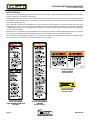
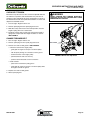
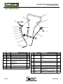
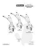
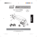
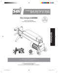
OPERATING INSTRUCTIONS &
Parts EXPLOSIONS
FRONT TINE ROTOTILLERs
Model 3300V
ARDISAM
.com
GetEarthquake.com
OM3300v
Rev. 03/23/09
© 2009 Ardisam, Inc.
All Rights Reserved. Printed in USA.
OPERATor INSTRUCTIONS and parts
Front Tine Models 3300V
INTRODUCTION
Thank You . . .
for purchasing an Earthquake® forward rotating front tine rototiller
from Ardisam, Inc. We have worked to ensure that this front tine
rototiller meets high standards for usability and durability. With proper
care, your rototiller will provide many years of service. Please take the
time to read this manual carefully to learn how to correctly operate
and maintain your rototiller. This manual should be considered a
permanent part of your rototiller. Due to continuous effort to perfect our
product, certain procedures and specifications are subject to change
without notice. Congratulations on your investment in quality.
CONTENTS
Registration...................................................................................... 3
Safety............................................................................................... 4
Unpacking and Assembly................................................................. 7
Features........................................................................................... 8
Controls............................................................................................ 9
Operation........................................................................................ 10
Maintenance & Storage.................................................................. 12
Troubleshooting & Repair............................................................... 16
Notes.............................................................................................. 17
Parts Explosions............................................................................. 18
REGISTRATION
Record your model number and serial number in the space provided
for easy reference. Fill out and mail the registration card located in your
parts packet. Warranty is valid only if your completed registration card
is received by Ardisam, Inc., within two weeks of the purchase date.
Model Number
Serial Number
Engine Serial Number
Date of Purchase
Place of Purchase
800-345-6007
Page GetEarthquake.com
OPERATor INSTRUCTIONS and parts
Front Tine Models 3300V
SAFETY
! DANGER
OWNER’S RESPONSIBILITY
Accurate assembly and safe and effective use of the rototiller is the
owner’s responsibility.
• Read and follow all safety instructions.
DANGER INDICATES a serious injury or fatality will result if the safety instructions that follow this signal word are
not obeyed.
• Carefully follow all assembly instructions.
• Maintain the tiller according to directions and schedule included
in this Earthquake operator’s manual.
• Ensure that anyone who uses the tiller is familiar with all
controls and safety precautions.
SPECIAL MESSAGES
Your manual contains special messages to bring attention to potential
safety concerns, machine damage as well as helpful operating and
servicing information. Please read all the information carefully to avoid
injury and machine damage.
NOTE: General information is given throughout the manual
that may help the operator in the operation or service of the
machine.
! WARNING
WARNING INDICATES a serious injury or fatality could result if the safety instructions that follow this signal word are
not obeyed.
! CAUTION
CAUTION INDICATES YOU CAN OR YOUR EQUIPMENT CAN BE HURT IF THE SAFETY INSTRUCTIONS THAT FOLLOW THIS SIGNAL WORD ARE
NOT OBEYED.
IMPORTANT SAFETY PRECAUTIONS
Please read this section carefully. Operate the tiller according to
the safety instructions and recommendations outlined here and inserted throughout the text. Anyone who uses this tiller must read the
instructions and be familiar with the controls. Your tiller is equipped
with a safety device that enables you to stop the tines quickly in an
emergency. Learn how the drive safety control lever operates and
how to control the tiller at all times.
This symbol points out important safety instructions
which if not followed could endanger your personal
safety. Read and follow all instructions in this manual
before attempting to operate this equipment.
• Do not allow children to operate this rototiller. Keep small children away
from the area being tilled. Do not allow adults to operate the tiller without
proper instruction.
Preparation
• Dress appropriately when operating the tiller. Always wear sturdy
footwear. Never wear sandals, sneakers, or open shoes, and never
operate the tiller with bare feet. Do not wear loose clothing that
might get caught in moving parts.
• Carefully inspect the area to be tilled and remove all foreign objects.
Do not till above underground water lines, gas lines, electric cables,
or pipes. Do not operate the tiller in soil with large rocks and foreign
objects which can damage the equipment.
IMPORTANT
IMPORTANT INDICATES HELPFUL INFORMATION
FOR PROPER ASSEMBLY, OPERATION, OR
MAINTENANCE OF YOUR equipment.
! WARNING
You must read, understand and comply with
all safety and operating instructions in
this manual before attempting to setup
and operate your rototiller.
Failure to comply with all safety and
operating instructions can result in loss
of machine control, serious personal
injury to you and/or bystanders, and risk
of equipment and property damage. The
triangle in the text signifies important
cautions or warnings which must be
followed.
CALIFORNIA PROPOSITION 65 WARNING
Engine exhaust from this product
contains chemicals known to the State
of California to cause cancer, birth
defects, or other reproductive harm.
• Disengage all clutches and leave all control levers in the neutral
position before starting the engine.
• Handle fuel with care; it is highly flammable.
a. Use an approved fuel container.
b. Never add fuel to a running engine or hot engine.
Page 800-345-6007
GetEarthquake.com
OPERATor INSTRUCTIONS and parts
Front Tine Models 3300V
c. Fill fuel tank outdoors with extreme care. Never fill fuel tank indoors.
d. Replace gasoline cap securely and clean up spilled fuel before restarting.
• Never attempt to make any adjustments while the engine is
running.
Operation
• Do not operate the tiller under the influence of alcohol or
drugs.
IMPORTANT
The right and left sides of your
rototiller are determined from
the operating position as you
face the direction of forward
travel.
Engine is shipped from factory
without oil.You must add engine
oil before starting engine.
• Never operate the tiller without guards, covers, and hoods in
place.
Maintenance and storage
• Keep hands, feet, and clothing away from rotating parts. Keep
clear of tiller tines at all times.
• Keep machine, attachments, and accessories in safe working
condition.
• Tines rotate when tiller is engaged, tines rotate when the drive
safety control lever is pulled down. Releasing the drive safety
control lever to neutral stops the tines.
• Check shear bolts and engine mounting bolts at frequent
intervals for proper tightness to be sure the equipment is in
safe working condition.
• Use extreme caution when operating on or crossing gravel
drives, walks, or roads. Stay alert for hidden hazards or
traffic.
• To prevent accidental starting, always disconnect and secure
the spark plug wire from the spark plug before performing tiller
maintenance.
• After striking a foreign object, stop the engine, remove the
wire from the spark plug, thoroughly inspect the tiller for
any damage, and repair the damage before restarting and
operating the tiller.
• Never run the engine indoors. Exhaust fumes are deadly.
• If vegetation clogs the tines, STOP THE ENGINE AND
DISCONNECT THE SPARK PLUG WIRE before removing
vegetation by hand.
• Engine muffler will be hot from operation. Do not touch it with
bare skin or a severe burn may result.
• Always allow muffler to cool before filling fuel tank.
• Never store equipment with gasoline in the tank inside a closed
building where fumes may reach an open flame or spark. Allow
the engine to cool before storing in any building.
• Always refer to the operator’s guide instructions for important
details if the tiller is to be stored for an extended period.
• If the unit should start to vibrate abnormally, stop the engine
and check immediately for the cause. Vibration is generally a
warning of trouble.
• Do not run the engine indoors; exhaust fumes are deadly.
• Do not overload the machine capacity by attempting to till too
deep at too fast a rate.
• Never allow bystanders near the unit.
• Never operate the tiller without good visibility or light.
• Be careful when tilling in hard ground. The tines may catch in
the ground and propel the tiller forward. If this occurs, let go
of the handlebars and do not restrain the machine.
• Take all possible precautions when leaving the machine
unattended. Disengage all control levers, stop the engine,
wait for all moving parts to stop, and make certain guards
and shields are in place.
• When leaving the operating position for any reason:
- shut off the engine.
- wait for all moving parts to stop.
800-345-6007
Page GetEarthquake.com
OPERATor INSTRUCTIONS and parts
Front Tine Models 3300V
SAFETY DECALS
This rototiller unit has been designed and manufactured to provide you with the safety and reliability you would expect from an industry
leader in outdoor power equipment manufacturing.
Although reading this manual and the safety instructions it contains will provide you with the necessary basic knowledge to operated
this equipment safely and effectively, we have placed several safety labels on the tiller to remind you of this important information
while you are operating the unit.
These important safety labels are illustrated below, and are shown here to help familiarize you with the location and content of the
safety messages you will see as you perform normal tilling operations. Please review these labels now. If you have any questions
regarding their meaning or how to comply with these instructions, reread the complete safety instruction text on the preceding pages,
or contact your local dealer.
Should any of the safety labels become unreadable because of being worn, faded, or otherwise damaged during the use of your tiller,
please use the part number information provided to order a replacement label from your local authorized dealer.
The safety labels are easily applied, and will act as a constant visual reminder to you, and others who may use the equipment. Follow
the safety instructions necessary for safe, effective operation of your rototiller.
Part No. LBL3300PP
HOOD WARNING
Rear Hood Decal
Part No. LBL3100D
CLUTCH ENGAGE
Handlebar Decal
Part No. LBL3300DGR
TINES DANGER/OPERATION
Hood Decal
Part No. LBL3300WARN
WARNING
Pivot Mount Decal
Page 800-345-6007
GetEarthquake.com
OPERATor INSTRUCTIONS and parts
Front Tine Models 3300V
Unpacking and Assembly
IMPORTANT
unpack tiller & assemble
1. Open top of carton and remove handlebar assembly.
2. Find parts bag (part number 3319). Parts bag for 3300V contains:
2- M8 x 60 bolts
2- hand knobs
1- 10 x 50 clevis pins
6- M5 x 12 bolts
6- M5 nuts
1-depth regulator lever
3. Cut open top of carton and remove machine:
a. Assemble top handlebar over lower loop. Put M8 x 60 bolts through both holes from inside out. Put on M8 spring wash
ers and tighten with hand knobs. See Figure 1.
b. Assemble hood extensions using 6- M5 x 12 bolts plus 6- M5 nuts. See Figure 2.
c. Assemble tines to unit. Sharp edges of tines will be away from the operator at top or face down.
At front of machine. Use 2- M10 x 50 clevis pins plus 2- 2.5 x 51.25 hair pins. See Figure 3.
d. Install wheel assembly to machine using 2- M10 x 20 bolts with 2-M10 external toothed lock washers. See Figure 4.
The right and left sides of your
rototiller are determined from
the operating position as you
face the direction of forward
travel.
Engine is shipped from factory
without oil.You must add engine
oil before starting engine.
! CAUTION
DO NOT TRY TO LIFT THE ROTOTILLER FROM THE
CARTON.
install depth regulator lever
1. Install the depth regulator lever through hole in bracket from the
bottom up with curve to rear of unit and secure with 4 x 94 hair
pin. SEE FIGURE 6 ON PAGE 9.
Fill engine CRANKCASE
1. Add oil according to engine manual. Do not overfill. Use a clean,
high quality detergent oil. Container must be marked A.P.I. Service
SF - SJ. Use no special additives with recommended oils. Do not
mix oil with gasoline. Oil level must be full. Check the oil level
by removing oil fill plug. Oil level should be up to the bottom of the
fill plug opening.
Figure 1
2. Always check oil level before starting engine. Refer to engine
manual for capacity and type of oil to use.
Figure 2
Figure 3
800-345-6007
Figure 4
Page GetEarthquake.com
OPERATor INSTRUCTIONS and parts
Front Tine Models 3300V
Features (3300V)
drive safety control lever
throttle
control lever
adjustable forward cable
adjustable
handlebar height
adjustable depth
regulator lever
adjustable height
transport wheels
front safety
belt cover
replaceable bolo tines
Transport Position
Operating Position
Page 800-345-6007
GetEarthquake.com
OPERATor INSTRUCTIONS and parts
Front Tine Models 3300V
controls
! CAUTION
Drive SAFETY Control Lever
BELT TENSION ADJUSTMENT
This information is provided here only to
introduce the controls. DO NOT START THE
ENGINE AT THIS TIME. Starting and operating
instructions are given on page 10. Please
read this section and all operating and
safety instructions before starting your
tiller.
Proper belt tension is critical to good performance. After 1/2 hour of
operation, all cables may have to be adjusted due to initial stretch.
Thereafter, check tension after every 2 hours of operation.
• As a safety precaution, the drive safety
control lever will not lock in the
forward position.
To increase belt tension: See Figure 5.
• To stop the tines at any time release the
drive safety control lever.
Engage tines into forward, releasing returns machine to neutral.
Pulling down on drive safety control lever engages the tines. Releasing
the drive safety control lever disengages the tines to a neutral
position.
1. Loosen upper jam nut. Turn nut up cable in 1/8” increments.
2. Tighten lower jam nut.
3. Check adjustment. Adjustment should not allow tines to direct
drive when drive control lever is in neutral position.
This procedure can be repeated until conduit adjustment bolts have
no more adjustment left. If no more adjustment can be made, belt
may have to be replaced.
DEPTH REGULATOR LEVER
Tilling depth is controlled by the height of the depth regulator lever.
See Figure 6.
! WARNING
ENGINE SHOULD BE OFF BEFORE ADJUSTING
ANY CONTROLS.
Do not adjust tilling depth unless drive
safety control lever is released to the
neutral position.
To adjust tilling depth.
1.Remove hair pin.
2.Raise the depth regulator lever to position tines at chosen tilling
depth.
3.Align hole in depth regulator lever with hole in depth regulator
bracket and replace hair pin.
drive safety control lever disengaged
1/4” stretch
upper jam nut
lower jam nut
forward cable
adjustable depth
regulator lever
FIGURE 5-Model 3300V Handlebar
800-345-6007
FIGURE 6-Depth Regulator Lever
Page GetEarthquake.com
OPERATor INSTRUCTIONS and parts
Front Tine Models 3300V
OperatioN
IMPORTANT
PRE-START INSPECTIOn
1. Make sure all safety guards are in place and all nuts and bolts are secure.
2. Check oil level in engine crankcase. See your engine manual for
procedure and specifications.
3. Inspect air cleaner for cleanliness. See your engine manual for
procedure.
4. Check the fuel supply. Fill the fuel tank no closer than 1 inch from top of tank to provide space for expansion. See your engine
manual for fuel recommendations.
5. Be sure spark plug wire is attached and spark plug is tightened securely.
6. Check position of wheels.
7. Check depth regulator lever position.
8. Examine underneath and around engine for signs of oil or fuel
leaks.
9. Inspect fuel hoses for tightness and fuel seepage.
10.Look for signs of engine damage.
11.Remove excessive debris from muffler area and recoil starter.
START-UP
The controls required to start and run the rototiller are located on the
handlebar.
A more detailed description of engine operation and all related
precautions and procedures can be found in the engine manufacturer’s
manual that accompanies each tiller.
Cold Starts
1. Move throttle lever to full choke position. SEE FIGURE 7.
2. Pull starting rope out slowly one time and allow to return
normally.
3. Pull starting rope out rapidly, and allow rope to return normally.
4. When engine starts, gradually move choke lever to run position
and increase throttle speed to “FAST” position.
Restarting A Warm Engine
Engine is shipped from factory without oil.
YOU MUST ADD ENGINE OIL BEFORE STARTING
ENGINE.
Practice operating the controls and
tiller with tines out of ground before
beginning to till. It is important that you
know how to use the tiller properly, keep
control at all times, stop the tines and
wheels from turning, and stop the engine
if necessary. If you do not know how to
do these things, read the Controls and
Safety sections before proceeding.
! CAUTION
Please do not start your tiller until you
have read the Manual that came with your
engine, and the sections in this manual
titled Controls and Safety. If you have
read these, follow the steps below to
start your tiller. Always perform this
pre-start checklist before starting the
engine.
! WARNING
Gasoline is highly flammable and must
be handled with care. Never fill the tank
when the engine is hot or running. Always
move outdoors to fill the tank.
Temperature of muffler and near by areas
may exceed 150° F. Avoid these areas.
Do not move choke control to CHOKE to
stop engine. Backfire or engine damage
may occur.
TO STOP THE ENGINE AT ANY TIME, MOVE THROTTLE CONTROL TO THE OFF POSITION. To stop
tines at any time, release drive safety
control lever to the neutral position.
Always release drive safety control
lever to the neutral position before
adjusting the depth of the regulator
lever.
Restarting an engine that is already warm from previous running does
not normally require use of the choke.
1. Move throttle lever to run fast position.
2. Pull starting rope out rapidly until engine starts. Allow rope to return
normally. Repeat until engine starts.
Figure 7
Page 10
800-345-6007
GetEarthquake.com
OPERATor INSTRUCTIONS and parts
Front Tine Models 3300V
Operating Speed
! WARNING
For normal tilling, set the throttle lever to “fast”.
SHUTTING DOWN
To stop the engine at any time, move throttle control to the stop position.
To stop tines at any time, release the drive safety control lever to the
neutral position.
Tilling
Extreme caution must be taken in selecting tilling depth. If you attempt to till
too deeply for soil conditions, that is,
with the drag stake in too high a position,
loss of control could result.
If removing material from the tines by
hand, stop engine and remove spark plug
wire first.
1. Adjust the depth regulator lever to desired tilling depth.
NOTE: Raise depth regulator lever up one hole at a time,
testing tiller operation after each raise. Raising depth regulator
lever too high can result in loss of control of tiller!
2.Move the throttle control to fast.
3.Place the tiller in motion by pushing down on the drive safety control
lever--this will engage the tines.
! DANGER
Engine and surrounding parts become
extremely hot during normal use and will
cause serious burn injuries if touched
before the engine has cooled.
Allow engine to cool completely before
touching these hot surfaces.
Always keep hands and feet clear of
rotating machine parts.
800-345-6007
Page 11
GetEarthquake.com
OPERATor INSTRUCTIONS and parts
Front Tine Models 3300V
MAINTENANCE AND STORAGE
MAINTENANCE SCHEDULE
Your rototiller has been designed and produced by the industry’s leading manufacturer of outdoor power equipment to provide you
with years of reliable operation.
Keeping your tiller in top running condition will prolong its life, and help you obtain optimum performance.
Please read this normal care schedule, and note the recommended care operating intervals to extend the life of your unit.
Page
Before
Each Use
Change belt tension
13
X
Change forward belt
13
Engine maintenance
14
x
x
Check or fill engine crankcase
14
x
2
Clean tine axle shaft
14
x
Lubrication
14
x
-
1
Maintenance Operation
Check throttle control adjustment
50 hours or
Every Season
x
EM = See engine manual
1 Adjust throttle control after first 3 hours of operation or if engine is hard to start or run-on occurs.
2 Change oil after first 5-8 hours of use, then after every 50 hours or every season. Change oil every 25 hours when operating under heavy load or in high temperatures.
SERVICING THE ROTOTILLER
The following information will help you make the necessary checks
and perform the procedures required to follow the normal care
recommendations made for your rototiller unit.
! WARNING
To prevent accidental starting:
If you prefer, your local authorized dealer can make these checks and
perform the required procedures for you.
Engine must be turned off and cool, and spark
plug wire must be removed and secured from
spark plug before checking and adjusting engine
or equipment.
Page 12
800-345-6007
GetEarthquake.com
OPERATor INSTRUCTIONS and parts
Front Tine Models 3300V
Check Belt Tension
Belt tension may decrease over time. It must be adjusted within the
first half hour of operation, and checked after every two hours of
operation. Proper adjustment will assure long belt life. Too much or
too little belt tension will cause premature belt failure. To check and
adjust the forward belt tension:
! WARNING
Check forward belt tension regularly.
Too much or too little tension will cause
premature belt failure.
1. Turn off engine. Engine must be cool.
2. Remove spark plug wire from spark plug and secure.
3. With drive safety control lever in the neutral position, measure
length of spring when in its relaxed state.
4. Pull down on drive safety control lever and measure length of
spring when compressed. Ideal length would be 1/4” shorter.
see figure 5.
Change Forward Belt
1.Turn off engine. Engine must be cool.
2.Remove spark plug wire from spark plug and secure.
BELT GUARDS
3.Remove front and rear belt guards. see figure 8.
• remove the belt from the engine pulley:
- gently pull the engine recoil rope to rotate the pulley.
- with the pulley turning, force the belt out of the groove.
- slide the belt free of the engine pulley.
Figure 8-Belt Tension Adjustment
- pull the belt down and out of the way.
- push the belt forward and out front of machine.
• install new belt:
- place belt in transmission pulley groove.
- gently pull the engine recoil rope to rotate the pulley while forcing the belt into the groove.
4.Replace front and rear belt guards.
5.Attach spark plug wire.
800-345-6007
Page 13
GetEarthquake.com
OPERATor INSTRUCTIONS and parts
Front Tine Models 3300V
Engine Maintenance
Refer to the engine manual included in your parts packet for
information on engine maintenance. Your engine manual provides
detailed information and a maintenance schedule for performing the
following tasks:
1. Check oil level before each use or after every 8 hours of
operation.
2. Change oil after first 5-8 hours of operation. Change oil while engine
is warm. Refill with new oil of recommended grade.
IMPORTANT
Engine is shipped from factory without oil.
You must add engine oil before starting
engine.
Engine can overheat and become damaged
if debris blocks the cooling system or
rotating screen.
Never run engine without complete air
cleaner installed on engine.
4. Check spark plug yearly or every 100 hours of operation.
5. Service air cleaner.
! CAUTION
6. Keep engine and parts clean.
7. Check engine and equipment often for loose nuts and bolts, keep
these items tightened.
Check or Fill Engine Crankcase
1. Add oil according to engine manual. Do not overfill. Use a clean,
high quality detergent oil. Container must be marked A.P.I. Service
SF - SJ. Use no special additives with recommended oils. Do not
mix oil with gasoline. Oil level must be full. Check the oil level
by removing oil fill plug. Oil level should be up to the bottom of the
fill plug opening on most engines.
Do not operate tiller before reading
the engine manual provided in the parts
packet.
! WARNING
Temperature of muffler and near by areas
may exceed 150° F. Avoid these areas.
2. Always check oil level before starting engine. Refer to engine
manual for capacity and type of oil to use.
Clean tine axle shaft
1. Turn off engine. Engine must be cool.
2. Remove spark plug wire and secure from spark plug.
3. Remove all vegetation, string, wire, and other material that may
have accumulated on the axle between the inside set of tines and
the seal on the transmission housing.
4. Replace spark plug wire.
Lubrication
Proper lubrication of moving mechanical parts is critical for proper care
and maintenance. Oil the moving parts using a 30 weight oil.
check tiller transmission grease
grease out, high
grease port
NOTE: Tiller transmission is shipped from factory with the proper
amount of grease. (Suggestd grease ML365)
To add grease, remove both high and low grease ports. Inject grease
in bottom until you see some at the top hole, transmission is now full.
see figure 9.
grease in, low
grease port
Figure 9
Page 14
800-345-6007
GetEarthquake.com
OPERATor INSTRUCTIONS and parts
Front Tine Models 3300V
storage
! WARNING
Prepare for Storage
Follow the steps below to prepare your tiller for storage. Read your
engine manual for detailed instructions on preparing the engine for
storage.
1. Protect wheels and axles from rust:
Do not store tiller in an unventilated
area where fuel fumes may reach flame,
sparks, pilot lights or an ignited object.
Drain fuel outdoors away from any
ignition sources. Use only approved fuel
containers.
- Coat the axles lightly with axle grease.
2. Drain fuel system completely following engine manufacturer’s
instructions or add fuel stabilizer to prevent fuel from gumming up
during extended storage period.
3. While engine is still warm, drain the oil from the engine. Refill with
fresh oil of the recommended grade.
4. Clean external surfaces, engine and cooling fan.
5. Remove spark plug, pour one ounce of SAE 30 oil into spark plug
hole.
6. Plug hole and pull starter cord slowly to distribute oil evenly in
cylinder head area.
7. Reinstall spark plug.
8. Transport unit to a suitable storage location. If you have chosen to
use a fuel stabilizer and have not drained the fuel system, follow all
safety instructions storage precautions in this manual to prevent the
possibility of fire from the ignition of gasoline fumes. Remember,
gasoline fumes can travel to distant sources of ignition and ignite,
causing risk of explosion and fire.
9. If there is any possibility of unauthorized use or tampering, remove
the spark plug and store it in a safe place before storing the rototiller
unit. Be sure to plug the spark plug hole to prevent foreign material
from entering.
800-345-6007
Page 15
GetEarthquake.com
OPERATor INSTRUCTIONS and parts
Front Tine Models 3300V
Troubleshooting and Repair
! WARNING
Troubleshooting Guide
Practice safety at all times. Engine must be
turned off and allowed to cool, and spark
plug wire must be disconnected and secured
before attempting any maintenance or
repair.
Failure to comply with this safety requirement
can result in serious personal injury to you
or bystanders.
While normal care and routine maintenance will extend the life of
your rototiller, prolonged or constant use may eventually require
that service be performed to allow it to continue operating properly.
The troubleshooting guide below lists the most common problems,
causes and remedies.
Problem
Remedy/ActioN
Engine will not start
• Add gas to gas tank.
• Connect spark plug wire to spark plug
• Throttle must be positioned at choke for a cold start
Engine runs rough, floods during operation
• Clean or replace air cleaner
Engine is hard to start
•
•
•
Drain old fuel and replace with fresh. Use gas stabilizer at end of season
Make sure spark plug wire is securely attached to spark plug
Drive safety control lever must be released to neutral to start the engine
Engine misses or lacks power
•
•
•
•
•
Raise the tines for shallow tilling by raising the depth regulator lever
Clean or replace air cleaner
Improper carburetor adjustment, take to authorized engine service center
Replace spark plug and adjust gap
Drain and refill gas tank and carburetor
Engine will not stop when throttle control is positioned at stop • See engine manual to check and adjust throttle linkage
Tiller moves forward during starting
• Drive safety control lever must be released to neutral to start the engine
Tiller is difficult to control when tilling
(machine jumps or lurches forward)
• Lower engine speed in hard ground
• Raise the tines for shallower tilling by lowering the depth regulator lever
Belts squeal in forward operation
•
•
•
•
•
Excessive heat build up in transmission/tine area during tilling
• Remove vegetation
• Check transmission fluid and fill if needed
Turn engine off and allow muffler to cool
Disconnect spark plug wire and secure from spark plug
Release drive safety control lever to neutral
Adjust engage cable
Replace spark plug wire
Page 16
800-345-6007
GetEarthquake.com
OPERATor INSTRUCTIONS and parts
Front Tine Models 3300V
NOTES
_____________________________________________________________________________________________
_____________________________________________________________________________________________
_____________________________________________________________________________________________
_____________________________________________________________________________________________
_____________________________________________________________________________________________
_____________________________________________________________________________________________
_____________________________________________________________________________________________
_____________________________________________________________________________________________
_____________________________________________________________________________________________
_____________________________________________________________________________________________
_____________________________________________________________________________________________
_____________________________________________________________________________________________
_____________________________________________________________________________________________
_____________________________________________________________________________________________
_____________________________________________________________________________________________
_____________________________________________________________________________________________
_____________________________________________________________________________________________
_____________________________________________________________________________________________
_____________________________________________________________________________________________
_____________________________________________________________________________________________
_____________________________________________________________________________________________
_____________________________________________________________________________________________
_____________________________________________________________________________________________
_____________________________________________________________________________________________
_____________________________________________________________________________________________
_____________________________________________________________________________________________
_____________________________________________________________________________________________
_____________________________________________________________________________________________
_____________________________________________________________________________________________
800-345-6007
Page 17
GetEarthquake.com
OPERATor INSTRUCTIONS and parts
Front Tine Models 3300V
3300V Handlebar parts
3
5
10
4
13
1
8
12
6
15
9
2
14
11
7
REF.
NO.
PART #
DESCRIPTION
1
3255
THROTTLE CONTROL
1
2
3251
THROTTLE CABLE
1
3
3210
HANDLEBAR WELDMENT UPPER
1
4
3262
DEADMAN FRONT TINE
WELDMENT
1
5
3170
NUT-PUSH, 3/8” W/SAFETY
WASHER ZN
6
3268
LINK, 5 3/4 LONG
7
3208
CABLE W/FERREL
QTY.
REF.
NO.
PART #
DESCRIPTION
8
53620
SPRING COMPRESSION FORWARD
ARM RT
1
9
3317
KNOB, PLASTIC M8 BLACK FOUR
STAR
2
10
W1265V0913
NUT, M6 NYLOCK GRADE 8.8
1
1
11
3256
BOLT, M8 X 1.25 X 60 HHCS GR8.8
ZN
2
1
12
3254
BOLT, M6 X 1.0 X 60 CRG GR8.8 ZN
1
1
13
3248
NUT, M5 X 0.8 FNYLK GR8.8 ZN
1
14
3253
WASHER, SPRING LOCK M8 8.5 X
14.8 X 1.9 ZN
2
15
4620
NUT, M8 X 1.25 HJAM GR8.8 ZN
2
Page 18
QTY.
800-345-6007
GetEarthquake.com
OPERATor INSTRUCTIONS and parts
Front Tine Models 3300V
3300V motor mount & Hood parts
15
16
35
49
9
38
46
48
17
2
36
4
12
13
40
5
1
18
6
39
3
8
37
10
31
7
11
20
30
41
27
25
34
43
21
45
32
24
23
33
44
28
14
42
19
47
29
22
26
PARTS BAG
50
800-345-6007
Page 19
GetEarthquake.com
OPERATor INSTRUCTIONS and parts
Front Tine Models 3300V
3300V motor mount & Hood parts
REF.
NO.
PART #
DESCRIPTION
QTY.
REF. PART #
NO.
DESCRIPTION
1
3201
FRAME
2
3249
HOOD
3
3233
BUMPER FRAME TUBE
1
4
3293
FRAME RAIL, U-SHAPE RIGHT
5
3292
6
1
26
3259
LEVER DEPTH REGULATOR
1
1
27
3257
HAIR PIN COTTER PIN 4MM DIA.
X 94MM LNG
1
1
28
3287
HUB CAP
2
FRAME RAIL, U-SHAPE LEFT
1
29
3289
2
W1265V0900
NUT, M8 NYLOCK ZINC GR8.8
8
WASHER LOCK EXT., TOOTH M10
10.5 X 18 0.9 THK
7
3301
SPRING SHIFT ARM
1
30
3211
PLATE SHIFT ARM
1
8
3286
HOOD EXTENSION
2
31
3299
SPACER, SHIFT ARM
1
9
3224
PULLEY ENGINE
1
32
3213
SLEEVE SPACER IDLER PULLEY
1
10
3212
BELT GUARD, FRONT
1
33
3303
PULLEY IDLER W/BEARINGS
1
11
3291
BELT GUARD, REAR
1
34
3248
NUT, M5 X 0.8 FNYLK GR8.8 ZN
8
12
3231
BOLT, M6 X 1.0 X 12 SFHCS GR8.8
ZN T/T
8
35
3313
SET SCREW M8 X 1.25 X12 SCP
GR 8.8
1
13
3246
WASHER, PLASTIC 9MM X 22MM X
2MM
4
36
3250
BOLT, M5 X 0.8 X 12 PPHMS
GR8.8 ZN
8
14
3243
BELT, 7PJ406
1
37
3298
BOLT CAP 8MM
1
15
31321
ENGINE VERT. SHAFT 6HP
1
38
3294
BOLT, M8 X 1.25 X 260 HHCS
GR8.8 ZN
2
16
3209
HANDLEBAR LOOP LOWER
1
39
3244
3316
BOLT, M8 X 1.25 X 40 HHFCS GR8.8
ZN
2
BOLT, M8 X 1.25 X 30 HHFCS
GR8.8 ZN
3
17
40
3247
3245
WASHER, M8 8.4MM X 24MM X
2.2MM ZN
3
BOLT, M8 X 1.25 X 45 HHFCS
GR8.8 ZN
4
18
41
64291
NUT, FLANGE M8
1
19
3282
TAIL MOUNT
1
42
W1265V0900 NUT, M8 X 1.25 HNYLK GR8.8 ZN
1
20
3281
SPRING EXT. 80LNG X 10 OD X 1.5
WIRE STEEL HK END
1
43
W1265V0903 NUT, M10 HNYLK GR8.8 ZN
2
21
W1265V0904
BOLT, M8 X 20 HHCS ZINC GR8.8
1
44
3288
BOLT, M8 X 1.5 X 60 HHFCS
GR8.8 ZN
2
22
3285
BRACKET WHEELS
1
45
2431
4
23
3283
WHEEL 198MM DIA. X 42MM WD
2
WASHER, FLAT M10 10.5 X 20 X 2
THK GR8.8 ZN
24
3284
BUSHING WHEEL
2
46
400024
3
25
3225
CARRIAGE MOUNT
1
WASHER, FLAT M8 8.4 X 16 X 1.6
THK GR8.8 ZN
47
3238
BOLT, M10 X 1.5 X 20 HHCS
FR8.8 ZN
2
48
64366
BOLT, M8 X 1.25 X 50 HHFCS
GR9.9 ZN
1
49
3318
KEY WOODRUFF 4 X 7.5 DIN6888
1
50
3319
PARTS BAG
1
Page 20
QTY.
800-345-6007
GetEarthquake.com
OPERATor INSTRUCTIONS and parts
Front Tine Models 3300V
tine & transmission PARTS
Kit Parts
20
22
33
19
15
32
12
21
31
8
24
18
1
30
17 23
3
6
13
10
11
5
REF. PART # DESCRIPTION
NO.
1
3228
25
14
QTY.
HAIR PIN COTTER PIN 2.5MM DIA X
51.25MM LNG ZN
2
4
7
16
9
2
29
26
27
28
REF. PART #
NO.
DESCRIPTION
QTY.
17
3241
BOLT, M8 X 1.25 X 12 HHCS GR8.8 ZN
2
18
3296
PIN CLEVIS M10 X 50 X 3.2 HOLE ZN
2
2
3217
SEAL PROTECTOR TINE SHAFT
2
19
3308
WASHER, FLAT M5 5.3 X 10 X 1.0 ZN
2
3
3242
TRANSMISSION CASTING RIGHT
1
20
3307
BOLT, M5 X 0.8 X 8 FHMS GR8.8 ZN
2
4
3218
TRANSMISSION CASTING LEFT
1
21
3309
3223
GEAR BRONZE
1
BEARING RADIAL BALL 6004 20MM X
42MM X 12MM
1
5
6
50268
BEARING 25MM X 47MM X 12MM
2
22
3311
1
7
3219
LIP SEAL FA25 X 40 X 7
2
SPRING PIN M5 X 40MM STEEL
SLOTTED
8
3295
DRIVE SHAFT WORM GEAR
1
23
W1265V0913
NUT, M6 NYLOCK GR8.8
9
9
3216
SLEEVE TINE SHAFT EXTENSION
2
24
3220
1
10
3227
SHAFT TINE
1
BEARING TAPERED ROLLER 30204
20 X 47 X 15.25
11
3226
KEY TINE SHAFT 8 X 7 X 28
1
25
3297
SHIM 26MM X 35MM X 5MM
2
12
3312
BELT GUIDE
1
26
3214
TINE HOLDER WELDMENT
2
13
3229
RIVET TINE SHAFT 8MM DIA X 12MM
LNG
2
27
3234
TINE RIGHT
8
28
3235
NUT, M10 X 1.5 HTPLK GR8.8 ZN
32
14
3221
RETAINING RING EXT 25MM SHAFT
BLK PHOS
2
29
3238
BOLT, M10 X 1.5 X 20 HHCS GR8.8 ZN
32
30
3240
TINE LEFT
8
15
3302
PULLEY TRANSMISSION
1
31
3239
TINE SET LEFT, KIT
1
16
3215
BOLT, M6 X 1.0 X 20MM SCS GR8.8 ZN
9
32
3236
TINE SET RIGHT, KIT
1
33
3315
TRANSMISSION ASSEMBLY, KIT
1
800-345-6007
Page 21
GetEarthquake.com
OPERATor INSTRUCTIONS and parts
Front Tine Models 3300V
NOTES
_____________________________________________________________________________________________
_____________________________________________________________________________________________
_____________________________________________________________________________________________
_____________________________________________________________________________________________
_____________________________________________________________________________________________
_____________________________________________________________________________________________
_____________________________________________________________________________________________
_____________________________________________________________________________________________
_____________________________________________________________________________________________
_____________________________________________________________________________________________
_____________________________________________________________________________________________
_____________________________________________________________________________________________
_____________________________________________________________________________________________
_____________________________________________________________________________________________
_____________________________________________________________________________________________
_____________________________________________________________________________________________
_____________________________________________________________________________________________
_____________________________________________________________________________________________
_____________________________________________________________________________________________
_____________________________________________________________________________________________
_____________________________________________________________________________________________
_____________________________________________________________________________________________
_____________________________________________________________________________________________
_____________________________________________________________________________________________
_____________________________________________________________________________________________
_____________________________________________________________________________________________
_____________________________________________________________________________________________
_____________________________________________________________________________________________
_____________________________________________________________________________________________
Page 22
800-345-6007
GetEarthquake.com
FRONT TINE ROTOTILLERS
1-YEAR Limited Warranty
Terms and Conditions
Ardisam, Inc., a manufacturing company, warrants this Earthquake® FRONT TINE ROTOTILLER to be free from
defects in the material or workmanship for a period of one year from the date of purchase. During the one year warranty
of this product, Ardisam will furnish 100% parts and labor to correct any defect caused by faulty material or workmanship.
Items subject to normal wear and tear, such as belts, batteries, tines, shear bolts and tires, due to the nature of their
function are not covered under this warranty. Any unit used in a commercial application is covered for a period of 90
days after purchase. The engine is covered under a separate warranty issued by the engine manufacturer as stated in
the engine manual.
If warranty work needs to be done, contact your place of purchase or Ardisam, Inc. for an authorized service center
in your area. Ardisam will make the necessary repairs if a service center is not available. To obtain warranty service
and/or replacement instructions, you must have prior approval from Ardisam before shipping your package
to us by calling our customer service department at 800-345-6007 for a return material authorization number
(RMA#). All items must be shipped prepaid. Ardisam, Inc. will at no charge, repair or replace, at their discretion, any
defective part which falls under the conditions stated above.
Ardisam retains the right to change models, specifications and price without notice. This product if used as intended, will
give you years of trouble free service. We hope you will enjoy the quality of our products for years to come.
For replacement parts, phone 800-345-6007 or go online to www.GetEarthquake.com.
This warranty applies to the original owner with a proof of purchase and is not transferable. It supersedes all other warranties either expressed or implied and all other obligations to liabilities on our part. Ardisam, Inc. does not assume, and
does not authorize any other person to assume for us, any liability in connection with the sale of our products.
The warranty applies only to products which have not been subjected to negligent use, misuse, alteration, accident or
repairs made by anyone not certified by Ardisam, Inc. This guarantee is void unless the warranty card is properly filled out
and received by Ardisam, Inc., within 30 days of purchase or go to www.GetEarthquake.com for online registration.
Earthquake
A Division of Ardisam, Inc.
1360 First Avenue; P.O. Box 666
Cumberland, Wisconsin 54829
800-345-6007 · Fax (715) 822-4180
E-mail: [email protected]
Visit www.ardisam.com and discover more innovations that will
benefit you throughout the year.
Earthquake, Division of Ardisam, Inc.
1360 First Avenue; P.O. Box 666
Cumberland, Wisconsin 54829
800-345-6007 · Fax (715) 822-4180
E-mail: [email protected]
GetEarthquake.com