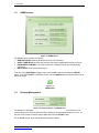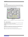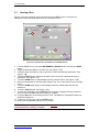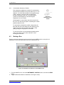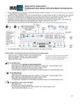
1
Modulus™ Microplate Multimode Reader Operating Manual Part Number 998-9300 Revision 1.6 Turner BioSystems, Inc. and its suppliers own the written and other materials in the Modulus Microplate Reader operating manual. The written materials are copyrighted and protected by the copyright laws of the United States of America and, throughout the world, by the copyright laws of each jurisdiction according to pertinent treaties and conventions. No part of this manual may be reproduced manually, electronically, or in any other way without the written permission of Turner BioSystems, Inc. Modulus™ is a trademark of Turner BioSystems, Inc. All of the trademarks, service marks, and logos used in these materials are the property of Turner BioSystems, Inc. or their respective owners. All goods and services are sold subject to the terms and conditions of sale of the company within the Turner BioSystems, Inc. group that supplies them. A copy of these terms and conditions is available on request. NOTICE TO PURCHASER: The Modulus™ Microplate Reader is for research purposes only. It is not intended or approved for diagnosis of disease in humans or animals. © Turner BioSystems, Inc. 2007 - All rights reserved. Made in the USA Table of Contents 1 Instrument 1.1 Getting Started ................................................................................................................. 2 1.1.1 1.1.2 1.1.3 1.1.4 1.1.5 1.2 Description ............................................................................................................ 2 Precautions ........................................................................................................... 2 Unpacking and Inspection ..................................................................................... 3 Set Up ................................................................................................................... 3 Instrument Overview ............................................................................................. 4 Touch Screen Basics ....................................................................................................... 6 1.2.1 1.2.2 1.2.3 1.2.4 1.2.5 Buttons and Icons on the INSTRUMENT CONTROL Screen............................... 6 Buttons on the READ Screen ................................................................................ 7 Buttons on the RESULTS Screen ......................................................................... 7 Buttons on the TOOLS Screen ............................................................................. 8 Terminology used in Parameter Settings .............................................................. 8 1.3 HOME Screen .................................................................................................................... 10 1.4 Protocol Management ...................................................................................................... 10 1.4.1 1.5 Modifying a Saved Protocol .................................................................................. 11 Instrument Control ........................................................................................................... 12 1.5.1 1.5.2 1.5.3 1.5.4 Plate Mapping ....................................................................................................... 12 Well Selection ........................................................................................................ 13 Selecting Reference Wells .................................................................................... 13 Accessing the Interior of the Instrument................................................................ 13 1.6 Viewing the Data in the RESULTS Screen ..................................................................... 14 1.7 Transferring Data ............................................................................................................. 16 1.8 Repeat Runs ..................................................................................................................... 17 1.8.1 1.8.2 2 ............................................................................................................................... 2 Repeat Runs Parameters ...................................................................................... 17 Viewing Repeat Runs Data on the RESULTS Screen .......................................... 17 Luminescence ............................................................................................................................ 18 2.1 General Information ......................................................................................................... 18 2.2 Microplate Sample Plate Cover ....................................................................................... 18 2.3 PMT Activation ................................................................................................................. 18 2.4 Starting a Run ................................................................................................................... 19 2.5 Kinetic ............................................................................................................................... 20 2.6 Kinetic Parameters ........................................................................................................... 20 2.7 Using a Standard Light Plate .......................................................................................... 21 2.7.1 2.7.2 2.8 Getting Started ...................................................................................................... 21 Running the Standard Light Plate Protocol ........................................................... 21 Luminescence Data.......................................................................................................... 22 2.8.1 2.8.2 Kinetic .................................................................................................................... 22 Ratio Readings ...................................................................................................... 22 Table of Contents 2.9 3 Luminescence Module ..................................................................................................... 22 Fluorescence .............................................................................................................................. 23 3.1 General Information ......................................................................................................... 23 3.2 Optical Wavelenghts and Commonly Used Fluorophores ........................................... 23 3.3 Starting a Run ................................................................................................................... 24 3.4 Switching Fluorescence Optical Kits ............................................................................. 25 3.5 Fluorescence Data ........................................................................................................... 25 3.6 Fluorescence Module....................................................................................................... 25 3.6.1 3.6.2 4 Absorbance ............................................................................................................................... 27 4.1 General Information ......................................................................................................... 27 4.2 Optical Filter Wheels ........................................................................................................ 27 4.2.1 Customizable Absorbance Paddle ........................................................................ 28 4.3 Starting a Run ................................................................................................................... 28 4.4 Ratiometric Assay ............................................................................................................ 29 4.5 Absorbance Data .............................................................................................................. 29 4.5.1 4.6 Ratiometric Data.................................................................................................... 30 Absorbance Module ......................................................................................................... 30 4.6.1 5 Installing the Fluorescence Module....................................................................... 25 Switching Fluorescence Optical Kits ..................................................................... 26 Installing the Absorbance Module ......................................................................... 30 Injector System .......................................................................................................................... 32 5.1 Injector System Components ......................................................................................... 32 5.2 Installation Procedure...................................................................................................... 32 5.3 Injector System Operation............................................................................................... 35 5.3.1 5.3.2 5.3.3 Priming Injectors .................................................................................................... 36 Retrieving Unused Reagents from Injectors (optional) ......................................... 36 Flushing the Injectors after Use ............................................................................ 36 5.4 Cleaning the Injectors ...................................................................................................... 36 5.5 Cleaning the Waste Collection Tray ............................................................................... 37 5.6 Replacing Injector Tips ................................................................................................... 37 5.7 Inserting Injector Tip Assembly ...................................................................................... 37 5.8 Removing or Replacing Inlet and Outlet Tubing ........................................................... 38 5.9 Removing or Replacing Stainless Steel Tubing ........................................................... 38 Table of Contents 6 Accessories ............................................................................................................................... 39 6.1 Curve Fitting Data Analysis Software (9300-970) ......................................................... 39 6.2 Connecting to a PC using External PC Connectivity Kit (9300-971) ........................... 39 6.2.1 6.2.2 6.2.3 6.2.4 6.2.5 6.2.6 6.2.7 6.2.8 6.3 Standard Light Plate (9100-036) ...................................................................................... 42 6.3.1 6.3.2 6.3.3 6.4 7 8 9 General Information............................................................................................... 39 File Locations ........................................................................................................ 40 System Requirements ........................................................................................... 40 Installing Microsoft .NET Framework version 2.0 (x86) ........................................ 40 Installing the Drivers for the Modulus Microplate Reader ..................................... 40 Connecting to a PC Using a USB Cable ............................................................... 41 Connecting to a PC Using an RS_232 Cable ....................................................... 42 Disconnecting from a PC ...................................................................................... 42 Getting Started ...................................................................................................... 42 Running the Standard Light Plate Protocol ........................................................... 42 Changing the Battery............................................................................................. 43 USB Flash Drive (105-9300) ............................................................................................ 43 Tools ............................................................................................................................... 44 7.1 System Information .......................................................................................................... 44 7.2 Event Log .......................................................................................................................... 45 7.3 Sound Control .................................................................................................................. 45 7.4 Setting the Time and Date ............................................................................................... 45 7.5 Updating Software............................................................................................................ 45 7.6 Updating Firmware ........................................................................................................... 46 Instrument Maintenance ............................................................................................................ 47 8.1 General Instrument Care ................................................................................................. 47 8.2 General Cleaning .............................................................................................................. 47 8.3 Touch Screen Care........................................................................................................... 48 8.4 Realigning the Microplate Sample Tray Cover (Luminometer) ................................... 48 Troubleshooting ......................................................................................................................... 49 9.1 Table of Error Messages.................................................................................................. 49 9.2 Table of Common Problems............................................................................................ 51 9.3 Commonly Asked Questions .......................................................................................... 52 9.3.1 9.3.2 PC Connectivity ..................................................................................................... 52 Data Management ................................................................................................. 52 Table of Contents APPENDIX ............................................................................................................................... 53 Appendix A – Specification ....................................................................................................... 53 Appendix B – Warranty and Obtaining Service ...................................................................... 55 Appendix C – Ordering Information ......................................................................................... 57 Appendix D – How to Contact Us ............................................................................................ 59 1 Instrument 1.1 Getting Started 1.1.1 Description Thank you for purchasing the Turner BioSystems, Inc. Modulus™ Microplate Reader. This manual will guide you through the installation, setup and operation of your instrument. The Modulus™ Microplate Reader is an expandable multimode reader with unbeatable performance. Each detection mode has dedicated optics for the highest versatility without sacrifice of performance. The Modulus™ Microplate Reader can be used as a reader dedicated to a single mode or as a multimode reader. As application needs expand, the system can easily accept the add-on of additional detection modes. This modular flexibility allows users to customize the system to fit your laboratory needs. 1.1.2 Precautions Keep the instrument door closed when access to the interior of the instrument is not needed. Leaving the door open for an extended period of time will result in damage to the Photomultiplier Tube (PMT) due to light exposure, dust accumulating on the mechanical parts, or physical damage due to accidentally bumping the open door. IMPORTANT: Do not leave the instrument door open when the instrument is not in use. The Modulus™ Microplate Reader is intended for indoor use only. Wipe up any spills immediately. The reader contains sensitive optical components and precision-aligned mechanical assemblies. Avoid rough handling. The maximum volume recommended for a typical 96-well microplate is 250 µl/well. Do not place more than the recommended volume in each well. Overfilling of wells may lead to spills and/or damage to the instrument. Sample residue can cause the optical head to malfunction. NOTE: Turn the instrument off any time you access the interior, install detection modules, or clean the injectors. www.turnerbiosystems.com 2 1.1.3 Unpacking and Inspection Upon receiving the Modulus™ Microplate Reader, inspect it carefully for any damage to the exterior such as scratches and/or dents. Make certain all accessories are included. Refer to the checklist shipped with the instrument for order-specific items. Save all packaging materials, if possible, in case the instrument needs to be shipped to a service center in the future. 1 11 2 3 8 4 6 7 9 10 5 Figure 1-1: A Complete Modulus™ Microplate System # 1 # 7 2 Content Modulus™ Microplate Reader Instrument Power Line Cord 3 Power Supply Brick, 24V, 60W 9 4 USB Flash Drive, 264MB 10 5 Fluorescence Optical Kits (included with fluorescence module) Luminescence Standard Light Plate (optional) 11 6 1.1.4 8 Content Non-Sterilized 96-Well Microplates (optional starter kit) Waste Collection Tray (included with injector system) Outlet Injector Tube Assembly (included with injector system) DB-15 Serial Cable (included with injector system) Injector System (optional) Set Up CAUTION: Remove all of the foam packaging from inside the instrument before initial power up. Failure to do so may result in damage to the electronics. 1. Place the Modulus™ Microplate Reader on a flat, level surface. Leave at least 7.5 inches (19 cm) of clearance in front of the instrument to allow the instrument door to open without hindrance. Position the instrument so that the touch screen faces outward. 2. Manually open the instrument door and remove the foam packing from inside of the instrument. The packing material is used to secure the optical heads and Microplate Sample Tray during shipping. www.turnerbiosystems.com 3 1 Instrument 3. Plug the power line cord into the power connector on the back panel of the instrument. Plug the power supply brick into a power outlet. For power specifications, refer to Appendix A. 4. Turn the Modulus™ Microplate Reader on. The power switch is located on the back panel next to the power connector. 5. Look for an LED light to come on within one minute. The light is located to the left of the touch screen and indicates when the instrument is initialized. 6. After warming up, the touch screen will activate and default to the HOME screen. If the optional injector system was included with the purchase of the instrument, refer to Section 4 for installation and operation instructions. 1.1.5 Instrument Overview 1 2 3 6 4 7 5 8 Figure 1-2: Front View of Modulus™ Microplate Reader Components Description 1 Color LCD Touch Screen 2 LED Light • • • 3 USB Port 4 Absorbance Module 5 Microplate Sample Tray and Cover 6 Luminescence Module 7 Injector Tip Holder 8 Fluorescence Module and Optical Kit • • When installed, enables the absorbance capability • Holds a 96-well microplate or a Waste Collection Tray The cover reduces crosstalk in luminescence applications When installed, enables the luminescence capability Holds and positions injector tips When installed, enables the fluorescence capability • • www.turnerbiosystems.com Finger touch sensitive Indicates when power is on USB port for data transfer and software updates DO NOT use this port to connect to a computer • • 4 1 Instrument 9 10 11 12 13 Figure 1-3: Back Panel of the Modulus™ Microplate Reader Components 9 RS-232 Port 10 USB Port 11 Injector System Connector 12 Power Connector 13 Power Switch Description • Connects to a PC, 9-pin serial port • Connects to a PC • Exclusively connects the Injector System to the instrument’s 15-pin port • Connects with an AC power supply • Turns the instrument on and off NOTE: Do not connect anything except the injector system to the instrument’s injector system connector. This connector is supplied with 24V of power and may damage your device if used incorrectly. www.turnerbiosystems.com 5 1 Instrument 1.2 Touch Screen Basics A built-in Windows-based PC with a custom interface enables user-friendly control of the Modulus™ Microplate Reader. This all-in-one modular instrument saves bench space while eliminating computer compatibility and maintenance issues. WARNING: Do not touch the LCD screen with any sharp object, pen, pencil, or marker as these may cause permanent damage. Avoid spilling any liquid onto or near the touch screen. The touch screen is sensitive to the light pressure of a fingertip. It is not necessary to use a stylus. To select a function, touch the corresponding button once. To conserve power, sleep mode is activated after 15 minutes without activity or user stimulation of the touch screen. Lightly touch the LCD screen once to reactivate it. 1.2.1 Buttons and Icons on the INSTRUMENT CONTROL Screen • HOME screen • HELP screen • • • Opens and closes the instrument door Changes to a STOP button when a run is in progress Touch the STOP button to cancel a run, if needed • Selects one of the three screens in the INSTRUMENT CONTROL screen • INSTRUMENT STATUS bar (above) • • PLATE icon, visible when a microplate or a Waste Collection Tray detected inside the instrument Icon turns dark when a microplate has been read • • • DETECTION MODE icon A gray icon indicates which detection modules are installed A black icon indicates the active module • Indicates the instrument is ready to begin a run • Indicates one or two injectors are installed www.turnerbiosystems.com 6 1 Instrument • • 1.2.2 1.2.3 Visible when a USB flash drive is detected Icon turns dark when files have been saved to the USB flash drive Buttons on the READ Screen • • DETECTION MODE button Touch the button to toggle between luminescence, fluorescence, and absorbance capabilities • • PROTOCOL button Touch the white text button to see the list of preset and user-defined protocols • • • • PLATE MAPPING button and well selection indicator Touch the button to specify which wells to be read Green wells are selected for reading Gray wells are deselected and will not be read • In Luminescence mode, this button enables KINETIC • In Absorbance mode, the WAVELENGTH button enables single or dual wavelengths • Starts a run • • Activates the PMT before starting a luminescence run PMT activation is required before the first luminescence run of the day • • The SETUP button appears when injectors are connected Prepares the injector(s) for a prime, a flush, and a reverse purge • • • Touch one of the INJECTOR buttons to activate an injector(s) Green indicates the injector is selected Gray indicates the injector is deselected • • Button for keypad entry Used in the USER PROTOCOL screen to enter a protocol name • • DELETE FILES button DELETE PROTOCOL button Buttons on the RESULTS Screen • Displays a list of the 50 most recent results files • Use the UP and DOWN buttons to scroll through the 50 most recent results • Use the RIGHT and LEFT arrow buttons to scroll the wells in columns 1-12 www.turnerbiosystems.com 7 1 Instrument 1.2.4 When viewing Absorbance results, the button toggles between the different data formats: OD, %T, and %A • Toggles through the sets of results generated from repeat runs • PLATE VIEW button shows the full or partial view of the results in a microplate format • • Displays the results as a ratio See Section 2.8.2 for ratio calculations • Copies .csv formatted results files to a USB flash drive • Combines multiple assay runs into one file Buttons on the TOOLS Screen • Displays instrument related information • Transfer instrument event log in .txt format through the USB port to a USB flash drive • Sound on/off • Set time & date • 1.2.5 • • • Port setting for PC Connectivity Visible on the PC version of the software • Use to update software versions • • Switches control of the instrument to a PC Once switched, the PC has full control of the instrument and stores all the data collected on the PC’s hard drive Terminology used in Parameter Settings Integration: The duration of measurement per well ranging from 0.1 to 10 seconds in 0.1-second increments. In assays where noise is much lower than signal, a 1-second integration time will yield the same sensitivity as a 10-second integration time. Unless specified by the assay protocol, a 1-second integration time should be sufficient. Volume: The volume injected into each well ranging from 25 to 200 µl in 5-µl increments. Determine the sample volume per well before selecting an injection volume. Although, the maximum volume of a typical 96-well microplate is 300 µl, the recommended www.turnerbiosystems.com 8 1 Instrument maximum volume per well is 250 µl. Overfilling a well will result in spills and possible damage to the instrument. Delay: The number of seconds between the injection of the reagent and taking a measurement. Setting a delay after the injection will allow flash-type luminescence to fully actualize before a reading. The minimum delay value is 0.5 seconds in 0.1-second increments. Wavelength: Selects one or two Absorbance filters from a list. Optical Kit: Selects a Fluorescence Optical Kit from a list. Reading: The number of times a sample plate is read. The number of reads can be set between 1 and 99. Period: The time interval between readings of the same well ranging from 1 to 120 minutes in 1-minute increments. Prime: The injector system is wetted and filled with the reagent. Flush: The protocol used to clean the injector system after a run. The recommended flush protocol consists of steps for washing with deionized water, 70% ethanol, deionized water, and then air drying. Reverse Purge: The protocol retrieves any unused reagent from the injector system. After a run, this protocol can be used to push the reagent back into the reagent bottle to cut down on waste. Preset Protocols: A set of popular assay protocols preloaded into the instrument for user convenience. These protocols cannot be renamed or deleted. A user-modified version can be saved by touching the USER button on the PROTOCOL screen. User Protocols: Protocols created by the user which can be retrieved later. All parameters including the plate well mapping are saved. These protocols can be modified, renamed, or deleted. www.turnerbiosystems.com 9 1 Instrument 1.3 HOME screen Figure 1-4: HOME Screen The HOME screen contains four options: • NEW PROTOCOL launches the wizard to set up a new protocol. • SELECT PROTOCOL launches the wizard to select pre-programmed protocols from a list. • INSTRUMENT CONTROL is for instrument set up, managing results, and managing the instrument. • HELP TOPICS cover informational topics. From any of the PROTOCOL wizards, return to the HOME screen by touching the CANCEL button. In the INSTRUMENT CONTROL screen, use the HOME button found at the bottom left of the touch screen. Figure 1-5: HOME Button 1.4 Protocol Management Figure 1-6: Protocol Options on HOME Screen The Modulus™ Microplate Reader is designed to be easy-to-use straight out of the box. The protocol wizards are set up to guide the user in setting up all required parameters for a run. At the end of the wizards, insert the sample plate then touch the START button. On the HOME screen, there are two protocol selection buttons: www.turnerbiosystems.com 10 1 Instrument • • NEW PROTOCOL allows the user to create new protocols. Touching this button launches the NEW PROTOCOL wizard. It guides the user through a series of steps to define a protocol. After completing the wizard, the user may save the protocol under the User list of protocols. SELECT PROTOCOL allows the user to retrieve stored protocols. There are two types of stored protocols: Preset and User. The convenient preset protocols are permanently stored on the instrument and cannot be renamed or deleted. However, a modified version of these preset protocols can be saved into the User protocol list. Customized User protocols can be modified, renamed, or deleted at any time. The Modulus™ Microplate Reader has a built-in PC. This gives the instrument its capability for creating, storing, and retrieving user-defined protocols. The Preset protocols contain run parameters for popular third party luminescence, fluorescence, and absorbance assays. 1.4.1 Modifying a Saved Protocol 1. From the HOME screen, touch the INSTRUMENT CONTROL button, then touch the READ button. See Figure 1-7(A). 2. Select a Detection Mode: Luminescence, Fluorescence, or Absorbance. Touch the white text button to toggle between the different modes. See See Figure 1-7(B). 3. Touch the white text button with the protocol name to see the list of available options. See See Figure 1-7 (C). 4. Select a protocol from the Preset or User list and touch the OK button. See Figure 1-8. 5. To modify the desired parameter(s), touch the white numeric button next to the parameter label. Make the desired change then touch the OK button. 6. Touch the PLATE button and select the wells to be read. Green indicates a well is selected and gray indicates a well is deselected. NOTE: Well selections are linked to a protocol. Before running any protocol, always verify the wells to be read. 7. To run the modified protocol under the current name, touch the START button. A B Parameters C Figure 1-8: List of Preset Protocols Figure 1-7: The READ Screen accessed from the INSTRUMENT CONTROL Screen www.turnerbiosystems.com Figure 1-9: User-defined Protocols List 11 1 Instrument 8. To save the modified protocol: 1. Touch the white text button with the protocol name. See Figure 1-7(C). 2. Touch the YES button in the dialog box. 3. To save the protocol under the same name, touch the SAVE button. 4. To save the protocol under a new name, touch the EDIT button. Use the activated keypad to enter the new name and touch the OK button when editing is complete. Then touch the SAVE button to save the renamed protocol. 5. Modified protocols are saved in the User list. See Figure 1-9. To delete a protocol from the User list, highlight the protocol then touch the DELETE button. Protocols from the Preset list cannot be deleted. 1.5 Instrument Control The INSTRUMENT CONTROL screen sets parameters for a run, selects wells on a sample plate, sets up the injector system, manages results, manages system tools, and accesses the interior of the instrument. 1.5.1 Plate Mapping • The instrument reads from A1 to A12, B2 to B12, etc. The read speed is similar in the horizontal and vertical reading direction. Figure 1-7: PLATE MAPPING Screen NOTE: In the PLATE MAPPING screen, green indicates selected wells, gray indicates deselected wells, and REF indicates reference wells (used in absorbance mode). • • • • Touch the PLATE button to open the PLATE MAPPING screen. Select wells to be read. Green indicates a well is selected. Grey indicates a well is deselected. REF indicates a reference well when in absorbance mode. The message box below the wells summarizes the well selection. Touch the OK button to commit changes made in the PLATE MAPPING screen. Touch the X button to cancel any changes made. The wells selected to be read are saved with each protocol setting. When using a saved protocol, make sure the well selection is set to read the intended wells. www.turnerbiosystems.com 12 1 Instrument 1.5.2 Well Selection To select or deselect a well, touch the well to toggle between green and gray colored wells. In absorbance mode, it also toggles to REF for reference wells. To select or deselect a whole row or column, touch the corresponding number or letter. Hold down the button and drag to make continuous changes. When the ALL button is touched, the entire plate toggles between selected and deselected. REMINDER: To run a protocol, at least one microplate well must be selected to be read. 1.5.3 Selecting Reference Wells Reference wells are optional in absorbance mode. The detection mode needs to be on Absorbance to enable this feature. Touch a well to toggle between select, deselect, and reference (Ref). Column and row selection does not have the option to toggle to reference. Readings taken from Reference wells are used as a blank. If more than one well is selected as a Reference, an average of all reference values are applied to each of the readings. Figure 1-8: Well Options as Seen in Absorbance Mode 1.5.4 Accessing the Interior of the Instrument Touch the DOOR button to open and close the instrument door. The Microplate Sample Tray automatically extends and retracts when the DOOR button is touched. If the optional Microplate Sample Tray Cover is installed, it will also automatically open and close with the Microplate Sample Tray. Do not use force to close the Microplate Sample Plate Cover. CAUTION: Do not use force to close the Microplate Sample Plate Cover. Cover will automatically close after touching the DOOR button to close the instrument door. www.turnerbiosystems.com 13 1 Instrument Opening the instrument door while the Microplate Sample Tray is in motion will cause it to stop. When it is necessary to access the instrument interior, turn off the instrument. Manually hold the instrument door open. Do not use the DOOR button. The Microplate Sample Plate Cover may be in the way. IMPORTANT: Close the instrument door immediately after each use! 1.6 Viewing the Data in the RESULTS Screen Figure 1-9: The RESULTS Screen Touch the FILES button to see a list of results files. The files are sorted by the date and time run. Select a file to view. Use the UP and DOWN arrow buttons to scroll through displayed list of results files. The results are displayed in a microplate format in either a full or partial view. Toggle between the two views by touching the PLATE VIEW button between the horizontal arrows. A partial view of the results displays three or six columns of data depending on the protocol. Use the LEFT and RIGHT arrow buttons to scroll through partially viewed results. Touch the Multiplex button to add the next assay run to the current results file. Multiple different technologies can be combined into one results file. For example, run a Fluorescence assay with the blue filter then, press Multiplex and run a Luminescence assay. Data will appear in the same results file as the previous Fluorescence file. The Plus and Minus icons toggle through results files that are linked together from a multiplexing assay run or a repeat plate run. www.turnerbiosystems.com 14 1 Instrument Use the DELETE button to permanently remove unwanted results from the results list. www.turnerbiosystems.com 15 1 Instrument 1.7 Transferring Data Results files are transferred to a PC or Mac via a USB flash drive using the USB port located to the left of the touch screen. The files are exported in a .csv format and are compatible with Microsoft Excel on both Windows and Mac computers. Step-by-step directions follow. 1. To transfer data from the Modulus™ Microplate Reader to an external computer, insert a USB flash drive into the USB port located left of the touch screen. When insertion is detected, an icon depicting a USB flash drive should appear on the INSTRUMENT STATUS bar. 2. Touch the RESULTS button on the INSTRUMENT CONTROL screen. 3. Touch the FILES button and highlight the file to be exported. 4. Touch the USB button under the TOOLS button. 5. Touch the OK button to export only the selected file. Touch the COPY ALL FILES button to export all of the results files. The .csv formatted file(s) will be saved onto the USB flash drive in the folder named Modulus™ Microplate. 6. Move the USB flash drive to your local PC or Mac computer. • For Windows, double-click to open the file in Excel. • For Mac, click to open the file and import the data into Excel. Most USB flash drives are compatible with the Modulus™ Microplate Reader. USB flash drives greater than 1GB may take longer than others to be recognized. Wait a few seconds for the instrument to recognize the USB flash drive. If the problem persists, try a different flash drive. IMPORTANT: Results files can only be transferred from the instrument to a computer via a USB flash drive. Use the USB port on the front of the instrument. After the transfer of results files, backup copies will remain on the internal memory of the Modulus™ Microplate Reader. The 50 most recent files are displayed in the FILES window of the RESULTS screen. www.turnerbiosystems.com 16 1 Instrument 1.8 Repeat Runs Each detection modality has the option to do repeat runs. Injectors cannot be used in this mode. In repeat runs, the entire sample plate is read between each period. 1.8.1 Repeat Runs Parameters Readings: The number of times a sample plate is read. When the number of readings is set to a value between 2 and 99, the period parameter and time estimates are displayed. The time estimate for a plate (located below the readings parameter) is based on the number of wells selected to read. Period: The time difference between readings of the same well. If this value is less than the time estimated to read the plate, a caution message will appear to inform user the actual interval will be longer. The instrument will begin reading A1 (or the first well selected) immediately after completing the last reading of the plate. The actual period time is indicated on the results .csv file when exported to a computer. The range is 1 to 120 minutes in 1-minute increments. Figure 1-10: Parameters for Repeat Runs 1.8.2 Viewing Repeat Runs Data on the RESULTS Screen The results are displayed as a set of data on the RESULTS screen. To view the other sets of data, touch the PLUS button to move forward and touch the MINUS button to move back. All data from repeat runs are saved in one results file. The Modulus™ Microplate Reader saves all captured data to its internal memory. However, when the FILES button is touched, only 50 of the most recent files are visibly listed. To view results files not displayed, touch the USB button to transfer all the files to a USB flash drive and view them on a PC or Mac. Figure 1-11: RESULTS Screen with Repeat Run Data www.turnerbiosystems.com 17 2 Luminescence 2 Luminescence 2.1 General Information • The Luminometer detection wavelength range is 350 to 650 nm. • Microplate Recommendations: - White plates are recommended for general luminescence detection. - Black plates are recommended primarily for bright assays, such as ELISA, but will generally yield decreased sensitivity despite the benefit of having lower background and cross-talk than white plates. - Clear plates are not recommended due to high cross-talk. • For luciferase assays, samples and reagents must be equilibrated to room temperature prior to taking the measurements for optimal light intensity. • For best results, make sure all reagents are as freshly prepared as possible and assay protocols are followed. • To reduce high background noise, keep the interior of the instrument clean. Always flush the injectors after each use and clean up any spills. • To reduce cross-talk from adjacent wells, always use the Microplate Sample Tray Cover. 2.2 Microplate Sample Plate Cover A Microplate Sample Plate Cover is installed on the Microplate Sample Tray with the purchase of the Luminescence module. Its primary purpose is to reduce cross-talk signal from adjacent wells. • 2.3 If any moisture appears on the Microplate Sample Tray Cover, clean the optical lens, the mask, and the interior of the instrument. See Section 1 for general care and cleaning instructions. PMT Activation The Luminescence module uses Photomultiplier Tube (PMT) detection. It requires a 5-minute warm up to ensure consistent results. Activating the PMT prior to preparing the sample plate for reading will reduce the wait time before the run. When the Luminescence mode is selected, an ACTIVATE PMT button is visible in place of the START button. This forces the user to warm up the PMT before initiating a run. After PMT activation begins, the START button will appear. While the PMT is activating, the user can maneuver around the software and select other detection modalities without interfering with the PMT activation. If the instrument door is open for more than one minute, the PMT will deactivate. Parameters and file names can be set during the activation of the PMT. If the START button is touched before the PMT is completely activated, the run will begin immediately after the 5-minute warm up of the PMT. www.turnerbiosystems.com 18 2 Luminescence 2.4 Starting a Run Easy-to-use protocol wizards can be accessed from the HOME screen to set up the run parameters. See Section 1.4 for protocol management. Otherwise, follow the steps below to set up a Luminescence run. A B C D F E Figure 2-1: Luminescence Parameters on the READ Screen 1. From the HOME screen, touch the INSTRUMENT CONTROL button, and then the READ button. See Figure 2-1(A). 2. Toggle the Detection Mode to Luminescence. See See Figure 2-1(B). 3. Touch the white text button to select a protocol or modify the displayed parameters. See See Figure 2-1(C). 4. Touch the PLATE button and select the wells to be read. Green is selected and gray is deselected. See See Figure 2-1(D). 5. Touch the DOOR button to automatically open the instrument door. See See Figure 2-1(E). 6. Place the sample plate on the Microplate Sample Tray. The A1 well must be at the top right corner. 7. Touch the DOOR button again to automatically close the Microplate Sample Tray Cover and retract the sample plate back into the instrument. Do not push down on the Microplate Sample Plate Cover or force it to close. 8. Touch the START button. See See Figure 2-1(F). 9. To name the results file, touch the EDIT button to activate the keypad. Enter the results file name and touch the OK button when editing is complete. 10. Touch the OK button on the dialog screen to save. The Modulus™ Microplate Reader will initialize and begin run. 11. To stop a run at any time, touch the STOP button. 12. Remove the sample plate after the run is complete. REMINDER: To prevent dehydration and spills, remove the sample plate from the equipment when a reading is complete. www.turnerbiosystems.com 19 2 Luminescence 2.5 Kinetic In kinetic mode, the instrument performs multiple reads of a single well with defined frequency over a defined period of time before moving to the next well. The kinetic feature is available in Luminescence mode only. One or both injectors can be used in the Kinetic mode. Each sample reading is taken after the second injection and injection delay. A Figure 2-2: Kinetic Parameters in Luminescence Mode (A) KINETIC Button To activate kinetic mode, touch the KINETIC button located below the PLATE button. See Figure 2-2(A). 2.6 Kinetic Parameters Initial Delay: Delay before the start of the first reading to allow the sample plate to dark-adapt. The range is from 0 to 60 minutes in 1-minute increments. Readings: The number of data points to collect per well. The range is from 2 to 250 in 1-unit increments. Kinetic Interval: The reading frequency. The range is from 0.1 to 60 seconds in 0.1 second increments. A 1 second Kinetic Interval means the readings are taken every 1 second. Well: The time it takes to read one well using the defined parameters. Plate: The time estimated to read the entire sample plate using the defined parameters. www.turnerbiosystems.com 20 2 Luminescence 2.7 Using a Standard Light Plate The optional Standard Light Plate provides a quick way to verify instrument performance. The Standard Light Plate consists of three highly stable light sources which simulate luminescent samples at signal intensity ranging over four logarithmic scales of data. 2.7.1 Getting Started 1. Briefly press the “Start” button on the Microplate Luminometer Light Plate. 2. The “Battery Check” indicator will flash a green light as long as the “Start” button is pressed and the battery has sufficient power. 3. The green light will turn OFF once the “Start” button is released. The light plate is now ON and ready for use. After five minutes it will automatically turn OFF. The builtin timer can be restarted at any time by pressing the “Start” button again. 4. If the green light does not appear while the “Start” button is pressed, replace the battery. See Section 6.3.3. 2.7.2 Running the Standard Light Plate Protocol 1. From the HOME Screen, choose INSTRUMENT CONTROL. 2. From the INSTRUMENT CONTROL Screen, select Luminescence by pressing the DETECTION MODE button. 3. After Luminescence has been selected, press the Luminescence Protocol button and scroll down to Luminescence Light Plate. 4. Load the Standard Light Plate and press the READ button. For additional details regarding the Standard Light Plate, see Section 6.3. www.turnerbiosystems.com 21 2 Luminescence 2.8 Luminescence Data Luminescence data is displayed in Relative Luminescence Units (RLU). 2.8.1 Kinetic Kinetic results are displayed in graphic curve format in the RESULTS screen. To obtain the numeric readings, export the results file to a USB flash drive and transfer it to a computer. See Section 1.7 for transferring data. There will be a single result file for the entire run. The x-axes are displayed in linear time and y-axes are displayed in log RLU scale. The yaxes have a minimum range of 1 log (a result value range of 10). Each well auto adjusts to display the graph in full y-axis scale. 2.8.2 Ratio Readings When two injectors are used in a protocol, two readings are taken for each sample. Results are displayed side-by-side in the corresponding well (partial view) or first reading on top of the second reading (full view). To view a ratio of the two readings, touch the RATIO button. The ratio calculated for luminescence data is different than for absorbance data. The luminescence ratio is calculated as: st Ratio = 1 reading nd 2 reading NOTE: A value of 1E29 indicates saturation of luminescence signal. 2.9 Luminescence Module To add luminescence detection capability to the Modulus™ Microplate Reader, contact the Turner BioSystems Sales Department or a Distributor for information on purchasing and installation of the Luminescence UHS Detection Module. See Appendix C for ordering information. Due to optical and alignment complexities, the Luminescence UHS Detection Module may only be installed at authorized service centers. Please contact us for details. www.turnerbiosystems.com 22 3 Fluorescence 3.1 General Information • Microplate Recommendations: - Black plates are highly recommended. - Clear plates can be used as a low-cost alternative if high signal intensity is expected. - White plates are not recommended. It will increase noise by 20x to 50x. • Samples with bubbles or high surface tension will affect fluorescence readings. • Ensure the correct optical kit is used for the assay’s fluorophore. • If the instrument was ordered with a luminescence module, a Microplate Sample Tray Cover will have been installed. The Microplate Sample Tray Cover is not required for running in fluorescence mode. For instructions on how to remove the Microplate Sample Tray Cover, refer to Section 0 in the maintenance section. • All values recorded are in raw RFUs (relative fluorescence units). To normalize, use the Curve Fitting Data Analysis Software. See Appendix C for ordering information. 3.2 Optical Wavelengths and Commonly Used Fluorophores Max. Excitation Wavelength Emission Wavelength Typical Fluorophores UV 365 nm 410 – 460 nm Hoechst dye, 4-MU Blue 490 nm 510 – 570 nm EGFP, or AcGFP, ® ® PicoGreen , RiboGreen , Fluorescein, Quant-iT™ Protein, Quant-iT™ dsDNA Green 525 nm 580 – 640 nm Rhodamine, Cy 3 Red 625 nm 660 – 720 nm Cy 5, Quant-iT™ RNA Optical Kits www.turnerbiosystems.com ® ® 23 3 Fluorescence 3.3 Starting a Run Easy-to-use protocol wizards can be accessed from the HOME screen to set up the run parameters. Follow the steps below to set up a Fluorescence run. A B C E D Figure 3-1: Fluorescence Parameters on the READ Screen 1. From the HOME screen, touch the INSTRUMENT CONTROL button, and then the READ button. 2. Toggle the Detection Mode to Fluorescence. See Figure 3-1(A). 3. Touch the white text button to select a protocol or modify the displayed parameters. See Figure 3-1(B). 4. Touch the PLATE button and select the wells to be read. Green is selected and gray is deselected. See Figure 3-1(C). 5. Touch the DOOR button to automatically open the instrument door. See Figure 3-1(D). 6. Place the sample plate on the Microplate Sample Tray. The A1 well must be at the top right corner. 7. Touch the DOOR button again to automatically retract the sample plate back into the instrument. 8. Touch the START button. See Figure 3-1(E). 9. To name the results file, touch the EDIT button to activate a keypad. Enter the results file name and touch the OK button when editing is complete. 10. Touch the OK button on the dialog screen to save. The Modulus™ Microplate Reader will initialize and begin run. 11. To stop a run at any time, touch the STOP button. 12. Remove the sample plate after the run is complete. REMINDER: To prevent dehydration and spills, remove the sample plate from the instrument when a reading is complete. www.turnerbiosystems.com 24 3 Fluorescence 3.4 Switching Fluorescence Optical Kits 1. Close the instrument door by touching the DOOR button. This will ensure the Microplate Sample Tray is at the “Home” position. 2. Manually open the instrument door and hold it down with one hand. 3. Gently pull out the Fluorescence Optical Kit found under the FLUOR label. 4. Insert a new Fluorescence Optical Kit into the opening by pushing it in firmly. The label should be facing up and outward Figure 3-2: Installing a Fluorescence Optical Kit 3.5 Fluorescence Data The Relative Fluorescence Units (RFU) are displayed in scientific notation with two significant digits. NOTE: A value of 1E33 indicates saturation of fluorescence signal. 3.6 Fluorescence Module To add fluorescence detection capability to the Modulus™ Microplate Reader, purchase and install the Fluorescence Module. See Appendix C for ordering information. 3.6.1 Installing the Fluorescence Module 1. Touch the DOOR button to automatically close the instrument door and set the Microplate Sample Tray into HOME position. 2. Power off the Modulus™ Microplate Reader. 3. Manually open the instrument door and hold it down. 4. Slide the Fluorescence Detection Head in the position labeled FLUOR located inside the instrument. Be cautious to not damage the printed circuit board on the back of the detection head. www.turnerbiosystems.com Figure 3-3: Arrows point to the two captive screws on the fluorescence module 25 3 Fluorescence 5. Hand tighten the 2 captive screws using the Allen Wrench (size 7/16) provided with the kit. Too much force may damage the screws. See Figure 3-3. 6. Insert one of the Fluorescence Optical Kits into the opening found on the detection head. Push in completely. 7. Close the instrument door. 8. Power on the instrument. 9. To ensure the instrument detects the newly installed module, verify the FLUOR icon appears on the INSTRUMENT STATUS bar on the INSTRUMENT CONTROL screen. See Figure 3-4. Figure 3-4: DETECTION MODE icon on the INSTRUMENT STATUS bar indicating the fluorescence module is detected NOTE: To prevent dust from accumulating on the optics, always keep an Optical Kit in the Fluorescence Module and the instrument door closed. 3.6.2 Switching Fluorescence Optical Kits 1. Touch the DOOR button to automatically close the instrument door and set the Microplate Sample Tray into HOME position. 2. Manually open the instrument door and hold it down. 3. Remove the Fluorescence Optical Kit by gently pulling it towards the user. The kit should easily slide out of the fluorescence module. 4. Insert the desired Fluorescence Optical Kit into the opening with the colored label towards the user. Press in completely. www.turnerbiosystems.com Figure 3-5: Fluorescence Optical Kit 26 4 Absorbance 4.1 General Information • Four installed filters and two customizable filter holders are included on the six-position filter wheel. • The absorbance LED spectral range is 400 to 800nm. • Microplate recommendations: - Black wall and clear flat bottom are recommended. - Clear microplate can be used. • Two absorbance wavelengths can be selected per well for running ratiometric assays. 4.2 Optical Filters Wheel The optical filter wheel located on the bottom of the absorbance detection head holds four fixed optical filters and two customizable filter paddles. The wavelength is easily selected using the touch screen interface and the filter is selected automatically by the instrument. A manual change of the filter is not required. Filter Wavelength (nm) 450 560 600 750 Assays ELISA, QuantiCleave Protease Assay BCA Protein Assays Bradford Protein Assays, Coomasssie Blue Protein Assays, PeroXOquant Quantitative Peroxide Assay Lowry Protein Assays Table 4-1: Optical Wavelengths for Various Assays www.turnerbiosystems.com 27 4 Absorbance 4.2.1 Customizable Absorbance Paddle Two absorbance paddles are included for customization. The absorbance paddle can accommodate any 12.7 mm diameter, < 6.4 mm thickness filter in the spectral range of 400 – 800 nm. Users can order an optical filter through a third party vendor or Turner BioSystems. Contact Turner BioSystems’ Technical Support Department for more details. Figure 4-2: Absorbance Filter Paddle Wavelengths for custom filters cannot be entered in by the user. The user has the option of selecting the custom positions labeled A or B. To assemble the absorbance paddle, simply place the filter (with the mirror side down) into the opening. Press down on the filter collar until filter fits snuggly. Avoid getting smudges or fingerprints on the filter. To remove the filter, turn the absorbance paddle upside down. Press down on the collar of the filter. Avoid touching the filter itself. 4.3 Starting a Run Easy-to-use protocol wizards can be accessed from the HOME screen to set up the run parameters. Follow the steps below to set up an Absorbance run. A B D C F E Figure 4-3: Absorbance Parameters on the READ Screen 1. From the HOME screen, touch the INSTRUMENT CONTROL button, and then the READ button. 2. Toggle the Detection Mode to Absorbance. See Figure 4-3(A). www.turnerbiosystems.com 28 4 Absorbance 3. Touch the white text button to select a protocol or modify the displayed parameters. See Figure 4-3(B). 4. Single or dual wavelengths can be selected by toggling the WAVELENGTH button. See Figure 4-3(C). 5. Touch the WAVELENGTH FILTER SELECTION button to select a wavelength. There is an option for each of the installed filters. For custom filters, select either position A or B. 6. Touch the PLATE button and select wells to be read. Green is selected, grey is deselected, and REF is for reference. See Figure 4-3(D). 7. Touch the DOOR button to automatically open the instrument door. See Figure 4-3(E). 8. Place the sample plate on the Microplate Sample Tray. The A1 well must be at the top right corner. 9. Touch the DOOR button again to retract the sample plate back into the instrument. 10. Touch the START button. See Figure 4-3(F). 11. To name the results file, touch the EDIT button to activate the keypad. Enter the results file name and touch the OK button when editing is complete. 12. Touch the OK button on the dialog box. The Modulus™ Microplate Reader will automatically begin reading samples. 13. To interrupt a reading at any time, touch the STOP button. 14. Remove the sample plate after the reading is complete. REMINDER: To prevent evaporation and spills, remove the sample plate from the instrument when a reading is complete. 4.4 Ratiometric Assay For ratiometric assays, two wavelengths can be selected for each well reading. Only OD values at each wavelength or a ratio of the two readings appear on the RESULTS screen. For more details on absorbance results, see Section 4.5. 4.5 Absorbance Data Single wavelength absorbance data can be displayed in three different units: Optical Density (OD), Percent Transmittance (%T), and Percent Absorbance (%A). Data exported to .csv format is only in OD units. To view the different units in the RESULTS screen, toggle the button corresponding to the unit type. Data calculations: Transmittance (T) = %T = 100T OD = -log10(A) Absorbance = I I0 2 – log10(%T) I is the light intensity at a specific wavelength that has passed through the sample. I0 is the light intensity before it enters the sample. NOTE: The maximum OD value of 5.0 means there was zero transmittance. www.turnerbiosystems.com 29 4 Absorbance Wells marked with a Ref were designated as Reference wells. Reference value of each wavelength reading is applied to each wavelength reading. If more than one Reference well is selected, an average of the Reference values at each wavelength is used. 4.5.1 Ratiometric Data (A) (B) (C) Figure 4-4: Absorbance Ratiometric Results as Displayed on the READ Screen When two wavelengths are selected for a protocol, a reading at each wavelength is taken for each sample. The results are displayed in OD units in three possible formats. • • • When in partial view, reading 1 and reading 2 are displayed side-by-side in the corresponding well. See Figure 4-4(A). When in full view, reading 1 is displayed on top of reading 2 in the corresponding well. See Figure 4-4(B). When the RATIO button is touched, the results are displayed as a single value. See Figure 4-4(C). The ratio calculated for absorbance data is different than for luminescence data. The absorbance ratio is calculated as: Ratio = 4.6 nd st 2 reading -1 reading Absorbance Module To add absorbance detection capability to the Modulus™ Microplate Reader, purchase and install the Absorbance Module. See Appendix C for ordering information. 4.6.1 Installing the Absorbance Module 1. Close the instrument door using the DOOR button so that the Microplate Sample Tray is set at the home position. 2. Power off the Modulus™ Microplate Reader. 3. Manually open the instrument door and hold it down. 4. Hold the Absorbance Module on the fingertips of one hand. Guide the Absorbance Module into the threaded stainless steel post located on the left side of the instrument interior. See Figure 4-5. 5. Slide the Absorbance Module into position. Be cautious to not damage the printed circuit board on the back of the detection head. 6. Hand tighten the two captive screws using the Allen wrench (size 7/16) provided with the kit. Too much force may damage the screws. See Figure 4-6. 7. Close the instrument door. 8. Power on the instrument. www.turnerbiosystems.com 30 4 Absorbance 9. To ensure the instrument detects the newly installed module, verify the ABSOR icon appears on the INSTRUMENT STATUS bar on the INSTRUMENT CONTROL screen. See Figure 4-7 Figure 4-6: Arrows point to the two captive screws on the Absorbance Module Figure 4-5: Installing the Absorbance Module Figure 4-7: DETECTION MODE icon on the INSTRUMENT STATUS bar indicating the Absorbance Module is detected www.turnerbiosystems.com 31 5 Injector System 5.1 Injector System Components Unpack the Modulus™ Microplate Reader injector system carefully. Verify all components and accessories have been received. See the enclosed list for details. The components included are: 2 1 7 6 3 4 5 Figure 5-1: Modulus™ Microplate Reader Injector System and Accessories Number Assembly 1 Injector System Console 2 Inlet Tubing Assembly 3 Outlet Tubing Assembly 4 5 6 7 Not shown Not shown 5.2 Components One or Two Injector Pump(s) Reagent Container Holders Stainless Steel Inlet Tube Tube Adapters and Fittings Black Inlet Injector Tubing Black Outlet Injector Tubing Black Rectangular Plate Tube Fittings Injector Tip Assembly DB-15 Male-Female Cable Waste Collection Tray Inlet Tube Holder Vertical Support Rod Injector Tips, 5/pk Ball Head Allen Wrench, 3/32” Installation Procedure If an injector system was ordered after the initial purchase and receipt of the Modulus™ Microplate Reader, follow all steps of the installation instructions. If the injector system was received with the Modulus™ Microplate Reader, skip installation steps 3 - 6. www.turnerbiosystems.com 32 5 Injector System Figure 5-2: A Complete Injector System on Top of a Modulus Microplate Reader 1. Power off the Modulus™ Microplate Reader. 2. Place the Injector System Console on top of the instrument with the four rubber feet firmly inside of the indentation and level. 3. Remove the black rectangular plate located behind the touch screen by loosening the two screws with the provided Allen wrench. 4. Drop the injector tip end(s) of the outlet tubing assembly through the opening of the instrument as shown. 5. The black plate connected to the injector tip should be oriented so that the screw holes are aligned with the angle found on the instrument. Tighten the two black screws with the provided Allen wrench. www.turnerbiosystems.com 33 5 Injector System 6. Manually open the instrument door and hold it down. Insert the injector tip into the injector tip holder on the front of the Luminescence Module. Note: Injector tip #1 is on the left and tip #2 is on the right. NOTE: During installation, use caution to prevent damage to the injector tip. Any nicks or deformations can adversely affect the quality of the injection and mixing. Outlet Inj 1 Inj 2 7. Attach the outlet tubing to the inside port of the respective injector pump. If there are two injectors, make sure the tubing to injector #1 goes to the inside port of the left pump and the tubing for injector #2 goes to the inside port of the right pump. 8. Insert the thicker end of the vertical support rod into the small opening on the injector base. Press down firmly until the rod clicks in place. 9. Slide the inlet tube holder onto the vertical support rod. Inlet Inj 1 Inlet Inj 2 10. Following the diagram provided on the injector unit, attach the inlet tubing to the outside port of the injector pump. If there are two injectors, make sure the tubing goes to the correct outer port. www.turnerbiosystems.com 34 5 Injector System 11. Pinch the lever on the back of the inlet tube holder to clip the stainless steel tube securely into place. 12. Plug one end of the DB-15 cable into the back of the injector system console and the other end to the connector labeled PUMP CONNECTION on the back panel of the instrument. WARNING: Use only the cable provided with the instrument. Plugging any unauthorized cable into the connector may result in an electrical short. 6 5.3 Power on the instrument which automatically powers the Injector System. Go to the INSTRUMENT CONTROL screen, touch the READ button. Installation is successful if an INJECTOR icon appears on the INSTRUMENT STATUS bar. If no INJECTOR icon appears, verify that the DB-15 cable is securely connected to the correct port on the back of the instrument. Contact technical support if further assistance is needed. Injector System Operation The user can define the injection volume, delay time, and integration time for each of the two injectors using the NEW PROTOCOL wizard from the HOME window. This information is saved with each protocol. Injectors can only be used with the luminescence protocols. The left INJECTOR button activates Injector 1 and the right INJECTOR button activates Injector 2. If a protocol requires injectors, the injectors must be primed with the reagent first. Priming wets the fluid path and removes air bubbles to ensure delivery of an accurate injection volume for the assay. Figure 5-3: INJECTOR Buttons Unused reagent in the fluid path can be retrieved. Select the option to REVERSE PURGE by touching the INJECTOR SETUP button on the READ screen. To prevent clogging of the fluid lines, flush after each use. www.turnerbiosystems.com 35 5 Injector System NOTE: The reagent container holder can accommodate four size containers: A round flat bottom bottle, a 50 ml conical tube, a 15 ml conical tube, and a 15 ml test tube. Periodically inspect the injector tip(s) (if installed) for bending or damage. When needed, promptly replace to avoid leaks onto the Microplate Sample Tray Cover. WARNING: Do not use bent or damaged injector tips. Check the tips periodically and replace as needed. www.turnerbiosystems.com 36 5 Injector System 5.3.1 Priming Injectors 1. 2. 3. 4. 5. 6. 7. 8. 9. 10. Place the reagent container into the reagent holder. Cover the bottle opening with Parafilm to prevent reagent evaporation. Insert the stainless steel tube through the Parafilm and into the reagent bottle. Snap the stainless steel tube into the slot on the horizontal bar and ensure the tube reaches the bottom of the reagent bottle. Touch the DOOR button to automatically open the instrument door. Place the Waste Collection Tray on the Microplate Sample Tray. Touch the DOOR button to automatically close the instrument door. From THE INSTRUMENT CONTROL screen, touch the READ button. Touch the INJECTOR SETUP button. Prime the injector(s) by following the step-by-step wizard. Priming takes ~900 μl Figure 5-4: SETUP of reagent per injector. See Figure 5-4. Button for Injector(s) After priming is complete, remove the Waste Collection Tray. Once the injectors are primed, they are ready for use according to the programmed protocol. Follow the SELECT PROTOCOL wizard from the HOME screen to select a saved protocol then go to the INSTRUMENT CONTROL screen to start the run. NOTE: Periodically inspect the injector tip(s) for bending or damage. Immediately replace them as needed. 5.3.2 Retrieving Unused Reagents from Injectors (optional) 1. From the READ screen, touch the INJECTOR SETUP button. 2. Follow the wizard to run REVERSE PURGE. Any reagents left in the fluid lines will return back to the reagent container. It may be necessary to run REVERSE PURGE more than once to recover all unused reagent. 5.3.3 Flushing the Injectors after Use 1. Remove the sample plate from the instrument. Place the Waste Collection Tray on the Microplate Sample Tray. 2. From the INSTRUMENT CONTROL screen, touch the READ button, and then touch the INJECTOR SETUP button. 3. Follow the SETUP wizard for step-by-step instructions to run a FLUSH protocol. Flushing takes ~3 ml of liquid for each step. There are two protocols used for flushing. The recommended flush protocol uses a sequence of deionized water, 70% ethanol, deionized water, then air to flush the fluid. The second protocol allows the user to define the number of flush cycles. This protocol does not offer an air-only flush cycle. REMINDER: Remove Waste Collection Tray when priming and flushing are complete. 5.4 Cleaning the Injectors It is recommended that the injector(s) be thoroughly cleaned every 30 days. 1. Use a prepared solution of 70% ethanol to FLUSH the injector(s) three times. www.turnerbiosystems.com 37 5 Injector System 2. Place the container of 70% ethanol on the bottle holder. The stainless steel inlet tube should be inserted to reach the bottom of the bottle. 3. Place an empty Waste Collection Tray on the Microplate Sample Tray. 4. From the INSTRUMENT CONTROL screen, go to the READ screen. Touch the SETUP button to run the PRIME protocol. 5. Allow the solution to sit in the fluid path for 30 minutes before flushing the injector(s). 6. Run the CUSTOM FLUSH protocol nine times with deionized water. 7. Empty and clean the Waste Collection Tray and place it on the Microplate Sample Tray. 8. Place a container of deionized water on the bottle holder with the stainless steel inlet tube inserted to reach the bottom of the bottle. 9. From the INSTRUMENT CONTROL screen, go to the READ screen. Touch the SETUP button and run the FLUSH protocol. 10. Select the option for CUSTOM FLUSH. 11. Select nine FLUSH cycles. 12. When all FLUSH cycles are complete, empty and clean the Waste Collection Tray and place it on the Microplate Sample Tray. 13. FLUSH the injector(s) three times with air. A small volume of water will remain in the injector after the air purge. 5.5 Cleaning the Waste Collection Tray The Waste Collection Tray prevents liquids from splashing or spilling inside the instrument during the PRIME and FLUSH protocols. The maximum volume capacity of the Waste Collection Tray is approximately 50ml. Use care when removing the Waste Collection Tray from the Microplate Sample Tray so that no liquid spills in the inside the instrument. After each PRIME and FLUSH sequence, discard any fluid in the Waste Collection Tray and rinse with deionized water. 5.6 Replacing Injector Tips Injector tip replacements are available from Turner BioSystems. Only injector tips from Turner BioSystems are fully tested and compatible with the Modulus™ Microplate Reader. See Appendix C for ordering information. 1. Manually open the instrument door and hold it down with one hand. 2. Gently remove the injector tip assembly from the injector tip holder located on the Luminescence Module. 3. Twist the white tip valve counterclockwise to release it from the gray tube fitting. See Figure 18-15 for a picture of the white tip valve. 4. Untwist the white tip fitting from the white valve to release the tip. 5. To remove the tip, hold the tip at the base and twist off. 6. Discard tip. 7. Insert a new tip onto the valve. 8. Twist the fitting clockwise until tight to complete the injector tip assembly. A small gap of approximately 1mm between the two fittings is normal. 9. Twist the assembled fitting with the new tip clockwise onto the tube fitting. 10. Insert the tip into the injector tip holder on the Luminescence Module. 5.7 Figure 5-5: Injector Tip Assembly Inserting Injector Tip Assembly 1. Hold the injector tip assembly by the valve and fitting. Pull upward. 2. Gently and continuously push the injector tip assembly into the injector tip holder until the injector drops down into place. www.turnerbiosystems.com 38 5 Injector System 5.8 Removing or Replacing Inlet and Outlet Plastic Tubing Replacement tubing assembly is available from Turner BioSystems. See Appendix C for ordering information. 1. Disconnect the inlet or outlet tubing from the injector pump by twisting the gray fitting counterclockwise. 2. Discard the used injector tubing assembly. 3. Twist the fitting of the replacement tubing into the correct port of the injector pump. 5.9 Removing or Replacing Stainless Steel Tubing Replacement stainless steel tubing is available from Turner BioSystems as part of the inlet tubing assembly. See Appendix C for ordering Information. 1. 2. 3. 4. 5. Hold the tan colored adapter just above the stainless steel tube. Turn the adapter counterclockwise to disconnect it from the gray fitting. Twist and separate the two tan-colored adapters. Pull the stainless steel tube out of the adapter and discard. Insert a new stainless steel tube into the adapter. Allow the tip of the tube to hang over the edge approximately 3 - 4mm. 6. Twist the second part of the adapter on until hand tight. 7. Attach the adapter to the gray fitting by turning it clockwise until it is hand tight. www.turnerbiosystems.com 39 6 Accessories 6.1 Curve Fitting Data Analysis Software (9300-970) Curve Fitting Data Analysis software is easy-to-use analysis software that analyzes data (96 readings of microplate generated from instruments) and calculates the concentration of unknown samples using eight different curve-fitting methods. The eight different methods available are linear fit, quadratic fit, cubic fit, two-parameter fit, four-parameter fit with linear x-axis, fourparameter with log 2-axis fit, linear spline and cubic spline. The software is compatible with Windows XP. To download the Curve Fit Data Analysis Software for free, go to the customer care section of the Turner BioSystems webside at www.turnerbiosystems.com. Figure 6-1: Graph Tab of the Curve Fitting Data Analysis Software 6.2 Connecting to a PC using External PC Connectivity Kit (9300-971) It is possible to control the Modulus Microplate Reader through an external PC and directly store the results on the hard drive of the PC using the optional External PC Connectivity Kit (9300-971). It is currently not possible to connect through a Mac computer. For pricing, contact Turner BioSystems via e-mail at [email protected]. If you have purchased this accessory, complete instructions have been included in the software package kit. 6.2.1 General Information • Install the necessary software before connecting the PC to the instrument. • Results files will not be saved on the internal computer of the Modulus™ Microplate Reader when an external PC is directly connected. • Data from the instrument’s internal computer can only be transferred through the USB port located to the left of the touch screen. www.turnerbiosystems.com 40 6 Accessories • 6.2.2 When an external PC has control of the instrument, the Modulus™ Microplate Reader touch screen is disabled. File Locations While an external PC is directly controlling the Modulus™ Microplate Reader, newly generated results files can be found in the following locations. The location of the file folders cannot be user-defined. For ease of access, it is recommended to create a desktop shortcut link to the file folders. • Data files = C:\Documents and Settings\login name\My Documents\Turner BioSystems\Modulus Data\Results • Protocol settings = C:\Documents and Settings\login name\My Documents\Turner BioSystems\Modulus Data\Protocols • Event Log = C:\Program Files\Turner BioSystems\Modulus Microplate\EventLog.txt 6.2.3 • • • • 6.2.4 System Requirements Windows-based computer with Windows 2000 or Windows XP operating system. Microsoft .NET Framework, version 2.0 (x86). Package is included with the External PC Connect Kit. USB cable or an RS-232 serial cable. See Appendix C for ordering information. The PC version of the Modulus™ Microplate Reader software. The CD is available for ordering. See Appendix C for ordering information. Installing Microsoft .NET Framework version 2.0 (x86) The following steps are only necessary if Framework software is not already installed on the PC. Do either step one or step two. 1. Insert the External PC Connect software CD into a PC. View the files on the CD and double-click on the file dotnetfx.exe. Follow the step-by-step instructions to install the software. 2. Alternatively, download .NET from this web site: http://www.microsoft.com/downloads. 6.2.5 Installing the Drivers for the Modulus™ Microplate Reader When connecting to a PC through a USB cable for the first time, the computer will detect the instrument as being a new device. The drivers necessary to connect to the instrument are included with the PC version of the software. Follow the instructions below to install the drivers. The following example is based on using the Windows XP operating system. 1. Install the software onto the PC. 2. Connect the Modulus™ Microplate Reader to the PC using the USB cable. Use the USB port on the back panel of the instrument. The USB port on the front of the instrument is only used for data transfer. www.turnerbiosystems.com 41 6 Accessories 3. Power on the Modulus™ Microplate Reader. 4. The FOUND A NEW HARDWARE wizard will appear. Follow the step-by-step instructions below to complete the wizard. 5. Select the option NO, NOT AT THIS TIME on the WELCOME screen then click on the NEXT button to continue. Figure 6-2: Step 5 of Installing the Drivers 6. When asked, “What do you want the wizard to do?” select the default option INSTALL THE SOFTWARE AUTOMATICALLY. Click on the NEXT button to continue. 7. The driver will begin to install. A warning message will appear to inform the user that the driver has not passed Microsoft Windows Logo testing. Click on the CONTINUE ANYWAY button. 8. When the driver finishes installing, a status window will appear. 9. Click on the FINISH button when all of the installation steps have been completed Figure 6-3: Step 6 of Installing the Drivers 10. A message reading “Your new hardware is installed and ready to use” will appear on the Taskbar to confirm successful installation. 6.2.6 Connecting to a PC Using a USB Cable 1. Power on the instrument and PC. 2. Connect the Modulus™ Microplate Reader to the PC using a USB cable. Use the USB port on the back panel of the instrument. The USB port on the front of the instrument is only used for data transfer. 3. From the HOME screen, go to the INSTRUMENT CONTROL screen and touch the TOOLS button. 4. Touch the EXTERNAL PC CONTROL button. 5. Launch the Modulus™ Microplate Reader PC software from the PC. 6. Check the INSTRUMENT STATUS bar of the PC software for connectivity. When the connection is successful, the INSTRUMENT STATUS bar should read “Ready”. 7. If not, touch the TOOLS button of the INSTRUMENT CONTROL screen of the PC and confirm that the Instrument Port setting is on “USB”. All instrument control should be done from the computer at this point. To return control back to the Modulus™ Microplate Reader, follow the instructions in Section 6.2.8. Figure 6-4: Step 8 of Installing the Drivers Figure 6-5: Step 9 of Installing the Drivers Figure 6-6: Step 10 of Installing the Drivers www.turnerbiosystems.com 42 6 Accessories 6.2.7 Connecting to a PC Using an RS-232 Serial Cable 1. Power on the instrument and PC. 2. Connect the Modulus™ Microplate Reader to a PC using the RS-232 serial port located on the back panel of the instrument. 3. From the HOME screen, go to the INSTRUMENT CONTROL screen and touch the TOOLS button. 4. Touch the EXTERNAL PC CONTROL button. 5. Launch the Modulus™ Microplate Reader PC software from the PC. 6. Check the INSTRUMENT STATUS bar of the PC software for connectivity. When the connection is successful, the INSTRUMENT STATUS bar should read “Ready”. 7. If not, touch the TOOLS button on the INSTRUMENT CONTROL screen of the PC and confirm that an appropriate COM Instrument Port is selected. All instrument control should be done from the computer at this point. To return control back to the Modulus™ Microplate Reader, follow the instructions in Section 6.2.8. 6.2.8 Disconnecting from a PC To disconnect from the PC and return control to the Modulus™ Microplate Reader touch screen: 1. Using the PC version of the software, change the Instrument Port setting to NONE. 2. Touch the CANCEL button on the External Control Enabled dialog box of the Modulus™ Microplate Reader touch screen. Verify the transfer by checking that the INSTRUMENT STATUS bar on the Modulus™ Microplate Reader touch screen reads “Ready”. 6.3 Standard Light Plate (9100-036) The optional Standard Light Plate provides a quick way to verify instrument performance. The Standard Light Plate consists of three highly stable light sources which simulate luminescent samples at signal intensity ranging over four logarithmic scales of data. 6.3.1 Getting Started 1. Briefly press the “Start” button on the Microplate Luminometer Light Plate. 2. The “Battery Check” indicator will flash a green light as long as the “Start” button is pressed and the battery has sufficient power. 3. The green light will turn OFF once the “Start” button is released. The light plate is now ON and ready for use. After five minutes it will automatically turn OFF. The built-in timer can be restarted at any time by pressing the “Start” button again. 4. If the green light does not appear while the “Start” button is pressed, replace the battery. See Section 6.3.3. 6.3.2 Running the Standard Light Plate Protocol 1. From the HOME Screen, choose INSTRUMENT CONTROL. 2. From the INSTRUMENT CONTROL Screen, select Luminescence by pressing the DETECTION MODE button. 3. After Luminescence has been selected, press the Luminescence Protocol button and scroll down to Luminescence Light Plate. 4. Load the Standard Light Plate and press the READ button. www.turnerbiosystems.com 43 6 Accessories 6.3.3 1. 2. 3. 4. 5. 6. 7. 6.4 Changing the Battery Remove the two Phillips head screws. Remove the battery retainer plate. Pull the battery out of the battery compartment. Install the new battery (4LR61) with notch aligned according to the drawing. Reinstall the battery retainer plate. Replace the two Phillips head screws. Press the “Start” button while observing the “Battery Check” indicator to ensure the light plate is working (green light should appear). USB Flash Drive (105-9300) The USB Flash Drive (105-9300) included with the Modulus™ Microplate allows data to be transported to an external computer. It includes 256MB of space, and has been tested to ensure compatibility with the Modulus™ Microplate Reader. Most USB flash drives are compatible with the Modulus™ Microplate Reader. USB flash drives greater than 1GB may take longer than others to be recognized. Wait a few seconds for the instrument to recognize the USB flash drive. If the problem persists, try a different flash drive. IMPORTANT: Results files can only be transferred from the instrument to a computer via a USB flash drive. Use the USB port on the front of the instrument. www.turnerbiosystems.com 44 7 Tools From the INSTRUMENT CONTROL screen, touch the TOOLS button to manage various aspects of the instrument. 7.1 System Information Touch the INFORMATION button for information about the Modulus™ Microplate Reader. The following product information is provided: • Part number and serial number of instrument • Software version • Part number and serial number of controller • Firmware version • FPGA version • NVRAM • Part number and serial number of detection module(s) • Part number and serial number of installed fluorescence optical kit Delete Archive Figure 7-1: The TOOLS Screen Figure 7-2: System Information www.turnerbiosystems.com 45 7 Tools 7.2 Event Log The event log can be downloaded onto a USB flash drive in a .TXT format. Insert a USB flash drive into the USB port which is located on the front of the instrument to the left of the touch screen. Touch the COPY EVENT LOG button. The event log cannot be viewed on the Modulus™ Microplate Reader touch screen. To view the event log, download the file in .TXT format and open the log on a PC or Mac computer. NOTE: If the instrument is being controlled by a PC, the event log will be stored on the hard drive at C:\Program Files\Turner BioSystems\Modulus Microplate\EventLog.txt. 7.3 Sound Control The touch screen beeps each time a field is touched. To disable the beep, touch the SOUND ON/OFF button. 7.4 Setting the Time and Date Touch the SET TIME & DATE button to set the clock time and date for the appropriate location. Factory-shipped units are preset to Pacific Standard Time. The Modulus™ Microplate Reader does not automatically adjust for daylight savings. 7.5 Updating Software The following instructions are used to update the Modulus™ Microplate Reader Graphical User Interface software. The most current software versions can be obtained from Turner BioSystems’ Technical Support Department. 1. Load the software onto a USB flash drive. 2. Insert the USB flash drive into the USB port on the front of the Modulus™ Microplate Reader. 3. Touch the SOFTWARE UPDATE button and follow the wizard instructions to perform the update. 4. The Modulus™ Microplate Reader will read the USB flash drive, recognize that a new software version is present, and ask the user if this upgraded software version should now be installed. www.turnerbiosystems.com 46 7 Tools 7.6 Updating Firmware Perform a firmware update only when instructed by Turner BioSystems Technical Support Department. Follow the instructions below to update the firmware on the Modulus™ Microplate Reader. Action 1. Copy the af.ldf file to the top level of the USB flash drive. Result 2. Insert the USB flash drive into the USB port on the front of the Modulus™ Microplate Reader. The message, “Update the firmware?” will appear. 3. Touch the OK button. The message, “To start the firmware update; turn the instrument off, then on” will appear. The instrument powers on and the message, “Start the firmware update?” will appear. 4. Turn the instrument off. Unplug the USB flash drive. Turn the instrument on. 5. Touch the OK button. 6. Turn the instrument off, then on again. The message changes to: “Firmware update in progress.” The update will take approximately 2 - 3 minutes. When update is complete, the message, “Firmware update complete, turn instrument off, then on” will appear. The instrument will power on with the new firmware. Delete the af.ldf file from the USB flash drive after the upgrade is complete. Until the af.ldf file is removed from the USB flash drive, the instrument will prompt a firmware update every time the USB flash drive is plugged in. www.turnerbiosystems.com 47 8 Instrument Maintenance 8.1 General Instrument Care The instrument must be on a level surface to operate properly. Allow 7.5 inches (19 cm) of clearance in front of the Modulus™ Microplate Reader so that the instrument door may open without hindrance. The maximum volume capacity per well is 250 µl. If a well is overfilled, immediately clean up any spills. Touch the DOOR button to automatically open and close the instrument door. This DOOR button is located within the INSTRUMENT CONTROL screen on the bottom, right-hand corner of the touch screen. The instrument door should be kept closed whenever possible to avoid damage. To gain access to the inside of the instrument, manually open the door and hold it down with one hand. If the optional Microplate Sample Tray Cover is installed, it will also automatically open and close when the DOOR button is touched. Do not use force to manually close the Microplate Sample Tray Cover. To start or stop a run, use the START and STOP button on the INSTRUMENT CONTROL screen. 8.2 General Cleaning Power off the Modulus™ Microplate Reader and disconnect the power supply whenever the interior of the instrument is open for cleaning and maintenance. Residue accumulated from various reagents may inhibit proper movement of the plate tray assembly. Besides immediately cleaning up any spills, it is recommended that the interior of the instrument be thoroughly cleaned every 30 days. Periodically clean the Microplate Sample Tray, Microplate Sample Tray Cover, the Luminescence Optical Lens, and the Fluorescence Module Mask with KimWipe dampened with 70% ethanol. Do not allow excess solution to run-off onto other electrical components as this may cause damage to the instrument and its electronics. Do not use solvents or abrasive cleaners. Use a cloth dampened with deionized water to periodically wipe clean the exterior of the Modulus™ Microplate Reader. Do not use solvents or abrasive cleaners. WARNING: If a fluid spill on the detector is suspected, immediately contact the Turner BioSystems Technical Support Department for cleaning instructions. www.turnerbiosystems.com 48 8 Instrument Maintenance 8.3 Touch Screen Care Do not use any sharp object such as a pen, pencil, stylus, or marker to make contact with the touch screen. These may damage or leave a permanent mark on the touch-sensitive LCD screen. Do not spill liquid on the screen. To clean the Modulus™ Microplate Reader touch screen, power off the instrument. Use a ® KimWipe dampened with 70% ethanol to gently and cautiously clean the touch screen. Screen contrast is preset to an optimized setting and is not adjustable. 8.4 Realigning the Microplate Sample Tray Cover Pressure should not be applied to the Microplate Sample Tray Cover. If pressure is inadvertently applied to the Microplate Sample Tray Cover, it is designed to snap off and be reattached, rather than break. Lift the Microplate Sample Tray Cover. 1. Swing open the clamp holding the horizontal bar. See Figure 8-1. 2. Remove the Microplate Sample Tray Cover from the instrument. 3. Bend the Microplate Sample Tray Cover at the hinge to a 45-degree angle. 4. Drop the vertical stainless steel pin into the pinhole located on the back of the Microplate Sample Tray. See Figure 8-2. Press down firmly until it snaps in place. 5. Slide the horizontal bar into its slot holder. See Figure 8-3. 6. Close the clamp. See Figure 8-4. Figure 8-1: Open the Figure 8-2: Vertical Figure 8-3: Microplate Figure 8-4: Horizontal clamp to the horizontal bar Stainless Steel Pin going Sample Tray Cover snapped Bar Positioned in its on the Microplate Sample into the Pinhole of the firmly into place (horizontal Slot Tray Cover Microplate Sample Tray bar is circled in green) www.turnerbiosystems.com 49 9 Troubleshooting 9.1 Table of Error Messages Error Message Start Problem Instrument busy Injector not initialized No plate in instrument Description Resolution Trying to enter a command while the instrument is still processing another command Injector is needed for the protocol but was not primed before starting the run The instrument does not detect a microplate in the Microplate Sample Tray • Wait until the task is finished then reenter the command • Touch the SETUP button and follow the wizard to PRIME the injector • Make sure there is a microplate seated properly in the Microplate Sample Tray • Touch the PLATE button found on the READ screen and verify at least one well is selected • Wait until the current run is over, then create or modify a protocol • Restart the run Something prevented the instrument door from fully closing as the Microplate Sample Tray was retracting • Check the instrument door for any obstructions Prime and flushing injectors require use of the Waste Collection Tray The sensor did not detect the sample plate • The protocol requires addition of reagent using Injector 1 but it is not detected • Touch the DOOR button to open door and place the Waste Collection Tray on the Microplate Sample Tray Push the Microplate Sample Tray all the way in, close the instrument door, and restart run Verify Injector 1 is installed correctly by checking all connections and looking for an INJECTOR icon on the INSTRUMENT STATUS bar Protocol Selection No wells selected At least one well on the microplate needs to be selected (green) to be read Instrument Busy Stop the run in When trying to use any of the PROTOCOL wizards during a progress before run creating a new protocol Instrument Problem Door opened Instrument door was opened during a run causing the reading to abort No tray in instrument Plate location misaligned Injector 1 not installed www.turnerbiosystems.com • 50 9 Troubleshooting Injector 2 not installed The protocol requires addition of reagent using Injector 2 but it is not detected • Luminometer not installed Instrument does not detect the Luminescence Module • • • Fluorometer not installed Instrument does not detect the Fluorescence Module • • • • • Absorbance Module not installed Instrument does not detect the Absorbance Module • • • Open the door manually. Install the “x” Optical Kit The protocol requires the use of a particular Optical Kit but the instrument is not detecting the presence of any Optical Kit • • • Open the door manually. Replace the “x” Optical Kit with the “y” Optical Kit Input string was not in correct format Instrument is not initialized No Data to Copy G System missing. Press any button to restart Verify Injector 2 is installed correctly by checking all connections and looking for an INJECTOR icon on the INSTRUMENT STATUS bar Verify the module is installed If the module is installed, try rebooting the instrument If the instrument still does not detect the module, call Technical Support Verify the module is installed If the module is installed, try rebooting the instrument Undo the two set screws on the module Inspect the connectors for defect If the instrument still does not detect the module, call Technical Support Verify the module is installed If the module is installed, try rebooting the instrument If the instrument still does not detect the module, call Technical Support Insert the desired Optical Kit into the detection head The color label of the Optical Kit should face up, toward the user Firmly insert the optical kit into the Fluorescence Module Install the correct Optical Kit or change the protocol parameter The wrong Optical Kit is installed for the specified protocol parameter • Too many commands were entered at the same time • Re-enter only one desired command at a time The connected PC has instrument control, disabling control of the Modulus™ Microplate Reader via its builtin touch screen This error message indicates that no results files are available A USB flash drive is plugged into the USB port on the front of the instrument • Use the PC software to run the instrument • Ensure there is at least one results file to copy • Remove the USB flash drive from the USB port and reboot the instrument www.turnerbiosystems.com 51 9 Troubleshooting 9.2 Table of Common Problems Symptom Injections sputter, drip, or are otherwise weak Injector leaks. Injector tips do not sit properly in the injector tip holder Injectors not injecting Possible Cause Air bubbles are blocking the line Reagent residue is clogging the tip Injector tips are damaged or bent The inlet or outlet tubing is not properly connected to the injector syringe Reagent residue has built up inside the injector tip holder Air bubbles are blocking the line The end of the stainless steel tube is not in the reagent Reagent residue is clogging the tubing Wetness appears on the top of the sample tray cover after a run Reagent residue is clogging the valves Injector tips are bent Microplate has overflowed inside instrument Resolution • Make sure the stainless steel tubes are completely inserted to the bottom of the reagent container • Soak the injector tip in warm deionized water and wipe it clean • See Section 1 for instructions on replacing the injector tip • See Section 1 for instructions on removing or replacing the tubing assembly • Clean the holder with 70% ethanol and a damp cloth • • • • • • • • • • Standard Light Plate reads very low or blank Reagent spilled inside the instrument The Standard Light Plate was not turned on before the run • • • The selected wells do not correlate with the Standard Light Plate The Standard Light Plate was placed in the wrong orientation www.turnerbiosystems.com • • FLUSH the injectors to remove any air bubbles Make sure the stainless steel tube is completely inserted to the bottom of the reagent container Re-prime the injectors Replace tubing, if needed Always flush the injector system after use to prevent build up of reagent residue Contact technical support Clean up spill and replace injector tips Clean the optical head Check that the total volume in each well is less than 250ul Thoroughly clean the interior of the instrument Wipe up spills immediately using 70% ethanol and a damp cloth Touch the START button on the Standard Light Plate It will automatically turn off after 5 minutes The well locations on the Standard Light Plate are B2, D2, and F2 Make sure the A1 notch on the Standard Light Plate is in the upper right corner 52 9 Troubleshooting 9.3 Commonly Asked Questions 9.3.1 PC Connectivity Q: When I connect the Modulus™ Microplate Reader to a PC through a different USB port, I get the “Found New Hardware Wizard” again. Do I need to reinstall the driver? A: Yes, you will need to reinstall the driver as if it is the first time detecting the instrument. Instructions can be found in Section 6.2. Q: Can I transfer data to and from the PC while connected? A: No, this function is currently not available. To transfer data from the instrument, use the USB connector to the left of the touch screen and a USB memory stick. Data cannot be transferred to the instrument. Q: Can I specify the folder location to store the data? A: No, it is preset to C:\Documents and Settings\login name\My Documents\Turner BioSystems\Modulus Data\Results. Q: When I try to install the PC version of the software, a dialog prompts me to download the .NET Framework 2.0. What is it? A: It is a Microsoft software component required to run the Modulus™ Microplate Reader PC software. Q: On the Microsoft .NET Framework download web page, what version of Framework should I install? A: x86 9.3.2 Data Management Q: Can I delete old data from the internal computer? A: Data can be removed by the user by selecting the data files to be removed and tehn pressing the DELETE file button in the RESULTS screen. To delete all archived data, go to the TOOLS screen and press the DELETE ARCHIVE button. www.turnerbiosystems.com 53 APPENDIX Appendix A - Specifications General Specifications • Detection Modes: Luminescence, Fluorescence, and Absorbance • Sample Format: 96-well microplate • Read Format: 1-96 samples in 96-well microplate • Integrated PC Operating System: Windows CE • User Interface: 6.6 in VGA color TFT LCD display with touch screen • Data Output: PC & Mac compatible .csv file format • PC requirements (optional): Windows XP operating system or higher • Dimensions: 53 cm D x 44 cm W x 31 cm H ( 21 in D x 17.3 in W x 12.2 in H) • Weight: ~16 kg (~ 35 lbs) • Power Source: 100-240 VAC, 50/60 Hz • Operating Temperature: 15-30°C (60 - 85°F) • Operating Humidity: 5-75% non-condensing • Warranty: 1 year, parts and labor • Regulatory: CE, for research use only Luminescence Module Specifications • Detector: head-on photon counting photomultiplier tube (PMT) • Wavelength Range: 350 to 650 nm -21 • Detection Limit: 3x10 moles of luciferase • Linear Dynamic Range: >8 logs • Cross-Talk: 1 million RLUs using 96-well plates -6 White plates: 10 (for the Corning Costar product #3789) -4 10 (for the Greiner Bio-One Lumitrac 200) -6 Black plates: < 10 Absorbance Module Specifications • Light Source: LED • Detector: large-area photodiode • Spectral Range: 360 - 800 nm • Filter Wheel Capacity: holds up to six filters. Includes four installed filters and two empty filter holders for user configuration. • Wavelengths Available: 450, 560, 600, 750 nm • Photometric Measuring Range: 0 - 4.0 OD • Linear Dynamic Range: 0 - 4.0 OD • OD Accuracy: <2.0% at 4.0 OD typical • OD Precision: <0.2% from 0 - 4.0 OD Fluorescence Module Specifications • Light Source: wavelength matched LED • Detector: PiN-photodiode • Read Position: top reading • Wavelength Selection: snap-in optical kits • Wavelengths Available: UV (Ex: 365 nm, Em: 410 - 460 nm) Blue (Ex: 490 nm, Em: 510 - 570 nm) Green (Ex: 525 nm, Em: 580 - 640 nm) Red (Ex: 625 nm, Em: 660 - 720 nm) Custom kits upon request • Detection Limit: 0.5 fmol/200 µl, or 1 ppt of fluorescein in 96-well microplate • Linear Dynamic Range: 6 decades (assay dependent) www.turnerbiosystems.com 54 APPENDIX Injector System Specifications • Number of Injectors: single or dual injectors • Dispense Volume Range: 25 – 200 µl in 5 µl increments • Waste Collection Tray Volume: ~50 ml • Dead volume: ~450 ul For the most up-to-date specifications, please visit our web site at www.turnerbiosystems.com. www.turnerbiosystems.com 55 APPENDIX Appendix B - Warranty and Obtaining Service General Warranty Information Turner BioSystems warrants the Modulus™ Microplate Reader and accessories to be free from defects in materials and workmanship under normal use and service for a period of one year from the time of initial purchase, with the following restrictions: • • • • • • • The instrument and accessories must be installed, powered, and operated in compliance with the directions in this Operating Manual and the directions accompanying the accessories. Damage incurred during shipping is not covered by warranty. Damage resulting from measurement of incompatible samples is not covered by warranty. Damage resulting from reagent spills is not covered by warranty. Damage resulting from contact with corrosive materials or atmosphere is not covered by warranty. Damage caused by user modification to the instrument is not covered by warranty. Damage caused by user neglect of injectors is not covered by warranty. Warranty Service To obtain service during the warranty period, please take the following steps: 1. Write or call the Turner BioSystems Service Department and describe the nature of the problem as precisely as possible. 2. Carry out minor adjustments or tests as suggested by the Turner BioSystems Service Department. 3. If the instrument is still not functioning properly, obtain an RMA number from the Turner BioSystems Service Department. This RMA number is necessary for repair under warranty and tracking. 4. Reference this RMA number on the exterior of the shipping carton when sending the instrument to our Service Department for repair. Obtain shipping insurance and pack the instrument well as damage incurred during shipping due to improper packing is not covered under warranty. Shipments sent should be prepaid. The instrument will be repaired and returned free of charge for any customer in the United States within the one-year warranty period. Turner BioSystems will pay for return shipment and reimburse by check the cost of the initial prepaid surface shipment to our Service Department. However, Turner BioSystems cannot pay shipping, duties, or documentation costs for customers outside of the continental United States. International customers who purchased equipment directly from Turner BioSystems (not from a third party distributor) should contact our Service Department for further shipping instructions. International customers, who purchased Turner BioSystems equipment from an authorized third-party distributor, should contact their distributor directly for shipping instructions. IMPORTANT: Under no circumstances should the instrument or accessories be returned without prior authorization from Turner BioSystems or our authorized distributor. www.turnerbiosystems.com 56 APPENDIX Prior correspondence is necessary to: • • Eliminate minor problems, easily handled on-site in your laboratory, both to save money and minimize equipment downtime. Determine the nature of the problem, so that efficient and timely repair(s) can be performed with particular attention paid to your needs. Out of Warranty Service Follow the same steps as detailed above for Warranty Service. Our Service Department will be happy to provide assistance for free by telephone or correspondence. Repair service will be billed at a flat rate. Invoices will include any freight charges. Mailing Address: Turner BioSystems, Inc. 645 N. Mary Avenue Sunnyvale, CA 94085 USA Phone: 1.408.636.2400 Toll-Free: 1.888.636.2401 (US & Canada) Fax: 1.408.737.7919 www.turnerbiosystems.com 57 APPENDIX Appendix C - Ordering Information To get a price quote or place an order call the Turner BioSystems Sales Department toll-free at: 1.888.636.2401 (US & Canada only) or 1.408.636.2400 or visit us on our web site at www.turnerbiosystems.com Part Number Description Includes Modules 9300-020 Luminescence UHS Module 9300-040 Fluorescence Module PMT Detection Head and factory installation Fluorescence Detection Head, four Optical Kits (Blue, UV, Green, and Red), Allen wrench, and installation instructions 9300-050 Absorbance Module Absorbance Detection Head with filter wheel, two customizable filter paddles, Allen wrench, and installation instructions Injector system with one syringe injector and accessories Customer installable Injector system with two syringe injectors and accessories Customer installable 9300-061 Single Injector System for Modulus™ Microplate Reader 9300-062 Dual Injector System for Modulus™ Microplate Reader Part Number Description Includes Accessories 9300-999 Microplate Starter Kit 9300-966 Waste Collection Tray 9300-970 Curve Fitting Data Analysis Software 9300-971 External PC Connectivity Kit 9100-036 Luminescence Standard Light Plate 046-0108 Power Line Cord – 250V AC w/ 3A Fuse 046-0125 Power Line Cord – 250V AC w/ 6A Fuse 046-0150 Power Line Cord – 230V AC 105-9300 USB flash drive, 128MB 998-9300 Modulus™ Microplate Reader Operating Manual www.turnerbiosystems.com Includes 1 pack each of black, white and clear 95 well plates and 1 256 MB USB stick Plastic-molded collection tray to be used with Injector System Holds ~50 ml CD and operating manual PC software and USB cable Battery powered Standard Light Plate and instruction card UK compatible Australia compatible Europe compatible Turner BioSystems branded USB memory stick Paper copy of operating manual 58 APPENDIX Part Number Description Includes Replacement Part 159-9100 046-0400 021-0615 9300-046 9300-043 9300-044 9300-045 9300-042 9300-340 9300-963 Power supply Brick Power Line Cord DB-15 Communication Cable Fluorescence Optical Kit - Blue Fluorescence Optical Kit - UV Fluorescence Optical Kit - Green Fluorescence Optical Kit - Red Fluorescence Optical Kit - C460 Microplate Sample Tray Cover Inlet Tubing Assembly 24V, 60W, 2.5A US compatible 15-pin male/female connector for Injector System Ex 490nm / Em 510-570nm Ex 365nm / Em 410-460nm Ex 525nm / Em 580-640nm Ex 625nm / Em 660-720nm Ex 460nm / Em 510-570nm Cover for Microplate Sample Tray One set of stainless steel tube, black plastic tubing, and gray fittings 9300-964 Outlet Tubing Assembly, Single- One set of black plastic tubing and gray fittings connected to a Injector black plate 9300-965 Outlet Tubing Assembly, Dual- Two sets of black plastic tubing and gray fittings connected to Injectors a black plate 2030-931 Injector Tips, Replacement 5 tips per package Replacement Part Numbers and Assemblies 9300-963 9300-964 9300-965 9300-04x 9300-966 www.turnerbiosystems.com 59 APPENDIX Appendix D - How to Contact Us Turner BioSystems, Inc. 645 North Mary Avenue Sunnyvale, CA 94085 USA [email protected] [email protected] By phone: + 1 (888) 636.2401, + 1 (408) 636.2400 By fax: + 1 (408) 737.7919 Or by visiting our web site: www.turnerbiosystems.com Modulus™ is a trademark of Turner BioSystems, Inc. PicoGreen and RiboGreen are registered trademarks of Molecular Probes/Invitrogen Quant-iT™ is a trademark of Molecular Probes/Invitrogen Cy is a registered trademark of GE Healthcare KimWipe is a registered trademark of Kimberly-Clark Corporation Parafilm is a registered trademark of American National Can Costar is a registered trademark of Corning Inc. www.turnerbiosystems.com 60 www.turnerbiosystems.com 61 645 N. Mary Avenue • Sunnyvale, CA 94085 Phone: (408) 636-2400 •Toll Free: (888) 636.2401 • Fax: (408) 737-7919 www.turnerbiosystems.com