1
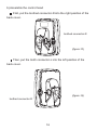
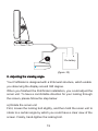
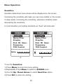
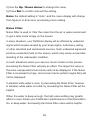
www.goyachting.cn
YTM-10600V2
TM
NAKI 600, 610, 620 Fishfinder
Installation and Operation
Instructions
All right reserved! Except as expressly provided herein, no part of
this manual may be copied, reproduced, republished, transmitted
or distributed for any purpose, without prior written consent of
Yachting Electronic Co., Ltd.
Yachting Electronic may find it necessary to change or end our
policies, regulations, and special offers at any time. We reserve
the right to change or improve its products and to make changes
in the content without obligation to notify any person or
organization.
For current updates or other information, please visit our website:
www.goyachting.cn
Yachting Electronic Co., Ltd
No. 508, Heyan Road, Nanjing, 210038, China
Printed in China
2010 Yachting Electronic Co., Ltd. All rights reserved
i
Introduction
Thank you for choosing our Fish Finder. And welcome to the innovations of Yachting Electronic Co., Ltd! We have been committed to fish
finder R&D activities all the way and its products have been reputed
for their cutting-edge technologies and reliable performance.
Your Fishfinder is a high-quality sonar designed for both professional
and novice fisherman with trouble-free use in a variety of water areas.
We offer one year charge-free maintenance against any damages
induced by non-human factors; and damages happen out-of-warranty
are handled with reasonable charges based on concrete situations.
For details regarding maintenance service, please refer to the
warranty explanations of this User’s Guide.
To familiarize yourself better with the product’s operation and maximize the utilization, we invite you to read the User’s Guide carefully.
Carefully read the installation steps and properly mounting the
transducer and sonar unit which will pay off in optimum performance
of your Fishfinder, and an improper installation, especially the improper
transducer installation may cause your sonar unit working abnormally
or not working at all.
For any possible problems you may encounter during the operation,
please switch to the Trouble Shooting section for reference.
ii
Table of contents
Understand sonar .........................................................................1
No-skipping detection....................................................................2
Dual beam sonar (NAKI610 / 620 only).........................................3
Installation......................................................................................4
Packing list..............................................................................4
Tool List (not included)............................................................5
Transducer installation............................................................5
Transom installation...........................................................5
Shoot-thru-hull transducer installation...............................11
Sonar unit installation..............................................................14
Operation Instruction......................................................................21
Understanding the Fishfinder screen.......................................21
Real time sonar window...........................................................22
Keyboard instruction................................................................23
Menu Operation.............................................................................25
Sensitive..................................................................................25
Noise Filter...............................................................................26
Grayline...................................................................................27
Fish ID. Sens...........................................................................29
Frequency (NAKI610 / 620 only).............................................30
TCG Control.............................................................................31
Chart Speed.............................................................................33
iii
Depth Range............................................................................34
Zoom Range............................................................................36
Backlight..................................................................................37
Contrast...................................................................................38
Overlap Date............................................................................39
Depth Alarm.............................................................................40
Fish Alarm................................................................................41
Battery Alarm...........................................................................41
Beeper.....................................................................................43
Units.........................................................................................43
Language.................................................................................44
System Reset..........................................................................45
Simulator..................................................................................46
Trouble Shooting...........................................................................48
Maintenance.................................................................................50
Guarantee Conditions...................................................................51
Specifications and features...........................................................52
Contact Us....................................................................................54
iv
Understand sonar
If you are familiar with how sonar works, skip ahead to the next
segment. But, if you have never owned sonar Fishfinder before,
this segment will tell you the
basic working theory about
How sonar works
sonar.
Based on the sonar technology,
the Fishfinder could detect the
underwater condition, including
fish, structure, or bottom. After
you finished the installation of
transducer and sonar unit, connect
the sonar unit to the transducer.
The transducer sends a sound
wave signal into the water in a
cone shape. At the source, the
wave is narrow; however as it
penetrates deeper, the sound
wave spreads forming a cone
(think flashlight). The sound wave bounce back to the transducer
when it strikes any object, the object could be fish, structure, bottom
or any other object with density being different from the water.
The transducer amplifies the return signal and sends it back to the
Fishfinder. By measuring the time between the transmission of the
sound wave and when the sound wave bounce back, the Fishfinder
could calculate the distance by the inner microprocessor. Then the
Fishfinder display the information on the screen for you to interpret.
1
No Skipping Detection
Adopted high detecting technique, your fishfinder has a high detecting
distance between
2 sampling points
sonar signals
precision, which enable a “No-skipping detection”.
When sonar works, it continually samples the echo at same interval
(for your fishfinder, it is 0.06mS). And the continuous signals form
different sampling point. The shorter the distance between 2 sampling
points is, the higher precision your fishfinder will be able to detect
minimal object (thinking about the fishing net, the smaller the hole is,
the smaller fish that not being able to leak).
2
Dual beam sonar (NAKI 610 / 620 only)
NAKI 610 / 610 Fishfinder adopts a 200 / 83(50) kHz Dual Beam sonar
system, with which the sonar coverage has a different area of 20°/60°
(12°/ 35°)correspondingly, which enable you get the best bottom information. By the Dual beam sonar setting, you can use the narrow 20°
(12°) beam to penetrate the deep bottom while you are still being able
to use the wide 60°(35°)beam for a wide detection.
R
R
60 20
R
R
12 35
83khz
50khz
200khz
200khz
With the Dual beam sonar system, NAKI610 / 620 provide you an
excellent detecting performance from shallow to very deep water in
both fresh and salt water.
3
Installation
Do not begin the installation unless you have read the manual
instruction carefully, which contains information critical to the correct
installation of your Fishfinder. And for any problems you meet
during the installation, please contact your local dealer for help.
Packing list
Before you install the transducer and sonar unit, please check the
Packing List bellow and make sure you are not missing any items.
A— Sonar unit
B— Bracket
C— Upper twist base
D— Lower twist base
E— Locking bolt
F— Toothed connector-L
G— Toothed connector-R
H— Transducer
I— Pivot
J— Template
K— 3x8mm screws
L— 5x20mm screws
M— Nut
N— 4x15mm screws
O— Pivot bolt
4
Tool List (not included)
Hand drill,
5/32” drill bits,
Phillips and flat-head screwdriver,
Pencil
Marine sealant.
2-part, slow-cure epoxy (for shoot-thru-hull transducer installation)
Transducer Installation
Transom installation
1. Select the mounting location
When you select a mounting location for the transducer, the flowing
should be considered in advance.
The sonar transmission / reception can be affected severely in turbulent
water, so please do not mount transducer behind strakes, rows of rivet,
water intake, discharge port, the immediate area of the propeller(s).
These areas can create turbulence when the boat moves in a high
speed.
2. Mark the location and drill the
mounting holes
a) Make sure the boat is level and no
obvious incline of the shipboardDŽ
b) Hold the template against the
transom of boatˈmark two
mounting holes in the two slots.
The center of two
5
holes should be parallel with water surface. Make sure the distance
between the bottom of template and the lower edge of the transom is
about 0~5mm. distance between the bottom of template and the lower
edge of the transom is about 0~5mm (figure-1).
c) Using a 5/32” bit, drill 2 holes approximate 1” (25mm) deep at the
marked location. Be careful not drilling too deep then 1”.
3. Assemble the transducer
a) Slightly spread the pivot and match the
(figure-2)
transducer to the pivot. The toothed surface
make them not separating easily.
Note: when match the transducer and
pivot, please be careful not assembling
a)
them reversedly. ˄see figure-2ˈa-rightˈ
b-wrong˅
b) Put the locking nut into the slot of pivotˈ
then insert the pivot boltˈhand-tighten
the pivot bolt (figure-3)DŽ
b)
Note˖Do not over tighten the
pivot-bolt with Allen wrenchˈ
locking nut
otherwise you will not being able
to adjust the angle of
pivot
transducerDŽ
pivot bolt
(figure-3)
6
c) Match the pivot to the template (figure-4).
Note: Do not push the pivot into the bracket (see figure-5).
Do not push
the pivot into
the bracket
(figure-4)
(figure-5)
4. Initial installation of transducer
a) Apply marine sealant to the 4 x 15mm screws and the two holes
on transom. Hold the bracket against transom againˈslightly tighten
the template by two 4 x 15mm screws (see figure-6).
Note: Do not over tighten, otherwise you will not being able to
adjust the transducerDŽ
7
b) Adjust the template to make it roughly vertical to the water surfaceˈ
then tighten the two screws with Allen wrench
c) Press the pivot into the bracket, and then rotate the transducer to
make it parallel with the water surface. Note: The pivot match the
transducer by ratchetsˈand the increment is12degree, so in some
situations you may find it impossible to adjust the transducer completely
parallel with the water surface. In this situation a slight incline
(1~5degree) is acceptable.
5. Routing
Routing the cable
You can choose to route the transducer through or over the transom.
If through the transom, please follow the following steps:
a) hold one cable clamp at the position approximate 1/4 distance
rom the top of transom to the transducerˈthen mark the position
with a pencil. Using a 1/8” bit, drill tow holes approximate 3/8”
(10mm) deep.
b) Apply some marine sealant to the hole, and then tighten the
cable clamp with two screws.
c) If more than one cable clamp are needed, repeat step1ˈ2
the template touchs
the transducer
(figure-7)
8
Note
Note˖Make sure the cable between the transducer and the first
clamp is not tighten. otherwise the transducer cable is easily
damaged when adjust the transducer. To avoid this matterˈ
please rotate the transducer to the utmost position before tighten
the first cable clamp (figure-7).
d) When route the transducer cable to the sonar unit, avoid enwinding
the transducer cable with other electrical wires or some electrical
device that may cause interferencel.
6. Test the initial in
installatio
stallation
To get a better installation of the transducer, we suggest you testing
the initial installation and adjust the transducer according to the test
outcome.
Before the test, please make certain you have finished the installation
of the sonar unit and properly connect the transducer cable to the
sonar unit. Also make sure the distance between the transducer and
bottom is not beyond the depth capability of your Fishfinder.
a) Power up the sonar unit and see whether there is sonar information
on display. If yes, it means the sonar unit is properly connected to
the transducer. If notˈplease check the connection between the
sonar unit and the transducer.
b) Firstˈrun your boat at a low speed. See the sonar information on
the screen. If the sonar display comes out normal, then speed up
your boat. Always observe the sonar display during the course. If
signal losing or abnormal sonar display happens when the boat
run at a certain speedˈnote the speed of your boatDŽ
9
c) Adjust the transducer in a small scope and run the boat at the noted
speed (step 2). Then observe the sonar display. If the sonar display is
normal, go to the next step. If not, please adjust the transducer until it
comes out normal. If by any means a normal sonar display can not
be obtained, then it is necessary for you to relocate the position of the
transducer.
7. The final installation
installation
a) Make sure the transducer could be completely immersed into water,
and then adjust the location of template on the transom to make the
transducer immersed into water as low as possible. This will make
the transducer’s transmission / reception being affected by the whirlpool
at the smallest extent when the boat runs at a high speed.
b) As soon as you believe having found
the best mounting location of the
transducer, release the pivot from the
template, then mark the third hold with
a pencil (figure-8).
c) Using a 5/32” bit, drill a hole
appreciated 1” (25mm) deep at the
the third hole
marked position.
(figure-8)
d) Apply some marine sealant in three holes and hold the template
against the transom. After you are certain the installation is completely
in line with the mounting location which you got at step 4, then tighten
the three screws with Allen wrenchDŽ
e) Press the pivot into the template.
10
Shoot-thru-hull installation
Transom installation is the most widely used method. However in
some situation you also could use Shoot-thru-hull transducer installation,
which is more convenient and fast. However, considering of the
material of boat and any possible trapped air bubbles in the material,
sonar signals will be slightly reduced when passing through the boat hull.
1. Preparation
The boat hull should be single layer construction, since the sonar
signal could not pass through air.
Note: The areas being chosen to mount the transducer should be free
from turbulent water. Any ribsǃstrakes and other protrusions that
may create turbulence should be avoided.
inner hull
flotation material
Resin
expoxy
outer hull
With double-hulled boat, you could make the shoot-thru-hull installation
only when some flotation materials (such as plywood, balsa, wood or
foam) are removed from the chosen area. Please see figure-9.
Warning: contact your boat dealers to get the full specifications of
your boat. And never try to remove any materials from the inner hull
before you completely know about the composition of your hull.
11
Chose an appropriate position in the inner hull, then removing the
inner layer of fiberglass and flotation materials, thus the surface of
outer hull exposed.
Epoxy the transducer to the outer layer of fiberglass; press the transducer with a slight twisting motion to purge any trapped air from underneath.
After the epoxy cures for 24hours and be certain that the epoxy is
solidified, fill the remaining space with resin. And then the installation
of transducer is finished.
With the shoot-thru-hull installation, the transducer will not be able to
adjust as soon as it is fixed. So, test before final installation is
necessary.
2. Find a better mounting
mounting location
a) Fill the hull with enough water to submerge the transducer.
b) In the sump of the boat, place the transducer at the identified mounting position, face down. To make the transducer in position,
some heavy object could be used.
c) Turn on the sonar unit, run the boat to water area that the depth is
about 20feet to test whether the sonar display is normal (if needed,
please adjust the sensitivity and depth range). If not, check the
connection between the control head and the transducer.
d) Run the boat at various speed to see the sonar display, if such
phenomena appears: sonar strength obviously decreasing, signal
losing, bottom missing, then note the speed and choose another location
for the transducer, and repeat the step till you get the best mounting location.
12
3. The Permanent Shoot-Thru-Hull installation
a) make sure the surface of the chosen location is clearǃdry and free
of any oil, then sand the mounting surface of transducer with 100
grit sandpaper until it looks very clean and flat.
b) Wipe off the sand debris on mounting surface with a piece of cloth,
and then clean the mounting surface of hull and transducer with
rubbing alcohol.
c) Get a quantity of epoxy and hardener, mix them in a certain proportion and thoroughly, slowly stir them on a paper plate. Avoid
forming air bubbles in the epoxy.
d) When the epoxy looks unworkable (about 20minietes are needed
from the beginning you mixing them), make sure there are no air
bubbles in the epoxy layer, then spread a thin layer of epoxy on
the surface of transducer, a comparably thick layer to the surface
of sand area on the hull.
e) Press the transducer into the epoxy of the sanding area on the hull
with a slight twisting motion, forcing any air bubbles out from underneath. Make sure the face of the transducer will be parallel with
the hull after you finish all the above job.
Warning: do not bump the transducer while the epoxy is wet. It will
take about 24hous for the epoxy curing completely.
Note: weight the transducer with some heavy object to prevent it
from moving during the epoxy curing,
When the epoxy cures completely, drain out the water from the hull.
f) Route the cable to the control head, and now it’s ready to use.
13
Sonar unit installation
1. Find a mounting location
(figure-10)
When you begin the installation of you Fishfinder, the following should
be considered:
a) The location should be convenient for your choosing the best viewing angle.
b) There should be enough room for the sonar unit tilting & twisting
when the installation is finished. For the detailed dimension, please
refer to the figure-9.
c) There should be enough room behind the sonar unit to route the
cable when the installation is finished.
14
d) To get a stable installation, the mounting surface should be flat
enough. Otherwise it will be very hard to fix the lower twist base. And
an instable installation may damage your Fishfinder when the boat
encounters severe wave shock.
2. Installation of the sonar unit
a) Assemble the twist & tilt structure
Hold the bracket to traverse through the upper twist bast
upper twist base
(figure-11)
bracket
Fit the lower twist base to the upper twist base, then fix the
two parts by 4 screws (3x8)
fix by 4 screws
(figure-12)
15
b) Assemble the control head
First, put the toothed connector-R into the right position of the
back cover.
toothed coonector-R
(figure-13)
Then, put the tooth connector-L into the left position of the
back cover
(figure-14)
toothed coonector-R
16
Finally, insert the locking bolt along the side of toothed connecter,
then slightly tighten the locking bolt.
Locking bolt
(figure-15)
c) Fit the twist & tilt structure to the sonar unit
Slot
Protruding strip
(figure-16)
17
Hold the bracket to the back cover, with the protruding strip (on the
bracket) matching the slot (on the bracket). Then press the bracket
into the sonar unit. Finally, properly tighten the locking bolt.
Then you finished the complete assemble, as following:
3. Fix the Fishfinder on the installation surface which you chose
before.
4. Connect the power cable to the boat
Your Fishfinder include a 1.5m long power cable, which is used to
connect to the transducer and battery. Properly connect the power
cable to the transducer and battery, then it is ready to use.
Caution: some boats may have 24 or 36 volt electric system, however
for your Fishfinder, only 12 volt electric system could be adopted.
Any damage from the surplus power will void your warranty.
18
12v battery
(figure-18)
Adjusting the viewin
5. Adjusting
viewing
g angle
Your Fishfinder is designed with a tilt & twist structure, which enable
you observing the display around 360 degree.
When you finished the Fishfinder installation, you could adjust the
sonar unit. To have a comfortable direction for your looking through
the screen, please follow the step below:
a) Rotate the sonar unit
First, loosen the locking bolt slightly, and then hold the sonar unit to
rotate to a certain angle by which you could have a clear view of the
screen. Finally, hand-tighten the locking bolt.
19
locking bolt
hold the bracket to twist
(figure-22)
Note: considering the structure of the sonar unit, the range of adjustable angle is 0~93degree.
b) Twist the bracket
(figure-23)
twist structrue
Hold the bracket, twist it slightly, then you could have any angle in the
range of 0~360 degree.
20
Operation Instruction
Understanding the Fishfinder screen
Water Depth
Water Surface
Water Temp.
Depth range
(Up range)
Voltage Redout
Real Time
Sonar Window
Fish Icon (under
200kHz)
Fish Icon (under
83 or 50kHz)
Bottom shape
Depth range
(Down range)
This chart shows all the information that your Fishfinder display during
the operation. The upcoming sonar information will firstly appears in
the Real Time Sonar window, and then scrolls across the screen from
right to left. So, what you see on the screen (Fish symbols, Fish arches,
bottom shape, etc) is formed by the sonar history.The black line at the
top of the screen represents the water surface, and the water depth,
water temp., as well as real time voltage of battery will appear at the
21
upper left corner as soon as you turn on the sonar unit and the transducer was properly connected.
By moving the transducer slowly at a steady speed, you could see the
bottom shape shown at the bottom of the screen.
Real Time Sonar Window
The plot on the screen demonstrates the sonar history, which varies
at different time segment. So, considering the boat and targets may
continually move when the sonar works, the information displayed on
the screen only shows the time segment when the targets were detected.
To understand the display correctly,
you could imagine dividing the screen
right side
into many parallel “bands” at vertical
direction. Each “band” represents the
signals received by the sonar unit at a
particular time. The closer the position
of “brand” to the right side is, the more
latest signal it represents.
The Real Time Sonar Window shows
the instant time segment when the
instant sonar
returns
targets are detected. With the Real
Time Sonar window, you could
observe the fastest updating which will show you the instant underwater information, including depth, bottom, structure, and fish being
detected.
22
Keyboard instruction
Ent
Exit
The Fishfinder sound a tone when you press the key which means
the unit has accepted a command.
1. POWER & Exit Key
The POWER & Exit key is used to turn the Fishfinder on or off.
It is also used to exit a menu setting.
2. Menu Key
The MENU key is used to enter into a menu setting, and switch
betweens the menus.
3. Ent Key
The Ent key is used to confirm a setting.
4. Up Arrow Key
The Up key is used to select a certain option on a menu.
In some menu option, the Up arrow key is mostly used to increase the value,
23
such as: sensitivity value, noise reject value, depth alarm value, etc.
5. Down Arrow Key
The Down arrow key is used to select a certain option on a menu.
In some menu option, the Down arrow key is mostly used to decrease the
value, such as: sensitivity value, noise reject value, depth alarm value, etc.
24
Menu Operation
Sensitive
Sensitive determines how echoes will be displayed on the screen.
Increasing the sensitivity will make you see more details on the screen.
In deep water, increasing the sensitivity, wheraes in shallow water
decreasing the sensitivity.
In most situation, just setting sensitivity as “Auto” will work well.
SONAR
SONAR
Sensitive
Sensitive
Noise Filter
Graylne
Fish ID. Sens.
Frequency
TCG Control
Noise Filter
Grayline
Fish ID. Sens.
Frequency
TCG Control
Auto.
8
A
B
To set the Sensitive:
1) Press Menu to enter into menu setting.
2) Repeatedly Press Menu to switch to SONAR menu.
3) Use the Up / Down Arrow to select Sensitive option.
4) Press Ent to enter into setting.
25
5) Use the Up / Down Arrow to change the value.
6) Press Ent to confirm and exit the setting.
Note: the default setting is “Auto”, and the menu display will change
from figure A to B as soon as entering menu setting.
Noise Filter
Noise Filter is used to filter the noise from the air or water enviroment
to get a clear sonar image on the screen.
In many situations, your Fishfinder display will be effected by undesired
signal which maybe caused by your boat engine, turbulence, wiring,
or other electrical and mechanical sources. Such undesired signal will
produce unwanted mark on the screen, which may cause a misunderstanding of the underwater condition.
In such situations when you see too much clutter on the screen,
increasing the Noise Filter will play an effect. The larger the value is,
the more unexpected sonar returns will not be displayed. If the Noise
Filter is increased too hige, most sonar returns (which maybe fish) will
not be displayed.
In situation while water is clear, try decreasing the Noise Filter, however
in situation while water is turbid, try increasing the Noise Filter will be
helpful.
When the water is deep enough, the high value setting may greatly
affect or even hinder your Fishfinder’s performance to find the bottom.
So, in deep water, decreasing the Noise Filter value will be helpful.
26
Note: in some situations while you have big trouble with noise,
try finding and fixing the interference source, rather than operating
your Fishfinder with a very high Noise Filter value.
SONAR
Sensitive
Noise Filter
Grayline
Fish ID. Sens.
Frequency
TCG Control
5
To set the Noise Filter:
1) Press Menu to enter into menu setting.
2) Repeatedly Press Menu to switch to SONAR menu.
3) Use the Up / Down Arrow to select Noise Filter option.
4) Press Ent to enter into setting.
5) Use the Up / Down Arrow to change the value.
6) Press Ent to confirm and exit the setting.
Grayline
Grayline is used to let you see both strong and weak signals on the
display.
If Grayline is “on”, weak returns will be shown with dark pixels and strong
27
returns with lighter pixels. This is very helpful of ensuring that
weak signals will be clearly visible on the display;
If Grayline is “off”, strong returns will be shown with dark pixels and weak
returns with lighter pixels. This is very helpful of ensuring that strong
signals will be clearly visible on the display;
SONAR
Sensitive
Noise Filter
Grayline
Fish ID. Sens.
Frequency
TCG Control
Inversed
On
To set the Grayline:
1) Press Menu to enter into menu setting.
2) Repeatedly Press Menuto switch to SONAR menu.
3) Use the Up / Down Arrow to select Grayline option.
4) Press Ent to enter into setting.
5) Use the Up / Down Arrow to select the option.
6) Press Ent to confirm the setting.
7) Press Exit to exit the setting.
28
Fish ID Sens.
Fish ID Sens. is used to adjust the threshold of fish size detection.
If you select a higher setting, then some weaker returns can be detected
and displayed as small fish on screen, which will be very helpful when
you are intending to identify small fish species.
If you select a lower setting, then only strong returns can be detected and
displayed as big fish on screen, which will be very helpful when you are
intending to catch larger fish species.
SONAR
Sensitive
Noise Filter
Grayline
Fish ID. Sens.
Frequency
TCG Control
3
To set the Fish ID Sens.:
1) Press Menu to enter into menu setting.
2) Repeatedly Press Menu to switch to SONAR menu.
3) Use the Up / Down Arrow to select Fish ID Sens. option.
4) Press Ent to enter into setting.
5) Use the Up / Down Arrow to change the value.
6) Press Ent to confirm and exit the setting.
29
Frequency (NAKI 610 / 620 only)
Frequency is used to set which sonar returns will be displayed on the
screen when you use the NAKI610 or NAKI620 dual frequency unit.
a) In 200kHz, the screen and Real Sonar Window will only display
the 200kHz narrow beam sonar returns.
b) In 83 or 50 kHz, the screen and Real Sonar Window will only display
the 83 or 50 kHz narrow beam sonar returns.
a) In 83/200 or 50/200, the screen will display both the 200kHz and
83(50)kHz sonar returns.
Note˖
In single frequency mode, all the detected targets are displayed as
Shaded Fish Symbols. In dual frequency mode, the detected targets
in the 200kHz are displayed as Shaded Fish Symbols, and the
detected targets in the 50 or 83kHz are displayed as Hollow Fish
Symbols as shown below:
Shaded fish symbol
Hollow fish symbol
To set the Frequency:
1) Press Menu to enter into menu setting.
2) Repeatedly Press Menuto switch to SONAR menu.
3) Use the Up / Down Arrow to select Frequency option.
4) Press Ent to enter into setting.
5) Use the Up / Down Arrow to select the option.
30
SONAR
SONAR
Sensitive
Sensitive
Noise Filter
Grayline
Fish ID. Sens.
Noise Filter
Grayline
Frequency
Frequency
TCG Control
TCG Control
Fish ID. Sens.
[ 200KHZ ]
[ 50KHZ ]
[ 50/200KHZ ]
[ 200KHZ ]
[ 83KHZ ]
[ 83/200KHZ ]
(NAKI610)
(NAKI620)
6) Press Ent to confirm the setting.
7) Press Exit to exit the setting.
TCG Control
This function is optimized for high power-output sonar system. It
could help the sonar work properly in a noisy environment.
In order to control the surface noise and self-ring of transducer, the
sensitivity is automatically changed in different depth. The diagram
below shows the sensitivity changes according to depth.
31
sensitivity
....................................
5m depth
0
Note: from the diagram, we can see the TCG function only control
the signal between 0~5 meters. So, if the enviroment is noisy, and
you wish to see the underwater condition in the shallower layer near
0~5m, please set the TCG Control as “On”.
Note: In air, the signal consumption is much bigger than in water. So,
if you try to test the sonar sensitivity in the air, please set theTCG
Control as “Off”.
SONAR
Sensitive
Noise Filter
Grayline
Fish ID. Sens.
Frequency
TCG Control
Off
On
32
To set the TCG Control:
1) Press Menu to enter into menu setting.
2) Repeatedly Press Menuto switch to SONAR menu.
3) Use the Up / Down Arrow to select TCG Control option.
4) Press Ent to enter into setting.
5) Use the Up / Down Arrow to select the option.
6) Press Ent to confirm the setting.
7) Press Exit to exit the setting.
Chart Speed
Chart Speed control how fast the sonar information moves across
the screen.
With the high speed, you could see more information across the screen;
however the fast moving information makes you feel difficult to interpret
the fish details and bottom.
With the low speed, you feel easeful to have enough time to interpret
the fish details and bottom. However the compressed information
may cause a little problem for you to interpret them.
To achieve better images, try adjusting the Chart Speed level to
match how fast you are moving in the actual condition: stationary,
drifting slowly or running you boat at different speed.
33
DISPLAY
Chart Speed
Depth Range
Zoom Range
Backlight
Contrast
Overlap Data
10
To set the Chart Speed:
1) Press Menu to enter into menu setting.
2) Repeatedly Press Menu to switch to DISPLAY menu.
3) Use the Up / Down Arrow to select Chart Speed option.
4) Press Ent to enter into setting.
5) Use the Up / Down Arrow to change the value.
6) Press Ent to confirm and exit the setting.
Depth Range
Depth Range determine in which portion the bottom will display in
the screen.
For example, if the actual depth is 10m, and the current Depth Range
is 0~ 20m, then the bottom will display on 50% position from the top
screen. Also if the Depth Range is 0~40, then he bottom will display
on 25% position from the top screen. and so on).
34
There are total 9 levels for the depth range setting:
a) with feet unit: 15, 30, 60, 120, 180, 240, 480, 720, Auto
b) with meter unit: 5, 10, 20, 40, 60, 80, 150, 220, Auto
The default setting is “Auto”, which will keep the bottom always display
in a proper position on the screen. However in some certain situation,
you could also manually select a depth range.
DISPLAY
DISPLAY
Chart Speed
Chart Speed
Depth Range
Depth Range
Zoom Range
Zoom Range
Backlight
Backlight
Contrast
Contrast
Overlap Data
Overlap Data
Auto.
220
A
B
To set the Depth Range:
1) Press Menu to enter into menu setting.
2) Repeatedly Press Menu to switch to Display menu.
3) Use the Up / Down Arrow to select Depth Range option.
4) Press Ent to enter into setting.
5) Use the Up / Down Arrow to change the value.
6) Press Ent to confirm and exit the setting.
35
Note: after you enter into the setting by press Ent key, the operation
figure will change from A to B, then just press Down Arrow key to
change the levels.
Zoom Range
Zoom Range is used to enlarge some certain depth segment, which is
helpful for you to see small details, fish signals and bottom structure.
Your fishfinder has a wonderful performance to see any depth segment
with any scale.
For example, if the current Depth Range is 0~40m, by setting Zoom
Range to 20~25m, you can see the sonar image of the 20~25m depth
segment with a 8x scale. And by setting it to 20~30m, you can see
the sonar image of the 20~30m depth segment with a 4x scale.
DISPLAY
Chart Speed
Depth Range
Zoom Range
Backlight
Contrast
Overlap Data
Disabled
On
Up:
0m
Low: 60m
36
To set the Zoom Range:
1) Press Menu to enter into menu setting.
2) Repeatedly Press Menu to switch to DISPLAY menu.
3) Use the Up / Down Arrow to select Zoom Range Option.
4) Press Ent to enter into setting.
5) Use the Up / Down Arrow to select the option.
6) Press Ent to confirm the setting.
7) Press Exit to exit the setting.
Note: after select “on” option:
1) press Ent to switch to the “Up” or “Low” Range.
2) Press Up / Down Arrow to change the value.
3) Press Ent to confirm the setting.
4) Press Exit to exit the setting.
Backlight
The backlight allow the unit to be used at night.
DISPLAY
Chart Speed
Depth Range
Zoom Range
Backlight
Contrast
Overlap Data
10
37
There are 10 levels for you to adjust the brightness of backlight.
To set the Backlight:
1) Press Menu to enter into menu setting.
2) Repeatedly Press Menu to switch to DISPLAY menu.
3) Use the Up / Down Arrow to select Backlight option.
4) Press Ent to enter into setting.
5) Use the Up / Down Arrow to change the value.
6) Press Ent to confirm and exit the setting.
Contrast
Contrast can let you to get a suitable display when you operate the
unit.
DISPLAY
Chart Speed
Depth Range
Zoom Range
Backlight
Contrast
Overlap Data
10
To set the Contrast:
1) Press Menu to enter into menu setting.
2) Repeatedly Press Menu to switch to DISPLAY menu.
3) Use the Up / Down Arrow to select Contrast option.
38
4) Press Ent to enter into setting.
5) Use the Up / Down Arrow to change the value.
6) Press Ent to confirm and exit the setting.
Overlap Data
On the upper left coner display, there are 3 readout: Water depth,
Temperature, Voltage. Overlap Data determin which readout will be
displayed.
DISPLAY
Chart Speed
Depth Range
Zoom Range
Backlight
Contrast
Overlap Data
Depth
Temperature
Voltage
To set Overlap Data:
1) Press Menu to enter into menu setting.
2) Repeatedly Press Menu to switch to DISPLAY menu.
3) Use the Up / Down Arrow to select Overlap Data option.
4) Press Ent to enter into setting.
5) Use the Up / Down Arrow to select the option.
6) Press Ent to confirm the option being displayed or not.
7) Press Exit to exit the setting.
39
Depth Alarm
The Fishfinder sound an alarm tone when the bottom goes shallower
or equal than the alarm’s setting.
Note: once triggered, an alarm message will appear on the screen.
You can press Menu key to exit the
depth alarm mode, however the alarm
Shallow Alarm !
will trigger again until your boat
move to an area where the water depth is beyond the depth alarm
range.
You also can choose exitting alarm mode by enter into Depth Alarm
menu and artificially increase the current depth alarm value to a safe
grade.
ALARM
Depth Alarm
Fish Alarm
Battery Alarm
1m
To set the Depth Alarm:
1) Press Menu to enter into menu setting.
2) Repeatedly Press Menu to switch to ALARM menu.
3) Use the Up / Down Arrow to select Depth Alarm option.
4) Press Ent to enter into setting.
40
5) Use the Up / Down Arrow to change the value.
6) Press Ent to confirm and exit the setting.
Fish Alarm
Fish Alarm is used to set whether the Fishfinder sounds an alarm tone
when it detects what it determines to be a fish.
ALARM
Depth Alarm
Fish Alarm
Battery Alarm
Off
On
To set the Fish Alarm:
1) Press Menu to enter into menu setting.
2) Repeatedly Press Menuto switch to Alarm menu.
3) Use the Up / Down Arrow to select Fish Alarm option.
4) Press Ent to enter into setting.
5) Use the Up / Down Arrow to select the option.
6) Press Ent to confirm the setting.
7) Press Exit to exit the setting.
Battery Alarm
The Fishfinder sounds an alarm tone when the battery strenth is lower
then the setting.
41
ALARM
Depth Alarm
Fish Alarm
Battery Alarm
10.0v
To set the Battery Alarm:
1) Press Menu to enter into menu setting.
2) Repeatedly Press Menu to switch to ALARM menu.
3) Use the Up / Down Arrow to select Battery Alarm option.
4) Press Ent to enter into setting.
5) Use the Up / Down Arrow to change the value.
6) Press Ent to confirm and exit the setting.
Note: once triggered, an alarm message
will appear on the screen. You can press
Voltage Low !
any key 2 times to clear the alarm message.
However the alarm will repeatedly apprear unless the voltage of the
battery is higher then the Battery Alarm setting.
You can manually choose exitting the Battery Alarm Mode by entering
into Battery Alarm menu setting, and just changing the setting to a
safe value will be ok.
42
Beeper
Beeper is used to determine whether the fishfinder will sound a tone
when a key is pressed.
SYSTEM
Beeper
Units
Language
System Reset
Simulator
Off
On
To set the Beeper
1) Press Menu to enter into menu setting.
2) Repeatedly Press Menu to switch to SYSTEM menu.
3) Use the Up / Down Arrow to select Beeper option.
4) Press Ent to enter into setting.
5) Use the Up / Down Arrow to select the option.
6) Press Ent to confirm the setting.
7) Press Exit to exit the setting.
Units
Units is used to choose the depth unit and temp. unit.
To set the units:
1) Press Menu to enter into menu setting.
2) Repeatedly Press Menu to switch to Units menu.
43
SYSTEM
Beeper
Units
Language
System Reset
Simulator
Feet / °C
Feet / °F
Meter / °C
Meter / °F
3) Use the Up / Down Arrow to select Units option.
4) Press Ent to enter into setting.
5) Use the Up / Down Arrow to select the option.
6) Press Ent to confirm the setting.
7) Press Exit to exit the setting.
Language
Language is used to choose the language of menu operation.
To set the Language:
1) Press Menu to enter into menu setting.
2) Repeatedly Press Menu to switch to SYSTEM menu.
3) Use the Up / Down Arrow to select Language option.
4) Press Ent to enter into setting.
5) Use the Up / Down Arrow to select the option.
6) Press Ent to confirm the setting.
44
SYSTEM
Beeper
Units
Language
System Reset
Simulator
Deutsch
English
Français
Italiano
7) Press Exit to exit the setting.
System Reset
System Reset is used to restore original factory setting.
SYSTEM
Beeper
Units
Language
System Reset
Simulator
No
Yes
To set the System Reset:
1) Press Menu to enter into menu setting.
2) Repeatedly Press Menu to switch to SYSTEM menu.
45
3) Use the Up / Down Arrow to select System Reset option.
4) Press Ent to enter into setting.
5) Use the Up / Down Arrow to select the option.
6) Press Ent to confirm the setting.
7) Press Exit to exit the setting.
Simulator
Simulator is used to let you practicing using the Fishfinder as if
you were on the water.
Under the simulating mode, the simulated bottom signal with fish
signals will display and move across the screen, and under the
simulating mode, you still could change settings to view different
sonar image to have a complete understanding of your Fishfinder.
SYSTEM
Beeper
Units
Language
System Reset
Simulator
Off
On
To run the Simulator:
1) Press MENU to enter into menu setting.
2) Repeatedly Press Menu to switch to SYSTEM menu.
46
3) Use the Up / Down Arrow to select Simulator option.
4) Press Ent to enter into setting.
5) Use the Up / Down Arrow to select the “On”option.
6) Press Ent to confirm the setting.
7) Press Exit to exit the setting.
To exit simulator, just enter into the Simulator setting and change
the option to “Off”
47
Trouble shooting
Unit doesn’t power up.
a. Check the cable connection and wiring. Make sure the cable is
properly connected to the Fishfinder. The red wire connects to
positive terminal, and black to negative terminal or ground.
b. Make certain the battery voltage is not lower then the warnning
value (10v).
c. Check the fuse.
Weak Bottom Echo, Unstable Depth Reading, or No Fish Signals.
a) Make certain the transducer is installed properly.
b) Extremely heavy vegetation may confuse the sonar signal, causing
it to misinterpret the depth. If you are certain that the readings are
incorrect under these conditions, discontinue use.
c) Oil, dirt and fuel might cause a film to form on the transducer and
reduce its effectiveness. Cleaning the face of the sensor might help.
d) Electrical noise from the boat's motor can interferes with the sonar,
which will cause some weaker signals being eliminated.
e) Please check the battery voltage. The unit's transmitter power will
decrease due to the voltage drop. And this will reduce its ability to
find the bottom or targets.
f) The sonar might be in turbulent water. Mounting it in a smooth flow
of water might help.
No depth readout when transducer is installed in the
way “Shoot-thru-hull”.
Make certain the hull of the boat is single layer construction. Also any
air trapped in the lamination of the fiberglass would prevent the sonar
48
signal passing through, which will cause no depth readout.
Bottom disappears, suddenly weakens, when the boat
moves at high speed
a) The sonar might be in turbulent water. See the installation guide
and adjust the transducer position to a smooth flow of water.
b) Electrical noise from the boat's motor can interferes with the sonar,
which will cause some weaker signals being eliminated. Try increasing the Noise Reject level or routing Fishfinder”s power and the
transducer cable away from the electrical source.
Nothing appears on the display even you can see fish
under the transducer.
a) Check the transducer installation to make certain it is properly
installed. An improper installation may cause sonar signal lost.
b) Oil, dirt and fuel might cause a film to form on the transducer and
reduce its effectiveness. Cleaning the surface of the transducer
might help.
c) Electrical noise from the boat's motor can interferes with the sonar,
which will cause some weaker signals being eliminated.
The display become so cluttered that you even could not
achieve a clear bottom
Such cluttered display maybe caused because:
a) the water is too low
b) the water is too turbid
c) there are so much debris in the water,
Increasing the Noise Reject to 8 or a bigger value will be helpful.
49
Maintenance
With a view to making most of your Fishfinder, we recommend you
follow the steps bellow and carry out maintenance.
a) For the case
Cleaning the sonar unit’s outer case (except for the screen) with a
cloth dipped mild detergent solution, and then wipe it dry.
b) For the screen
Use a piece of soft cloth or pelt to clean the screen (fresh water or
eyeglass cleaner can be used if needed). Stubborn dirt or oil stains
remaining on the screen shall not be wiped with force; otherwise it
may scratch the surface. Additionally, give daily attention to ensure
the screen is keep of any chemicals.
Storage
Never place your Fishfinder in an enclosed compartment of the vehicle!
High temperature building up due to concentrated air in hot days can
pose damage to internal electronic parts.
50
Guarantee Conditions
a) We assure you this product is free from defects in materials and
workmanship. The warranty coverage is One Year from the date
of purchase, during which if the unit fails to perform as described
in the product’s written specifications, we will repair or replace it
free of charge. As for products exceeding the warranty coverage,
the maintenance department will charge customers some fees
according to the real situation.
b) This warranty is void if damage or malfunction is due to abuse, misuse,
accident, failure to reasonably maintain, improper installation or
use, or unauthorized alteration or repairs. Our company retains
the final right to judge or repair the defected products.
c) Our company holds the right to update the products. And it is not
obligated for our company to update the former products according
to the new standard.
51
Specifications and features
Specifications:
Display: ............................................4.5”(115mm), FSTN LCD
Backlighting
Resolution: .......................................240 pixel x 128 pixel resolution
4-level grayscale
Depth Capability................................NAKI 600: 700 feet (230 m)
NAKI 610: 850 feet (280 m)
NAKI 620: 1150 feet (350 m)
Operating frequency………....………200 kHz for NAKI600
200 / 83kHz for NAKI610
200 / 50KHZ for NAKI 620
o
Sonar coverage………....……………NAKI600: 20 Cone Angle
o
o
o
o
NAKI610: 20 / 60 Cone Angles
NAKI620: 12 / 35 Cone Angle
Power Requirment............................10~18 volts DC
Power Output…........................….... NAKI600: 1200 watts peak-topeak/ 150 watts (RMS),
NAKI610: 1600 watts peak-topeak/ 200 watts (RMS),
NAKI620: 1800 watts peak-topeak/ 225 watts (RMS),
o
o
Operational Temperature……......…-10 C to 50 C (14 F to122 F)
Case Size……......................…....... 7.5" x 4.2" x 1.9" (190 x 107 x 98
mm) Suitable for saltwater use
Transducer Cable Length................ 20ft (6m)
52
Features
Real time sonar windows .
Fresh / Salt Water Environment .
Displays fish targets at higher boat speeds .
Friendly and convenient menu operation.
IPX7 waterproof casing design.
Tilt & twist quick release mount .
Full one-year warranty, extended wattanties available
53
Contact Us
Contact Our Resource Center in any of
the following days:
By telephone:
Monday - Friday: 8.am. to 5:30 pm.
(Central Standard Time)
0086 25 84680809
Or by e-mail:
Typically we respond to you in 2 business days
[email protected]
For direct shipping, our address is:
No.508, Heyan Road,
Nanjing, 210038, China
Yachting Electronic Co., Ltd
54
www.goyachting.cn