1
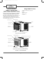
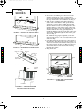
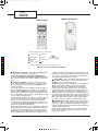
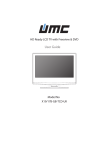
P1_Owners Guide - 5K,6K, 8K.pdf
30/01/2008
1:06:42 PM
CA_
SERIES
OWNER’S GUIDE
For future reference, fill in the information below and
keep this guide in a safe place. Please keep a copy of
your receipt for warranty purposes.
This book is for CA0516K mechanical control air
conditioners and CA0616KR and CA0816KR
electronic control room air conditioners.
DEALER NAME ___________________________________________________
ADDRESS ________________________________________________________
TELEPHONE _____________________________________________________
MODEL/CATALOG NUMBER _______________________________________
SERVICE DISCRETE NUMBER _____________________________________
SERIAL NUMBER _________________________________________________
PLEASE KEEP A COPY OF YOUR RECEIPT FOR WARRANTY PURPOSES.
CONTENTS
Page
A FEW WORDS ABOUT YOUR NEW
AIR CONDITIONING UNIT . . . . . . . . . . . . . . . . . . . . . .2
REQUIRED TOOLS. . . . . . . . . . . . . . . . . . . . . . . . . . . . . . . . . .2
INSTALLATION . . . . . . . . . . . . . . . . . . . . . . . . . . . . . . . . . . . 3-7
POWER CORD. . . . . . . . . . . . . . . . . . . . . . . . . . . . . . . . . . . . . .3
WIRING & LOCATION . . . . . . . . . . . . . . . . . . . . . . . .4
WINDOW INSTALLATION . . . . . . . . . . . . . . . . . . . . . . . .5
STORM WINDOW APPLICATIONS . . . . . . . . . . . . . . . .7
OPERATION . . . . . . . . . . . . . . . . . . . . . . . . . . . . . . . . . . . . . . 7 -9
MECHANICAL CONTROLS . . . . . . . . . . . . . . . . . . . . . . .7
ELECTRONIC CONTROLS. . . . . . . . . . . . . . . . . . . . . . . . .7
ENERGY SAVING TIPS . . . . . . . . . . . . . . . . . . . . . . . . . . . .9
Page
MAINTENANCE . . . . . . . . . . . . . . . . . . . . . . . . . . . . . . . . . . . . 9
CLEAN FILTER . . . . . . . . . . . . . . . . . . . . . . . . . . . . . . . . . . . 9
CLEAN FRONT PANEL . . . . . . . . . . . . . . . . . . . . . . . . . . . 9
CLEAN BASEPAN . . . . . . . . . . . . . . . . . . . . . . . . . . . . . . . . 9
CARE OF THE REMOTE CONTROL . . . . . . . . . . . . . . . 9
REMOTE CONTROL BATTERY
REPLACEMENT . . . . . . . . . . . . . . . . . . . . . . . . . . . . . . . . 9
TROUBLESHOOTING . . . . . . . . . . . . . . . . . . . . . . . . . . . 10-12
Part Number 421 02 9100 00 - Printed 02/08
P2_Owners Guide - 5K,6K, 8K.pdf
30/01/2008
8:38:31 PM
CA_
SERIES
A FEW WORDS
ABOUT YOUR NEW
AIR CONDITIONING UNIT
REQUIRED TOOLS
•
•
•
•
•
•
•
Thank you for choosing a Climette room air conditioner
to cool your home or office. In addition to providing
economical cooling comfort, Climette room air conditioners filter and dehumidify the air in the room.
This owner’s guide will supply all the information you
need to install, operate, and maintain your new air
conditioning unit. Please read the entire manual
before installing the unit. See Fig. 1 for a part identification and description of the unit.
Phillips and flathead screwdrivers
pencil
level
measuring tape
drill
1/ -in. drill bit
8
scissors
HORIZONTAL AIR VANE
INTERIOR AIR OUTLET
VERTICAL AIR VANE
CABINET
AIR FILTER (INSIDE)
FRONT PANEL
EXTERIOR
AIR INLET
INTERIOR AIR
INLET GRILLE
CONTROL KNOBS
POWER CORD
CA0516K (MECHANICAL CONTROL)
HORIZONTAL AIR VANE
INTERIOR AIR OUTLET
VERTICAL AIR VANE
EXHAUST AIR LEVER (FOR CA0816KR ONLY)
CABINET
AIR FILTER (INSIDE)
FRONT PANEL
EXTERIOR
AIR INLET
INTERIOR AIR
F
HR
INLET GRILLE
TIM ER
FAN
SPEED
M O DE ON
/OFF
Airc ond it
ione r
REMOTE CONTROLLER
CONTROL PANEL
POWER CORD
CA0616KR AND CA0816KR (ELECTRONIC CONTROL)
FIGURE 1 — AIR CONDITIONER
2
P3_Owners Guide - 5K,6K, 8K.pdf
30/01/2008
8:41:56 PM
INSTALLATION
• The portable air conditioner should be connected
to a 115 V, 60 Hz, 15- or 20-amp fused 3-prong
grounded outlet .
Power Supply Cord
NOTE: Your unit’s device may differ from the one shown.
• The use of a time-delay fuse or time-delay circuit
breaker is recommended.
• All wiring must comply with local and national
electrical codes and be installed by a qualified
electrician. If you have any questions, contact
a qualified electrician.
Electrical Requirements
A Reset Button
B Test Button
This room air conditioner is equipped with a power supply cord required
by UL. This power supply cord contains state-of-the-art electronics that
sense leakage current. If the cord is crushed, the electronics detect leakage
current and power will be disconnected in a fraction of a second.
Totest your power supply cord:
1.
2.
3.
4.
ELECTRIC SHOCK HAZARD
Plug power supply cord into a grounded 3-prong outlet.
Press RESET.
Press TEST (listen for click; Reset button will trip and pop out).
Press and release RESET (listen for click; Reset button will latch
and remain in).The power supply cord is ready for operation.
NOTES:
• The Reset button must be pushed in for proper operation.
• The power supply cord must be replaced if it fails to trip when the
• Plug into a grounded 3-prong outlet.
• Do not remove ground prong.
test button is pressed or fails to rest.
• Do not use an adapter.
• Do not use an extension cord.
• Failure to follow these instructions can
result in death, fire, or electrical shock.
•
Do not use the power supply cord as as an off/on switch. The
power supply cord is designed as a protective device.
•
A damaged power supply cord must be replaced with a new power
supply cord obtained from the product manufacturer and must not
berepaired.
• The power supply cord contains no use serviceable parts. Opening
the tamper-resistant case voids all warranty and performance claims.
INSTALLATION INSTRUCTIONS
Unpack the Air Conditioner
Remove packaging materials
• Remove and properly dispose of packaging materials.
Remove tape and glue residue from surfaces before
turning on the air conditioner. Rub a small amount
of liquid dish soap over the adhesive with your fingers.
Wipe with warm water and dry.
EXCESSIVE WEIGHT HAZARD
• Do not use sharp instruments, rubbing alcohol,
flammable fluids, or abrasive cleaners to remove
tape or glue. These products can damage the
surface of your air conditioner.
Use two or more people to move and
install air conditioner.
Failure to do so can result in back or
other injury.
• Handle air conditioner with care.
3
P4_Owners Guide - 5K,6K, 8K.pdf
30/01/2008
1:01:48 PM
CA_
SERIES
WIRING&LOCATION
Make sure the window and frame are structurally
sound and free from dry or rotted wood. Replace wood
if necessary or relocate to different window.
For maximum efficiency, install the air conditioner on
the side of the house or building that has more shade
than sunlight.
Provide sufficient clearance for the air conditioner to
allow proper air circulation through and around the
unit. The rear of the unit must be outdoors (not in a
garage or inside of the building). Provide 20-in. of
clearance on each side of the unit. Provide 20-in. of
clearance from the rear of the unit to any obstruction.
Provide 12-in. of clearance from the top of the unit. See
Fig. 2.
Unit should be at least 30-in. above the floor and outside ground.
Curtains and other objects should be moved if they
block indoor airflow.
Unit must be within reach of a proper electrical wall
outlet. Do not use an extension cord.
The unit was designed to evaporate condensation
under normal conditions. Under extreme humidity
conditions, excess condensation may cause the
basepan to overflow to the outside of the unit. The unit
should be installed where condensation drip cannot
cause damage.
Your Climette room air conditioner was designed to be
installed in a single or double hung window. This air
conditioner is not designed for use with vertical (slider
type) windows.
Electrical shock can cause injury or death. Do not
install unit or remove front grille with the power
cord plugged in. Be sure unit is unplugged before
performing any installation or maintenance.
WIRING
C
M
Y
CM
MY
CY
The air conditioner is powered by plugging it into a
compatible wall outlet. The electrical outlet MUST
match the plug on the unit power cord. See Table 1 for
receptacle types and fuses. The unit nameplate contains unit electrical data, unit ratings, and identification numbers. The unit nameplate is located on the
right side of the unit. Do not use a plug adapter or an
extension cord.
Check available power supply and resolve any wiring
problems before installing and operating the air conditioner. If wiring is required, all wiring must comply
with all local and national electrical codes. All wiring
must be installed by a qualified electrician. If you have
any questions regarding the unit electrical data or wiring, consult a qualified electrician before installation.
For your safety, this air conditioner is grounded
through the power cord plug when plugged into a
matching wall outlet. The power cord is 60-in. long.
AWNING
20"
MIN.
CMY
K
TABLE 1 — RECEPTACLE TYPE AND FUSES
12" MIN.
RECEPTACLE TYPE AND FUSES
VOLTS INDICATED/Hz
125/60
AMPS
15
WALL OUTLET
20"
MIN.
FUSE SIZE
TIME DELAY FUSE
(Circuit Breaker)
15
Plug Type
SIDE
OBSTRUCTION
30" MIN.
FENCE,
WALL, OR
OTHER
OBSTACLE
LOCATION
GROUND
The room air conditioner is designed to fit easily into a
single or double hung window. However, since window
designs vary, it may be necessary to make some modifications for safe and proper installation.
FIGURE 2 — AIR CONDITIONER CLEARANCES
4
P5_Owners Guide - 5K,6K, 8K.pdf
30/01/2008
1:06:06 PM
WINDOW INSTALLATION
To install the room air conditioner in a window, perform the following procedure.
1. Check contents of installation hardware package
provided with air conditioner. See Table 2. Make
sure all the items are provided.
6.
TABLE 2 —INSTALLATION HARDWARE PACKAGE
ITEM
7.
QTY
3/
4-in.
Screws
12
3/
8-in.
Screws
8
L-Bracket
2
8.
Side Bracket
2
Seal
1
Foam
1
Right and Left
Side Shutters
1
9.
2. Determine which window will be used for installation. See Location section on this page.
3. Check that the window opening dimensions are
suitable for installation. For CA0516K and
CA0616KR units, the window must be from 21 to
35-in. wide and the window must open at least
13-in. high. For CA0816KR units,the window must
be from 22 to 36-in. wide and the window must
open at least 14-in. high. It is recommended that
the window sill be at least 5/8-in. thick to support
the weight of the air conditioner. See Table 3 for
unit dimensions.
TOP CHANNEL
TABLE 3 —AIR CONDITIONER CABINET
DIMENSIONS
UNIT
CA0516K,
CA0616KR
CA0816KR
WIDTH (in.)
LENGTH (in.)
HEIGHT (in.)
17.7
15.7
12.4
18.5
17.7
13.7
top and bottom channels on the cabinet. Attach
the shutters to the cabinet using four 3/8-in.
screws (provided). See Fig. 3.
A piece of thin foam sealing is provided. Cut piece
to fit across the bottom of the window sash. See
Fig. 4. After the foam seal has been cut, remove
the peel-off backing and stick to bottom of
window.
Measure the width of the inside sill of the window
and mark the center of the sill. See Fig. 5. Measure 7 1/2-in. from the center on both sides and
mark on window sill. Mount the two L-brackets on
the window sill with a 3/4-in. screw (provided). See
Fig. 6. The L-brackets will hold the bottom channel of the air conditioner cabinet in the correct
position when installed. Check that brackets are
in the correct position before installing.
Place air conditioner in the window. The bottom
channel of the air conditioner should be between
the window sill and the L-brackets. Lower the
window sash until it rests firmly behind the upper
channel. Make sure the top and bottom of the cabinet fits snugly to the window opening. See Fig. 7.
Secure the air conditioner to the window sill. See
Fig. 8. Remove the 3/8-in. screw from the bottom of
each side of the air conditioner. Install side brackets (provided) on each side of the air conditioner
using the screws that were just removed. Leave
screws loose. Mount side brackets onto the window sill next to the air conditioner using two
3/4-in. screws (provided) for each bracket. Tighten
3/8-in. screws to secure brackets to air conditioner.
SIDE SHUTTER
INSTALLATION
SCREWS
4. For storm windows, open or remove the outer
storm window before installing the air conditioner.
Remove any screens that are in the window.
5. Install the side shutters (provided). The side shutters are identified as right and left on each frame.
Slide the top and bottom shutter frames into the
BOTTOM
CHANNEL
FIGURE 3 — SIDE SHUTTER INSTALLATION
5
P6_Owners Guide - 5K,6K, 8K.pdf
30/01/2008
1:01:31 PM
CA_
SERIES
10. Secure the air conditioner to the bottom of the
window sash with one 3/4-in. screw provided.
Screw is installed through the hole in the center of
the top channel of the air conditioner. See Fig. 8.
11. Pull out the expanding side shutters from the
sides of the air conditioner. The panels should
expand to cover the entire width of the window.
There is a hole provided in the top end of each side
shutter which is used to secure the panels to the
window. There is a tab on the bottom of the side
shutter provided to secure the side shutter to the
window sill. With the wing panels expanded,
mark the drilling locations on the sides of the window frame and sill (through the holes in the panels). See Fig. 8.
12. Drill the holes marked in Step 11 with 1/8-in. drill
bit. With the wing panels expanded, secure the
wing panels with two 3/4-in. screws provided (each
side). See Fig. 8.
13. Cut thick foam seal (provided) to fit the length of
the window. Insert the foam seal between the top
of the lower window sash and the window panes of
the upper window. See Fig. 8. Make sure there is
a firm fit to prevent air leakage between the windows. This also prevents insects from entering
through the window.
14. Plug in the unit.
SEAL
FIGURE 4 — FOAM SEAL INSTALLATION
CENTER LINE
C
FIGURE 5 — DETERMINE CENTER OF SILL
M
Y
OUTER SILL
3/4"
SCREW
INNER SILL
CENTER LINE
CM
3/4"
SCREW
MY
CY
CMY
BRACKET
SHORT SIDE
7.5
FOAM
7.5
K
FIGURE 6 — L-BRACKET INSTALLATION
3/4" SCREW
3/4" SCREW
3/4"
SCREW
SEAL
3/8" SCREW
3/4" SCREW
FIGURE 8 — SECURE AIR CONDITIONER
TO WINDOW
L BRACKET
FIGURE 7 — AIR CONDITIONER
INSTALLATION LOCATION
6
P7_Owners Guide - 5K,6K, 8K.pdf
30/01/2008
1:05:49 PM
STORM WINDOW APPLICATIONS
a thermostat dial to set desired room temperature. See
Fig. 10.
The electronic control consists of a control panel and a
remote control. Both the control panel or the remote
control can be used to set cooling and fan modes and
adjust the desired temperature. See Fig. 11. Other
additional features are provided.
If the window is blocked by a storm window frame and
the storm window frame cannot be removed, a mounting board (field provided) will need to be added to the
window sill. The air conditioner needs to be pitched
downward to the back in order for condensate to drain
properly. The frame of the storm window (or any other
obstruction) must be at least 3/4-in. lower than the
window sill. If the storm window frame is not at least
3/ -in. below the window sill, then a mounting board
4
will need to be added to raise the height of the window
sill. See Fig. 9. The board will need to be provided and
cut by the installer.
1. The wood mounting board should be a minimum
of 1 1/2-in. wide and should run the length of the
window. The thickness of the mounting board is
dependent on the height of the storm window
frame. The mounting board should raise the front
of the air conditioner high enough so that the unit
will be pitched downward at least 5/8-in. when the
back of the unit is resting on the storm window
frame. See Fig. 9.
2. Cut the wood mounting board to fit the window.
3. Install the wood mounting board on the window
using 2 field-provided nails or screws.
4. Drain holes or slots in storm window frame must
not be caulked or painted shut. Holes are needed
to drain rain water and condensate. Ensure that
trapped water can drain out.
MECHANICAL CONTROLS
TURN UNIT OFF — To turn the unit OFF, set the
dial to the OFF position. The air conditioner will not
operate when the dial is set to OFF.
COOLING MODES — The air conditioner can be
set to two different cooling modes — LOW COOL or
HIGH COOL. HIGH COOL mode is recommended for
very warm days or when a fast initial cooling of the
room is desired. LOW COOL mode is recommended on
slightly warm days or after the room temperature has
reached its desired setting.
NOTE: After setting a mode, allow 3 minutes to pass
before changing modes.
FAN MODE —The air conditioner can be set to
LOW FAN or HIGH FAN mode. In FAN mode, the fan
operates to circulate the air in the room, but there is
no cooling operation. This mode is used to keep the
room air circulating when cooling is not needed. The
fan can be set to HIGH FAN for maximum air circulation without cooling or LOW FAN for moderate air circulation without cooling.
THERMOSTAT — The thermostat dial is numbered
from 1 to 9. The lowest (least cooling) setting is 1. The
highest (most cooling) setting is 9. Turn the thermostat dial clockwise to lower the room temperature.
Turn the dial counterclockwise to raise the room
temperature.
ELECTRONIC CONTROLS
Either the remote control or the control panel on the
air conditioner can be used. The battery of the remote
control will need to be installed before it can be used.
MODE
FIGURE 9 — STORM WINDOW APPLICATIONS
THERMOSTAT
KNOB
OPERATION
The mechanical-type controlis used on your CA0516K
Climette air conditioner. The electronic-type control is
used on your CA0616KR and CA0816KR Climette air
conditioner. Refer to the correct section for your air
conditioner.
The mechanical controls consist of a dial which can be
set to different modes of cooling and fan operation and
MODE KNOB
THERMOSTAT
FIGURE 10 — MECHANICAL CONTROLS
7
P8_Owners Guide - 5K,6K, 8K.pdf
30/01/2008
1:01:12 PM
CA_
SERIE
REMOTE CONTROLLER
CONTROL PANEL
F
HR
Power
Timer
Mode
Power Saver
Auto
Fan Speed
High
Mid
Low
_
+
Temp/Time
FAN
SPEED
TIMER
MODE
ON/ OFF
Airconditioner
Indication symbols of LED on control panel:
C
M
Y
AUTO FAN SPEED
COOLING
LOW FAN SPEED
FAN ONLY
MEDIUM FAN
SPEED
ENERGY-SAVING
HIGH FAN SPEED
TIMER
F
HR
DISPLAY SET TEMP
DISPLAY SET TIMER
CM
ABOVE LED LIGHTS ON WHEN THE RELEVANT MODE IS IN USED.
MY
FIGURE 11 — ELECTRONIC CONTROLS
CY
CMY
K
TURN UNIT OFF/ON — Press the ON/OFF button
on the remote control or control panel.
NOTE: To switch from Celsius to Fahrenheit,
press the UP ARROW and DOWN ARROW buttons on
the control panel (not the remote control) at the same
time.
conditioner will run in Cooling mode. When the room
temperature is lower than 66 F, the unit will turn off
(no cooling or fan). At all other times, cooling will be
off and the fan will run on Low speed.
FAN SPEED — The air conditioner Fan mode can be
set to High, Medium, Low, or Auto. Press the FAN
SPEED button to change fan speed.
High fan mode is recommended for very warm days or
when a fast initial cooling of the room is desired.
Medium fan mode is recommended on moderately
warm days or when the unit has been operating for
some time and the temperature is about to reach its
desired setting. Low fan mode is recommended on
slightly warm days or after the room temperature has
reached its desired setting. Auto mode adjusts the fan
speed automatically from low to high based on the setting of the thermostat and the actual room temperature. Auto mode can only be used in Cooling mode.
COOLING MODES — The air conditioner can be
set to three different cooling modes — Cooling, Fan
Only, or Energy Saving. Press the MODE button to
change the mode.
In Cooling mode, the air conditioner will run and provide cooling. The amount of cooling can be adjusted
with the FAN SPEED button. If the fan speed is set to
Auto mode, the fan speed adjusts automatically from
low to high based on the setting of the thermostat and
the actual room temperature.
In Fan Only mode, the fan operates to circulate the air
in the room, but there is no cooling operation. This
mode is used to circulate the air in the room when
cooling is not required. The amount of circulation can
be adjusted with the FAN SPEED button. Auto. cannot be selected in Fan Only mode.
In Energy Saving mode, the air conditioner will automatically switch from Cooling to Fan Only mode when
cooling is not required. Fan speed can be selected in
Energy Saving mode. When the room temperature is
2 degrees higher than the thermostat setting, the air
THERMOSTAT — The temperature setting on the
thermostat can be adjusted from a range of 66 to 88 F
(19 to 31 C). The air conditioner will start and stop
cooling operation in order to maintain the temperature
setting of the thermostat.
Press the Down Arrow button to lower the temperature setting. Press the Up Arrow button to raise the
temperature setting.
8
P9_Owners Guide - 5K,6K, 8K.pdf
30/01/2008
1:05:31 PM
TIMER MODE — Your Climette Air Conditioner
unit can be programmed so that the unit will shut off
after a certain number of hours (if operating) or turn
on after a certain number of hours (if off).
Press the Timer button to start the Timer mode. The
number of hours will start at 0. The range is 0 to
24 hours.
If the unit is operating, the number of hours until the
unit will turn off will be displayed. If the unit is off,
the number of hours until the unit will turn on will be
displayed. Use the UP and DOWN ARROW buttons to
change the number of hours.
Press the Timer button again to cancel Timer mode.
airborne particles. More frequent cleaning may be
required in areas with low outdoor and indoor air
quality.
To remove the filter, grasp the filter handle tabs on
the top center of the front inlet grille and slide the filter out to the top. The filter may be vacuumed or
washed by hand in warm water. Use of a mild detergent is recommended. Dry the filter thoroughly after
washing. Replace the air filter by sliding it back into
the filter slot. Do not operate the unit without the
filter.
CLEAN FRONT PANEL
The front panel may be cleaned after it is removed
from the air conditioner. Wash the grille by hand with
warm water and a mild soap. Be sure to thoroughly
dry the grille before reinstalling. Never pour water
directly on the unit. Do not use gasoline, thinner, or
other chemicals to clean unit.
EXHAUST AIR LEVER — The CA0816KR units
are equipped with an exhaust air lever. When the
lever is pushed in, the air conditioner will circulate
room air only. When the lever is pulled out, the air
conditioner will exhaust some room air to the outside.
ENERGY SAVING TIPS
CLEAN BASEPAN
Your Climette air conditioner is designed to operate
efficiently and save on energy costs. Follow these recommendations for even greater energy savings.
• Select the warmest thermostat setting that will suit
your comfort needs and leave the thermostat at that
setting.
• Keep the air filter clean (clean approximately every
30 days).
• Use drapes, curtains, or shades to keep direct sunlight from heating the room.
• Do not obstruct the front panel air intake. Do not
obstruct the top air discharge. Allow air to circulate
freely around the air conditioner.
• Start your air conditioner before outdoor temperature, cooking heat, or groups of people make the
room hot and uncomfortable. This avoids an initial
period of discomfort while the air conditioner is cooling the room.
• When outdoor temperature is cool enough, use the
Fan Only setting. This circulates indoor air, provides comfort, and utilizes less electricity than
when operating in cooling modes.
The basepan may need to be cleaned if there is a
build-up of mold, mildew or algae that could cause
unpleasant odors. When outdoor humidity is high, condensate may not fully evaporate from basepan during
normal operation. To clean the basepan, run the air
conditioner in Fan Only mode for 4 to 6 hours to
remove condensate. Remove the front panel. Use
bleach or other cleaner to remove mold, mildew, or
algae from basepan. Replace front panel.
CARE OF THE REMOTE CONTROL
The remote control should last indefinitely with proper
care. Do not expose the remote control to direct heat.
Do not spill liquids or place heavy objects on the
remote control. Make sure the signal from the remote
control to the air conditioner is unobstructed.
MAINTENANCE
When servicing the air conditioner, make sure the
mode is set to OFF and the unit is unplugged from the
electrical outlet.
CLEAN FILTER
Normally, the air filter should be cleaned every
30 days. The filter is highly efficient in removing
9
P10_Owners Guide - 5K,6K, 8K.pdfPage 1
30/01/2008
1:00:55 PM
CA_
SERIES
TROUBLESHOOTING
PROBLEM
UNIT DOES NOT START
UNIT NOT PROVIDING ENOUGH
COOLING
CAUSE
Unit may have become unplugged.
Fuse may have blown.
Circuit breaker may have tripped.
Unit mode may be set to OFF.
Unit airflow is blocked.
Thermostat temperature setting is too high.
Unit air filter is dir ty.
Room was excessively hot when cooling operation started.
Compressor Overload tripped.
UNIT MAKING NOISES
Nor mal operation.
UNIT ODORS
WATER DRIPPING OUTSIDE
Loose par ts.
Inadequate suppor t.
Formation of mold, mildew, or algae on wet
surfaces.
Nor mal operation.
WATER DRIPPING INSIDE
Unit is not installed at proper angle.
ICE OR FROST BUILD-UP ON COIL
Unit air filter is dir ty.
Low outside temperature.
SOLUTION
Check that unit is securely plugged into the wall
socket.
Replace fuse. See Note.
Reset circuit breaker. See Note.
Check to make sure Cooling mode is selected.
Remove any cur tains, blinds, or fur niture that may be
blocking indoor airflow. Check outdoor airflow and
remove any blockage to outdoor airflow.
Reset thermostat to a lower (cooler) temperature.
Remove and clean air filter.
Allow sufficient time for unit to cool room.
Let fan run for approximately 10 minutes to reset
compressor overload and restart compressor.
Low clicking, bubbling, or whooshing noises are normal during operation of the unit.
Tighten loose par ts.
Provide additional suppor t to unit.
Run in Fan Only mode to remove condensate from
unit. Clean base pan.
Condensation runoff during hot and humid weather
is normal.
Unit must be tilted slightly outside for proper runoff of
condensation. Check that installation is correct and
make necessary adjustments.
Remove and clean air filter.
When outdoor air is approximately 65 F (18 C) or
below, frost may form when unit is in Cooling mode.
Switch unit to Fan Only mode until ice or frost melts.
NOTE: If circuit breaker is tripped repeatedly, or fuse is blown more than once, contact a qualified electrician.
Wiring schematics are shown in Fig. 12 and 13.
10
P11_Owners Guide - 5K,6K, 8K.pdfPage 1
30/01/2008
1:00:34 PM
FIGURE 12 — SCHEMATIC DIAGRAM; MODEL CA0516K
KC_
SERIES
11
LEGEND
— Connection
— Relay
FIGURE 13 — SCHEMATIC DIAGRAM; MODELS CA0616KR AND CA0816KR
30/01/2008
CN
RY
P12_Owners Guide - 5K,6K, 8K.pdfPage 1
1:05:14 PM
CA_
SERIES
12
P13_Owners Guide - 5K,6K, 8K.pdfPage 1
30/01/2008
1:04:56 PM
International Comfort Products, LLC
Room Air Conditioner Limited Warranty
Subject to the conditions and exclusions listed below International Comfort Products LLC (hereinafter referred to as “ ICP”)
warrants this product against failures due to defects in materials and workmanship.
TWO YEAR WARRANTY - ICP warrants to the initial purchaser of this product against failures due to defects in materials or
workmanship under normal use and maintenance for a period of two years from the date of original purchase. ICP, through its
authorized independent servicing dealers or distributors, will either repair or replace a defective product (as decided solely by
ICP) free of charge to the user. ICP may replace any defective part with either a new or remanufactured part, at ICP’s sole option.
THIS LIMITED WARRANTY DOES NOT INCLUDE costs incurred for diagnosing, removing, installing, shipping or transporting
the product or any parts. User is responsible for these costs
LIMITATION OF WARRANTIES — ALL IMPLIED WARRANTIES AND CONDITIONS (INCLUDING IMPLIED WARRANTIES AND
CONDTIONS OF MERCHANTABILITY AND FITNESS FOR A PARTICULAR PURPOSE) ARE HEREBY LIMITED IN DURATION TO
THE PERIOD FOR WHICH THE APPLICABLE PRODUCT COMPONENT IS EXPRESSLY WARRANTED HEREIN. Some states or
provinces do not allow limitations on how long an implied warranty lasts, so the above limitation may not apply to you.
THE EXPRESS WARRANTIES MADE IN THIS WARRANTY ARE EXCLUSIVE AND MAY NOT BE ALTERED, ENLARGED OR
CHANGED BY ANY DISTRIBUTOR, DEALER, OR OTHER PERSON WHATSOEVER. ICP WILL NOT BE RESPONSIBLE FOR
ANY SPECIAL, INCIDENTAL OR CONSEQUENTIAL PROPERTY OR COMMERCIAL DAMAGES OF ANY NATURE WHATSOEVER.
Some states or provinces do not allow the exclusion of incidental or consequential damages, so the above limitation may not
apply to you. All work provided for by this warranty shall be performed during normal working hours. All replacement parts,
whether new or remanufactured, assume as their warranty period only the remaining time period for which the replaced
component is expressly warranted herein.
ICP WILL NOT BE RESPONSIBLE FOR:
1. Damage or failure due to failure to perform normal maintenance outlined in the Owner’s Guide.
2. Instruction on methods of control and use of air conditioning unit after initial installation.
3. Damage or repairs needed as a consequence of faulty installation or application. This is the responsibility of the installer.
4. Failure to start due to voltage conditions, blown fuses, open circuit breakers, or any other damages due to the inadequacy
or interruption of electrical service.
5. Damage or repairs needed as a consequence of any misapplication, abuse, unauthorized alteration, improper servicing or
operation.
6. Damage as a result of floods, winds, fires, lightning, accidents, corrosive environments, or other conditions beyond the
control of ICP.
7. Any parts not supplied or designated by ICP.
8. ICP products installed outside the continental U.S.A., Alaska, Hawaii, and Canada.
9. Shipping damage or damage as a result of storing or transporting the unit.
This warranty gives you specific rights, and you may also have other rights which vary from state to state or province to province.
IF YOUR UNIT DOES NOT WORK, FOLLOW THESE STEPS IN ORDER:
1. Check the things you can do yourself. These include being sure the air conditioner is plugged in an appropriate receptacle,
checking the fuse or circuit breaker and ensuring its replacement or resetting, if necessary, and rereading the instruction
book to ensure all controls are set properly. By doing this you can save money. Many unnecessary calls result in the
serviceman doing what the owner can do for himself.
2. CONTACT YOUR DEALER. You may find this name printed on the product, on your invoice, or in your Homeowner’s Packet.
3. CONTACT ICP IF A SATISFACTORY SOLUTION IS NOT REACHED IN STEP 2.
International Comfort Products LLC, 650 Heil Quaker Blvd, P.O Box 128, Lewisburg Tennessee, USA, 37091
Telephone (931) 270-4110
FOR FUTURE REFERENCE, FILL IN DETAILS OF YOUR PURCHASE. KEEP YOUR SALES RECEIPT.
Model/Catalog No. _____________________
Installed By: ___________________________________________________________
Service/Discrete No. ____________________
Name of Owner ________________________________________________________
Unit Serial No. _________________________
Address of Installation __________________________________________________
Date of Installation _____________________
______________________________________________________________________
6060 Burnside Court, Unit 1
Mississauga, ON L5T 2T5
www.climette.ca
©2008 International Comfort Products, LLC
A member of the United Technologies Corporation family.
Stock symbol UTX.