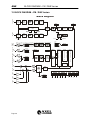
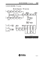
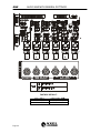
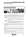
1
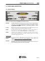
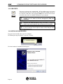
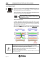
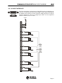
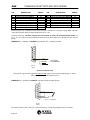
Falcon 50 FM/TV 6 Band DIGITAL audio PROCESSOR Operating manual (Rev. 2.0) PART ONE: INSTALLATION Sede BOLOGNA: Via Caduti Di Sabbiuno 6/F – 40011 Anzola Emilia - Bologna - Italy Tel. +39 051 736555 - Fax. +39 051 736170 Sede BERGAMO: Via Italia 1 – 24030 Medolago (Bg) – Italy e-mail: [email protected] - web site: www.axeltechnology.com FOREWORD ENG 1 FOREWORD From all of us at Axel Technology, thank you for choosing the Falcon 50 digital audio processor. A great deal of effort went into the design and construction of this precision device. With proper installation and calibration the processor will give you the most accurate results for audio processing and modulation. Take the time to go through the steps provided in this manual to ensure you get the most out of your equipment. Used properly, the Falcon 50 will give you many years of enjoyment. Measurements of the Falcon 50 yield excellent results by any standards. However, the Falcon 50 audio quality can not always be represented only by measures. We therefore invite You to a complete and enjoyable listening session... Page 3 ENG FOREWORD For your own safety and to avoid invalidation of the warranty all text marked with these Warning Symbols should be read carefully. Information in this manual is subject to change without notice and does not represent a commitment on the part of the vendor. Axel Technology shall not be liable for any loss or damage whatsoever arising from the use of information or any error contained in this manual, or through any mis-operation or fault in hardware contained in the product. It is recommended that all maintenance and service on the product should be carried out by Axel Technology or its authorised agents. Axel Technology cannot accept any liability whatsoever for any loss or damage caused by service, maintenance or repair by unauthorised personnel. Page 4 TABLE OF CONTENTS ENG 2 TABLE OF CONTENTS FOREWORD .............................................................................................................................................. 3 TABLE OF CONTENTS............................................................................................................................. 5 INTRODUCTION ........................................................................................................................................ 6 3.1 APPROACHING AN FM AUDIO PROCESSOR.............................................................................................. 9 4 INSTALLATION CONSIDERATIONS ..................................................................................................... 10 5 SAFETY WARNINGS / ISTRUZIONI PER LA SICUREZZA................................................................... 11 6 SAFETY WARNINGS .............................................................................................................................. 12 7 CONSIGNES DE SÉCURITÉ IMPORTANTES ....................................................................................... 13 8 ISTRUZIONI IMPORTANTI PER LA SICUREZZA.................................................................................. 14 9 WICHTIGE SICHERHEITSHINWEISE .................................................................................................... 15 10 INSTRUCCIONES IMPORTANTES DE SEGURIDAD ........................................................................ 16 11 UNPACKING AND INSPECTION ........................................................................................................ 17 12 FIRST INSTALLATION RECOMMENDATIONS ................................................................................. 18 12.1 POWER SUPPLY CABLE ............................................................................................................................... 18 12.2 AC MAINS VOLTAGE SETTING (230 V / 115 V) ......................................................................................... 18 12.3 FUSE REPLACEMENT................................................................................................................................... 19 12.4 PROTECTION AGAINST LIGHTNING......................................................................................................... 19 12.5 VENTILATION................................................................................................................................................ 19 13 BLOCK DIAGRAM – FM / DAB Version............................................................................................. 20 14 BLOCK DIAGRAM – TV version ........................................................................................................ 21 15 AUDIO AND MPX GENERAL SETTINGS ........................................................................................... 22 15.1 AUDIO INPUT IMPEDANCE ......................................................................................................................... 22 15.2 MPX OUTPUT SETTINGS (ONLY FM VERSION) ............................................................................................ 23 16 FRONT PANEL DESCRIPTION........................................................................................................... 25 16.1 ‘BLIND VERSION’ ......................................................................................................................................... 25 16.2 LCD VERSION ................................................................................................................................................ 26 17 REAR PANEL DESCRIPTION............................................................................................................. 27 18 AUDIO INPUT AND OUTPUTS ........................................................................................................... 29 18.1 ANALOG AUDIO INPUT ............................................................................................................................... 29 18.2 ANALOG AUDIO OUTPUT ........................................................................................................................... 29 18.3 IN CASE OF UNBALANCED CONNECTIONS… ........................................................................................ 29 18.4 NOTES ON AUDIO CABLES ......................................................................................................................... 30 18.5 DIGITAL AUDIO INPUT ................................................................................................................................ 30 18.6 CONVERTING BETWEEN AES/EBU AND S/PDIF INTERFACES ........................................................................... 30 18.7 DIGITAL AUDIO OUTPUT ............................................................................................................................ 30 18.8 DIGITAL AUDIO SYNCHRONIZATION INTERFACE ............................................................................... 31 18.9 FRONT HEADPHONE SOCKET .................................................................................................................... 31 19 COMMUNICATION PORTS AND GPI/O WIRING............................................................................... 32 19.1 SERIAL PORT ................................................................................................................................................. 32 19.2 CONNECTING A DIAL-UP MODEM ............................................................................................................ 33 19.3 USB PORTS ..................................................................................................................................................... 34 19.4 INSTALLING USB DRIVERS ........................................................................................................................ 34 19.5 ETHERNET PORT*......................................................................................................................................... 36 19.6 GP INPUT INTERFACE .................................................................................................................................. 37 19.7 GP OUTPUT INTERFACE .............................................................................................................................. 39 19.8 MPX AND AUX CONNECTIONS (AVAILABLE ONLY ON FM VERSION) ........................................................ 40 20 MONITORING THE FALCON 50 FROM A ‘PDA’ ............................................................................... 41 21 ‘LCD’ VERSION - FRONT PANEL OPERATION................................................................................ 43 21.1 HOW TO BROWSE THE MENU .................................................................................................................... 43 21.2 HOW TO ADJUST THE HEADPHONE VOLUME........................................................................................ 44 21.3 HOW TO CHANGE THE CURRENT AUDIO PRESET CURVE................................................................... 45 21.4 IMPORTANT NOTICE ABOUT ACCESSING THE FRONT PANEL........................................................... 46 22 INSTALLING THE REMOTE CONTROL SOFTWARE ....................................................................... 47 23 FIRMWARE UPGRADE PROCEDURE ............................................................................................... 48 1 2 3 Page 5 ENG 3 INTRODUCTION INTRODUCTION Congratulations on your purchase of the Falcon 50. The Axel Technology design team is confident you will enjoy the outstanding performance of that processor for many years. In case you are interested in technical details, what follows is a brief outline of some of the key technologies in your new processor. A brief overview Relying on Axel Technology’s extensive know-how in audio processing techniques, the Falcon 50 has been designed and built using a new approach that incorporates the most up-to-date components and technologies. Its efficient design allows the Falcon 50 to produce top-level results in a cost-effective way. The largest control set allows you to paint a truly unique and competitive on-air sound: from detailed and flat to heavy and loud. Its exceptional audio quality is maintained even at extreme settings. The largest connection capabilities Whether your audio system contains analog, digital or both formats, the Falcon 50 can be configured to fit in perfectly. A sophisticated module allows flexible switching between inputs, e.g. for emergency purpose. Fail-safe operation is assured by an internal bypass on all the audio and MPX I/O circuits. Two Composite Baseband Outputs are provided, each with independent level control. The MPX clipping stage is user-enable and adjustable. MPX power can be limited accordingly to ITU R-BS 412 Specification. Two serial RS232 ports, an USB port and a TCP/IP Ethernet connection (the latter available as an option) permit remote control and monitoring from almost any location through the use of a standard PC and the dedicated control software which comes with the unit. User-friendly controls Falcon 50 set-up is quick and easy, thanks to a wizard based on less/more controls. User-configurable remote control functions (including preset programming) are available through optocoupled inputs. For more convenience, a complete day-part automation is also completely self-contained. Control from anywhere The Falcon 50 can be remotely controlled, either from a locally attached computer, or from anywhere in the world. There are many ways to do this. - Using Falcon 50’s IP connection or modem connection you can control processor from anywhere in the world using the provided remote Control Software. - Falcon 50’s serial and USB interfaces allow you to connect any PC running the provided remote Control Software. - Falcon50’s programmable TTL inputs give you six “contact closure” inputs that can be used to control certain functions, like ‘switch audio input’ or ‘change audio curve’. State-of-art circuitation and plenty of headroom Falcon 50’s analog and digital audio input and output circuits are state-of-the-art for high quality, low noise and low distortion audio. The processor’s levels on analog input assure plenty of headroom for all applications without the need for audio limiters. Professional quality AES/EBU digital audio input and output, with internal high-quality rate converters are standard. Page 6 INTRODUCTION ENG Built-in automatic audio changeover The Falcon 50 features two audio inputs: analog and digital. The selection between inputs may be achieved manually or the programme source may be forced to either input Analog or input Digital by activating one of six GP Input, accordingly to Source Selection menu. The Falcon 50 also incoporates an audio detector stage, which can be used to automatically select between two identical stereo programme paths (Analog or Digital), in the event the main program runs underthreshold (set at – 35 dB), extinguishes or the difference on levels between Left and Right channels exceeds 20 dB. Once the Falcon 50 has switched from Main to Stand-by input, the Main input may be kept monitored till the Main audio input resumes. Also when Main audio appears, a settable time may be awaited before inverse switching (from B to A) is performed. Two versions available: ‘blind’ panel or double-LCD panel The Falcon 50 comes in two versions. The LCD version is fitted with two large LCD screens, showing inputs and output meters together with main settings indication, current processing curve, date and time. When pressing the large Jog/Wheel, the left screen switch to the block diagram, thus allowing to configure and set each working and configuration parameter. The right screen still keep to display the levels associated to the processor stage You are browsing, so that the control on the emission is never missed. The LCD front panel gives full access to each configuration and working parameters without need for dedicated Pc Control software. The ‘blind’ version is especially designed for those users, who only need to remotely control the processor from the Pc, with no needs for local control from the front panel. On the front panel, however, some LEDs show correct operation and possible Alarm status. An USB socket and a Headphone socket are also fitted for easy connection, respectively, to a Pc or to a pair of headphones. VERSIONS AVAILABLE DESCRIPTION FALCON 50 FM Digital audio processor 6 bands for FM broadcasting Digital audio processor 6 bands for FM broadcasting with double front LCD display FALCON 50 FM - LCD FALCON 50 TV FALCON 50 TV - LCD Digital audio processor 6 bands for TV audio broadcasting Digital audio processor 6 bands for TV audio broadcasting with double front LCD display OPTIONAL FEATURES DESCRIPTION TCP –IP The TCP IP interface allows users to view/take control of Falcon 50 from any Windows machine networked with the processor. NOTE: the present manual describes the processor in its complete configuration. Depending on the chosen configuration and on the chosen options, Yr actual equipment might not provide some of the here-below described features or controls. Page 7 ENG Page 8 INTRODUCTION INTRODUCTION 3.1 ENG APPROACHING AN FM AUDIO PROCESSOR An audio processor is a nonlinear process, that is, even if the ouput signal might be slightly more attractive in respect to the input signal, it has surely more distortion respect to the input. For this reason, always try to use the cleanest possible audio material to get the cleanest ouput audio and remember that the correct adjustment of a multiband processor is a quite complicated task, so, don’t be frustrated if after thirty minutes you still cannot get your sound. Remember also that “extreme loudness” settings are well suited only for certain kinds of music (pop, disco, rap…) while are awful for other kinds of music; so always adapt the processor to the format of your radio. General settings often sound well with most music formats even if they have not the same loudness. The output sound is always a trade-off between loudness distortion and cleaness and you must choose the trade-off between them according your taste. Another last tip is that you might avoid the use of high stereo expander levels expecially with low bitrate MP3s; MPEG compression puts a lot of “trash” into the stereo image so, often, enhancing the stereo image you could enhance just “MPEG noise” (a sort of “tingling” you may hear at medium-high frequencies). Last recommendation is to use a good quality audio board with a “flat” output, that is no further bass or treble equalization must be added. This is the only way you may expect to have a good peak control and a satisfactory audio quality. Page 9 ENG INSTALLATION CONSIDERATIONS 4 INSTALLATION CONSIDERATIONS Installing the Falcon 50 requires a bit more than mounting it in the rack, connecting some cables, and then putting it on the air. Among the factors you should consider are: 1. Monitor Location. You should have a good location in which the system, once on the air, can be monitored. We suggest a good tuner, with good reception, feeding a set of studio monitor speakers to be sufficient. While car radio and other “typical listener situation” settings are important, they should not be the main reference points. 2. Good, Clean Source Material. If you are using poor source material, or poor performing playback equipment, you will not get maximum sonic benefit from your equipment. Anomalies that you perceive to be processing problems, may be source problems that the processing is exaggerating! Make sure that you start out with a good first step - good source material! 3. Mic Processing. This may appear trivial, but the perceived sound of “live” voices over the air can change dramatically with different processing systems. Whatever the effect your on-air microphones will probably change when you change your processing. If you utilize mic processing, you may have to adjust it to suit the operation of the new processing system. Most announcers develop a “comfort zone” with respect to the sound of their voice over the air. When that “comfort zone” is changed or modified, the common response is that something is wrong. Mic processing can be a very important part of your overall station sound. 4. Operating Levels. This is another simple area where trouble can develop. Make sure the input and output levels of the processor are at the operating at the proper level within your system. Equipment internal Clock is powered by a capacitor instead of a traditional battery. The capacitor keeps the clock operating and protects the system memory to prevent the loss of stored programs during power failure around one week long (depending on the environmental conditions). Capacity charge needs at least 30’ of normal operation. Clock tolerance might amount to about 1 sec per day. A correct installation and an optimum level setting are crucial for a good operating and the exploitation of all the equipment capabilities. Please pay attention to all notes contained in the user manual. Page 10 SAFETY WARNINGS / ISTRUZIONI PER LA SICUREZZA ENG 5 SAFETY WARNINGS / ISTRUZIONI PER LA SICUREZZA SAFETY WARNINGS CONSIGNES DE SÉCURITÉ IMPORTANTES ISTRUZIONI IMPORTANTI PER LA SICUREZZA WICHTIGE SICHERHEITSHINWEISE INSTRUCCIONES IMPORTANTES DE SEGURIDAD (Rel. 1.3) Page 11 ENG 6 SAFETY WARNINGS SAFETY WARNINGS The installation and servicing instructions in this manual are for use by qualified personnel only. - Read All Instructions. All safety and operating instructions must be read before operating the product. They also must be retained for future reference, as it contains a number of useful hints for determining the best combination of equipment settings for Yr particular application. - Heed All Warnings. All warnings on the product and those listed in the operating instructions must be adhered to. - Heat. This product must be situated away from any heat sources such as radiators or other products (including power amplifiers or transmitters) that produce heat. - Power Sources. This product must be operated from the type of power source indicated on the marking label and in the installation instructions. If you are not sure of the type of power supplied to your facility, consult your local power company. Make sure the AC main voltage corresponds to that indicated in the technical specifications. If a different voltage (ex. 110/115 VAC) is available, open the equipment closure and set the voltage switch on the main supply circuit, located behind the AC socket - Power Cord Protection. Power supply cords must be routed so that they are not likely to be walked on nor pinched by items placed upon or against them. Pay particular attention to the cords at AC wall plugs and convenience receptacles, and at the point where the cord plugs into the product - Use only with a cart, stand, tripod, bracket, or table specified by the manufacturer, or sold with the apparatus. When a cart is used, use caution when moving the cart/apparatus combination to avoid injury from tip-over. - Lightning. For added protection for this product during a lightning storm, or when it is left unattended and unused for long periods of time, unplug it from the AC wall outlet and the audio connections. This will prevent damage to the product due to lightning and power line surges - Installation. Configuration and installation should only be carried out by a competent installation engineer - Cabling. Using high quality wires, well protected. Make sure the cable integrity. This symbol alerts you to the presence of dangerous voltage inside the closure – voltage which may be sufficient to constitute a risk of shock. Do not perform any servicing other than that contained in the operating instructions. Refer all servicing to qualified personnel The exclamation point within an equilateral triangle is intended to alert the user to the presence of important operating and maintenance (servicing) instructions in the literature accompanying the appliance. Do not change the voltage setting or replace the mains fuse without first turning the unit off and unplugging the mains cord Make sure the AC main voltage corresponds to that indicated in the technical specifications. THIS APPARATUS MUST BE EARTHED ! To avoid risk of fire use the correct value fuse, as indicated on the label stuck on the right side of the unit. This apparatus uses a single pole mains switch and does therefore not separate the unit completely from the mains power. To completely separate from mains power (f.i. in the event of danger) unplug mains power cord. As the MAINS plug is the disconnect device, the disconnect device shall remain readily operable. Page 12 CONSIGNES DE SÉCURITÉ IMPORTANTES 7 ENG CONSIGNES DE SÉCURITÉ IMPORTANTES - Lire ces consignes - Conserver ces consignes - Observer tous les avertissements - Suivre toutes les consignes - Ne pas utiliser cet appareil à proximité de l’eau - Ne pas obstruer les ouvertures de ventilation. Installer en respectant les consignes du fabricant - Ne pas installer à proximité d'une source de chaleur telle qu'un radiateur, une bouche de chaleur, un poêle ou d'autres appareils (dont les amplificateurs) produisant de la chaleur. - Ne pas annuler la sécurité de la fiche de terre, la troisième branche est destinée à la sécurité. Si la fiche fournie ne s'adapte pas à la prise électrique, demander à un électricien de remplacer la prise hors normes. - Protéger le cordon d'alimentation afin que personne ne marche dessus et que rien ne le pince, en particulier aux fiches, aux prises de courant et au point de sortie de l’appareil - Utiliser uniquement les accessoires spécifiés par le fabricant - Utiliser uniquement avec un chariot, un support ou une table spécifié par le fabricant ou vendu avec l’appareil. Si un chariot est utilisé, déplacer l’ensemble chariot–appareil avec précaution afin de ne pas le renverser, ce qui pourrait entraîner des blessures - Débrancher l’appareil pendant les orages ou quand il ne sera pas utilisé pendant longtemps. - Confier toute réparation à du personnel qualifié. Des réparations sont nécessaires si l’appareil est endommagé d’une façon quelconque, par exemple: cordon ou prise d’alimentation endommagé, liquide renversé ou objet tombé à l’intérieur de l’appareil, exposition de l’appareil à la pluie ou à l’humidité, appareil qui ne marche pas normalement ou que l’on a fait tomber. - NE PAS exposer cet appareil aux égouttures et aux éclaboussements. Ne pas poser des objets contenant de l'eau, comme des vases, sur l'appareil Ce symbole indique la présence d'une tension dangereuse dans l'appareil constituant un risque de choc électrique. Ce symbole indique que la documentation fournie avec l'appareil contient des instructions d'utilisation et d'entretien importantes. Avant de modifier le commutateur de changement de tension ou replacer le fusible il faut débrancher l’appareil de la prise électrique. Pendant son usage, l’appareil doit etre branchee à la prise de terre Utiliser le fusible principal AC avec le valeur qui est indiquée sur l'étiquette collée sur le coffret. Assurez-vous que la tension principale AC correspond à celle indiquée dans les spécifications techniques. L’interrupteur d’alimentation interrompt un pôle du réseau d’alimentation excepté le conducteur de terre de protection. En cas de danger, debrancher le cordon d'alimentation. Parce que la prise du réseau de alimentation est utilisée comme dispositif de déconnexion, ce dispositif doit demeuré aisément accessible Page 13 ENG ISTRUZIONI IMPORTANTI PER LA SICUREZZA 8 ISTRUZIONI IMPORTANTI PER LA SICUREZZA - Leggere le presenti istruzioni - Conservare queste istruzioni - Osservare tutte le avvertenze - Seguire scrupolosamente tutte le istruzioni - Non usare questo apparecchio in prossimità di acqua - Non ostruire alcuna apertura per il raffreddamento. Installare l’apparecchio seguendo le istruzioni - Non installare l'apparecchio accanto a fonti di calore quali radiatori, aperture per l'afflusso di aria calda, forni o altri apparecchi (amplificatori inclusi) che generino calore - Non rimuovere il terminale di connessione a terra sul cordone di alimentazione: esso ha lo scopo di tutelare l’incolumità dell’utilizzatore. Se la spina in dotazione non si adatta alla presa di corrente, rivolgersi ad un elettricista per far eseguire le modifiche necessarie. - Evitare di calpestare il cavo di alimentazione o di comprimerlo, specialmente in corrispondenza della spina e del punto di inserzione sull’apparato. - Utilizzare solo dispositivi di collegamento e gli accessori specificati dal produttore. - Utilizzare l’apparecchio solo con un carrello, un sostegno, una staffa o un tavolo di tipo specificato dal produttore o venduto insieme all’apparecchio. Se si utilizza un carrello, fare attenzione negli spostamenti per evitare infortuni causati da ribaltamenti del carrello stesso. - Scollegare l’apparecchio dalla presa di corrente durante i temporali o quando inutilizzato a lungo - Per qualsiasi intervento, rivolgersi a personale di assistenza qualificato. È’ necessario intervenire sull’apparecchio ogniqualvolta si verificano danneggiamenti di qualsiasi natura. Ad esempio, la spina o il cavo di alimentazione sono danneggiati, è entrato liquido nell’apparecchio o sono caduti oggetti su di esso, l’apparecchio è stato esposto alla pioggia o all’umidità, non funziona normalmente o è caduto. - Non esporre a sgocciolamenti o spruzzi. Non appoggiare sull'apparecchio oggetti pieni di liquidi, ad esempio vasi da fiori. Questo simbolo indica la presenza di alta tensione all'interno dell'apparecchio, che comporta rischi di scossa elettrica. Questo simbolo indica la presenza di istruzioni importanti per l'uso e la manutenzione nella documentazione in dotazione all'apparecchio. Non sostituire il fusibile o cambiare la tensione di alimentazione senza aver prima scollegato il cordone di alimentazione. L’APPARATO DEVE ESSERE CONNESSO A TERRA. Sostituire il fusibile generale con uno di identico valore, come indicato sulla etichetta applicata sul mobile dell’apparato Assicurarsi che la tensione di rete corrisponda a quella per la quale è configurato l’apparecchio Questo apparato utilizza un interruttore di alimentazione di tipo unipolare e l’isolamento dalla rete elettrica non è pertanto completo. Per ottenere un isolamento totale (ad esempio in caso di pericolo), scollegare il cordone di alimentazione. Inoltre, poichè la spina di alimentazione è utilizzata come dispositivo di sezionamento, essa deve restare facilmente raggiungibile Page 14 WICHTIGE SICHERHEITSHINWEISE ENG 9 WICHTIGE SICHERHEITSHINWEISE - Diese Hinweise LESEN - Diese Hinweise AUFHEBEN - Alle Warnhinweise BEACHTEN - Alle Anweisungen BEFOLGEN - Dieses Gerät NICHT in der Nähe von Wasser verwenden - KEINE Lüftungsöffnungen verdecken. Gemäß den Anweisungen des Herstellers einbauen - Nicht in der Nähe von Wärmequellen, wie Heizkörpern, Raumheizungen, Herden oder anderen Geräten (einschließlich Verstärkern) installieren, die Wärme erzeugen - Die Schutzfunktion des Schukosteckers NICHT umgehen. Bei Steckern für die USA gibt es polarisierte Stecker, bei denen ein Leiter breiter als der andere ist; US-Stecker mit Erdung verfügen über einen dritten Schutzleiter. Bei diesen Steckerausführungen dient der breitere Leiter bzw. der Schutzleiter Ihrer Sicherheit. Wenn der mitgelieferte Stecker nicht in die Steckdose passt, einen Elektriker mit dem Austauschen der veralteten Steckdose beauftragen - VERHINDERN, dass das Netzkabel gequetscht oder darauf getreten wird, insbesondere im Bereich der Stecker, Netzsteckdosen und an der Austrittsstelle vom Gerät - NUR das vom Hersteller angegebene Zubehör und entsprechende Zusatzgeräte verwenden. - NUR in Verbindung mit einem vom Hersteller angegebenen oder mit dem Gerät verkauften Transportwagen, Stand, Stativ, Träger oder Tisch verwenden. Wenn ein Transportwagen verwendet wird, beim Verschieben der Transportwagen-Geräte- Einheit vorsichtig vorgehen, um Verletzungen durch Umkippen - Das Netzkabel dieses Geräts während Gewittern oder bei längeren Stillstandszeiten aus der Steckdose ABZIEHEN. - Alle Reparatur- und Wartungsarbeiten von qualifiziertem Kundendienstpersonal DURCHFÜHREN LASSEN. Kundendienst ist erforderlich, wenn das Gerät auf irgendwelche Weise beschädigt wurde, z.B. wenn das Netzkabel oder der Netzstecker beschädigt wurden, wenn Flüssigkeiten in das Gerät verschüttet wurden oder Fremdkörper hineinfielen, wenn das Gerät Regen oder Feuchtigkeit ausgesetzt war, nicht normal funktioniert oder fallen gelassen wurde. - Dieses Gerät vor Tropf- und Spritzwasser SCHÜTZEN. KEINE mit Wasser gefüllten Gegenstände wie zum Beispiel Vasen auf das Gerät STELLEN. Dieses Symbol zeigt an, dass gefährliche Spannungswerte, die ein Stromschlagrisiko darstellen, innerhalb dieses Geräts auftreten. Dieses Symbol zeigt an, dass das diesem Gerät beiliegende Handbuch wichtige Betriebs- und Wartungsanweisungen enthält. Vor Änderung der Netzspannung oder Sicherungswechsel Netzkabel trennen. Das Gerät muss für den Betrieb geerdet werden. Hauptsicherung nur mit einer gleichwertigen austauschen (s. entsprechende Etikette). Vor Einschalten Netzspannungseinstellung am Gerät überprüfen bzw. anpassen. Inpoliger Netzschalter. In Notfälle oder für Wartungsarbeiten Netzkabel trennen. Der Netzstecker fungiert auch als Trennelement muss deshalb zugänglich bleiben Page 15 ENG INSTRUCCIONES IMPORTANTES DE SEGURIDAD 10 INSTRUCCIONES IMPORTANTES DE SEGURIDAD - LEA estas instrucciones - CONSERVE estas instrucciones - PRESTE ATENCION a todas las advertencias. - SIGA todas las instrucciones - NO utilice este aparato cerca del agua - NO obstruya ninguna de las aberturas de ventilación. Instálese según lo indicado en las instrucciones del fabricante - No instale el aparato cerca de fuentes de calor tales como radiadores, registros de calefacción, estufas u otros aparatos (incluyendo amplificadores) que produzcan calor - NO anule la función de seguridad del enchufe polarizado o con clavija de puesta a tierra. Un enchufe polarizado tiene dos patas, una más ancha que la otra. Un enchufe con puesta a tierra tiene dos patas y una tercera clavija con puesta a tierra. La pata más ancha o la tercera clavija se proporciona para su seguridad. Si el toma corriente no es del tipo apropiado para el enchufe, consulte a un electricista para que sustituya el toma corriente de estilo anticuado - PROTEJA el cable eléctrico para evitar que personas lo pisen o estrujen, particularmente en sus enchufes, en los toma corrientes y en el punto en el cual sale del aparato - UTILICE únicamente los accesorios especificados por el fabricante - UTILICESE únicamente con un carro, pedestal, escuadra o mesa del tipo especificado por el fabricante o vendido con el aparato. Si se usa un carro, el mismo debe moverse con sumo cuidado para evitar que se vuelque con el aparato - DESENCHUFE el aparato durante las tormentas eléctricas, o si no va a ser utilizado por un lapso prolongado. - TODA reparación debe ser llevada a cabo por técnicos calificados. El aparato requiere reparación si ha sufrido cualquier tipo de daño, incluyendo los daños al cordón o enchufe eléctrico, si se derrama líquido sobre el aparato o si caen objetos en su interior, si ha sido expuesto a la lluvia o la humedad, si no funciona de modo normal, o si se ha caído. - NO exponga este aparato a chorros o salpicaduras de líquidos. NO coloque objetos llenos con líquido, tales como floreros, sobre el aparato . Este símbolo indica que la unidad contiene niveles de voltaje peligrosos que representan un riesgo de choques eléctricos. Este símbolo indica que la literatura que acompaña a esta unidad contiene instrucciones importantes de funcionamiento y mantenimiento. Antes de cambiar la alimentacion de voltaje o de cambiar el fusible, desconecte el cable de alimentacion. Para reducir el riesgo de descargas electricas, esta unidad debe ser conectada a tierra. Remplaze el fusible con lo mismo, que corresponde a lo indicado en el panel del equipo. Antes de encender, controlar que la linea de alimentacion de voltaje corresponda a la indicada El interruptor de alimentación es unipolar. En el caso de peligro, desconecte el cable de alimentación. Porque la clavija de conexion a red sirve por la desconection de la unidad, la clavija debe ser ubicada en proximidad de la unidad Page 16 UNPACKING AND INSPECTION ENG 11 UNPACKING AND INSPECTION Your equipment was packed carefully at the factory in a container designed to protect the unit during shipment. Nevertheless, we recommend making a careful inspection of the shipping carton and the contents for any signs of physical damage. Damage & Claims If damage is evident, do not discard the container or packing material. Contact your carrier immediately to file a claim for damages. Customarily, the carrier requires you, the consignee, to make all damage claims. It will be helpful to retain the shipping documents and the waybill number. Save all packing materials! If You should ever have to ship the unti (e.g. for servicing), it is best to ship it in the original carton with its packing materials because both the carton and packing material have been carefully designed to protect the unit. Under normal conditions no user maintenance or calibration are required. Internal links and preset controls may be set to configure the unit during installation. Any service work required should be carried out by qualified service personnel only. We are able to offer further product support through our worldwide network of approved dealers and service agents. To help us provide the most efficient service please would you keep a record of the unit serial number, and date and place of purchase to be quoted in any communication regarding this product. The actual equipment Serial Number is indicated on the silver label stuck on the rear panel of the equipment closure. Tools And Equipment Needed Only standard technician’s tools are required to install this equipment. Page 17 ENG FIRST INSTALLATION RECOMMENDATIONS 12 FIRST INSTALLATION RECOMMENDATIONS 12.1 POWER SUPPLY CABLE A power supply cable of approx. 2 mt length is supplied with the device, which has a moulded IEC plug attached – this is a legal requirement. The type of plug for the power supply depends on the country in which it is delivered. If for any reason, you need to use this appliance with a different plug, you should use the following wiring guidelines in replacing the exsisting plug with the new one: Earth Neutral (N) Live (L) Green, or green and yellow Blue Brown Supply cables should be laid in such a manner that one does not step or walk on them. They should not be squashed by any objects. THIS EQUIPMENT MUST BE EARTHED. The chassis is always connected to mains earth to ensure your safety: check your mains wiring and earthing before switching on. 12.2 AC MAINS VOLTAGE SETTING (230 V / 115 V) BE SURE THAT THE UNIT IS SET TO THE CORRECT MAINS/LINE VOLTAGE FOR YOUR COUNTRY BEFORE PLUGGING IT INTO THE WALL OUTLET ! The actual Mains voltage is indicated on the label stuck on the equipment closure. Should the type of power at the operation location not be known, please contact your dealer or electricity company. If, for some reason, the unit is to be operated at a mains input voltage which is different to that as supplied, you need to open the top cover and set properly the voltage change-over switch which is located inside, close to the transformer. You also need to replace the AC main fuse, according to information provided on the external label or on the Technical Specifications table at the end of this user manual. CAUTION: TO REDUCE THE RISK OF ELECTRICAL SHOCK, ALWAYS DISCONNECT THE AC MAINS CABLE BEFORE ALTERING THE CHANGE-OVER SWITCH. NO USER SERVICEABLE PARTS INSIDE. REFER SERVICING TO QUALIFIED SERVICE PERSONNEL. Page 18 FIRST INSTALLATION RECOMMENDATIONS ENG 12.3 FUSE REPLACEMENT The power supply socket has an integral fuse drawer containing the AC power fuse and a spare, both of the same value. BEFORE REPLACING THE POWER FUSE, MAKE SURE YOU HAVE THE RIGHT TYPE OF FUSE FOR THE VOLTAGE TO BE PROTECTED. USING WRONG FUSE TYPE WILL RESULT IN INSUFFICIENT PROTECTION. Make sure that the power is switched off and the power cable is disconnected from the equipment. Open the fuse drawer using a small blade screwdriver. Replace the fuse located at the inner position Push the fuse socket back into the original position Perform the set-up under static control conditions. Static charges are likely to completely destroy one or more of the CMOS semiconductors employed in the unit. Static damage will not be covered under warranty. Basic damage prevention consists of minimizing generation, discharging any accumulated static charge on your body and preventing that discharge from being sent to or through any electronic component. Uninsulated dangerous voltage are inside the enclosure, voltage that may be sufficient to constitute a risk of shock. Always disconnect to AC Mains before removing the top cover 12.4 PROTECTION AGAINST LIGHTNING Should the device be put out of action due to being struck by lightning or excess voltage, disconnect it from the power supply without delay. Do not reconnect until the device has been checked. If in doubt contact the technical support service. Make sure there is suitable lightning protection to protect the device. Alternatively you should disconnect all connectors from the device during a storm or when the device is going to be unsupervised or not used for a longer period of time. These measures will protect against damage by lightning or excess voltage. 12.5 VENTILATION The equipment will operate as a free-standing unit without requiring any special cooling arrangement. However, slots and openings in the product are provided for ventilation. They ensure reliable operation of the product, keeping it from overheating. These openings must not be blocked nor covered during operation. YOU MUST LEAVE AT A MINIMUM ONE RACK UNIT OF EMPTY SPACE ABOVE THE EQUIPMENT TO ENHANCE VENTILATION AND TO GET A LONGER EQUIPMENT LIFE. Page 19 BLOCK DIAGRAM – FM / DAB Version ENG 13 BLOCK DIAGRAM – FM / DAB Version Block diagram D I G I I T N A L Digital Input 32,44.1,48,96 KHz Hi-Pass 30Hz Input mode switch Phase Rotator Input Selection Command Logic External Signals A N A I L ON G Analog Input 47.5Ks/sec Input mode switch 2-Band AGC Primary Input Selector User Command Hi-Pass 30Hz D I GO I U T T A L Phase Rotator Freq. A N A L O G H E A D P H O N E S O U T OPTIONAL FM-Proc Generator Monitor Input Monitor FM-Proc 6-Band FM-Proc Modulation Input EQ Multiband DAB/IBOC FM-Proc Input FM-Proc Generator Input Stereo Enhancer Mode AD Clipping Point I O DB AOU BCT EQ 6-Band 5-Band 6-Band L I M I T E R E X P A N D E R C O M P R E S S O R Look Ahead Limiter & Expander O U T MO PU X T 1 MO PU X T 2 A U I XN 1 A U I XN 2 A U I XN 3 Page 20 Super Bass MPX Power Limiter Opto Interface FM-Proc Generator Input 1° 2° 3° 4° 5° 6° 1° 2° 3° 4° BLOCK DIAGRAM – TV version ENG 14 BLOCK DIAGRAM – TV version Block diagram - TV version D I G I I TN A L Digital Input 32,44.1,48,96 KHz Input mode switch Reference Adjust Hi-Pass 30Hz Phase Rotator Input Primary Input Selector Selection Command Logic A N A I L ON G External Signals Analog Input 47.5Ks/sec Input mode switch Reference Adjust Low-Pass 15KHz User Command Hi-Pass 30Hz EQ 2-Band AGC Stereo Enhancer Internal Sine Generator Generator Mode Phase Rotator Freq. AD Clipping Point Modulation Input EQ Multiband FM-Proc D I GO I U TT A L A NO A LU OT G H E A DO P HU OT N E S Proc Generator Input Proc Generator Monitor Input Multiband Proc OverShoot Compensator Distorsion Cancelled Clipper Parametric EQ Look Ahead Limiter & Expander Monitor 6-Band 6-Band 5-Band 6-Band Distorsion Cancelled Clipper L I M I T E R E X P A N D E R C O M P R E S S O R Super Bass Opto Interface 1° 2° 3° 4° 5° 6° 1° 2° 3° 4° Page 21 ENG AUDIO AND MPX GENERAL SETTINGS 15 AUDIO AND MPX GENERAL SETTINGS 15.1 AUDIO INPUT IMPEDANCE The analog input impedance may be set to 600Ω, rather than the default 10kΩ Ω, by moving the two jumpers J4 and J5 placed at the back of input XLR connectors (see figure below). Page 22 AUDIO AND MPX GENERAL SETTINGS ENG 15.2 MPX OUTPUT SETTINGS (only FM version) The Falcon 50 is fitted with two MPX outputs with independent level adjustements and three Auxiliary inputs. The AUX input gains may be set to 0 dB or to – 20 dB (1/10 gain) through the J1, J2 and J3 jumpers located just at the back of the respective Bnc connectors. AUX 1 Input: is Factory preset for - 20dB gain. Gain my be altered to 0 dB using J1 jumper AUX 2 input is Factory preset for - 20dB gain. Gain my be altered to 0 dB using J2 jumper AUX 3 input is Factory preset for 0dB gain. Gain my be altered to – 20 dB using J3 jumper Please note, the AUX 1 input allows to inject signals on the OUTPUT 1 only; the AUX 2 input allows to inject signals on the OUTPUT 2 only, while the AUX 3 input allows to inject signals on both outputs. Page 23 AUDIO AND MPX GENERAL SETTINGS ENG M P X SyncOUT MPX Outputs Aux Inputs FACTORY DEFAULT: AUX 1 INPUT AUX 2 INPUT AUX 3 INPUT Page 24 INPUT GAIN - 20dB INPUT GAIN - 20dB INPUT GAIN 0dB FRONT PANEL DESCRIPTION ENG 16 FRONT PANEL DESCRIPTION 16.1 ‘BLIND VERSION’ The processor front panel contains 3 red LEDs with the following meaning: OPERATE this LED normally flickers on when the processor works correctly. It is important in that it gives you a visual indication of how active your system is, and can help ensure that it is working correctly. THE PROCESSOR IS OPERATING NORMALLY WHEN ACTIVITY LED IS FLASHING PC LINK While the PC is properly connected to the procxessor, this LED should be lit up. If this is not the case, then check the connection parameters and cable. ALARM this LED (normally off) lights in the relevant cases set via the control software (f.i. primary audio source failure, Internal Temperature exceeding 60 °C, etc). POWER It displays the power supply presence. If the LED is not lit, make sure the main power source is active, the main switch is on and the connector on the cord is securely mated with the plug on the back panel. Connection ports: HEADPHONE SOCKET Any channel pair that is going through the processor can also be routed to the headphone jack on the front panel using the MONITOR selector switch in the software. Headphone volume is also controlled from the software. USB PORT B Type port, designed for the easiest connection to the processor. Special drivers are needed to be installed on the pc for proper connection. Refer to the Chapter ‘COMMUNICATION PORTS AND GPI/O WIRING’ Page 25 ENG FRONT PANEL DESCRIPTION 16.2 LCD VERSION The Falcon50 front panel consists of a pair of Liquid Crystal Display (LCD), six push buttons and a large knob. The LCDs are 240 x 128 pixel displays. The buttons and the knobs are used to browse the Falcon 50 menu and to configure it. USB socket and Phone jack socket are also fitted on the front panel. <Left Arrow> , <Right Arrow>, <Up Arrow>, <Down Arrow>. They are used to browse between blocks or between lines inside each block. <Phones> this key recall the Headphones volume control, shown on the Left LCD screen. <Esc>: This key selects the previous screen in a sequence of screens. When you use this key to exit a configuration screen, any configuration parameters that were modified will return to their original values. JOG WHEEL Whenever pressed, it enters the configuration menu. Pressing this wheel has the same result as pressing ENTER key on the software. Whenever rotated, it allows to scroll the menu and modify the parameters. Connection ports: HEADPHONE SOCKET Any channel pair that is going through the processor can also be routed to the headphone jack on the front panel using the MONITOR selector switch in the software. Headphone volume is controlled by pushing the associated button (see 4) on the front panel: a specific level menu will be displayed on the Left LCD display screen (1). USB PORT B Type port, designed for the easiest connection to the processor. Special drivers are needed to be installe don the pc for proper connection. Refer to the Chapter ‘COMMUNICATION PORTS AND GPI/O WIRING’ Page 26 REAR PANEL DESCRIPTION ENG 17 REAR PANEL DESCRIPTION 17 I 16 I 15 I 14 I 13 I 12 I AES/EBU AES/EBU S/PDIF CAUTION RISK OF ELECTRIC SHOCK DO NOT OPEN R E M O T E 2 3 1 G P Ethernet C O N T R O L Outputs M P X SyncIN Inputs I 1 1 I 2 USB I 3 2 3 1 Outputs 1 3 2 SyncOUT I 4 MPX Outputs I 5 I 6 I 7 I 8 1 3 2 R Outputs Aux Inputs I 9 I 10 D I G I T A L Inputs L Serial RS-232 S/PDIF 1 3 2 2 3 1 L 2 3 1 A N A L O G R Inputs I 11 ON/OFF Switch, AC MAINS FUSE AND AC POWER RECEPTACLE. main ON/OFF switch, the LED inside switches on/off accordingly. An AC mains fuse is provided which disconnects the Falcon 50 from the wall outlet’s AC power under fault conditions. If this fuse should “blow” for any reason, replace it only with the same value fuse. If it blows a second time, please contact your Axel Technology dealer for service. Two fuses (one for spare) are contained in a small drawer close to the cord receptacle. For 220/230 V AC the fuse is slo-blo 5x20mm rated at 315 mA T; for 110 V AC it is rated at 630 mA T This apparatus uses a single pole mains switch and does therefore not separate the unit completely from the mains power. To completely separate from mains power; unplug mains power cord. Never operate the Falcon 50 with ungrounded outlets: plugging the processor into an ungrounded outlet or defeating the ground pin, can create a potentially hazardous condition. Axel Technology can not be held responsible for problems caused to Falcon 50 or any associated equipment with improper AC connection. 2 RS232 Serial Port: This port is intended for the processor setting and programming by means of the supplied Pc control software application (bidirectional connection). Supported Baud Rate: 19200. A regulat POTS modem may be connected to the same port to, for the remote control of the processor from a telephone line. 3 USB port: Type B connector (1.1 version). It supports full connection to Pcs equipped with USB ports. 4 Sync-out: 19KHz synchronism output at 5Vpp, to lock external equipment (such as RDS coders) 5 MPX OUT 1: main MPX output. Accordingly to the current configuration, the output BNC connector will include the composite / MPX program signal with the RDS / SCA subcarrier mixed into and with or without signals injected from AUX inputs. The output level is set via software. (output available only on FM version) 6 MPX OUT 2: additional MPX output, with independent level control. This output can be reconfigured in software as a Pilot Reference Output useful for RDS (RBDS) subcarrier generators that require an external sync reference. (output available only on FM version) 7 AUX 1 Input: Bnc female connector. Depending on the MPX board configuration, it allow the injection of RDS/SCA or MPX signals from external encoders/generators. The resultant signal is available on Page 27 ENG REAR PANEL DESCRIPTION the Output connectors OUT 1 or OUT 2. Factory preset: - 20dB gain. Gain my be altered to 0 dB (input available only on FM version) 8 AUX 2 input: Bnc female connector. Depending on the MPX board configuration, it allows the injection of RDS/SCA or MPX signals from external encoders/generators. The resultant signal is available on the Output connectors OUT 1 or OUT 2. Factory preset: - 20dB gain. Gain my be altered to 0 dB. (input available only on FM version) 9 AUX 3 input: Bnc female connector. Depending on the MPX board configuration, it allow the injection of RDS/SCA or MPX signals from external encoders/generators. The resultant signal is available on the Output connectors OUT 1 or OUT 2. Factory preset: 0dB gain. Gain my be altered to – 20 dB. (input available only on FM version) 10 ANALOG AUDIO OUTPUT: It provides the L and R processed audio signals on which it is possible to enable/disable pre-emphasis. The level is set via the menu. 11 ANALOG AUDIO INPUT: bi-channel audio input electronically balanced on XLR female. The input level is set via menu. 12 DIGITAL AUDIO INPUT: This has two connectors: use the XLR for balanced AES/EBU coaxial connections and the tos-link for optical S/PDIF connections.The XLR input conforms to the 110 ohm impedance standard using a 3-pin XLR female connector. Use only rated digital audio cables. Ordinary audio cable can cause jitter, resulting in noise or distortion in the audio. 13 DIGITAL AUDIO OUTPUT: This has two connectors: use the XLR for balanced coaxial connections and the tos-link for optical connections. The AES/EBU output conforms to the 110 ohm standard using a 3-pin XLR male connector. It is capable of driving any standard digital audio cable run. Be sure to use only digital audio rated cabling for best results. 14 SYNC IN When running digital audio interface, the Falcon 50 may synchronize to the AES/EBU signal provided to this input. Alternatively, it may synchronize to the regular AES/EBU input signal, or to the default internal crystal oscillator if no digital audio input is present. 15 OPTO INPUT PORT: SubD 15-pin female Interface. It supports 6 optoinsulated “trigger” inputs which can be used to control various Falcon 50 internal functions, such as audio input selection, current processing curve, mix balance between MPX outputs and AUX inputs, etc 16 OPTO OUTPUT INTERFACE: SubD 15-pin male Interface. It supports 4 optoinsulated outputs for various purposes (signalling, alarms, etc). 17 ETHERNET port*. RJ45 (LAN) connector. A TCP/IP connection may be set up with a PC on which the remote control software provided runs. The data exchange is achieved via a simple IP Port Protocol. * available as an option Page 28 AUDIO INPUT AND OUTPUTS ENG 18 AUDIO INPUT AND OUTPUTS Where possible use balanced connections for the audio inputs and outputs to minimise noise pick-up. Avoid running audio cables near to mains or lighting cables or thyristor dimmer units, power supplies etc. These may cause audible hum and buzz. The use of low impedance sources significantly reduces interference pickup. Check the cables for correct wiring to avoid problems with phase reversal and unreliable connection. 18.1 ANALOG AUDIO INPUT The processor features electronically balanced XLR female inputs. 2 3 1 2 3 1 L Pin 1 Pin 2 Pin 3 Gnd Signal Return An hardware bypass directly connect the two input XLRs to the output ones in the event of power failure or processor switched off. R Inputs Factory preset input impedance is 10 kΩ. This impedance may also be set to 600Ω by moving the two internal jumpers on the analog I/O board (see previous chapters). Make sure that the earth connection is good and that earth and audio ground are separated. NOTE: also MONO sources may be connected, refer to software settings. 18.2 ANALOG AUDIO OUTPUT The processor features XLR analog outputs electronically balanced by high-quality buffers, capable of withstanding even low-impedance loads (600Ω), with levels of up to +20 dBu. 1 3 2 L 1 3 2 R Outputs Pin 1 Pin 2 Pin 3 Gnd Signal Return. For output level adjusting, and to change or disable the pre-emphasis setting, please refer to software settings. 18.3 IN CASE OF UNBALANCED CONNECTIONS… In case of unbalanced connections, connect the cold pole (Pin 3) to the ground (Pin 1). The figure here below shows how to wire a male XLR to a Pin Rca connector. Page 29 ENG AUDIO INPUT AND OUTPUTS 18.4 NOTES ON AUDIO CABLES As with all professional audio applications, utmost care should be taken with audio cabling for your Falcon 50. For all balanced audio cabling, only high-quality, shielded twisted-pair audio cables should be used, mated to high-quality XLR connectors. With proper cabling techniques, long lengths can be used, but excess cable should be avoided. Unbalanced audio cable techniques can also be used with the Falcon 50; however, cable lengths should be limited to less than 15 mt, less if in a high RF environment. Only high quality shielded audio cable and connectors should be used. 18.5 DIGITAL AUDIO INPUT The digital input features two connectors: coaxial and optic. Only one connector may be connected at a time to avoid malfunctions (TOSLINK optical connector should be kept covered while not used). XLR female connector is designed for AES/EBU sources (“professional standard” interface), while TOSLINK connector is designed to carry S/PDIF signals (“consumer standard” interface). The digital input automatically recognizes the digital format (AES/EBU, S/PDIF, etc.), the type of connection (optic or coaxial) and can seamlessly handle 32KHz, 44.1KHz, 48KHz and 96KHz sample rates. Coaxial input (on XLR) is transformer balanced, and so highly immune from external disturbances and noise (EMI). Pin 1 Pin 2 Pin 3 Gnd Signal Return 2 3 1 To enable the digital input level, see associated chapter. The Digital Input LED on the front panel indicates while the digital input is active Digital Input 18.6 CONVERTING BETWEEN AES/EBU AND S/PDIF INTERFACES There are a number of differences in the electrical characteristics of AES/EBU and S/PDIF interfaces which in some cases can render them completely incompatible. Although the audio data is the same in both AES/EBU and S/ PDIF interfaces, they are indeed different formats, at least in their subcode. AES converted to coax is NOT S/PDIF, and S/PDIF converted to XLR balanced is NOT AES. For proper performance, AES/EBU input (XLR connector) should therefore not be used for connection to consumer equipment providing S/PDIF format. 18.7 DIGITAL AUDIO OUTPUT The digital output features two connectors: coaxial and optic. Only one connector may be connected at a time to avoid malfunctions. Please keep the tos-link connector covered while not used. The coaxial input (on XLR) is transformer balanced, and so highly immune from external disturbances and noise (EMI). Page 30 AUDIO INPUT AND OUTPUTS Pin 1 Pin 2 Pin 3 S/PDIF 1 3 2 ENG Gnd Signal Return. Outputs 18.8 DIGITAL AUDIO SYNCHRONIZATION INTERFACE AES/EBU S/PDIF 2 3 1 SyncIN 1 3 2 Pin 1 Pin 2 Pin 3 Gnd Signal Return. Outputs The Falcon 50 features three modes of synchronization for AES/EBU output streams. Accordingly to the selected configuration (user-definable via the Pc control software), the processor will disable the on-board PLL and instead use the clock recovered from the AES/EBU receiver at input named ‘SYNC IN’ or the clock recovered from the AES/EBU signal provided at the DIGITAL audio input. 18.9 FRONT HEADPHONE SOCKET The Falcon 50 front panel contains a ¼” jack audio socket for connection to monitoring headphones. The Headphone output will contain the same audio content as provided by the Analog output on XLR connectors at the rear panel. The Headphone volume is controlled from the Main screen of Pc control software on the ‘Blind’ version, while it is controlled by the associated menu on the left screen on the LCD version (see ‘headphone’ button on the Falcon 50 LCD front panel). Headphone impedance should be 70 Ohms or higher. COMMON RIGHT LEFT Page 31 COMMUNICATION PORTS AND GPI/O WIRING ENG 19 COMMUNICATION PORTS AND GPI/O WIRING There are four ways of connection between the Pc running the Remote Control Software and the processor unit: serial RS232, USB, Ethernet and Modem. The first two are called ‘Local Connections’, while the latter two are called ‘Remote Connections’. Only ONE connection can be active at a time. Therefore, even if more than one Pc are simultaneously connected to Falcon 50 (f.i. via USB, Lan, Etc), only one of them will control it. 19.1 SERIAL PORT The processor features an optoisolated serial port for remote control through PC (directly connected or via satellite chain) of all machine functions and parameters. A standard, not crossed serial cable (9p male – 9p female) is provided with the equipment, compatible with all configurations. Serial RS-232 Page 32 RS-232 Serial port features the Tx and Rx signals plus the DTR signal (the latter required for modem connection only). Connect a standard serial cable (not crossed cable) between the RS-232 connector and a serial port connector on the computer running the Control Software. Typically, a DB-9 male to DB-9 female serial cable is required. Supported max Baud Rate: 19200. Cable length should not exceed 30 mt. COMMUNICATION PORTS AND GPI/O WIRING ENG 19.2 CONNECTING A DIAL-UP MODEM a modem may be connected to the the Falcon 50 serial port in order to remotely control the processor through a regulat telephone line and a pc equipped with a modem, too. IN THE EVENT OF MODEM CONNECTION, YOU NEED TO ENABLE THE MODEM INTERFACE FROM THE CONTROL SOFTWARE (see the Communication page). Connect the modem to the Serial Port, on the back of the unit. Please pay attention to the Port configuration: its speed must be set to: - 38400 Baud for Pots dial-up modems - 9600 Baud for GSM modems. A ‘cross’ (NULL-MODEM) CABLE is needed for connection to the modem. The following table shows the wiring diagram for the cable in both case the Modem has 9 pins or 25 Pins female SubD connectors. Also remember to: • On a 25 pin plug connect pin 6 and 8. • On a 9 pin plug connect pin 1 and 6. Pin Pin Pin Pin Falcon 50 side (SubD9 Male) 2 3 4 5 Modem Side (SubD 9p M) Modem Side (SubD 25p M) 3 2 6 and 1 5 2 3 6 and 8 7 Page 33 COMMUNICATION PORTS AND GPI/O WIRING ENG 19.3 USB PORTS The processor features two standard USB – B Type USB 2.0 ports (one located on the Front Panel and one on the Rear Panel). Connect the USB-B connector of the computer’s USB cable to the appropriate USB port on the Falcon 50 unit and connect the other end to an available USB-A port on your computer. USB The USB connection can be operated ONLY with proper drivers installed on Yr Pc. Refer to the next Paragraph for USB driver installation. If you connect The Falcon 50 to a computer via USB port, do NOT disconnect the USB cable while is being accessed by a computer. If you do, you may corrupt the data on the processor memories. The two ports run independently, so that You may keep connected two pcs at the same time, even if only one of them at a time will give control over the processor. 19.4 INSTALLING USB DRIVERS Plug your Falcon 50 USB cable to your PC's USB port. The following message may appear on your PC's Taskbar: The New Hardware Found Wizard should appear: Page 34 COMMUNICATION PORTS AND GPI/O WIRING ENG On the screen above, select "Install from a list or specific location (Advanced)" then click the [Next >] button. On the next screen: - Select "Search for the best driver in these locations" - Check "Include this location in the search:" - Use the [Browse] button to find the USB DRIVER folder (usually C:\Program Files\Axel Technology\Falcon 50 x.y/drivers), unless you chose a different folder when you installed the software) - Click [OK] Click the [Next >] button. The following dialog should appear: When this dialog appears (On XP o.s. system), click the [Continue Anyway] button.. The following dialog should appear: Page 35 ENG COMMUNICATION PORTS AND GPI/O WIRING 19.5 ETHERNET PORT* The Falcon 50 may communicate with one or more host computers on a local area network via an ethernet connection (ethernet port available as an option). The ethernet port operates at 10 or 100 megabits per second, carrying Internet Protocol (IP) packets that conform to the UDP protocol. Ethernet The IP address that the Falcon 50 uses may be assigned manually by the user or chosen by default. See the "Network Configuration" section. The Falcon 50 responds to "ping" requests on its assigned IP address. The default IP Address (i.e factory default) of Falcon 50 network interface (when installed) is 192.168.0.20, with Subnet Mask 255.255.255.0. WIRING CONSIDERATIONS As always, quality CAT-5 cabling should be used. A CAT5 cable is used to connect the network port on the back of the Falcon 50 to a port on a switch, hub or router. It is also possible to connect the Falcon 50 directly to a host computer's ethernet port using a crossover cable. LAN connections are typically limited to 100 meters without a hub, router or switch. When connecting the Falcon 50 to a computer directly (i.e.with no infrastructure), you must use a crossed CAT-5 cable as shown in Figure. When connecting a Falcon 50 to an infrastructure (hub, switch, router...), use a straight-through cable. When powering-up the processor, the Falcon 50 Network interface needs 30 seconds or more for complete auto-setup and inizialization. During this period, no communication with the Pc through the Lan will be possible. The network interface will be unavailabile for the same period (at least 30 seconds) also when altering its IP address. For Network Port configuration You will need to communicate with the processor via RS232 or USB connection. Page 36 COMMUNICATION PORTS AND GPI/O WIRING ENG 19.6 GP INPUT INTERFACE Inputs The Falcon 50 provides a general purpose input (GPI) interface for triggering cues and events. The pinout for the GPI connector (DB-15 15-pin female) is provided in the following chart. All inputs are opto-isolated for reliable operation in a variety of electrical environments. There are six trigger inputs which can be assigned via software to different ‘events’ or actions. +12EXT Rv 4 5 12 1 R 9 2 R 10 INP1 3 R INP2 INP3 INP4 11 INP5 6 R INP6 13 7 R 14 8 R 15 Page 37 ENG PIN 1 2 3 4 5 6 7 8 COMMUNICATION PORTS AND GPI/O WIRING DESCRIPTION Anode of photocoupler input 1 Anode of photocoupler input 2 Anode of photocoupler input 3 + 12 V via 100 Ohm resistor + 12 V via 100 Ohm resistor Anode of photocoupler input 4 Anode of photocoupler input 5 Anode of photocoupler input 6 DIRECT. PIN DESCRIPTION DIRECT. IN IN IN OUT OUT IN IN IN 9 10 11 12 13 14 15 Cathode of photocoupler input 1 Cathode of photocoupler input 2 Cathode of photocoupler input 3 GND Cathode of photocoupler input 4 Cathode of photocoupler input 5 Cathode of photocoupler input 6 IN IN IN / IN IN IN Inside the processor, a 100 ohm resistor connects the pins 4 and 5 to a +12V power supply. When nothing is connected to the GPI input, the input voltage therefore is +12V. Inside the processor, 470 ohm resistors also are inserted on series on each optoisolator anode (see pins 1, 2, 3, 6, 7 and 8) for current limiting. Nominal current on optoisolators is 5 mA, while the max current is 10 mA. EXAMPLE N° 1 –activation of GP INPUT 1 by external TTL (+ 5V DC) command 8 15 GND 9 470 OHM 1 EXTERNAL TTL COMMAND DB-15p MALE (connector internal view) External TTL signal must be applied through a 470 Ω carbon resistor to the photodiode (pins 1 and 9). Max current allowed: 10 mA. Nominal: 5 mA EXAMPLE N° 2 – activation of GP INPUT 1 by clean contact (contact closure) 8 15 12 9 1 INPUT 1 ACTIVATION DB-15p MALE The external switch (clean contact) is used to shortcut pin 1 and pin 4 (having pin 9 and 12 shortcut). Page 38 COMMUNICATION PORTS AND GPI/O WIRING ENG 19.7 GP OUTPUT INTERFACE The Falcon 50 provides a general purpose output (GPO) interface for signalling or controlling external equipment. The pinout for the GPO connector (DB15 – Male) is provided in the following chart. All inputs and outputs are opto-isolated for reliable operation in a variety of electrical environments. There are four outputs. Inputs +12 V Rv 4 5 12 R 1 OUT1 9 R OUT1 2 OUT2 OUT2 10 OUT3 OUT4 R 3 OUT3 11 R 6 OUT4 13 PIN DESCRIPTION DIRECT. PIN DESCRIPTION DIRECT. 1 2 3 4 5 6 7 8 Collector of photocoupler output 1 Collector of photocoupler output 2 Collector of photocoupler output 3 + 12 V via 100 Ohm resistor + 12 V via 100 Ohm resistor Collector of photocoupler output 4 N.C. N.C. OUT OUT OUT OUT OUT OUT / / 9 10 11 12 13 14 15 Emitter of photocoupler output 1 Emitter of photocoupler output 2 Emitter of photocoupler output 3 GND Emitter of photocoupler output 4 N.C. N.C. OUT OUT OUT / IN / / Each optoisolator is capable of sinking up to 60 mA of current. OUTPUTS # 1 AND # 2 can be associated to a variety of events (Temperature exceeding 60 or 70 Celsius Degrees, Failures one audio inputs, etc) in order to provide ALARM signallings to external devices by means of Contact closures. Ref. to the User Manual – PART TWO OUTPUTS # 3 AND # 4 are directly driven via software from external controlling devices or systems (such as automated radio systems) running a suitable Remote Control protocol. Page 39 ENG COMMUNICATION PORTS AND GPI/O WIRING 19.8 MPX AND AUX CONNECTIONS (available only on FM version) The AUX 1, AUX2 and AUX 3 inputs (BNC connector, 10 kΩ impedance) allow external signals (tipically RDS) from external encoders to be injected on the MPX output of the processor. The input gain of the injected signals may be set by means of J1, J2 and J3 jumpers to 0 dB or to – 20 dB. Factory preset is - 20dB gain for AUX 1 and AUX 2, while AUX 3 is factory preset to 0 dB gain. Anyway, gains may be altered to 0 dB (- 20 dB) by moving the respective Jumpers J1, J2 and J3 on the MPX output board. The processor can mix SCA signals of any frequency with its own MPX signal, as long as the former are compatible with the composite stereo signal and RDS signal spectra. The MPX OUT 1 and MPX OUT 2 (BNC connector) provide the FM composite signal + any RDS signal (internally generated or injected from an external encoder) and SCA signal. MPX OUT 2 output can be reconfigured in software as a Pilot Reference Output useful for RDS (RBDS) subcarrier generators that require an external sync reference. Two attenuation switches (fully configurable) are provided on the processor to deal with changing RDS/SCA input signals. Using the attenuators (applied to the internally sourced MPX signal) will reduce the overall level of the signal output from the processor. See the Chapter (MPX OUTPUT calibration & Setup). Remarks: • The stereo multiplex output level is adjusted by software. Factory preset is 0 dBm, i.e. approximately 2.2 Vpp. • The output impedance of the BNC jack is approximately 10 ohms sourced by an output driver capable to drive 600 Ohm loads (typical). Maximum performance is achievable when using up to 10 meters of RG-58 cable. Alternatively, 75 Ohm cable may also used for short runs. • Contrary to Left / Right audio outputs, pre-emphasis is always present on the MPX output and you can NOT disable it. Nevertheless, You may set the pre-emphasis time to 50 or 75µ sec. • • • The 19 kHz pilot phase and level may be adjusted via the control software. MPX Out provide various reference tones consisting for easier transmitting chain set-up. To enable the reference tone, see Pc control software operation Each MPX output is individually buffered so that a short circuit on one output will not affect the other. The SYNC OUT (BNC connector) outputs a 19KHz / 5Vpp square wave for external equipment synchronization (i.e. RDS encoders). The Sync output must be enabled via the control software Page 40 MONITORING THE FALCON 50 FROM A ‘PDA’ ENG 20 MONITORING THE FALCON 50 FROM A ‘PDA’ The Falcon 50 comes with a free software to be installed on a PDA (Personal Digital Assistant) computer. A PDA gives easy and immediate access to Falcon 50’s input and output levels and it can be used to switch the curve currently aired and to import/export curves from/to a given location. For those reasons, the PDA becomes an useful tool in particular when used with the processor in its ‘blind’ version. This way, one may get I/O current status, alarm status and one can switch the curve at any time, with no need for a full-featured computer. The PDA may be connected either on the front USB socket, or on the rear USB socket of the Processor. The application for the PDA is provided on the Installation CD ROM, in the PDA Software folder. Installation software is on CAB format. A cabinet CAB file is a compressed file that holds all of the items necessary for installing a program on your Pocket PC. Cab files are extremely portable because you do not need Activesync in order to install a program on your Pocket PC. As long as the .cab file is on your device, then you can perform the install. Page 41 ENG MONITORING THE FALCON 50 FROM A ‘PDA’ To install the software on the PDA, follow these istructions Copy the .cab file (its name will look like Falcon50.arm.CAB) on Your Pc. Perhaps this file will be associated to a compressed file icon, such as WinRar or WinZip starndard icons. Step 1: First step is to copy the .cab file on your Pocket PC. If you have a memory card reader, you can copy it to the card and insert it into your Pocket PC. If you simply download the .cab file from the Web site www.axeltechnology.com you can get it that way. Alternatively, You may use the Activesync tool. Step 2: Navigate to your My Documents folder on your Pocket PC and you'll see the .cab file listed. Step 3: Tap the .cab file one time and it will install! Step4: Run the software application on the PDA from Start - Programs. Once installed and launched the Falcon 50 application, using the PDA keyboard, You may create a Login or just type the Login password. This way, You may easily access the default two pages with all the level meters (see Fig 2). Clicking with the PDA stylus the folder at the top right corner (see picture) You can also enter the Import/Export facility page (see Fig 3). Fig 1 Fig 2 Fig 3 MINIMUM PDA REQUIREMENT CPU RAM Display Resolution Operating System USB Page 42 Samsung S3C2410 266 MHz 64 MB 240x320 QVGA Microsoft PocketPC 2003SE USB Host Port ‘LCD’ VERSION - FRONT PANEL OPERATION ENG 21 ‘LCD’ VERSION - FRONT PANEL OPERATION In the default condition, the two LCD screens will display main settings indication, current processing curve, date and time. 21.1 HOW TO BROWSE THE MENU To browse the menu, press the Jog Wheel (1): the left screen (2) will display the processor block diagram, while the right screen (3) will switch to show input and outputs current level graphs. Use the four arrows (4) and (6) to select the desired configuration block. The selected block will be shown in reverse color. Press the Jog Wheel (1) to access the desired block and its configuration parameters. Use again the arrows (4) and (6) to scroll the parameter list or to move between them. Rotate the Wheel (1) to increase or decrease the values associated to the selected parameters. Once reached the desired value: - press ESC to leave the menu without saving - highlight the OK key at the bottom right corner using the 4 arrows and press the Wheel to CONFIRM. Page 43 ‘LCD’ VERSION - FRONT PANEL OPERATION ENG 21.2 HOW TO ADJUST THE HEADPHONE VOLUME Page 44 - Press the Headphone button (5): the Volume bar will appear. - Rotate the Jog Wheel (1) clockwise or anticlockwise until You reach the desired level - Press the <Down> arrow (6) once, in order to highlight the OK button on the screen - Press the Jog Wheel (1) to confirm the actual level ‘LCD’ VERSION - FRONT PANEL OPERATION ENG 21.3 HOW TO CHANGE THE CURRENT AUDIO PRESET CURVE Starting from the default screens (showing In/Out levels), 1) press the Jog Wheel once. The Block Diagram will appear, with the INPUT SELECT block in evidence 2) using <right> arrow and then the <down> arrow, highlight the PRESETS block: 3) Press the Jog Wheel: the CHANGE PRESET screen will appear. That screen informs about the curve currently On Air and prompts an alternative one (called ‘PRESET’). By rotating the Jog Wheel, scroll the Curve list until the desired one is shown on the screen. At this time, - selecting LOAD the new curve will be put on air and the CHANGE PRESET screen will not close, thus allowing a new curve selection. - selecting OK the new curve will be put on air and the CHANGE PRESET screen will close. Page 45 ENG ‘LCD’ VERSION - FRONT PANEL OPERATION 21.4 IMPORTANT NOTICE ABOUT ACCESSING THE FRONT PANEL As soon as the Falcon 50 control is taken by the Pc Control software, the two LCD screens will turn ‘blank’ and graphics will disappear. This in order to prevent from simultaneous access and parameter modifications by more than one user at the same time. Always access the Falcon 50 from the computer having the LCD screen showing their default mask (I/O level bars). Accessing the Falcon 50 from the Pc while a programming screen is open on the LCD screen (for example the CHANGE PRESET screen), the software mask will warning that another user is currently working on the processor and that the link can not be performed at that moment. Page 46 INSTALLING THE REMOTE CONTROL SOFTWARE ENG 22 INSTALLING THE REMOTE CONTROL SOFTWARE The Falcon 50 is remote-controlled using a PC with the Windows 95/98/ME/NT/2000 and XP operating systems. For this purpose special PC remote control software is included in the scope of delivery. To install the software: A) Using standard Windows procedures, access the PC REMOTE SOFTWARE folder and run the SETUP.EXE file under the Microsoft Windows ’98, ME, 2000, NT and XP operating system. B) The install program installs Pc remote Control application onto the computer's hard disk. The installation screen will also suggest a destination directory for the software. If You have a reason to specify another directory for installation, use the Browse button or type an alternative path. C) Click to Install and Next to complete installation. This takes only a few seconds. When the software is successfully installed, Finish message will appear at the bottom of the installing box. Click Close to close the installation screen. D) Standard Windows procedures can be used to create a shortcut to the program on the desktop. it is advised to completely uninstall possible existing older versions before running the new one. To uninstall the exisiting Pc control software, proceed as follows: • enter the Windows «Control Panel» • click on the « Install Applications » icon • choose the item of current version from the list and select it • click on the «Add/Remove» button • confirm deletion of all proposed files • run the new Remote Control program starting from the 'Programs' Menu of the Start button on Yr Pc Page 47 ENG FIRMWARE UPGRADE PROCEDURE 23 FIRMWARE UPGRADE PROCEDURE The processor comes from the factory with the most recent firmware installed just prior to shipping. When required, the firmware can be updated with the latest available version using standard Windows procedures. After an initialization of the device (firmware upgrade), all user presets and adjustments are erased and/or overwritten by the new factory setup! Please make a note of Yr current, customized software presets before proceeding with the firmware upgrade. When upgrading the firmware, do not forget to install the new associated software version of PC remote control. There is a direct correspondence between the firmware and software versions. For example, the rel. 3.0 of Pc software requires the firmware version 3.0 installed on the processor and viceversa. More precisely, the two first digits must match, as possible sub-releases (identified by the third digit) are not involved in the firmware/software compatibility. As general rule, software version X.Y.Z runs with firmware version X.Y.K In order to upgrade the processor, please follow this procedure: 1) MAKING THE PROCESSOR READY FOR UPGRADING A) shut off the unit and disconnect the AC Main cord B) remove the equipment cover and the guarantee labels. Note: inform the manufacturer of seal breaking, as it is strictly related with general warranty conditions. C) Connect the processor’ SERIAL port 1 to that of the Host PC. Please insert (or remove) the serial connector only with processor turned off. A regular (i.e. not crossed) 9 pole serial RS 232 cable is required. Page 48 FIRMWARE UPGRADE PROCEDURE ENG D) set the jumper ‘JP1’ of the Main board to its ON / PROG position. The jumper is located on the left side of the Main board. E) Turn the processor on. If you are using the ‘LCD’ version, make sure “Falcon 50 FM/TV” is displayed on both screens. If you are using the ‘BLIND’ version, make sure the ALARM led is blinking. 2) RUNNING THE UPGRADE FILES ON THE PC F) Close all opened applications on the PC. G) Using standard Windows procedures, access the FW UPGRADE folder H) Double click the file associated to the desired upgrade: NB to make sure of current version of Yr processor, please enter the Firmware Version page from the menu root. The following screen will be displayed: Page 49 FIRMWARE UPGRADE PROCEDURE ENG I) Select the PC serial port on the screen J) Click Connect button. K) Make sure the Identification is correctly done (Ready to start Firmware Upgrade [3] + firmware code displayed in the right field [2]), and click ‘Program’. In the left field [1] you can read the firmware version. The upgrade will continue automatically. NOTE: once the upgrading procedure has started, it must NOT be interrupted for any reason. L) Wait for the message of successful update, then click Exit button and shut off the equipment. M) Move the jumper ‘PRG’ back to its ‘normal operation’ position Turn the processor on. Page 50