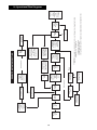
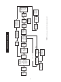
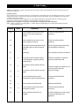
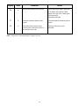
1
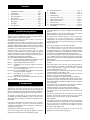
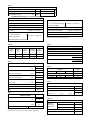
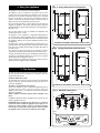
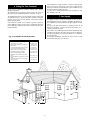
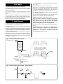
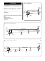
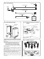
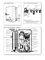
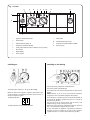
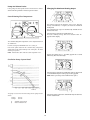
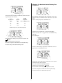
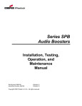
GREENSTAR
WALL MOUNTED CONDENSING BOILER FOR CENTRAL HEATING
AND MAINS FED DOMESTIC HOT WATER
INSTALLATION AND
SERVICING INSTRUCTIONS
Cat II 2H 3P appliance
GC NUMBERS
Greenstar ZWBR 7-25 A23 (N.G.) 47 311 44
Greenstar ZWBR 11-25 A31 (L.P.G.) 47 311 45
THIS APPLIANCE IS FOR USE ON SEALED PRIMARY SYSTEMS ONLY
IMPORTANT: THESE INSTRUCTIONS APPLY IN THE UK ONLY
THESE INSTRUCTIONS ARE TO BE LEFT WITH THE USER OR AT THE GAS METER
This appliance must be installed by a competent person in accordance
with the Gas Safety (Installation and Use) Regulations 1998
Contents
1.
2.
3.
4.
5.
6.
7.
8.
9.
Installation Regulations .............................................. Page
Introduction.................................................................. Page
Technical Data .............................................................. Page
Siting the Appliance .................................................... Page
Flue Systems ................................................................ Page
Siting the Flue Terminal .............................................. Page
Gas Supply.................................................................... Page
Air Supply .................................................................... Page
Sealed System .............................................................. Page
10.
11.
12.
13.
14.
15.
16.
17.
18.
19.
2
2
3
5
5
6
6
7
7
Domestic Hot Water .................................................... Page 8
Electrical........................................................................ Page 8
Installation .................................................................... Page 10
Commissioning ............................................................ Page 15
Instructions to the User .............................................. Page 21
Inspection and Servicing ............................................ Page 21
Replacement of Parts .................................................. Page 24
Short Parts List ............................................................ Page 29
Operational Flow Diagrams........................................ Page 30
Fault Finding ................................................................ Page 32
A standard 100mm flue system is available for horizontal flues
upto 2m.
Multi-directional flue systems are available up to 10m vertical
and 8m horizontal. A twin-pipe system is available.
1. Installation Regulations
Gas Safety (Installation & Use) Regulations 1998: All gas
appliances must be installed by a competent person. Failure to
install correctly could lead to prosecution.
The manufacturers notes must not be taken, in any way, as
overriding statutory obligations.
The appliance must be installed in accordance with the current
IEE Wiring Regulations, local Building Regulations, Building
Standards (Scotland) (Consolidation), bye-laws of the local Water
Company, Health and Safety Document 635 (Electricity at Work
Regulations 1989) and any other local requirements.
Product Liability regulations indicate that, in certain
circumstances, the installer can be held responsible, not only for
mistakes on his part but also for damage resulting from the use
of faulty materials. We advise the installer to avoid any risk by
using only quality approved branded fittings.
The relevant British Standards should be followed i.e.
BS 6798 Specification for the installation of gas fired hot water
boilers of rated input not exceeding 60kW
BS 5449 Central Heating for Domestic Premises
BS 5546 Installation of gas hot water supplies for domestic
purposes
BS 5440:1 Flues and ventilation for gas appliances of rated input
not exceeding 60kW: Flues
BS 5440:2 Flues and ventilation for gas appliances of rated input
not exceeding 60kW: Air Supply
BS 6891 Installation of low pressure gas pipework
installations up to 28mm (R1).
BS 7074:1 Code of practice for domestic heating and hot water
supply.
These instructions must be followed.
An integral facia display shows the central heating flow
temperature or a fault condition of the appliance.
Comprehensive safety features are standard as is an automatic
ignition system. The use of a pre-mixed burner gives a very low
NOx discharge level.
Do not run the appliance in the waterless condition.
The condensing mode gives very high efficiency figures which
can be utilised fully by sizing the system to match the
condensing parameters i.e. low temperature radiators. However
the appliance will operate at normal flow temperatures when
required to do so and still maintain high system efficiencies.
To ensure that the appliance gives the best performance possible
it is recommended that an outside temperature compensator
(Junkers TA211E) and a twin-channel digital programmer (Junkers
EU2D) are fitted.
Full installation and operating instructions are packed with the
controls.
Check that no dirt is left in either the gas or water pipework as
this could damage the appliance. Thoroughly flush the heating
system and mains water supply in accordance with the
recommendations of BS 7593:1992.
The heat exchanger is manufactured from aluminium and only
compatible flushing agents shall be used.
A link is provided to allow flushing of the system before the
appliance is hung on the mounting manifold.
Purge the gas supply before finally connecting the appliance.
To ensure that the installation will perform to the highest
standards, the system and components should conform to any
other relevant British Standards in addition to those mentioned
in the instructions.
The boiler, when in use, will operate at high efficiency emitting a
white plume of condensation from the flue terminal.
Positions that might cause a nuisance should be avoided.
A condensate drain and syphon is provided on the appliance.
Take special note of the requirements for the drainage of
condensate.
2. Introduction
The appliance output of 25.3kW in the condensing mode is
available for the heating system and up to 23.5kW for the
domestic hot water with the domestic hot water having the
priority. An automatic hot water pre-heat facility is available to
give an almost instant supply of hot water at the tap or shower.
The advice and instructions in this document covers, as far as
possible, the forseeable situations which may arise. Contact
Worcester Heat Systems for advice on specific installations.
The appliance is supplied for use on a sealed system only and is
not suitable for external installation. It must be connected to a
governed metered gas supply. It is dispatched suitable for use on
Natural Gas.
LPG Installation
The appliance shall not be installed in a room or internal space
below ground level when it is intended to be used with LPG. This
does not preclude the installation into rooms which are
basements with respect to one side of the building but open to
the ground on the opposite side.
It is a room sealed appliance and does not require a separate
combustion air supply – because of the low casing losses
ventilation are not required when the appliance is installed in a
cupboard or compartment.
Do not block the specified space left for servicing.
Asbestos or asbestos based products are not used on this
appliance nor in the manufacturing process.
An electrical supply failure will stop the appliance. Normal
operation will resume upon the restoration of the supply.
2
Fig. 1. Appliance water flow diagram.
Charging Point
Automatic
Air
Vent
Automatic
Air
Vent
Water
to
Water
Heat
Exchanger
Expansion
Vessel
Heat
Exchanger
Condensate
Trap
Pump
Drain
Pressure Relief Valve
Siphon
Diverter
Valve
Drain
Flow
Switch
CH
CH Domestic Hot Condensate & Relief Domestic
Cold Supply Return
Valve Drain
Flow Water Out
3. Technical Data
Table 1
NOMINAL BOILER RATINGS
SETTING
MAXIMUM
MINIMUM
FLOW
TEMPERATURE °C
RETURN
TEMPERATURE °C
OUTPUT
kW
INPUT
kW (Net)
GAS RATE-NG
m3/h
80
60
23.0
24.0
2.54
50
30
25.3
24.0
2.54
80
60
6.7
7.2
0.762
50
30
7.7
7.2
0.762
NOTE: Net Input = Gross Input x 0.901 - Natural Gas
Table 2
APPLIANCE DIMENSIONS, WEIGHT & CONNECTIONS
Height
Casing
850
Overall
1065-1165
mm
Width
mm
512
Depth
mm
*360
Weight
kg
Central Heating
Domestic Hot Water
Installation
74
Full
90
Inc. Packing
76
Flow/Return
22mm comp.
Inlet/Flow
15mm comp.
Gas Inlet
R3⁄4
* Wall-mounting frame depth 30mm
3
Table 3
Overall Diameter of Duct
mm
100
Flue Terminal/Duct Assembly Length
mm
600
Part No. 7 719 001 885
Extension Duct Length
mm
1000
Part No. 7 719 001 888
Max. 2m
HORIZONTAL 100mm
ALTERNATIVE HORIZONTAL 125mm FLUE SYSTEM
Overall Diameter of Duct
125mm
VERTICAL BALANCED FLUE KIT comprises:
ACCESSORIES
Extension Flue Kit 100mm
1 x 1 Flue Terminal Assembly
Part No. 7 719 001 892
Part No. 7 719 001 890
1 x Vertical Adaptor
Vertical Adaptor
90° Elbow
Part No. 7 719 001 891
ACCESSORIES
45° Elbow
Part No. 7 719 001 899
Extension Flue Kit 100mm
Part No. 7 719 001 892
125MM STANDARD FLUE KIT comprises:
90° Elbow
Part No. 7 719 001 891
1 x Flue turret Elbow
45° Elbow
Part No. 7 719 001 899
Part No. 7 719 001 890
670mm of Flue Duct
Note: The roof flashing is not supplied by Bosch.
(as measured from the centre of turret)
Table 7
Table 4
PUMP HEAD & PRIMARY FLOW
NOMINAL
TEMPERATURE
BOILER
AVAILABLE
SYSTEM
RISE ACROSS
FLOW
HEAD
FLOW
RATE
THE
SYSTEM
TEMPERATURE
m
l/min
°C
°C
BOILER
OUTPUT
kW
23.5
2
20
20
80
25.3
2
16-18
20
50
Pump Control Mode
Anti-Cycle Time
Maximum CH Temperature
ThermostatTemperature Differential
Maximum CH Output
min
°C
°C
kw
Minimum CH Output
kw
Factory Setting
2
3
80
8
23.0 standard
25.3 condensing
6.7 standard
7.7 condensing
Table 5
FLUE GAS AND CONDENSATE DATA
Flue Gas, Mass Flow
kg/h
Flue Gas Temperature
°C
Max.
38.5
Min.
11.5
Max.
71
Min.
62
Max.
36
Min.
32
Max.
2.2
Min.
0.94
Flow 80°C Return 60°C
Flue Gas Temperature
°C
Flow 50°C Return 30°C
Condensate Volume
l/h
Return 30°C
Condensate
pH
Nominal
4.1
CO2
%
Min,=Max.
9.3 - 9.7
NOx
Table 8
Total length of gas supply pipe
(metres)
3
6
9
Gas Discharge Rate (m3/h)
8.7
5.8
4.6
18.0
12.0
9.4
Pipe diameter
(mm)
22
28
Table 9.
EXPANSION VESSEL PRESSURE & SYSTEM CAPACITY
Expansion Vessel
Expansion Vessel Charge Pressure
Class 5
Table 6
litres
10
bar
0.75
System Capacity
1 bar
litres
82
Ref. BS 7074:1
1.5 bar
litres
46
CENTRAL HEATING
Heat Output
Heat Output
SEDBUK No.
80/60°C kW
50/30°C kW
Max.
23.5
Min.
6.7
Max.
25.3
Min.
7.7
BAND A
91.3
Table 10
DOMESTIC WATER PERFORMANCE
Temperature Rise
30°C
11.1
Temperature Rise
35°C
9.5
Temperature Rise
40°C
8.4
Maximum Mains Pressure
bar
8.0
Minimum Mains Pressure
bar
0.2
Domestic
Water Flow
Rate l/min
Note: To gain maximum benefit from the performance of the appliance the
radiators must be sized according to the Flow/Return temperatures.
4
Fig. 2. Casing dimensions and clearances.
4. Siting the Appliance
The appliance is not suitable for external installation.
115
No special wall protection is required. Ensure that the wall can
support the appliance. Refer to the IGE publication “Guide for
Gas Installations in Timber Framed Housing” where appropriate,
IGE/UP/7:1998.
215
▼
▼
The appliance may be installed in any room subject to the
requirements of the IEE Wiring Regulations or the electrical
provisions of the Building Regulations applicable in Scotland
relevant to appliances fitted in rooms containing baths or
showers. It must not be possible for anyone using the bath or
shower to touch any control using mains electricity.
390
512
850
60
60
The specified clearances must be available for installation and
servicing. Refer to Fig. 2 and 3.
The appliance can be installed in a cupboard/compartment to
be used for airing clothes providing that the requirements of
BS6798 and BS45440:2 are followed. The low casing losses from
the appliance eliminate the need for ventilation openings in the
compartment.
The airing space must be separated from the boiler space by a
perforated non-combustible partition. Expanded metal or rigid
wire mesh is acceptable provided that the major dimension is
less than 13mm.
The clearance between the front of the appliance and the
cupboard or compartment door should not be less than 75mm.
250
STANDARD CONCENTRIC HORIZONTAL FLUE SYSTEM
Fig.3. Casing dimensions and clearances.
115
315
▼
▼
The pipe connection positions on the manifold are shown in Fig.4
and on the wall template allowing the system to be pre-piped
and flushed before the appliance is fitted.
Always consider the possibility that the pipes may need to be
separated from the appliance after installation.
390
512
850
5. Flue Systems
60
60
The only flue systems that may be used are those sold by Bosch.
The flue system must be installed in accordance with the
requirements of BS5440:1.
Standard 100mm flue system.
The standard concentric flue system provides for a horizontal
length of upto 2m. Full instructions for fitting this flue are in
Section 12 Installation.
250
ALTERNATIVE CONCENTRIC HORIZONTAL FLUE SYSTEM
Alternative 125mm diameter flue systems.
Systems are available to give a maximum horizontal length of
8m (this system requires a greater clearance above the
appliance. Refer to Fig.3.) A vertical flue system upto a height of
10 metres is available.
NOTE: A 100mm vertical flue systems will be available in the
future.
Fig. 4. Manifold connections.
▲
▲
▲
▲
200
20
10
▲
30
Installation instructions for the alternative flue systems are sent
with the appropriate flue kit.
▲
▲
▲
▲
▲
Gas
65
Cold
water
inlet
Valve
clips
Wall mounting manifold plate
5
65
▲
65
Domestic
hot
water
▲
65
▲
Central
heating
flow
▲
IMPORTANT: The horizontal flue system fitted to a condensing
boiler must incline towards the appliance at an angle of 21/2°
(44mm per metre length) to prevent condensate dripping
from the flue terminal. This means that the clearance above
the appliance must be increased to match the duct length.
Central
heating
return
If the terminal is less than 2m above a surface to which people
have access then a guard must be fitted. The guard must be
evenly spaced about the terminal with a space of 50mm in each
direction and fixed with plated screws.
A guard, can be obtained from Tower Flue Components, Vale
Rise, Tonbridge TN9 1TB.
6. Siting the Flue Terminal
The flue must be installed in accordance with BS 5440:1 and the
Building Regulations.
The terminal must be positioned so that it does not cause an
obstruction or the combustion products a nuisance. See Fig.5.
The terminal will, at times, give out a plume of water vapour and
consideration must be given to this when choosing a terminal
position. Keep clear of security lighting, activated by passive
infra-red sensing heads.
7. Gas Supply
The appliance requires 2.54m3/h of natural gas. The gas meter
and supply pipes must be capable of supplying this quantity of
gas in addition to the demand from any other appliances being
served.
The meter governor should deliver a dynamic pressure of 20
mbar at the appliance, equivalent to a pressure of about 18.5 –
19mbar at the gas valve inlet.
Where LPG is used, following conversion from Natural Gas, then
a dynamic inlet pressure of 37mbar at the inlet to the appliance
is required. Equivalent to a pressure of about 34.5 – 35mbar at
the gas valve inlet.
The complete installation, including the meter, must be tested
for soundness and purged. See BS 6891.
If the terminal is within 1m of a plastic or painted gutter or
within 500mm of painted eaves then an aluminium shield at
least 750mm long should be fitted to the underside of the gutter
or painted surface.
Fig. 5. Acceptable terminal positions.
TERMINAL POSITION
MIN. DISTANCE
A– Directly below an openable window or
other opening e.g. air brick.
B– Below gutters, soil pipes or drain pipes.
C– Below eaves.
E– From vertical drain pipes and soil pipes.
F– From internal or external corners.
G– Above ground, roof or balcony level.
H– From a surface facing a terminal.
I– From a terminal facing a terminal
K– Vertically from a terminal on the same
wall.
L– Horizontally from a terminal on the same
wall.
M– From door, window or air vent (achieve
where possible).
300 mm (12 in.)
75 mm (3 in.)
200 mm (8 in.)
75 mm (3 in.)
300 mm (12 in.)
300 mm (12 in.)
600 mm (24 in.)
1200 mm (47 in.)
1500 mm (59 in.)
300 mm (12 in.)
150 mm (6 in.)
A
L
G
B,C
K
L
D
K
F
F
HI
A
F
J
E
G
M
6
The filling point must be at low level and arranged as shown in
Figs. 6 and 7
8. Air Supply
The pressure relief valve is set to operate at 3 bar.
A separate air supply for combustion is not required.
If the appliance is in a cupboard or compartment then, because
of the low casing losses, it is not necessary to have additional
ventilation for the boiler.
There must be no connection to the mains without the approval
of the local water company. All connections in the system must
be capable of withstanding a pressure of up to 3 bar and the
radiator valves conform to the requirements of BS 2767:10.
The specified clearances around the appliance must be
maintained to allow the free movement of the air. Refer to
Fig.2,3.
If Thermostatic Radiator Valves are fitted then it is recommended
that one radiator is left open.
Repeated venting probably indicates a leak and this must be
rectified to ensure the proper operation of the appliance.
Note: In order to prevent corrosion the air for combustion must not
contain corrosive substances such as solvents, paints, adhesives,
household cleaners etc. The combustion air should be dust free to
reduce the risk of the pre-mix burner becoming blocked.
No galvanised radiators or pipes must be used.
If any system water treatment is required then only Sentinal
X100 shall be used, in accordance with the manufacturers
instructions. The use of any other substances will invalidate
the guarantee. The pH value of the system water must be less
than 8 or the appliance guarantee will be invalidated.
9. Sealed Systems
The appliance must not be operated without the system being
full of water, properly vented and pressurised.
A drain cock to BS2879 must be fitted to the lowest point of the
system.
The expansion vessel has a volume of 10 litres and is charged to
a pressure of 0.75 bar.
The water capacity of the system is shown in Table 9. If a greater
capacity is required then an additional expansion vessel must be
fitted into the system return as close to the appliance as possible.
The system pressure can be set up to a maximum of 1.5 bar with
1 bar being the normal setting.
If the system pressure is greater than 2.5bar when the appliance
is operating at maximum temperature then an additional
expansion vessel must be fitted into the system return as close
to the appliance as possible.
IMPORTANT: Check that no dirt is left in the water pipework
as this could damage the appliance. Thoroughly flush the
heating system and the mains water supply before fitting the
appliance to the wall in accordance with the
recommendations of BS7593:1992.
Fig. 6. Sealed primary water system.
Automaticl air vent
APPLIANCE
Refer to Fig.1
Appliance
water flow
diagram
A drain cock should be fitted at
the lowest point of the heating
circuit and the appliance
WRC approved
filling loop
Lockshield
valve
Central heating return
Domestic
hot water
Domestic
hot water
Central heating flow
Radiator
valve
BS stop valve.
Fixed spindle type
Water
main
Fig. 7. Sealed primary water system – filling method.
Heating
return
Non-return
valve
Non-return
valve
Hose
union
Hose
union
Test
cock
Test
cock
Temporary hose
7
10. Domestic Hot Water
11. Electrical
Any regulations specified by the local water company must be
observed.
Supply: 230V ~ 50Hz 140 watts. External fuse 3A. Protection
IPX4D.
Mains cable: PVC insulated 0.75mm 2 (24 x 0.20mm) to
BS 6500–Table 6. Temperature rated 100°C.
The final 600mm of the mains cold water connection to the
appliance should be made in copper tube only.
It must be possible to isolate the appliance
The appliance must be earthed.
The appliance is suitable for a mains supply having a maximum
pressure of 8 bar. A pressure reducing valve must be fitted, if
necessary.
The appliance must be connected to the mains through a 6A
double pole isolator with a contact separation 3mm in all poles
and supplying the appliance and controls only. The wiring must
comply with the current requirements of the IEE Wiring
Regulations and any local regulations which apply.
The hot water outlet temperature is set to be capable of
operating between 40 - 60°C. When operating normally the
boiler operates occasionally to maintain an 8 litre heat store at
this temperature ensuring that hot water is available at the tap
or shower almost immediately it is required. The maximum
temperature and the frequency of the recharge of the heat store
may be reset.
To gain access to the mains connection remove the drop down
facia cover. The drop down cover is removed by lowering it to the
horizontal position and pushing firmly upwards at the rear of
the supports to release the cover. Lift cover from the appliance.
Remove the facia connection cover. Refer to Fig.
The maximum water flow rate is factory set at 9.5l/min to give
temperature rise of 35°C. If a higher rise is required then the flow
must be reduced at the tap and the discharge temperature will
rise up to the maximum set figure.
After installation (or in the event of an electrical fault) the electrical
system shall be checked for short circuits, fuse failure, incorrect
polarity of connections, earth continuity and resistance to earth.
The temperature rise, upto the maximum set by the user, is
automatically maintained by the modulation of the heat input.
In winter, when the mains temperature is very low, the water
flow, adjusted at the tap or shower, should be reduced to
maintain the required delivery temperature.
It is suggested that long pipe runs to taps or showers be
insulated to prevent the rapid cooling of the water.
All types of single lever mixer taps and thermostatic mixer units
suitable for a mains pressure of up to 8 bar can be used.
The head of a loose-head shower must not be allowed to fall
within 25mm of the top the bath to prevent the risk of water
being drawn back into the mains. Alternatively the shower must
be fitted with an anti-syphonage device at the point of the
flexible hose connections.
Over-rim bidets may be connected to the appliance provided
that it is in accordance with the requirements of the local water
company. The outlet(s) should be shrouded and unable to have
any temporary hand held spray attached. No anti-syphonage
arrangements are necessary.
In exceptionally hard water areas a device to prevent scale
formation may be fitted or, alternatively, the maximum
temperature reset to about 45°C which may reduce the risk of
scale formation. The installation of a scale inhibitor assembly
should be in accordance with the requirements of the local water
company. Artificially softened water must not be used. An
isolating valve should be fitted to allow for servicing.
Devices capable of preventing the flow of expansion water must
not be fitted unless separate arrangements have been made.
A Zilmet Z160 expansion vessel is the preferred type. A thread
sealant compatible with potable water must be used.
8
Fig. 8. Pictorial wiring diagram.
o - orange g - green
bl - black
21
o
bl
27
25
o
28
29
30
g
g
g
g
o
bl
22
p - purple
26
24
20
r - red
31
r
23
r
r
o
bl
bl bl
p
bl bl
13
11
14
12
19
15
17
16
18
25V
8
230V
AC
9
10
3
7
4
328
1
2
5
6
Fan
Module
Mains
Input
Pump
Fan
1
2
3
4
5
6
7
8
9
10
11
12
13
14
15
16
17
18
19
Fuse 2.5A, 230V AC
Fuse 0.5A
Fuse 1.6A
Control unit connection
Key Plug
TA 211E control connection
Time switch connection
On/off switch
CH temperature
DHW temperature control
Power on indicator
Ignition transformer
Ignition electrodes
Setting button
Reset button
Display
Service button
ECO button
Burner indicator
20
21
22
23
24
25
26
27
28
29
30
31
9
DHW temperature sensor
Water pressure switch (flow switch)
DHW inlet sensor
Air flow switch
CH flow temperature sensor
Flame sense electrode
Gas valve
Gas solenoid valve No.1
Gas solenoid valve No.2
Flue gas temperature limiter
Overheat temperature limiter
Diverter valve solenoid
p
Fig. F1. Standard Flue.
12. Installation
The standard 100mm diameter horizontal flue system is suitable
for lengths upto 2m.
Flues upto 670mm do not require an extension duct assembly.
Terminal
Assembly
Flues between 670mm 1620mm require 1 extension duct
assembly.
Flue
Turret
Flues between 1620mm and 2000mm require 2 extension duct
assemblies.
Maximum 670mm
Flue
Sample
Point
NOTE: Flue lengths between 670mm and 730mm cannot be
accomodated.
Outer
Wall
Refer to Fig.F1,F2 and F3.
Standard system comprise:
Flue turret _ Flue turret clamp _ Terminal assembly _ Wall sealing
plates.
No
Clamp
Clamp
Extension kit comprises:
Air duct _ Flue duct _ Duct clamp.
Refer to Fig.F4.
Fig. F2. Flue with One Extension .
Terminal
Assembly
Flue
Turret
Maximum 1620mm
Flue
Sample
Point
Clamp
No
Clamp
Clamp
Outer
Wall
Extension
Duct
Fig. F3. Flue with Two Extensions .
Terminal
Assembly
Flue
Turret
Maximum 2000mm
Flue
Sample
Point
Clamp
No
Clamp
Clamp
Clamp
Extension
Duct
Extension
Duct
10
Outer
Wall
Fig. F4. Flue Components.
Duct Clamp
Flue
Turret
Extension Air Duct
Turret
Clamp
Extension Flue Duct
Terminal Assembly
Fig. 10. Marking the position of the side flue
opening.
Fig. 9. Wall mounting assembly.
Support
Lugs
Wall Sealing Plates
Wall Mounting
Plate
Drilling point for
flue duct opening
Centre line of
flue/air duct
H
Centre
line of
flue
opening
and
appliance
Top of the
wall
mounting
frame
(or 85mm
if wallmounting
frame not
used)
Appliance
Manifold
Assembly
Standard Horizontal Flue
Alternative Horizontal Flue
The fitting of this flue system is described later in the installation
process.
Instructions for fitting other flue systems are packed with the
relevant flue kit.
NOTE: The 125mm diameter horizontal flue system to be
used for lengths between 2m and 8m requires a
clearance of 365mm above the appliance casing to
accomodate the rise in the flue over the full length.
2.5¡
(44mm/meter)
1 in 22
115
H mm
88
120
Fig. 11. Manifold connections.
▲
▲
▲
▲
200
20
10
▲
30
▲
▲
▲
▲
▲
Gas
65
Cold
water
inlet
Valve
clips
NOTE: The wall-mounting assembly is not absolutely
necessary if a side flue is to be fitted. The wall to flue centreline dimension will reduce to 85mm. Refer to Fig. 10.
Fix the wall mounting assembly together using the screws
supplied to secure the top and bottom cross-members. Refer to
Fig.9.
Ensure that the top section has the support lugs facing upwards
and outwards.
Wall mounting manifold plate
11
65
▲
65
Domestic
hot
water
▲
65
▲
Central
heating
flow
A wall mounting plate and manifold assembly are supplied in a
separate pack to allow the pre-installation connection to the
system and flushing.
▲
Check that the position chosen for the appliance is satisfactory.
Unpack the appliance.
Central
heating
return
Fig. 13. Condensate discharge system.
Fig.12. Removal of casing
Syphon
Casing
Syphon
Drain
Pipe
Security
Screw
(partially
unscrew)
Drain
NOTE We should state that:
Altough the Tundish is supplied, it may be more
suitable to connect directly to the 3/4 " connection on
the syphon with the plastic pipe supplied.
Casing
Clip (2)
Fig. 14. Inner Casing Controls / Components.
Cap
Manifold Assembly
Fan Assembly
Cap
Fan Assembly
Fixing Screws (2)
Automatc Air Vent
(Expansion Vessel)
Burner Assembly
Automatic Air Vent
(Heat Exchanger)
Burner Assembly
Front Fixings
Expansion Vessel
Flame Sense
Electrode
DHW Heat Exchanger
(to rear)
Observation
Window
Gas/Air Mixing
Tube
Spark Electrode
CH Flow Sensor
(Orange Leads)
Gas Control
Module
Overheat Thermostat
(Red Leads)
Fixing Screw
Expansion Vessel
Fixing Screws (2)
Heat Exchanger
CH Return
Air Flow Switch
Expansion Vessel
Connection
Heat Exchanger
Fixing Bracket
Flue Temperature Thermostat (Red Leads)
12
Fig. 15. Lower Controls / Components.
CERAPUR:
Diagram 10b
26/3/99
Inner Casing
Gas Valve
Manual Air Vent
and Siphon Fill
Gas Valve Inlet
Pressure Test
Point
Pump
Pump Cap
2
1
3
Pressure Guage
4
Syphon
Boiler Drain Plug
Fixing Screw
Fixing Screw
Diverter Valve
Facia
Fixing Screw
Using the template or the wall mounting plate mark the
positions of the fixing holes and the position of the rear, if
applicable, flue.
Drill, plug and fix the wall mounting plate to the wall. Fix the
manifold assembly to the wall mounting plate. Refer to Fig.9.
Fig. 16. Access cover and electrical connections.
4
5
3
4
Mark the position of the flue opening if a side flue is to be used.
Refer to Fig.10.
The manifold assembly is supplied assembled with the water
valves in the positions shown in Fig.11 and fixed with the clips
provided. Fix a connection to the gas cock. Refit the gas cock
and clip, secure in position with the screwed clamp.
I
0
Drill a hole 180mm diameter through the wall for the rear or
side flue assembly.
NOTE: The flue system must incline 21/2°
(44mm/metre length) towards the appliance to
prevent condensate dripping from the flue terminal.
The diameter of the hole required for the alternative
flue system can be found in the instructions sent with
the flue kit.
1
7
7
Gently pull clip-on cover at
base and lift off appliance.
Unscrew connections cover
and slide forwards to remove.
Mains Connection
Heater Control Unit
Connection
L
The heating system and the domestic water pipes can now be
connected if not already done so. Do not fix the pipes rigidly to
the wall as some movement of them must be retained. A flexible
link is provided to allow the flushing of the system.
NOTE: The domestic water inlet and delivery valves are not
positively fixed. When tightening connections ensure that the
shut-off control faces forward.
1
0
E
2
I
E
2
5
3
N NsLs LR
Fuse
2.4A 230Vac
+
DC24V
1 2 4 7 8 9
1
2
4
Fix a WRc approved filling loop in the central heating return as
close as possible to the appliance.
Connect the gas supply pipe to the appliance.
1
Condensate Discharge
Fix the condensate discharge system. See Fig.13. A tundish
condensate and relief valve drain fitting is provided. Refer to the
Building Regulations and the CIBSE Guidelines, where
applicable, for details of the allowable condition of condensate
discharge.
2
4
1 2 3 4
Use flat bladed
screwdriver
13
TR...
A condensate neutralisation kit is available.
The condensate drain pipe and fittings must be made of plastic
(NO OTHER MATERIALS SHALL BE USED) with a minimum
diameter of 22mm.
Mark off the lengths shown onto the ducts and cut to length. The
cuts must be square and free from burrs.
Terminal assembly outer (air) duct - L-70mm
inner (flue) duct - L-50mm
the measurement is made from the ridge at the terminal
indicating the outer face of the wall. Refer to Fig.F7.
Extension air duct - L-70mm
flue duct - L-50mm
The measurement is from the formed end.
The minimum fall for the drain pipe from the open tundish is
2.5° (1 in 20). Where it is not practical to terminate a condensate
drain over a gully then an additional trap should be provided
prior to any connection to a soil and vent pipe (discharge pipe) or
waste pipe (branch discharge pipe).
Any connection to a waste pipe should be downstream of the
appliance trap to prevent any household waste blocking the
condensate drain or causing back flow or back pressure on the
appliance.
Fig. F7. Flue terminal position
Outer
Wall
Face
Remove the security screw from the right-hand side of the
casing. Refer to Fig.12
Flue Terminal
Remove the cabinet by pressing both levers backwards to release
and lift off the cabinet. See Fig.12.
Hang the appliance onto the wall.
Fit the fibre washers to the gas and water connections on the
manifold.
Raised Ring
locating the
terminal relative
to the outside
wall face
Tighten the service connections.
Flue duct preperation and assembly
Measure the flue length L. Refer to Fig. F5 and F6.
Assemble flue system completely. Push the ducts fully together
and clamp in the positions shown in Fig. 2 and 3. The slope of
the terminal outlet must face downwards.
The assembly will be made easier if a solvent free grease is
lightly applied i.e. Vaseline, to the male end of the ducts.
NOTE: An inner wall sealing plate is provided which should
be fitted to ducts before assembly.
Push the assembly through the wall and fix the turret to the
appliance with the clamp. Refer to Fig.F8.
Fig. F5. Flue lenth rear
L
Fig. F8. Flue turret
85
Flue Turret
30 (Wall Frame)
NOTE: THE FLUE MUST BE INCLINED TO THE
BOILER
Clamp
Fig. F6. Flue lenth side
Air and
Flue Duct
Entry into
silicone
rubber seals
L
Flue Socket
on Boiler
Ensure that the turret is fully entered into the socket on the
boiler. From outside fix the outer wall plate to the terminal and,
after ensuring the duct is properly enclined towards the boiler, fix
the plate to the wall.
If the terminal is within 2m of the ground where there is access
then an approved terminal guard must be fitted. The guard must
give a clearance of at least 50mm around the terminal and be
fixed with corrosion resistant screws.
NOTE: THE FLUE MUST BE INCLINED TO THE
BOILER
14
Connect a drain to the relief valve outlet ensuring that it does not
discharge onto electric components or where it might be a
hazzard. The pipe must be not less than 15mm in diameter.
Open the heating system valves on the manifold and all the
radiator valves. Fill the system through the WRc approved filing
connection to a pressure of about 1.5 bar and check for water
soundness. Refer to Fig.6 and 7. The automatic air vents on the
appliance will remove air from the appliance but each radiator
must be vented separately. The manual air vent must be open to
allow the venting of the appliance. Tighten the screw when
venting is complete. Refer to Fig.15.
Make the electrical connections to the appliance through the
cable clamps in the base of the appliance.
Remove the drop-down facia cover by lowering it to the
horizontal position and pushing firmly upwards at the rear
supports to release the cover. Lift the cover from the appliance.
Remove the clipped on-cover and unscrew the inner cover to
expose the connectors. Refer to Fig.16.
Fill the condensate trap by opening the manual air vent/siphon
fill connection until water is discharged showing that the siphon
is full. Refer to Fig.15.
Remove the automatic air vent cap. See Fig. 14.
Check that all the gas and water connections on the manifold are
tight.
Check that the pressure relief valve operates by, after removing
the cap, turning the knob anti-clockwise until it releases and
water is expelled from the discharge pipe. The relief valve is
located beneath and behind the pump at the right-hand side.
Final Installation.
Replace the cabinet front panel.
Refer to Section 13 Commissioning, for a full discription of the
filling, venting and pressurisation of the system.
Remove the plated cap from the pump and turn the shaft about
half a turn using a flat blade screwdriver. Replace the cap. Refer
to Fig.15.
If the appliance is not to be commissioned immediately then
check that the gas supply, the electrical supply and all the water
connections are turned off.
Set the system pressure to 1bar by releasing water from the relief
valve and, if necessary, the expansion vessel pressure.
The 10 L expansion vessel, supplied with a charge pressure of
0.75 bar (static head 7.5 metres), must not be at a pressure less
than the static head of the system. A schraeider type valve is
provided on top of the vessel if it is necessary to increase the
charge pressure.
Refer to BS7074:1 and Table 9 for details of the allowable system
capacity.
If the system volume is greater than that which can be
accomodated by the expansion vessel on the appliance then an
extra vessel must be fitted as close to the appliance as possible
in the central heating return. It must be charged to the same
pressure as the vessel in the appliance.
If the premises are to be left unoccupied in very frosty conditions
then drain any water from the appliance and the system
Test the gas supply for soundness as described in BS 6891.
If the appliance is not to be commissioned immediately replace
the cabinet. Turn off the gas, electrical and water connections.
13. Commissioning
The appliance is adjusted at the factory to give the settings
shown in table 7.
If any changes are made to these settings they must be recorded
on the commissioning label to be fixed to the appliance and in
the relevant booklet.
The domestic hot water discharge temperature and the central
heating flow temperature may be adjusted on the facia to satisfy
different conditions.
Connect a pressure gauge to the gas valve inlet pressure test
point and open the gas tap. See Fig. 19.
Set all the external system controls to on or maximum.
Set the central heating and domestic hot water control knobs to
minimum. Check that the condensate trap and syphon are full
(to prevent flue gas spillage).
The appliance must NOT be operated without the siphon
being full.
Domestic Hot Water
Confirm that the mains water supply has been flushed out at
installation. If not it will be necessary to disconnect the cold
water inlet pipe at the appliance and thoroughly flush.
The instructions following describe the operation of the
appliance.
Central Heating
Confirm that the central heating system has been fully
flushed out at installation. If not then thoroughly flush the
system using clean water if possible. Any additives must be
compatible with aluminium heat exchangers.
The system water must not have a pH greater than 8 or the
appliance guarantee will be rendered invalid. If any system water
treatment is required then only products suitable for use with
Aluminium shall be used i.e. Sentinel X100, in accordance with
the manufacturers instructions. The use of any other substances
will invalidate the guarantee.
Gas Service
The complete system, including the meter, must be inspected
and tested for soundness and purged as described in BS 6891.
Check that the gas and electrical supplies to the appliance are
turned off.
Check that any controls are in the off position.
Check that all the water connections throughout the system are
tight.
Remove the cabinet by unclipping the two clips and lifting away.
Refer to Fig.12.
Remove the automatic air vent caps. Refer to Fig.14.
15
Fig. 17. Facia.
4
5
6
7
8
9 10
11
12
3
2
1
1
Appliance identification sticker
9
'ECO' button
2
Master switch
10
Indicator lamp for burner on
3
Indicator lamp for power on
11
Temperature control for DHW on ZWRB
4
Temperature control for CH flow
12
Pressure guage
5
Setting button (also refered to as 'Chimney Sweep' button)
6
Reset button
7
Digital display
8
Service button
Switching on
Switching on the Heating
Turn on the heating temperature control knob to E.
The burner and the red LED will light.
Turn on the power switch to 'I'. The green LED will light.
The temperature of the water leaving the boiler is shown on the
display.
NOTE: Position 'E' can be set as the maximum adjustable
temperature. Refer to 'Central Heating Flow Temperature'.
NOTE: The first time the appliance operates (and whenever the
electricity supply is re-established) it will run at low rate for 15
minutes to check the siphon.
There should be a dynamic pressure of 20 mb (Natural Gas) at
the inlet to the appliance equivalent to about 18.5-19.0 mb at
the inlet to the gas valve.
Run the system in the heating mode and check that each
radiator heats up evenly, venting as necessary.
Balance the system to achieve a differential across the system of
20°c. An external system bypass may be needed.
The display will show
The boiler will then revert to normal operation.
If, after conversion, the appliance is operating on LPG then a
dynamic pressure of 37mbar at the inlet to the appliance
equivalent to aout 34.5-35mbar at the inlet to the gas valve.
16
Domestic Hot Water Temperature Control
Lock-Out Mode
Turn the control knob to set the discharge temperature between
40°C (Min) and 60°C (Max) - this temperature does not appear
on the display.
If a lock-out occurs the reset button lights and the display shows
a fault code.
Press the reset button to restart the appliance (flow temperature
appears on the display).
Open a tap and check that the hot water is available in a few
seconds. Close the tap.
If the fault persists refer to Section 18 Fault Finding and call a
Service Engineer.
NOTE: It is recommended that the discharge temperature does
not exceed 45°C where OAP's and children are to have access.
A Thermostatic mixing valve may be fitted outside the
appliance.
Switching Off
Domestic Hot Water Only (Summer Operation)
Turn the Power Switch to '0'. The green LED goes out.
Any time switch fitted will continue until the internal power
source runs out.
Turn the heating temperature control knob fully anti-clockwise.
The heating function is turned off but the control unit remains
live for the dhw function.
Frost Protection
Short Periods
The heating system should be left on with the
temperature control knob at, at least, setting 1.
Long Periods
If the appliance is not to be operated for long periods of
freezing weather then the power should be turned off and
the appliance and system drained.
Full frost protection of the appliance and system is provided
with the fitting of the outside temperature controller and control
unit.
17
Pump Anti-Seizure Device
Changing the Maximum Heating Output
If the pump has not operated for 24 hours then it will be
switched on for a period of 5 minutes to prevent seizure.
Central Heating Flow Temperature
The heating output of the appliance can be reset, from the
factory set maximum, if required, to match the maximum
heating load.
The maximum heat output is automatically available for the
domestic hot water.
Turn the heating temperature control knob to 'E'
Press the 'chimney sweep' and service buttons until ' = '
appears on this display.
The central heating flow temperature can be adjusted between
35°C and 88°C.
It can be set to give a maximum of 75°C i.e setting 'E'.
Prise off the yellow button on the central heating temperature
control and turn the button through 180° and replace. The knob
will not go beyond 'E'.
NOTE: This should be done with the button at position 4 or 5.
Release the buttons and '9.6', or similar, appears for 5 seconds
followed by '00'. The buttons light.
Circulation Pump/System Head
Turn the heating temperature control knob until '5.0' appears for
5 seconds followed by the heating output setting appears.
NOTE: This is a percentage of the maximum rate upto 99.
Lt min Q
The pump is set to one of the two settings on the pump selector
switch.
Setting 1
Setting 2
H
Q
Turn the hot water temperature control knob fully anti-clockwise
until the buttons flash.
Curve C
Curve B
Available system head
Water circulation rate
18
Changing the Maximum Central Heating Flow
Temperature
Turn the hot water temperature control knob clockwise until the
required output level is reached.
Central
Display
Heat
Heating
Output Level
Input kw
Output kw
(MAX)
(NET)
( Non-condensing Mode)
99
24
23
85
20.6
19.6
65
15.8
15
55
13.5
12.7
The maximum central heating flow temperature can be reset
from the factory set maximum of 88°C to between 35°C and
88°C .
Turn the heating temperature control knob to 'E'.
NOTE: Net Input = 0.901 x Gross Input (NG)
--
Press the 'service ' button until ' ' appears on the display.
Release the button and '4.6' appears for 5 seconds followed by
'00' or '01' .
The button lights.
Press and hold the 'chimney sweep' and service buttons until
'
' appears.
The reset heating output is now stored.
Return the temperature control knobs to the original settings.
Record the change in the Commissioning Record.
Turn the central heating temperature control knob until '2.5'
appears for 5 seconds followed by '88'.
Turn the hot water temperature control knob to the required
maximum heating flow temperature.
The 'service' button and the display will flash.
Press the 'service' button until '
' appears.
The maximum central heating flow temperature is stored.
Return the temperature control knobs to the original settings.
Record the change in the Commissioning Record.
19
Changing the Control Mode for Heating
Operation
NOTE: This controls the operation of the pump-it does not
change the pump speed.
The factory setting is 2 for the boiler to operate with a room
thermostat fitted.
It is not necessary to change the setting if an outside
temperature compensator is fitted. The control will
automatically adjust to Mode 3.
Turn the central heating temperature control anti-clockwise until
2.2 appears - after 5 seconds the mode setting of 2 (factory
setting) appears.
Control Mode 1
Not recommended.
No room thermostat or outside temperature
control.
Pump switched by central heating flow
temperature.
Factory Setting
Control Mode 2
Room thermostat fitted.
Central heating flow temperature switches
the gas, the pump continues to run.
The room thermostat switches the gas and
the pump.
The pump and fan have overun times of
between 15 sec and 3 min.
Turn the domestic hot water temperature control knob until
mode setting 3 appears.
Control Mode 3
Outside temperature compensator fitted.
The outside temperature compensator
switches the pump.
In Summer mode, the pump runs for the
domestic hot water only.
The 'service' light will flash.
Press the 'service' button untill '
' appears.
The new control mode setting is stored and the ceral heating
flow temperature is displayed.
Turn the central heating temperature control knob to 'E'.
Press the 'service' button until ' ' appears on the display.
--
Reset the central heating and domestic water control knobs to
the user requirements.
Record the change in the Commissioning Record.
Anti-Cycle Time
This is Factory Set at 3-min.
It is not recommended that this is changed.
Switching Difference
Release the button - '4.6' will appear for 5 seconds followed by
'0.0' or '0.1'
This is Factory Set DHW at 8°
CH at 5°
The 'service' button will light.
It is not recommended that this is changed.
20
14. Instructions For The User
Completion of Commissioning
Note: Operating with a lower heating flow temperature will
result in the appliance operating in the much more efficient
condensing mode. To ensure that the rooms are properly heated
the radiators must be sized accordingly.
Instruct the user in the efficient and safe operation of the
appliance and hand over the user’s leaflet.
Describe the operation and function of the controls. Set the
appliance and external controls to the user’s requirements.
Switch off the appliance.
Disconnect the pressure gauge at the gas valve and tighten the
test point screw. Check for gas soundness around the screw. See
Fig. 18.
Show the user how to vent the radiators.
Tell the user of the system pressure which must be maintained.
Tell the user what to do if the appliance is not to be used in frosty
conditions.
Refit the front cabinet.
If the appliance is to be passed over to the user immediately
then refer to Section 14.
Advise the user of the importance of regular (annual) servicing to
maintain the efficiency and extend the life of the appliance.
Worcester Heat Systems will be pleased to offer a service
contract.
If there is any possibility of the appliance being left inoperative
for very long periods in very frosty weather then drain the
appliance and the system. Turn off the gas and electricity
supplies.
15. Inspection and Servicing
Fig. 18. Gas valve.
It is the law that any service work is carried-out by competent
engineers such as British Gas or CORGI registered engineers.
Pre-Service Inspection
Check that the flue terminal (and terminal guard) are clear and
undamaged.
Seal
Locknut
If the appliance is in a cupboard/compartment check that the
specified service spaces are clear. Refer to Fig.2 and 3.
Inner Case
Base
Check the connections in the system and remake any which
show signs of leakage. Refill, vent and repressurise the system
after this work. Do not forget to refill the condensate trap and
syphon.
Air
Distributor
Gas Valve
Solenoids
Operate the appliance and system and take note of any action
which needs to be taken.
NOTE: If the mains elecricity is turned off then the siphon
check procedure will take place when it is re-established.
Refer to Section 13 Commissioning.
Gas
Valve
To disable the siphon check procedure follow the following
instructions.
Seal
Inlet Pressure
Test Point
The siphon check programme will run automatically if:
a)
Power is applied or re-applied to the boiler.
b)
The boiler has not run for a period of 48 hours.
c)
At a change from Summer to Winter operation and
vice versa.
The siphon check is operating when there is
on the display.
The check comprises operation for 15 minutes at minimum rate.
To Disable the Siphon Check:
1. Set the CH temperature control to E. Refer to Fig.S1.
Fig. S1..
2. Press the Setting and Service buttons and hold until
appears on the display. Refer to Fig.S1.
21
3. After 5 seconds a figure wil appear on the display followed by
0.0 and the flashing of the buttons. Refer to Fig.S2.
Fig. S4..
Fig. S2..
6. To enter the change press and hold both buttons until
appears. Refer to Fig.S5.
Fig. S5..
4. Turn the CH temperature control until 8.5 appears followed
after 5 seconds, by 1. Refer to Fig.S3.
Fig. S3..
The boiler will now operate as set by controls.
IMPORTANT : The siphon check programme must be reset
after the service has been completed i.e enter 1 into the
memory.
5. To disable the siphon check programme turn the DHW
temperature control until O appears in the display.
Refer to Fig.S4.
There is the facility to check the control settings of the appliance.
Refer to the diagram and table below.
(1)
(4)
(2)
(3)
Service Function
How to read out
Pump control mode
2.2
Anti-Cycle time
2.4
Maximum heating flow
temperature
2.5
Turn (3) until display (4) shows '2.5'.
Wait until (4) displays the
setting.
Heating temperature
switching differential
2.6
Turn (3) until display (4) shows '2.6'.
Wait until (4) displays the
setting.
Maximum heating
output
5.0
Press (2) until display (4)
shows ' '.
Wait until (4) shows '0.0' or '0.1'.
Press (1) and (2) until display (4)
shows ' '.
Wait until (4) shows '0'.
22
Turn (3) until display (4) shows '2.2'.
Wait until (4) displays the
setting.
Press (2) until display
shows '
'.
Turn (3) until display (4) shows '2.4'.
Wait until (4) displays the
setting.
Return the temperature
control knob (3) to its original
setting.
Turn (3) until display (4) shows '5.0'.
Wait until (4) displays the
setting.
Press (1) and (2) until display
shows '
'.
Fig.19 . Burner body.
Fan Assembly
Fan Connector
Fan Assembly
Fixing Screws
Burner Body
Fixing Screw
Burner Body
Split
Pin
Burner Body
Fixing
Mixing Tube
Spark
Electrode
Assembly
Air Flow Tube
Sight Glass
Gas
Flame Sense
Electrode
Remove the cabinet . Refer to Fig. 12.
Check that the condensate trap and syphon are clear and clean,
if necessary, by draining and refilling. Remove the yellow cap at
the base of the siphon to drain. See Fig. 30.
Fig. 20. Burner plate position.
Ensure that the system is full, vented and pressurised.
Check the inlet gas pressure and the maximum heat input. Refer
to Table 1 and Section 7. If the gas rate has dropped by more
than 5% from the specified figure then check the combustion
performance of the appliance.
Connect a combustion test meter (to read CO2 %)to the test point
on the flue turret and operate the appliance at maximum input
for 10 minutes. See Section 11. A CO2 reading of about 9.5±
0.2% should be achieved.
If the figures for the gas rate and the CO2 are not satisfactory
then it will be necessary for the appliance flueways to be
cleaned.
Turn off the gas and electricity supplies. Remove the inner casing
cover. Release the fan assembly by unscrewing the two extended
screws. Unscrew the rear fixing screw, remove the split pins and
unscrew and remove the front fixings. Remove burner casing. Lift
out the burner skin and seal. Refer to Fig.20.
Lightly brush the exposed flueways.
Remove the yellow siphon trap drain plug and the grey
condensate drain cap. Refer to Fig.31. Pour clean water through
the heat exchanger and into the condensate trap drain until the
water coming from the heat exchanger is clear.
Replace the cap and plug.
Refill the siphon.
When replacing the burner flame strip do not forget the new
gasket. Refit the fan assembly in the reverse order. Refer to
Fig.20. Tighten the nuts evenly by hand plus sufficient extra
force to allow the fitting of new split pins. Tighten the rear
fixing - do not over tighten.
Front of Appliance
Heat Exchanger
Body
seal
7mm
Burner Flame
Strip
23
Brush any dust from the controls using a soft non-metallic brush
and battery operated vacuum cleaner.
Fig. 21. Facia connections cover.
If any parts need replacing then refer to Section 16.
Facia
On completion of the service check for gas soundness and the
correct operation of the appliance as described in Section 12.
Refit the cabinet and check that the controls are set to the user’s
requirements.
4
5
3
E
2
I
0
1
7
Lower Facia cover
(clip-on)
16. Replacement of Parts
Important: Switch off the electricity and gas supplies before
replacing any components.
After the replacement of any component check for gas
soundness, where relevant, and carry out functional checks as
described in Section 13.
4
0
Any gasket or seal which appears damaged must be replaced.
It will be necessary to drain the appliance to remove some
components.
Drain the Appliance
Check that the electrical supply to the appliance is turned off.
When the mains electricity is re-established the appliance will go
through the siphon check procedure. refer to Section 13
commissioning.
Close the central heating flow and return valves and the mains
inlet to the hot water circuit at the manifold.
Place a container beneath the drain point adjacent to the relief
valve and unsrew the plug. See Fig.15.
The appliance drainage can be completed through a drain point
at the bottom of the DHW heat exchanger. Remove the plug in
the base of the casing, place a container beneath the opening
and unscrew the sealing nut.
To gain access to the components it is necessary to remove or
reposition :
a) Facia Cover Panel
Lower to the 'horizontal' position and push firmly upwards at
the side location points to release. Remove the panel.
1
Controls
Connections
Cover
E
7
Fixing Screw
d) Inner Case Cover
Unscrew the four screws and remove the cover.
e) Facia Assembly - Removal.
Remove the facia cover panel. Unclip the lower facia cover,
unscrew and remove the controls connection cover. Refer to
Fig.20. Pull off the spark and sense electrode connection. Pull off
the or disconect the mains, multiway, fan/burner and pump
leads. Unplug the appliance code plug - DO NOT REMOVE FROM
THE APPLIANCE.
Disconnect all the earth connections including that from the rear
of the assembly to the main body of the appliance.
Unscrew the two fixing screws to lower the facia and lift from the
side supports.
Control Board
Disconnect all the leads described in (e). Unplug the ignition lead
connections and lower the facia.
Unscrew the four screws securing the metal cover and carefully
prise off the cover. Refer to Fig.22.
The TRANSFORMER can now be removed from the board.
Ease out the control board from the facia.
b) Cabinet
Release the clips at the rear of each side of the appliance and lift
off. Refer to Fig.9.
c) Facia Assembly
Unplug the spark and electrode connection. Unscrew the screws
at each end of the facia and lower assembly. Refer to Fig.15.
Fig. 22. Control Board and Transformer.
5
3
2
I
CERAPUR:
Diagram 8
26/3/99
Transformer
Cover Plate
Cover Plate
Fixing
Screws
Ignition Lead
Connection
Control
Board
Code Plug
Connections
Cover
Facia
External
Programmer Control
Cover
Control Cover (Spare)
24
Fig. 23. Pressure gauge
Fig. 25. Gas valve.
Pump
Pre-mixing Tube
Diverter Valve
2
1
O-Ring
3
4
Air
Distributor
Head
Nut
Seal
Inner
Case
Base
Pressure
Gauge
Head
Seal
Side
Casing
Facia
Assembly
Gas Valve
Solenoids
Gas
Valve
Fixing Screw
Support Bracket
Throttle Disk
(LPG only)
Fig. 24. Pump, manual air vent, diverter valve.
Seal
Seal
Manual Air Vent
and Syphon Fill
Bypass
Pipe
Fixing Screws
Pump
To replace the control board and/or transformer remove the
cover panel. Release the four clips to remove the control board
and transformer. Refer to Fig.14.
Pump Cap
Air Flow Switch
Remove the Control Module. Carefully pull off plastic tube to
unclip the switch. Carefully remove the assembly and remove
the connectors. Refer to Fig.14.
Relief Valve
(at rear)
Pressure
Gauge
Connection
Diverter
Valve
Spark Electrode
Remove the inner case cover. Pull off the leads to the electrodes.
Unscrew the two screws and remove the electrode. Fit a new
gasket when fitting the new electrode. Refer to Fig.26.
Drain Plug
Flame Sense Electrode
Remove the inner case cover. Pull off the lead to the electrode.
Unscrew the two screws and remove the electrode. Fit a new
gasket when fitting the new electrode. Refer to Fig.26.
Pressure Gauge
Drain the appliance. Lower the facia.
Twist the head of the pressure gauge anti-clockwise to release
from the side casing. Refer to Fig.24.
Unscrew the hexagon nut securing the pressure gauge sensor
and remove the gauge.
Refill, vent and re-pressurise. Prime the siphon.
Fig. 26. Spark and flame sense electrodes.
Gas Valve
Lower the facia panel.
Remove the inner case cover.
Pull off the solenoid connections at the rear of the valve. Refer to
Fig.25.
Pull out the plastic air distributer from the top of the valve.
Undo the union connecting the pipe to the pre-mix tube and
seperate from the gas valve - it can be carefully pushed into the
pre-mix tube.
Carefully release the locknut at the gas valve outlet.
Unscrew the inlet union at the gas valve.
Remove the support bracket from beneath the gas valve by
unscrewing the two pozi-head screws.
Spark
Electrode
Control Module
Remove the inner case cover. Unscrew the locking screw and lift
the rear of the module slightly to release and remove. Unplug the
connections. The fuse, T2.5A, can be accessed by unscrewing the
control module cover panel fixing screw.
Sightglass
25
Flame
Sense
Electrode
Domestic Hot Water Outlet Temperature Sensor
Lower the facia. Drain and remove the siphon.
Pull off the connections, orange leads. Remove the clip and pull
out the sensor. Refer to Fig.14. A small quantity of water will be
released.
Prime the siphon.
Fig. 27. Sightglass.
Frame
Manual Air Vent
Drain the appliance. Pull off the tube and unscrew the insert
from the body. Refer to Fig.15.
Refill, vent and re-pressurise the appliance. Prime the siphon.
Gasket
Inspection
glass
Expansion Vessel
Drain the appliance. Remove the inner case cover.
Remove the control module.
Release the union connection at the base of the expansion
vessel. Unscrew the two screws fixing the vessel. Refer to Fig.14.
In the unlikely event of a failure of the expansion vessel, it is
acceptable to fit a replacement vessel of a similar (10 litre) or
greater capacity external to the appliance but as close as
possible in the CH return pipe.
Gasket
Fixing
screws
Flow Switch
Drain the dhw circuit by closing the mains water valve and
opening adjacent tap below the level of the appliance. Lower the
facia. Pull off the electrical connection from the flow switch.
From beneath the appliance undo the inlet and outlet water
connections and remove the switch. Refer to Fig.29.
Transfer the Venturi to the new switch (if not already fitted) -push
fully home.
NOTE: The inlet water filter is in the flow switch. Refer to Fig.30.
If there is insufficient access from beneath then it will be
necessary to remove the pump, diverter valve and heating return
pipe to gain access to the flow switch.
Refill, vent and re-pressurise the appliance. Prime the siphon.
Sightglass
Remove the inner case cover. Unscrew the two screws and
remove the assembly. Fit a new gasket when fitting the new
assembly. Refer to Fig.26 and 27.
Central Heating Flow Temperature Sensor
Drain the appliance. Remove the inner case cover. Unplug the
electrical connection, orange leads.
Remove the clip and cable tie and pull-out the sensor. Refer to
Fig.14.
Fit a new cable tie to secure the clip.
Refill, vent and re-pressurise the appliance. Prime the siphon.
Overheat Thermostat Sensor
Remove the inner case cover. Pull off the connections, red leads.
Unscrew and remove the sensor. Refer to Fig.14.
Fig. 29. Flow switch.
Flue Temperature Limiter
Remove the inner case cover and the control module. Pull off the
connections, red leads. Unscrew and remove the sensor. Refer to
Fig.14.
Micro Switch
Seal
Domestic Hot Water Inlet Temperature Sensor
Lower the facia. Drain and remove the siphon.
Pull off the connections, grey leads. Remove the clip and pull out
the sensor. Refer to Fig.14. NOTE: The sensor probe is
approximately 150mm long. A small quantity of water will be
released.
Prime the siphon.
Flow Switch
Outlet Union
Venturi
Fig. 28. DHW Inlet and flow temperature
sensor.
Inlet Union
Cold Water
Inlet
Heat Store
Inlet
Temperature
Sensor
Fig. 30.Flow switch filter.
Flow Switch
Outlet
Temperature
Sensor
Clip
Filter
O-Ring
Clip
Loading
Plate and
Screws
Orange Leads
Seal
Inlet Union
Grey Leads
26
Burner Assembly
Remove the inner case cover.
Unscrew the fan assembly. Refer to Fig.19.
Remove the split pins from the front fixings of the burner
assembly and unscrew and remove the fixings. Loosen the rear
fixing nut, it is not necessary to remove this nut, and carefully
remove burner assembly.
The perforated burner flame strip can be removed.
NOTE: The burner flame strip must be replaced as shown in
Fig.20.
When replacing the burner assembly hand-tighten the front
fixings before adding just suffucient extra force to allow the
fitting of new split pins.
Do not overtighten the rear fixing.
Do not forget to refit the seal between the burner body and fan
assembly.
Siphon
Disconnect the pipe to the siphon.
Remove the yellow plug to drain the siphon.
Unscrew the securing nut from beneath the the side facia and
remove the siphon. Refer to Fig.33.
Refit and prime the siphon.
Relief Valve
Drain the appliance.
From beneath dis-connect the relief valve drain pipe and
unscrew the valve. Refer to Fig.24 and 33.
Refill, vent and re-pressurise the appliance. Prime the siphon.
Fig. 33. Condensate drain/siphon
arrangement
Connection to
Heat Exchanger
Fan
Remove the inner casing cover.
Pull off the lead at the fan. Refer to Fig. 31 and 32.
Release the two extended screws securing the fan.
Lift the fan assembly off the gas inlet pipe. If necessary unscrew
the gas pipe at the gas valve after pulling out the plastic air
ditributor from the valve to gain access to the nut.
Unscrew the three screws to separate the fan from the mixing
tube.
Condensate
Drain
Siphon
Drain
Fig. 31. Fan assembly fixing screws.
Relief
Valve
Fan assembly
Siphon
Fixing
Screw
NOTE: Syphon tundish is not always necessary if a
seperate drain is fitted.
Fan assembly
fixing screws
(3)
Air Flow
Sense
Connection
Diverter Valve
Drain the appliance. Lower the facia and unplug the electrical
connections at the valve.
Disconnect the union connections. Refer to Fig.24.
Unscrew the four screws securing the valve to the mounting
plate and remove he valve by firmly pulling it from the
connections.
Refill, vent and re-pressurise the appliance. Prime the siphon.
Mixing tube
Restrictor
Gas valve
flange joint nut
Pump
Drain the appliance. Unplug the electrical connections at the facia.
Lower the facia and remove the cross brace. Refer to Fig.15 and 24.
Remove the plastic side facia panel by unscrewing the fixing screw.
Refer to Fig 23.
Undo the manual air vent union and the pump union connections
to remove the pump.
Alternatively unscrew the four Allen screws and replace the pump
head (model 15-33/50).
Refill, vent and re-pressurise the appliance. Prime the siphon.
Fig. 32. Fan assembly.
Fan Body
Auto-Air Vent (Expansion Vessel and DHW Heat Store)
Drain the appliance. Unscrew the vents from the top of the
appropriate vessel. Refer to Fig.14.
Refill, vent and re-pressurise the appliance. Prime the siphon.
Fan Seal
Gasket
Fixing
Screws
Drain
Plug
Condensate
Drain Union
Connection
Domestic Hot Water Heat Exchanger/Store
Drain the appliance. Lower the facia.
Remove the siphon and expansion vessel. Remove the automatic
air vent and lock nut from the top of the DWH heat exchanger.
Unscrew the water connections at the bottom of the heat
exchanger.
Unplug the connectors from the two sensors at the base and
remove the heat exchanger. Refer to Fig.14.
Transfer the sensors. Refer to Fig.28.
Refill, vent and re-pressurise the appliance. Prime the siphon.
Pre-mix
Chamber
27
Primary Heat Exchanger
Refer to Figs. 14,15 and 33.
Drain the appliance. Lower the facia and remove the inner casing
cover.
Remove the control module, the air flow switch and the plastic
air distributor from the gas valve.
Disconnect and remove the sensors and the flue thermostat from
the bottom left-hand side of the heat exchanger.
Disconnect and remove the hot water flow pipe from the front of
the heat exchanger.
Remove the gas supply pipe to the fan.
Release the clip at the base of the flue duct by unscrewing the
single screw and push the duct upwards to release it from the
elbow at the base of the heat exchanger.
To increase the access remove the pump completely and remove
the pipe connection to the expansion vessel.
Unscrew the hexagon head screw on the outside of the rear
right-hand side of the cabinet and remove the condensate drain
bracket.
Unscrew the plastic nut securing the top of the condensate drain
at the rear of the pump and put the drain assembly to one side
releasing its connection to the condensate collector at the base
of the heat exchanger.
Pull out the condensate collector from the base of the heat
exchanger.
Unscrew the two screws at the top securing the heat exchanger
backing plate to the top of the inner case back panel.
The heat exchanger can now be pulled forward and removed
from the appliance with the fan and burner assembly. Take care,
as some water will remain in the heat exchanger.
Transfer the relevant components to the new heat exchanger and
fit to the appliance in the reverse order.
Important: Fit the circular rubber seal to the base of the heat
exchanger AFTER the heat exchanger has been refitted to the
appliance.
Use new gaskets or seals where any appear damaged.
Ensure that the flue duct is correctly connected.
Refill, vent and re-pressurise the system.
Check for the correct operation of the appliance by following the
Commissioning procedure described in section 13.
28
17. Parts List
Key
1
2
3
4
5
6
7
8
9
10
12
13
14
15
16
17
18
19
20
21
22
23
24
25
26
27
Description
Sensor – Flue gas temp.
Qty GC
1
WHS/Bosch
8 729 000 144 0
Sensor – CH flow temp.
Sensor – DHW inlet temp.
Control board
Control module
1
1
1
1
8 714 500 054 0
8 714 500 049 0
8 748 300 291 0
8 747 207 144 0
Gas valve
Gasket pack – gas
Gasket pack – water
Gasket pack – heat exchanger
Fan assembly
Expansion vessel
Relief valve
Spark electrode
Electrode lead
Flame Sense electrode
Pump
Pressure gauge
Inspection glass assembly
Sensor - DHW flow temp
Burner skin seal
Transformer - facia
Flow switch
Diverter valve
Air Flow Switch
1
1
1
1
1
1
1
1
1
1
1
1
1
1
1
1
1
1
1
8 747 003 508 0
8 729 000 242 0
8 715 407 176 0
8 717 401 012 0
8 718 107 064 0
8 714 401 878 0
8 718 107 064 0
8 717 204 264 0
8 717 208 061 0
8 729 000 176 0
8 714 500 054 0
8 711 004 168 0
8 747 201 358 0
8 717 002 110 0
8 717 204 273 0
8 717 406 058 0
29
Mains
switch
ON.
Green
light
ON.
30
Pre-heat
mode **.
Pump on
diverter valve
operates.
Fan to
maximum
speed.
Ignition spark for
5 sec.
10 sec.
wait.
Fan to start
speed.
Air pressure
switch closes.
Gas valve opens.
Fan runs to purge
gas from burner.
No
Burner lights.
Red light ON.
Ignition sequence
Hot water
demand.
Heat store satisfied
Air pressure check.
Repeats 5 times
before lock-out.
Pump ON.
Fan to maximum
speed.
Diverter valve
operates.
Yes
Air
pressure
switch
check.
Fan to start
speed.
Air pressure
switch closes.
Gas valve opens.
Over temperature
shut-down if water
temperature is 8°C
above set value.
Burner shut-down if
primary temperature
94°C.
Remains off until
temperature is 78°C.
Ignition
Spark 5
sec.
Heat imput
modulates to
maintain the
delivery
temperature.
Demand
ends.
Heat store recharge
**
Burner lights.
Red light ON.
Gas valve
shuts.
Burner light
OFF.
Fan runs for
upto 3
minutes.
Diverter valve
closes.
Pump runs for
3.5 minutes.
setting is mode 1- Full pre-heat.
1. Full pre-heat of heat-store.
2. Partial pre-heat of heat.
3. No pre-heat of heat-store - operates as an instantaneous combination boiler.
** NOTE: The appliance controls can be set to one of three modes of operation. Factory
Gas valve shuts.
Light remains ON.
Pump remains ON.
Ignition sequence
DOMESTIC HOT WATER FUNCTION
18. Operational Flow Diagrams
31
Mains
switch
ON.
Repeats 5 times
before lock-out.
Green
light
ON.
CH
demand.
Burner light
ON.
Pump ON.
Fan to
maximum
speed.
Fan runs to purge
gas from burner.
No
Burner lights.
Red light ON.
Ignition sequence
Ignition spark for
5 sec.
Room thermostat
and/or mains
programmer (or
link) ON
AND
Electronic facia
programmer
(if fitted) ON
AND
CH control knob
ON.
Yes
Air
pressure
switch
check.
3 min
wait.
Burner
stabilises at
maximum
input for
10 secs.
CH demand
satisfied.
Fan speed
reduces
over 15
sec.
Yes
Gas valve
closes.
Red light
out.
Minimum
heat input
for 1.5 min.
No
Siphon
check
(Default)
*
Over temperature
shut-down if water
temperature is 5°C
above set value.
* NOTE: A control sequence checks that the condinsate siphon is full.
Fan to start
speed.
Air pressure
switch closes.
Gas valve opens.
Gas valve shuts.
Red light remains ON.
Pump remains ON.
CENTRAL HEATING FUNCTION
Fan runs for
upto 3 min.
Pump runs for
3 min.
Maximum
heat
input for
15 min.
Boiler
operates to
match
system load
and CH
control
setting.
19. Fault Finding
NOTE: This information is for guidance only. Worcester Heat Systems cannot be held responsible for costs incurred by persons not
deemed to be competent.
Preliminary Checks:
Electrical system checks are the first actions to be carried out during a fault finding procedure. On completion of the service or a fault
finding task which ha s necesitated the breaking and remaking of electrical connections, check (a) Earth Continuity, (b) Short Circuit,
(c) Polarity, (d) Resistance to Earth.
The electronic control system for this appliace uses a facia display which shows, in normal operation, the central heating flow
temperature. If a fault exists then the diagnostic system displays the appropriate fault code.
NOTE: Check that the appliance code plug is correctly fitted before starting any detailed examination.
State : 1 Waiting correction by external appliance 2 Boiler stopped until fault disappears 3 Boiler works with limited function
4 Lock-out does not reset
Display
State
Condition
Action
A5
Circuit break or short circuit in the
constant hot water temperature
sensor.
Check the sensor leads for
continuity.
A7
Circuit break or short circuit in the
dhw temperature sensor.
Check the sensor leads for
continuity.
AC
No electrical connection between the
controller (TA211E) and the control
board.
Check the lead and connector from
the controller for continuity.
b1
Code plug.
Insert code plug correctly or replace.
Check fan, controller, air pressure
switch and connector tube.
C1
2
Air pressure switch contacts open
when appliance is operating or fan
speed to slow.
C4
2
Air pressure switch contacts do not
open.
Check air supply, fan, control unit, air
pressure switch. Check for
correct flue length.
C6
2
Air pressure switch contacts remain
open.
CC
3
Circuit break between outside
temperature sensor and control unit.
Check sensor and leads for
continuity.
E0
4
Internal fault on control board.
Replace control board.
E2
2
Circuit break or short circuit on ch
temperature sensor.
Check sensor and leads for
continuity.
E9
4
Safety temperature limiter has
tripped
Check ch temperature sensor, pump,
fuses or control board, vent
appliance.
d3
32
Display
State
EA
4
No ionisation (flame sense) current.
Check that the gas cock is open and
for sufficient gas pressure. Check
power to the gas valve. Check spark
and flame sense
electrodes and leads.
F7
4
Incorrect ionisation (flame sense)
signal.
Check electrode and lead for splits or
cracks.
FA
4
Ionisation (flame sense) current
remains after normal shut down i.e
burner does not go off.
Check gas valve wiring and
solenoids.
Action
Condition
NOTE: A comprehensive fault-finding booklet is supplied seperately .
33
34
35
EXCELLENCE COMES AS STANDARD
Worcester Heat Systems Limited, Cotswold Way, Warndon, Worcester WR4 9SW.
Telephone: (01905) 754624. Fax: (01905) 754619.
Bosch Care Call (0990) 266241
This booklet is accurate at the date of printing but will be superseded and should be disregarded if specifications and/or appearances are changed in the interests
of continued improvement.
All goods sold are subject to our official Conditions of Sale, a copy of which may be obtained on application.
PUBLICATION 6 720 610 096 (99.07)