1
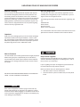
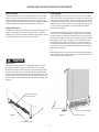
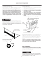
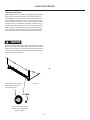
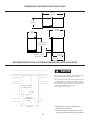
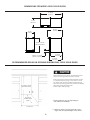
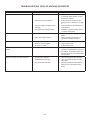
Installation
Operation
and
Maintenance
Instructions
Ice Machines
15CM
25CM
Freezer
15CAF
CONTENTS
Unpacking your ice machine or freezer ................................
Removing the packaging.....................................................
Warranty Registration..........................................................
Installing your ice machine or freezer ..................................
Selecting the location.........................................................
Cabinet Clearances..............................................................
Leveling legs........................................................................
Grounding method..............................................................
Electrical Requirements......................................................
Handle Installation ...............................................................
Door Alignment .....................................................................
Installing the ice machine water supply.................................
Using your ice machine.........................................................
Turning on your ice machine................................................
Ice machine operation........................................................
Using your freezer .................................................................
Dimensions For 15CM Solid Door...........................................
Recommended Rough in Opening Dimensions
For 15CM Solid Door...........................................................
Dimensions For 25CM Solid Door........................................
Recommended Rough in Opening Dimensions
For 25CM Solid Door...........................................................
Dimensions For 15CAF Solid Door ........................................
Recommended Rough in Opening Dimensions
For 15CAF Solid Door ..........................................................
Energy Saving Tips .................................................................
Features ................................................................................
Care and Cleaning.................................................................
Condenser air flow..............................................................
Cabinet ................................................................................
Interior ................................................................................
Defrosting instructions.........................................................
Troubleshooting your ice machine ........................................
Troubleshooting your ice machine or freezer ........................
Obtaining Service..................................................................
Commercial Product Warranty...............................................
Important Safety Instructions
3
3
3
4
4
4
4
5
5
5
6
7
8
8
8
9
10
Warnings and safety instructions appearing in this guide are not
meant to cover all possible conditions and situations that may
occur. Common sense, caution, and care must be exercised when
installing, maintaining, or operating this appliance.
Recognize Safety Symbols,
Words, and Labels.
CAUTION-Hazards or unsafe practices which could result in
personal injury or property or product damage.
10
11
11
12
WARNING-Hazards or unsafe practices which could result in
personal injury.
12
13
13
14
14
14
14
14
15
16
17
18
NOTE
NOTE-Important information to make a problem free installation.
2
is committed to building a quality product
in an environmentally friendly manner. Our processes are tightly
controlled and closely monitored. We have achieved certifications
in ISO 9001 for quality assurance, ISO 14001 for environmental
management, and OHSAS 18001 for occupational health and safety from Lloyd’s Register Quality Assurance.
UNPACKING YOUR ICE MACHINE OR FREEZER
Warranty Registration
Remove Packaging
It is important you send in your warranty registration card immediately after taking delivery of your ice machine or you can
register online at www.agamarvel.com.
Your ice machine has been packed for shipment with all parts
that could be damaged by movement securely fastened. Cut
the banding material at the bottom of the carton, unfold the
carton at the bottom, and remove the carton from the appliance.
Remove the plastic bag, styrofoam corner posts, and any tape
holding the door closed and internal components in place. The
owners manual is shipped inside the unit in a plastic bag along
with the warranty registration card.
The following information will be required when registering your
unit.
Model Number
Serial Number
Date of Purchase
Dealer’s name and address
The model number and serial number can be found on the serial
plate which is located on the bottom face inside the cabinet.
Important
Keep your carton packaging until your unit has been thoroughly
inspected and found to be in good condition. If there is damage, the packaging will be needed as proof of damage in transit.
Afterwards please dispose of all items responsibly in particular
the plastic bags which can be a suffocation hazard.
Note to Customer
This merchandise was carefully packed and thoroughly inspected
before leaving our plant. Responsibility for its safe delivery
was assumed by the retailer upon acceptance of the shipment.
Claims for loss or damage sustained in transit must be made to
the retailer.
Help Prevent Tragedies
Child entrapment and suffocation are not problems of the past.
Junked or abandoned refrigerators are still dangerous - even if
they sit out for “just a few days”.
If you are getting rid of your old refrigerator, please follow the
instructions below to help prevent accidents.
Before you throw away your old refrigerator or freezer:
• Take off the doors or remove the drawers.
• Leave the shelves in place so children may not easily climb
inside.
DO NOT RETURN DAMAGED MERCHANDISE TO THE MANUFACTURER - FILE THE CLAIM WITH THE RETAILER.
NOTE
If the unit was shipped or has been laying on its back for any
period of time allow the ice machine to sit upright for a period
of at least 24 hours before plugging in. This will assure oil returns
to the compressor. Plugging the ice machine in immediately may
cause damage to internal parts.
3
INSTALLING YOUR ICE MACHINE OR FREEZER
Select Location
Leveling Legs
The proper location will ensure peak performance of your appliance. We recommend a location where the unit will be out
of direct sunlight and away from heat sources. To assure your
product performs to specifications the recommended installation
location temperature range is from 65 to 90°F (18 to 32°C).
Adjustable legs at the front and rear corners of the unit should
be set so the unit is firmly positioned on the floor and level from
side to side and front to back. The overall height of your Marvel
refrigerator, depending on the model, may be adjusted from 241/8” (61.3cm) or 33-3/4” (85.7cm) with the leveling legs turned
in, and up to 25-1/8” (63.8cm) or 34-3/4” (88.3cm) with the
leveling legs extended.
Cabinet Clearance
Ventilation is required from the bottom front section of the unit.
Keep this area open and clear of any obstructions. Adjacent
cabinets and counter top can be installed around the unit as long
as the grille and door access remain unobstructed.
To adjust the leveling legs, place the refrigerator on a solid surface and protect the floor beneath the legs to avoid scratching
the floor. With the assistance of another person, lean the refrigerator back enough to access the front leveling legs and remove
the weight. Raise or lower the legs to the required dimension
by turning the legs. Repeat this process for the rear by tilting
the refrigerator forward using caution to prevent the door from
opening. On a level surface check the refrigerator for levelness
and adjust accordingly.
The front grille (toe kick) screws may be loosened and adjusted
to the desired height. When adjustment is complete tighten the
two toe kick screws. (See Figure 2).
Front Grille
Do not obstruct the front grill. The openings within the front
grill allow air to flow through the condenser heat exchanger.
Restrictions to this air flow will result in increased energy usage
and loss of cooling capacity. For this reason it is important this
area to not be obstructed and the grill openings kept clean. AGA
MARVEL does not recommend the use of custom made grills as
air flow may be restricted because of inadequate openings. (See
Figure 1).
Front Grille, keep
this area open.
Toe kick (Front Grille)
Figure 1
Figure 2
Front leveling legs
4
Toe kick screw
HANDLE INSTALLATION
Handle Installation (Solid Door Models)
•
•
1. Remove the handle, (2) screws, and 5/32” allen wrench from
the bag shipped inside the cabinet.
2. Locate handle opposite the hinges and secure in place using
the (2) screws and the allen wrench. (See Figure 4).
Do not splash or spray water from a hose on the ice machine! Doing so may cause an electrical shock, which may
result in severe injury or death.
This unit should not, under any circumstances, be installed
to an un-grounded electrical supply.
Screws
Grounding Method
Handle
This product is factory equipped with a power supply cord that
has a three-pronged, grounded plug. It must be plugged into a
mating grounding type receptacle in accordance with the National Electrical Code and applicable local codes and ordinances
(see Figure 3). If the circuit does not have a grounding type receptacle, it is the responsibility and obligation of the customer to
provide the proper power supply. The third ground prong should
not, under any circumstances, be cut or removed.
Electrical Connection
A 115 volt, 15 amp dedicated circuit is required. A 3 prong
grounded receptacle is required.
Figure 4
The unit must be installed according to your local building codes
and ordinances.
Right hand hinged
door shown
Do not use an extension cord with
this appliance.
Door Reversal
It is possible to reverse the door (change from right hand swing
to left hand swing or vice versa) if you wish. To do so it will be
necessary to order one of the service kits below.
Figure 3
5
Hinge Color
Door Color
Right Hand
Left Hand
Chrome
Black
42247595
42247599
Chrome
White
42247639
42247640
Black
Black
42247596
42247600
White
White
42247597
42247601
Stainless
Steel
Stainless
Steel
42247598
42247602
DOOR ALIGNMENT
Door Alignment Procedure
The door should be parallel to the sides and top of the refrigerator. If alignment is necessary the door may be adjusted by
loosening the 2 screws which secure the hinge adapter brackets
on the top and bottom of the door and adjusting the door side
to side. Use a 5/32” allen wrench for this procedure. (See Figure
5 below). When finished aligning the door, tighten the screws
securely.
Remove top
Hinge adapter bracket lohinge pin to recated on the top and bottom
move the door.
of the door.
9/32”
(7.1mm)
NOTE
For the door to close properly, it is necessary to maintain a
minimum space of 9/32” (7mm) between the door and cabinet
flange (See Figure 5). This space can be adjusted by adjusting the
top and bottom hinge adapter brackets.
Figure 5
Door must be
parallel to top
and sides of
refrigerator.
6
INSTALLING THE ICE MACHINE WATER SUPPLY
Water Supply
NOTE
Observe and follow all local building codes when installing this
appliance.
Attach the supplied water line adapter (Figure 7) to the water
valve inlet on the back of the ice machine (See Figure 6). Be sure
the rubber washer is in place in the inlet valve nut. Bend the
1/4” copper tubing to suit your installation being sure not to kink
the tubing. Use 1/4” copper tubing for your water supply which
is available at any local hardware or plumbing supply store.
When installing a water line for this unit a shutoff valve is recommended. NOTE: DO NOT USE A SELF-PIERCING TYPE VALVE.
The water line fitting supplied with your ice maker is to be used
on a 1/4 inch copper water supply line only. Do not attach a plastic supply line to your unit with this fitting.
Water pressure must be at a minimum of 20 psi for proper operation and a maximum of 120 psi.
Water supply
inlet
Make certain all water connections are watertight after installation. Form the tubing so that it will not vibrate against the
cabinet body or kink when your ice machine is set in position.
Figure 6
Back view of
ice machine
Rubber Washer
Adapter
Valve Fitting
Compression Fitting
Compression Nut
1/4 Diameter Copper water supply
line (supplied by customer)
From water supply
to ice maker
Figure 7
7
USING YOUR ICE MACHINE
Turning on the ice machine
Ice maker operation
After connecting the water supply, and setting your ice machine
in place plug the power cord into the wall receptacle. Then
place the switch located in the grille (see Figure 8) to the “ON”
position. The temperature control is factory preset, allow the ice
maker to run for 24 hours so the interior temperature will stabilize. If you wish to adjust the interior temperature use a small
bladed screwdriver pushed through the right hand side of the
grille to turn the temperature control shaft. Turning it clockwise
will make the unit colder. Turning it counterclockwise will make
it warmer. Turning it counterclockwise until it stops will shut off
the compressor and fan motor.
•
•
•
•
•
•
Make certain water pressure is at least 20 psi and no more
than 120 psi and the water is turned on.
The unit must be installed level for proper ice maker operation.
The shutoff arm wire must be down in its lowest position for
the ice maker to operate.
When the freezer section and ice maker unit has sufficiently
cooled, the ice maker will harvest ice cubes automatically.
When the ice bucket is full, the ice maker will automatically
shut off.
You may manually stop the ice maker by raising the shut off
arm to the locking position at the up most position.
Water adjustment screw behind cover
on side of housing
Should you turn off your control, allow at least five (5) minutes
before restarting in order to give the motor control time to automatically reset so that it can restart the motor. Electrical power
to your unit is controlled by the “ON/OFF” rocker switch located
in the front grille. (See Figure 8).
Cover
pulls off
Figure 9
“ON/OFF” Rocker
Switch in front grille
Arm down, ice maker
will operate
Arm up, stops operation
When operation of the appliance is to be discontinued for any
length of time, the ice cube cavity in the ice maker should be
emptied and dried. The water supply and power supply should
also be shut off and the ice bucket should be emptied and
cleaned.
Figure 8
Temperature control located
behind right side of air intake -exhaust grille.
If the ice is not used regularly, it will clump together with time.
For best ice results, discard ice in the bin as required and allow
the ice maker to make a new fresh batch of ice.
Water Fill Adjustment
If the water fill needs to be adjusted, turning the “water adjustment screw” (see Figure 9) clockwise increases the fill amount,
turning it counterclockwise decreases the fill amount. One complete revolution will affect fill by 40cc.
NOTE
Do not turn the “water adjustment screw” more than (1) 360°
revolution in either direction. Further adjustment than (1) revolution could damage the ice maker module.
8
USING YOUR FREEZER
Turning on the freezer
After setting the freezer in place, leveling (see page 4), plug the
power cord into the wall receptacle. The freezer should start
after plugging in. The temperature control is factory preset to a
mid range setting. Allow the freezer to run for 24 hours so the
interior temperature stabilizes. If you wish to adjust the interior
temperature use a small bladed screwdriver pushed through
the right hand side of the grille to turn the temperature control
shaft. Turning it clockwise will make the unit colder. Turning it
counterclockwise will make it warmer. Turning it counterclockwise until it stops will shut off the compressor and fan motor.
Should you turn off your control, allow at least five (5) minutes
before restarting in order to give the motor control time to automatically reset so that it can restart the motor. Electrical power
to your unit is controlled by the temperature control located in
the front grille. (See Figure 10).
Temperature control located
behind right side of air intake -exhaust grille.
Figure 10
Turn counterclockwise until
it stops to shut off the compressor and fan.
9
DIMENSIONS FOR MODEL 15CM SOLID DOOR
35-11/16”
(90.65cm)
15-7/8”
(40.34cm)
23-1/32”
(58.5cm)
14-7/8”
(37.8cm)
24-1/8” to 25-18”
(61.26 to 63.82cm)
3-15/16” to 4-15/16”
(10.01 to 12.54cm)
19-11/16”
(50.01cm)
21-25/32”
(55.32cm)
RECOMMENDED ROUGH IN OPENING DIMENSIONS,15CM SOLID DOOR
Electrical Requirements: A 115 volt, 15 amp dedicated circuit is
required. A 3 prong grounded receptacle is required.
Power outlet can be located in the back wall behind unit. Add
1” to depth for thickness of plug, or recess outlet 1” into the
wall. Power outlet can also be installed in adjacent cabinetry
with a cutout for routing of power cord. Follow all local building codes when installing electrical and unit.
Product weight = 72 lbs. ( 32.7kg.)
** 24-3/8” to 25-3/8”
(61.93 to 64.47cm)
*24” (61 cm)
standard cabinet
depth
* Depth dimension may vary depending on
each individual installation.
15” (38.1cm)
** Minimum rough in opening required is to be
larger than the adjusted height of the cabinet.
10
DIMENSIONS FOR MODEL 25CM SOLID DOOR
35-9/16”
(90.32cm)
15-7/8”
(40.34cm)
23-1/32”
(58.5cm)
14-7/8”
(37.8cm)
21-25/32”
(55.32cm)
33-3/4” to 34-3/4”
(85.7 to 88.3cm)
3” to 4”
(7.62 to 10.2cm)
19-11/16”
(50.09cm)
RECOMMENDED ROUGH IN OPENING DIMENSIONS, 25CM SOLID DOOR
Electrical Requirements: A 115 volt, 15 amp dedicated circuit
is required. A 3 prong grounded receptacle is required.
Power outlet can be located in the back wall behind unit. Add
1” to depth for thickness of plug, or recess outlet 1” into the
wall. Power outlet can also be installed in adjacent cabinetry
with a cutout for routing of power cord. Follow all local building codes when installing electrical and unit.
Product weight = 86 lbs. (39.1 kg.)
** 34” to 35”
(86.36 to 88.9cm)
*24” (61 cm)
standard cabinet
depth
* Depth dimension may vary depending on
each individual installation.
15” (38.1cm)
11
** Minimum rough in opening required is to be
larger than the adjusted height of the cabinet.
DIMENSIONS FOR MODEL 15CAF SOLID DOOR
35-11/16”
(90.32cm)
15-7/8”
(40.34cm)
23-1/32”
(58.5cm)
14-7/8”
(37.8cm)
24-1/8” to 25-1/8”
(61.26 to 63.82cm)
19-11/16”
(50.01cm)
3-15/16” to 4-15/16”
(10.01 to 12.54cm)
21-25/32”
(55.32cm)
RECOMMENDED ROUGH IN OPENING DIMENSIONS, 15CAF SOLID DOOR
Electrical Requirements: A 115 volt, 15 amp dedicated circuit
isrequired. A 3 prong grounded receptacle is required.
Power outlet can be located in the back wall behind unit. Add
1” to depth for thickness of plug, or recess outlet 1” into the
wall. Power outlet can also be installed in adjacent cabinetry
with a cutout for routing of power cord. Follow all local building
codes when installing electrical and unit.
Product weight = 70 lbs. (31.8 kg.)
** 24-3/8” to 25-3/8”
(61.93 to 64.47cm)
*24” (61 cm)
standard cabinet
depth
* Depth dimension may vary depending on
each individual installation.
15” (38.1cm)
** Minimum rough in opening required is to be
larger than the adjusted height of the cabinet.
12
FEATURES AND ENERGY SAVING TIPS
15CAF Features
Can be installed on the counter top or built in.
Temperature range = -4°C to -20°C.
Flat door liner.
Manual defrost.
15CM Features
Can be installed on the counter top or built in.
Makes crescent shaped ice cubes.
Temperature range = -7° to -20°C.
Flat door liner.
Manual defrost
No drain required.
25CM Features
Makes crescent shaped ice cubes.
Temperature range = -7° to -20°C.
Flat door liner.
Manual defrost
No drain required.
Probe Port (optional) for 15CAF
The optional probe port is a hole from the inside to the outside of
the unit, which could be located on the top, side, or back of the
unit. After inserting your wires or probe, seal the hole tightly with
caulk, putty, foam, etc. for proper operation.
Product Temperature versus Air Temperature
Air temperature moves up and down with door openings and
compressor run and off cycles. Air has little thermal mass and
therefore changes temperature relatively quickly as the unit
cycles on and off. Stored products have thermal mass so their
temperatures change much more slowly. While air temperature
may change 5 to 10 degrees C between run and off cycles, stored
product temperature typically changes less than 2 degrees C due
to their thermal mass. Always measure product temperature, not
air temperature, to determine if the products being stored are at
the proper temperature.
Energy Saving Tips
The following suggestions will minimize the cost of operating
your refrigeration appliance.
1. Do not install your appliance next to a hot appliance, (ovens,
glassware washers, etc.). heating air duct, or other heat
sources.
2. Install product out of direct sunlight.
3. Assure the toe grille vents at front of unit beneath door is
not obstructed and kept clean to allow ventilation for the
refrigeration system to expel heat.
4. Plug your appliance into a dedicated power circuit. (Not
shared with other appliances).
5. When initially loading your new product, or whenever large
quantities of warm contents are placed within refrigerated
storage compartment, minimize door openings for the next
12 hours to allow contents to pull down to compartment
set-point temperature.
6. Maintaining a relatively full storage compartment will require less appliance run time than an empty compartment.
7. Assure door closing is not obstructed by contents stored in
your appliance.
8. Allow hot items to reach room temperature before placing
in product.
9. Minimize door openings and duration of door openings.
10. Use the warmest temperature control set-point that provides the proper storage for your stored contents.
11. Set the control to the “off” position if cleaning the unit
requires the door to be open for an extended period of
time.
12. Annually clean condenser heat exchange coil located
in machine compartment underneath unit, (see “Care
and Cleaning” page 14).
13
CARE AND CLEANING
Condenser Air Flow
The condenser underneath the cabinet does not require frequent cleaning; however, satisfactory cooling depends on adequate ventilation over this heat exchanger.
It is recommended to annually clean the condenser by
vacuuming and brushing. To access the condenser, the
unit must be pulled out from the installation, and the
lower machine compartment access cover removed.
Defrosting Instructions 15CM and 25CM
1. Push the rocker switch located in the front grille to the
“OFF” position.
2. Remove the ice bucket and place a towel in the lower front
area of the ice maker to absorb the defrost water.
3. After defrosting is completed replace the ice bucket and
press the rocker switch to the “ON” position.
Defrosting Instructions 15CAF
Disconnect the power cord before cleaning the condenser.
Be sure that nothing obstructs the required air flow openings
in front of the cabinet. At least once or twice a year, brush or
vacuum lint and dirt from the front grille area (see page 4).
Cabinet
The painted cabinet can be washed with either a mild soap and
water and thoroughly rinsed with clear water. NEVER use abrasive scouring cleaners.
1. Disconnect the power cord and set the temperature control
to the off position. (See page 8).
2. Remove the contents from the freezer.
3. Place pans of hot water in the freezer if you wish to speed
up defrosting.
4. When defrosting is complete wipe out the interior and
replace the contents.
5. Connect power cord to outlet.
6. Set the temperature control to the desired level.
Interior
Wash interior compartment with mild soap and water. Do NOT
use an abrasive cleaner, solvent, polish cleaner or undiluted
detergent.
Care of Unit
1. Avoid leaning on the door, you may bend the door hinges or
tip the unit.
2. Exercise caution when sweeping, vacuuming or mopping
near the front of the unit. Damage to the grille can occur.
3. Periodically clean the interior of the unit as needed.
4. Periodically check and/or clean the front grille as needed.
Do not use an ice pick, knife, or any type of sharp object to
remove the ice. Doing so may puncture the units refrigerant
system and damage it beyond repair. You may speed up defrosting by filling the ice bucket with hot water and placing it back
into position.
14
TROUBLESHOOTING YOUR ICE MACHINE
Before You Call for Service
If the unit appears to be malfunctioning, read through this
manual first. If the problem persists, check the troubleshooting
guide below. Locate the problem in the guide and refer to the
cause and its remedy before calling for service. The problem may
be something very simple that can be solved without a service
call. However, it may be required to contact your dealer or a
qualified service technician.
Problem
Electrocution Hazard - Never attempt to repair or perform maintenance on the unit until the main electrical power has been
disconnected. Turning the unit control “OFF” does not remove
electrical power from the units wiring.
Possible Cause
Unit operates but does not produce any •
ice.
Remedy
The unit has just been started and it
has been less than 24 hours.
•
•
•
Water supply is not turned on.
Inadequate water pressure to unit.
•
•
•
The ice maker shut off arm is in the
uppermost position.
•
•
•
•
Freezer section has not reached
temperature.
Thermostat control set too warm.
•
Condenser fan air flow is restricted.
•
Room and/or water temperature is
too warm.
•
Small ice cubes.
•
Water input may require adjustment.
•
Due to differing water pressures, the
ice maker water input may require
adjustment. See Figure 9 on page 8
for water adjustment screw location.
Ice cubes are sticking together.
•
Ice consumption is low.
•
•
Room temperature is too warm.
•
Use the ice in the bin frequently. Ice
will stick together if left in insulated
bin over long periods of time.
Move the unit to an area that is
below 90°F.
15
•
•
Typical ice production is 8 pounds per
day. Allow for the freezer section to
reach temperature and the ice maker
to cycle and accumulate ice.
Turn on water supply to the unit.
Water pressure to the unit must be at
a minimum of 20 psi.
When the ice maker shut off arm is
in the uppermost position, the ice
maker is off. Flip the shut off arm
down to turn on the ice maker.
Allow the freezer section to reach
temperature.
Turn the temperature control clockwise to allow the unit to run colder.
Allow 24 hours before readjusting the
temperature control.
Make certain the grille in front of the
unit is free and open for air circulation. Clean grille as required.
Move the unit to an area where
ambient temperature is below 90°F.
The unit should not be placed next to
a heat source such as an oven. Check
for cold water connection.
TROUBLESHOOTING YOUR ICE MACHINE OR FREEZER
Problem
Unit too warm or too cold inside.
Possible Cause
Remedy
•
Control set too warm or cold.
•
•
Airflow to front grille blocked.
•
•
•
•
Excessive usage or prolonged door
openings.
Door gasket not sealing properly.
•
Unit not level.
•
•
Water line tubing vibration.
•
Unit will not run.
•
•
•
Unit turned off.
Power cord not plugged in.
No power at outlet.
•
•
•
Turn unit on. See page 8 or 9.
Plug in power cord.
Check house circuit.
Moisture collects on outside surface of
cabinet.
•
Hot and humid conditions.
•
Extremely hot and humid conditions
can cause condensation on outside of
the cabinet. As humidity and/or temperature decreases, the condensation
will disappear.
Moisture collects on inside of the unit.
•
•
To many door openings.
Prolonged door openings.
•
•
•
Hot and humid conditions.
•
Limit the amount of door openings.
Limit the amount of time with the
door open.
Extreme hot and humid conditions.
Move unit to a controlled environment.
Noise or Vibration.
16
•
Adjust temperature colder or warmer
as required. Allow 24 hours for temperature to stabilize.
Airflow must not be obstructed to
front grille. See “clearances” on page
4.
Allow temperature to stabilize for at
least 24 hours.
Check door alignment and/or adjust
or replace door gasket.
Level unit, see “Leveling Legs” on
page 4.
Adjust the tubing as necessary to
eliminate unwanted vibrations.
OBTAINING SERVICE
If Service is Required:
•
•
•
•
•
If the product is within the first year warranty period please
contact your dealer or call AGA MARVEL Customer Service
at 800.223.3900 for directions on how to obtain warranty
coverage in your area.
If the product is outside the first year warranty period, AGA
MARVEL Customer Service can provide recommendations of
service centers in your area. A listing of authorized service
centers is also available at www.agamarvel.com under the
service and support section.
In all correspondence regarding service, be sure to give the
model number, serial number, and proof of purchase.
Try to have information or description of nature of the problem, how long the unit has been running, the room temperature, and any additional information that may be helpful in
quickly solving the problem.
Table A is provided for recording pertinent information
regarding your product for future reference.
For Your Records
Date of Purchase
Dealer’s name
Dealer’s Address
Dealer’s City
Dealer’s State
Dealer’s Zip Code
Appliance Serial Number
Appliance Model Number
Date Warranty Card Sent (Must be
within 10 days of purchase).
Table A
17
COMMERCIAL PRODUCT WARRANTY
Entire Product - One Year Parts and Labor Warranty
AGA MARVEL warrants to the original purchaser that it will supply all necessary parts and labor to repair or replace in the end
user’s establishment, any component which is found by an authorized representative of AGA MARVEL to be defective in materials
or workmanship, subject to the conditions and exclusions stated
below, for a period of one year from the date of purchase by the
end user.
Refrigeration System - Additional Second Through Fifth Year
Parts Only Warranty
During the four years following expiration of the one year limited
warranty, AGA MARVEL warrants to the original purchaser that
it will supply replacement parts for the hermetically sealed refrigeration system which consists of the compressor, evaporator,
condenser, drier, and connecting tubing that are found to be defective in workmanship or materials. Other parts, labor costs, and
freight charges are the responsibility of the end user.
If AGA MARVEL is unable to repair or replace the defective product or component, AGA MARVEL shall issue a credit to the buyer
for all or part of the purchase price, as AGA MARVEL shall determine. The repair, replacement or payment in the manner described above shall be the sole and exclusive remedy of buyer for
a breach of this warranty.
Buyer must give written notice of any alleged defect in the product to AGA MARVEL within 30 days after discovery of the defect
by buyer. If notice is not given within such period, any claim for
breach of warranty shall be conclusively deemed to have been
waived, and AGA MARVEL shall not be liable under these warranties. AGA MARVEL or its agents shall be entitled to examine
the product. AGA MARVEL shall have the option of requiring the
return of the defective component, transportation prepaid, to establish the claim. The acceptance by AGA MARVEL of any component returned shall not be deemed an admission that the product
is defective or in breach of any warranty and, if AGA MARVEL determines that the product is not defective, the component shall
be reshipped to the buyer at the buyer’s expense. No component
will be returned to AGA MARVEL without its prior consent.
Nor do the above warranties cover failure of this product or its
components due to:
•
•
•
•
Transportation, damage sustained in transit or subsequent
damages.
Use in hostile environments or use for storage of contents
hostile to the product.
Improper installation, misuse, abuse, accident or alteration,
use on wiring not conforming to electrical codes, low voltages, failure to provide necessary maintenance, or other unreasonable use.
Parts or service not supplied or designated by AGA MARVEL.
The above warranties also do not apply if:
•
•
The original bill of sale, deliver date, or serial number cannot
be verified.
The refrigeration equipment is not in the possession of the
original end use purchaser.
The warranties set forth herein are the only warranties extended by AGA MARVEL and are in lieu of all warranties, express,
implied, statutory or otherwise. In particular, AGA MARVEL
makes no warranty of merchantability or fitness for a particular
purpose.
AGA MARVEL’s liability for any defect in the product shall not exceed the purchase price of the product. AGA MARVEL shall have
no liability for consequential damages of any kind whatsoever,
including, but not limited to, personal injury, property damage,
lost profits or other economic injury due to any defect in the
product.
No person, firm, or corporation is authorized to modify, expand or
extend these warranties, to waive any of the limitations or exclusions, or to make any other warranty or assume any other obligation for AGA MARVEL These warranties apply only to products
used in any of the fifty states of the United States and the District
of Columbia.
To obtain performance of this warranty, report any defects to:
The above warranties do not cover:
•
•
•
•
Shipping costs of replacement parts or returned defective
parts.
Customer education or instructions on how to use the refrigerator/freezer.
Any content loss, or incidental or consequential damage or
loss due to product failure.
Removal or installation.
1260 E. VanDeinse St.
Greenville MI 48838
Toll-Free: 800.223.3900
18
NOTES
19
www.agamarvel.com
1260 E. VanDeinse St.
Greenville MI 48838
800.223.3900
41011870-EN Rev J
4/23/12
All specifications and product designs subject to change without notice. Such revisions do not entitle the
buyer to corresponding changes, improvements, additions, replacements or compensation for previously
purchased products.