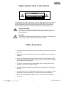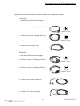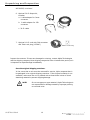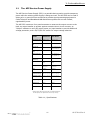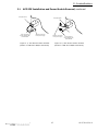
1
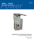
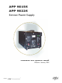
APP 9015S APP 9022S Service Power Supply Installation and Operation Manual Effective: January 2002 ® © 2002 TM This page intentionally blank ® APP 9015S APP 9022S Service Power Supply Installation and Operation Manual 016-537-B0-001, Re v. A January, 2002 © 2002 Alpha Technologies Purpose of this Manual: The purpose of the APP Service Power Supply Manual is to detail system features, system operation, options installation and maintenance procedures. It is written primarily for the system operator. NOTE: © 2002 Alpha Technologies products are subject to change through continual improvement processes. Therefore, specifications and/or design layouts may vary slightly from descriptions included in this manual. Updates to the manual will be issued when changes affect form, fit or function. TM 3 016-537-B0-001 Rev. A Table of Contents Contact Alpha ........................................................................... 6 Safety ...................................................................................... 7 Safety Symbols Used in this Manual ................................................................... 7 Safety Precautions ......................................................................................... 7 Utility Power Connection Notes ......................................................................... 8 Unpacking and Inspection ......................................................... 9 1. Introduction 1.1 The APP Service Power Supply ..................................................... 11 1.2 Theory of Operation ..................................................................... 12 1.3 APP Service Power Supply Features ............................................... 12 2. Installation 2.1 APP SPS Installation and Power Module Removal ............................... 16 3. Trouble-Shooting 3.1 Trouble-Shooting Guide ................................................................ 18 3.2 APP 9022S Schematic .................................................................. 20 3.3 Returns, Repair, and Parts Ordering ............................................... 21 Table of Figures Figure 1-1; Figure 1-2; Figure 2-1; Figure 2-2; Figure 3-1; APP 9015S Service Power Supply, Front Panel ........... APP 9022S Service Power Supply, Front Panel ........... 20A Service Power Inserter .................................... 25A Service Power Inserter .................................... APP 9022S Service Power Supply Schematic ............. 14 15 17 17 20 List of Tables Table 1-1; © 2002 TM Specifications ....................................................... 11 5 016-537-B0-001 Rev. A Contact Alpha General product information and customer service 7:00 AM to 5:00 PM Pacific Time 1-800-863-3930 To obtain complete technical support 7:00 AM to 5:00 PM Pacific Time or For after-hours emergency support 7 days per week, 24 hours a day 1-800-863-3364 016-537-B0-001 Rev. A 6 © 2002 TM Safety Safety Symbols Used in this Manual CAUTION HAZARDOUS CONDITION To reduce the risk of electrical shock, injury or death caused by moving parts or the explosion of fuel, and to ensure the safe operation of this unit, the following symbols have been placed throughout this manual. Where these symbols appear, servicing must only be performed by qualified personnel. Dangerous Voltage This symbol indicates that a dangerous voltage exists in this area of the product. Use caution whenever working in the area to prevent electrical shock. Attention This symbol indicates important installation, operation or maintenance instructions. Always follow these instructions closely. Safety Precautions © 2002 The APP Service Power Supply must be installed and serviced by qualified personnel. Always use proper lifting techniques whenever handling units, modules or batteries. Verify the voltage requirements of the equipment to be protected (load), the AC input voltage to the power supply (line), and the output voltage of the system prior to installation. The utility service panel must be equipped with a properly rated circuit breaker for use with this power supply. Do NOT exceed the output rating of the power supply, when connecting the load. Use a bucket truck or suitable climbing equipment, such as safety harness and spikes, whenever installing or servicing pole-mount installations. Do not let exposed battery cables come in contact with the chassis or enclosure. TM 7 016-537-B0-001 Rev. A Safety Utility Power Connection Notes CAUTION: Installation must be performed by qualified service personnel only, and in compliance with local electrical codes. Connection to utility power must be approved by the local utility before installing the power supply. CAUTION: A high magnetic trip breaker must be used in order to accommodate the high-inrush currents normally associated with the start-up of ferroresonant transformers (400 Amp, no-trip, first-half cycle). Do not replace this breaker with a conventional service entrance breaker. Alpha recommends only Airpax breakers because of increased reliability in this powering application. NOTE: 016-537-B0-001 Rev. A UL and NEC require that a service disconnect switch (UL listed) be provided by the installer and be connected between the power source and the Alpha power supply. Connection to the power supply must include an appropriate service entrance weather head. 8 © 2002 TM Unpacking and Inspection Verify that the following items have been included in the shipping container: APP 9015S: 1. APP 9015S Service Power Supply 2. Power cord with 5-20P plug (120VAC) NEMA 5-20 Plug 3. Power cord with 6-15P plug (240VAC) NEMA 6-15 Plug 4. Output cable, single Jones APP 9022S: 1. APP 9022S Service Power Supply 2. Power cord with 5-20P plug (120VAC) NEMA 5-20 Plug 3. Power cord with 6-15P plug (240VAC) NEMA 6-15 Plug 4. Y-cable with Jones connectors 5. Y-cable with 25A connectors © 2002 TM 9 016-537-B0-001 Rev. A Unpacking and Inspection APP 9022S, continued 6. Optional 30-Ft Output kit, includes: a. Y cable adapter for Jones connector a c b. Y cable adapter for 25A connector b c. 30-Ft cable 7. Optional 10-Ft cord with 30A connector and Twist Lock plug (125VAC) NEMA L5-30R Plug Inspect the contents. If items are damaged or missing, contact Alpha Technologies and the shipping company. Most shipping companies have a limited claim period, so it is important to report damage immediately. Save the original shipping container. In the event that a unit must be returned for service, Alpha requests that it be packaged in its original shipping container. If the original container is not available, make sure the unit is packed with at least three inches of shock absorbing material to prevent shipping damage. NOTE: 016-537-B0-001 Rev. A Do not use popcorn-type material. Alpha Technologies is not responsible for damage caused by improper packing on returned units. 10 © 2002 TM 1. Introduction 1.1 The APP Service Power Supply The APP Service Power Supply (SPS) is a portable device used to provide temporary power while the existing power supply is being serviced. The APP SPS can be used in either pole- or ground-mount enclosures to provide signal processing equipment in Cable Television and Broadband LAN distribution systems with current-limited, regulated AC power. The APP SPS contains a front panel ammeter to measure the output current to the load; an output breaker to protect against excessive short circuit currents; an "Output" indicator to verify AC output power; an input breaker to provide additional voltage protection; and a 60/75/90 VAC switch for output voltage selection. MODEL APP 9015S APP 9022S Input Volta ge (VAC ) 120/240 ± 15% 120/240 ± 15% Input Fre que ncy (Hz) 60 ± 3% 60 ± 3% Input C urre nt (A) 12 Output Volta ge (VAC ) 60/75/90 ± 5% Output C urre nt (A) 15 12.5 @ 240 VAC max* 18 @ 120 VAC max* 60/75/90 ± 5% 22A (240 VAC i n*) 17A (120 VAC i n*) Output Powe r (VA) (C ontinuous) 1350 1350/1650/1700 Output C urre nt Limit 150% of Out put Rat i ng 150% of Out put Rat i ng Efficie ncy 90% t ypi cal @rat ed l oad 90% t ypi cal @rat ed l oad Finish Fl at Bl ack Fl at Bl ack Ope ra ting T e mpe ra ture R a nge -40° F t o +122° F (-40° C t o +50° C) -40° F t o +122° F (-40° C t o +50° C) Dime nsions (in/mm) (H x W x D) 9" x 9.5" x 13.75"/ 241 x 229 x 349 9" x 9.5" x 13.75"/ 241 x 229 x 349 We ight (lbs/kg) 47/21 60/27 Enclosure T ype NEMA 1 NEMA 1 C e rtifica tions CSA Approved * Figures shown reflect use with power cord supplied with unit. For 22A @120V, use optional 30A 125V cord (27 A max). Table 1-1; Specifications © 2002 TM 11 016-537-B0-001 Rev. A 1. Introduction 1.2 Theory of Operation The APP SPS contains a ferroresonant transformer and a resonant capacitor. During AC LINE operation, utility power is fed into the primary winding of the ferroresonant transformer, T1. An AC capacitor, C1, forms the resonant circuit of the ferroresonant transformer which provides excellent noise and spike attenuation, short circuit current limiting, and output voltage regulation. Note: The ferroresonant transformer produces a "quasi" square wave output which resembles a rounded square wave. AC power enters the Service Power Supply where it is regulated (at the required output voltage) and passed onto the load via the Service Power Inserter (SPI) located inside the power supply enclosure. A switch, located on the SPI, toggles output power from the power supply requiring service to the APP SPS. NOTE: 1.3 When measuring the output voltage of ferroresonant transformers, use only a true RMS AC voltmeter. Non-RMS reading meters are calibrated to respond to pure sine waves and will not provide an accurate reading when measuring a "quasi" square wave output. APP Service Power Supply Features Output Current (Ammeter) The Ammeter displays output current flowing from the power module to the load. When there is no load at the output, the Ammeter reads zero. Output Breaker The AC output breaker protects the load from excessive durations of short circuit current, or an out-of-phase (or buck) condition. If the front panel ammeter reads zero, indicating no output to the load, this breaker must be checked, and reset if necessary. Input Breaker / Power Switch The AC input breaker protects the Service Power Supply from short circuit conditions, especially when it is used in conjunction with a generator during outage conditions. If the unit does not turn ON when power is applied, first verify that the unit is plugged into the convenience outlet and that the main AC circuit breaker is in the ON position. Output Power Indicator (9022) / Pilot Light (9015) The Output Power Lamp displays the presence of output AC voltage. 016-537-B0-001 Rev. A 12 © 2002 TM 1. Introduction 1.3 APP Service Power Supply Features, continued Output Voltage Selector The VAC switch is used to select the desired output voltage. Output options are 60, 75 and 90 Volts. NOTE: Verify that output voltage settings are correct before operating power supply. Do not rotate switch when unit is in operation. Always remove power from unit when selecting output settings. 60/ 75/ 90 VAC Output Connector The 60/ 75/ 90 VAC output connector supplies up to 22 Amps of power to a Service Power Inserter (SPI) through an output cable. Output Cables 9015S: Included with the APP 9015S is an output cable used to connect the Service Power Supply to the SPI, via a four-pin Jones connector. 9022S: Included with the APP 9022S are two 6-ft output "Y" cables. One cable terminates with two Jones connectors, and provides service power to one or two separate 20A SPIs. The other cable terminates with two 25A connectors, for 25A SPIs. Input Connector Input Connector is used to connect the APP SPS to line power through an AC line cord. The cord plugs directly into enclosure convenience outlet. The APP 9022S includes two power cords: One with a 5-20P plug to set voltage to 120 VAC; and one with a 6-15P plug to set voltage to 240 VAC. 9022s Option: 30-Ft Output Cables A 30-foot output kit is available. This kit provides "Y" cables for both 25A and Jones connectors. Alpha part number: 745-094-20. 9022S Option: 10-Ft Cord w/30A Connector and Twist Lock Plug (125VAC) For use with a twist lock receptacle, this line cord is equipped with a NEMA L5-30P plug. Alpha part number: 874-935-22. © 2002 TM 13 016-537-B0-001 Rev. A 1. Introduction 1.3 APP Service Power Supply Features, continued 8 2 1 3 7 5 4 6 Figure 1-1; APP 9015S Service Power Supply, Front Panel 1. 2. 3. 4. 5. 6. 7. 8. 016-537-B0-001 Rev. A Output Current 120/240V Input Voltage Selector 20 AMP AC Input Breaker/Power Switch 120/240V Input Connector Output Voltage Selector 60/75/90V Output Connector 20 AMP Output Breaker Pilot Light 14 © 2002 TM 1. Introduction 1.3 APP Service Power Supply Features, continued 2 1 7 3 5 6 4 Figure 1-2; APP 9022S Service Power Supply, Front Panel 1. 2. 3. 4. 5. 6. 7. © 2002 TM Output Current Output Power Indicator 30 AMP Output Breaker 60/75/90V Output Connector Output Voltage Selector 120/240V Input Connector 25 AMP AC Input Breaker/ Power Switch 15 016-537-B0-001 Rev. A 2. Installation 2.1 APP SPS Installation and Power Module Removal Procedure 1. Locate Service Power Inserter (SPI) in enclosure. (Refer to Figures 2-1 and 2-2.) For 20A SPI, plug APP SPS "Jones" connector into SPI. (Figure 2-1.) For 25A SPI (9022S model only), plug APP SPS into red and white 25A connectors. (Figure 2-2.) 2 Determine the line voltage of the UPS. 3. For APP 9015S model only: Select appropriate line voltage (120/240 VAC) by using the Input Voltage Selector switch. 4. Select and connect appropriate line cord to Input Connector and plug into outlet. CAUTION: Do not use the 120 VAC cord to plug into GFCI outlet! The GFCI outlet is intended for lights and tools only. If necessary, remove the LAP and use that outlet. 5. Set the 60/75/90 VAC selector switch to the desired voltage. Plug the APP SPS power cord into the enclosure's convenience outlet. (See Figures 2-3 and 2-4.) Switch the APP SPS ON, and verify that the output power indicator is lit. 6. Toggle the SPI's ALT/ON switch to ALT. This transfers output power from the module to the APP SPS which can now be used to maintain regulated, non-standby power to the cable plant until a replacement power module has been installed. 7. Switch the battery breaker on the power module OFF. 8. Unplug the power module LINE cord from the enclosure convenience outlet. 9. Wait approximately 1 minute for the power module capacitors to fully discharge. 10. Disconnect the wires from the power module. CAUTION: Do not let exposed battery cables come in contact with the chassis or enclosure. 11. Reverse this procedure when reinstalling a module. CAUTION: NOTE: 016-537-B0-001 Rev. A The ferroresonant transformer generates heat and may cause burns if handled with bare hands. Always test the power module for proper operation before toggling the SPI's "ALT/ON" switch back to the ON position. 16 © 2002 TM 2. Installation 2.1 APP SPS Installation and Power Module Removal, continued "ALT/ON" Switch "ALT/ON" Switch Jones Connector accepts mating plug from APP SPS Anderson connector from power supply Anderson Connector from power supply Figure 2-1; 20A Service Power Inserter (shown in PWE and UPE/M enclosures) © 2002 TM 25A Connectors accept mating plug from APP SPS Figure 2-2; 25A Service Power Inserter (shown in PWE and UPE/M enclosures) 17 016-537-B0-001 Rev. A 3. Trouble-Shooting 3.1 Trouble-Shooting Guide The trouble-shooting guide is designed to display typical symptoms, causes and solutions, starting with the most obvious and working systematically through the unit. Alpha Technologies recommends that the power supply maintenance log accompany units brought in for bench service to aid the technician in trouble-shooting the problem. Symptom #1: No output to cable; No AC line power; Green Output Power indicator OFF: Probable Cause: Solution: AC line cord unplugged Plug in AC line cord AC input circuit breaker tripped (or input fuse open) Reset AC circuit breaker Utility power outage Use voltmeter to verify correct voltage (120/240 VAC) at receptacle. Connect generator in the event of an extended power outage. Symptom #2: No output to cable; AC line power available; Green Output Power indicator ON; And Ammeter reads "0": Probable Cause: Solution: AC output breaker has tripped Reset output breaker SPI "ALT/ON" switch in wrong position Move switch to "ALT" position "Jones" connector loose or not connected to SPI Check connection Loose seizure screw inside SPI Tighten screw 016-537-B0-001 Rev. A 18 © 2002 TM 3. Trouble-Shooting 3.1 Trouble-Shooting Guide, Continued Symptom #3: Incorrect output voltage; And/or Ammeter reads excessive current (above rated output of APP SPS): © 2002 Probable Cause: Solution: 60/75/90 VAC switch in wrong position Move switch to required position Wrong type of voltmeter used Use true RMS voltmeter Under-loaded output (less than 1 Amp) Connect load Overloaded output Reduce load Short exists in load Locate and remove short MOV shorted in SPI Replace SPI APP 9015S only: 120/240 V switch in wrong position Set switch to correct line voltage TM 19 016-537-B0-001 Rev. A 3. Trouble-Shooting APP 9022S Schematic Figure 3-1; APP 9022S Service Power Supply Schematic 3.2 '$ /2 1(, / Preliminary 016-537-B0-001 Rev. A 20 © 2002 TM 3. Trouble-Shooting 3.3 Returns, Repair, and Parts Ordering Returns for Repair For units that must be returned for repair, Alpha requires a Return Material Authorization (RMA). An RMA can be obtained from Alpha Customer Service, using either method listed below: Download the necessary forms directly from Alpha's Web site, under "Customer Service": www.alpha.com Or call (800) 322-5742 for assistance. Clearly mark the RMA on the units original shipping container. If the original container is not available, make sure the unit is packed with at least three inches of shock absorbing material to prevent shipping damage. NOTE: Do not use popcorn-type material. Alpha Technologies is not responsible for damage caused by improper packing on returned units. In addition to the returned unit, please include a copy of the power supply maintenance log and any information relevant to the power supply failure. Returns for Credit For returns for credit, call (800) 322-5742. Parts and Ordering Information To order parts, contact the Alpha Technologies Customer Service Department directly at: United States and Latin America: Canada: United Kingdom: Germany: Middle East: (360) 647-2360 (604) 430-1476 44-279-422110 49-9122-997303 357-5-375675 To obtain emergency technical support (7 days/week, 24 hours/day) call: 1-800-322-5742 (USA) 1-800-667-8743 (CANADA) © 2002 TM 21 016-537-B0-001 Rev. A UNITED STATES ASIA PACIFIC LATIN AMERICA Alpha Technologies 3767 Alpha Way Bellingham, WA 98226 Tel: (360) 647-2360 Fax: (360) 671-4936 www.alpha.com CANADA Alpha Technologies 4084 McConnell Court Burnaby, B.C. V5A 3N7 Tel: (604) 430-1476 Fax: (604) 430-8908 UNITED KINGDOM Alpha Technologies Cartel Business Estate Edinburgh Way Harlow, Essex CM20 2DU Tel: +44-1279-422110 Fax: +44-1279-423355 www.alpha.com Protecting The Power in Communications. GERMANY Alpha Technologies Hansastrasse 8 D-91126 Schwabach Tel: +49-9122-79889-0 Fax: +49-9122-79889-21 MIDDLE EAST Alphatec P.O. Box 6468 3307 Limassol, Cyprus Tel: +357-5-375675 Fax: +357-5-359595 AUSTRALIA Alpha Technologies 8 Anella Ave., Unit 6 Castle Hill, NSW 2154 Tel: +61 (0)2 9894-7866 Fax: +61 (0)2 9894-0234 Due to continuing product development Alpha reserves the right to change specifications without notice. Copyright © 2002 Alpha Technologies, Inc. All rights reserved. Alpha is a registered trademark of Alpha Technologies. 016-537-B0-001 Rev. A