1
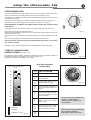
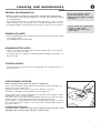
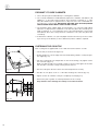
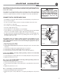
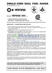
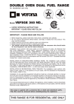
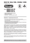
B U I LT- I N
CERAMIC
COOKTOP
Model
VEECT212F..
• USERS OPERATING INSTRUCTIONS
• INSTALLATION ADVICE
IMPORTANT - PLEASE READ AND FOLLOW
✓ Before beginning, please read these instructions completely and carefully.
✓ Do not remove permanently affixed labels, warnings, or plates from the product. This
may void the warranty.
✓ Please observe all local and national codes and ordinances.
✓ Please ensure that this product is properly grounded.
✓ The installer should leave these instructions with the consumer who should retain
for local inspector's use and for future reference.
✓ The electrical connection should always be accessible
Electrical installation must be in accordance with the National Electrical Code,
ANIS/NFPA70 - latest edition and/or local codes.
IN CANADA: Electrical installation must be in accordance with the current CSA C22.1
Canadian Electrical Codes Part 1 and/or local codes.
Dear Customer,
Thank you for having purchased and given your preference to our
product.
The safety precautions and recommendations reported below are for
your own safety and that of others. They will also provide a means by
which to make full use of the features offered by your appliance.
Please preserve this booklet carefully. It may be useful in future, either
to yourself or to others in the event that doubts should arise relating to
its operation.
This appliance must be used only for the task it has explicitly been
designed for, that is for cooking foodstuffs. Any other form of usage is
to be considered as inappropriate and therefore dangerous.
The manufacturer declines all responsibility in the event of damage
caused by improper, incorrect or illogical use of the appliance.
2
USER INSTRUCTIONS
IMPORTANT PRECAUTIONS AND RECOMMENDATIONS
✓ After having unpacked the appliance, check to ensure that it is not damaged.
If you have any doubts, do not use it and consult your supplier or a
professionally qualified technician.
✓ Packing elements (i.e. plastic bags, polystyrene foam, nails, packing straps,
etc.) should not be left around within easy reach of children, as these may
cause serious injuries.
✓ The packaging material is recyclable and is marked with the recycling symbol
.
✓ Do not attempt to modify the technical characteristics of the appliance as this
may become dangerous to use.
✓ The manufacturer cannot be considered responsible for damage caused by
unreasonable, incorrect or rash use of the appliance.
✓ If you should decide not to use this appliance any longer (or decide to
substitute an older model), before disposing of it, it is recommended that it be
made inoperative in an appropriate manner in accordance to health and
environmental protection regulations, ensuring in particular that all potentially
hazardous parts be made harmless, especially in relation to children who could
play with old appliances.
✓ The appliance should be installed and all the electrical connections made by a
qualified engineer in compliance with local regulations in force and following
the manufacturer's instructions
IMPORTANT PRECAUTIONS AND RECOMMENDATIONS
FOR USE OF ELECTRICAL APPLIANCES
Use of any electrical appliance implies the necessity to follow a series of
fundamental rules. In particular:
✓ Never touch the appliance with wet hands or feet;
✓ Do not operate the appliance barefooted;
✓ Do not allow children or disabled people to use the appliance without your
supervision.
The manufacturer cannot be held responsible for any damages caused by improper,
incorrect or unreasonable use of the appliance.
TIPS FOR THE USER
✓ During and after use of the cooktop, certain parts will become very hot. Do not
touch hot parts.
✓ Keep children away from the cooking hob when it is in use.
✓ Before any cleaning or maintenance, switch off the electricity to the cooktop.
Risk of fire!
✓ Do not leave inflammable material on the cooktop.
✓ Make sure that the electrical cables of other appliances installed nearby cannot
come into contact with the cooktop.
✓ Never cook the food directly on the vitroceramic surface, but in special pans or
containers.
3
features
SCHOTT
2
1
5
6
7
4
3
5
8
10
4
3
11
2
9
2
1
6
7
9
10
11
1
12
8
12
OFF
OFF
Fig. 1.1
3
5
7
6
4
VITROCERAMIC HOB (Fig. 1.1)
Electrical insulation Class I
COOKING POINTS
1. Zone Ø 145 - 1200 W
2. Zone Ø 180 - 1700 W
CONTROL PANEL DESCRIPTION
3. Rear zone control knob
4. Front zone control knob
5. Rear zone residual heat indicator
6. Front zone residual heat indicator
7. Power indicator light
4
using the vitroceramic hob
VITROCERAMIC HOB
The main characteristic of this pyroceram cooker top is that it permits rapid vertical transmission of the heat from the heating elements below to the saucepans on top.
The heat does not spread horizontally, however, and therefore the glass stays cold only a few
centimetres from the hob.
The hobs are controlled by the continuous energy regulation switch (0÷12) (fig. 2.1).
The heat intensity can be regulated continuously from “OFF” to “12” (max).
VERY IMPORTANT: TO SWITCH ON, ALWAYS LIGHTLY PRESS THE CONTROL KNOB
THEN TURN IT.
Check that the hob is clean and then switch on by press and turning the control knob.
When the top is working, the pilot light will be on.
When the hob temperature is above 60°C, the corresponding indicator light will come on to
indicate that the hob is hot.
This light will stay on even after the hob has been switched off to indicate that the hob is still
hot.
The residual heat persists for some time after the hob has been switched off.
5
6
7
8
4
3
9
10
2
11
1
12
OFF
Fig. 2.1
During this time avoid touching the hob and take particular care if there
are children nearby.
The light will go out automatically when the hob temperature drops below 60°C.
TYPES OF COOKING AREA
RADIANT ZONES
(Fig. 2.2a- 2.2b)
The heating element consists of electrical resistances which can operate together or
separately according to the setting of the energy regulator 0-12.
It reaches the required temperature very quickly.
Fig. 2.2a
ELECTRIC HOTPLATE
USAGE TABLE
Hob controlled by
continuous energy regulation switch
0 - 12
Position
of switch
1
Type of cooking
2
0
Switched OFF
3
1
2
For melting operations (of butter or chocolate)
2
3
4
To keep foods warm or heat
small quantities of water.
4
5
6
To heat greater quantities of
water and to whip creams and
sauces.
6
7
Slow boiling, e.g. spaghetti,
soups, boiled meats, to continue steam heating of roast
meats and stews.
7
8
For all kinds of fried foods,
steaks, cutlets and cooking
without a lid.
8
9
10
For browning of meat, cooked
potatoes, fried fish and for boiling large quantities of water.
11
12
Rapid frying, grilled steaks,
etc.
4
5
6
7
8
9
10
11
12
= Warming
= Cooking
= Roasting - Frying
Fig. 2.3
Fig. 2.2b
Do not scratch the cooktop with
cutting or sharp objects.
Do not use the cooktop as a
work surface.
Caution! the cooking hob becomes
very hot during operation.
Keep children well out of reach.
5
HINTS FOR SAFE USE OF THE HOBS
– Before switching on, check which knob controls the required hob. You are advised
to place the saucepan on the hob before switching on and to take it off after switching off.
– To switch on, always lightly press the control knob then turn it.
– Use saucepans with an even flat bottom (be careful of cast iron saucepans). Uneven
bottoms can scratch the pyroceram surface. Check that the bottom is clean and dry.
– Check that the saucepan handle does not protrude from the top to avoid knocking it
over. This precaution also makes it more difficult for children to reach the saucepan.
Fig. 2.4
– Do not use the top if the surface is broken or damaged.
– Do not bend over the hobs when they are on.
– Do not leave aluminium foil, greaseproof paper etc. or plastic on the hob when it is
hot.
– Remember that the hobs stay hot for quite a long time (approx. 30 min.) after they
have been switched off.
– Scrupulously follow the cleaning instructions.
– Do not drop heavy or sharp objects on the glass ceramic cooktop.
– If you note a crack in the cooktop, switch the appliance off immediately and call
the After-Sales Service.
– If the cooktop has halogen lamps, do not stare at them.
– Never cook the food directly on the glass ceramic cooktop, but in special pans or
containers.
6
cleaning and maintenance
GENERAL RECOMANDATION
✓ Before you begin cleaning you must ensure that the hob is switched off.
It is advisable to clean when the appliance is cold and especially when cleaning
the enamelled parts.
✓ All enamelled surfaces have to be washed with soapy water or some other nonabrasive product with a sponge and are to be dried preferably with a soft cloth.
✓ Avoid leaving alkaline or acid substances (lemon juice, vinegar etc.) on the surfaces.
Do not use steam jet cleaners
because the humidity could
infiltrate into the appliance making
it dangerous.
Do not scratch the cooktop with
cutting or sharp objects.
Do not use the cooktop as a
work surface.
ENAMELLED PARTS
✓ All the enamelled parts must be cleaned with a sponge and soapy water only or other
non-abrasive products.
Dry preferably with a chamois leather.
STAINLESS STEEL PARTS
✓ Stainless steel parts must be rinsed with water and dried with a soft and clean
cloth or with a chamois leather.
✓ For difficult dirt, use a specific non-abrasive product available commercially or a
little hot vinegar.
CONTROL KNOBS
✓ The control knobs may be removed for cleaning but care should be taken not to
damage the seal.
VITROCERAMIC SURFACE
Before cleaning the top, make sure that it is switched off.
Remove any encrustation using a special scraper which can be bought (fig. 3.1).
Remove dust using a damp cloth.
Detergents can be used as long as they are not abrasive or corrosive.
All residues of detergent must be eliminated with a damp cloth.
Keep all objects that could be melted by the heat away from the top: plastic objects,
aluminium foil, sugar or sugary products.
If an object melts on the top, remove immediately (while the top is still hot) using a
special scraper to avoid permanent damage to the pyroceram surface.
Avoid using knives and pointed objects as they could damage the surface of the top.
Also avoid using abrasive sponges or wire wool which can permanently scratch the
pyroceram surface.
Fig. 3.1
ATTENTION: MOST IMPORTANT!
If cleaning the glass ceramic hob using a special scraper tool take extra care to avoid
damaging to the seal at the edges of the glass ceramic surface.
7
INSTALLATION INSTRUCTIONS
WARNING!
THIS APPLIANCE HAS TO BE INSTALLED BY A QUALIFIED INSTALLER.
Improper installation, adjustment, alteration, services, or maintenance can cause injury or property damage. Consult a
qualified installer, service agent, or the gas supplier.
GENERAL INFORMATION
1. Installation must conform with local codes.
2. WARNING: This appliance shall not be used for space heating. This information is
based on safety considerations.
3. Keep appliance area clear and free from combustible materials, gasoline, and other
flammable vapors.
4. Disconnect the electrical supply to the appliance before servicing.
5. When removing appliance for cleaning and/or service;
A. Disconnect AC power supply.
B. Carefully lift appliance out of cabinet cutout.
CAUTION: Use care in handling.
6. Electrical Requirement
Electrical installation should comply with national and local codes.
WARNING!!
ELECTRICAL GROUNDING INSTRUCTIONS
The appliance must be electrically grounded in accordance with local codes or,
in the absence of local codes, with the National Electrical Code, ANSI/NFPA No.
70-latest edition. Installation should be made by a Iicensed electrician.
For personal safety, this appliance must be properly grounded.
REPLACEMENT PARTS
Only authorized replacement parts may be used in performing service on the cooktop.
Replacement parts are available from factory authorized parts distributors. Contact
the nearest parts distributor in your area.
8
COOKTOP DIMENSIONS
24”
(610 mm)
20” 1/16
(510 mm)
(CUT-OUT)
19” 9/32
(490 mm)
2” 23/64
(60 mm)
1” 31/32
(50 mm)
installation to the cabinet
11” 21/64
(288 mm)
7
5
8
9
11
1
12
OFF
6
7
4
3
8
9
2
11
1
2” 23/64
(60 mm)
BOX DIMENSIONS
1” 31/32
(50 mm)
6
2
min 3”
(76.2 mm)
form cut-out
2” 23/64
(60 mm)
5
4
3
(CUT-OUT)
10” 5/8
(270 mm)
1” 31/32
(50 mm)
20” 1/16
(510 mm)
SCHOTT
12
OFF
20” 1/16
(510 mm)
(CUT-OUT)
19” 9/32
(490 mm)
(CUT-OUT)
10” 5/8
(270 mm)
30”
(762 mm)
min
11” 13
(290 m/32
m)
min
3/32
11” 1 m)
(290 m
min
(76. 3”
2m
m)
from
cutout
3”
min 2 mm)
(76.
ut
cut-o
from
Fig. 4.2
18”
(457 mm)
max 13”
(330 mm)
max 13”
(330 mm)
18”
(457 mm)
1” 31/32
(50 mm)
min 3”
(76.2 mm)
form cut-out
30”
(762 mm)
2” 23/64
(60 mm)
24”
(610 mm)
Fig. 4.1
9
PROXIMITY TO SIDE CABINETS
1. The cooktop may be installed directly to existing base cabinets.
2. The cooktop CANNOT be installed directly adjacent to sidewalls, tall cabinets, tall
appliances, or other side vertical surfaces. There must be a minimum of 3” (76.2
mm) side clearance (left or right) from the cooktop cut-out to such combustible surface above the counter heigh. IMPORTANT: ONE SIDE (LEFT OR RIGHT) ABOVE
THE COUNTER HEIGHT MUST AWAYS BE KEPT CLEAR.
3. The maximum upper cabinet depth recommended is 13” (330 mm). Wall cabinet
above the cooktop must be a minimum of 30” (762 mm) above the countertop for a
width of minimum 11” 13/32 (290 mm): it has to be centred with the cooktop. Side
wall cabinets above the cooktop must be a minimum of 18” (457 mm) above the
countertop.
4. If cabinet has a drawer, a 4” (102 mm) depth clearance from the top of the countertop to the top of the drawer (or other obstruction) in base cabinet is required.
FASTENING THE COOKTOP
A
A
Each cooking hob is supplied with a set of tabs and screws fasten it on units.
✓ Cut the unit (as shown in the figure 4.1).
A
✓ Stretch gasket “D” over the edge of the hole made, being careful to overlay the junction edges (fig. 4.4).
A
✓ Turn the cooking hob over and put tabs “A” into the mountings, only tighten screws
“B” a few turns (fig. 4.3).
Make sure that the tabs are mounted correctly as shown in the figures at the side.
Turn the tabs so that the cooktop can be put into the hole.
✓ Put the cooktop into the hole cut into the unit and position it correctly.
Fig. 4.3
✓ Put tabs “A”; into place, tooth “C” of the tabs should go into the hole (fig. 4.4).
C
✓ Tighten screws “B” until the cooktop is completely secured (fig. 4.4).
D
B
Fig. 4.4
10
A
40 mm max.
30 mm min.
✓ Remove the part of gasket “D” which protrudes from the cooktop.
Keep attention not to damage the cooktop or the cabinet surface.
electrical connection
This appliance must be connected to a grounded, metallic permanent wiring system or a ground connector should be connected to the ground terminal or wire
lead on the cooktop.
This appliance is manufactured with a frame connected, green or bare ground wire.
Connect the cooktop cable to the junction box through the CSA or UL-listed conduit
connector. Complete electrical connection according to local codes and ordinances.
WARNING
TO AVOID ELECTRICAL SHOCK
HAZARD, BEFORE INSTALLING THE
APPLIANCE, SWITCH POWER OFF AT
THE SERVICE PANEL AND LOCK THE
PANEL TO PREVENT THE POWER
FROM BEING SWITCHED ON
ACCIDENTALLY.
CONNECT WITH COPPER WIRE ONLY
✓ The flexible (4’) armoured cable should be connected directly to the junction box.
✓ Do not cut the conduit.
✓ A CSA or UL-listed conduit connector must be provided at the junction box.
✓ Do not ground to a gas pipe.
✓ Do not have a fuse in the grounding or neutral circuit.
3-wire cable from
power supply
✓ Fuse both supply (phase) lines.
✓ A time delay fuse or circuit breaker is recommended.
Junction box
Black wires
✓ Connect directly to the fused disconnect (or circuit breaker box) through flexible,
armored or non-metallic shealted, copper cable (with grounding wire).
Red wires
✓ If codes permit and a separate grounding wire is used, it is recommended that a
qualified electrician determine that the grounding path and wire gauge is in
accordance with local codes.
White
wire
This appliance does not require a neutral connection. If the appliance is to be
completely enclosed in a cabinet, feed the appliance cable through the opening
in the cabinet. Make the electrical connection following the appropriate steps for
your installation.
1. Disconnect the power supply.
2. Remove the junction box cover.
3. Connect the cooktop cable to the junction box through the CSA or UL-listed conduit
connector.
4. Connect the two black wires together with twist-on connectors.
5. Connect the two red wires together with twist-on connectors.
6. Connect electrical connection according to local codes and ordinances.
Green & yellow
wire
CSA or UL-listed
conduit connector
to appliance
Fig. 5.1
4-wire cable from
power supply
If local codes PERMIT connecting cabinet-grounding conductor to neutral white
wire in the junction box:
Junction box
7. Connect the green cooktop cable wire to the neutral (white) wire in the junction box.
8. Replace the junction box cover.
Red wires
White wire
OR If local codes DO NOT PERMIT connecting cabinet-grounding conductor to
neutral white wire in junction box:
7. Terminate neutral (white) wire in junction box.
8. Connect the green grounding cooktop cable wire to a grounded wire in the junction
box.
9. Replace the junction box cover.
OR
If connecting to a four-wire electrical system:
Green & yellow
wires
Black wires
CSA or UL-listed
conduit connector
to appliance
Fig. 5.2
7. Terminate neutral (white) wire in junction box.
8. Connect the green cooktop cable wire to the green grounding wire in the junction
box.
11
The manufacturer cannot be held responsible for possible inaccuracies due to printing or transcription errors in
the present booklet.
The manufacturer reserves the right to make all modifications to its products deemed necessary for manufacture
or commercial reasons at any moment and without prior notice, without jeopardising the essential functional and
safety characteristics of the appliances.
code 1103612 ß1