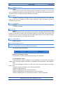
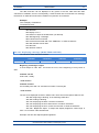
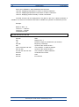
1
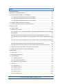
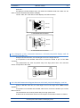
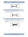
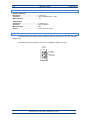
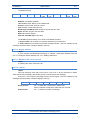
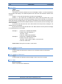
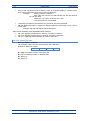
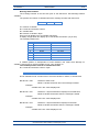
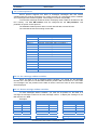
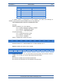
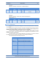
OPERATION MANUAL FOR DISPLAYS OF SERIES DT-203X, DT-105X AND DT-110X 0939K21I Index 1. INTRODUCTION .................................................................................................................... 1-1 2. GENERAL CHARACTERISTICS. .......................................................................................... 2-1 2.1. Electrical characteristics of the displays .......................................................................... 2-1 2.1.1. Electrical characteristics of the DT-203 displays. ..................................................... 2-1 2.1.2. Electrical characteristics of the DT-105 displays. ..................................................... 2-1 2.1.3. Electrical characteristics of the DT-110 displays. ..................................................... 2-1 2.2. Display weight and power consumption. ......................................................................... 2-2 2.3. Dimensions of the DT-203, DT-105 and DT-110. ............................................................ 2-3 3. INSTALLATION ...................................................................................................................... 3-1 3.1. Power supply. .................................................................................................................. 3-1 3.2. Serial line connection ....................................................................................................... 3-2 3.2.1. Diagram of the connection between a DT-105/110/203X display and PC computer using RS-232. ..................................................................................................................... 3-3 3.2.2. RS-485 Connection diagram between 3 DT-105/110/203X displays , and PC. ....... 3-3 3.2.3. RS-422 Connection between DT-105/110/203X, and a SCB41 OMRON connection kit. ........................................................................................................................................ 3-4 3.2.4. RS-422 connection between DT-105/110/203X, and a LK202 OMRON connection kit ............................................................................................................................................ 3-4 3.2.5. RS-232 Connection between DT-105/110/203X, and Omron PLC. ......................... 3-5 3.2.6. RS-485 Connection between DT-105/110/203X, and a Siemens PLC S7-200........ 3-5 3.3. Characteristics of temperature & humidity probe. (Option) ............................................. 3-6 3.4. Wiring of temperature & humidity probe (Option) ............................................................ 3-6 4. OPERATION .......................................................................................................................... 4-1 4.1. Initial reset........................................................................................................................ 4-1 4.2. Message programming .................................................................................................... 4-1 4.3. Set parameters. ............................................................................................................... 4-1 4.3.1. Modify parameters .................................................................................................... 4-2 4.3.2. Exit modify parameters ............................................................................................. 4-2 4.3.3. Meaning of each parameter. ..................................................................................... 4-2 4.4. Protocols. ......................................................................................................................... 4-4 4.4.1. TDL protocol. ............................................................................................................. 4-5 4.4.2. ModBus protocol. .................................................................................................... 4-10 4.4.3. Omron protocol. ...................................................................................................... 4-17 4.4.4. ASCII protocol. ........................................................................................................ 4-20 4.4.5. S7-200 protocol. ...................................................................................................... 4-21 DT-203X, DT-105X and DT-110X display series CHAPTER 1 INTRODUCTION 1-1 1. INTRODUCTION The alphanumerical displays for series DT-203X, DT-105X and DT-110X, are industrial displays for control by RS-232 and RS-485 serial interface, which can be configured to work with several protocols. The selection of the parameters and the communication protocol is done using two buttons with a system of easily programmable menu. One of its main characteristics is the height of the characters: DT-203X of 30mm, readable from up to 15m. DT-105X of 50 mm, readable from up to 25m. DT-110X of 100 mm, readable from up to 50m. As with other display series, the DT-203X, DT-105X and DT-110X series is also available in one or two-sided versions, which provides multiple solutions and installation possibilities. It is surface mounted, with fixtures to a wall or partition wall, or suspended by the side anchoring. The application field of these displays is very wide in all types of industrial applications. They can be used to display Scada program values, counter values from a PLC, warning messages, and advertisements. RS-232/485 DT-203X, DT-105X and DT-110X display series CHAPTER 2 GENERAL CHARACTERISTICS 2-1 2. GENERAL CHARACTERISTICS. 2.1. Electrical characteristics of the displays 2.1.1. Electrical characteristics of the DT-203 displays. Supply Voltage........................................... 88 to 264 VAC 47 to 63Hz. Consumption ............................................. See “Display weight and power consumption.” ..................................................................... High brightness displays multiply its ..................................................................... power consumption per 5 Display ....................................................... 7x5 Dot matrix of 30mm high. ..................................................................... Red Led colour. Visibility 15 meters. Parameter memory .................................... Eeprom. Watch calendar .......................................... Second / Minute / Hour / Day / Month / Year. Environmental Conditions ........................ Operating Temperature: 0 to 50ºC. ..................................................................... Storage temperature: -10ºC to 60ºC. ..................................................................... Humidity: 5-95% RH non condensing. ..................................................................... Maximum environmental illumination: 1000 lux. ..................................................................... Sealing: IP41. RS232/RS485 port series .......................... For recording the initial messages in EEPROM and ..................................................................... activate messages from the control series device. 2.1.2. Electrical characteristics of the DT-105 displays. Supply Voltage........................................... 88 to 264 VAC 47 to 63Hz. Consumption ............................................. See “Display weight and power consumption.” ..................................................................... High brightness displays multiply its ..................................................................... power consumption per 5 Display ....................................................... 7x5 Dot matrix of 50mm high. ..................................................................... Red Led colour. Visibility 25 meters. Parameter memory .................................... Eeprom. Watch calendar .......................................... Second / Minute / Hour / Day / Month / Year. Environmental Conditions ........................ Operating Temperature: 0 to 50ºC. ..................................................................... Storage temperature: -10ºC to 60ºC. ..................................................................... Humidity: 5-95% RH non condensing. ..................................................................... Maximum environmental illumination: 1000 lux. ..................................................................... Sealing: IP41. RS232/RS485 port series .......................... For recording the initial messages in EEPROM and ..................................................................... activate messages from the control series device. 2.1.3. Electrical characteristics of the DT-110 displays. Supply Voltage........................................... 88 to 264 VAC 47 to 63Hz. Consumption ............................................. See “Display weight and power consumption.” ..................................................................... High brightness displays multiply its ..................................................................... power consumption per 5 Display ....................................................... 7x5 Dot matrix of 100mm high. ..................................................................... Red Led colour. Visibility 50 meters. Parameter memory .................................... Eeprom. Watch calendar .......................................... Second / Minute / Hour / Day / Month / Year. Environmental Conditions ........................ Operating Temperature: 0 to 50ºC. ..................................................................... Storage temperature: -10ºC to 60ºC. ..................................................................... Humidity 5-95% RH non condensing. ..................................................................... Maximum environmental illumination: 1000 lux. ..................................................................... Sealing: IP41. RS232/RS485 port series .......................... For recording the initial messages in EEPROM and ..................................................................... activate messages from the control series device. DT-203X, DT-105X and DT-110X display series 2-2 GENERAL CHARACTERISTICS CHAPTER 2 2.2. Display weight and power consumption. Reference DT-105/1S-6 DT-105/1D-6 DT-105/1S-13 DT-105/1D-13 DT-105/1S-20 DT-105/1D-20 DT-105/1S-26 DT-105/1D-26 DT-105/1S-33 DT-105/1D-33 DT-105/1S-40 DT-105/1D-40 DT-105/2S-6 DT-105/2D-6 DT-105/2S-13 DT-105/2D-13 DT-105/2S-20 DT-105/2D-20 DT-105/2S-26 DT-105/2D-26 DT-105/2S-33 DT-105/2D-33 DT-105/2S-40 DT-105/2D-40 DT-105/3S-6 DT-105/3D-6 DT-105/3S-13 DT-105/3D-13 DT-105/3S-20 DT-105/3D-20 DT-105/3S-26 DT-105/3D-26 DT-105/3S-33 DT-105/3D-33 Display Weight (kg) 4 4 5,5 6 7 8 9 10 10,5 12 12 14 5 5,5 7 8 9 10,5 11 13,5 13,5 16 15,5 19 5,5 6,5 8,5 10 11 13,5 13,5 17 16 20,5 Power (W) 2 4 3,635 7,27 5,4 10,8 7,12 14,24 8,5 17 10,125 20,25 DT-105/3S-40 DT-105/3D-40 DT-105/4S-20 DT-105/4D-20 DT-105/5S-20 DT-105/5D-20 DT-105/6S-20 DT-105/6D-20 DT-105/7S-20 DT-105/7D-20 DT-105/8S-20 DT-105/8D-20 18,5 24 12,5 16 14,5 18,5 16,5 21,5 18 24 20 27 Reference 4 8 7,27 14,54 10,8 21,6 14,24 28,48 17 34 20,25 40,5 6 12 10,905 21,81 16,2 32,4 21,36 42,72 25,5 51 DT-110/1S-6 DT-110/1D-6 DT-110/1S-13 DT-110/1D-13 DT-110/1S-20 DT-110/1D-20 DT-110/1S-26 DT-110/1D-26 DT-110/2S-6 DT-110/2D-6 DT-110/2S-13 DT-110/2D-13 DT-110/2S-20 DT-110/2D-20 DT-110/2S-26 DT-110/2D-26 DT-110/3S-6 DT-110/3D-6 DT-110/3S-13 DT-110/3D-13 DT-110/3S-20 DT-110/3D-20 DT-110/3S-26 DT-110/3D-26 DT-110/4S-20 DT-110/4D-20 DT-110/5S-20 DT-110/5D-20 DT-110/6S-20 DT-110/6D-20 DT-110/7S-20 DT-110/7D-20 DT-110/8S-20 DT-110/8D-20 Display Weight (kg) 6,5 7,5 10,5 13 14,5 18 19 23,5 9 11,5 15 20 21 28 27 36,5 12 15,5 20 27 27,5 38,5 35,5 49,5 34 48,5 41 58 47,5 68,5 53,5 78,5 60 88,5 4 8 7,27 14,54 10,8 21,6 14,24 28,48 6 12 10,905 21,81 16,2 32,4 21,36 42,72 21,6 43,2 27 54 32,4 64,8 37,8 75,6 43,2 86,4 30,375 60,75 21,6 43,2 27 54 32,4 64,8 37,8 75,6 43,2 86,4 DT-203/2S-20 DT-203/2D-20 DT-203/2S-40 DT-203/2D-40 DT-203/4S-20 DT-203/4D-20 DT-203/4S-40 DT-203/4D-40 DT-203/6S-20 DT-203/6D-20 DT-203/8S-20 DT-203/8D-20 6 6,5 9 10,5 7,5 9 12 15 9 11,5 11 14 5 10 10 20 10 20 20 40 15 30 20 40 DT-203X, DT-105X and DT-110X display series Power (W) 2 4 3,635 7,27 5,4 10,8 7,12 14,24 CHAPTER 2 GENERAL CHARACTERISTICS 2-3 2.3. Dimensions of the DT-203, DT-105 and DT-110. DT-105/1S(D)-6 DT-105/1S(D)-13 DT-105/1S(D)-20 DT-105/1S(D)-26 DT-105/1S(D)-33 DT-105/1S(D)-40 DT-105/2S(D)-6 DT-105/2S(D)-13 DT-105/2S(D)-20 DT-105/2S(D)-26 DT-105/2S(D)-33 DT-105/2S(D)-40 DT-105/3S(D)-6 DT-105/3S(D)-13 DT-105/3S(D)-20 DT-105/3S(D)-26 DT-105/3S(D)-33 DT-105/3S(D)-40 DT-105/4S(D)-20 DT-105/5S(D)-20 DT-105/6S(D)-20 DT-105/7S(D)-20 DT-105/8S(D)-20 DT-110/1S(D)-6 DT-110/1S(D)-13 DT-110/1S(D)-20 DT-110/1S(D)-26 DT-110/2S(D)-6 DT-110/2S(D)-13 DT-110/2S(D)-20 DT-110/2S(D)-26 DT-110/3S(D)-6 DT-110/3S(D)-13 DT-110/3S(D)-20 DT-110/3S(D)-26 DT-110/4S(D)-20 DT-110/5S(D)-20 DT-110/6S(D)-20 DT-110/7S(D)-20 DT-110/8S(D)-20 DT-203/2S(D)-20 DT-203/2S(D)-40 DT-203/4S(D)-20 DT-203/4S(D)-40 DT-203/6S(D)-20 DT-203/8S(D)-20 A 375 680 985 1290 1595 1900 375 680 985 1290 1595 1900 375 680 985 1290 1595 1900 985 985 985 985 985 666 1276 1886 2496 666 1276 1886 2496 666 1276 1886 2496 1886 1886 1886 1886 1886 615 1170 615 1170 615 615 B C D E F 122 109 X X X 122 109 X X X 122 109 X X X 122 109 X X X 122 109 X X X 122 109 X X X 230 112 X X X 230 112 X X X 230 112 X X X 230 112 X X X 230 112 X X X 230 112 X X X 338 X 72 186 X 338 X 72 186 X 338 X 72 186 X 338 X 72 186 X 338 X 72 186 X 338 X 72 186 X 436 X 72 292 X 542 X 92 358 X 648 X 112 424 X 754 377 72 610 305 860 430 72 716 358 177 82,5 X X X 177 82,5 X X X 177 82,5 X X X 177 82,5 X X X 378 X 80 218 X 378 X 80 218 X 378 X 80 218 X 378 X 80 218 X 591 X 80 430 X 591 X 80 430 X 591 X 80 430 X 591 X 80 430 X 805 403 80 646 322,5 1018 509 80 858 429 1232 616 80 1072 536 1445 723 80 1286 643 1654 830 80 1500 750 177 85 X X X 177 85 X X X 317 X 72 173 X 317 X 72 173 X 464 X 91 282 X 611 X 112 387 X See the draw on the next page G 358 663 968 1273 1578 1883 358 663 968 1273 1578 1883 358 663 968 1273 1578 1883 968 968 968 968 968 649 1259 1869 2479 649 1259 1869 2479 649 1259 1869 2479 1869 1869 1869 1869 1869 598 1153 598 1153 598 598 DT-203X, DT-105X and DT-110X display series P1 O O O O O O O O O O O O X X X X X X X X X O O O O O O X X X X X X X X O O O O O O O X X X X P2 X X X X X X X X X X X X O O O O O O O O O O O X X X X O O O O O O O O O O O O O X X O O O O P3 X X X X X X X X X X X X O O O O O O O O O O O X X X X O O O O O O O O O O O O O X X O O O O 2-4 GENERAL CHARACTERISTICS CHAPTER 2 Measures in millimetres. X = Not valid for these model. P1, P2 and P3: Anchorage point. Used = O. Not used = X. Anchorage holes position on the wall. See valid point (P1, P2 o P3) on the table in the previous page. A D 120 E B F C P2 40 Ø5 F P2 F P1 P3 G DT-203X, DT-105X and DT-110X display series D P3 C F P1 CHAPTER 3 INSTALLATION 3-1 3. INSTALLATION The installation of the DT-203X, DT-105X and DT-110X, is not particularly delicate, but some important considerations must be taken into account. It must not be anchored to places subject to vibrations, nor should it be installed in places which generally surpass the limits specified in the display characteristics, both in terms of temperature and humidity. The degree of protection of displays DT-203X, DT-105X and DT-110X is IP41, meaning that they are protected against penetration by solid foreign objects of a diameter of about 1mm and against the vertical fall of water droplets. Displays DT-203X, DT-105X and DT-110X, should not be installed in places with illumination level higher than 1000 lux. Neither should the display be placed in direct sunlight as visibility would be lost. In the electrical installation, proximity to lines of high intensity circulation and high voltage lines must be avoided, as well as proximity to High Frequency generators and U/F converters for motors. 3.1. Power supply. The power supply must be 88 to 264 VAC 47 to 63Hz. The power supply conductor section will be in line with consumption and the ground conductor will be a minimum section of 1.5mm². Although the displays are specially prepared for environments with high levels of electrical noise, should you suspect that the power supply line is very noisy, we advise a separating transformer be connected between the supply line and the display and/or an exterior network filter be connected. The power supply connector has 3 contacts and is situated in the lower part of the unit. Connect the power wires following the schema below 3 2 1 1- 230V 2- 230V 3- GND DT-203X, DT-105X and DT-110X display series 3-2 INSTALLATION CHAPTER 3 3.2. Serial line connection In DT-105X, DT-110X and DT-203X displays, serial line has a double function. 1) To transfer texts into the display using a PC and TDLWin program. The TDLWin program is the tool you need to edit, save and transfer the messages. The TDLWin program sets the computer serial port with these parameters: Baud rate: 9600 Parity: Even Nº of bits: 8 Stop bits: 2 2) Communication with serial RS232/RS485 units using buit-in protocols. See 0 “ DT-203X, DT-105X and DT-110X display series CHAPTER 3 INSTALLATION 3-3 Protocols.” All displays DT105/110/203/X may use RS232 and RS485 serial lines. Both use the same connector located at the bottom of display. The DT-105X, DT-110X and DT-203X displays use DB9 connector. DB9 Plug 1 2 3 4 5 6 7 8 9 Rx Tx Dtr GND Dsr A B RS-232 RS-485 1. RS-232/RS-485 connector DB9 Plug 1 2 3 4 5 6 7 8 9 Rx Tx GND A RX+ B RXA TX+ B TX- RS-232 RS-422 2. RS-232/RS-422 connector 3.2.1. Diagram of the connection between a DT-105/110/203X display and PC computer using RS-232. Using an RS-232 serial line, the total length must not be longer than 5m. It is important to use shielded cable and to connect the shield to pin 9 of the DB9 connector. The transmission line must be placed away from high power lines. The connector shown corresponds to the cable. DB9 Socket 2 3 5 9 Display DB9 Socket 2 3 5 Computer 3.2.2. RS-485 Connection diagram between 3 DT-105/110/203X displays , and PC. Using an RS-485 serial line, the total length must not be longer than 1000m without amplifiers. Is important to use twisted and shielded cable and to connect the shield to pin 9 of the DB9 connector. The transmission line must be placed away from high power lines. At both ends of transmission line there must be place a termination resistor of 120ohm. DT-203X, DT-105X and DT-110X display series 3-4 INSTALLATION CHAPTER 3 DB9 Socket 120Ω 7 8 PC Display DB9 Socket 7 8 Display DB9 Socket 7 8 9 120Ω Display 3.2.3. RS-422 Connection between DT-105/110/203X, and a SCB41 OMRON connection kit. In a RS-422 connection the line length must not surpass 1000m, without amplifiers It is necessary to use shielded pair cable and to connect, between the display and the converter, the screen to pin 9 in the DB9 connector. The transmission line must be placed away from high power lines. Branches from the network to the displays must be as short as possible. Resistors of 120 Ohm must be set at the end of the line to ensure that the network is in good working order. In connector DB9 there is enough space to set the resistance together with the connection. DB9 Socket 6 4 8 7 9 Display DB9 Socket 1 2 6 8 PLC Omron SCB41 3.2.4. RS-422 connection between DT-105/110/203X, and a LK202 OMRON connection kit In a RS-422 connection the line length must not surpass 1000m, without amplifiers It is necessary to use shielded pair cable and to connect, between the display and the converter, the screen to pin 9 in the DB9 connector. The transmission line must be placed away from high power lines. Branches from the network to the displays must be as short as possible. Resistors of 120 Ohm must be set at the end of the line to ensure that the network is in good working order. DT-203X, DT-105X and DT-110X display series CHAPTER 3 INSTALLATION 3-5 In connector DB9 there is enough space to set the resistance together with the connection. DB9 Socket DB9 Socket 7 4 8 6 9 1 5 6 9 Display PLC Omron LK202 3.2.5. RS-232 Connection between DT-105/110/203X, and Omron PLC. In a RS-232 connection the line length must not surpass 5m. It is important to use shielded cable and to connect the screen to pin 9 in the DB9 connector. The transmission line must be placed away from high power lines. The connector type (plug or socket) corresponds to the cable. DB9 Socket 2 3 5 9 Display DB9 Plug 2 3 4 5 9 PLC Omron 3.2.6. RS-485 Connection between DT-105/110/203X, and a Siemens PLC S7-200 In a RS-485 connection the line length must not surpass 1000m, without amplifiers It is necessary to use shielded pair cable and to connect the screen to pin 9 in the DB9 connector. The transmission lines must be placed away from high power lines. Resistors of 120 Ohm must be set at the end of the line to ensure that the network is in good working order. In connector DB9 there is enough space to set the resistance together with the connection. DB9 Socket 7 8 DB9 Plug 3 8 9 Display PLC S7-200 DT-203X, DT-105X and DT-110X display series 3-6 INSTALLATION CHAPTER 3 3.3. Characteristics of temperature & humidity probe. (Option) Relative humidity Resolution .......................................... Typical 1%. Accuracy ............................................ ±3,5% between 30% y 70%. Warm-up time .................................... 4s. Temperature Resolution .......................................... Typical 0,1°C. Accuracy ........................................... ±0,5°C at 25°C. Warm-up time .................................... 20s. Range .................................................. From –20°C to +80°C. 3.4. Wiring of temperature & humidity probe (Option) The temperature & humidity probe is delivered with 5m cable and a Sub-D9 connector ready to use. The wiring of connector probe is shown in the diagram (cable connector). DB9 Free plug 1 6 2 7 3 8 4 9 5 0V (White) +5V (Brown) SCK (Green) Data (Yellow) DT-203X, DT-105X and DT-110X display series CHAPTER 4 OPERATION 4-1 4. OPERATION 4.1. Initial reset. The series DT105/110/203/X displays are industrial displays controlled by serial line RS-232 or RS-485, from 1 to 8 rows and 1 or 2 display sides. Before connecting the display to the power supply, it must be checked that all connections have been set properly and that the display has been firmly fixed. Every time the display is connected to the power supply, there is an initial reset, which check all the points of the display Following the reset, the display reads the message memory and initialises the messages table. The world «INICI» is shown until the display is prepared to receive messages. When the initialisation process is finished, the display is ready to receive data. While waiting for the first message the display shows a programmed message depending on the protocol. TDL protocol: All programmed messages are shown. ModBus protocol: Message 0 is shown. Omron protocol: Message 0 is shown. ASCII protocol: Message 0 is shown. S7-200 protocol: Message 0 is shown. 4.2. Message programming In order to program the messages in the memory Eeprom, a PC and the TDL software are necessary. TDL is software specifically designed to program the messages into the display. See the TDL Manual to know how the TDL works. To program the messages, the display must be configured with the following parameters: (See 4.3 “Set parameters.”). Display Address = 000 Protocol = TDL BaudRate = 9600 Data length = 8 Parity = Par Serial input = Depends on serial line (RS-232 or RS-485). The program time could take some minutes. 4.3. Set parameters. Before using the display you must set the parameters. To set the parameters, the display has a pair of pushbuttons located at the bottom of the case. The menu is in four languages. Protocols Omron and S7-200 contain more parameters. DT-203X, DT-105X and DT-110X display series 4-2 OPERATION CHAPTER 4 4.3.1. Modify parameters To go into modify parameters menu, you should push the advance pushbutton for more than three seconds, labelled with «*». After the 3 seconds, the display shows the first parameter in flashing mode. From this point, there are two options: 1- Display the parameters value. By pushing advance (“*”) you may see the parameters value. The increase pushbutton, labelled «+», lets you modify the parameter. To select the parameters name push the advance pushbutton («*»). 2- Select another parameter. While the parameter name is flashing, every time you push the increase pushbutton («+») you select a new parameter. 4.3.2. Exit modify parameters To exit the modify parameters menu, select the parameter «END» and then push advance «*». 4.3.3. Meaning of each parameter. 4.3.3.1. Parameter 1: Language. The language menu. There are four languages available: Catalan, Spanish, French and English. 4.3.3.2. Parameter 2: Address The network display address. Selectable between 0 and 299. Depends on each protocol. 4.3.3.3. Parameter 3: Protocol The selected protocol. The protocols available are TDL, Modbus, Omron, ASCII and S7-200. 4.3.3.4. Parameter 4: Baud Rate Selects the transmission baud rate. There are two baud rates available: 9600 and 19200. 4.3.3.5. Parameter 5: Data length Selects the transmission data length. Select 7 o 8 bits. 4.3.3.6. Parameter 6:Parity Selects the transmission parity. Select Even, Odd or None. DT-203X, DT-105X and DT-110X display series CHAPTER 4 OPERATION 4.3.3.7. Parameter 7: Stop Bits Selects the transmission number of stop bits. Select 1 or 2. 4.3.3.8. Parameter 8: Serial input Selects the transmission type of serial line: RS-232 or RS-485/RS-422. 4.3.3.9. Parameter 9: Test serial L. Selects the transmission test of serial line. There are three levels : 0 = No test 1 = Test transmission errors 2 = Test transmission errors and display address error. 4.3.3.10. Parameter 10: Date Allows you to modify the display date. 4.3.3.11. Parameter 11: Time Allows you to modify the display time. 4.3.3.12. Parameter 12: End To exit modify parameter menu, push advance (“*”). DT-203X, DT-105X and DT-110X display series 4-3 4-4 OPERATION CHAPTER 4 4.4. Protocols. Protocols are the procedures used by displays to communicate with other equipment. Each protocol has its own specifications explained in detail in the following paragraphs. Definitions of words used in protocol descriptions: Message: Alphanumerical text of one or more lines (according to display model). For each message, a line must be static or dynamic. In static message, line text is equal to or shorter than the number of characters of on a line. Dynamic messages have more characters than the line and are showed scrolling from right to left. Message number: The number that identifies the message. The valid range is 0 to 512. Variable: A variable is a group of characters the value of which is set in execution time. At edition time, you must reserve a place for each character variable. A message may display a maximum of 16 variable characters per line. An 8 line display may display 128 characters. Inside each line, the 16 variable characters can be grouped as you want. 16 variables of 1 character or 1 variable of 16 characters. Examples: [v] = Character variable. TOTAL= [v][v][v] 1 Variable of 3 characters. PARTIAL= [v][v][v] TOTAL= [v][v][v][v][v] 2 Variables. 1 of 3 characters and 1 of 5 characters Interface: Is the hardware link between equipment. There are two interfaces RS-232 and RS-485. Both interfaces support all the protocols. Displays DT-105/110/203/X have 5 protocols implemented in all models. 1- TDL Protocol. Developed for this display products. 2- Modbus Protocol. Industrial protocol. 3- Omron Protocol. Protocol for Omron products. 4- ASCII Protocol. This protocol uses ASCII characters and is easy to implement. 5- S7-200 Protocol. Protocol for Siemens S7-200 PLC’s. In this paragraph, the different protocols will be explained, as well as the programmation of the displays through them. The formats of values of the numbers and characters are written in this manual are: When telling about a hexadecimal number, this will be followed by an “h”. When telling about a decimal number, this will be followed by a “d”. When telling about a binary number, this will be followed by a “b”. When telling about an ASCII character, this will be explained in the context. As an example, the X ASCII character can be explained as 58h, 88d or 1011000b, as needed in the moment. Number 15 ASCII can be seen as 31h 35h, 49d 53d or 110001d 110101d. DT-203X, DT-105X and DT-110X display series CHAPTER 4 OPERATION 4-5 4.4.1. TDL protocol. The TDL protocol must be selected to save new messages into the memory. After power on, the display always shows all messages stored in the memory in Continuous mode. The Continuous mode is reset when the serial line sends a message to display. In Message mode, the display only shows the last message received. To return to continuous mode, see 4.4.1.8.4 “Set CONTINUOUS mode”. Every time the display receives a message with its address, the display returns a response message. This rule is not valid when the message received has address 0 and the address display is > 0. Messages with address 0 are used to send the same message to all displays in a network. If display address and message address are both 0, the display returns a response message. The block structure is: 00h 02h Address 00h 02h: Address: Bytes : Data: 00h 0Dh: CRC : 00h 03h: Bytes Data 00h 0Dh CRC 00h 03h Start block. Always 00h 02h. Display address. Address range 00h to FFh. Number of bytes. Message send to display. End of data. Crc value. End block. Always 00h 03h 4.4.1.1. Start block. 2 bytes. Always “00h 02h”. 4.4.1.2. Address. 1 byte. The address display in the network. Valid range between 00h and FFh. The display and the message address allows transmissions to be controlled on the network between one master and up to 255 slaves. The display always acts a slave. The display only responses if it has its own address. The display only shows the message if it has its own address or it has the address 0. Message Address 0 2 0 3 3 Display Address 0 0 1 4 3 Display Response YES NO NO NO YES DT-203X, DT-105X and DT-110X display series Display Message New message No change New message No change New message 4-6 OPERATION CHAPTER 4 4.4.1.3. Number of bytes. 1 byte. Is the number of bytes which forms the block of information. It begins to count from the byte of the address number to the second byte of CRC, both included. The value of the number of bytes must be, in hexadecimal type, between 6h and 250h. 4.4.1.4. Data. The Data consists of the message texts, the control characters and the error codes. The area of data must be started by some control characters, which will define the kind of information which follows. 4.4.1.5. End of data 2 bytes. It is always “00h 0Dh”. 4.4.1.6. CRC 2 bytes. Check redundancy code. The first byte is the result of calculating the OR EXCLUSIVE function of odd bytes. It begins from the terminal number to end of data, both included. The second byte is the result of calculating the OR EXCLUSIVE function of even bytes. It begins from the number of bytes to end of data, both included. 4.4.1.7. End of block. Always “00h 03h”. 4.4.1.8. Data field structure 4.4.1.8.1. Displaying a message. (ONE LINE DISPLAY) The structure of the data field is: Start block 00h 1Bh First line indicator 06h Message in ASCII characters “MESSAGE Beginning a message: 2 bytes. It is “00h 1Bh”. It must be placed at the beginning of the data block. 1st line indicator: 1 byte. It must always be “06h” in hexadecimal. This information is not useful in these kinds of displays, but it must be included to maintain the compatibility with the software of other displays. Text The text to be displayed must be in ASCII code. There are several options to be taken within a text: “00h 08h” beginning of blinking, in the following characters. “00h 09h” ending of blinking. “00h 15h” displaying the date, needs 8 characters. “00h 16h” displaying the hour and minutes. It needs 5 characters “00h 18h” displaying the hour, minutes and seconds. It needs 8 characters. DT-203X, DT-105X and DT-110X display series CHAPTER 4 OPERATION 4-7 The date and time can be displayed in any place in the text. Date and time take characters of variables, and so it consequently, it must be taken into account that in a message, the amount of characters reserved for variables can just take 16 characters. Example: Text of display =”PQRSTUV” Transmission block: 00h 02h 00h 10h 00h 1Bh 06h 50h 51h 52h 53h 54h 55h 56h 00h 0Dh 51h 06h 00h 03h 00h 02h Start 00h Display num. 0 10h Number of bytes in hexadecimal. (16 decimal) 00h 1Bh Beginning a message. 06h Indicates the line number 50h 51h 52h 53h 54h 55h 56h Text “PQRSTUV” in ASCII characters 00h 0Dh Indicates end of data. 51h 06h CRC 00h 03h End of block. 4.4.1.8.2. Displaying a message. (MORE THAN ONE LINE) The structure of the data zone must be: First line Text in ASCII Start block indicator characters 00h 01Bh 06h “TEXT” New line indicator 00h 14h n Text in ASCII characters “TEXT” Beginning a message: 2 bytes It must always be “00h 1Bh”. It must be set once, at the beginning of every block of data. Indicator 1st line Code “06h”, steady. “Text of line 1” Indicator 2nd line It must always be “00h 14h” and the line number. Total 3 bytes “Text of line 2” The text to be displayed must be in ASCII code. There are several options within a text: “00h 08h” beginning of blinking, in the following characters. “00h 09h” ending of blinking. “00h 15h” displaying the date. It needs 8 characters. “00h 16h” displaying the hour and minutes. It needs 5 characters. “00h 18h” displaying the hour, minute and seconds. It needs 8 characters. “00h 22h” Brightness adjust. To adjust the display brightness. Valid range is from 1 to 8 in ASCII code hexadecimal. Example: 00h 22h 38h Adjust highest brightness. DT-203X, DT-105X and DT-110X display series 4-8 OPERATION CHAPTER 4 ONLY WITH HUMIDITY AND TEMPERATURE OPTION “00h 1Eh” displaying temperature in Celsius. It needs 6 characters. “00h 1Fh” displaying temperature in Farenhait. It needs 6 characters. “00h 21h” displaying relative humidity. It needs 2 characters. The date and time can be displayed from any place in the Text. It takes characters of variables. The amount of characters reserved for variables can just take 16 characters per line. Example: DISPLAY Num. = 2 Text line 1 = “LARTET” Text line 2 = “123456” Transmission block: 00h 02h 02h 18h 00h 1Bh 06h 4Ch 41h 52h 54h 45h 54h 00h 14h 02h 31h 32h 33h 34h 35h 36h 00h 0Dh 66h 67h 00h 03h 00h 02h 02h 18h 00h 1Bh 06h 4Ch 41h 52h 54h 45h 54h 00h 14h 02h 31h 32h 33h 34h 35h 36h 00h 0Dh 66h 67h 00h 03h Start. Display num. 2 Number of bytes in hexadecimal. (24 decimal) Beginning a message. It points to the number of line 1 Text “LARTET” in ASCII characters It points to the number of line 2 Text “123456” in ASCII characters It indicates end of data. CRC End of block. DT-203X, DT-105X and DT-110X display series CHAPTER 4 OPERATION 4-9 4.4.1.8.3. Updating Date and Hour of Clock Calendar. The Clock Calendar can be updated by external push buttons or via software. To modify the date and time it is necessary to send the data, in ASCII, except for the control byte , with the following structure. Set time and date Day Month Year Blank space Hour Minutes 00h 1Ch DD MM AA HH MM The seconds are reset when the time is updated. Example: DISPLAY Num. = 0 Day 07/11/01 Hour 16:08 Transmission block: 00h 02h 00h 13h 00h 1Ch 30h 37h 31h 31h 30h 31h 20h 31h 36h 30h 38h 00h 0Dh 12h 39h 00h 03h 00h 02h 00h 13h 00h 1Ch 30h 37h 31h 31h 30h 31h 20h 31h 36h 30h 38h 00h 0Dh 12h 39h 00h 03h Start. Display num. 0 Num. of bytes in hexadecimal. (19 decimal) Updating date and time. Day 07 in ASCII characters. Month 11 in ASCII characters. Year 2001 in ASCII characters. Space in characters ASCII. Hour 16 in ASCII characters. Minutes 08 ASCII in characters. End of data. CRC End of block. 4.4.1.8.4. Set CONTINUOUS mode In CONTINUOUS mode, the displays shows sequentially all the messages stored in EEPROM. CONTINUOUS mode is set automatically on the display, after reset, unless the address of the display is 0. When a single message is sent via serial line, the CONTINUOUS mode is reset and the message received will be displayed. To set the display to CONTINUOUS mode from serial line a single control code must be sent (00h 1Dh), in the data area into the transmission block. 2 bytes. It must always be “00h 1Dh”. DT-203X, DT-105X and DT-110X display series 4-10 OPERATION CHAPTER 4 Example. DISPLAY Num. = ALL displays Transmission block: 00h 02h 00h 08h 00h 1Dh 00h 0Dh 00h 18h 00h 03h 00h 02h 00h 08h 00h 1Dh 00h 0Dh 00h 18h 00h 03h Header. Display numumber 0. All displays Number of bytes in hexadecimal. (16 decimal) Reset presentation mode. End of data. CRC End of block 4.4.1.9. Display response. After receiving a transmission block , the display returns a response block of conformity or error. The response block is: Start block 00h 02h Addess Address Byte number 08h Data 05h xxh End of data 00h 0Dh CRC CRC End of block 00h 03h Response codes: “05h 00h” No error. “05h 01h” Communication error. “05h 02h” CRC error. “05h 03h” Data block error. “05h 04h” Error. It does not find data end. “05h 05h” Error. The number of bytes is incorrect. 4.4.2. ModBus protocol. This protocol follows the specification of Modbus Protocol RTU mode. This industrial protocol is widely used and easy to adapt to a lot of equipment. The transmission line may be RS-232 or RS-485/RS-422. Using RS-232 the màximum length is 5m.The transmission line is selected by modifying the parameters. See 4.3.1 “Modify parameters”. Modbus protocol uses blanks to control the start and end of block. A blank is the time necessary to transmit 3 characters. Each Baud Rate has a blank time. At the end of block, no equipment may transmit until blank time is elapsed. While ModBus protocol is selected the display works a slave. After each correct block received the displays sends a response block. DT-203X, DT-105X and DT-110X display series CHAPTER 4 OPERATION 4-11 Transmission block Address 10h Control First Words High Words Low Bytes Data CRC Low CRC High Address: The display address 10h: ModBus code. Always 10 in hexadecimal. Control: Control mode and line number. First: Position of first character sent. Words high and Words low: Number of words sent into data. Bytes: Number of bytes sent into data. Data: Data sent to display. CRC low and CRC high: CRC value. The ModBus protocol allows you to work in two different modes: 1- Direct control: Its necessary to send all characters by the serial line. 2- Code control: Its necessary to send the message number. Use TDL software to edit messages and store them in Eeprom display’s memory. 4.4.2.1. Display address. 1 Byte. It is the number that identifies the display on network. Valid range between 00h and FFh. To modify the display address see 4.3.1 “Modify parameters”. 4.4.2.2. MODBUS code: write n words. 1 Byte. It is always the value of decimal. 10h. 4.4.2.3. Control 1 Byte. This byte performs more than one function. If D7 bit is 0, all the characters in ASCII code must be sent to display. Bits D0-D3 specify in which line the text will begin. If D7 bit is 1, the number of message must be sent to display. Use TDL software to edit messages and store them in Eeprom display’s memory. D7 Direct Control: Code Control: D6 D5 D4 D3 D2 D1 D7 = 0. Send all the characters in ASCII code. D0-D3 = Number of first line to place the text received. D7 = 1. Send the number of message. DT-203X, DT-105X and DT-110X display series 4-12 OPERATION CHAPTER 4 4.4.2.4. First. 1 Byte. Direct control: The position of the first character is sent to the display. Position 1 is the one placed on the left side of the display. The character placed on the left of the first character should not be modified. Position =1: Only the new text which has been sent is displayed. Position >1: The current text is modified and it begins with the position sent. If the characters just sent modify other characters belonging to the previous message, new characters make the previous message longer. If the amount of characters sent is lower than the amount of characters remaining from the first modified character to the end of the previous message, there are 2 possibilities: A) The sent text ends with 0Dh code: What remains from the previous message is not deleted and it is not modified. B) The sent text does not end with 0Dh code. What remains from the previous message is not deleted and it is not modified. Example 1: Example 2: present text: «ABCDEFGHIJKLMN» Position of the first character: 4 Text sent: «1234» Final text: «ABCD1234HIJKLMN» present text: «ABCDEFGHIJKLMN» Position of the first character: 4 Text sent: «1234+ (0DH) = ASCII: 31 32 33 34 OD Final text: «ABC1234» Code control: This byte is not used on code control. 4.4.2.5. Number of words. 2 Bytes. It is the number of words sent on network. It is to monitor the block of information received. 4.4.2.6. Number of characters. 1 Byte. It is the number of characters of the message. It has to be an even number. 4.4.2.7. Data. Minimum 4 Bytes. See 4.4.2.9 “Structure of data block.” DT-203X, DT-105X and DT-110X display series CHAPTER 4 OPERATION 4-13 4.4.2.8. CRC. 2 Bytes. It is the result from CRC according to J-BUS/MODBUS protocol.The CRC is made of all characters except the resulting CRC using the following process. 1. Assign the value FFFFh to CRC register. 2. Make an exclusive OR between the CRC register and the first byte, store the result in CRC register. 3. Right rotation of CRC register. Copy LSB to carry bit and set MSB to 0. 4. If Carry bit is equal to 1 make an exclusive OR between CRC register and the value A001h, store the result in CRC register. 5. Repeat point 3 and 4 8 times. 6. Repeat points 2 to 5 until all the bytes are complete. 7. Assign the result to CRC high and CRC low. 4.4.2.9. Structure of data block. 4.4.2.9.1. Direct control. Data to be sent must be set in ASCII code and will be displayed on the programmed line on byte 3 (4 least significant bits Line number / control types). The control codes to be sent are: 0Ah: 0Ah control codes force a change of line on multilinear displays. If the new text is shorter than the previous one, the characters remaining from the previous message will not be deleted. 0Ch: 0Ch control codes force a change of line on multilinear displays. If the new text is shorter than the previous one, the characters remaining from the previous message will be deleted. Example: Present text «ABCDEFGHIJ» Send text «123456» + code 0Ah. Final text «123456GHIJ» Send text «123456» + code 0Ch. Final text «123456» 00h 08h: It makes the characters flash 00h 09h: It makes the characters stop flashing. 00h 15h: Displaying the date. 00h 16h: Displaying time (hours and minutes) 00h 18h: Displaying time (hours, minutes and seconds). 00h 1Ch: Time set. 00h B6h: Up arrow. 00h B7h: Down arrow. 00h B8h: Short right arrow. 00h B9h: Short left arrow. BCh BAh: Long right arrow. BBh BDh: Long left arrow Format: ddmmaa_hhmm (in ASCII characters) Example: Set date on 18/04/2000 and at 10:34 Display address = 2. Data to send: 02h 10h 00h 01h 00h 06h 0Ch 1Ch 31h 38h 30h 34h 30h 30h 20h 31h 30h 33h 34h CRC DT-203X, DT-105X and DT-110X display series 4-14 OPERATION CHAPTER 4 0Ah or 0Ch characters forces a change of line on multinear displays. It allows all the lines from a single dislay to be sent in just one data block. Example: Display of 8 lines. Address 2 Sent code: 02h 10h 04h 01h 00h 04h 08h 31h 32h 33h 34h 0Ah 41h 42h 43h CRC Modify line 4 to: 1234, modify line 5 to: ABC. The rest of lines are not modified. Code 00h is transparent and therefore any character will not be displayed 00h 22h Brightness adjust. To adjust the display brightness. Valid range is from 1 to 8 in ASCII code. Example: 00h 22h 38h Adjust highest brightness. ONLY WITH HUMIDITY AND TEMPERATURE OPTION 00h 1Eh: displaying temperature in Celsius. It needs 6 characters. 00h 1Fh: displaying temperature in Farenhait. It needs 6 characters. 00h 21h: displaying relative humidity. It needs 2 characters. 4.4.2.9.2. Control by code. Message without variables. The message number is in the two first bytes of the data block. Data block. Minimum 4 bytes. B1 B2 B3 B4 B1: MSB of message number. In hexadecimal. B2: LSB of message number. In hexadecimal. B3: Always 0. B4: Always 0. DT-203X, DT-105X and DT-110X display series CHAPTER 4 OPERATION 4-15 Message with variables. The message number is the two first bytes of the data block. See Message without variables. The position and values of variables follow the message number with this format: Pv Nc Dv Pv: Position of variable. Nc: Format and character number. Dv: Variable data. Pv: Position of variable. 1Byte. Every line can display up to 16 variable characters. A display of eight lines can display up to 128 variable characters. (16 per line) The variable positions are: Line Position in decimal Position in hexadecimal 1 1-16 1h-10h 2 17-32 11h-20h 3 33-48 21h-30h 4 49-64 31h-40h 5 65-80 41h-50h 6 81-96 51h-60h 7 97-112 61h-70h 8 113-128 71h-80h A variable position is independent of used variables, this means that although no variable is used in line 2, the first variable on line 3 is in position 33. The variable position must be in hexadecimal code. Nc: Format and character number. 1Byte. D7 D6 D5 D4 D3 D2 D1 D7-D5 Variable format. It means how to send the variable: In ASCII, in hexadecimal Bits D7-D5 = 000 Variable in ASCII code. Needs 1 variable character when the message is edited. Example: Variable sent: 42h. Value displayed: B Bits D7-D5 = 001 Variable in 1 byte hexadecimal. Displayed in hexadecimal. Needs 2 variable characters when the message is edited Example: Variable sent: 87h. Value displayed: 87 Bits D7-D5 = 010 Variable in 1 byte hexadecimal. Displayed in decimal. Needs 3 variable characters when the message is edited Example: Variable sent: 87h. Value displayed: 135 DT-203X, DT-105X and DT-110X display series 4-16 OPERATION Bits D7-D5 = 011 CHAPTER 4 Variable in 2 byte hexadecimal. Displayed in hexadecimal. Needs 4 variable characters when the message is edited Example: Variable sent: 8765h. Value displayed: 8765 Bits D7-D5 =100 Variable in 2 byte hexadecimal. Displayed in decimal. Needs 5 variable characters when the message is edited Example: Variable sent: 8765h. Value displayed: 34661 In Bits D4-D0 must be the number of characters sent. Dv: Variable data. The data variable must be sent using the data format selected in byte Nc. Because the data block must be an even number of bytes, you could use character 00h to complete the data block. To send variables data of more than one line you could repeat the structure Pv Nc Dv as many times as you need. 4.4.2.10. Response block. After a transmission block is received, a response block is sent with the result. No error:. Address 10h Control First Words High Words Low CRC Low Address: The display address 10h: ModBus code. Always 10 in hexadecimal. Control: Control mode and line number. First: Position of first character send. Words high and Words low: Number of words sent into data. CRC low and CRC high: CRC value. Error: Address 90h Error Code CRC Low CRC High Address: 90h: Error code: The display address ModBus error code. Always 90h. The valid error codes are: 02h = Crc error. 03h = Data block error. CRC low and CRC high: CRC value. DT-203X, DT-105X and DT-110X display series CRC High CHAPTER 4 OPERATION 4-17 4.4.3. Omron protocol. Omron protocol supports two kinds of messages. Messages with and without variables.With this protocol the display may control as many as 6 messages without variables and 4 messages with variables together. All messages are shown sequentially. To know what message should be shown, the display reads a table of 18 DM’s from the PLC memory. The first DM number must be configured into the DM parameter. This parameter is specific for this protocol. The OMRON Hostlink protocol does not work with RS-485, but with RS-422. The next table shows the meaning of each DM DM Number DM n DM n+1 DM n+2 DM n+3 DM n+4 DM n+5 DM n+6 DM n+7 DM n+8 DM n+9 DM n+10 DM n+11 DM n+12 DM n+13 DM n+14 DM n+15 DM n+16 DM n+17 Number of Message without variables 1 Number of Message without variables 2 Number of Message without variables 3 Number of Message without variables 4 Number of Message without variables 5 Number of Message without variables 6 Number of Message with variables 1 Number of Message with variables 2 Number of Message with variables 3 Number of Message with variables 4 Number of DM where variable 1 is located Total number of DM's of variable 1 Number of DM where variable 2 is located Total number of DM's of variable 2 Number of DM where variable 3 is located Total number of DM's of variable 3 Number of DM where variable 4 is located Total number of DM's of variable 4 4.4.3.1. Set a message without variables. When you want to set a message without variables, you should put the Message Number into a free place on the DM table, between positions DM n and DM n+5. If more than one message is set, the position into the table is used to control the order in which messages will be displayed. 4.4.3.2. Reset a message without variables. To reset messages without variables, you must set its position on the table to 0 orchange the message number for the other message number. To display the message 15, the DM must be 15 in BCD Examples: DM parameter = 108 DM parameter = 2145 DM parameter = 1 DM 108 0 DN 2145 4 DM 1 2 DM 109 0 DM 2146 0 DM 2 6 DM110 15 DM 2147 0 DM 3 0 DM 111 0 DM 2148 156 DM 4 0 DM 112 0 DM 2149 0 DM 5 0 DM 113 0 DM 2150 0 DM 6 24 Message 15 ON Meesages 4 and 156 ON Messages 2, 6 and 24 ON DT-203X, DT-105X and DT-110X display series 4-18 OPERATION CHAPTER 4 4.4.3.3. Set a message with variables. When you want to set a message with variables, you should put the Message Number into a free place on the DM table, between positions DM n+6 and DM n+9. If more than one message is set, the position into the table is used to control the order in which messages will be displayed. Using Messages with variables, besides the message number, you must program the position where the variable will be found inside the PLC. Programm the position and the DM number from DM n+10 to DM n+17. Every one of the four messages with variables has 2 DM’s for variable data. These 2 DM’s work as indirect addressing, first DM has the address where the data is located while the second DM has the number of DM used. Example. DM 110 DM 111 DM 112 DM 113 DM 114 DM 115 DN 116 DM 117 DM parameter = 100 DM 106 0 DM 107 25 DM 108 0 DM 109 0 XXXXX XXXXX 535 3 XXXXX XXXXX XXXXX XXXXX DM 535 DM 536 DM 537 Variable data The DM associated value must be in BCD. DM107 = 25 Set message 25. DM107 Address of Variable Data in DM112 and DM113. DM112 = 535 => Variable data in DM535 DM113 = 3 => 3 DM used. DM535, DM536 and DM537. DM535 to DM537 = Variable data. ( See 4.4.3.6 Data variables.) 4.4.3.4. Reset a message with variables. To reset a message with variables, you must set its position on the table to 0 or change the message number for the other message number. 4.4.3.5. Reset all messages . To reset all messages, you must set all positions from DM n to DM n+9 to 0. 4.4.3.6. Data variables. The data variables must be placed into groups of consecutive VM’s for each message.You may use only one group of VM’s for all messages or use a different group of VM’s for each message. The variable data block structure is: First DM Second DM .......................... Last DM Position of Number of 4 characters 4 characters 4 characters variable characters variable variable variable The position of each character variable in the message is defined at edition time. Position 1 corresponds to the variable character furthest to the left in line 1. Line 1 is the top line in displays of more than one line. DT-203X, DT-105X and DT-110X display series CHAPTER 4 OPERATION Line 1 2 3 4 5 6 7 8 Position in decimal 1-16 17-32 33-48 49-64 65-80 81-96 97-112 113-128 4-19 Position in hexadecimal 1h-10h 11h-20h 21h-30h 31h-40h 41h-50h 51h-60h 61h-70h 71h-80h A variable position is independent of used variables, this means that although no variable is used in line 2, the first variable in line 3 is in position 33. The variable position must be in hexadecimal code. Example: Edited message 34 on a 3-line display: Line 1: CODE: [v][v][v][v] P=[v][v][v] T=[v][v][v] Line 2: RESULT: [v][v][v][v] M= [v][v]% Line 3: TOTAL : [v][v][v][v][v][v][v][v] Program next values: Line 1: CODE:3578 P=632 T=890 Line 2: RESULT: 5332 M= 89% Line 3: TOTAL: 12345678 Option 1: Modify all the values line to line. DM425 0110 DM426 3578 DM427 6328 DM428 90XX DM429 1106 DM430 5332 DM431 89XX DM432 2108 DM433 1234 DM434 5678 DM425 Modifies line 1. DM429 Modifies line 2. DM432 Modifies line 3. Option 2: Modify the values of each variable. DM110 0104 DM120 2108 DM111 DM112 DM113 DM114 DM115 DM116 DM117 DM118 DM119 3578 0503 632X 0803 890X 1104 5332 1502 89XX DM121 DM122 1234 5678 In DM’s 110, 112, 114, 116, 118, and 120 there are the position and character numbers In DM`s 111,113,115,117,119,121 and 123 there are the values. Notes: No more than 30 DM can be read at the same time. No more than 99 characters can be modified at the same time. DT-203X, DT-105X and DT-110X display series 4-20 OPERATION CHAPTER 4 4.4.4. ASCII protocol. The ASCII protocol is an easy protocol to connect between the display an any kind of equipment with a serial line, like a PC. This protocol also allows displays to be connected in a network by means of an RS-485 interface. In this protocol, the display works a slave. It waits to receive a transmission block and if it is correct, acknowledges the block and displays data. Transmission block Start Address high ASCII @ 0 to 9 Hexa 40h 30h to 39h Address low 0 to 9 30h to 39h Code ED 45h 44h Data A......Z 41h.......5Ah End * CR 2Ah 0Dh Start: 1 Byte. Always 40h Address: 2 Bytes. Display address. Valid range 0 to 99 in ASCII format. All messages sent with address 0 are accepted for all displays in the network but none responses. Code: 2 Bytes. Always ED (45 44 h) Data: From 1 to 160 Bytes. Message sent to display. The first character is placed furthest to the left on display. Special characters: 0Ah = New line. Valid in more than one-line displays. 08h = Start of flashing characters. 09h = End of flashing charcaters. 00h 15h = Display date in format dd/mm/yy. 00h 16h = Display time in format hh:mm. 00h 18h = Display time in format hh:mm:ss 00h 1Ch = Set date and time. Format ddmmyy hhmm. 00h 22h = Brightness adjust. To adjust the display brightness. Valid range is from 1 to 8 in ASCII code. Example: 00h 22h 38h Adjust to highest brightness. ONLY WITH HUMIDITY AND TEMPERATURE OPTION 00h 1Eh displaying temperature in Celsius. It needs 6 characters. 00h 1Fh displaying temperature in Farenhait. It needs 6 characters. 00h 21h displaying relative humidity. It needs 2 characters. End: 2 bytes. Always * CR (2Ah 0Dh). 4.4.4.1. Response block. The display sends a response block if the address of received block is greater than 0 and equal to the display address. ASCII Hexa Start Address high Address low Code @ 40h 0 to 9 30h to 39h 0 to 9 30h to 3h9 ED 45h 44h Response code 0 30h DT-203X, DT-105X and DT-110X display series End * CR 2Ah 0Dh CHAPTER 4 OPERATION 4-21 Example 1: Display the message: «LOW LEVEL» in address display 4 Start Code Data End ED 45h 44h LOW LEVEL 4Ch 4Fh 57h 20h 4Ch 45h 56h 45h 4Ch * CR 2Ah 0Dh Example 2: Display the message: « TIME: 09:50». 09:50 is the display time Display address: 12 Start Address Address Code Data high low ASCII @ 1 2 ED TIME: 16h Hexa 40h 31h 32h 45h 54h 49h 4Dh 45h 3Ah 20h 16h 44h End ASCII Hexa @ 40h Address high 0 30h Address low 4 34h * CR 2Ah 0Dh 4.4.5. S7-200 protocol. S7-200 protocol is the protocol designed to connect with Siemens PLS’s S7-200 series using PPI port. S7-200 protocol supports two kinds of messages. Messages with and without variables. With this protocol the display may control as many as 6 messages without variables and 4 messages with variables together. All messages are shown sequentially. To know what the messages should be shown, the display reads a table of 18 VW’s from the PLC memory. The first VW number must be configured into the parameter VW. This parameter is specific to this protocol. The slave number is also a specific parameter for this protocol. It is used to code the PLC address into the PPI network. By default S7-200 is assigned to address 2. The next table shows the meaning of each VW VW Number VW n VW n + 2 VW n + 4 VW n + 6 VW n + 8 VW n + 10 VW n + 12 VW n + 14 VW n + 16 VW n + 18 VW n + 20 VW n + 22 VW n + 24 VW n + 26 VW n + 28 VW n + 30 VW n + 32 VW n + 34 Number of message without variables 1 Number of message without variables 2 Number of message without variables 3 Number of message without variables 4 Number of message without variables 5 Number of message without variables 6 Number of message with variables 1 Number of message with variables 2 Number of message with variables 3 Number of message with variables 4 Number of VW where variable 1 is located Total number of VW's of variable 1 Number of VW where variable 2 is located Total number of VW's of variable 2 Number of VW where variable 3 is located Total number of VW's of variable 3 Number of VW where variable 4 is located Total number of VW's of variable 4 DT-203X, DT-105X and DT-110X display series 4-22 OPERATION CHAPTER 4 4.4.5.1. Set a message without variables. When you want to set a message without variables, you should put the Message Number into a free place on the VM table, between positions VM n and VM n+5. If more than one message is set, the position into the table is used to control the order in which messages will be displayed. 4.4.5.2. Reset a message without variables. To reset messages without variables, you must set its position on the table to 0 orchange the message number for the other message number Examples: VM parameter = 108 VM 108 0 VM 110 0 VM112 15 VM 114 0 VM 116 0 VM 118 0 VM parameter = 2145 VM 2145 4 VM 2147 0 VM 2149 0 VM 2151 156 VM 2153 0 VM 2155 0 VM parameter = 0 VM 0 2 VM 2 6 VM 4 0 VM 6 0 VM 8 0 VM 10 24 Message 15 ON Meesages 4 and 156 ON Messages 2, 6 and 24 ON 4.4.5.3. Set a message with variables. When you want to set a message with variables, you should put the Message Number into a free place on the DM table, between positions VM n+6 and VM n+9. If more than one message is set, the position into the table is used to control the order in which messages will be displayed. Using Messages with variables, besides the message number, you must program the position where the variable will be found inside the PLC. Programm the position and the VM number from VM n+20 to VM n+34. Every one of the four messages with variables has 2 VM’s for variable data. These 2 VM’s work as indirect addressing, first VM has the address where the data is located while the second VM has the number of VM used. Example. VM parameter = 1000 VM 1012 0 VM 1014 25 VM 1016 0 VM 1015 0 VM 1020 VM 1022 VM 1024 VM 1026 VM 1028 VM 1030 VN 1032 VM 1034 500 9 XXXXX XXXXX XXXXX XXXXX XXXXX XXXXX VM 500 VM 502 VM 504 VM 506 VM 508 Variable data VM 1012 = 25 Set message 25. VM 1025 = The variable dara are located at VM 500. VW 1026 = 9 9 VB’s from VW 500 to VB 508. Use VW or VB not significant, but remember that a VW occupies two VB’s. VW 500 a VW 506 = Variable data. ( See 4.4.5.6 “Data variables.”) DT-203X, DT-105X and DT-110X display series CHAPTER 4 OPERATION 4-23 4.4.5.4. Reset a message with variables. To reset a message with variables, you must set its position on the table to 0 or change the message number for another message number. 4.4.5.5. Reset all messages . To reset all messages, you must set all positions from VW n to VW n+9 to 0. 4.4.5.6. Data variables. The data variables must be placed into groups of consecutive VM’s for each message.You may use only one group of VM’s for all messages or use a different group of VM’s for each message. The variable data block structure is: First VM Second VM .......................... Last VM Position of Number of 2 ASCII 2 ASCII 2 ASCII variable characters characters characters characters variables variable variable The position of each character variable in the message is defined at edition time. Position 1 corresponds to the variable character furthest to the left in line 1. Line 1 is the top line in displays of more than one line. Line 1 2 3 4 5 6 7 8 Position in decimal 1-16 17-32 33-48 49-64 65-80 81-96 97-112 113-128 Position in hexadecimal 1h-10h 11h-20h 21h-30h 31h-40h 41h-50h 51h-60h 61h-70h 71h-80h A variable position is independent of used variables, this means that although no variable is used in line 2, the first variable in line 3 is in position 33. The variable position must be in hexadecimal code. DT-203X, DT-105X and DT-110X display series 4-24 OPERATION CHAPTER 4 4.4.5.7. Examples S7-200 MPORTANT: To store the messages in the display you should use TDL software. See 4.2 “Message programming”. Example of message without variables. Messages 12 and 53 must be stored in the display. Use these texts as examples.: Message 12: OIL PUMP Message 53: TANK 2 FULL The PLC program will be as follows. // //EXAMPLE PROGRAM FOR MESSAGES WITHOUT VARIABLES // // The display parameter VW must be equal to 1000. // Input I0.0 ON, sets message 12. // Input I0.1 ON, sets message 53. // Input I0.2 ON, resets messages 12 and 53. NETWORK 1 //Set message 12 // If input I0.0 is ON a value of 12 is stored in VW1000. LD I0.0 MOVW +12, VW1000 NETWORK 2 //Set message 53 // If input I0.1 is ON a value of 53 is stored in VW1002. LD I0.1 MOVW +53, VW1002 NETWORK 3 // Reset messages 12 and 53 // If input I0.2 is ON a value of 0 is stored in VW1000 and VW1002 LD I0.2 MOVW +0, VW1000 MOVW +0, VW1002 Prior to establishing the transmission between the PLC and display, don’t forget to set the display parameters. To set the display and PLC address in the PPI network see 4.3 “Set parameters.”. DT-203X, DT-105X and DT-110X display series CHAPTER 4 OPERATION Message with variable example. The values of two counters are displayed in a message. The PLC program will be as follows. // The display parameter VW must be equal to 1000. // Message 25 is used. //The text message is: LONG=[V][V][V][V] SHORT=[V][V][V] // Input I0.0 ON resets the message 25 // Input I0.1 ON sets the message 25 // Input I0.2 ON increments LONG counter // Input I0.3 ON increments SHORT counter // Input I0.4 ON resets both counters. NETWORK 1 //Resets message 25 LD I0.0 MOVW +0, VW1012 NETWORK 2 //Sets message 25 LD I0.1 MOVW +25, VW1012 // Set message 25 MOVW +500, VW1020 // Variable data into VW500 register MOVW +9, VW1022 // 9 VB registers VB MOVB 1, VB500 // Put variable data from position 1 MOVB 16#07, VB501 // Data are 7 characters long. MOVW VW528, VW502 // LONG data value MOVW VW530, VW504 // LONG data value MOVW VW549, VW506 // SHORT data value MOVB VB551, VB508 // SHORT data value NETWORK 3 // Increment counter LONG LD I0.2 A SM0.5 EU INCD VD400 DTA VD400, VB520, 16#00 // ASCII Conversion NETWORK 4 // Increment counter SHORT LD I0.3 A SM0.5 EU INCD VD410 DTA VD410, VB540, 16#00 // ASCII Conversion NETWORK 5 // Reset counters LD I0.4 MOVD +0, VD400 MOVD +0, VD410 DT-203X, DT-105X and DT-110X display series 4-25 STATEMENT OF CONFORMITY DISEÑOS Y TECNOLOGIA, S.A. Poligon Industrial Les Guixeres C/ Xarol 8C 08915 BADALONA España As the builder of the equipment of the DITEL brand: Model : DT-203X in all versions. Model : DT-105X in all versions. Model : DT-110X in all versions. We declare under our sole responsibility that the aforementioned product complies with the following European directives: Directive: LVD 2006/95/CEE Low Voltage Directive. Standard UNE-EN61010-1 Security in electric equipment. Directive: EMC 2004/108/CEE Electromagnetic Compatibility Standard UNE-EN 61000-6-4 Generic Emission Standard. Industrial environment. Standard UNE-EN 61000-6-2 Generic Immunity Standard. Industrial environment. Badalona, 5th February 2013 Alicia Alarcia Technical Director