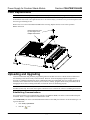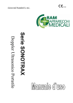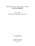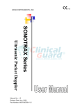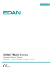
1
CSA-PWS10S-HUB
Introduction
The CSA-PWS10S-HUB power supply provides support for up to 10 Crestron® shades and features a built-in,
5-segment hub with network diagnostics capabilities. Local controls and indicators allow for easy testing of shades
without connecting to a control system. The CSA-PWS10S-HUB is convection cooled for silent operation and can
be surface mounted. It is also available pre-assembled in a CAEN-1X1 enclosure, model
CSA-PWS10S-HUB-CAEN-1X1, which can be surface mounted or recessed in a wall.
CSA-PWS10S-HUB Specifications
SPECIFICATION
DETAILS
Load Rating
Total Shades Supported
Provides power for up to (10) Crestron shades, each homerun to the power
supply
Output
24 Vdc
50 W per output LPS
350 W total continuous load
425 W for 2 minute on 2 minute off discontinuous shade load
Load Protection
(10) Self resetting thermal fuses and (10) 4 A time lag fuses, Littelfuse JDYX2
0213 004 MXP (5 x 20 mm, 250 V, 4 A, time lag, cartridge) provided for each
50 W segment, (1) of each per output
Power Requirements
120–240 Vac, 50/60 Hz;
5 A maximum
Environmental
Installation Location
Indoor use only
Temperature
32º to 104ºF (0º to 40ºC)
Humidity
10% to 90% RH (non-condensing)
Enclosure
CSA-PWS10S-HUB
CSA-PWS10S-HUBCAEN-1X1
Dimensions
CSA-PWS10S-HUB
Height
Width
Depth
CSA-PWS10S-HUBCAEN-1X1
Height
Width
Depth
Weight
CSA-PWS10S-HUB
CSA-PWS10S-HUBCAEN1x1
Metal, gray, surface mount (indoor use only)
Includes CAEN-1X1, 16 gauge galvanized steel enclosure with vented gray steel
cover, surface mount or recessed in a wall (indoor use only)
7 9/16 in (194 mm)
12 15/16 in (330 mm)
2 11/16 in (68 mm)
16 9/16 in (421 mm)
16 1/8 in (409 mm)
4 7/16 in (113 mm)
5.6 lb (2.6 kg)
15.0 lb (6.8 kg)
(Continued on the following page)
Crestron Electronics, Inc.
15 Volvo Drive Rockleigh, NJ 07647
Tel: 888.CRESTRON
Fax: 201.767.7576
www.crestron.com
Installation Guide – DOC. 7438C
(2037987)
06.14
Specifications subject to
change without notice.
Crestron CSA-PWS10S-HUB
Power Supply for Crestron Shade Motors
CSA-PWS10S-HUB Specifications (Continued)
SPECIFICATION
Input Terminal
(CSA-PWS10S-HUB-CAEN1X1 only)
Line Power
CSA-PWS10S-HUB
CSA-PWS10S-HUBCAEN-1X1
®
DETAILS
18–10 AWG, 30 A, 600 V
(1) Attached input power cable (~10 in long (254 mm)) with inline IEC 60320 C14
main power inlet;
Mates with removable power cord (included)
(1) Attached input power cable (~10 in long (254 mm)) with inline IEC 60320 C14
main power inlet;
Connects to ac power source using grounded pigtail cable and terminal block
(both included)
Cresnet
(2) 4-pin 5 mm detachable terminal blocks (Cresnet connectors included);
Cresnet slave ports, paralleled;
Connect to Cresnet control network, power not supplied to these connections;
Cresnet power output ports with data pass-through;
In event of power failure the unit is auxiliary powered from this port to provide
status
A-E, 1-10
(10) 4-pin 5 mm detachable terminal blocks comprising (2) Cresnet ports per
each of (5) hub segments (Cresnet connectors included);
Each terminal bock provides 24 volts and 50 watts LPS
USB
(1) USB Type B female, USB computer console port
LEDs
PWR 1-10
(10) Green LEDs, indicate 24 V present at each corresponding output;
Indicates over current situation
NET A-E
(5) Amber LEDs, indicate Cresnet activity on each corresponding segment;
Indicates issues on the bus during diagnostic testing
NET HOST
(1) Amber LED, indicates activity on the Cresnet bus
MSG
(1) Red LED, indicates error messages and test mode
Push Buttons
MASTER UP
MASTER DOWN
TEST
RESET
(1) Push button, press and hold to raise all connected shades
(1) Push button, press and hold to lower all connected shades
(1) Push button, initiates diagnostic test
(1) Recessed push button, forces hardware reset
2 • Power Supply for Crestron Shade Motors: CSA-PWS10S-HUB
Installation Guide – DOC. 7438C
Crestron CSA-PWS10S-HUB
Power Supply for Crestron Shade Motors
Regulatory Compliance
Conformité Reglementaire
This product is Listed to applicable UL Standards
and requirements by Underwriters Laboratories Inc.
Ce produit est homologué selon les normes et les
exigences UL applicables par Underwriters
Laboratories Inc.
As of the date of manufacture, the CSA-PWS10S-HUB and CSA-PWS10S-HUB-CAEN-1X1 have been
tested and found to comply with specifications for CE marking.
Federal Communications Commission (FCC) Compliance Statement
These devices comply with part 15 of the FCC Rules. Operation is subject to the following conditions:
(1) These devices may not cause harmful interference and (2) these devices must accept any interference
received, including interference that may cause undesired operation.
CAUTION: Changes or modifications not expressly approved by the manufacturer responsible for
compliance could void the user’s authority to operate the equipment.
NOTE: This equipment has been tested and found to comply with the limits for a Class B digital device,
pursuant to part 15 of the FCC Rules. These limits are designed to provide reasonable protection against
harmful interference in a residential installation. This equipment generates, uses and can radiate radio
frequency energy and, if not installed and used in accordance with the instructions, may cause harmful
interference to radio communications. However, there is no guarantee that interference will not occur in a
particular installation. If this equipment does cause harmful interference to radio or television reception,
which can be determined by turning the equipment off and on, the user is encouraged to try to correct the
interference by one or more of the following measures:
•
Reorient or relocate the receiving antenna
•
Increase the separation between the equipment and receiver
•
Connect the equipment into an outlet on a circuit different from that to which the receiver is connected
•
Consult the dealer or an experienced radio/TV technician for help
Industry Canada (IC) Compliance Statement
Industrie Canada (IC) Déclaration de conformité
CAN ICES-3(B)/NMB-3(B)
Installation Guide – DOC. 7438C
Power Supply for Crestron Shade Motors: CSA-PWS10S-HUB • 3
Crestron CSA-PWS10S-HUB
Power Supply for Crestron Shade Motors
CSA-PWS10S-HUB-CAEN-1X1 Overall Dimensions (Top and Front Views)
1 1/4 in
1 1/2 in
5/8 in
(32 mm) (39 mm)
(16 mm)
15/16 in
(24 mm)
1 1/4 in
(32 mm)
5 11/16 in
(145 mm)
2 1/2 in
(64 mm)
1 5/16 in
(33 mm)
2 5/16 in
(58 mm)
1 1/4 in
(32 mm)
2 9/16 in
(65 mm)
(4x) Ø 1 3/4 in (45 mm)
Knockouts for 1 1/4 in
(32 mm) Conduit
16 9/16 in
(421 mm)
16 1/8 in
(409 mm)
4 • Power Supply for Crestron Shade Motors: CSA-PWS10S-HUB
Installation Guide – DOC. 7438C
Power Supply for Crestron Shade Motors
Crestron CSA-PWS10S-HUB
CSA-PWS10S-HUB-CAEN-1X1 Overall Dimensions (Bottom View)
2 1/2 in
(64 mm)
3 13/16 in
(97 mm)
(21x) Ø 7/8 in (23 mm)
Knockouts for 1/2 in
(13 mm) Conduit
1 1/4 in
(32 mm)
1 1/4 in
(32 mm)
11 1/4 in
(286 mm)
1 1/4 in
(32 mm) Typ.
5/8 in
(16 mm)
15/16 in
(24 mm)
14 3/8 in
(365 mm)
Installation Guide – DOC. 7438C
Power Supply for Crestron Shade Motors: CSA-PWS10S-HUB • 5
Crestron CSA-PWS10S-HUB
Power Supply for Crestron Shade Motors
CSA-PWS10S-HUB-CAEN-1X1 Overall Dimensions (Side View)
1 3/4 in
1 in
(45 mm)
(26 mm)
(8x) Ø~3/16 in (5 mm) Mounting Holes
for #8 Wood Screws (Not Supplied)
10 13/16 in
(275 mm)
8 in
(203 mm)
5 7/16 in
(138 mm)
15 13/16 in
(402 mm)
1 7/16 in
(36 mm)
2 1/2 in
(64 mm)
2 1/4 in
(58 mm)
4 1/4 in
(108 mm)
4 7/16 in
(113 mm)
6 • Power Supply for Crestron Shade Motors: CSA-PWS10S-HUB
Installation Guide – DOC. 7438C
Power Supply for Crestron Shade Motors
Crestron CSA-PWS10S-HUB
CSA-PWS10S-HUB-CAEN-1X1 Overall Dimensions (Front View, Cover Removed)
Cresnet connectors
are included.
2 1/4 in
(58 mm)
(4x) Ø~5/16 in (8 mm) Mounting Holes
10 7/8 in
for #8 Wood Screws and #8 Large
(276 mm)
Flat Washers (Not Supplied)
(4x) Ø5/8 in
(16 mm)
(4x) 7/16 in
(12 mm)
10 15/16 in
(277 mm)
CSA-PWS10S-HUB
ASSEMBLED IN COO
Cable Tie
Anchors
000 00
INPUT: 120-240
V~, 50/60 Hz
, 5A MAX
.
I.T.E
OUTPU
T: 24V , 350WCONTINUOUS
,
POWER SUPP
LY
41JC
425W. ON
2MIN
2MIN
. OFF LIMITEDTY
DUCYCLE.
50W MAX/OUTPUT LPS
PN 6506308
CSA-PWS10S-HUB- CAEN-1X1
ASSEMBLED IN COO
REPLACEMENT FUSE F1-F10
:
SNXXXXX
5 X 20 MM ,4A
250V~
TIME A
LG FUSE
000 00
INPUT: 120-240
V~, 50/60 Hz
, 5A MAX
.
I.T.E
OUTPU
T: 24V , 350WCONTINUOUS
,
POWER SUPP
LY
425W. ON
2MIN
2MIN
. OFF LIMITEDTY
DUCYCLE.
41JC
50W MAX/OUTPUT LPS
PN 6506320
SNXXXXX
2 3/4 in
(70 mm)
Barcode Label for
Power Supply
Barcode Label for
Entire Assembly
(4x) Ø 1 3/8 in
(35 mm)
Mounting Boss
9 7/8 in
(251 mm)
Installation Guide – DOC. 7438C
Power Supply for Crestron Shade Motors: CSA-PWS10S-HUB • 7
Crestron CSA-PWS10S-HUB
Power Supply for Crestron Shade Motors
CSA-PWS10S-HUB Overall Dimensions (Top, Front, and Bottom Views—Shown with Fuse Cover Removed)
1/4 in
(7 mm) Offset
2 1/4 in
(58 mm)
IEC, 3
Conductor
Male Cable,
Aprox. 10”
(254 mm)
Long
All Cresnet
connectors and
fuses are included.
12 3/8 in
(314 mm)
(4x) Ø3/16 in
(5 mm) Mounting
Holes for #8 Pan
6 in
Head Wood
(153 mm)
Screws
(Not Supplied)
7 9/16 in
(194 mm)
3 1/16 in
(79 mm)
2 7/16 in
(63 mm)
CSA-PWS10S-HUB
AS SEMBLED IN COO
PN 6506308
12 15/16 in
(330 mm)
1 1/8 in
(29 mm)
000 00
INPUT: 120-240
V~, 50/60 Hz
, 5A MAX
.
I.T.E
OUTPUT: 24V , 350WCONTINUOUS
,
POWER SUPP
LY
41JC
425W 2MIN
. ON 2MIN
. OFF LIMITED DU
TY CYCLE.
50W MAX/OUTPUT LPS
REPLACEMENT FUSE F1-F10
:
5 X 20 MM 4A
, 250V~
TIME LAG FUSE
12 3/8 in
(314 mm)
8 7/16 in
(215 mm)
SN XXXX X
Barcode Label
for Power Supply
9/16 in
(15 mm)
1/8 in
(4 mm)
5/16 in
(9 mm)
10 11/16 in
(273 mm)
2 9/16 in
(66 mm)
8 • Power Supply for Crestron Shade Motors: CSA-PWS10S-HUB
1 11/16 in
(44 mm)
2 11/16 in
(68 mm)
Installation Guide – DOC. 7438C
Power Supply for Crestron Shade Motors
Crestron CSA-PWS10S-HUB
CSA-PWS10S-HUB Overall Dimensions (Side View)
7 9/16 in
(194 mm)
7 7/16 in
(189 mm)
5/8 in
(16 mm)
13/16 in
(21 mm)
Installation
The enclosure must be installed by a licensed electrician in accordance with all national and local codes.
CAUTION: Double pole/neutral fusing implemented.
CAUTION: The CSA-PWS10S-HUB-CAEN-1X1 houses equipment that needs to be air-cooled. Therefore, mount
in a well-ventilated area. The ambient temperature range should be 32°F to 104°F (0°C to 40°C). The relative
humidity should range from 10% to 90% (non-condensing). Allow adequate clearance in front of the vented cover
for servicing and ventilation.
NOTE: The CSA-PWS10S-HUB-CAEN-1X1 is designed for surface mounting or flush mounting on a wall.
NOTE: The CSA-PWS10S-HUB is intended for surface mounting on a wall.
NOTE: Enclosure and power supply are intended for indoor use only.
NOTE: When flush mounting, 5/8 in (16 mm) drywall is preferred.
NOTE: Four keyholes are located within the enclosure and should be used if surface mounting.
Mounting the CSA-PWS10S-HUB-CAEN-1X1
For surface mounting, the enclosure must be mounted securely to building wall studs or at least 1/4 in (7 mm)
plywood using four #8 screws with four #8 large flat washers (not included) before operation. The enclosure cover
must be installed for normal use.
For flush mounting, the enclosure must be mounted securely to building wall studs using eight #8 screws (not
included) before operation. The enclosure cover must be installed for normal use.
Mounting the CSA-PWS10S-HUB
To surface mount the CSA-PWS10S-HUB, the power supply must be mounted securely to building wall studs or at
least 1/4 in (7 mm) plywood using four #8 pan head wood screws. Use the screw holes indicated in
“CSA-PWS10S-HUB Overall Dimensions” on page 8 to secure the power supply to the mounting surface.
Installation Guide – DOC. 7438C
Power Supply for Crestron Shade Motors: CSA-PWS10S-HUB • 9
Crestron CSA-PWS10S-HUB
Power Supply for Crestron Shade Motors
Wiring
Once the unit is properly secured to the mounting surface, the unit must be properly wired. Refer to the guidelines
below for details.
CAUTION: All power feeds must be protected by single pole listed circuit breaker or branch rated fuse no greater
than 20 A.
NOTE: Use copper conductors only—rated 75°C or better.
NOTE: All wiring must be installed in accordance with all local and national electrical codes.
NOTE: Four snap bushings are supplied. If required, insert the snap bushings into the knockouts at the bottom of
the enclosure to prevent damage to low voltage wiring.
The device must be mounted before operation.
Class 1 and Class 2 field wires must be kept separate. Refer to the following illustrations showing wiring details.
Areas for high voltage (Class 1) wiring are along the left side of the unit. The right side of the enclosure is reserved
for low voltage (Class 2) wiring.
NOTE: The installer must provide disconnect means within site of the enclosure.
NOTE: The CSA-PWS10S-HUB power cable is considered to be a disconnect means. For this reason the total
length of power cable from CSA-PWS10S-HUB to the outlet cannot exceed 14 feet (4.5 meters).
Class 1 Wiring Details
Power
From
120-240
Vac
Neutral, Line,
and Ground
Connections
Class 1
Wiring Only
Class 1 Wiring
WIRE
CONNECTION
COLOR
GND
Ground
Green with Yellow Stripe
NEUT
Neutral
White
LINE
Hot
Black
Class 2 Wiring Details
Class 2
Wiring Only
10 • Power Supply for Crestron Shade Motors: CSA-PWS10S-HUB
Installation Guide – DOC. 7438C
Power Supply for Crestron Shade Motors
Crestron CSA-PWS10S-HUB
NOTE: Always disconnect ac power to the CSA-PWS10S-HUB before connecting network devices.
Control System and Shade Wiring Details
To Additonal
From
Cresnet
CSA-PWS10S-HUB’s
Control
or Other Cresnet
System
Devices
To Shade 1
To Shade 2
To Shade 3
To Shade 4
To Shade 5
To Shade 6
To Shade 7
To Shade 8
To Shade 9
To Shade 10
The power supply connections 1–10 are powered by two separate power feeds that are isolated from each other—1,
3, 5, 7, and 9 are powered separately from 2, 4, 6, 8, and 10. If the 7.5 A continuous load rating is exceeded on either
feed, the power LEDs for that feed scroll down to indicate that the level of current can only be sustained for
2 minutes on, 2 minutes off limited duty cycles. The power draw should be lowered if continuous use is expected. If
this situation occurs, rearrange the loads between the two power feeds to evenly distribute the power draw.
The power supply connections 1–10 have LEDs that indicate the status of the feed. The power LED remains solid
when the circuit is functioning properly. The power LED extinguishes when there is no power present (blown fuse).
The power LED blinks rapidly when the power draw exceeds 9 A.
Maximum Wire Runs
The cable length between the motor and power supply is limited by voltage drop along the cable. The following
limits should be observed for reliable performance.
NOTE: Wiring must be home-run from the power supply to each shade motor.
Maximum total length of Cresnet® cable run on each hub segment is 3,000 ft (~915 m). Observe the following
maximum lengths for Cresnet cable between the power supply and shade:
•
Cresnet-P (Plenum Rated, 2x #18 Power, 2x #22 Twisted Data) 130 ft (~40 m)
•
Cresnet-NP (2x #18 Power, 2x #22 Twisted Data) 130 ft (~40 m)
•
Cresnet-HP-NP (2x #12 Power, 2x #22 Twisted Data) 500 ft (~153 m)
Installation Guide – DOC. 7438C
Power Supply for Crestron Shade Motors: CSA-PWS10S-HUB • 11
Crestron CSA-PWS10S-HUB
Power Supply for Crestron Shade Motors
Operation
Once the power supply is mounted, wired, and powered up, a diagnostic test of the device and wiring should be
performed. During the diagnostic test the power supply identifies connected shades and tests the wiring of the
connected shades.
Hold down the TEST button for 2 seconds to enter Test mode. The MSG LED blinks to indicate that the power
supply is in Test mode.
During Test mode, the LED for the associated connection blinks to indicate the status of the connected shade. The
LED blinks in a #-# format. The first # indicates the number of consecutive LED blinks, the dash represents a short
pause, and the second # indicates the second number of consecutive LED blinks. The pattern repeats until the error
is cleared or the TEST button is pressed. Refer to the following table for error definitions.
LED Blink Patterns for Test Mode
BLINK PATTERN
ERROR
1-1
Broken Wire – Y
1-2
Short 24 V to Y
1-3
Short GND to Y
2-1
Broken Wire – Z
2-2
Short 24 V to Z
2-3
Short GND to Z
3-1
Short Y to Z
3-2
Broken Wire – Y or Z
Solid
Off
No Error
No Devices Detected
NOTE: A short to 24 V may be reported as a short to GND on long cable runs.
NOTE: A false short Y to Z may be reported if a termination resistor is implemented on Cresnet. Cresnet does not
require termination resistors.
NOTE: Not all broken wire conditions can be detected. A broken wire can only be detected in situations where
there is intermittent communication.
The MSG LED also blinks to indicate an error situation on the device. The LED blinks using the same #-# format
described above. Refer to the following table for error definitions.
LED Blink Patterns for MSG LED
BLINK PATTERN
ERROR
1-1
Com Issue Master error occurs when the master branch is held low for
more than 10 character times.
1-2
Com Issue Branch error occurs when any non-master branch is held low
for more than 10 character times.
1-3
Com Issue Master and Branch error occurs when the master branch and
any non-master branch are held low for more than 10 character times.
2-2
Blown fuse(s)
Press and hold MASTER UP or MASTER DOWN to test all connected shades. After the button is pressed for
2 seconds the power supply disconnects from the control system (if connected) and sends a raise or lower command
to all connected shades. The MSG LED blinks to indicate that the power supply is sending the raise or lower
command to all connected shades.
NOTE: The control system stays disconnected for 10 seconds after the last MASTER UP or MASTER DOWN
button press.
12 • Power Supply for Crestron Shade Motors: CSA-PWS10S-HUB
Installation Guide – DOC. 7438C
Power Supply for Crestron Shade Motors
Crestron CSA-PWS10S-HUB
Fuse Replacement
CAUTION: For continued protection against risk of fire, replace only with the same type and rating of fuse.
Fuse status is indicated by the green power LED on each associated channel. If the green LED is not illuminated it
means that the fuse needs to be replaced. Fuses are to be serviced only by a trained service person and replaced with
the same type and rating of fuse.
Remove fuse cover from CSA-PWS10S-HUB before servicing. Replace the fuse cover before operation.
Remove Fuse Cover
Remove the fuse cover
by removing the two
Phillips head screws.
Uploading and Upgrading
Crestron recommends using the latest programming software and that each device contains the latest firmware to
take advantage of the most recently released features. However, before attempting to upload or upgrade it is
necessary to establish communication. Once communication has been established, files (for example, programs or
firmware) can be transferred to the control system (or device). Finally, program checks can be performed (such as
changing the device ID or creating an IP table) to ensure the device is functioning properly.
NOTE: Crestron software and any files on the website are for authorized Crestron dealers and Crestron Service
Providers (CSPs) only. New users must register to obtain access to certain areas of the site (including the FTP site).
Establishing Communications
Use Crestron Toolbox™ for communicating with the CSA-PWS10S-HUB; refer to the Crestron Toolbox help file
for details. There is a single method of communication: USB.
The COMPUTER port on the CSA-PWS10S-HUB connects to the USB port on the PC via the included Type A to
Type B USB cable:
1.
Click Tools | System Info.
2.
Click the
icon.
Installation Guide – DOC. 7438C
Power Supply for Crestron Shade Motors: CSA-PWS10S-HUB • 13
Crestron CSA-PWS10S-HUB
Power Supply for Crestron Shade Motors
3.
For Connection Type, select USB. When multiple USB devices are connected, identify the
CSA-PWS10S-HUB by entering “CSA-PWS10S-HUB” in the Model text box, the unit’s serial number in
the Serial text box, or the unit’s hostname (if known) in the Hostname text box.
4.
Click OK. Communications are confirmed when the device information is displayed.
Programs and Firmware
Program or firmware files may be distributed from programmers to installers or from Crestron to dealers. Firmware
upgrades are available from the Crestron website as new features are developed after product releases. One has the
option to upload programs via the programming software or to upload and upgrade via the Crestron Toolbox. For
details on uploading and upgrading, refer to the Crestron Studio™ help file, SIMPL Windows help file, or the
Crestron Toolbox help file.
Crestron Studio or SIMPL Windows
If a Crestron Studio (or SIMPL Windows) program is provided, it can be uploaded to the control system using
Crestron Studio (or SIMPL Windows) or Crestron Toolbox.
Firmware
Check the Crestron website to find the latest firmware. (New users must register to obtain access to certain areas of
the site, including the FTP site.)
Upgrade CSA-PWS10S-HUB firmware via Crestron Toolbox.
1.
Establish communication with the CSA-PWS10S-HUB and display the “System Info” window.
2.
Select Functions | Firmware… to upgrade the CSA-PWS10S-HUB firmware.
Program Checks
For Cresnet connections, using Crestron Toolbox, display the network device tree (Tools | Network Device Tree
View) to show all network devices connected to the control system. Right-click on the CSA-PWS10S-HUB to
display actions that can be performed on the CSA-PWS10S-HUB.
14 • Power Supply for Crestron Shade Motors: CSA-PWS10S-HUB
Installation Guide – DOC. 7438C
Power Supply for Crestron Shade Motors
Crestron CSA-PWS10S-HUB
Problem Solving
Use the Right Wire
To ensure optimum performance over the full range of the installation topology, use Crestron Certified Wire only.
Failure to do so may incur additional charges if support is required to identify performance deficiencies because of
using improper wire.
Calculate Power
CAUTION: Use only Crestron power supplies for Crestron equipment. Failure to do so could cause equipment
damage or void the Crestron warranty.
CAUTION: Provide sufficient power to the system. Insufficient power can lead to unpredictable results or damage
to the equipment. Use the Crestron Power Calculator to help calculate how much power is needed for the system
(www.crestron.com/calculators).
When calculating the length of wire for a particular Cresnet run, the wire gauge and the Cresnet power usage of each
network unit to be connected must be taken into consideration. Use Crestron Certified Wire only. The wire gauge
and the Cresnet power usage of the run should be used in the following equation to calculate the cable length value
on the equation’s left side.
Cable Length Equation
40,000
L<
RxP
Where: L = Length of run (or chain) in feet
R = 6 ohms (Crestron Certified Wire: 18AWG (0.75 mm2))
or 1.6 ohms (Cresnet HP: 12 AWG (4 mm2))
P = Cresnet power usage of entire run (or chain)
Make sure the cable length value is less than the value calculated on the right side of the equation. For example, a
Cresnet run using 18 AWG Crestron Certified Wire and drawing 20 watts should not have a length of run more than
333 feet (101 meters). If Cresnet HP is used for the same run, its length could extend to 1,250 feet (381 meters).
NOTE: All Crestron certified Cresnet wiring must consist of two twisted pairs. One twisted pair is the 24 and G
pair and the other twisted pair is the Y and Z pair.
Strip and Tin Wire
Strip the ends of the power supply wires carefully to avoid nicking the conductors. Twist together the ends of the
wires that share a pin on the network connector and tin the twisted connection. Apply solder only to the ends of the
twisted wires. Avoid tinning too far up the wires or the end becomes brittle. Insert the tinned connection into the
connector and tighten the retaining screw. Repeat the procedure for the other three conductors.
Further Inquiries
To locate specific information or resolve questions after reviewing this guide, contact Crestron's True Blue Support
at 1-888-CRESTRON [1-888-273-7876] or, for assistance within a particular geographic region, refer to the listing
of Crestron worldwide offices at www.crestron.com/offices.
To post a question about Crestron products, log onto Crestron’s Online Help at www.crestron.com/onlinehelp. Firsttime users must establish a user account to fully benefit from all available features.
Future Updates
As Crestron improves functions, adds new features, and extends the capabilities of the CSA-PWS10S-HUB and
CSA-PWS10S-HUB-CAEN-1X1, additional information may be made available as manual updates. These updates
are solely electronic and serve as intermediary supplements prior to the release of a complete technical
documentation revision.
Check the Crestron website periodically for manual update availability and its relevance. Updates are identified as
an “Addendum” in the Download column.
Installation Guide – DOC. 7438C
Power Supply for Crestron Shade Motors: CSA-PWS10S-HUB • 15
Crestron CSA-PWS10S-HUB
Power Supply for Crestron Shade Motors
Return and Warranty Policies
Merchandise Returns / Repair Service
1.
No merchandise may be returned for credit, exchange or service without prior authorization from Crestron.
To obtain warranty service for Crestron products, contact an authorized Crestron dealer. Only authorized
Crestron dealers may contact the factory and request an RMA (Return Merchandise Authorization) number.
Enclose a note specifying the nature of the problem, name and phone number of contact person, RMA
number and return address.
2.
Products may be returned for credit, exchange or service with a Crestron Return Merchandise
Authorization (RMA) number. Authorized returns must be shipped freight prepaid to Crestron,
6 Volvo Drive, Rockleigh, N.J. or its authorized subsidiaries, with RMA number clearly marked on the
outside of all cartons. Shipments arriving freight collect or without an RMA number shall be subject to
refusal. Crestron reserves the right in its sole and absolute discretion to charge a 15% restocking fee plus
shipping costs on any products returned with an RMA.
3.
Return freight charges following repair of items under warranty shall be paid by Crestron, shipping by
standard ground carrier. In the event repairs are found to be non-warranty, return freight costs shall be paid
by the purchaser.
Crestron Limited Warranty
Crestron Electronics, Inc. warrants its products to be free from manufacturing defects in materials and workmanship
under normal use for a period of three (3) years from the date of purchase from Crestron, with the following
exceptions: disk drives and any other moving or rotating mechanical parts, pan/tilt heads and power supplies are
covered for a period of one (1) year; touch screen display and overlay components are covered for 90 days; batteries
and incandescent lamps are not covered.
This warranty extends to products purchased directly from Crestron or an authorized Crestron dealer. Purchasers
should inquire of the dealer regarding the nature and extent of the dealer's warranty, if any.
Crestron shall not be liable to honor the terms of this warranty if the product has been used in any application other
than that for which it was intended or if it has been subjected to misuse, accidental damage, modification or
improper installation procedures. Furthermore, this warranty does not cover any product that has had the serial
number altered, defaced or removed.
This warranty shall be the sole and exclusive remedy to the original purchaser. In no event shall Crestron be liable
for incidental or consequential damages of any kind (property or economic damages inclusive) arising from the sale
or use of this equipment. Crestron is not liable for any claim made by a third party or made by the purchaser for a
third party.
Crestron shall, at its option, repair or replace any product found defective, without charge for parts or labor.
Repaired or replaced equipment and parts supplied under this warranty shall be covered only by the unexpired
portion of the warranty.
Except as expressly set forth in this warranty, Crestron makes no other warranties, expressed or implied, nor
authorizes any other party to offer any warranty, including any implied warranties of merchantability or fitness for a
particular purpose. Any implied warranties that may be imposed by law are limited to the terms of this limited
warranty. This warranty statement supersedes all previous warranties.
The specific patents that cover Crestron products are listed at patents.crestron.com.
Crestron, the Crestron logo, Cresnet, Crestron Studio, and Crestron Toolbox are either trademarks or registered trademarks of Crestron
Electronics, Inc. in the United States and/or other countries. UL and the UL logo are either trademarks or registered trademarks of Underwriters
Laboratories, Inc. in the United States and/or other countries. Other trademarks, registered trademarks, and trade names may be used in this
document to refer to either the entities claiming the marks and names or their products. Crestron disclaims any proprietary interest in the marks
and names of others. Crestron is not responsible for errors in typography or photography.
This document was written by the Technical Publications department at Crestron.
©2014 Crestron Electronics, Inc.
16 • Power Supply for Crestron Shade Motors: CSA-PWS10S-HUB
Installation Guide – DOC. 7438C