1
TM
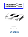
SAGEM F@st 240x
TM
SAGEM F@st 244x
Reference Manual
288 097 371-02
Edition of January 2007
Sagem Communication assiduously monitors technical developments and is constantly
seeking to improve its products in order to let its clients take full advantage of them. It therefore
reserves the right to modify its documentation accordingly without notice.
All brands mentioned in this guide are registered by their respective owners:
- SAGEM F@st™ is a registered brand of Sagem Communication.
- SAGEM F@st™ is a registered brand of Sagem Communication.
- WindowsTM and Internet ExplorerTM are registered brands of Microsoft Corporation.
- Apple® and Mac®OS are registered brands of Apple Computer Incorporation.
The purpose of the present reference manual is to give users the functions for operating and
managing the equipment. The only access level required (Administrator) is protected by a
password and allows one to access these functions in read and write mode for all the user and
network parameters (Login: admin; password: admin).
Configuration of the router by HTTP is described in detail (cf. section 5).
For better legibility of the reference manual, the term "router" will be used throughout the
document to designate SAGEM F@stTM 2400, SAGEM F@stTM 2404, SAGEM F@stTM 2440
and SAGEM F@stTM 2444 equipment.
Convention of symbols used in this manual
Warns you not to do an action, or commit a serious omission.
Gives you important information which you must take into account
SAGEM F@st™ 240x/244x Reference Manual - 288097371-02
Sagem Communication document. Reproduction and disclosure prohibited
Page 0-1
How should the document be used?
The present reference manual is organised into sections and annexes. These sections and
annexes cover the following subjects.
Section 1
Presentation of SAGEM F@stTM 240x and 244x equipment
Section 2
Presentation of SAGEM F@stTM 240x and 244x equipment
Section 3
Presentation of SAGEM F@stTM 2400/2440 equipment
Section 4
Presentation of SAGEM F@stTM 2404/2444 equipment
Section 5
Configuration of network parameters
Section 6
Configuration of the residential platform by HTTP
Section 7
Description of Internet access service
Section 8
Description of TV over ADSL service
Section 9
Updating the application
Annex A
Troubleshooting
Annex B
CE compliance declaration
Annex C
Environment
Annex D
Technical Characteristics
Annex E
Default configuration
Annex F
Glossary
Annex G
Connection technology
SAGEM F@st™ 240x/244x Reference Manual - 288097371-02
Page 0-2
Sagem Communication document. Reproduction and disclosure prohibited
Contents
Pages
Contents
0-3 to 0-6
1.
Introduction
1-1
1.1
Presentation
1-2
1.2
Composition of router pack
1-4
1.3
Minimum prerequisite
1-5
2.
Description and connection of router
2-1
2.1
Description
2.1.1 Connectors
2.1.2 LEDs
2.2
Connecting the ports of your router
2.2.1 Connecting to a power socket
2.2.2 Connection of the ADSL cable to the router
2.2.3 Connecting to your computer
2.2.3.1 Connection of the USB interface of your router to your computer
2.2.3.2 Connecting the Ethernet interface of your router to your computer
2.2.3.3 Connecting the Wi-Fi interface of your router to your computer
2.2.4 Connecting the Ethernet interface of your router to your TV decoder
2-2
2-3
2-5
2-7
2-8
2-9
2-10
2-10
2-11
2-12
2-13
2.3
Installation instructions
2-14
3.
Installing and configuring the SAGEM F@stTM 2400/2440 router
3-1
3.1
3.2
Installation by Wi-Fi interface
3.1.1 Wi-Fi USB adapter
3.1.2 Integrated Wi-Fi interface of your computer
3-4
3-4
3-8
Installing and configuring your Router with the network card of your
computer (Ethernet)
3-12
3.3
Installing and configuring your Router in the USB port of your computer
3-16
3.4
Installing and configuring an additional computer
3-20
4.
Installing and configuring the SAGEM F@stTM 2404/2444 router
4-1
4.1
Installation by Wi-Fi interface
4.1.1 Wi-Fi USB adapter
4.1.2 Integrated Wi-Fi interface of your computer
4-4
4-4
4-8
SAGEM F@st™ 240x/244x Reference Manual - 288097371-02
Sagem Communication document. Reproduction and disclosure prohibited
Page 0-3
4.2
Installing and configuring your Router with the network card of your
computer (Ethernet)
4-12
4.3
Installing and configuring an additional computer
4-16
5.
Configuration of network parameters
5-1
6.
Information / Configuration
6-1
6.1
Accessing the welcome screen
6-2
6.2
Recommendations
6-4
6.3
ADSL connection status
6-5
6.4
Display frame
6-5
6.5
6.6
Status
6.5.1 Summary
6.5.2 Diagnostics
Internet Connection
6-6
6-6
6-7
6-9
6.7
Wireless
6.7.1 Basic
6.7.1.1 Wireless - Basic
6.7.1.2 Quick Wireless - Security - Configuration
6.7.2 Security
6.7.2.1 Network Authentication
6.7.3 MAC Filter
6.7.4 Advanced
6.7.5 Quality of Service
6-10
6-10
6-11
6-12
6-15
6-17
6-33
6-35
6-39
6.8
NAT
6.8.1 Port forwarding
6.8.2 Port Triggering
6.8.3 DMZ Host
6.8.4 ALG
6-42
6-42
6-47
6-50
6-51
6.9
Advanced Setup
6.9.1 WAN
6.9.2 LAN
6.9.3 Security
6.9.3.1 Outgoing
6.9.3.2 Incoming
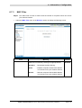
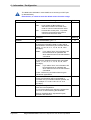
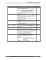
6.9.4 Quality of Service
6.9.4.1 Add
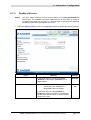
6.9.5 Routing
6.9.5.1 Default Gateway
6.9.5.2 Static Route
6.9.5.3 RIP
6.9.6 DNS
6.9.7 DSL
6.9.8 Port Mapping
6-52
6-52
6-74
6-76
6-76
6-78
6-81
6-84
6-89
6-89
6-90
6-92
6-94
6-95
6-98
SAGEM F@st™ 240x/244x Reference Manual - 288097371-02
Page 0-4
Sagem Communication document. Reproduction and disclosure prohibited
6.9.9 Certificate
6.9.9.1 Local
6.9.9.2 Trusted CA
6-103
6-103
6-106
6.10 Advanced Status
6.10.1 WAN
6.10.2 Statistics
6.10.2.1 LAN
6.10.2.2 WAN
6.10.2.3 ATM
6.10.2.4 ADSL
6.10.3 Route
6.10.4 ARP
6.10.5 DHCP
6.10.6 Station Info
6-108
6-108
6-109
6-109
6-110
6-111
6-112
6-114
6-115
6-116
6-117
6.11 Management
6.11.1 Settings
6.11.1.1 Backup
6.11.1.2 Update
6.11.1.3 Restore Default
6.11.2 System Log
6.11.3 TR-069 Client
6.11.4 Internet Time
6.11.5 Access Control
6.11.5.1 Services
6.11.5.2 IP Address
6.11.5.3 Passwords
6.11.6 Update Software
6.11.7 Save/Reboot
6-118
6-118
6-119
6-121
6-122
6-123
6-128
6-130
6-132
6-132
6-133
6-135
6-136
6-137
7.
Internet access service
7-1
7.1
Introduction
7-2
7.2
Connection for Internet access
7-3
8.
TV over ADSL service
8-1
8.1
Introduction
8-2
8.2
Access to the optional TV over ADSL service
8-2
9.
Updating the application
9-1
A.
Annex A - Troubleshooting
A-1
A.1 Checking the attribution of an IP address
A.1.1 In Windows
A.1.2 On a Mac (for example MacOS X)
A-2
A-2
A-2
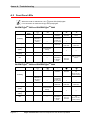
A.2
Front Face LEDs
A-4
A.3
Supervising your router
A-5
A.4
"Diagnostics" tool
A-6
SAGEM F@st™ 240x/244x Reference Manual - 288097371-02
Sagem Communication document. Reproduction and disclosure prohibited
Page 0-5
A.5 Interpreting the LEDs
A.5.1 The "ADSL" LED blinks slowly
A.5.2 "Wi-Fi" LED off
A.5.3 All LEDs are off
A-8
A-8
A-8
A-8
A.6
Reinitialising your router
A-9
A.7
Re-establishing the factory configuration
A-9
A.8
Offline mode
A-10
B.
Annex B - Warnings for safety
B-1
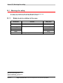
B.1 Warnings for safety
B.1.1 Safety levels in relation to the case
B-2
B-2
B.2
CE compliance declaration
B-3
C.
Annex C - Environment
C-1
C.1
Directive E 2002/96/CE
D.
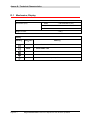
Annex D - Technical Characteristics
D.1
Mechanics; Display
D-2
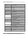
D.2
Characteristics of the different interfaces
D-3
D.3
Environmental characteristics
D-5
D.4
Application and protocols
D-6
E.
Annex E - Default configuration
E-1
E.1
Default username and password
E-2
E.2
Default configuration for the local network(LAN)
E-2
E.3
Default configuration for the local wireless network (WLAN)
E-3
E.4
Default configuration for the remote network (WAN)
E-3
F.
Annex F - Glossary
F-1
G.
Annex G - Connector Technology
G-1
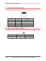
G.1
Pinouts of the "LINE" connector
G-2
G.2
Pinouts of the "ADSL" connector
G-2
G.3
Pinouts of the "ETH", "ETH1" to "ETH4" connectors
G-3
G.4
Pinouts of the "ADSL" connector
G-4
SAGEM F@st™ 240x/244x Reference Manual - 288097371-02
Page 0-6
Sagem Communication document. Reproduction and disclosure prohibited
C-2
D-1
1. Introduction
This section covers
¾
presentation of the SAGEM F@stTM 240x and
SAGEM F@stTM 244x ranges
§ 1.1
¾
composition of the packaging
§ 1.2
¾
required hardware and software
§ 1.3
SAGEM F@st™ 240x/244x Reference Manual - 288097371-02
Sagem Communication document. Reproduction and disclosure prohibited
Page 1-1
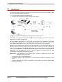
1 - Introduction
1.1
Presentation
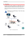
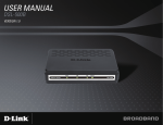
The present reference manual is dedicated to the SAGEM F@stTM 240x and
SAGEM F@stTM 244x product ranges. These products are routers which give users, via an
ADSL/ADSL2/ ADSL2+ network, broadband Internet access from their computer or their games
console by various Ethernet (10 or 100 BASE-T), USB or Wi-Fi (IEEE 802.11g) interfaces.
Using these wire interfaces, this router enables you both to surf the Internet and to watch
television. It also lets you telephone over the Internet from an IP SIP telephone linked by Wi-Fi
to your router.
SAGEM F@stTM 240x and SAGEM F@stTM 244x products adapt the ADSL
function respectively for POTS (UIT G.992.1/3/5 - Annex A) and for ISDN
(UIT G.992.1/3/5 - Annex B).
Figure 1.1 - Supervising your router
SAGEM F@st™ 240x/244x Reference Manual - 288097371-02
Page 1-2
Sagem Communication document. Reproduction and disclosure prohibited
1 - Introduction
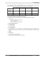
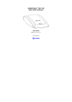
The SAGEM F@stTM 240x and SAGEM F@stTM 244x router product ranges contain the four
items of equipment, the main features of which are shown in the table below:
TM
SAGEM F@st
ADSL on POTS
(IUT 992.1
Annex A)
TM
240x SAGEM F@st
X
ADSL on POTS
(IUT 992.1
Annex A)
TM
240x SAGEM F@st
TM
240x SAGEM F@st
240x
X
X
X
10/100B-T ports
1
1
4
4
USB port
1
1
0
0
Its principal characteristics and functions are as follows:
¾
High-performance secure Bridge/Router with ADSL/ADSL2/ADSL2+ interface,
¾
User access:
•
1 to 4 x 10/100BT Ethernet port(s),
•
1 USB1.1 Slave port,
•
1 Wi-Fi port (802.11b/g) by mini-PCI,
¾
DHCP Client/Server/Relay,
¾
Server/DNS Relay,
¾
FTP Client/Server,
¾
TFTP Client/Server,
¾
HTTP Client/Server,
¾
NAT/PAT router - FTP Compatibility, IRC, Net2Phone, Netbios, DNS, Netmeeting, SIP,
VPN passthrough (IPSec, IKE, PPTP, L2TP), CUSeeMe, RealAudio, Microsoft IM and
others,
¾
Firewall,
¾
Spanning tree,
¾
HTTP server for easy configuration,
¾
Manual update of the application version locally.
SAGEM F@st™ 240x/244x Reference Manual - 288097371-02
Sagem Communication document. Reproduction and disclosure prohibited
Page 1-3
1 - Introduction
1.2
Composition of router pack
The router is supplied in a pack the composition of which changes according to the type of
equipment
(SAGEM F@stTM 2400,
SAGEM F@stTM 2440,
SAGEM F@stTM 2404
or
TM
SAGEM F@st 2444):
As an example, please find below the "pack" chosen for the SAGEM F@stTM 2400 router, i.e.:
¾ 1 SAGEM F@stTM 2400,
¾ 1 mains adapter unit,
¾ 1 ADSL RJ11/RJ11 FDT line cord (length = 3 m),
¾ 1 Ethernet RJ45/RJ45 linking cord (length = 1.75 m),
¾ 1 USB Type A male/Type B male cable (length = 1.5 m),
¾ 1 USB Wi-Fi key,
¾ 1 USB Type A male/Type A female cable (SAGEM F@stTM 2400),
¾ 1 Quick Installation Guide,
¾ 1 Installation CD-ROM,
¾ microfilter(s) (optional),
¾ 1 filter/splitter (optional),.
SAGEM F@st™ 240x/244x Reference Manual - 288097371-02
Page 1-4
Sagem Communication document. Reproduction and disclosure prohibited
1 - Introduction
The CD ROM contains:
•
the application for installing the USB interface.
•
the present Reference Manual (SAGEM F@st™ 24xx) in PDF format file.
•
the CE declaration of the chosen router.
Incomplete or damaged supply. If on its receipt the equipment is damaged or
incomplete, contact the Supplier of your router.
1.3
Minimum prerequisite
Using a router requires at minimum:
¾
a computer equipped:
•
with a Wi-Fi 802.11b/g interface,
or
•
a type A USB interface
or
•
¾
an Ethernet interface (10BASE-T or 10/100BASE-T),
a WEB browser (Internet Explorer version 5 or higher recommended).
The minimum configuration of your computer must be:
¾
for Windows: Pentium II, 400 MHz, RAM: 128 MB,
¾
for MacOS: Power PC G3, 233 MHz, RAM: 128 MB,
¾
a monitor of minimum resolution: 1024 x 768.
If you wish to use the Wi-Fi function (standard IEEE 802.11b/g), you must acquire the Wi-Fi
Standard pack (see annex G for use of Wi-Fi).
Before installing the router, we advise you to uninstall any modem or other router
(for example, an ADSL router).
SAGEM F@st™ 240x/244x Reference Manual - 288097371-02
Sagem Communication document. Reproduction and disclosure prohibited
Page 1-5
1 - Introduction
SAGEM F@st™ 240x/244x Reference Manual - 288097371-02
Page 1-6
Sagem Communication document. Reproduction and disclosure prohibited
2. Description and connection
of router
This section covers
¾
the description of your router
§ 2.1
¾
connecting the ports of your router
§ 2.2
¾
connecting to a power socket
§ 2.2.1
¾
connecting the line cable
§ 2.2.2
¾
connecting your computer
§ 2.2.3
¾
the TV connection
§ 2.2.4
¾
installation instructions
§ 2.3
SAGEM F@st™ 240x/244x Reference Manual - 288097371-02
Sagem Communication document. Reproduction and disclosure prohibited
Page 2-1
2 - Description and connection of router
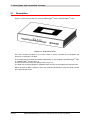
2.1
Description
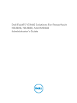
Figure 2.1 gives an overview of a router (SAGEM F@stTM 240x or SAGEM F@stTM 244x).
Figure 2.1 - Overview of case
This case consists principally of a lid and a base in which a printed circuit equipped with
electronic components is located.
The components of the base are different depending on the equipment (SAGEM F@stTM 24x0
or SAGEM F@stTM 24x4)(cf.§ 2.1.1)
The front face of the lid has five display LEDs (cf.§ 2.1.2).
The base has the LEDs ideograms, SAGEM's mark and logo or the operator's marking as well.
Below the base a label is glued on which the product's identification code, the series number
and a barcode are shown.
SAGEM F@st™ 240x/244x Reference Manual - 288097371-02
Page 2-2
Sagem Communication document. Reproduction and disclosure prohibited
2 - Description and connection of your router
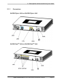
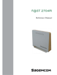
2.1.1
Connectors
SAGEM F@stTM 2400 and SAGEM F@stTM 2440
SAGEM F@stTM 2404 and SAGEM F@stTM 2444
SAGEM F@st™ 240x/244x Reference Manual - 288097371-02
Sagem Communication document. Reproduction and disclosure prohibited
Page 2-3
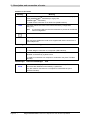
2 - Description and connection of router
Common to all routers
Marking
LINE
Meaning
RJ11 connector - 6 pts. This connector is identified on the base by a grey
frame (SAGEM F@stTM 2400/2440) or a grey line
(SAGEM F@stTM 2404/2444).
It is used for the connection to an ADSL line (WAN interface).
REG
This button allows the router to be reset to the factory configuration
(see § A.7).
Note:
It is set back relative to the other elements to prevent an accidental
loss of configuration.
On/Off switch.
PWR
Miniature jack fixed connector.
This connector enables the router to be supplied with direct current from a
mains adapter unit.
SAGEM F@stTM 2400 and SAGEM F@stTM 2440
USB
This connector is identified on the base by a blue frame.
It is used only for connection to a computer (USB interface).
ETH
RJ45 connector - 8 pts (10/100BASE-T Ethernet Interface). This connector is
identified on the base by a yellow frame.
It is used for connection to a computer or a television set (via a TV/Video
Decoder).
SAGEM F@stTM 2404 and SAGEM F@stTM 2444
ETH1 to
ETH4
RJ45 connectors - 8 pts (10/100BASE-T Ethernet Interface). These
connectors are identified on the base by a yellow line.
They are used for connection to a computer or a television set (via a
TV/Video Decoder).
SAGEM F@st™ 240x/244x Reference Manual - 288097371-02
Page 2-4
Sagem Communication document. Reproduction and disclosure prohibited
2 - Description and connection of your router
2.1.2
LEDs
The different LEDs of the figure below are described in the following table:
Common to all routers
Marking
Abbreviation
PWR
ADSL
Internet
WLAN
Meaning
Alarm LED (Green/Red bicolour LED):
•
lits green if power is present,
•
lits red in the case of failure detected at the time of starting,
•
goes out if there is no power.
Green ADSL LED:
•
blinks slowly when the ADSL is not detected,
•
blinks quickly when the ADSL line is being synchronised,
•
stays lit when the ADSL line is detected.
Internet connection LED (Green/Red bicolour LED):
•
remains lit when the "PPP" connection is established or when the
router is in "Bridge" mode,
•
lits green when the "PPP" connection is established,
•
lits red when the "PPP" connection is not established,
•
blinks when traffic is detected on the WAN interface.
Green ADSL LED:
This LED indicates activation/deactivation of Wi-Fi mode.
•
This LED is off when the "Wi-Fi" interface is deactivated.
•
This LED blinks in the presence of traffic on the WLAN interface.
•
This LED is lit when the "Wi-Fi" interface is activated.
SAGEM F@st™ 240x/244x Reference Manual - 288097371-02
Sagem Communication document. Reproduction and disclosure prohibited
Page 2-5
2 - Description and connection of router
SAGEM F@stTM 2400 and SAGEM F@stTM 2440
Marking
Abbreviation
LAN
Meaning
Green local network (LAN) LED:
This LED indicates data traffic between the router and the different
USB and Ethernet (ETH) interfaces.
•
This LED is off if no interface (Ethernet or USB) is detected.
•
This LED blinks when traffic is detected on one of the interfaces.
•
This LED is lit when an Ethernet or USB interface is detected and
if no traffic is detected.
SAGEM F@stTM 2404 and SAGEM F@stTM 2444
Marking
Abbreviation
LAN
Meaning
Green local network (LAN) LED:
This LED indicates data traffic between the router and the different
USB and Ethernet (ETH) interfaces.
•
This LED is off if no Ethernet interface (ETH1, ETH2, ETH3 or
ETH4) is detected.
•
This LED blinks when traffic is detected on one of the interfaces.
•
This LED is lit if at least one Ethernet interface (ETH1, ETH2,
ETH3 or ETH4) is detected and if no traffic is detected.
SAGEM F@st™ 240x/244x Reference Manual - 288097371-02
Page 2-6
Sagem Communication document. Reproduction and disclosure prohibited
2 - Description and connection of your router
2.2
Connecting the ports of your router
Figure 2.2 - Interconnection of ports of SAGEM F@stTM 2400 et 2440
Figure 2.3 - Interconnection of ports of SAGEM F@stTM 2404 et 2444
SAGEM F@st™ 240x/244x Reference Manual - 288097371-02
Sagem Communication document. Reproduction and disclosure prohibited
Page 2-7
2 - Description and connection of router
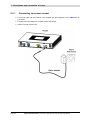
2.2.1
Connecting to a power socket
¾
First connect the end of the mains cord, supplied with the equipment, to the PWR base of
your router.
¾
Connect the mains adapter to a nearby mains wall socket.
¾
Set the "On/Off" switch to On.
SAGEM F@st™ 240x/244x Reference Manual - 288097371-02
Page 2-8
Sagem Communication document. Reproduction and disclosure prohibited
2 - Description and connection of your router
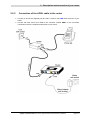
2.2.2
Connection of the ADSL cable to the router
¾
Connect an end of the supplied grey RJ11/RJ11 cable to the LINE fixed connector of your
router.
¾
Connect the other end of this cable to the connector marked ADSL on the micro-filter
connected to the RJ11 telephone wall socket of your home.
SAGEM F@st™ 240x/244x Reference Manual - 288097371-02
Sagem Communication document. Reproduction and disclosure prohibited
Page 2-9
2 - Description and connection of router
2.2.3
Connecting to your computer
Three connections may have to be made:
¾
Connection of the USB interface of your router to your computer.
¾
Connection of the Ethernet interface of your router to your computer.
¾
Connection of the WLAN (Wi-Fi) interface to your computer.
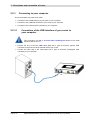
2.2.3.1
Connection of the USB interface of your router to
your computer
This connection is made in all cases after installing the drivers of the USB
interface (see section 3).
¾
Connect the end of the blue USB cable fitted with a type B connector (square fixed
connector) to the fixed connector marked USB of your router,
¾
Connect the other end of the cable fitted with a type A connector (rectangular fixed
connector) to your computer.
SAGEM F@st™ 240x/244x Reference Manual - 288097371-02
Page 2-10
Sagem Communication document. Reproduction and disclosure prohibited
2 - Description and connection of your router
2.2.3.2
Connecting the Ethernet interface of your router to
your computer
¾
Connect the end of the yellow Ethernet cable (RJ45/RJ45) supplied in the pack to the
Ethernet fixed connector (either marked ETH in the case of the SAGEM F@stTM2400, or
marked ETH1, ETH2, ETH3 or ETH4 in the case of the SAGEM F@stTM 2404 and
SAGEM F@stTM 2444) of your router,
¾
Connect the other end of the cable to your computer.
SAGEM F@st™ 240x/244x Reference Manual - 288097371-02
Sagem Communication document. Reproduction and disclosure prohibited
Page 2-11
2 - Description and connection of router
2.2.3.3
Connecting the Wi-Fi interface of your router to
your computer
Wireless linking enables the router to be connected to your computer.
To make this connection you must have a Wi-Fi pack (option). This pack comprises the
following elements:
•
1 Wi-Fi 188470912 key (Dongle) in an anti-static plastic bag,
•
1 USB adapter cord for Dongle,
•
1 CD-ROM.
Inserting a USB Wi-Fi key in your computer
This key is connected to your computer only during installation of the Wi-Fi drivers (standard
802.11b/g)(see § 3.1.1).
You can also use the wifi adapter incorporated in your computer.
SAGEM F@st™ 240x/244x Reference Manual - 288097371-02
Page 2-12
Sagem Communication document. Reproduction and disclosure prohibited
2 - Description and connection of your router
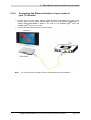
2.2.4
Connecting the Ethernet interface of your router to
your TV decoder
¾
Connect the end of the yellow Ethernet cable (RJ45/RJ45) supplied in the pack to the
Ethernet fixed connector (either marked ETH in the case of the SAGEM F@stTM2400, or
marked ETH1, ETH2, ETH3 or ETH4 in the case of the SAGEM F@stTM 2404 and
SAGEM F@stTM 2444) of your router
¾
Connect the other end of the cable to a TV decoder.
Note:
For connection to the decoder, refer to the manufacturer's documentation.
SAGEM F@st™ 240x/244x Reference Manual - 288097371-02
Sagem Communication document. Reproduction and disclosure prohibited
Page 2-13
2 - Description and connection of router
2.3
Installation instructions
Environment
¾
The router must be installed and used inside a building.
¾
The ambient temperature must not exceed 45°C.
¾
The router must not be exposed to direct strong sunlight nor to an intense heat source.
¾
The router must not be placed in an environment subject to vapour condensation.
¾
The router must not be exposed to water projections.
¾
The router unit must not be covered.
Power source
¾
Use a network socket with easy access, which is close to the equipment. The power cord is
2 m in length.
¾
Arrange the power cord so as to prevent any accidental power cutoff of the router.
¾
The router is designed to be connected to a TT or TN type power network.
¾
The router is not designed to be connected to an electrical installation with an IT type
diagram (neutral connected to earth through an impedance).
¾
Protection against short circuits and inter-phase leakages, neutral and earth must be made
by the building's electrical installation. The power circuit of this equipment must be fitted
with a 16 A protection against power surges, and with a differential protection.
Maintenance
¾
It is prohibited to open the case. Only qualified personnel approved by your supplier may do
so.
¾
Do not use liquid or spray cleaning agents.
SAGEM F@st™ 240x/244x Reference Manual - 288097371-02
Page 2-14
Sagem Communication document. Reproduction and disclosure prohibited
3. Installing and configuring the
SAGEM F@stTM 2400/2440 router
This section covers
¾
installing your Router with the Wi-Fi USB adapter.
§ 3.1.1
¾
installing your Router with the integrated Wi-Fi component § 3.1.2
of your computer.
¾
installing your Router with the network card of your
computer (Ethernet).
§ 3.2
¾
installing your Router in the USB port of your computer.
§ 3.3
¾
installing an additional computer.
§ 3.4
SAGEM F@st™ 240x/244x Reference Manual - 288097371-02
Sagem Communication document. Reproduction and disclosure prohibited
Page 3-1
3 - Installing and configuring the SAGEM F@stTM 2400/2440 router
Your router can be installed and configured with the following interfaces:
¾
Wi-Fi (cf. § 3.1),
¾
Ethernet (ETH)(cf. § 3.2),
¾
USB (cf. § 3.3).
Before installing your SAGEM F@st™ SAGEM F@stTM 2400/2440 router, we
recommend you uninstall every ADSL router.
The installation procedure described below was undertaken in
Windows® XP. Installation in other Windows operating
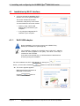
systems® (98, ME and 2000) can be slightly different.
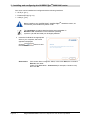
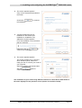
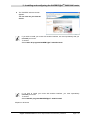
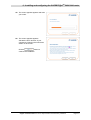
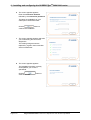
1
Insert the CD-ROM in the appropriate
driver of your computer; the screen
opposite is displayed.
Click the
the installation.
Observation:
button to start
If this screen does not appear: Select, in the menu Start, the command
Execute, then enter:
<letter of CD-ROM drive> :\autorun.exe (for example, e:\autorun.exe)
then click OK.
SAGEM F@st™ 240x/244x Reference Manual - 288097371-02
Page 3-2
Sagem Communication document. Reproduction and disclosure prohibited
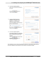
3 - Installing and configuring the SAGEM F@stTM 2400/2440 router
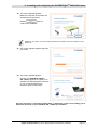
2
The screen opposite appears.
Carry out the operations described on
the screen.
Click button
the installation.
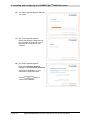
3
to continue
A screen enabling the type of
installation to the chosen (first
installation or installation of an
additional computer) appears.
For a first installation, we recommend
that you check the
button then click on
continue the installation.
4
to
The screen opposite appears.
This screen enables you to choose to
which interface (Wi-Fi, Ethernet or
USB) you wish to connect your router to
your computer.
Select the interface required and then
click the
button to
continue the installation.
The installation of your router using different interfaces is described in detail below in
the order displayed on the previous screen (choice of connection mode).
SAGEM F@st™ 240x/244x Reference Manual - 288097371-02
Sagem Communication document. Reproduction and disclosure prohibited
Page 3-3
3 - Installing and configuring the SAGEM F@stTM 2400/2440 router
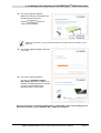
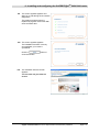
3.1
Installation by Wi-Fi interface
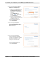
1
You have selected the wireless (Wi-Fi)
interface; the screen opposite appears.
This screen enables the wireless
connection mode (Wi-Fi) to be chosen.
You are offered two connection modes:
3.1.1
•
either by using a Wi-Fi USB
adapter (key) connected to your
computer,
•
or by using the integrated Wi-Fi
interface of your computer.
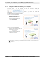
Wi-Fi USB adapter
During installation you must not connect your USB Wi-Fi key
before you are asked for it (see stage 5a).
The installation manages the SAGEM brand USB Wi-Fi adapters
model XG 760N (supplied in the pack). The driver of this key is
contained on the CD-ROM.
If you wish to use another key, you will be asked to install the driver
of this key during the installation.
You have selected the Wi-Fi USB adapter by clicking the
button ; you have then clicked the
button to continue the installation.
2a The screen opposite appears.
Make the electrical connection as
described on the screen.
Click the
button to
continue the installation.
SAGEM F@st™ 240x/244x Reference Manual - 288097371-02
Page 3-4
Sagem Communication document. Reproduction and disclosure prohibited
3 - Installing and configuring the SAGEM F@stTM 2400/2440 router
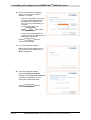
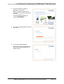
3a The screen opposite appears.
Make the connection of the ADSL line
as described on the screen.
Click the
button to
continue the installation.
Whatever your choice, you must make the electrical connection and the connection to the
ADSL line.
4a The screen opposite appears and asks
you to wait.
5a The screen opposite appears.
Connect your USB Wi-Fi adapter
XG - 760N (supplied in the pack) to an
available corresponding fixed connector
on your computer following the
illustration given on the screen.
As soon as the key is connected "Please wait" is displayed on the screen, asking you to
wait while the driver of your USB Wi-Fi XG - 760N key is installed.
SAGEM F@st™ 240x/244x Reference Manual - 288097371-02
Sagem Communication document. Reproduction and disclosure prohibited
Page 3-5
3 - Installing and configuring the SAGEM F@stTM 2400/2440 router
6a The screen opposite then appears,
asking you to configure the Wi-Fi
interface. To do this:
•
Select in the scrollbox the name of
the router (SSID indicated on the
label glued on to the box) with
which you wish to associate your
computer.
In the contrary case, click
button
, then select
from the scrollbox.
•
Enter the 26-character WEP key
(128 bit encryption) indicated on the
label glued on to the box.
Click the
button to
continue the installation.
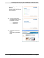
7a The screen opposite appears.
Please wait during the diagnostics of
the connection to the Router via the
Wi-Fi USB adapter.
8a The screen opposite appears.
Enter the connection identifier
followed by the connection password.
The latter are available from your
subscription confirmation letter.
button to
Click the
continue the installation.
SAGEM F@st™ 240x/244x Reference Manual - 288097371-02
Page 3-6
Sagem Communication document. Reproduction and disclosure prohibited
3 - Installing and configuring the SAGEM F@stTM 2400/2440 router
9a The screen opposite appears and asks
you to wait during the successive
diagnostics.
The rotating orange arrows are
replaced by a green check mark after
each successful test.
10a The screen opposite appears.
The installation has been correctly
accomplished; your router is
operational.
Click the
close the window.
button to
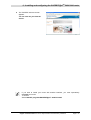
11a The "SAGEM" welcome screen
appears.
You can now use your Internet
access.
SAGEM F@st™ 240x/244x Reference Manual - 288097371-02
Sagem Communication document. Reproduction and disclosure prohibited
Page 3-7
3 - Installing and configuring the SAGEM F@stTM 2400/2440 router
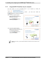
3.1.2
Integrated Wi-Fi interface of your computer
You have chosen to use the integrated Wi-Fi of your computer by clicking the
button
;
you
have
then
clicked
the
button to continue the installation.
2b The screen opposite appears.
Make the electrical connection as
described on the screen.
Click the
button to
continue the installation.
3b The screen opposite appears.
Make the connection of the ADSL line
as described on the screen.
Click the
button to
continue the installation.
Whatever your choice, you must make the electrical connection and the connection to the
ADSL line.
SAGEM F@st™ 240x/244x Reference Manual - 288097371-02
Page 3-8
Sagem Communication document. Reproduction and disclosure prohibited
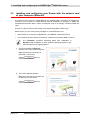
3 - Installing and configuring the SAGEM F@stTM 2400/2440 router
4b The screen opposite appears and asks
you to wait.
5b The screen opposite appears.
Activate the Wi-Fi function of your
computer by following the instructions
shown on the screen.
Click the
button to
continue the installation.
SAGEM F@st™ 240x/244x Reference Manual - 288097371-02
Sagem Communication document. Reproduction and disclosure prohibited
Page 3-9
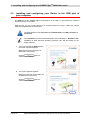
3 - Installing and configuring the SAGEM F@stTM 2400/2440 router
6b The screen opposite appears and asks
you to wait.
7b The screen opposite appears.
Please wait during the diagnostics of
the connection to the Router via the
integrated Wi-Fi interface of your
computer.
8b The screen opposite appears.
Enter the connection identifier
followed by the connection password.
The latter are available from your
subscription confirmation letter.
button to
Click the
continue the installation.
SAGEM F@st™ 240x/244x Reference Manual - 288097371-02
Page 3-10
Sagem Communication document. Reproduction and disclosure prohibited
3 - Installing and configuring the SAGEM F@stTM 2400/2440 router
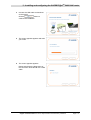
9b
The screen opposite appears and
asks you to wait during the successive
diagnostics.
The rotating orange arrows are
replaced by a green check mark after
each successful test.
10b The screen opposite appears.
The installation has been correctly
accomplished; your router is
operational.
Click the
close the window.
11b
button to
The "SAGEM" welcome screen
appears.
You can now use your Internet
access.
SAGEM F@st™ 240x/244x Reference Manual - 288097371-02
Sagem Communication document. Reproduction and disclosure prohibited
Page 3-11
3 - Installing and configuring the SAGEM F@stTM 2400/2440 router
3.2
Installing and configuring your Router with the network card
of your computer (Ethernet)
The Ethernet fixed connector marked ETH of the SAGEM F@st™ 2400/2440 is designed for
connecting your computers or wired Ethernet network equipment. It supports 10 Mbit/s and
100 Mbit/s transmission rates in Half or Full Duplex mode on a category 5 double twisted pair
cable.
This port is a RJ45 connector with wiring of the self-detecting MDI or MDI-x type.
With this port, you can connect using a straight or crossed Ethernet cord:
•
either directly to a computer equipped with a 10/100BASE-T Ethernet network,
•
or to an Ethernet local network connected to a network concentrator (HUB or Switch).
The installation procedure described below was undertaken in
Windows® XP. Installation in other Windows operating systems® (98,
ME and 2000) can be slightly different.
1
You have selected the Ethernet
interface; the screen opposite appears.
Make the electrical connection as
described on the screen.
Click the
button to
continue the installation.
2
The screen opposite appears.
Make the connection of the ADSL line
as described on the screen.
Click the
button to
continue the installation.
SAGEM F@st™ 240x/244x Reference Manual - 288097371-02
Page 3-12
Sagem Communication document. Reproduction and disclosure prohibited
3 - Installing and configuring the SAGEM F@stTM 2400/2440 router
3
Connect the Ethernet cable as
described on the screen.
button to
Click the
continue the installation.
4
The screen opposite appears and asks
you to wait.
5
The screen opposite appears.
Please wait during the diagnostics of
the connection to the Router via an
Ethernet cable.
SAGEM F@st™ 240x/244x Reference Manual - 288097371-02
Sagem Communication document. Reproduction and disclosure prohibited
Page 3-13
3 - Installing and configuring the SAGEM F@stTM 2400/2440 router
6
The screen opposite appears.
Enter the connection identifier
followed by the connection password.
The latter are available from your
subscription confirmation letter.
Click the
button to
continue the installation.
7
The screen opposite appears and asks
you to wait during the successive
diagnostics.
The rotating orange arrows are
replaced by a green check mark after
each successful test.
8
The screen opposite appears.
The installation has been correctly
accomplished; your router is
operational.
Click the
close the window.
button to
SAGEM F@st™ 240x/244x Reference Manual - 288097371-02
Page 3-14
Sagem Communication document. Reproduction and disclosure prohibited
3 - Installing and configuring the SAGEM F@stTM 2400/2440 router
9
The "SAGEM" welcome screen
appears.
You can now use your Internet
access.
SAGEM F@st™ 240x/244x Reference Manual - 288097371-02
Sagem Communication document. Reproduction and disclosure prohibited
Page 3-15
3 - Installing and configuring the SAGEM F@stTM 2400/2440 router
3.3
Installing and configuring your Router in the USB port of
your computer
The USB port of the SAGEM F@st™ 2400/2440 is of the USB 1.1 type allowing a maximum
transmission rate of 12 Mbit/s.
With this port, you can connect directly to a computer located at a type A USB input, using a
USB cord (supplied with the equipment).
The USB interface must in all cases be installed before the USB connector is
connected.
The installation procedure described below was undertaken in Windows® XP.
Installation in other Windows operating systems® (98, ME and 2000) can be
slightly different.
1
You have selected the USB interface;
the screen opposite appears.
Make the electrical connection as
described on the screen.
Click the
button to
continue the installation.
2
The screen opposite appears.
Make the connection of the ADSL line
as described on the screen.
Click the
button to
continue the installation.
SAGEM F@st™ 240x/244x Reference Manual - 288097371-02
Page 3-16
Sagem Communication document. Reproduction and disclosure prohibited
3 - Installing and configuring the SAGEM F@stTM 2400/2440 router
3
Connect the USB cable as described
on the screen.
button to
Click the
continue the installation.
4
The screen opposite appears and asks
you to wait.
5
The screen opposite appears.
Please wait during the diagnostics of
the connection to the Router via a USB
cable.
SAGEM F@st™ 240x/244x Reference Manual - 288097371-02
Sagem Communication document. Reproduction and disclosure prohibited
Page 3-17
3 - Installing and configuring the SAGEM F@stTM 2400/2440 router
6
The screen opposite appears.
Enter the connection identifier
followed by the connection password.
The latter are available from your
subscription confirmation letter.
Click the
button to
continue the installation.
7
The screen opposite appears and asks
you to wait during the successive
diagnostics.
The rotating orange arrows are
replaced by a green check mark after
each successful test.
8
The screen opposite appears.
The installation has been correctly
accomplished; your router is
operational.
Click the
close the window.
button to
SAGEM F@st™ 240x/244x Reference Manual - 288097371-02
Page 3-18
Sagem Communication document. Reproduction and disclosure prohibited
3 - Installing and configuring the SAGEM F@stTM 2400/2440 router
9
The "SAGEM" welcome screen
appears.
You can now use your Internet
access.
If you wish to install your router with another interface, we must imperatively that you
uninstall your router.
To do this:
Select Start /All programs/SAGEM F@st™ 2400/Uninstall
If you wish to install your router with another interface, you must imperatively
uninstall your router.
To do this:
Select Start/All programs/SAGEM F@st™ 2400/Uninstall
Cliquez sur le bouton
SAGEM F@st™ 240x/244x Reference Manual - 288097371-02
Sagem Communication document. Reproduction and disclosure prohibited
Page 3-19
3 - Installing and configuring the SAGEM F@stTM 2400/2440 router
3.4
Installing and configuring an additional computer
You
have
chosen
to
install
an
additional
computer
by
clicking
the
button ; you have then clicked the
button to continue the installation.
1
The screen opposite appears.
This screen enables you to choose to
which interface (Wi-Fi, Ethernet or
USB) you wish to connect your router to
your computer.
Click "Wi-Fi" to install your router on the
Wi-Fi interface (cf.§ 3.1),
Click "Use the Ethernet cable"
(cf. § 3.2),
Click "Use the Ethernet cable"
(cf. § 3.3),
and then click the
to continue the installation.
button
The stages concerning:
•
The electrical connection and connection to the ADSL line of the router,
•
Together with configuration of the router (connection identifier, connection
password, etc.).
are no longer to be accomplished when installing an additional computer, whatever the
interface (Wi-Fi, Ethernet or USB).
SAGEM F@st™ 240x/244x Reference Manual - 288097371-02
Page 3-20
Sagem Communication document. Reproduction and disclosure prohibited
4. Installing and configuring the
SAGEM F@stTM 2404/2444 router
This section covers
¾
installing your Router with the Wi-Fi USB adapter.
§ 4.1.1
¾
installing your Router with the integrated Wi-Fi component § 4.1.2
of your computer.
¾
installing your Router with the network card of your
computer (Ethernet).
§ 4.2
¾
installing an additional computer.
§ 4.3
SAGEM F@st™ 240x/244x Reference Manual - 288097371-02
Sagem Communication document. Reproduction and disclosure prohibited
Page 4-1
4 - Installing and configuring the SAGEM F@stTM 2404/2444 router
Your router can be installed and configured with the following interfaces:
¾
Wi-Fi (cf. § 4.1),
¾
Ethernet (ETH)(cf. § 4.2).
Before installing your SAGEM F@stTM 2404/2444 router, we recommend you
uninstall every ADSL router.
The installation procedure described below was undertaken in
Windows® XP. Installation in other Windows operating
systems® (98, ME and 2000) can be slightly different.
1
Insert the CD-ROM in the appropriate
driver of your computer; the screen
opposite is displayed.
Click the
the installation.
Observation:
button to start
If this screen does not appear: Select, in the menu Start, the command
Execute, then enter:
<letter of CD-ROM drive> :\autorun.exe (for example, e:\autorun.exe)
then click OK.
SAGEM F@st™ 240x/244x Reference Manual - 288097371-02
Page 4-2
Sagem Communication document. Reproduction and disclosure prohibited
4 - Installing and configuring the SAGEM F@stTM 2404/2444 router
2
The screen opposite appears.
Carry out the operations described on
the screen.
button to
Click the
continue the installation.
3
A screen enabling the type of
installation to the chosen (first
installation or installation of an
additional computer) appears.
For a first installation, we recommend
that you check the button
then click the
continue the installation.
4
button to
The screen opposite appears.
This screen enables you to choose to
which interface (Wi-Fi or Ethernet) you
wish to connect your router to your
computer.
Select the interface required and then
click the
button to
continue the installation.
The installation of your router using different interfaces is described in detail below in
the order displayed on the previous screen (choice of connection mode).
SAGEM F@st™ 240x/244x Reference Manual - 288097371-02
Sagem Communication document. Reproduction and disclosure prohibited
Page 4-3
4 - Installing and configuring the SAGEM F@stTM 2404/2444 router
4.1
Installation by Wi-Fi interface
1
You have selected the wireless (Wi-Fi)
interface; the screen opposite appears.
This screen enables the wireless
connection mode (Wi-Fi) to be chosen.
You are offered two connection modes:
4.1.1
•
either by using a Wi-Fi USB
adapter (key) connected to your
computer,
•
or by using the integrated Wi-Fi
interface of your computer.
Wi-Fi USB adapter
During installation you must not connect your USB Wi-Fi key
before you are asked for it (see stage 5a).
The installation manages the SAGEM brand USB Wi-Fi adapters
model XG 760N (supplied in the pack). The driver of this key is
contained on the CD-ROM.
If you wish to use another key, you will be asked to install the driver
of this key during the installation.
You have selected the Wi-Fi USB adapter by clicking the
button ; you have then clicked the
button to continue the installation.
2a The screen opposite appears.
Make the electrical connection as
described on the screen.
Click the
button to
continue the installation.
SAGEM F@st™ 240x/244x Reference Manual - 288097371-02
Page 4-4
Sagem Communication document. Reproduction and disclosure prohibited
4 - Installing and configuring the SAGEM F@stTM 2404/2444 router
3a The screen opposite appears.
Make the connection of the ADSL line
as described on the screen.
Click the
button to
continue the installation.
Whatever your choice, you must make the electrical connection and the connection to the
ADSL line.
4a The screen opposite appears and asks
you to wait.
5a The screen opposite appears.
Connect your USB Wi-Fi adapter
XG - 760N (supplied in the pack) to an
available corresponding fixed connector
on your computer following the
illustration given on the screen.
As soon as the key is connected "Please wait" is displayed on the screen, asking you to
wait while the driver of your USB Wi-Fi XG - 760N key is installed.
SAGEM F@st™ 240x/244x Reference Manual - 288097371-02
Sagem Communication document. Reproduction and disclosure prohibited
Page 4-5
4 - Installing and configuring the SAGEM F@stTM 2404/2444 router
6a The screen opposite then appears,
asking you to configure the Wi-Fi
interface. To accomplish this,
•
Select in the scrollbox the name of
the router (SSID indicated on the
label glued on to the box) with
which you wish to associate your
computer.
In the contrary case, click
button
, then select
from the scrollbox.
•
Enter the 26-character WEP key
(128 bit encryption) indicated on the
label glued on to the box.
Click the
button to
continue the installation.
7a The screen opposite appears.
Please wait during the diagnostics of
the connection to the Router via the
Wi-Fi USB adapter.
8a The screen opposite appears.
Enter the connection identifier
followed by the connection password.
The latter are available from your
subscription confirmation letter.
button to
Click the
continue the installation.
SAGEM F@st™ 240x/244x Reference Manual - 288097371-02
Page 4-6
Sagem Communication document. Reproduction and disclosure prohibited
4 - Installing and configuring the SAGEM F@stTM 2404/2444 router
9a The screen opposite appears and asks
you to wait during the successive
diagnostics.
The rotating orange arrows are
replaced by a green check mark after
each successful test.
10a The screen opposite appears.
The installation has been correctly
accomplished; your router is
operational.
Click the
close the window.
button to
11a The "SAGEM" welcome screen
appears.
You can now use your Internet
access.
SAGEM F@st™ 240x/244x Reference Manual - 288097371-02
Sagem Communication document. Reproduction and disclosure prohibited
Page 4-7
4 - Installing and configuring the SAGEM F@stTM 2404/2444 router
4.1.2
Integrated Wi-Fi interface of your computer
You have chosen to use the integrated Wi-Fi of your computer by clicking the
button
;
you
have
then
clicked
the
button to continue the installation.
2b The screen opposite appears.
Make the electrical connection as
described on the screen.
Click the
button to
continue the installation.
3b The screen opposite appears.
Make the connection of the ADSL line
as described on the screen.
Click the
button to
continue the installation.
Whatever your choice, you must make the electrical connection and the connection to the
ADSL line.
SAGEM F@st™ 240x/244x Reference Manual - 288097371-02
Page 4-8
Sagem Communication document. Reproduction and disclosure prohibited
4 - Installing and configuring the SAGEM F@stTM 2404/2444 router
4b The screen opposite appears and asks
you to wait.
5b The screen opposite appears.
Activate the Wi-Fi function of your
computer by following the instructions
shown on the screen.
Click the
button to
continue the installation.
SAGEM F@st™ 240x/244x Reference Manual - 288097371-02
Sagem Communication document. Reproduction and disclosure prohibited
Page 4-9
4 - Installing and configuring the SAGEM F@stTM 2404/2444 router
6b The screen opposite appears and asks
you to wait.
7b The screen opposite appears.
Please wait during the diagnostics of
the connection to the Router via the
integrated Wi-Fi interface of your
computer.
8b The screen opposite appears.
Enter the connection identifier
followed by the connection password.
The latter are available from your
subscription confirmation letter.
button to
Click the
continue the installation.
SAGEM F@st™ 240x/244x Reference Manual - 288097371-02
Page 4-10
Sagem Communication document. Reproduction and disclosure prohibited
4 - Installing and configuring the SAGEM F@stTM 2404/2444 router
9b
The screen opposite appears and
asks you to wait during the successive
diagnostics.
The rotating orange arrows are
replaced by a green check mark after
each successful test.
10b The screen opposite appears.
The installation has been correctly
accomplished; your router is
operational.
Click the
close the window.
11b
button to
The "SAGEM" welcome screen
appears.
You can now use your Internet
access.
SAGEM F@st™ 240x/244x Reference Manual - 288097371-02
Sagem Communication document. Reproduction and disclosure prohibited
Page 4-11
4 - Installing and configuring the SAGEM F@stTM 2404/2444 router
4.2
Installing and configuring your Router with the network card
of your computer (Ethernet)
The Ethernet fixed connector marked ETH of the SAGEM F@st™ 2404/2444 is designed for
connecting your computers or wired Ethernet network equipment. It supports 10 Mbit/s and
100 Mbit/s transmission rates in Half or Full Duplex mode on a category 5 double twisted pair
cable.
This port is a RJ45 connector with wiring of the self-detecting MDI or MDI-x type.
With this port, you can connect using a straight or crossed Ethernet cord:
•
either directly to a computer equipped with a 10/100BASE-T Ethernet network,
•
or to an Ethernet local network connected to a network concentrator (HUB or Switch).
The installation procedure described below was undertaken in
Windows® XP. Installation in other Windows operating systems® (98,
ME and 2000) can be slightly different.
1
You have selected the Ethernet
interface; the screen opposite appears.
Make the electrical connection as
described on the screen.
Click the
button to
continue the installation.
2
The screen opposite appears.
Make the connection of the ADSL line
as described on the screen.
Click the
button to
continue the installation.
SAGEM F@st™ 240x/244x Reference Manual - 288097371-02
Page 4-12
Sagem Communication document. Reproduction and disclosure prohibited
4 - Installing and configuring the SAGEM F@stTM 2404/2444 router
3
Connect the Ethernet cable as
described on the screen.
Note: The Ethernet cable can be
connected to any Ethernet port (ETH1
to ETH4).
button to
Click the
continue the installation.
4
The screen opposite appears and asks
you to wait.
5
The screen opposite appears.
Please wait during the diagnostics of
the connection to the Router via an
Ethernet cable.
SAGEM F@st™ 240x/244x Reference Manual - 288097371-02
Sagem Communication document. Reproduction and disclosure prohibited
Page 4-13
4 - Installing and configuring the SAGEM F@stTM 2404/2444 router
6
The screen opposite appears.
Enter the connection identifier
followed by the connection password.
The latter are available from your
subscription confirmation letter.
Click the
button to
continue the installation.
7
The screen opposite appears and asks
you to wait during the successive
diagnostics.
The rotating orange arrows are
replaced by a green check mark after
each successful test.
8
The screen opposite appears.
The installation has been correctly
accomplished; your router is
operational.
Click the
close the window.
button to
SAGEM F@st™ 240x/244x Reference Manual - 288097371-02
Page 4-14
Sagem Communication document. Reproduction and disclosure prohibited
4 - Installing and configuring the SAGEM F@stTM 2404/2444 router
9
The "SAGEM" welcome screen
appears.
You can now use your Internet
access.
If you wish to install your router with another interface, you must imperatively
uninstall your router.
To do this:
Select Start/All programs/SAGEM F@st™ 2404/Uninstall
SAGEM F@st™ 240x/244x Reference Manual - 288097371-02
Sagem Communication document. Reproduction and disclosure prohibited
Page 4-15
4 - Installing and configuring the SAGEM F@stTM 2404/2444 router
4.3
Installing and configuring an additional computer
You
have
chosen
to
install
an
additional
computer
by
clicking
the
button ; you have then clicked the
button to continue the installation.
1
The screen opposite appears.
This screen enables you to choose to
which interface (Wi-Fi or Ethernet) you
wish to connect your router to your
computer.
Click "Wi-Fi" to install your router on the
Wi-Fi interface (cf.§ 4.1),
Click "Use the Ethernet cable"
(cf. § 4.2).
and then click the
to continue the installation.
button
The stages concerning:
•
The electrical connection and connection to the ADSL line of the router,
•
Together with configuration of the router (connection identifier, connection
password, etc.).
are no longer to be accomplished when installing an additional computer, whatever the
interface (Wi-Fi or Ethernet).
SAGEM F@st™ 240x/244x Reference Manual - 288097371-02
Page 4-16
Sagem Communication document. Reproduction and disclosure prohibited
5. Configuration of network parameters
This section covers
¾
configuring as a DHCP client
Page 5-3
¾
reading data of the DHCP server
Page 5-4
¾
reading data of the DHCP client
Page 5-6
SAGEM F@st™ 240x/244x Reference Manual - 288097371-02
Sagem Communication document. Reproduction and disclosure prohibited
Page 5-1
5 - Configuration of network parameters
The aim of this section is:
1) to configure your computer so that it is able to communicate with your router.
2) and to display the "Networks" parameters of your router.
Your router implements the DHCP (Dynamic Host Configuration Protocol) server, relay and
client functions in accordance with RFC 2131 and RFC 3132, whereas the computer connected
directly to the router or via a local network by its LAN interface implements only the DHCP client
function.
On receipt of a DHCP query from your computer (see
your router, the latter responds by indicating:
), whether or not it is connected to
•
an address from the range defined in the configuration,
•
the sub-network mask,
•
the default gateway (address of your router),
•
the address of the gateway as DNS server. The "DNS Relay" function is activated
automatically.
The configured range of IP addresses must be the same in the sub-network as in
the LAN interface.
It is imperative that your computer is configured as a DHCP client or that it has a
fixed IP address in the configuration range defined by the DHCP server.
Configuration as a DHCP client is the more commonly used solution.
SAGEM F@st™ 240x/244x Reference Manual - 288097371-02
Page 5-2
Sagem Communication document. Reproduction and disclosure prohibited
5 - Configuration of network parameters
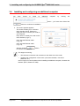
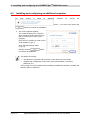
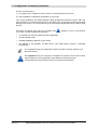
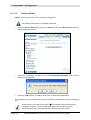
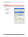
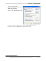
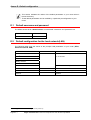
1) Configuring as a DHCP client
In Windows XP
•
click Start/Control Panel/Network
Connections.
•
right-click the appropriate network, and
then select Properties; the
Local Area Connection Properties
appears.
•
select the protocol TCP/IP of the
network card, and then click the
Properties button; the screen Internet
Protocol (TCP/IP) Properties
appears.
•
select the general tab, then the case
"Obtain an IP address automatically"
and the case "Obtain the addresses
of the DNS servers automatically".
•
click the OK button to confirm your
choice.
SAGEM F@st™ 240x/244x Reference Manual - 288097371-02
Sagem Communication document. Reproduction and disclosure prohibited
Page 5-3
5 - Configuration of network parameters
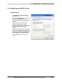
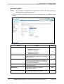
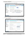
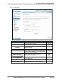
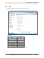
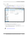
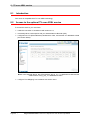
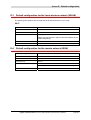
2) Data of the DHCP server
To obtain this data:
•
Open your browser and then enter http://myrouter or http://192.168.1.1 (default
IP address of the router) to access the welcome screen,
•
Click the "LAN" menu of the heading Advanced Setup; the following screen appears:
SAGEM F@st™ 240x/244x Reference Manual - 288097371-02
Page 5-4
Sagem Communication document. Reproduction and disclosure prohibited
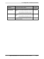
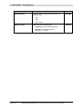
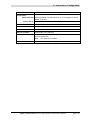
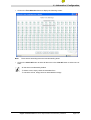
5 - Configuration of network parameters
Field
Meaning
IP Address
Displays the sub-network address
Subnet Mask
Displays the sub-network mask of the IP network.
Start IP Address
Displays the first address attributed by the DHCP
server.
Note :
End IP Address
Leased Time (hour)
192.168.1.1
255.255.255.0
192.168.1.2
This IP address must belong to the same
sub-network as that of the local network.
Displays the last address attributed by the DHCP
server.
Note :
Display
192.168.1.254
This IP address must belong to the same
sub-network as that of the local network.
Displays the period for obtaining (in hours) an IP
address for a terminal.
24
SAGEM F@st™ 240x/244x Reference Manual - 288097371-02
Sagem Communication document. Reproduction and disclosure prohibited
Page 5-5
5 - Configuration of network parameters
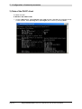
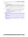
3) Data of the DHCP client
To obtain this data:
In Windows XP, 2000 and Me
¾
Click the Start button, select Execute, enter cmd and then click OK; the command prompt
screen appears. Enter ipconfig /all (or ipconfig/all) then confirm by pressing Enter.
SAGEM F@st™ 240x/244x Reference Manual - 288097371-02
Page 5-6
Sagem Communication document. Reproduction and disclosure prohibited
6. Information / Configuration
This section covers
¾
Accessing the welcome screen
§ 6.1
¾
Recommendations for using the configuration screens
§ 6.2
¾
The ADSL connection status
§.6.3
¾
Indications displayed on the display frame located in the
HTTP configurer window
§ 6.4
¾
The "Status" section
§ 6.5
¾
The "Internet Connection" section
§ 6.6
¾
The "Wireless" section
§ 6.7
¾
The "NAT" section
§ 6.8
¾
The "Advanced Setup" section
§ 6.9
¾
The "Advanced Status" section
§ 6.10
¾
The "Management" section
§ 6.11
SAGEM F@st™ 240x/244x Reference Manual - 288097371-02
Sagem Communication document. Reproduction and disclosure prohibited
Page 6-1
6 - Information / Configuration
6.1
Accessing the welcome screen
To access this screen, you must have configured the one of your computer's
interfaces using the installation CD-ROM provided with your router:
•
•
SAGEM F@stTM 2400/2440
TM
SAGEM F@st
2404/2444
see chapter 3.
see chapter 4.
If you are using your computer's Ethernet card to configure your router, connect it to the
Ethernet port whose socket is marked ETH (yellow box).
Your router is then configured using a simple Web browser (e.g. Internet Explorer).
The router's DHCP server function is activated by default with an address range
defined as indicated in §.6.9.2.
This chapter details the Machine Man Interface (MMI) of a router SAGEM F@stTM
2404/2444 which has four Ethernet interfaces.
In the case of a router SAGEM F@stTM 2400/2440 which has an additional
interface USB, this difference will be mentioned in the circumstance.
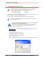
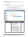
To access the configurer, proceed as follows:
1
In the Start menu, select All Programs / SAGEM F@st 2404, then left click on
.
2
The following screen asks you to connect.
Enter admin by default in the "Username" field.
Enter admin by default in the "Password" field.
Then click on OK to confirm.
Note:
The equipment's IP address (192.168.1.1) appears in the bar at the top of the
screen.
SAGEM F@st™ 240x/244x Reference Manual - 288097371-02
Page 6-2
Sagem Communication document. Reproduction and disclosure prohibited
6 - Information / Configuration
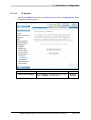
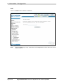
3
Your computer's Web browser opens and displays the router's welcome screen.
The equipment's name is displayed in title (SAGEM F@stTM 2400 or
SAGEM F@stTM 2404).
Equipment configuration sections appear in the left hand area in the welcome
screen.
This screen displays:
) in the centre, an area which shows the current ADSL connection status (cf. § 6.3).
) in the top right, a display box which lets you know the status of the ADSL line, lets you
refresh the window displayed and restart your router at any time (cf. § 6.4).
) to the left, a list of 7 sections (cf. § 6.5 to 6.11) made up of menus and sub-menus. These
let you view and configure your router's parameters.
You can modify the password to access your router's configurer to optimise the
safety of your network.
SAGEM F@st™ 240x/244x Reference Manual - 288097371-02
Sagem Communication document. Reproduction and disclosure prohibited
Page 6-3
6 - Information / Configuration
6.2
Recommendations
The meaning of the main buttons most commonly present in all the configuration windows is
provided in the table below.
Click on this button to add a new window to fill in the fields used to add
an object.
Click on this button to return to the previous screen.
Click on this button to close the active window and return to the main
screen.
Click on this button to display a new window to modify the fields that can
be accessed for a previously selected object.
Click on this button to display the next screen.
Click on this button to remove a selected object from a list.
Note:
You must check the "Remove" box to delete this object.
Click on this button to save the entry in the router's non-volatile (flash)
memory.
Note:
This value will only be taken into account when you restart your
router.
Click on this button to save the entry in the router's non-volatile (flash)
memory.
Note:
This value will be taken into account immediately without you
having to restart your router.
Click on this button to save the entry in the router's non-volatile (flash)
memory then restart your computer.
Basic principles
1) To make this guide easier to read and understand, it does not state that each time you enter
information into a screen you must click on Save or Save/Apply or Save/Reboot (except,
of course, if this is necessary).
2) When you select a section, the screen for the first menu in the section is displayed. In the
same way, when you select a menu, the screen for the first sub-menu is displayed.
3) All the fields in the different screens are explained in a table.
SAGEM F@st™ 240x/244x Reference Manual - 288097371-02
Page 6-4
Sagem Communication document. Reproduction and disclosure prohibited
6 - Information / Configuration
6.3
ADSL connection status
Refer to § 6.5.1 - Status/Summary.
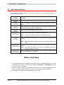
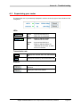
6.4
Display frame
This supervision box is displayed permanently at the top right of each HTTP configurer window.
The different objects it contains are explained below.
LEDs
Green
Synchronised ADSL line
Yellow
ADSL line synchronising
Red
ADSL line not connected
Green
Connected
Public address (WAN) distributed to the
router.
Yellow
Waiting for ISP
ADSL line synchronising or public address
(WAN) not distributed to the router
ADSL Down
Public address (WAN) not distributed to the
router, or ADSL line not synchronised.
Off
Not configured
No VC (Virtual Channel) configured
Router Rebooting Router restarted
Red
Access denied
Wrong Login and/or Password
Transmission rates
Displays the nominal down line transmission rate
Displays the nominal up line transmission rate
Buttons
Allows data displayed on the screen to be refreshed
Allows your router to be started
SAGEM F@st™ 240x/244x Reference Manual - 288097371-02
Sagem Communication document. Reproduction and disclosure prohibited
Page 6-5
6 - Information / Configuration
6.5
Status
Clicking on this heading displays the following menus:
•
Summary (cf. 6.5.1),
•
Diagnostics (cf. 6.5.2).
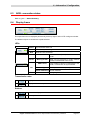
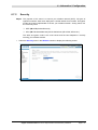
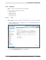
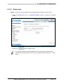
6.5.1
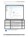
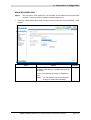
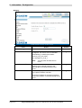
Summary
Object: This menu lets you display the current status of your Internet connection.
•
Select the Summary menu in the Status section; the following screen opens:
This screen also appears in the welcome screen (see § 6.1).
The following table provides the meaning of the different fields which are displayed.
Field
Meaning
Software Version
Software version currently installed.
Line Rate - Upstream (kbps)
Nominal up line rate
Line Rate - Downstream (kbps) Nominal down line rate
LAN IP Address
Local network IP address (LAN)
WAN IP Address
Remote network IP address (WAN)
Default Gateway
Default gateway address
Primary DNS Server
Primary DNS server address
Secondary DNS Server
Secondary DNS server address
Date / Time
Date and Time (see Note)
SAGEM F@st™ 240x/244x Reference Manual - 288097371-02
Page 6-6
Sagem Communication document. Reproduction and disclosure prohibited
6 - Information / Configuration
Note:
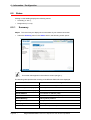
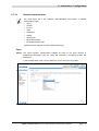
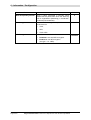
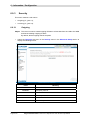
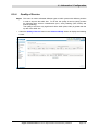
6.5.2
This field only appears if in the "Management / Internet Time" menu (see § 6.11.4),
the "Automatically synchronize with Internet time servers" box is checked.
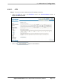
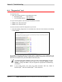
Diagnostics
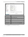
Object: This menu is used to display all the tests performed on the connections made from
your router to your Internet Service Provider (ISP). These tests concern:
•
the connection to your local network (LAN),
•
the connection to your "DSL Service Provider",
•
Connection to your "Internet Service Provider".
A hypertext link (help) enables the user to access context-related help. This help
gives an explanation concerning the state of the connection (PASS in green, DOWN
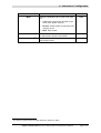
in orange and FAIL in red) and supplies the appropriate troubleshooting procedures.
The ADSL line translates the three statuses detailed in the table below.
State
Colour
PASS
Green
DOWN
Orange
Meaning
Indicates that the test was completed successfully.
Indicates that an interface (ETH, USB or Wi-Fi) has not been
detected.
Note: The USB interface exclusively concerns SAGEM F@stTM
2400/2440 router.
FAIL
Red
Indicates that the test has failed, or that it is impossible to start a
command.
If a test displays a "FAIL" state, click on "Help" and then the button
"Rerun Diagnostic Tests" at the bottom of the "Help" page, to check that the test
has been conclusive. If the test still displays "FAIL", you must follow the
troubleshooting procedure displayed on this page.
SAGEM F@st™ 240x/244x Reference Manual - 288097371-02
Sagem Communication document. Reproduction and disclosure prohibited
Page 6-7
6 - Information / Configuration
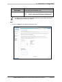
•
Select the Diagnostics menu in the Status section; the following screen opens:
SAGEM F@st™ 240x/244x Reference Manual - 288097371-02
Page 6-8
Sagem Communication document. Reproduction and disclosure prohibited
6 - Information / Configuration
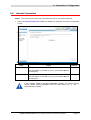
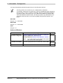
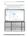
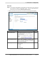
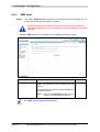
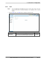
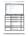
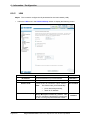
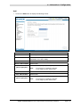
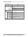
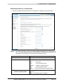
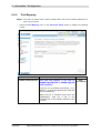
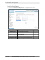
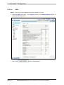
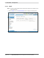
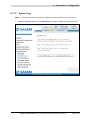
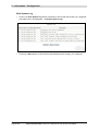
6.6
Internet Connection
Object: This menu lets you enter your connection ID and your connection password.
•
Select the Internet Connection heading to display the following connection configuration
screen:
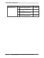
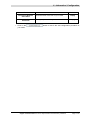
Field
Action
PPP Username
Enter your connection ID.
Default:
Empty
This information is provided to you by your Internet Service
Provider (ISP).
PPP Password
Enter your connection password.
Empty
This information is provided to you by your Internet Service
Provider (ISP).
If the message "There is no ppp connection" appears, this means that the
remote network (WAN) parameters have not been filled in (cf. § - 6.9.1 Advanced Setup / WAN).
SAGEM F@st™ 240x/244x Reference Manual - 288097371-02
Sagem Communication document. Reproduction and disclosure prohibited
Page 6-9
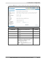
6 - Information / Configuration
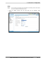
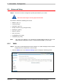
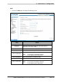
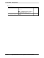
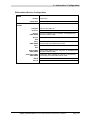
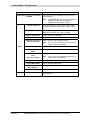
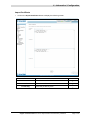
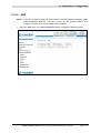
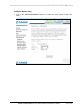
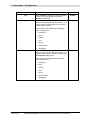
6.7
Wireless
Object: This menu lets you configure all the basic and advanced parameters of a wireless
network, and to activate this network.
This section contains the following five menus:
•
Basic (cf. § 6.7.1),
•
Security (cf. § 6.7.2),
•
MAC Filter (cf. § 6.7.3),
•
Advanced (cf. § 6.7.4),
•
Quality of Service (cf. § 6.7.5).
The Security, MAC Filter, Advanced and Quality of Service menus are used
to configure the advanced parameters in the Wireless section. These menus are
only displayed if, in the Basic menu the "Enable Advanced Wireless
Configuration" box is checked (not checked by default).
These menus must only be used by experienced users.
6.7.1
•
Basic
Select the Basic menu in the Wireless section to display the following wireless network
configuration screen:
SAGEM F@st™ 240x/244x Reference Manual - 288097371-02
Page 6-10
Sagem Communication document. Reproduction and disclosure prohibited
6 - Information / Configuration
6.7.1.1
Wireless - Basic
Field
Enable Wireless
Action/Meaning
Default:
Check the appropriate box to activate the wireless
network (Wi-Fi).
Box
checked
Note:
Hide Access Point
The "Wi-Fi" LED which lights up steady on the
front of the router shows that the wireless
network (Wi-Fi) is activated.
Check the appropriate box to mask the broadcast of the
SSID and prevent any Wi-Fi connection on your router.
Note:
When this box is checked, the router's SSID is
absent from the Wi-Fi adaptor user's own list of
monitored sites (Access Point).
Enter your router's SSID.
SSID
Note:
Box not
checked
Sagem
This indicated on the label stuck to the box.
Country
Select the country of your choice from the scroll down
list.
FRANCE
BSSID
This is the MAC address of the router's Wi-Fi interface
(Access Point). In the "Structure" mode, this address
identifies a cell (BSS in English Basic Service Set).
This cell is a set formed by the access point and the
stations located in its coverage area.
_
Non modifiable
Channel
This is the radio channel used by the router and
its Wi-Fi clients to communicate with each other. This
channel must be the same for the router and all its
Wi-Fi clients.
Auto
Select the channel you want from the scroll down list
(auto, channels 1 to 13).
Note:
Channel 11 corresponds to frequency
2462 MHz.
Note:
If you select "Auto", the Wi-Fi equipment will
select the access point channel (router) which
will emit the strongest signal.
You will find an identical "Channel" field in the
"Advanced" menu of this same section. Any
modifications are carried over from one field to
another.
Conform to the CE Declaration of conformity / Radio
rules list in appendix B to paragraph B.2.
SAGEM F@st™ 240x/244x Reference Manual - 288097371-02
Sagem Communication document. Reproduction and disclosure prohibited
Page 6-11
6 - Information / Configuration
6.7.1.2
Quick Wireless - Security - Configuration
Field
Network
Authentication
Note:
Action/Meaning
Default:
From the scroll down list, select the security adapted
to your router's wireless network. The list suggests the
following choices:
NO
•
NO : There is no protection for the wireless
network,
•
WEP : Activation of WEP (Wired
Equivalent Privacy) encryption
•
WPA-PSK : Activation of the WPA
(Wireless Protected Access)
•
WPA2-PSK : Activation of the WPA2
(Wireless Protected Access)
•
Other (see § 6.7.2.1).
The router may or may not be secured, at the request of the customer. This level of
security is indicated on the label pasted to the box.
This choice will modify the Wireless configuration screen.
SAGEM F@st™ 240x/244x Reference Manual - 288097371-02
Page 6-12
Sagem Communication document. Reproduction and disclosure prohibited
6 - Information / Configuration
WEP
•
Select the "WEP" encryption mode from the scroll down list; the following screen appears:
Field
Action/Meaning
Default:
Encryption Strength
Select 64-bit or 128-bit for an encryption at 64 bits or
128 bits respectively.
128-bit
Key phrase
Enter a phrase that consists of up to 15 alphanumeric
characters then click the Generate Keys button.
Empty
Current network key
Select a key from the four suggested. The emission
key is used to encrypt the data sent by your
computer.
Network key x (1 to 4)
The WEP key is customised for your router.
1
Empty
You may modify the keys by entering them directly
into the boxes.
The characters are "0" to "9" and "A" to "F".
Store the key phrase and the keys in a safe location.
Do not write them in a file on your computer.
SAGEM F@st™ 240x/244x Reference Manual - 288097371-02
Sagem Communication document. Reproduction and disclosure prohibited
Page 6-13
6 - Information / Configuration
You may automatically generate encryption keys or manually enter the keys.
The "Key phrase" can consist of up to 15 alphanumeric characters.
To manually configure the encryption key, enter five hexadecimal pairs of digits for
each 64-bit key, or enter 13 pairs for the single 128-bit key (A hexadecimal digit is
a number or letter in the range 0-9 or A-F). Note that the WEP key protects data
transmitted between wireless nodes, but does not protect any transmissions over
your wired network (LAN) or over Internet (WAN) using Internet Explorer 5.0 or
above.
WPA-PSK
See § 6.7.2.1 - WPA-PSK
WPA2-PSK
See § 6.7.2.1 - WPA2-PSK
Other
See § 6.7.2.1.
Advanced Wireless
Field
Meaning
Enable advanced
Check the appropriate box to be able to display the
Wireless Configuration Security, MAC Filter, Advanced and
Quality of Service menus in the "Wireless" section.
Note:
Enable Guest SSID
Guest SSID
Default
Box not
checked
If you check this box, the "Enable Guest SSID"
and "Guest SSID" fields appear.
Check the appropriate box to activate the "Guest SSID".
Enter a name for the "Guest SSID".
SAGEM F@st™ 240x/244x Reference Manual - 288097371-02
Page 6-14
Sagem Communication document. Reproduction and disclosure prohibited
Box not
checked
Guest
6 - Information / Configuration
6.7.2
Security
Object: The purpose of this menu is to secure your wireless network (Wi-Fi). All types of
ingenious solutions have been deployed to combat attacks from hackers. Encryption
modes have been implemented to secure your wireless network. Among these, two
are commonly used:
¾
WEP (Wired Equivalent Protocol),
¾
WPA (Wi-Fi Protected Access) and its derivatives (WPA-PSK, WPA2 etc.).
The WPA encryption mode is the most robust and the best adapted to correctly
securing your wireless network.
•
Select the Security menu in the Wireless section to display the following screen:
SAGEM F@st™ 240x/244x Reference Manual - 288097371-02
Sagem Communication document. Reproduction and disclosure prohibited
Page 6-15
6 - Information / Configuration
Field
Meaning
Select SSID
Select the "SSID" of your choice from the scroll
down list (sagem or Guest).
Network Authentication
From the scroll down list, select the security
adapted to your router's wireless network. The list
suggests the following choices:
•
Open : There is no protection for the wireless
network (Open System).
•
Shared :
•
802.1x : Activation of the 802.1x standard,
•
WPA : Activation of WPA (Wireless Protected
Access),
•
WPA-PSK : Activation of WPA-PSK,
•
WPA2 : Activation of WPA2,
•
WPA2-PSK : Activation of WPA2-PSK,
•
Mixed WPA2/WPA : Activation of
Mixed WPA2/WPA,
•
Mixed WPA2/WPA-PSK : Activation of
Mixed WPA2/WPA-PSK,
Default
sagem
Open
This choice will modify the Wireless configuration
screen.
WEP Encryption
Select from the scroll down list:
•
Disabled to not use WEP encryption.
•
Enabled to use WE encryption
(see § 6.7.1.2 - WEP).
SAGEM F@st™ 240x/244x Reference Manual - 288097371-02
Page 6-16
Sagem Communication document. Reproduction and disclosure prohibited
Disabled
6 - Information / Configuration
6.7.2.1
Network Authentication
The scroll down list in the "Network Authentification" field shows 9 possible
authentication types:
•
Open,
•
Shared,
•
80.2.1x,
•
WPA,
•
WPA-PSK,
•
WPA2,
•
WPA2-PSK,
•
Mixed WPA2/WPA,
•
Mixed WPA2/WPA-PSK.
A different screen appears for each authentication type.
Open
Object: The "Open System" authentication enables all users of the Wi-Fi network to
authenticate themselves with the router. No restrictions concerning security are
demanded.
In this authentication mode, only the WEP key may be used to encrypt data.
SAGEM F@st™ 240x/244x Reference Manual - 288097371-02
Sagem Communication document. Reproduction and disclosure prohibited
Page 6-17
6 - Information / Configuration
Shared
Object: This level of security enables users of the Wi-Fi network to be authenticated using
their SSID or their WEP key.
In this authentication mode, the WEP key is used to encrypt data.
•
Select the "Shared" security from the scroll down list; the following screen appears:
Field
WEP Encryption
Action
Note:
Default
This field is always active (Enabled).
Enabled
(non modifiable)
Encryption Strength
See § 6.7.1.2 - WEP.
128-bit
Key Phrase
See § 6.7.1.2 - WEP.
Empty
Current Network Key
See § 6.7.1.2 - WEP.
2
Network Key x (1 to 4)
See § 6.7.1.2 - WEP.
Empty
SAGEM F@st™ 240x/244x Reference Manual - 288097371-02
Page 6-18
Sagem Communication document. Reproduction and disclosure prohibited
6 - Information / Configuration
802.1x
Object:
The "802.1x" standard is based on the EAP protocol (Extensible Authentication
Protocol). This enables users of the Wi-Fi network to be authenticated using a
"RADIUS" authentication server (Remote Authentication Dial-in User Service).
In this case, the WEP key is used exclusively for data encryption.
•
Select the security according to the "802.1x" protocol from the scroll down list; the following
screen appears:
Field
Action
Default
RADIUS Server IP Address
Enter the IP address of the "RADIUS"
authentication server.
0.0.0.0
RADIUS Port
Enter the port used for the "RADIUS"
authentication server.
1812
RADIUS Key
Enter the secret key shared between the
authentication server and its clients
WEP Encryption
Note:
Encryption Strength
See § 6.7.1.2 - WEP.
128-bit
Key Phrase
See § 6.7.1.2 - WEP.
Empty
Current Network Key
Select key 2 or 3
(see § 6.7.1.2 - WEP).
2
This field is always active (Enabled).
_
Enabled
SAGEM F@st™ 240x/244x Reference Manual - 288097371-02
Sagem Communication document. Reproduction and disclosure prohibited
Page 6-19
6 - Information / Configuration
Field
Network Key x (1 to 4)
Action
1
This field is empty or displays the key
value entered earlier (greyed out)
2
Enter the encryption on the key you
selected in the "Current Key" (see
§ 6.7.1.2- WEP).
3
Enter the encryption on the key you
selected in the "Current Key" (see
§ 6.7.1.2- WEP).
4
This field is empty or displays the key
value entered earlier (greyed out)
Default
Non modifiable
Non modifiable
SAGEM F@st™ 240x/244x Reference Manual - 288097371-02
Page 6-20
Sagem Communication document. Reproduction and disclosure prohibited
6 - Information / Configuration
WPA
Object: This encryption mode applies the functionalities of the WPA protocol and requires the
use of a "RADIUS" authentication server.
•
Select the "WPA" security from the scroll down list; the following screen appears:
Field
Action
Default
WPA Group Rekey Interval
Enter a value, expressed in seconds, which
determines the period after which the WPA
key will be regenerated (Renewing) in
broadcast / multicast (LAN broadcast).
RADIUS Server IP Address
Enter the IP address of the "RADIUS"
authentication server.
0.0.0.0
RADIUS Port
Enter the port used by the "RADIUS"
authentication server.
1812
RADIUS Key
Enter the secret key shared between the
authentication server and its clients
WPA encryption
Select the WPA encryption required from the
scroll down list:
•
TKIP (Temporal Key Integration
Protocol),
•
AES (Advanced Encryption Standard),
•
TKIP+ AES.
0
_
TKIP
SAGEM F@st™ 240x/244x Reference Manual - 288097371-02
Sagem Communication document. Reproduction and disclosure prohibited
Page 6-21
6 - Information / Configuration
Field
WEP encryption
Action
Select from the scroll down list:
•
Disabled to use WPA encryption only.
•
Enabled to use both WPA and WEP
encryption
(see § 6.7.1.2 - WEP).
SAGEM F@st™ 240x/244x Reference Manual - 288097371-02
Page 6-22
Sagem Communication document. Reproduction and disclosure prohibited
Default
Disabled
6 - Information / Configuration
WPA-PSK
Object: This encryption mode applies the functionalities of the WPA protocol with a pre-shared
key, but does not require an authentication server. The key is regenerated after a
period which can be configured (WPA Group Rekey Interval).
•
Select the "WPA-PSK" security from the scroll down list; the following screen appears:
Field
WPA Pre-Shared Key
Action
Default
Enter the secret shared key. This may contain 8
to 63 ASCII characters or 64 hexadecimal
symbols (256 bits).
Empty
Click on the "Save/Apply" button to validate the
entry.
Note:
You may display your secret phrase by
clicking on "Click here to display".
WPA Group Rekey Interval
Enter a value, expressed in seconds, which
determines the period after which the WPA key
will be regenerated (Renewing) in broadcast /
multicast (LAN broadcast).
WPA encryption
Select the WPA encryption required from the
scroll down list:
•
TKIP,
•
AES,
•
TKIP+ AES.
0
TKIP
SAGEM F@st™ 240x/244x Reference Manual - 288097371-02
Sagem Communication document. Reproduction and disclosure prohibited
Page 6-23
6 - Information / Configuration
Field
WEP encryption
Action
Select from the scroll down list:
•
Disabled to use WPA encryption only.
•
Enabled to use both WPA and WEP
encryption
(see § 6.7.1.2 - WEP).
Default
Disabled
SAGEM F@st™ 240x/244x Reference Manual - 288097371-02
Page 6-24
Sagem Communication document. Reproduction and disclosure prohibited
6 - Information / Configuration
WPA2
Object:
•
This encryption mode applies the functionalities of the WPA2 protocol and requires
the use of a "RADIUS" authentication server.
Select the
appears:
"WPA2"
security
from
the
scroll
down
list;
the
following
screen
SAGEM F@st™ 240x/244x Reference Manual - 288097371-02
Sagem Communication document. Reproduction and disclosure prohibited
Page 6-25
6 - Information / Configuration
Field
WPA2 Preauthentication-
Action
Select from the scroll down list:
•
Disabled to deactivate the
WPA2 pre-authentication,
•
Enabled to activate the
WPA2 pre-authentication,
Default
Disabled
Network Re-auth Interval
Enter a value, expressed in seconds, which
determines the period after which the WPA
key will be certified.
36000
WPA Group Rekey Interval
Enter a value, expressed in seconds, which
determines the period after which the WPA
key will be regenerated (Renewing) in
broadcast / multicast (LAN broadcast).
0
RADIUS Server IP Address
Enter the IP address of the "RADIUS"
authentication server.
0.0.0.0
RADIUS Port
Enter the port used by the "RADIUS"
authentication server.
1812
RADIUS Key
Enter the secret key shared between the
authentication server and its clients.
WPA encryption
Select the WPA encryption required from the
scroll down list:
WEP encryption
•
TKIP,
•
AES,
•
TKIP+ AES.
Select from the scroll down list:
•
Disabled to use WPA encryption only.
•
Enabled to use both WPA and WEP
encryption
(see § 6.7.1.2 - WEP).
_
AES
Disabled
SAGEM F@st™ 240x/244x Reference Manual - 288097371-02
Page 6-26
Sagem Communication document. Reproduction and disclosure prohibited
6 - Information / Configuration
WPA2-PSK
Object: This encryption mode uses the WPA2 protocol with a pre-shared key, but does not
require an authentication server. The key is regenerated after a period which can be
configured (WPA Group Rekey Interval).
•
Select the "WPA2-PSK" security from the scroll down list; the following screen
appears:
Field
WPA Pre-Shared Key
Action
Default
Enter a secret phrase. This may contain 8 to 63
ASCII characters or 64 hexadecimal symbols
(256 bits).
Empty
Click on the "Save/Apply" button to validate the
entry.
Note:
You may display your secret phrase by
clicking on "Click here to display".
WPA Group Rekay Interval
Enter a value, expressed in seconds, which
determines the period after which the WPA key
will be regenerated (Renewing) in broadcast /
multicast (LAN broadcast).
WPA encryption
Select the WPA encryption required from the
scroll down list:
•
TKIP,
•
AES,
•
TKIP+ AES.
0
AES
SAGEM F@st™ 240x/244x Reference Manual - 288097371-02
Sagem Communication document. Reproduction and disclosure prohibited
Page 6-27
6 - Information / Configuration
Field
WEP encryption
Action
Select from the scroll down list:
•
Disabled to use WPA encryption only.
•
Enabled to use both WPA and WEP
encryption
(see § 6.7.1.2 - WEP).
Default
Disabled
SAGEM F@st™ 240x/244x Reference Manual - 288097371-02
Page 6-28
Sagem Communication document. Reproduction and disclosure prohibited
6 - Information / Configuration
Mixed WPA2/WPA
Object:
•
This encryption mode applies the functionalities of the WPA2 and WPA protocols. It
needs a "RADIUS" authentication server.
Select the "Mixed WPA2/WPA" security from the scroll down list; the following screen
appears:
Field
WPA2 Preauthentication-
Action
Select from the scroll down list:
•
Disabled to deactivate the
WPA2 pre-certification,
•
Enabled to activate the
WPA2 pre-certification,
Default
Disabled
Network Re-auth Interval
Enter a value, expressed in seconds, which
determines the period after which the WPA key
will be certified.
36000
WPA Group Rekey Interval
Enter a value, expressed in seconds, which
determines the period after which the WPA key
will be regenerated (Renewing) in broadcast /
multicast (LAN broadcast).
0
RADIUS Server IP Address
Enter the IP address of the "RADIUS"
authentication server.
0.0.0.0
RADIUS Port
Enter the port used by the "RADIUS"
authentication server.
1812
RADIUS Key
Enter the secret key shared between the
authentication server and its clients
_
SAGEM F@st™ 240x/244x Reference Manual - 288097371-02
Sagem Communication document. Reproduction and disclosure prohibited
Page 6-29
6 - Information / Configuration
Field
WPA encryption
WEP Encryption
Action
Select the WPA encryption required from the
scroll down list:
•
TKIP,
•
AES,
•
TKIP+ AES.
Select from the scroll down list:
•
Disabled to not use WEP encryption.
•
Enabled to use WE encryption
(see § 6.7.1.2 - WEP).
SAGEM F@st™ 240x/244x Reference Manual - 288097371-02
Page 6-30
Sagem Communication document. Reproduction and disclosure prohibited
Default
TKIP+AES
Disabled
6 - Information / Configuration
Mixed WPA2/WPA-PSK
Object:
•
This encryption mode applies the functionalities of the WPA2-PSK and WPA-PSK
protocols. It does not need a "RADIUS" authentication server.
Select the "Mixed WPA2 /WPA-PSK" security from the scroll down list; the following screen
appears:
Field
WPA Pre-Shared Key
Action
Enter a secret phrase. This may contain 8 to
63 ASCII characters or 64 hexadecimal symbols
(256 bits).
Default
Empty
Click on the "Save/Apply" button to validate the
entry.
Note:
You may display your secret phrase by
clicking on "Click here to display".
SAGEM F@st™ 240x/244x Reference Manual - 288097371-02
Sagem Communication document. Reproduction and disclosure prohibited
Page 6-31
6 - Information / Configuration
Field
Action
Default
WPA Group Rekey Interval
Enter a value, expressed in seconds, which
determines the period after which the WPA key
will be regenerated (Renewing) in broadcast /
multicast (LAN broadcast).
0
WPA encryption
Select the WPA encryption required from the
scroll down list:
WEP Encryption
•
TKIP,
•
AES,
•
TKIP+ AES.
Select from the scroll down list:
•
Disabled to not use WEP encryption.
•
Enabled to use WE encryption
(see § 6.7.1.2 - WEP).
SAGEM F@st™ 240x/244x Reference Manual - 288097371-02
Page 6-32
Sagem Communication document. Reproduction and disclosure prohibited
TKIP+ AES
Disabled
6 - Information / Configuration
6.7.3
MAC Filter
Object: The "MAC Filter" function is used to limit the number of computers which can access
your wireless network.
•
Select the MAC Filter menu in the Wireless section to display the following screen:
Field
MAC Restrict Mode
Meaning
Select the command by checking the appropriate box:
Disabled
: Deactivates the MAC filtering,
Allow
: Enables computers whose MAC address
is in the list to use your wireless network,
Denied
: Refuses computers whose MAC address
is in the list to use your wireless network.
Default
Disabled
SAGEM F@st™ 240x/244x Reference Manual - 288097371-02
Sagem Communication document. Reproduction and disclosure prohibited
Page 6-33
6 - Information / Configuration
Add
•
Click on the Add button to add a MAC address to be filtered (address of a computer
authorised to connect to a wireless network).
SAGEM F@st™ 240x/244x Reference Manual - 288097371-02
Page 6-34
Sagem Communication document. Reproduction and disclosure prohibited
6 - Information / Configuration
6.7.4
Advanced
Object: This menu is used to configure the essential parameters of your wireless network
(WLAN) 802.11 and configure certain security parameters.
•
Select the Advanced menu in the Wireless section to display the following screen:
SAGEM F@st™ 240x/244x Reference Manual - 288097371-02
Sagem Communication document. Reproduction and disclosure prohibited
Page 6-35
6 - Information / Configuration
The table below indicates in more detail how to access your Wi-Fi port
(or Access Point).
Nevertheless, it is best to leave the default values for easier usage.
Field
AP Isolation
Meaning
Select from the scroll down list:
Off
: to not isolate the Access Point i.e.
authorise machines connected to the
router to communicate with each other.
On
: to isolate the Access point, i.e. prohibit
machines connected to the router to
communicate with each other.
Band
Select the 2.4 GHz band for the IEEE 802.11g
standard.
Channel
See Wireless/Basic § 6.7.1.1.
Rate
In the scroll down list, select the transmission rate
at which the information (data or video) will be
transmitted or received on your wireless network
(Auto, 1, 2, 5.5, 6, 9, 11, 12, 18, 24, 36, 48 or
54 Mbps).
Note:
Multicast Rate
Off
2.4GHz802.11g
11
Auto
If you select "Auto", the information will
be transmitted at an optimised rate
which takes account of the transmission
constraints.
From scroll down list, select the transmission rate
at which the "Multicast" packets are transmitted
(Auto, 1, 2, 5.5, 6, 9, 11, 12, 18, 24, 36, 48 or
54 Mbps).
Note:
Default
Auto
If you select "Auto", the information will
be transmitted at an optimised rate
which takes account of the transmission
constraints.
Video conferencing and teleconferencing are
"Multicast" applications.
Basic Rate
From the scroll down list, select the basic rate at
which the information will be transmitted or
received over your wireless network (Default, All,
1 & 2 Mbps or 1 & 2 & 5.5 & 6 & 11 & 12 &
24 Mbps).
Default
Fragmentation Threshold
This packet fragmentation mechanism is used to
limit errors and repetitions.
2346
It is recommended not to reduce the packet size
too much to avoid reducing the bandwidth.
Enter a threshold value, expressed in bytes,
between 256 and 2347.
SAGEM F@st™ 240x/244x Reference Manual - 288097371-02
Page 6-36
Sagem Communication document. Reproduction and disclosure prohibited
6 - Information / Configuration
Field
RTS Threshold
Meaning
Default
The RTS/CTS protocol (Request To Send / Clear
To Send) is used to reduce the probability of
collisions between stations.
2347
Note: As packet size is set by default to 2346,
the RTS/CTS protocol is inhibited as its
value is set by default to 2347.
Enter a threshold value, expressed in bytes,
between 1 and 2347.
DTIM Interval
The DTIM counting area (Delivery Traffic Indication
Message) enables Wi-Fi clients to listen to
broadcast and multicast messages saved in your
router's "Buffer" memory.
1
Enter an interval value, expressed in seconds,
between 1 and 255.
Beacon Interval
Enter a time interval value between two beacon
signals which shows the activity of the wireless
network.
100
This interval value, expressed in ms (milliseconds)
is between 1 and 1000.
XPressTM Technology
From the scroll down list, select Enabled to apply
the "XPressTM" technology or Disabled to not
apply it.
Disabled
54gTM Mode
In the scroll down list, select (54g Auto, 54g
Performance, 54g LRS or 802.11b Only)
54g Auto
54g Protection
Select Auto to improve the quality in the mixed
802.11 environments (g and b for example) or Off
to improve the quality only on the 802.11g
environments but degrade it on other
environments (802.11b for example).
Regulatory Mode
In the scroll down list, select the particular
IEEE802.11 standard to which you want your
network to conform (Disabled, 802.11h or
802.11d).
802.11h
Conformity with European
regulations in terms of frequency and
energy saving.
802.11d
Internationalisation.
Auto
Disabled
SAGEM F@st™ 240x/244x Reference Manual - 288097371-02
Sagem Communication document. Reproduction and disclosure prohibited
Page 6-37
6 - Information / Configuration
Field
Meaning
1
Pre-Network Radar Check
In-Network Radar Check
TPC Mitigation (db)
1
Afterburner Technology
1
If 802.11 h is selected enter here the duration of
the radar detection sweep when the AP (Access
Point) starts up.
If 802.11 h is selected, enter here the duration of
the radar detection sweep during transmission.
If 802.11 h is selected, select in the scroll down
list an attenuation value (0(Off), 2, 3 or 4),
expressed in dB, of the TPC (Transmit Power
Control).
From the scroll down list, select Enabled to apply
the "Afterburner" technology or Disabled to not
apply it.
Default
60
60
0(Off)
Disabled
This technology tends to increase the
transmission return.
Note: This field may be greyed out (non
modifiable) if you select Enabled in the
"WMM (Wifi MultiMedia)" field in the
Wireless/Quality of Service menu.
Preamble Type
Note: This field only appears if you selected
"802.11b only" (only the wireless network
with a maximum theoretical transmission
rate of 11 Mbps) in the 54gTM Mode field.
long
In the IEEE 802.11 standard, the "preamble" is
used to synchronise the Emitter and Receiver
correctly. The "long preamble" is generally
commonly used. For reasons of bandwidth gain,
this standard proposes reducing the length of the
"preamble".
In the scroll down list, select long to keep a
128 bit "preamble" or short to reduce it to 56 bits.
Transmit Power
If 802.11 h is selected, in the scroll down list
select the cyclical emission ratio (20%, 40 %,
60 %, 80 % or 100 %) at which you want to
transmit.
Note: The power rate will be selected according
to your environment.
1
This field is active if the "802.11h" option was selected in the "Regulatory Mode" field.
SAGEM F@st™ 240x/244x Reference Manual - 288097371-02
Page 6-38
Sagem Communication document. Reproduction and disclosure prohibited
100%
6 - Information / Configuration
6.7.5
Quality of Service
Object:
•
The Wi-Fi quality of service for your router conforms to the WMM (Wifi MultiMedia)
specification. This standard improves the performances of Wi-Fi links by acting on
the data flows (packet size, bit rates, etc.) and the length of queues while respecting
bandwidth requirements (managed by the router).
Select the Quality of Service menu in the Wireless section to display the following screen:
Field
WMM (Wi-Fi Multimedia)
WMM No Acknowledgement
Meaning
In the scroll down list, select the activation
(Enabled) or deactivation (Disabled) of the
WMM support.
Note:
The scroll down list may only be
operational if the "WMM (Wi-Fi
Multimedia)" field is activated.
Default
Disabled
Greyed
out
In the scroll down list, select Enabled or
Disabled to permit or prohibit a more effective
bit rate of the data flow with, on the other hand,
a higher error rate.
SAGEM F@st™ 240x/244x Reference Manual - 288097371-02
Sagem Communication document. Reproduction and disclosure prohibited
Page 6-39
6 - Information / Configuration
The following screen appears as soon as you activate "WMM".
Add
•
Click on the Add QoS Entry button to add a Wi-Fi Quality of Service (wifi QoS) rule; the
following screen appears.
SAGEM F@st™ 240x/244x Reference Manual - 288097371-02
Page 6-40
Sagem Communication document. Reproduction and disclosure prohibited
6 - Information / Configuration
Field
Action
Default
Traffic Class Name
Enter a name for the traffic class you want to
create.
Empty
Wireless Transmit Priority In the scroll down list, select the priority you
0 - WMM
want to allocate to the traffic class you Best Effort
selected (see table below).
(default)
Select the appropriate protocol from the scroll
down list (TCP/UDP, TCP, UDP, ICMP).
Empty
Enter a Source IP address (LAN).
Empty
Source Subnet Mask
Enter a sub-net mask associated with the
"Source" IP address.
Empty
UDP/TCP Source Port
(port or port:port)
Enter a "Source" port or range of ports.
Empty
Destination IP Address
Enter a "Destination" IP address (WAN).
Empty
Enter a sub-net mask associated with the
"Destination" IP address.
Empty
UDP/TCP Destination Port Enter a "Destination" port or range of ports.
(port or port:port)
Note: For one port, for example, enter 80.
For a range of ports, enter 80:90.
Empty
Protocol
Source IP Address
Destination Subnet Mask
Note:
Transmission priority
For one port, for example, enter 80.
For a range of ports, enter 80:90.
Meaning
0 - WMM Best Effort (default)
This is the lowest priority. This provides no guarantee of
data transmission.
1 - WMM Background
These are intermediate priorities. These provide routing
without too much data flow loss.
2 - WMM Background
3 - WMM Best Effort
This priority provides no guarantee of data transmission.
4 - WMM Video priority
These are intermediate priorities. They provide a correct
routing for "Video".
5 - WMM Video priority
6 - WMM Voice priority
7 - WMM Voice priority
Click on the
These are higher priorities. They provide complete routing
for voice
button to save the parameters.
SAGEM F@st™ 240x/244x Reference Manual - 288097371-02
Sagem Communication document. Reproduction and disclosure prohibited
Page 6-41
6 - Information / Configuration
6.8
NAT
Object: NAT is a configurable IP address translation function which will be applied to the
interfaces of your router which you will have activated for this function.
Several translation function configurations, the NAT actions, can be configured and
may be activated as indicated in the 6.8.1 - Add paragraph.
This section contains the following four menus:
•
Port forwarding (cf. § 6.8.1),
•
Port Triggering (cf. § 6.8.2),
•
DMZ Host (cf. § 6.8.3),
•
ALG (cf. § 6.8.4).
6.8.1
Port forwarding
Object: This menu is used to route directly to the External Ports the incoming data from a
Service server (such as, for example, FTP Server, SNMP, TFTP etc.) of the remote
network (WAN) to computers on the local network (LAN) via the Internal Ports.
•
Select the Port forwarding menu in the NAT section to display the following screen:
SAGEM F@st™ 240x/244x Reference Manual - 288097371-02
Page 6-42
Sagem Communication document. Reproduction and disclosure prohibited
6 - Information / Configuration
Field
Meaning
Server Name
Select a Service Service available over Internet (such as, for example FTP Server,
SNMP, TFTP etc.).
Custom Server Name you want to allocate to a local server.
External Port Start
Internal start port (WAN side).
External Port End
Internal end port (WAN side).
Protocol
Transport protocol (TCP, UDP or TCP/UDP).
Internal Port Start
Internal start port (LAN side).
Internal Port End
This internal end port (LAN side) is associated with the external
end port (WAN) side.
Note:
Server IP Address
This cannot be modified.
Computer address delivered by your router's DHCP server.
SAGEM F@st™ 240x/244x Reference Manual - 288097371-02
Sagem Communication document. Reproduction and disclosure prohibited
Page 6-43
6 - Information / Configuration
Add
•
Click on the Add button; the following screen appears:
SAGEM F@st™ 240x/244x Reference Manual - 288097371-02
Page 6-44
Sagem Communication document. Reproduction and disclosure prohibited
6 - Information / Configuration
Proceed as follows:
¾
Check the "Select a Service" box, then select the service of your choice from the scroll
down list, for example "SNMP".
The "External Port Start", "External Port End", "Internal Port Start", "Internal Port End"
and Protocol fields (transport protocol associated with this service) are automatically filled
in the table.
Note:
You may complete the table by adding other ports associated with a protocol.
or
¾
Check the "Custom Server" box, enter the name of the server you want to connect to, then:
•
Complete the ID Host of your computer's IP address (this is attributed by your router's
DHCP server).
•
Fill in the "External Port Start", "External Port End", "Internal Port Start",
"Internal Port End" and "Protocol" fields.
A few rules for entering values:
¾
When you want to select a single port, the start port ("External Port Start" or "Internal
Port Start") and the end port ("External Port End" or "Internal Port End") must be
identical.
¾
When you want to select a range of ports, the start port number must be lower than
the end port number.
¾
You must always start entering with the "External Port Start" and "External Port End"
ports,
¾
When you allocate a number to an "External Port Start", the same number is
automatically allocated to the "Internal Port Start" and identically for
"External Port End",
SAGEM F@st™ 240x/244x Reference Manual - 288097371-02
Sagem Communication document. Reproduction and disclosure prohibited
Page 6-45
6 - Information / Configuration
The following diagram contains an example:
The "Delta Force 2" service is available on your computer via the external ports 3568 and 3569
(WAN side) and via the internal ports 3568 and 3569 (LAN side).
SAGEM F@st™ 240x/244x Reference Manual - 288097371-02
Page 6-46
Sagem Communication document. Reproduction and disclosure prohibited
6 - Information / Configuration
6.8.2
Port Triggering
Object: The purpose of this menu is to open dynamically the firewall ports (open ports) via
"Trigger Ports" when an application (such as games or video) opens a connection via
the transport layer (TCP or UDP).
•
Select the Port Triggering menu in the NAT section to display the following screen:
Field
Meaning
Application
Name Application name
Trigger
Protocol Transport protocol (TCP, UDP or TCP/UDP).
Port Range A port range contains a Start port and an End port.
Note:
A single port is characterised by an identical start port
and end port.
Open
Protocol Transport protocol (TCP, UDP or TCP/UDP).
Port Range A port range contains a Start port and an End port.
Note:
A single port is characterised by an identical start port
and end port.
SAGEM F@st™ 240x/244x Reference Manual - 288097371-02
Sagem Communication document. Reproduction and disclosure prohibited
Page 6-47
6 - Information / Configuration
Add
•
Click on the Add button; the following screen appears:
To configure "Trigger Port" and "Open Port", proceed as follows:
¾
Check the "Select an application" box, then select the service of your choice from the
scroll down list, for example "Aim Talk".
The "Trigger Port Start", "Trigger Port End", "Trigger Port Start", "Trigger Port End"
and Protocol fields (transport protocol associated with this service) are automatically filled
in the table.
Note:
You may complete the table by adding other ports associated with a protocol.
or
¾
Check the "Custom Server" box then enter the name of the server you want to connect to,
then:
•
Complete the ID Host of your computer's IP address (this is attributed by your router's
DHCP server).
•
Fill in the "Trigger Port Start", "Trigger Port End", "Trigger Port Start",
"Trigger Port End" and "Protocol" fields.
SAGEM F@st™ 240x/244x Reference Manual - 288097371-02
Page 6-48
Sagem Communication document. Reproduction and disclosure prohibited
6 - Information / Configuration
A few rules for entering values:
¾
When you want to select a single port, the start port ("Trigger Port Start" or "Open
Port Start") and the end port ("Trigger Port End" or "Open Port End") must be
identical.
¾
When you want to select a range of ports, the start port number must be lower than
the end port number.
The following diagram contains an example:
Using the "Trigger" 3568 port (WAN side), the "Delta Force" service server triggers the opening
of port range 3100 to 3999 for your computer to access this service.
SAGEM F@st™ 240x/244x Reference Manual - 288097371-02
Sagem Communication document. Reproduction and disclosure prohibited
Page 6-49
6 - Information / Configuration
6.8.3
DMZ Host
Object:
This "DMZ" (DeMilitarized Zone) lets you access the server you selected directly via
the Internet without going through the "Firewall".
Caution, this process presents an intrusion risk. It is therefore vital that
you take precautions so that no connections may be initiated to the private
network.
•
Select the DMZ Host menu in the NAT section to display the following screen:
Field
Action
Default
DMZ Host IP Address
Enter the IP address of a server to activate the
"DMZ" and therefore access it directly from the
Internet.
Empty
To deactivate the "DMZ" zone, erase the address
entered in the field.
Note:
Click on the Save/Apply button to take
account of the address or its erasure.
The "DMZ" zone is deactivated by default.
SAGEM F@st™ 240x/244x Reference Manual - 288097371-02
Page 6-50
Sagem Communication document. Reproduction and disclosure prohibited
6 - Information / Configuration
6.8.4
ALG
Object:
•
The ALG (Application Layer Gateway) service is used to take charge of the SIP
protocol via the Wi-Fi or Ethernet interfaces in the telephony over IP (VoIP)
context.
Select the ALG menu in the NAT section to display the following screen:
Field
SIP Enabled
Meaning
Default
Check the box to permit telephoning in VoIP via the
Wi-Fi or Ethernet interfaces using the SIP protocol.
Checked
SAGEM F@st™ 240x/244x Reference Manual - 288097371-02
Sagem Communication document. Reproduction and disclosure prohibited
Page 6-51
6 - Information / Configuration
6.9
Advanced Setup
Object: This menu is used to configure the specific parameters for your router.
This menu must only be used by experienced users.
This section contains the following nine menus:
•
WAN (cf. § 6.9.1),
•
LAN (cf. § 6.9.2),
•
Security (cf. § 6.9.3),
•
Quality of Service (cf. § 6.9.4)(see note),
•
Routing (cf. § 6.9.5),
•
DNS (cf. § 6.9.6),
•
DSL (cf. § 6.9.7),
•
Port Mapping (cf. § 6.9.8),
•
Certificate (cf. § 6.9.9).
Note:
6.9.1
This menu only appears if you checked the "Enable Quality Of Service" box in the
WAN interface configuration screen (cf. Advanced Setup/WAN - § 5.9.1/Add).
WAN
Object: This menu is associated with the remote network. It is used to display the list of all the
configured PVCs, to add PVCs or remove them.
•
Select the WAN menu in the Advanced Setup section to display the following screen:
SAGEM F@st™ 240x/244x Reference Manual - 288097371-02
Page 6-52
Sagem Communication document. Reproduction and disclosure prohibited
6 - Information / Configuration
Field
Meaning
VPI/VCI
PVC identifier to configure.
Con. ID
Connection Identification. This is used to identify the different
PPP connections which belong to the same PVC. To do so,
you need only increment the "VC number" in the "Service" field
when adding a new "PVC".
Category
Service
ATM type of service
Name of the ATM service. This name is made up as follows:
Protocol_VPI_VCI_Index
For example: pppoe_0_35_1.
Note:
Interface
Name, allocated automatically, associated with the service
name (for example, ATM interface "ppp_0_35_1" associated
with the ATM service pppoe_0_35_1).
Protocol
Data flow encapsulation mode.
Igmp
Status (Enabled or Disabled) of the IGMP function. (see Note).
QoS
Status (Enabled or Disabled) of the Quality of Service (QoS).
VlanId
VLAN (Virtual LAN) identification.
State
Status (Enabled or Disabled) of the WAN interface.
This function enables the distribution of Multicast datagrams over the local network
(LAN) and interaction between the router and the local network hosts.
Add
•
Click on the Add button to display the following screen:
SAGEM F@st™ 240x/244x Reference Manual - 288097371-02
Sagem Communication document. Reproduction and disclosure prohibited
Page 6-53
6 - Information / Configuration
ATM PVC Configuration
Field
Action
Default
Enter a VPI value2 between 0 and 255.
VPI
0
2
VCI
35
Enter a VPI value between 32 and 65535.
Service Category
3
Select the type of service adapter to the traffic
from the scroll down list:
UBR without PCR
: Unspecified Bit Rate
UBR with PCR
: Unspecified Bit Rate
CBR
: Constant Bit Rate
Non Realtime VBR
: Variable Bit Rate
Realtime VBR
: Variable Bit Rate
UBR
without
PCR
Peak Cell Rate
Enter a maximum number of cells transmitted
per second, between 1 and 2491.
0
Sustainable Cell Rate4
Enter an average number of cells transmitted
per second.
0
Note:
Maximum Burst Size4
This number must be lower than the
Peak Cell Rate (PCR).
Enter the maximum number of cells emitted in
burst (value between 1 and 1000 000).
0
Enable Quality Of Service
Field
Enable Quality Of Service
Action
Check the box to activate the quality of
service and display the new "Quality of
Service" menu in the Advanced Setup
section.
Default
Not checked
2
This value is delivered to you by your Internet Service Provider (ISP).
This field only appears when the "UBR with PCR", "CBR", "Non Realtime VBR" or "Realtime VBR" type of
service is selected.
4
This file only appears when the "Non Realtime VBR" or "Realtime VBR" type of service is selected.
3
SAGEM F@st™ 240x/244x Reference Manual - 288097371-02
Page 6-54
Sagem Communication document. Reproduction and disclosure prohibited
6 - Information / Configuration
•
Click on the Next button to continue configuring the remote network (WAN) and display the
following screen:
Depending on the type of network protocol selected, the encapsulation modes
suggested in the scroll down list in the appropriate field are different.
In addition, the "Enable 802.q" field only appears when the PPPoE, MER or Bridging
protocol types are selected.
Therefore, and to provide more clarity, a summary table will be presented
below for each type of protocol.
PPP over ATM (PPPoA)
Field
Encapsulation Mode
Action
Select the encapsulation of your choice from the
scroll down list.
•
VC/MUX,
•
LLC/ENCAPSULATION.
Default
VC/MUX
SAGEM F@st™ 240x/244x Reference Manual - 288097371-02
Sagem Communication document. Reproduction and disclosure prohibited
Page 6-55
6 - Information / Configuration
PPP over Ethernet (PPPoE)
Field
Action
Encapsulation Mode
Select the encapsulation of your choice from the
scroll down list.
•
LLC/SNAP-BRIDGING,
•
VC/MUX.
Default
LLC/SNAPBRIDGING
Check the box to activate the "802.1q" protocol
which enables the identification of a VLAN.
Enable 802.1q
VLAN ID [0 - 4095]5
_
Enter a value between 0 and 4095.
Empty
MAC Encapsulation Routing (MER)
Field
Action
Encapsulation Mode
•
LLC/SNAP-BRIDGING,
•
VC/MUX.
LLC/SNAPBRIDGING
Check the box to activate the "802.1q" protocol
which enables the identification of a VLAN.
Enable 802.1q
VLAN ID [0 - 4095]
Select the encapsulation of your choice from the
scroll down list.
Default
5
_
Enter a value between 0 and 4095.
Empty
IP over ATM (IPoA)
Field
Action
Encapsulation Mode
Select the encapsulation of your choice from the
scroll down list.
•
LLC/SNAP-ROUTING,
•
VC/MUX.
Default
LLC/SNAPROUTING
Bridging
Field
Action
Encapsulation Mode
5
•
LLC/SNAP-BRIDGING,
•
VC/MUX.
LLC/SNAPBRIDGING
Check the box to activate the "802.1q" protocol
which enables the identification of a VLAN.
Enable 802.1q
VLAN ID [0 - 4095]
Select the encapsulation of your choice from the
scroll down list.
Default
5
Enter a value between 0 and 4095.
This field only appears when the "Enable 802.1q" field is activated (box checked).
SAGEM F@st™ 240x/244x Reference Manual - 288097371-02
Page 6-56
Sagem Communication document. Reproduction and disclosure prohibited
_
Empty
6 - Information / Configuration
•
Click on the Next button to continue configuring the remote network (WAN).
Depending on the type of network protocol (PPPoA, PPPoE, MER, IPoA or Bridging)
selected earlier, the content of the following WAN interface configuration screens
differs.
Therefore, and for more clarity, each type of protocol will be dealt with
separately (screens + associated summary tables) below.
PPP over ATM (PPPoA)
Field
PPP Username
Action
Enter your connection ID.
Default
Empty
This information is provided to you by your
Internet Service Provider (ISP).
PPP Password
Enter your connection password.
Empty
This information is provided to you by your
Internet Service Provider (ISP).
Authentification Method
Dial on demand
(with idle timeout timer)
Inactivity Timeout
(minutes) [1-4320]: 6
6
Select the authentication method of your
choice from the scroll down list:
•
AUTO,
•
PAP,
•
CHAP,
•
MSCHAP.
Check the box to connect to Internet only for
"Traffic" on the ADSL line.
Enter a value expressed in minutes between 1
and 4320 (i.e. 72 hours).
AUTO
Not checked
0
This field only appears when the "Dial on demand (with idle timeout timer)" field is activated (box checked).
SAGEM F@st™ 240x/244x Reference Manual - 288097371-02
Sagem Communication document. Reproduction and disclosure prohibited
Page 6-57
6 - Information / Configuration
Field
Action
Default
PPP IP extension
Check the box to allocate your computer the
public address obtained from the DHCP
server of your Internet Service Provider (ISP).
Therefore, your router will act as a bridge
between the server and your computer.
Not checked
Check the box to use the static IP address.
Not checked
Use Static IP Address
7
IP Address:
Configure PPP MTU
Enter the static IP address
Enter an MTU (Maximum Transfer Unit) value
between 38 and 1492 (see Note).
Enable PPP Debug mode Check the box to use the PPP Debug mode.
In the event of connection failure, this option
will enable you to trace a possible problem in
the SYSLOG file.
Note:
•
7
0.0.0.0
1492
Box
Not checked
The MTU specifies the maximum size of the data used for packets expressed as a
number of bytes.
Click on the Next button to continue configuring the remote network (WAN) in PPPoA
mode.
This field only appears when the "Use Static IP Address" field is activated (box checked).
SAGEM F@st™ 240x/244x Reference Manual - 288097371-02
Page 6-58
Sagem Communication document. Reproduction and disclosure prohibited
6 - Information / Configuration
Field
Action
Default
Enable IGMP Multicast
Check the box to activate the IGMP
function.
Not checked
Enable WAN
Check the box to activate the remote
network service (WAN).
Checked
Service
Displays the name of the service being
configured. This name, which is allocated
automatically, is made up as follows:
Protocol_VPI_VCI_Index
pppoa_0_35_1
For example: pppoa_0_35_1.
Note:
•
You may enter another service
name.
Click on the Next button to continue configuring the remote network (WAN) in PPPoA
mode.
SAGEM F@st™ 240x/244x Reference Manual - 288097371-02
Sagem Communication document. Reproduction and disclosure prohibited
Page 6-59
6 - Information / Configuration
Field
Action
Displays the VPI/VCI specific to the "PPPoA" connection
VPI/VCI
Connection Type
Displays the name of the service: pppoa_0_35_1
Service Name
Service Category
Displays the status of the service: Enabled
Service State
Displays the status of the NAT: Enabled
NAT
Displays the status of the firewall: Enabled
Firewall
IGMP Multicast
Quality of Service
click on the
Displays the type of service adapted to the traffic required.
Indicates that the IP address is allocated automatically:
Automaticaly Assigned
IP Address
•
Displays the "PPPoA" protocol
Displays the status of the IGMP function: Disabled
Displays the status of the quality of service: Disabled
button to save the WAN interface configuration.
SAGEM F@st™ 240x/244x Reference Manual - 288097371-02
Page 6-60
Sagem Communication document. Reproduction and disclosure prohibited
6 - Information / Configuration
PPP over Ethernet (PPPoE)
Field
PPP Username
Action
Enter your connection ID.
Default
Empty
This information is provided to you by your
Internet Service Provider (ISP).
PPP Password
Enter your connection password.
Empty
This information is provided to you by your
Internet Service Provider (ISP).
PPPoE Service Name
Enter the name of the PPPoE service.
Empty
This information is provided to you by your
Internet Service Provider (ISP).
Authentification Method
Select the authentication method of your
choice from the scroll down list:
•
AUTO,
•
PAP,
•
CHAP,
•
MSCHAP.
AUTO
Dial on demand
(with idle timeout timer)
Check the box to only connect to the Internet
on "Traffic".
_
Inactivity Timeout
6
(minutes) [1-4320]:
Enter the inactivity time. This value expressed
in minutes is between 1 and 4320
(i.e. 72 hours).
0
If there is no traffic for a certain period of time,
the PPPoE session is interrupted.
SAGEM F@st™ 240x/244x Reference Manual - 288097371-02
Sagem Communication document. Reproduction and disclosure prohibited
Page 6-61
6 - Information / Configuration
Field
Action
Default
PPP IP extension
Check the box to allocate your computer the
public address obtained from the DHCP
server of your Internet Service Provider (ISP).
Therefore, your router will act as a bridge
between the server and your computer.
_
Check the box to use the static IP address.
_
Use Static IP Address
IP Address:
7
Configure PPP MTU
Enter the static IP address.
Enter an MTU (Maximum Transfer Unit) value.
This value, expressed in bytes, is between
38 and 1492 (see Note).
Enable PPP Debug mode Check the box to use the PPP Debug mode.
In the event of connection failure, this option
will enable you to trace a possible problem in
the SYSLOG file.
Note:
•
0.0.0.0
1492
Box
Not checked
The MTU specifies the maximum size of the data used (IP packets) expressed as a
number of bytes.
Click on the Next button to continue configuring the remote network (WAN) in PPPoE
mode.
SAGEM F@st™ 240x/244x Reference Manual - 288097371-02
Page 6-62
Sagem Communication document. Reproduction and disclosure prohibited
6 - Information / Configuration
Field
Action
Default
Enable IGMP Multicast
Check the box to activate the IGMP function.
Not checked
Enable WAN Service
Check the box to activate the WAN service.
Checked
Service
Displays the name of the service being
configured. This name, which is allocated
automatically, is made up as follows:
Protocol_VPI_VCI_Index
pppoe_0_35_1
For example: pppoe_0_35_1.
Note:
You may enter another service
name.
Click on the Next button to continue configuring the remote network (WAN) in PPPoE mode.
SAGEM F@st™ 240x/244x Reference Manual - 288097371-02
Sagem Communication document. Reproduction and disclosure prohibited
Page 6-63
6 - Information / Configuration
Field
VPI/VCI
Connection Type
Service Name
Service Category
IP Address
Service State
NAT
Firewall
IGMP Multicast
Quality of Service
Action
Displays the VPI/VCI specific to the "PPPoE" connection
Displays the "PPPoE" protocol
Displays the name of the service: pppoe_0_35_1
Displays the type of service adapted to the traffic required.
Indicates that the IP address is allocated automatically:
Automaticaly Assigned
Displays the status of the service: Enabled
Displays the status of the NAT: Enabled
Displays the status of the firewall: Enabled
Displays the status of the IGMP function: Disabled
Displays the status of the quality of service: Disabled
SAGEM F@st™ 240x/244x Reference Manual - 288097371-02
Page 6-64
Sagem Communication document. Reproduction and disclosure prohibited
6 - Information / Configuration
MAC Encapsulation Routing (MER)
Field
Action
Obtain an IP address
automatically
Check the box to obtain an IP address
automatically by your router's DHCP server.
Note:
Use the following IP
address:
WAN IP Address8
8
WAN Subnet Mask:
Obtain default gateway
automatically
Use WAN Interface:
8
9
Box
checked
This box is not checked if a VCC has
been created.
If you check this box, you must enter a static
IP address and the dedicated subnet mask.
_
Enter the static IP address.
0.0.0.0
Enter a subnet mask.
0.0.0.0
Check the box to obtain the gateway IP
address automatically by your router's DHCP
server.
Use the following default If you check this box, you must enter the
gateway:
default gateway address.
9
Use IP Address
Enter the default gateway address.
9
Default
Select the WAN interface of your choice from
the scroll down list (optional)
Box
checked
_
_
_
This field only appears when the "Use the following IP address:" field is activated (box checked).
This field only appears when the "Use the following default gateway:" field is activated (box checked).
SAGEM F@st™ 240x/244x Reference Manual - 288097371-02
Sagem Communication document. Reproduction and disclosure prohibited
Page 6-65
6 - Information / Configuration
Field
Action
Obtain DNS server
addresses automatically
Use the following DNS
server addresses:
Primary DNS server10
Secondary DNS server
10
10
Check the box to obtain DNS server
Addresses automatically.
Default
Box
checked
If you check this box, you must enter DNS
server addresses.
_
Enter a primary server DNS Address.
_
Enter a secondary server DNS Address.
_
This field only appears when the "Use the following DNS server addresses:" field is activated (box checked).
SAGEM F@st™ 240x/244x Reference Manual - 288097371-02
Page 6-66
Sagem Communication document. Reproduction and disclosure prohibited
6 - Information / Configuration
•
Click on the Next button to continue configuring the remote network (WAN) in MER mode.
Field
Action
Default
Check the box to activate the NAT
function.
Checked
Enable Firewall
Check the box to activate the firewall
service.
Checked
Enable IGMP Multicast
Check the box to activate the IGMP
function.
Not checked
Enable WAN Service
Check the box to activate the WAN
service.
Checked
Enable NAT
Service
Displays the name of the service being
configured. This name, which is allocated
automatically, is made up as follows:
Protocol_VPI_VCI_Index
mer_0_35_1
For example: mer_0_35_1.
Note:
You may enter another service
name.
SAGEM F@st™ 240x/244x Reference Manual - 288097371-02
Sagem Communication document. Reproduction and disclosure prohibited
Page 6-67
6 - Information / Configuration
•
Click on the Next button to continue configuring the remote network (WAN) in MER mode.
Field
VPI/VCI
Connection Type
Service Name
Service Category
IP Address
Service State
NAT
Firewall
IGMP Multicast
Quality of Service
Action
Displays the VPI/VCI specific to the "MER" connection
Displays the "MER" protocol
Displays the name of the service: mer_0_35_1
Displays the type of service adapted to the traffic required.
Indicates that the IP address is allocated automatically:
Automatically Assigned
Displays the status of the service: Enabled
Displays the status of the NAT: Enabled
Displays the status of the firewall: Enabled
Displays the status of the IGMP function: Disabled
Displays the status of the quality of service: Disabled
SAGEM F@st™ 240x/244x Reference Manual - 288097371-02
Page 6-68
Sagem Communication document. Reproduction and disclosure prohibited
6 - Information / Configuration
IP over ATM (IPoA)
Field
WAN IP Address
8
8
WAN Subnet Mask:
Action
Default
Enter the static IP address.
0.0.0.0
Enter a subnet mask.
0.0.0.0
Use the following default If you check this box, you must enter a default
gateway:
gateway address.
Use IP Address
9
Use WAN Interface:
9
Obtain DNS server
addresses automatically
Use the following DNS
server addresses:
Primary DNS server
10
Secondary DNS server
10
_
Enter the default gateway address.
_
Select the WAN interface of your choice from
the scroll down list (optional)
_
Check the box to obtain DNS server
addresses automatically.
Box
checked
If you check this box, you must enter DNS
server addresses.
_
Enter a primary server DNS Address.
_
Enter a secondary server DNS Address.
_
SAGEM F@st™ 240x/244x Reference Manual - 288097371-02
Sagem Communication document. Reproduction and disclosure prohibited
Page 6-69
6 - Information / Configuration
•
Click on the Next button to continue configuring the remote network (WAN) in IPoA mode.
Field
Action
Default
Check the box to activate the NAT
function.
Box checked
Enable Firewall
Check the box to activate the firewall
service.
Box checked
Enable IGMP Multicast
Check the box to activate the IGMP
function.
Box not
checked
Enable WAN Service
Check the box to activate the WAN
service.
Box checked
Displays the name of the service being
configured. This name, which is allocated
automatically, is made up as follows:
Protocol_VPI_VCI_Index
ipoa_0_35_1
Enable NAT
Service
For example: ipoa _0_35_1.
Note:
•
You may enter another service
name.
Click on the Next button to continue configuring the remote network (WAN) in IPoA mode.
SAGEM F@st™ 240x/244x Reference Manual - 288097371-02
Page 6-70
Sagem Communication document. Reproduction and disclosure prohibited
6 - Information / Configuration
Field
VPI/VCI
Connection Type
Service Name
Service Category
IP Address
Service State
NAT
Firewall
IGMP Multicast
Quality of Service
Action
Displays the VPI/VCI specific to the "IPoA" connection
Displays the "IPoA" protocol
Displays the name of the service: ipoa_0_35_1
Displays the type of service adapted to the traffic required.
Displays the IP address entered: 192.168.1.10
Displays the status of the service: Enabled
Displays the status of the NAT: Enabled
Displays the status of the firewall: Enabled
Displays the status of the IGMP function: Disabled
Displays the status of the quality of service: Disabled
SAGEM F@st™ 240x/244x Reference Manual - 288097371-02
Sagem Communication document. Reproduction and disclosure prohibited
Page 6-71
6 - Information / Configuration
Bridging
Field
Action
Default
Enable Bridge service
Check the box to activate the "Bridge" service.
Box checked
Service Name
Displays the name of the service being
configured. This name, which is allocated
automatically, is made up as follows:
Protocol_VPI_VCI_Index
_
(For example: br_8_35_1.
Note:
You may enter another service
name.
Enable IPTV
Check the box to be able to enter another IP
address of the external network of the
"Set Top Box" connected virtually to this
"PVC".
_
IPTV Name
This field only appears if the Enable IPTV box
in the previous field is checked.
_
Enter the IP address of the external network
of the "Set Top Box" connected virtually to this
"PVC".
SAGEM F@st™ 240x/244x Reference Manual - 288097371-02
Page 6-72
Sagem Communication document. Reproduction and disclosure prohibited
6 - Information / Configuration
Field
Action
Displays the VPI/VCI specific to the "Bridge" connection
VPI/VCI
Connection Type
Displays the name of the service: br_0_35_1
Service Name
Service Category
Displays the status of the service: Enabled
Service State
Displays the status of the NAT: Disabled
NAT
Displays the status of the firewall: Disabled
Firewall
IGMP Multicast
Quality of Service
click on the
Displays the type of service adapted to the traffic required
In the "Bridge" connection, this field is: Not Applicable
IP Address
•
Displays the "Bridge" protocol
In the "Bridge" connection, this field is: Not Applicable
Displays the status of the quality of service: Disabled
button to save the WAN interface configuration.
SAGEM F@st™ 240x/244x Reference Manual - 288097371-02
Sagem Communication document. Reproduction and disclosure prohibited
Page 6-73
6 - Information / Configuration
6.9.2
LAN
Object: This is used to configure the IP parameters for the local network (LAN).
•
Select the LAN menu in the Advanced Setup section to display the following screen:
Field
IP Address
Action
Enter the address of your local network
Default
192.168.1.1
Subnet Mask
Enter your network's subnet mask.
255.255.255.0
Enable UPnP
Check the box to activate the "UpnP" function.
Box checked
Note:
This function lets you automatically:
•
Enable IGMP Snooping
join a network dynamically,
• obtain an IP address.
Check this box to activate the IGMP (Internet
Group Management Protocol) protocol. This
lets you manage the declarations of belonging
to one or more groups with Multicast routers.
SAGEM F@st™ 240x/244x Reference Manual - 288097371-02
Page 6-74
Sagem Communication document. Reproduction and disclosure prohibited
Box not
checked
6 - Information / Configuration
Field
Action
Default
Standard Mode
Check the box if you wish the IGMP snooping
runs in normal mode (transparency with
IGMP frames).
Box checked
Blocking Mode
Check the box if you wish the IGMP snooping
runs in blocking mode (interception and
removal of IGMP frames).
Box
not checked
Disable DHCP
Check this box to not activate your router's
DHCP server.
Box not
checked
Note: You must configure your computer
with the parameters appropriate to
your local network (IP address,
subnet mask and default gateway) as
well as enter the primary and
secondary DNS server addresses.
Enable DHCP
Check this box to activate your router's DHCP
server.
Note:
Box checked
You must configure your computer as
DHCP client and DNS client (or
enter the primary and secondary
DNS server addresses).
Start IP Address
Enter the first address attributed by your
router's DHCP server.
192.168.1.2
End IP Address11
Enter the last address attributed by your
router's DHCP server.
192.168.1.254
Lease Time (hour)11
Enter an unavailability time for each address
attributed expressed in hours.
24
Configure the second IP
Address and Subnet
Mask for LAN interface
Check the box to configure the IP parameters
(IP address, subnet mask) of a second
address for the local network (LAN).
Box not
checked
IP Address12
Subnet Mask12
Enter a second address for your local
network (LAN).
_
Enter a subnet mask for the second address
for your local network (LAN).
_
11
This field only appears when the "Enable DHCP" field is activated (box checked).
This field only appears when the "Configure the second IP Address and Subnet Mask for LAN interface" field is
activated (box checked).
12
SAGEM F@st™ 240x/244x Reference Manual - 288097371-02
Sagem Communication document. Reproduction and disclosure prohibited
Page 6-75
6 - Information / Configuration
6.9.3
Security
This menu contains 2 sub-menus:
•
Outgoing (cf. § 6.9.3.1),
•
Incoming (cf. § 6.9.3.2).
6.9.3.1
Outgoing
Object: This menu is used to create outgoing IP filters to refuse data from the LAN to the WAN
and list the existing outgoing IP filters.
By default, all the outgoing data is accepted.
•
Select the Outgoing sub-menu in the Security menu in the Advanced Setup section to
display the following screen:
Field
Meaning
Filter Name
Name of the filter.
Protocol
Transport protocol.
Source Address / Mask
Source Port
Dest. Address / Mask
Dest. Port
Source IP address / Subnet mask.
Source port
Destination IP address / Subnet mask.
Destination port.
SAGEM F@st™ 240x/244x Reference Manual - 288097371-02
Page 6-76
Sagem Communication document. Reproduction and disclosure prohibited
6 - Information / Configuration
Add
•
Click on the Add button to display the following screen:
Field
Filter Name
Protocol
Source IP Address
Source Subnet Mask
Action
Enter a representative name for the filter.
Select the dedicated protocol from the scroll down list
(TCP/UDP, TCP, UDP, ICMP).
Enter the Source IP address (LAN).
Subnet mask.
Source Port
(port or port:port)
Enter a "Source" port (LAN) or range of ports.
Dest. IP Address
Enter the Destination IP address (WAN).
Note:
For one port, for example, enter 80.
For a range of ports, enter 80:90.
Dest. Subnet Mask
Subnet mask.
Dest. Port
(port or port:port)
Enter a "destination" port (WAN) or range of ports.
Note:
For one port, for example, enter 80.
For a range of ports, enter 80:90.
SAGEM F@st™ 240x/244x Reference Manual - 288097371-02
Sagem Communication document. Reproduction and disclosure prohibited
Page 6-77
6 - Information / Configuration
6.9.3.2
Incoming
Object: This menu is used to create incoming IP filters to refuse data from the WAN to the
LAN and list the existing incoming IP filters.
By default, all the incoming data is refused when the Firewall is activated.
•
Select the Incoming sub-menu in the Security menu in the Advanced Setup section to
display the following screen:
SAGEM F@st™ 240x/244x Reference Manual - 288097371-02
Page 6-78
Sagem Communication document. Reproduction and disclosure prohibited
6 - Information / Configuration
Add
•
Click on the Add button to display the following screen:
Field
Filter Name
Protocol
Source IP Address
Source Subnet Mask
Action
Enter a representative name for the filter.
Select the dedicated protocol from the scroll down list
(TCP/UDP, TCP, UDP, ICMP).
Enter the Source IP address (WAN).
Subnet mask.
Source Port
(port or port:port)
Enter a "Source" port (WAN) or range of ports.
Dest. IP Address
Enter the destination IP address (LAN).
Note:
For one port, for example, enter 80.
For a range of ports, enter 80:90.
Dest. Subnet Mask
Subnet mask.
Dest. Port
(port or port:port)
Enter a "destination" port (LAN) or range of ports.
Note:
For one port, for example, enter 80.
For a range of ports, enter 80:90.
SAGEM F@st™ 240x/244x Reference Manual - 288097371-02
Sagem Communication document. Reproduction and disclosure prohibited
Page 6-79
6 - Information / Configuration
WAN interfaces
Field
Select all
Action
Check the
interfaces.
box
to
select
Default
all
WAN
Box checked
Note: Checking out the box, you do not
select any interface and you also check out
the pppoe_8_35_1/ ppp_8_35_1 box.
pppoe_8_35_1/ ppp_8_35_1 Check the box to select the displayed
interface.
Box checked
SAGEM F@st™ 240x/244x Reference Manual - 288097371-02
Page 6-80
Sagem Communication document. Reproduction and disclosure prohibited
6 - Information / Configuration
6.9.4
Quality of Service
Object: This menu is used to allocated different types of traffic queues with different priorities
in order to improve the traffic flow. To do this, the quality of service (QoS) provides
the following three services: Classification (set-1, set-2), Marking (TOS, DSCP) and
queues (Queuing).
The quality of service is only significant if all the traffic (data, video) is greater than the
up rate of the ADSL line.
•
Select the Quality of Service menu in the Advanced Setup section to display the following
screen:
SAGEM F@st™ 240x/244x Reference Manual - 288097371-02
Sagem Communication document. Reproduction and disclosure prohibited
Page 6-81
6 - Information / Configuration
Quality of Service Setup
Field
State
Name of the service class.
Class Name
MARK
Priority ATM priority.
IP Precedence IP priority.
IP Type of service TOS (Type Of Service)
WAN 802.1P Priority field 802.1P.
TRAFFIC CLASSIFICATION
RULES
LAN port Nature of the LAN port.
Protocol Protocol used.
Source "Source" address (your computer, for example) and
Addr./Mask associated subnet mask.
SET-1
Source "Source" port.
Port
Dest. "Destination" address (a machine on the Internet, for
Addr./Mask example) and associated subnet mask.
Dest. "Destination" port.
Port
SET-2
802.1P Priority field 802.1P.
SAGEM F@st™ 240x/244x Reference Manual - 288097371-02
Page 6-82
Sagem Communication document. Reproduction and disclosure prohibited
6 - Information / Configuration
Differentiated Service Configuration
MARK
Priority ATM priority.
DSCP Mark DSCP priority.
TRAFFIC CLASSIFICATION
RULES
LAN port Nature of the LAN port.
Protocol Protocol used.
Source "Source" IP address (your computer, for example) and
Addr./Mask associated subnet mask.
Source "Source" port.
Port
Dest. "Destination" IP address (a machine on the Internet, for
Addr./Mask example) and associated subnet mask.
Dest. "Destination" port.
Port
Source MAC "Source" MAC address (your computer, for example) and
Addr./Mask associated subnet mask.
Destination MAC "Destination" MAC address (a machine on the Internet,
Addr./Mask for example) and associated subnet mask.
DSCP DSCP
802.1P Priority field 802.1P.
SAGEM F@st™ 240x/244x Reference Manual - 288097371-02
Sagem Communication document. Reproduction and disclosure prohibited
Page 6-83
6 - Information / Configuration
6.9.4.1
•
Add
Click on the Add button to display the following screen:
This screen displays the TOS Marking service ("Enable Differentiated Service
Configuration" box not checked).
SAGEM F@st™ 240x/244x Reference Manual - 288097371-02
Page 6-84
Sagem Communication document. Reproduction and disclosure prohibited
6 - Information / Configuration
Type Of Service (TOS)
Object:
This service allows to assign a type of service IP to PVC (TOS: Type Of Service).
The value assigned to a TOS IP corresponds to a value of priority queue.
Field
Action
Traffic Class Name
Enter a name for the traffic class you want to create.
Assign ATM Transmit Priority
Select from the scroll down list:
Blank
: No priority,
Low
: "Low" emission priority,
Medium
: "Medium" emission priority,
High
: "High" emission priority.
Note :
Mark IP Precedence
Mark IP Type Of Service
Mark 802.1p if 802.1q is enabled
on WAN
A high priority leads to low packet loss.
Select the priority you will allocated to "IP
Precedence" from the scroll down list:
Blank
: No priority,
0 to 7
: Priority (coded over 3 bits) from the
lowest to the highest.
Select the type of service (TOS) to be allocated
(4-bit coding) from the scroll down list.
Normal Service
: 0000
Minimize Cost
: 0001
Maximize Reliability
: 0010
Maximize Throughput
: 0100
Minimize Delay
: 1000
Select a priority value between 0 and 7 from the
scroll down list.
Note:
The "Enable 802.1q" box is only present in
"Bridging" mode. This condition is
transparent for the other modes.
SAGEM F@st™ 240x/244x Reference Manual - 288097371-02
Sagem Communication document. Reproduction and disclosure prohibited
Page 6-85
6 - Information / Configuration
Field
Action
Physical LAN Port
Select the interface of your choice (ENET, USB,
Wireless or Wireless_Guest) from the scroll down
list.
Protocol
Select the protocol of your choice from the scroll
down list (TCP/UDP, TCP, UDP or ICMP).
Source IP Address
Enter a "Source" IP address.
Source Subnet Mask
Enter a "Source" subnet mask.
UDP/TCP source Port
(port or port:port)
Enter a "Source" port or range of ports.
Note:
For one port, for example, enter 80. For a
range of ports, enter 80:90.
Destination IP Address Enter a "Destination" IP address.
SET-1
Destination Subnet
Mask
UDP/TCP Destination
Port
(port or port:port)
IP Precedence
IP Type Of Service
Differentiated Services
Code Point (DSCP)
SET-2
802.1p Priority
Enter a "Destination" subnet mask.
Enter a "Destination" port or range of ports.
Note:
For one port, for example, enter 80. For a
range of ports, enter 80:90.
Select the priority you will allocated to "IP
Precedence" from the scroll down list:
Blank
: No priority,
0 to 7
: Priority (coded over 3 bits) from the
lowest to the highest.
Select the type of service (TOS) to be allocated
(4-bit coding) from the scroll down list.
Normal Service
: 0000
Minimize Cost
: 0001
Maximize Reliability
: 0010
Maximize Throughput
: 0100
Minimize Delay
: 1000
Select the DSCP desirated from the scroll down list.
Select a priority value between 0 and 7 from the
scroll down list.
SAGEM F@st™ 240x/244x Reference Manual - 288097371-02
Page 6-86
Sagem Communication document. Reproduction and disclosure prohibited
6 - Information / Configuration
Differentiated Service Configuration
•
Check the "Enable Differentiated Service Configuration" to display the following screen:
Object:
This service allows to assign one DSCP (Differentiated Services Code Point) to
PVC. The value assigned to a DSCP corresponds to a value of queue of priority. The
More DSCP value is large, the more priority of the queue is high.
Field
Action
Traffic Class Name
Enter a name for the traffic class you want to create.
Assign ATM Transmit Priority
Select from the scroll down list:
Blank
: No priority,
Low
: "Low" emission priority,
Medium
: "Medium" emission priority,
High
: "High" emission priority.
Note :
Assign Differentiated Servicess
Code Point (DSCP) Mark
A high priority leads to low packet loss.
Select a appropriate priority value from the scroll
down list.
Note : The default value is "000000".
SAGEM F@st™ 240x/244x Reference Manual - 288097371-02
Sagem Communication document. Reproduction and disclosure prohibited
Page 6-87
6 - Information / Configuration
Field
Mark 802.1p if 802.1q is enabled
on WAN
Action
Select a priority value between 0 and 7 from the
scroll down list.
Note:
Physical LAN Port
Select the interface of your choice (ENET, USB,
Wireless or Wireless_Guest) from the scroll down
list.
Protocol
Select the protocol of your choice from the scroll
down list (TCP/UDP, TCP, UDP or ICMP).
Source IP Address
SET-1
The "Enable 802.1q" box is only present in
"Bridging" mode. This condition is
transparent for the other modes.
Enter a "Source" IP address.
Source Subnet Mask
Enter a "Source" subnet mask.
UDP/TCP source Port
(port or port:port)
Enter a "Source" port or range of ports.
Note:
For one port, for example, enter 80. For a
range of ports, enter 80:90.
Destination IP Address Enter a "Destination" IP address.
Destination Subnet
Mask
Enter a "Destination" subnet mask.
UDP/TCP Destination
Port
(port or port:port)
Enter a "Destination" port or range of ports.
Source MAC Address
Enter a "Source" MAC address.
Source MAC Mask
Destination
MAC Address
Note:
For one port, for example, enter 80. For a
range of ports, enter 80:90.
Enter a "Source" MAC mask.
Enter a "Destination" MAC address.
Destination MAC Mask Enter a "Destination" MAC mask.
SET-2
802.1p Priority
Select a priority value between 0 and 7 from the
scroll down list.
SAGEM F@st™ 240x/244x Reference Manual - 288097371-02
Page 6-88
Sagem Communication document. Reproduction and disclosure prohibited
6 - Information / Configuration
6.9.5
Routing
This menu contains 3 sub-menus:
•
Default Gateway (cf. § 6.9.5.1),
•
Static Route (cf. § 6.9.5.2),
•
RIP (cf. § 6.9.5.3).
6.9.5.1
Default Gateway
Object: This menu is used either to allocate dynamically a default gateway address to the
router from a PVC or to enter an address or choose an interface.
•
Select the Default Gateway sub-menu in the Routing menu in the Advanced Setup
section to display the following screen:
Field
Action
EnableAutomatic Assigned Check the box to allocate automatically a
default gateway for your router.
Default Gateway
Use Default Gateway IP
Address13
Use Interface
13
Check the box to use a default address.
Default
Box checked
Box checked
Not empty
Select the interface you want to use from
the scroll down list (pppoe_8_35_1 for
example).
Box
not checked
Interface
used
13
this field only appears when the "Enable Automatic Assigned Default Gateway" field is deactivated (box not
checked).
SAGEM F@st™ 240x/244x Reference Manual - 288097371-02
Sagem Communication document. Reproduction and disclosure prohibited
Page 6-89
6 - Information / Configuration
6.9.5.2
Static Route
Object: This menu is used to add a static route.
•
Select the Static Route sub-menu in the Routing menu in the Advanced Setup section to
display the following screen:
Field
Destination
Subnet Mask
Meaning
Remote network IP address
Remote subnet mask
Gateway
Default gateway of the remote network
Interface
Remote network interface
SAGEM F@st™ 240x/244x Reference Manual - 288097371-02
Page 6-90
Sagem Communication document. Reproduction and disclosure prohibited
6 - Information / Configuration
Add
•
Click on the Add button to display the following screen:
Field
Destination Network
Address
Subnet Mask
Use Gateway IP Address
Action
Default
Enter the IP address of the remote
network.
Empty
Enter the remote subnet mask.
Empty
Check the appropriate box then enter the
IP address of the gateway.
Box
not checked
Empty
Use Interface
Select the interface you want to use from
the scroll down list (pppoe_8_35_1 for
example).
Box checked
Interface
used
SAGEM F@st™ 240x/244x Reference Manual - 288097371-02
Sagem Communication document. Reproduction and disclosure prohibited
Page 6-91
6 - Information / Configuration
6.9.5.3
RIP
Object: The "RIP" protocol (Routing Information Protocol) lets you tell routers the distance
(number of hops) which separates them.
This protocol only takes account of the distance between two machines in terms of
hops.
•
Select the RIP sub-menu in the Routing menu in the Advanced Setup section to display
the following screen:
Field
Action/Meaning
Default
Global RIP Mode
Check the appropriate box to activate (Enabled)
or deactivate (Disabled) the RIP function
(Routing Information Protocol).
Disabled
Interface
Created or native interface.
VPI/VCI
VPI/VCI associated with the interface.
Version
Select the RIP version of your choice from the
scroll down list.
•
1
for RIP1,
•
2
for RIP2.
SAGEM F@st™ 240x/244x Reference Manual - 288097371-02
Page 6-92
Sagem Communication document. Reproduction and disclosure prohibited
Br0
(LAN)
2
6 - Information / Configuration
Field
Action/Meaning
Default
Operation
In the scroll down list, select Active to transmit
the routing information to the other routers and
receive it from them or Passive to listen to the
RIP broadcasts and update its routing table, but
not indicate its own routes (silent mode).
Active
Enabled
Check the box to activate the "RIP" function on
the interface you want (LAN or WAN for
example).
Box not
checked
SAGEM F@st™ 240x/244x Reference Manual - 288097371-02
Sagem Communication document. Reproduction and disclosure prohibited
Page 6-93
6 - Information / Configuration
6.9.6
DNS
Object: This menu enables the automatic resolution of domain names by polling remote
servers.
•
Select the DNS menu in the Advanced Setup section to display the following screen:
Field
Action
Check the appropriate box to allocate a
domain name address.
Enable Automatic
Assigned DNS
Primary DNS server14
Secondary DNS server
14
14
Default
Box checked
Enter a primary DNS server address.
_
Enter a secondary DNS server address.
_
This field only appears when the "Enable Automatic Assigned DNS" field is deactivated (box not checked).
SAGEM F@st™ 240x/244x Reference Manual - 288097371-02
Page 6-94
Sagem Communication document. Reproduction and disclosure prohibited
6 - Information / Configuration
6.9.7
DSL
Object: The purpose of this menu is to parameter your ADSL line.
•
Select the DSL menu in the Advanced Setup section to display the following screen:
Modulation
Field
Default
G.Dmt Enabled
Box checked
G.lite Enabled
Box checked
T1.413 Enabled
Box checked
ADSL2 Enabled
Box checked
AnnexL Enabled
Box checked
ADSL2+ Enabled
Box checked
AnnexM Enabled
Box not checked
Check the boxes according to the characteristics of your line.
SAGEM F@st™ 240x/244x Reference Manual - 288097371-02
Sagem Communication document. Reproduction and disclosure prohibited
Page 6-95
6 - Information / Configuration
Phone line pair
Field
Default
Inner pair
Selected box
Outer pair
Box not selected
Capability
•
Field
Default
Bitswap Enable
Box checked
SRA Enable
Box not checked
Click on the Advanced Settings button to display the following screen:
Field
Default
Normal
Selected box
Reverb
Box not selected
Medley
Box not selected
No retrain
Box not selected
L3
Box not selected
SAGEM F@st™ 240x/244x Reference Manual - 288097371-02
Page 6-96
Sagem Communication document. Reproduction and disclosure prohibited
6 - Information / Configuration
•
Click on the Tone Selection button to display the following screen:
Note:
•
There are 32 ascending tones and 224 descending tones.
Click on the Check All button to select all the tones or the Clear All button to select none of
them.
All the tones are selected by default.
To select a tone, simply check the associated box.
To not select a tone, simply leave its associated box empty.
SAGEM F@st™ 240x/244x Reference Manual - 288097371-02
Sagem Communication document. Reproduction and disclosure prohibited
Page 6-97
6 - Information / Configuration
6.9.8
Port Mapping
Object: This menu is used to host a service (Video, Data, SIP) on an interface (USB, ETH or
Wi-Fi) of your router.
•
Select the Port Mapping menu in the Advanced Setup section to display the following
screen:
Field
Enable virtual ports on
Meaning
Default
Box
This field only appears in the case of
not
checked
SAGEM F@stTM 2404 or SAGEM F@stTM
2444 equipment.
If the box is not checked, the Ethernet 1 to 4
(ENET (1-4)) ports are gathered and seen like
only one virtual port.
When the box is checked, these ports are
independently seen but a fall of the
performances of the transfers between ports
is noted.
SAGEM F@st™ 240x/244x Reference Manual - 288097371-02
Page 6-98
Sagem Communication document. Reproduction and disclosure prohibited
6 - Information / Configuration
Field
Group Name
Interfaces
Meaning
Group name (see "Information" icon).
Lists all your router's interfaces.
Note:
Only the "nas_8_50" interface is not resident on the
router. It corresponds to a "Bridge" ATM interface.
By default, all the interfaces are dedicated to data and are associated with the first
VC (Virtual Channel) existing or created.
Add
•
Click on the Add button to display the following screen:
SAGEM F@st™ 240x/244x Reference Manual - 288097371-02
Sagem Communication document. Reproduction and disclosure prohibited
Page 6-99
6 - Information / Configuration
Field
Meaning
Default
Group Name
Enter a name which represents the service
you want to associate with a desired interface
(for example "video_eth" if you want to
associate the TV over UP service with the
interface (Ethernet)).
_
Displays the interfaces associated with a
service you selected in the "Available
Interfaces" area then transferred with the
_
Grouped Interfaces
button.
Lists all your router's interfaces.
Available Interfaces
Note:
_
Only the "nas_8_50" interface is not
resident on the router. It corresponds
to a "Bridge" ATM interface.
Used to transfer the interfaces selected in the "Available Interfaces" area to the
"Grouped Interfaces" area.
Used to transfer the interfaces selected in the "Grouped Interfaces" area to the
"Available Interfaces" area.
Field
Meaning
Automatically Add
Clients with the DHCP
Vendor IDs
This functionality allows to recognize the equipment
connected to a port and to automatically affect this port to it.
To do that, the router receives from this equipment (for
example a decoder TV) a DHCP request which contains a
client specific identification (Vendor ID).
Note: As soon as this assignment is carried out, it becomes
permanent.
Example
If you want to associate the "Video" service with the Ethernet interface:
¾
in the "Group Name" area enter a representative name such as "video_eth".
¾
in the "Available Interfaces" area select ENET(1-4) for the Ethernet interface.
¾
then click on the
¾
in the "Available Interfaces" area select the ATM nas_8_50 interface associated with the
ATM "br_8_50" service ("Bridge" protocol) created earlier using the Advanced Setup / WAN)
menu.
¾
then click on the
button to transfer this interface to the "Grouped Interfaces" area.
button to transfer this interface to the "Grouped Interfaces" area.
SAGEM F@st™ 240x/244x Reference Manual - 288097371-02
Page 6-100
Sagem Communication document. Reproduction and disclosure prohibited
6 - Information / Configuration
The following screen shows the operations which have been carried out.
Note:
¾
You are recommended to associate the "Bridge" protocol with the "Video" service.
click on the
button to save the addition. The following screen displays all
the entries which have been configured.
This screen indicates that:
¾
the Default "Group Name" associates the "Data" service with the USB, Wireless (Wi-Fi)
interface by default.
¾
the dedicated ATM interface nas_8_50 and the Ethernet interface ENET(1-4) are
associated with the "Video" service.
SAGEM F@st™ 240x/244x Reference Manual - 288097371-02
Sagem Communication document. Reproduction and disclosure prohibited
Page 6-101
6 - Information / Configuration
To enable you to understand better, the following diagram shows the path of the "Video" and
"Data" flows.
SAGEM F@st™ 240x/244x Reference Manual - 288097371-02
Page 6-102
Sagem Communication document. Reproduction and disclosure prohibited
6 - Information / Configuration
6.9.9
Certificate
This menu contains 2 sub-menus:
•
Local (cf. § 6.9.9.1),
•
Trusted CA (cf. § 6.9.9.2).
6.9.9.1
Local
Object: This menu is used to manage your router's identity certificates. These certificates,
which are used by TR-69 (in SSL mode), enable the mutual authentication of the CPE
and the ACS.
•
Select the Local sub-menu in the Certificate menu in the Advanced Setup section to
display the following screen:
Field
Meaning
Name
Name of the certificate.
In Use
Indicates whether the certificate can be used or not.
Subject
Type
Action
Summarises the main characteristics of the certificate.
Indicates the status of the certificate (e.g.: request).
Select the action from the list: view, load signed certificate,
remove.
SAGEM F@st™ 240x/244x Reference Manual - 288097371-02
Sagem Communication document. Reproduction and disclosure prohibited
Page 6-103
6 - Information / Configuration
Create Certificate Request
•
Click on the Create Certificate Request button to display the following screen:
Field
Action
Default
Certificate Name
Enter the name of the certificate
_
Common Name
Enter the name of the certificate's owner
_
Organization Name
Enter the name of the organisation which
owns the certificate
_
State/Province Name
Enter the name of the state of province
_
Country/Region Name
Select the country from the scroll down list
_
SAGEM F@st™ 240x/244x Reference Manual - 288097371-02
Page 6-104
Sagem Communication document. Reproduction and disclosure prohibited
6 - Information / Configuration
Import Certificate
•
Click on the Import Certificate button to display the following screen:
Field
Action
Default
Enter the name of the certificate
_
Certificat
Insert the certificate here
_
Private key
Insert the private key here
_
Certificate Name
SAGEM F@st™ 240x/244x Reference Manual - 288097371-02
Sagem Communication document. Reproduction and disclosure prohibited
Page 6-105
6 - Information / Configuration
6.9.9.2
Trusted CA
Object: This menu is used to manage the identity certificates of the remote servers. These
certificates, which are used by TR-69 (in SSL mode), enable the mutual authentication
of the CPE and the ACS.
•
Select the Trusted sub-menu in the Certificate menu in the Advanced Setup section to
display the following screen:
SAGEM F@st™ 240x/244x Reference Manual - 288097371-02
Page 6-106
Sagem Communication document. Reproduction and disclosure prohibited
6 - Information / Configuration
Import Certificate
•
Click on the Import Certificate button to display the following screen:
Field
Certificate Name
Certificate
Action
Default
Enter the name of the certificate to be imported
_
Insert the certificate here
_
SAGEM F@st™ 240x/244x Reference Manual - 288097371-02
Sagem Communication document. Reproduction and disclosure prohibited
Page 6-107
6 - Information / Configuration
6.10 Advanced Status
Object: This heading is used to display the status of your router.
This section contains the following six menus:
•
WAN (cf. § 6.10.1),
•
Statistics (cf. § 6.10.2),
•
Route (cf. § 6.10.3),
•
ARP (cf. § 6.10.4),
•
DHCP (cf. § 6.10.5),
•
Station Info (cf. § 6.10.6).
6.10.1
WAN
Object: This menu is used to display all the parameters which concern the remote network.
•
Select the WAN menu in the Advanced Status section to display the following screen:
SAGEM F@st™ 240x/244x Reference Manual - 288097371-02
Page 6-108
Sagem Communication document. Reproduction and disclosure prohibited
6 - Information / Configuration
6.10.2
Statistics
Object: This menu is used to display all the router's statistics.
This menu contains the following four sub menus:
•
LAN (cf. § 6.10.2.1),
•
WAN (cf. § 6.10.2.2),
•
ATM (cf. § 6.10.2.3),
•
ADSL (cf. § 6.10.2.4).
6.10.2.1
LAN
Object: This menu is used to display all the parameters which concern the local network
(LAN).
•
Select the LAN sub menu in the Statistics menu in the Advanced Status section to
display the following screen:
•
click on the
button to reset statistics.
SAGEM F@st™ 240x/244x Reference Manual - 288097371-02
Sagem Communication document. Reproduction and disclosure prohibited
Page 6-109
6 - Information / Configuration
6.10.2.2
WAN
Object: This menu is used to display all the parameters which concern the remote network
(WAN).
•
Select the WAN sub menu in the Statistics menu in the Advanced Status section to
display the following screen:
•
click on the
button to reset statistics.
SAGEM F@st™ 240x/244x Reference Manual - 288097371-02
Page 6-110
Sagem Communication document. Reproduction and disclosure prohibited
6 - Information / Configuration
6.10.2.3
ATM
Object: This menu is used to display all the ATM statistics of the line.
•
Select the ATM sub menu in the Statistics menu in the Advanced Status section to
display the following screen:
•
click on the
button to reset statistics.
SAGEM F@st™ 240x/244x Reference Manual - 288097371-02
Sagem Communication document. Reproduction and disclosure prohibited
Page 6-111
6 - Information / Configuration
6.10.2.4
ADSL
Object: This menu is used to display all the ADSL statistics of the line.
•
Select the ADSL sub menu in the Statistics menu in the Advanced Status section to
display the following screen:
•
click on the
button to reset statistics.
SAGEM F@st™ 240x/244x Reference Manual - 288097371-02
Page 6-112
Sagem Communication document. Reproduction and disclosure prohibited
6 - Information / Configuration
•
Cliquez sur le bouton
pour afficher l'écran suivant :
•
in the "Test Time (sec)" field, select the test time from the scroll down list.
•
Click on the
button to run test.
•
Click on the
button to shut window and return to the previous screen.
SAGEM F@st™ 240x/244x Reference Manual - 288097371-02
Sagem Communication document. Reproduction and disclosure prohibited
Page 6-113
6 - Information / Configuration
6.10.3
Route
Object: This menu is used to display all the information concerning your router's routing.
•
Select the Route menu in the Advanced Status section to display the following screen:
SAGEM F@st™ 240x/244x Reference Manual - 288097371-02
Page 6-114
Sagem Communication document. Reproduction and disclosure prohibited
6 - Information / Configuration
6.10.4
ARP
Object: This menu is used to display all the information concerning address resolution (ARP:
Address Resolution Protocol). This lets you find out the physical address of a
computer's network card, corresponding to an IP address.
•
Select the ARP menu in the Advanced Status section to display the following screen:
SAGEM F@st™ 240x/244x Reference Manual - 288097371-02
Sagem Communication document. Reproduction and disclosure prohibited
Page 6-115
6 - Information / Configuration
6.10.5
DHCP
Object: This menu is used to display all the computers which obtained an IP address from the
router's DHCP server.
•
Select the DHCP menu in the Advanced Status section to display the following screen:
SAGEM F@st™ 240x/244x Reference Manual - 288097371-02
Page 6-116
Sagem Communication document. Reproduction and disclosure prohibited
6 - Information / Configuration
6.10.6
Station Info
Object: This menu is used to display all the wireless stations certified, with their status.
•
Select the Station Info menu in the Advanced Status section to display the following
screen:
•
Click on the
button to refresh screen.
Only appear the MAC addresses (BSSIDs) of the computers associated with the
router and/or authorized by this one to use your wireless network (see § 6.7.3 - MAC
Filter).
SAGEM F@st™ 240x/244x Reference Manual - 288097371-02
Sagem Communication document. Reproduction and disclosure prohibited
Page 6-117
6 - Information / Configuration
6.11 Management
Object: This menu lets you manage your router.
This section contains the following seven menus:
•
Settings (cf. § 6.11.1),
•
System Log (cf. § 6.11.2),
•
TR-069 Client (cf. § 6.11.3),
•
Internet Time (cf. § 6.11.4),
•
Access Control (cf. § 6.11.5),
•
Update Software (cf. § 6.11.6),
•
Save/Reboot (cf. § 6.11.7).
6.11.1
Settings
This menu contains the following three sub menus:
•
Backup (cf. § 6.11.1.1),
•
Update (cf. § 6.11.1.2),
•
Restore Default (cf. § 6.11.1.3).
SAGEM F@st™ 240x/244x Reference Manual - 288097371-02
Page 6-118
Sagem Communication document. Reproduction and disclosure prohibited
6 - Information / Configuration
6.11.1.1
Backup
Object: This menu is used to backup the current configuration to a file with a .conf extension.
It is recommended to save the current configuration on your computer to a file
•
Select the Backup sub menu in the Settings menu of the Management section to display
the following screen:
SAGEM F@st™ 240x/244x Reference Manual - 288097371-02
Sagem Communication document. Reproduction and disclosure prohibited
Page 6-119
6 - Information / Configuration
•
Click on the Backup Settings button; the following screen appears:
•
Click on the Save button to save the current configuration file, for example, on your
computer.
•
Select the directory where you want to save the "backupsettings.conf" configuration file.
The process takes a few seconds.
SAGEM F@st™ 240x/244x Reference Manual - 288097371-02
Page 6-120
Sagem Communication document. Reproduction and disclosure prohibited
6 - Information / Configuration
6.11.1.2
Update
Object: This menu enables the router to recover a configuration which has already been
saved to a file with a .conf extension.
•
Select the Update sub menu in the Settings menu of the Management section to display
the following screen:
Proceed as follows for your router configurer to display a configuration which has already been
saved:
• Enter the path then the name of the configuration file,
or
• Click on the Browse button and select the path then the configuration file,
•
Select the configuration file then click on the Update Settings button to recover a
configuration which has already been saved.
The process takes around 2 minutes.
SAGEM F@st™ 240x/244x Reference Manual - 288097371-02
Sagem Communication document. Reproduction and disclosure prohibited
Page 6-121
6 - Information / Configuration
6.11.1.3
Restore Default
Object: This menu is used to return to factory configuration.
The existing configuration is completely overwritten.
•
Select the Restore Default sub menu in the Settings menu of the Management section to
display the following screen:
•
Select the configuration file then click on the Restore Default Settings button and the
following screen appears:
•
Click on the OK button if you really want to return to the factory configuration.
A few moments after, the screen of the "Internet Connection" menu appears. Refer to paragraph
6.6.
All the LEDs go off except for the green "
" LED (WLAN) (if the wired network is
activated); the green " " LED (PWR) then all the LEDs and the process for
returning to the factory configuration starts. It lasts for around 2 minutes.
SAGEM F@st™ 240x/244x Reference Manual - 288097371-02
Page 6-122
Sagem Communication document. Reproduction and disclosure prohibited
6 - Information / Configuration
6.11.2
System Log
Object: This menu is used to view and/or configure the events which occur on your router.
•
Select the System Log menu in the Management section to display the following screen:
SAGEM F@st™ 240x/244x Reference Manual - 288097371-02
Sagem Communication document. Reproduction and disclosure prohibited
Page 6-123
6 - Information / Configuration
View System Log
•
Click on the View System Log button to display the events with the severity you configured
(see table in the next paragraph - "Configure System Log").
•
Click on the Save button to save all the events allocated to the severity you configured.
SAGEM F@st™ 240x/244x Reference Manual - 288097371-02
Page 6-124
Sagem Communication document. Reproduction and disclosure prohibited
6 - Information / Configuration
Configure System Log
•
Click on the Configure System Log button to configure the events which occur on your
router.
SAGEM F@st™ 240x/244x Reference Manual - 288097371-02
Sagem Communication document. Reproduction and disclosure prohibited
Page 6-125
6 - Information / Configuration
Field
Action
Default
Log
Select Enable to activate the saving of all the
events to a log and display on screen or
Disable to deactivate.
Enable
Log Level
Select the appropriate severity from the scroll
down list. All the events with this severity, or a
higher severity, will be saved to your router's
volatile "flash" memory.
Debugging
The severities are classified in decreasing
order of importance.
Display Level
•
Emergency,
•
Alert,
•
Critical,
•
Error,
•
Notice,
•
Informational,
•
Debugging.
Select the appropriate severity from the scroll
down list. All the events with this severity, or a
higher severity, can be viewed by pressing the
"View System Log" button.
The severities are classified in decreasing
order of importance.
•
Emergency,
•
Alert,
•
Critical,
•
Error,
•
Notice,
•
Informational,
•
Debugging.
SAGEM F@st™ 240x/244x Reference Manual - 288097371-02
Page 6-126
Sagem Communication document. Reproduction and disclosure prohibited
Error
6 - Information / Configuration
Field
Action
Default
Mode
Select the destination ID from the scroll down
list:
Local
15
15
•
Local: All the events are returned to your
router via a "Buffer" memory.
•
Remote: All the events are returned to the
"Syslog" server.
•
Both : Both modes.
Server IP Address
Enter the IP address of the "Syslog" address
on which all the events will be saved.
0.0.0.0
Server UDP Port15
Enter the number of the port associated with
the "Syslog" server.
514
This field only appears when the mode selected is "Remote or "Both".
SAGEM F@st™ 240x/244x Reference Manual - 288097371-02
Sagem Communication document. Reproduction and disclosure prohibited
Page 6-127
6 - Information / Configuration
6.11.3
TR-069 Client
Object: The TR-069 protocol (WAN Management Protocol) is used, via a remote server (AutoConfiguration Server (ACS)) to auto configure your router, provide it with certain
services and manage it by establishing "diagnostics".
•
Select the TR-069 Client menu in the Management section to display the following screen:
Field
Inform
Inform Interval
Action
Check the Enable box to activate the
"TR-069" or Disable to deactivate it.
Enter a time interval between two pieces of
information sent from the router to the ACS
server.
Default
Disable
300
This interval is a value expressed in seconds.
Enter the URL or the IP address of the "ACS"
server.
Empty
ACS User Name
Enter the name of the user of the "ACS"
server.
Empty
ACS Password
Enter the "ACS" server password.
Empty
ACS URL
SAGEM F@st™ 240x/244x Reference Manual - 288097371-02
Page 6-128
Sagem Communication document. Reproduction and disclosure prohibited
6 - Information / Configuration
Field
•
Action
Default
Connection Request
User Name
Enter the name of the user of your router.
Empty
Connection Request
Password
Enter your password for your router.
Empty
Click on the
your router.
button to launch the auto-configuration procedure of
SAGEM F@st™ 240x/244x Reference Manual - 288097371-02
Sagem Communication document. Reproduction and disclosure prohibited
Page 6-129
6 - Information / Configuration
6.11.4
Internet Time
Object: This menu lets you display the date and time in the Date / Time field of your HTTP
configurer:
•
•
either the one delivered by your router. The date and time when the router starts
are set to: "Jan 1 / 00:00:00" (i.e. 1st January at 0 am).
•
or the one delivered automatically by an Internet time server.
Select the Internet Time menu in the Management section to display the following screen:
Field
Action
Automatically synchronize Do not check the box so that the
with Internet time servers Date / Time field (which appears, for
example in the "Management/System Log"
screens) displays the date and time
delivered by your router,
Default
Box not
checked
or
Check the appropriate box so that the
Date / Time field (which appears, for
example, in the "Status/Summary" and
"Management/System Log" screen) displays
the date and time delivered by the NTP
servers (Network Time Protocol) you
selected. These servers display the date and
time GMT (Greenwich Mean Time).
Note:
For these events to be displayed
and/or saved at an effective date
and time, you should check this
box.
SAGEM F@st™ 240x/244x Reference Manual - 288097371-02
Page 6-130
Sagem Communication document. Reproduction and disclosure prohibited
6 - Information / Configuration
Field
First NTP time server
Second NTP time server
Time zone offset
Action
Select a first NTP server from the scroll
down list.
Select a second NTP server from the
scroll down list.
In the scroll down list, select the
appropriate correction (GMT+1 - Paris for
example) to adjust the GMT time to that
of the country where you live with the
seasonal correction (Summer time or
Winter time).
Default
Clock.fmt.he.net
None
(GMT-12:00)
International
Date Line West
SAGEM F@st™ 240x/244x Reference Manual - 288097371-02
Sagem Communication document. Reproduction and disclosure prohibited
Page 6-131
6 - Information / Configuration
6.11.5
Access Control
This menu contains the following three sub menus:
•
Services (cf. § 6.11.5.1),
•
IP Address (cf. § 6.11.5.2),
•
Passwords (cf. § 6.11.5.3).
6.11.5.1
Services
Object: this sub menu is used to activate or deactivate Services such as FTP, FTPP etc.
•
Select the Services sub menu in the Access Control menu of the Management section to
display the following screen:
The table displayed in the screen above indicates that the services listed such as FTP, HTTP,
ICMP, SSH and TELNET are all activated ("Enable" box checked) on the local network (LAN)
and deactivated ("Enable" box not checked) on the remote network (WAN).
Check the Enable box to activate the selected service on the local network (LAN) or on the
remote network (WAN).
Note:
The ICMP service is always activated on the local network (LAN) and may be
activated or deactivated on the remote network (WAN).
SAGEM F@st™ 240x/244x Reference Manual - 288097371-02
Page 6-132
Sagem Communication document. Reproduction and disclosure prohibited
6 - Information / Configuration
6.11.5.2
•
IP Address
Select the IP Address sub menu in the Access Control menu of the Management section
to display the following screen:
Field
Action
Default
Access Control Mode
Select Enable to activate the access control
mode or Disable to not activate it.
Box not
checked
SAGEM F@st™ 240x/244x Reference Manual - 288097371-02
Sagem Communication document. Reproduction and disclosure prohibited
Page 6-133
6 - Information / Configuration
Add
Click on the Add button to add an IP address.
Note:
From this address you may access the local management services when the access
control is active.
SAGEM F@st™ 240x/244x Reference Manual - 288097371-02
Page 6-134
Sagem Communication document. Reproduction and disclosure prohibited
6 - Information / Configuration
6.11.5.3
•
Passwords
Select the Passwords sub menu in the Access Control menu of the Management section
to display the following screen:
Field
User Name
Action
Select a user name from the scroll down list:
•
Admin,
•
Support,
•
User.
Note:
Old Password
Enter your old password
New Password
Enter your new password
Confirm Password
Note:
This list has been established in increasing order of
restriction.
Confirm your new password
The password is a string of a maximum of 16 alphanumerical characters.
SAGEM F@st™ 240x/244x Reference Manual - 288097371-02
Sagem Communication document. Reproduction and disclosure prohibited
Page 6-135
6 - Information / Configuration
6.11.6
Update Software
Object: This menu lets you update the latest version of the router software.
•
Select the Update Software menu in the Management section to display the following
screen:
Proceed as follows to update your router's software version:
• Enter the path then the name of the software version file,
or
• Click on the Browse button and select the path then the software version file,
•
Click on the Update Software button to update the software version.
The process takes around 2 minutes.
The application of a new software version for the router does not modify the
current configuration at all.
SAGEM F@st™ 240x/244x Reference Manual - 288097371-02
Page 6-136
Sagem Communication document. Reproduction and disclosure prohibited
6 - Information / Configuration
6.11.7
Save/Reboot
Object: This menu lets you save all the modifications made to the current configuration and
restart the router with its new parameters.
•
Select the Save/Reboot menu in the Management section to display the following screen:
Click on the Save/Reboot button to restart the router.
The process takes around 1 minute.
A countdown is displayed to tell the user how long is left to wait.
SAGEM F@st™ 240x/244x Reference Manual - 288097371-02
Sagem Communication document. Reproduction and disclosure prohibited
Page 6-137
6 - Information / Configuration
SAGEM F@st™ 240x/244x Reference Manual - 288097371-02
Page 6-138
Sagem Communication document. Reproduction and disclosure prohibited
7. Internet access service
This section covers
¾
the introduction
§ 7.1
¾
connecting to Internet access
§ 7.2
SAGEM F@st™ 240x/244x Reference Manual - 288097371-02
Sagem Communication document. Reproduction and disclosure prohibited
Page 7-1
7 - Internet access service
7.1
Introduction
The router has been designed to enable you to access the Internet as simply as possible. Most
of the router's parameters are already set:
¾ It is configured by default as a DHCP server.
¾ It relays to the Internet DNS queries from the local network.
Using your installation CD-ROM you can quickly obtain Internet access.
Depending on your contract with your Internet Service Provider (ISP), you can also have access
to television on ADSL (see section 8).
The configuration parameters of your router are entered during installation (connection
identifier, connection password). These parameters can also be entered or modified in the
menu Internet connection of the HTTP configurator (PPP Username, PPP Password).
However, your computers (PC, Mac) must still be configured. To surf the Internet, your PC (or
any other type of terminal) must also belong to the network. To do so it requires an address by
which it can be identified. All these necessary parameters can be supplied automatically by the
router if your computers are in DHCP client mode (default mode for PCs running Windows).
Depending on the OS installed on your PC, it may be necessary to restart your PC (or other
terminal) after configuring and restarting the router.
Observation: If the terminals are not DHCP clients, your local network then uses a static
addressing plan. Check that:
•
the router belongs to this addressing plan,
•
the default gateway of the equipment in the local network matches the address of your
router,
•
the DNS addresses are correctly configured in each terminal. The router enables DNS
queries to be relayed.
SAGEM F@st™ 240x/244x Reference Manual - 288097371-02
Page 7-2
Sagem Communication document. Reproduction and disclosure prohibited
7 - Internet access service
7.2
Connection for Internet access
When installation is complete the "SAGEM" welcome page appears.
You can now surf the Internet.
SAGEM F@st™ 240x/244x Reference Manual - 288097371-02
Sagem Communication document. Reproduction and disclosure prohibited
Page 7-3
7 - Internet access service
SAGEM F@st™ 240x/244x Reference Manual - 288097371-02
Page 7-4
Sagem Communication document. Reproduction and disclosure prohibited
8. TV over ADSL service
This section covers
¾
the introduction
§ 8.1
¾
access to the optional TV over ADSL service
§ 8.2
SAGEM F@st™ 240x/244x Reference Manual - 288097371-02
Sagem Communication document. Reproduction and disclosure prohibited
Page 8-1
8 - TV over ADSL service
8.1
Introduction
Your router is compatible with TV over ADSL technology.
8.2
Access to the optional TV over ADSL service
To access this service, you must have:
¾
made the connection in accordance with section 2.2.4,
¾
necessarily taken a subscription with your Internet Service Provider (ISP).
¾
configured one VC (Virtual Channel) dedicated to video, and another VC dedicated to data
(see screen below).
Note: In the example above, the ATM interface "ppp_8_37_1" is dedicated to data and the
ATM interface "nas_8_50_1" is dedicated to video.
¾
configure "Port Mapping" in accordance with section 6.9.8.
SAGEM F@st™ 240x/244x Reference Manual - 288097371-02
Page 8-2
Sagem Communication document. Reproduction and disclosure prohibited
9. Updating the application
This section covers
¾
updating the application version.
P8-2
SAGEM F@st™ 240x/244x Reference Manual - 288097371-02
Sagem Communication document. Reproduction and disclosure prohibited
Page 9-1
9 - Updating the application
The router's application version is updated by the HTTP configurator (download of a file without
extension). Refer to § 6.11.6 of section 6 (Management/Update Software).
To check that the new version has been correctly downloaded, click
the command Status/Summary at the top left of the welcome screen
of the HTTP configurator.
SAGEM F@st™ 240x/244x Reference Manual - 288097371-02
Page 9-2
Sagem Communication document. Reproduction and disclosure prohibited
A. Annex A - Troubleshooting
This section covers
¾
checking the attribution of an IP address
§ A.1
¾
Front Face LEDs
§ A.2
¾
Supervision of your router
§ A.3
¾
the "Diagnostics" tool
§ A.4
¾
interpreting the lights.
§ A.5
¾
reinitialising your router
§ A.6
¾
resetting with the factory configuration.
§ A.7
¾
no-connection mode.
§ A.8
SAGEM F@st™ 240x/244x Reference Manual - 288097371-02
Sagem Communication document. Reproduction and disclosure prohibited
Page A-1
Annex A - Troubleshooting
A.1
Checking the attribution of an IP address
A.1.1
In Windows
In Windows 98 and Me
¾
Click button Start, select Execute, enter winipcfg and then click OK; the dedicated
application appears.
¾
Check that the entry IP Address contains a value other than 0.0.0.0 (192.168.1.10 for
example, for interface ETH1).
In Windows XP, 2000
¾
Click button Start, select Execute, enter cmd and then click OK; the command prompt
screen appears. Enter ipconfig and then confirm by pressing Enter.
¾
Check that the entry IP Address contains a value other than 0.0.0.0 (192.168.1.10 for
example, for interface ETH1).
If no address is displayed on the screen, enter ipconfig /release
followed by ipconfig /renew.
A.1.2
On a Mac (for example MacOS X)
¾
Click Apple, in the menu bar.
¾
Select System Preferences, and then click the Network icon.
¾
Check that the entry IP Address contains a value other than 0.0.0.0 (192.168.1.10 for
example, for interface ETH1).
¾
Check that the entry IP Address contains a value other than 0.0.0.0 (192.168.1.10 for
example, for interface ETH1).
If no address is displayed on screen, click button Apply for the
computer to send a DHCP query to the router.
SAGEM F@st™ 240x/244x Reference Manual - 288097371-02
Page A-2
Sagem Communication document. Reproduction and disclosure prohibited
Annex A - Troubleshooting
All the troubleshooting procedures described below are undertaken in
Windows® XP. These procedures in other Windows operating systems® (98, ME
and 2000) can be slightly different.
To help locate the fault, the user has the following sources:
¾
States of Front Face LEDs,
¾
Data accessible by the configurator by "DSL Router" onboard HTTP of your router:
•
supervision of the router,
•
"Diagnostics" tool.
SAGEM F@st™ 240x/244x Reference Manual - 288097371-02
Sagem Communication document. Reproduction and disclosure prohibited
Page A-3
Annex A - Troubleshooting
A.2
Front Face LEDs
When the router is switched on, the "
" green LED (PWR) lights.
If no connection is made the red "@" LED (ALM) lights.
SAGEM F@stTM 2400 and SAGEM F@stTM 2440
Status
Lit steady
Colour
@
Green
Power On
Red
Failure
detected at
the time of
starting
x
ADSL up
Public address
available
Wi-Fi
activated
USB or ETH link
active
Public address
not available
or ADSL line
not connected
x
x
At Wi-Fi
traffic rate
At LAN
traffic rate
x
x
Blinking
Green
x
x
At WAN
traffic rate
Blinking
Green
x
ADSL
synchronisation
training
x
Green
x
Line not detected
x
x
Power
not present
quickly
Blinking
slowly
Power Off
Off
_
or "Bridge"
mode
Wi-Fi not
activated
USB or ETH link
inactive
SAGEM F@stTM 2404 and SAGEM F@stTM 2444
Status
Colour
@
Green
Power On
Red
Failure
detected at
the time of
starting
x
ADSL up
Public address
available
Wi-Fi
activated
At least active
link
(ETH1, ETH2,
ETH3 or ETH4)
Public address
not available
or ADSL line
not connected
x
x
At Wi-Fi
traffic rate
At LAN
traffic rate
x
x
Wi-Fi not
activated
No active ETH
link
(ETH1, ETH2,
ETH3 or ETH4)
Lit steady
Blinking
Green
x
x
At WAN
traffic rate
Blinking
Green
x
ADSL
synchronisation
training
x
Green
x
Line not detected
x
x
Power
not present
quickly
Blinking
slowly
Power Off
Off
_
or "Bridge"
mode
SAGEM F@st™ 240x/244x Reference Manual - 288097371-02
Page A-4
Sagem Communication document. Reproduction and disclosure prohibited
Annex A - Troubleshooting
A.3
Supervising your router
The supervision box is permanently displayed in a frame at the top right of each window of the
configurator.
LEDs
Green
: Synchronised ADSL line.
Red
: ADSL line not connected.
Green
: Public IP address (WAN)
distributed to the router.
Yellow
: Synchronised ADSL line.
Red
: Public IP address (WAN) not
distributed to the router, or ADSL
line not connected.
Transmission rate
Displays the nominal down line transmission
rate
Displays the nominal up line transmission rate
Buttons
Allows data displayed on the screen to be
refreshed.
Allows your router to be started.
SAGEM F@st™ 240x/244x Reference Manual - 288097371-02
Sagem Communication document. Reproduction and disclosure prohibited
Page A-5
Annex A - Troubleshooting
A.4
"Diagnostics" tool
To access this tool:
¾
open your browser and then, in the address bar, enter:
•
the following URL
•
or the following address : http://192.168.1.1.
: http://myrouter,
a "Login" window appears; enter the login and password. Default:
¾
admin in the "User name" field,
¾
admin in the "Password" field.
You have access to the HTTP configurator of your router.
¾
select the heading "Diagnostics" in the suitable list to the left of each window; the following
screen appears:
The results of the tests made by the "DSL router" configurator on your modem/router are
displayed in the "Diagnostics" window. These tests concern the connections to the LAN, to your
DSL Service Provider and to your Internet Service Provider (ISP).
A hypertext link (help) enables the user to access context-related help. This help
gives an explanation concerning the state of the connection (PASS in green,
DOWN in orange and FAIL in red) and supplies the appropriate troubleshooting
procedures.
Note:
In the screen above, the "Test your USB connection" field only relates to
SAGEM F@stTM 2400 and SAGEM F@stTM 2440 equipments.
SAGEM F@st™ 240x/244x Reference Manual - 288097371-02
Page A-6
Sagem Communication document. Reproduction and disclosure prohibited
Annex A - Troubleshooting
State of connection
State
Colour
Meaning
PASS
Green
Indicates that the test has completed successfully.
DOWN
Orange
Indicates that an interface (ETH, USB or Wi-Fi) has not been
detected.
FAIL
Red
Indicates that the test has failed, or that it is impossible to start a
command.
Note: Depending on the nature of the test, it is possible that
operation of the router or access to the Internet may not be
prejudiced. For example if you do a "Ping" either to an ATM OAM
F5 segment or to a DNS primary address.
If a test displays a "FAIL" state, click on "Help" and then the button
"Rerun Diagnostic Tests" at the bottom of the "Help" page, to check that the test
has been conclusive. If the test still displays "FAIL", you must follow the
troubleshooting procedure displayed on this page.
IMPORTANT
If you experience difficulties connecting to the Internet, we recommend that you restart your
router (cf.A.6) or possibly re-establish the factory configuration (cf. § A.7).
SAGEM F@st™ 240x/244x Reference Manual - 288097371-02
Sagem Communication document. Reproduction and disclosure prohibited
Page A-7
Annex A - Troubleshooting
A.5
Interpreting the LEDs
A.5.1
The "ADSL" LED blinks slowly
¾
Check the connection of your ADSL filters. Each telephone socket of your installation which
is used must be equipped with an ADSL filter.
¾
Check that the RJ11 type line cord delivered with your router is connected to one of your
sockets. It is recommended that no telephone extension is used.
¾
Finally, check with your ISP on the availability of the ADSL service on your telephone line.
A.5.2
"Wi-Fi" LED off
If this LED is off, this indicates that the WLAN interface of the router is not active.
To activate the wireless network, check the box "Enable Wireless" in the "Basic" menu of the
"Wireless" heading of the HTTP configurator (see § 6.7.1).
A.5.3
All LEDs are off
¾
Check that the type of power available in your premises is compatible with the mains
voltage required for powering your router.
¾
Check that the delivered power cord is properly connected at one end to the mains power
network.
¾
Check that the power connector is inserted correctly in the corresponding connector (power)
of the router.
SAGEM F@st™ 240x/244x Reference Manual - 288097371-02
Page A-8
Sagem Communication document. Reproduction and disclosure prohibited
Annex A - Troubleshooting
A.6
Reinitialising your router
To reinitialise your router, click button "Reboot" at the top right of the welcome page of your
HTTP configurator. When you click this button all the LEDs go off, except for the green " "
LED (WLAN) (if the wireless network is activated); the green "
the initialisation process starts. It lasts for around a minute.
Note :
The green "
" (ADSL) and
" LED (PWR) then lights, and
" (LAN) LEDs light if they are connected.
The "@" LED (Internet) lights in green if "PPP" link is established.
A.7
Re-establishing the factory configuration
To undertake the procedure, there are two possibilities:
1) Using the HTTP configurator
•
In the welcome screen of your HTTP configurator, select the heading Management
followed by the sub-menu Restore Default in the Settings menu (cf. § 6.11.1.3).
2) Using the "REG" button
•
press the REG pushbutton for at least 15 seconds; all the LEDs go off except for the green
" " LED (WLAN) (if the wired network is activated); the green " " LED (PWR) then all the
LEDs and the process for returning to the factory configuration starts. It lasts for around
2 minutes.
This operation deletes the entire personalised configuration of your
router: Password, Configuration, etc.
After a return to factory configuration, it is necessary to install your router again
using the installation CD-ROM, or to enter again the ADSL connection data supplied
by your Internet Service Provider (ISP) (cf. Internet Connection section - § 6.6).
SAGEM F@st™ 240x/244x Reference Manual - 288097371-02
Sagem Communication document. Reproduction and disclosure prohibited
Page A-9
Annex A - Troubleshooting
A.8
Offline mode
To start configuring the router in HTTP mode, the browser opens, the default IP address of the
router's LAN interface appears in the browser's Address field but the home screen does not
appear.
The screen opposite appears.
Click
.
The screen opposite appears.
Click
.
SAGEM F@st™ 240x/244x Reference Manual - 288097371-02
Page A-10
Sagem Communication document. Reproduction and disclosure prohibited
Annex A - Troubleshooting
The screen opposite appears.
Select the Connections tabs and then the
"Never dial a connection"1.
Click
to confirm your choice.
In the menu bar, select the "File" menu then deselect the "Work Offline" command.
Click OK in the browser's "Address" field to display the home screen.
1
When the router is installed, this box is checked.
SAGEM F@st™ 240x/244x Reference Manual - 288097371-02
Sagem Communication document. Reproduction and disclosure prohibited
Page A-11
Annex A - Troubleshooting
SAGEM F@st™ 240x/244x Reference Manual - 288097371-02
Page A-12
Sagem Communication document. Reproduction and disclosure prohibited
B. Annex B - Warnings for safety
This section covers
¾
Warnings for safety
§ B.1
¾
the CE conformity declaration
§ B.2
SAGEM F@st™ 240x/244x Reference Manual - 288097371-02
Sagem Communication document. Reproduction and disclosure prohibited
Page B-1
Annex B - Warnings for safety
B.1
Warnings for safety
The router is in compliance with standard EN 60950 Ed December 2001.
The safety levels in the sense of this standard are as follows:
B.1.1
Safety levels in relation to the case
Connectors
Position
Safety level
LINE
ADSL port
TNV31
USB
USB interface port
SELV2
Ethernet port
SELV2
ETH or ETH13
ETH23
SELV2
ETH33
SELV2
ETH43
SELV2
PWR
Primary power port
HPV4
1
Level 3 Telecommunication Network Voltage
Safety Extra Low Voltage Circuit
TM
Only for SAGEM F@st 2404 and 2444
4
Hazardous Primary Voltage circuit
2
3
SAGEM F@st™ 240x/244x Reference Manual - 288097371-02
Page B-2
Sagem Communication document. Reproduction and disclosure prohibited
B - Warnings for safety
B.2
CE compliance declaration
Products bearing this symbol are in compliance with EMC regulations
and the Low Voltage Directive published by the European Community
Commission (CCE)
Sagem communication declares that the products SAGEM F@stTM 2400,
SAGEM F@stTM 2404, SAGEM F@stTM 2440 and SAGEM F@stTM 2444 are in compliance with
the requirements of European directives 1995/5/CE and with the essential requirements of
directives 89/336/CEE of 03/05/1989 and 73/23/CEE of 19/02/1973, and that they efficiently use
the spectrum attributed to terrestrial or space radio communications.
The CE conformity declaration of each SAGEM F@stTM 2400, SAGEM F@stTM 2404,
SAGEM F@stTM 2440 and SAGEM F@stTM 2444 product is made in the context of the R&TTE
directive.
This conformity is presumed through the complete compliance with European harmonised
standards.
The radio frequency bands authorised for Wireless transmission in IEEE 802.11b/g are
dependent on the national regulations. In most European countries the authorised channels are
channels 1 to 13 (band 2400 - 2483.5 MHz):
¾
In France for a maximum transmission power of 100 mW inside a building, channels 10 to
13 (band 2446.5 - 2483.5 MHz) are authorised throughout the country, and channels 1 to 13
(band 2400 - 2483.5 MHz) are authorised in 58 counties (ruling N° 02-1008 of the ART of
31/10/2002). The list of counties can be viewed on ART's website.
Sagem communication declines all liability if the regulations in force in the place of installation
are not followed.
The CE conformity declaration of each SAGEM F@stTM 2400, SAGEM F@stTM 2404,
SAGEM F@stTM 2440 or SAGEM F@stTM 2444 product is present in the form of a file with pdf
extension in the CD-ROM delivered with the product.
SAGEM F@st™ 240x/244x Reference Manual - 288097371-02
Sagem Communication document. Reproduction and disclosure prohibited
Page B-3
Annex B - Warnings for safety
SAGEM F@st™ 240x/244x Reference Manual - 288097371-02
Page B-4
Sagem Communication document. Reproduction and disclosure prohibited
C. Annex C - Environment
This section covers
¾
directive E 2002/96/CE
§ C.1
SAGEM F@st™ 240x/244x Reference Manual - 288097371-02
Sagem Communication document. Reproduction and disclosure prohibited
Page C-1
Annex C - Environment
C.1
Directive E 2002/96/CE
ENVIRONMENT
Preservation of the environment as part of a sustainable development logic is an essential
concern of Sagem Communication.
Sagem Communication‘s aim is to operate systems safeguarding the environment and
consequently it has decided to integrate environmental performance considerations in the life
cycle of its products, from manufacturing to commissioning, use and disposal.
PACKAGING
The presence of the logo (green dot) means that a contribution is paid to
an approved national organization to improve packaging recovery and
recycling infrastructures.
To facilitate recycling, please respect the sorting rules set up locally for this
kind of waste.
BATTERIES
If your product contains batteries, they must be disposed of at appropriate
collection points.
THE PRODUCT
The crossed-out waste bin marked on the product or its accessories means
that the product belongs to the family of electrical and electronic
equipment.
In this respect, the European regulations require you to dispose of it
selectively:
•
At sales points on purchasing similar equipment,
•
At the collection points made available to you locally (drop-off center,
selective collection, etc.).
In this way, you can participate in the re-use and upgrading of Electrical Electronic Equipment
Waste, which can have an effect on the environment and health.
SAGEM F@st™ 240x/244x Reference Manual - 288097371-02
Page C-2
Sagem Communication document. Reproduction and disclosure prohibited
D. Annex D - Technical Characteristics
This section covers
¾
mechanics and displays
§ D.1
¾
the characteristics of the different interfaces
§ D.2
¾
environmental characteristics
§ D.3
¾
the application and the protocols
§ D.4
SAGEM F@st™ 240x/244x Reference Manual - 288097371-02
Sagem Communication document. Reproduction and disclosure prohibited
Page D-1
Annex D - Technical Characteristics
D.1
Mechanics; Display
Mechanical characteristics
Dimensions (mm)
•
Width
: 195 Dimensions (mm)
•
Depth
: 138 mm
•
Thickness
: 32 mm
Weight of router
: 330 g
Display
Marking
Meaning
Abbreviatio
n
PWR
•
Green/Red Power LED
ADSL
•
Green ADSL LED
Internet
•
Green/Red Internet LED
WLAN
•
Green ADSL LED
LAN
•
Green local network (LAN) LED
SAGEM F@st™ 240x/244x Reference Manual - 288097371-02
Page D-2
Sagem Communication document. Reproduction and disclosure prohibited
Annex D - Technical Characteristics
D.2
Characteristics of the different interfaces
Ethernet LAN interface
Transmission rate
•
10 Mbit/s or 100 Mbit/s, self-configurable
•
Half/Full Duplex
Standard
•
802.3 mm
Connection technology
•
RJ45 (1 connector for SAGEM F@stTM24x0 or
4 connectors for SAGEM F@stTM 24xx)
•
Type MDI or MDI-x self-detecting port
•
Crossed or straight cord
ADSL/ADSL2/ADSL2+ interface
Transmission code
•
DMT
Standards supported
•
High-performance secure Bridge/Router with
ADSL/ADSL2/ADSL2+ interface,
•
G.994.1 (G.Handshake)
Maximum upward
transmission rate
•
1.3 Mbit/s
Maximum downward
transmission rate
•
24.5 Mbit/s
Latency
•
Simple (Fast or Interlaced)
SAGEM F@st™ 240x/244x Reference Manual - 288097371-02
Sagem Communication document. Reproduction and disclosure prohibited
Page D-3
Annex D - Technical Characteristics
USB Interface
Transmission rate
•
1.5 Mbit/s to 12 Mbit/s
Standard
•
USB 1.1
Data
•
Asynchronous
Transmission mode
•
bidirectional
Consumption
•
none (only a voltage detection for the high-impedance port of
a computer)
Connection technology
•
USB - Type B
Standard
•
IEEE 802.11b DSSS
Frequencies band
•
2400 MHz to 2497 MHz (ISM band)
Transmission rate
•
1/2/5.5/11 Mbit/s
Modulation method
•
DBPSK, DQPSK, CCK
Safety
•
WEP 64 / 128 bits
•
Filtering by list of MAC addresses
•
WPA (encryption mode: TKIP or AES)
•
Up to 300 m in free space
•
10 to 100 m inside buildings
Standard
•
IEEE 802.11b DSSS
Frequencies band
•
2400 MHz to 2497 MHz (ISM band)
Transmission rate
•
6 / 9 / 12 / 18 / 24 / 36 / 48 / 54 Mbit/s
Modulation method
•
OFDM, CCK
Safety
•
WEP 64 / 128 bits
•
Filtering by list of MAC addresses
•
WPA (encryption mode: TKIP or AES)
•
200 m in free space
•
30 m inside buildings
Type
•
Plug-in external adapter unit
Class
•
II
Input
•
198 to 253 VAC, 50/60 Hz, 0.4 A
Output
•
+12 VDC/650 mA
Mains connection technology
•
Europlug type C socket
Wireless Interface
Range
Range
Input/Output supply
SAGEM F@st™ 240x/244x Reference Manual - 288097371-02
Page D-4
Sagem Communication document. Reproduction and disclosure prohibited
Annex D - Technical Characteristics
D.3
Environmental characteristics
Climatic and mechanical environment
Storage
•
ETS 300 019-1-1 Category T1.2
Transport
•
ETS 300 019-1-2 Category T2.3
Operation
•
ETS 300 019-1-3 Category T3.2
Temperature: +5°C/+45°C
•
UIT-T K21 Ed 2000 : basic level
Electrical robustness
Standard
Electromagnetic compatibility
Susceptibility/Emission
•
EN 301 489-1 Ed . 2002
•
EN 301 489-17 Ed . 2002
Radio part for ISM band at 2.4 GHz
Emission 802.11g/b
•
ETR 300 328-2 Ed . July 2000
SAGEM F@st™ 240x/244x Reference Manual - 288097371-02
Sagem Communication document. Reproduction and disclosure prohibited
Page D-5
Annex D - Technical Characteristics
D.4
Application and protocols
IP characteristics
TCP-IP, UDP, ICMP, ARP
DHCP Client/Server/Relay
DNS Relay/Server
FTP Client/Server
TFTP Client/Server
HTTP Client/Server
Routing (LAN and WAN)
•
Static
NAT/PAT
•
8 maps maximum
PPP over ATM (PPPoA)
•
RFC 2384
PPP over Ethernet (PPPoE)
•
RFC 2516
Routed or Bridged
•
RFC 2684
HTTP
•
LAN or WAN port (with specific option)
Management
•
From ETH, USB
and WAN (with specific option)
Downloading of version
•
Client by http mode
Encapsulation protocols
Configuration
SAGEM F@st™ 240x/244x Reference Manual - 288097371-02
Page D-6
Sagem Communication document. Reproduction and disclosure prohibited
E. Annex E - Default configuration
This section covers
¾
the default username and password
§ E.1
¾
the default configuration for the local network (LAN)
§ E.2
¾
the default configuration for the local wireless network § E.3
(WLAN)
¾
the default configuration for the remote network (WAN)
§ E.4
SAGEM F@st™ 240x/244x Reference Manual - 288097371-02
Sagem Communication document. Reproduction and disclosure prohibited
Page E-1
Annex E - Default configuration
This section indicates the values of the default parameters of your router when it
leaves the factory.
These default parameters can be modified by a particular preconfiguration of your
router.
E.1
Default username and password
The default access level is Administrator. Its associated "username" and "password" are:
E.2
Username
admin
Password
admin
Default configuration for the local network(LAN)
The following table gives the values of the principal LAN parameters of your router (ETH1,
ETH2, ETH3, ETH4, USB):
LAN characteristics
Value
ETH IP address
192.168.1.1
1
State
Internet and HTTP configurator access or
to a TV decoder
ETH1 IP address
1
ETH2 IP Address
ETH31IP address
ETH21IP Address
1
USB IP address
Internet and HTTP configurator access
BROADCAST, ARP, MULTICAST
Activated
Router
The LAN traffic is routed to your ISP
NAT/PAT
Activated
TM
SAGEM F@st
2404 and SAGEM F@st
TM
2444 (version 2)
SAGEM F@st™ 240x/244x Reference Manual - 288097371-02
Page E-2
Sagem Communication document. Reproduction and disclosure prohibited
Annex E - Default configuration
E.3
Default configuration for the local wireless network (WLAN)
The following table supplies the principal default WLAN parameters of your router.
Wi-Fi
Characteristics (Wi-Fi)
State/Value
IP address
192.168.1.1
Distribution of SSID
Authorised
SSID
sagem_xxxx
Where xxxx are the last 4 values of the MAC address of the
residential gateway.
E.4
Channel
11
WEP
Deactivated according to § 6.7.2
Default configuration for the remote network (WAN)
Designation
Value
VPI
8
VCI
35
Linking protocol
PPPoA
DNS relay
DHCP server
ADSL/ADSL2/ADSL2+
Multimode
SAGEM F@st™ 240x/244x Reference Manual - 288097371-02
Sagem Communication document. Reproduction and disclosure prohibited
Page E-3
Annex E - Default configuration
SAGEM F@st™ 240x/244x Reference Manual - 288097371-02
Page E-4
Sagem Communication document. Reproduction and disclosure prohibited
F. Annex F - Glossary
SAGEM F@st™ 240x/244x Reference Manual - 288097371-02
Sagem Communication document. Reproduction and disclosure prohibited
Page F-1
Annex F - Glossary
Glossary
ACL
Access Configuration List
ADSL
Asynchronous Digital Subscriber Line
AP
Access Point
ARP
Address Resolution Protocol
CC
Continuity Check
CCK
Complimentary Code Keying
CHAP
Challenge Handshake Authentification Protocol
CLI
Command Line Interface
CTS
Clear To Send
DBPSK
Demodulator Baseband Phase Shift Keying
DECT
Digital Enhanced Cordless Telephone
DHCP
Dynamic Host Configuration Protocol
DMT
Discrete MultiTone
DNS
Domain Name Server
DQPSK
Differential Quadrature Phase Shift Keying
DSSS
Direct Sequence Spread Spectrum
DTIM
Delivery Traffic Indication Message
DTMF
Dual Tone Multi-Frequency
ESSID
Extended Service Set IDentifier
FAI
Fournisseur d'Accès à Internet
FHSS
Frequency Hopping Spread Spectrum
FTP
File Transfert Protocol
HTML
Hyper Text Markup Language
HTTP
Hyper Text Transfer Protocol
ICMP
Internet Control Message Protocol
IEEE
Institute of Electrical and Electronics Engineers
IEEE 802.11b/g
Specifications which use the MAC protocol suitable for the wireless local
network (WLAN) in the 2.4 GHz band
IGMP
Internet Group Membership Protocol
IP
Internet Protocol
IPQoS
Qualité IP
ISDN
Integrated Service Digital Network
ISP
Internet Service Provider
LAN
Local Area Network
LCP
Link Control Protocol
LLC
Logical Link Control (encapsulation avec en-tête)
MAC
Medium Access Control
MDI
Media Dependent Interface
SAGEM F@st™ 240x/244x Reference Manual - 288097371-02
Page F-2
Sagem Communication document. Reproduction and disclosure prohibited
Annex F - Glossary
MER
MAC Encapsulation Routing
MTU
Maximum Transfer Unit
NAPT
Network Address Port Translation
NAT
Network Address Translation
OAM
Operation, Administration and Maintenance
PA
Point d’Accès
PAP
Password Authentification Protocol
PCI
Peripheral Component Interconnect
PCM
Pulse Code Modulation
PCMA
Pulse Code Modulation Loi A
PCMCIA
Personal Computer Memory Card International Association
PCMU
Pulse Code Modulation Loi mu
PID
Protocol IDentifier
PING
Packet InterNet Groper
PLC
Paquet Loss Concealment
POP
Point de Présence
POTS
Plain Old Telephone Service
PSTN
Public Switching Telephonic Network
PPP
Point to Point Protocol
PPPoE
PPP over Ethernet
PVC
Permanent Virtual Circuit
QoS
Quality of Service
RADIUS
Remote Authentication Dial-In User Service
RFC
Request For Comments
RGW
Residential GateWay (Passerelle Résidentielle)
RNIS
Réseau Numérique Intégration de Services
RIP
Routing Information Protocol
RTCP
Real Time Control Protocol
RTP
Real-time Transport Protocol
SCR
Sustained Cell Rate
SMTP
Simple Mail Transfer Protocol
SIP
Session Initiation Protocol
SNDCP
Sub Network Dependent Convergence Protocol
SNAP
SubNetwork Attachment Point
SNMP
Simple Network Management Protocol
SSID
Service Set IDentifier
STB
Set Top Box
TCP
Transmission Control Protocol
TELNET
TELecommunication NETwork
TFTP
Trivial File Transfer Protocol
UBR
Unspecified Bit Rate
UDP
User Datagram Protocol
URL
Uniformed Resource Locator
USB
Universal Serial Bus
SAGEM F@st™ 240x/244x Reference Manual - 288097371-02
Sagem Communication document. Reproduction and disclosure prohibited
Page F-3
Annex F - Glossary
UTP
Unshielded Twisted Pair
VAD
Voice Activity Detection
VBR-nrt
Variable Bit Rate - non real time
VBR-rt
Variable Bit Rate - real time
VC
Virtual Channel
VCC
Virtual Channel Connection
VCI
Virtual Channel Identifier
VC MUX
VC MultipleXing (encapsulation sans en-tête)
VoIP
Voice over IP (Voix sur IP)
VP
Virtual Path
VPI
Virtual Path Identifier
VPN
Virtual Private Network
WAN
Wide Area Network
WEB
Meshed network of information servers
WEP
Wired Equivalent Privacy
WFQ
Weighted Fair Queuing
Wi-Fi
Wireless Fidelity (réseau sans fil)
WLAN
Wireless Local Area Network
WPA
Wireless Protected Access
SAGEM F@st™ 240x/244x Reference Manual - 288097371-02
Page F-4
Sagem Communication document. Reproduction and disclosure prohibited
G. Annex G - Connector Technology
This section covers
¾
pinouts of the "LINE" connector
§ G.1
¾
pinouts of the "PWR" connector
§ G.2
¾
pinouts of the "ETH", "ETH1" to "ETH4" connectors
§ G.3
¾
pinouts of the "USB" Connector
§ G.4
SAGEM F@st™ 240x/244x Reference Manual - 288097371-02
Sagem Communication document. Reproduction and disclosure prohibited
Page G-1
Annex G - Connector Technology
G.1 Pinouts of the "LINE" connector
The equipment is connected to ADSL using a RJ11 fixed connector (6 contacts).
1 2 3 4 5 6
Contact N°
Signal
Meaning
3
LINE-A
Line A signal
4
LINE-B
Line B signal
1
NC
Not connected
2
NC
Not connected
5
NC
Not connected
6
NC
Not connected
G.2 Pinouts of the "ADSL" connector
The mains unit is connected to the equipment using the miniature fixed connector of the case.
Pin
Signal
Meaning
Internal
+12 V
DC "+" connection
External
Earth
DC "-" connection
SAGEM F@st™ 240x/244x Reference Manual - 288097371-02
Page G-2
Sagem Communication document. Reproduction and disclosure prohibited
Annex G - Connector Technology
G.3 Pinouts of the "ETH", "ETH1" to "ETH4" connectors
The
Ethernet
interface
fixed connector (8 contacts).
is
connected
to
the
equipment
using
a
RJ45
1 2 3 4 5 6 7 8
Contact N°
Signal
Meaning
1
TXD+
(+) Emission to terminal
2
TXD-
(-) Emission to terminal
3
RXD+
(+) Reception of terminal
4
NC
Not connected
5
NC
Not connected
6
RXD-
7
NC
Not connected
8
NC
Not connected
(-) Reception of terminal
The Ethernet port is self-detecting. You can use either straight or crossed
cables. An emission or reception signal is detected automatically.
SAGEM F@st™ 240x/244x Reference Manual - 288097371-02
Sagem Communication document. Reproduction and disclosure prohibited
Page G-3
Annex G - Connector Technology
G.4 Pinouts of the "ADSL" connector
The "USB" interface is connected to the equipment using a type B female USB fixed connector.
2
1
3
4
Contact N°
Signal
Meaning
1
Vcc
PC power (+)
2
- Data
Subscriber line signal
3
+ Data
Subscriber line signal
4
Ground
Earth
SAGEM F@st™ 240x/244x Reference Manual - 288097371-02
Page G-4
Sagem Communication document. Reproduction and disclosure prohibited
Siège social : 27, rue Leblanc - 75512 PARIS CEDEX 15 - FRANCE
Tél. : +33 1 58 11 77 00 - Fax : +33 1 58 11 77 50
http://www.sagem.com
Société Anonyme au capital de 300 272 000 € - 480 108 158 RCS Paris