1
$27.95
Networking
Standards
Cabling
Structured
Cabling System
Installation
& Testing
724-746-5500
blackbox.com
Other
Standards
What is structured cabling?
A structured cabling system is the wiring network that carries all your
data, voice, multimedia, security,VoIP, PoE, and even wireless connections
throughout your building or campus. It includes everything from the data
center to the desktop, including cabling, connecting hardware, equipment,
telecommunications rooms, cable pathways, work areas, and even the jacks
on the wallplate in your office.
The importance of structured cabling.
A structured cabling system is as important to the success of your organization
as the people are who work in it.
A well-planned structured cabling system facilitates the continuous flow of
information, enables the sharing of resources, promotes smooth operations,
accommodates ever-changing technology, offers plenty of room for growth,
and evolves with your organization. Plus, it will be around far longer than
your current PC, server, and network switches.
In essence, a structured cabling system is the lifeblood
of your organization. If done right, it will serve you well
for years. If not, your organization’s growth and bottom
line can suffer.
The importance of structured cabling has increased
right alongside the growth of LANs, MANs, and WANs.
It started with individuals working on standalone PCs.
It didn’t take long to connect those PCs into workgroups
and then to connect those workgroups to a server.
One server became multiple servers. And the rest is
history. Today’s networks are complex systems running
on technologies that no one could have imagined just
15 years ago.
This guide will provide an overview of the standards
and practices that govern structured cabling systems.
For expert advice on your new or upgraded structured
cabling system, and for complete services ranging
from design and products through installation
and maintenance, call Black Box at 724-746-5500
or go to blackbox.com.
Table of Contents
Introduction
Planning your structured
cabling system ...................................2–3
Networking
Network applications ...............................4
Network topologies ................................5
Standards
Organizations ...........................................6
Key standards............................................7
Cabling
Considerations ..........................................8
Choosing cable..........................................8
Copper cable .............................................9
Copper cable standards ...................10–11
10-GbE cable ...........................................11
Fiber cable .........................................12–13
The Structured Cabling System
Introduction......................................14–15
Horizontal cabling............................16–18
Backbone cabling.............................19–20
Work area................................................21
Telecommunications room ....................22
Equipment room ....................................23
Entrance facility ......................................23
Pathways ...........................................24–25
Installation and Testing
Cable installation practices ....................26
Cable testing.....................................27–29
Other Standards
Structured cabling administration ........30
Industrial environments .........................31
Data center infrastructure...............32–33
Power over Ethernet ..............................34
Wireless networking ..............................35
Products...................................................36–40
Glossary ...................................................41–43
Index ..............................................................44
Designer: Darlene Davis
Writers: Roberta Szyper
Caren Bachmann
Jonathan Decker
Editor: Julie Daubner
Technical Consultant: Andy Schmeltzer
© Copyright 2007. Black Box Corporation.
All rights reserved, Printed in U.S.A.
1
Introduction
Section Name
Planning your structured cabling
The most important design considerations.
If you do nothing else, weigh these considerations carefully.
Applications. Your system should support data, voice,
video, and multimedia applications now and well into
the future. You should anticipate applications
involving VoIP, PoE, wireless, and security.
Life cycle. Plan on a life span of
15–20 years, with 10 years as the
minimum. Your cabling system
should have the longest life cycle
of any component in your network.
Compare that to a network switch,
which has an average life span of five years.
Compatibility. Your system should be based
on open standards and be able to support multiple
applications regardless of the vendor. Modular, openstandard systems enable easy changes and easy expansion
without changing the cabling and equipment.
Bandwidth. The demand for it just keeps growing. The more
the better. Enough said.
Growth. Anticipate how many users you’ll need to support
10, 15, or even 20 years down the road. See Bandwidth above.
MACs (Moves, adds, and changes). Your network should
facilitate and accommodate frequent changes.
A structured cabling system that’s smartly designed takes careful planning. Systems are
more complex now than ever, and will get even more so as speed and bandwidth demands
increase. The system you plan today will be supporting new and different applications for many
years. Take your time, review everything, and get ready for the future. For guaranteed-for-life
products, expert advice, and complete installation services, call Black Box.
2
Black Box Guide to Structured Cabling
Introduction
system
Other important design considerations.
Usage. When planning a network, consider peak loads of all
applications, usage patterns, type of traffic, and outlet density.
Future technology. In this business, change happens fast.
See Bandwidth on the previous page.
Location of users. Where are users and how far are they from
Last, but not least.
Total cost of ownership. This can be tricky. The lowest initial
installation cost is not always the least expensive. You also have
to factor in the cost of upgrades and recurring costs over the
lifetime of the system. The greatest expenses after your original
investment will be MACs and equipment upgrades. Plan on
the network switches? Will a collapsed backbone work better?
replacing your electronic equipment three to four times over the
Centralized cabling? Zone cabling?
life of the cabling system. When all totaled, these ongoing costs
Power over Ethernet. Consider where you may need to run
power over your data lines.
can actually equal or exceed the cost of your original investment.
You also have to consider the quality of the installation. The
Wireless access points. Plan on complete coverage.
lowest bid may not necessarily be the best. A well-planned and
VoIP. Voice over Internet Protocol is fast becoming the network
documented installation will more than pay for itself by lowering
type of choice.
long-term maintenance, eliminating problems from poor
Security. Plan on current and emerging data, network, and
physical security systems, including PoE and wireless applications.
workmanship, reducing downtime, and most importantly,
giving you peace of mind.
Regulations. NEC. ANSI/TIA/EIA. State and local building codes.
They exist for a reason so be sure to abide by them.
Space. Consider available space for data centers, equipment,
Structured Cabling System with Mixed Media
telecommunications rooms, and cable runs. Factor in plenum runs,
additional air ducts, sprinkler systems, suspended ceilings, etc.
Physical conditions. Consider any unusual physical constraints, such
as power lines, EMI influences, seismic activity, industrial activity, even
being below water level. For a listing of the Ingress Protection (IP)
ratings, see page 31.
Media. The type of cable you choose may depend on the
Class F/CAT7 (draft):
600 MHz
Single-mode fiber
(campus backbone)
applications, architecture, environment, and more.
Redundancy. Consider whether you need duplicate pathways
CAT6a: 500 MHz
to run redundant backbones for mission-critical applications.
Site survey. A comprehensive site survey should be done to
identify users’ equipment, locations, and regulations that require
50-µm multimode fiber
(recommended backbone)
attention.
Maintenance. Who is going to do it, how often, and at what
CAT6: 250 MHz
cost. Consider whether you’re going to use in-house technicians
or a contracted service.
Warranties. What do they cover? Most should cover the
cabling components and the application the system was
62.5-µm multimode fiber
(traditional backbone)
designed to support.
Documentation. Don’t forget proper documentation, diagrams,
CAT5e: 100 MHz
labeling, color coding, and other administrative duties. Doing it right
the first time will make your life a whole lot easier in the future.
724-746-5500 • blackbox.com
3
Networking
Section Name
Network applications (or the evolution of Ethernet)
Most likely, the network you use now and in the future will be
Gigabit Ethernet (1 Gbps) was developed to handle backbone
some form of Ethernet. It’s the most common network type, and it’s
and server traffic, and is now also deployed to the desktop. When
the de facto standard in networking.
Gigabit Ethernet first appeared, fiber was crucial to running it
The original Ethernet networks (10BASE5 and 10BASE2) ran over
effectively. Later the IEEE 802.3ab standard approved Gigabit
coaxial cable. An upgrade, 10BASE-T, the first vendor-independent
Ethernet over Category 5 cable, although CAT5e or higher is the
implementation of Ethernet, operated over unshielded twisted-pair
norm. Today, it is one of the most commonly installed networks.
cable at a then speedy 10 Mbps. As technology progressed, so did
10-Gigabit Ethernet (10-GbE) brings the familiarity and cost-
Ethernet—it went to 100BASE-TX, which runs at 100 Mbps and
effectiveness of Ethernet to high-performance networks with
specifies a minimum of CAT5 cable, although CAT5e is more common.
a speed ten times that of Gigabit Ethernet and a frequency of
500 MHz. It supports high-bandwidth applications, such as imaging
and storage. 10-Gigabit Ethernet enables the construction of MANs
TECH TIP
and WANs that connect geographically dispersed LANs. Today, the
A short history of Ethernet — Since 1985, when 10-Mbps
Ethernet was first standardized, demand for bandwidth and speed
most common application for 10-Gigabit Ethernet is as a backbone
connecting high-speed LANs, server farms, and campuses.
10-GbE over fiber was ratified in 2002. An IEEE amendment in
has grown steadily alongside increasingly high-performance
2006, 802.3an, approved 10-GbE over twisted pair. The TIA/EIA-568-
applications—thus the standardization of 100-Mbps Fast Ethernet
B.2.10 draft specifies transmission performance for Augmented
in 1995; Gigabit Ethernet in 1998, and in the ratification of
Category 6 cable. The TSB-155 addresses existing Category 6 cabling
10-Gigabit Ethernet in June 2002. Each step forward represents
a tenfold increase in performance.
10-Gigabit Ethernet is a logical extension
for 10-GbE. It’s emerging as the standard to wire for now. For more
information on 10-GbE, see page 11.
Think fast.
When planning a network, think fast. Network technologies
of previous Ethernet networks, which are the
considered cutting edge only a few years ago are now becoming
predominant technology for high-performance
viable options for network upgrades. The shift is to Gigabit
LANs.
Ethernet, 10-GbE, SANs (storage area networks), and even 40+Gbps
connections for enterprise and data center backbones.
Other networks.
Other networks exist, but
Ethernet Standards
Network
Standard
IEEE
Cable
Speed
Distance
Ethernet
10BASE5, 2
10BASE-T
10BASE-F, -FB, FL, FP
100BASE-TX, T4
100BASE-FX
802.3
802.3i
802.3
802.3u
802.3u
Coaxial
CAT3
Fiber
CAT5
MM Fiber
10 Mbps
10 Mbps
10 Mbps
100 Mbps
100 Mbps
500 m/185 m
100 m
2000 m/500 m
100 m
400 m half-duplex,
2 km full-duplex
100 m
550 m/5000 m
550 m
Fast Ethernet
Gigabit Ethernet
1000BASE-T
1000BASE-LX
1000BASE-SX
10-Gigabit Ethernet 10GBASE-SR, -LR, LX
-ER, -SW, -LW, -EW
10GBASE-CX4
10GBASE-T
4
802.3ab CAT5e/CAT6
1000 Mbps
802.3z MM, SM Fiber 1000 Mbps
802.3z MM Fiber
1000 Mbps
they’re uncommon. Before
the establishment of openarchitecture, standards-based
networks like Ethernet,
proprietary networks, such
as IBM® Token Ring, were
the norm.
802.3ae MM, SM Fiber 10 Gbps
65 m to 40 km
802.3ak 100-Ω Twinax 4 x 2.5 Gbps 15 m
802.3an UTP
10 Gbps
100 m
Black Box Guide to Structured Cabling
Networking
Network topologies
There are three basic network topologies: star, ring, and bus.
Star Topology
Star.
The star network features individual point-to-point cable runs
radiating from a central equipment room, which can house a PBX
in voice networks or switches in data networks. The advantage of
a star network is that you can connect and disconnect equipment
without disrupting the rest of the network. The star network
facilitates smooth moves, adds, and changes. 10BASE-T and
later versions of Ethernet use a star topology.
The TIA/EIA makes a few design recommendations for
star topologies.
• There shall be no more than two hierarchical levels
of backbone cross-connects.
• Bridged taps and splices shall not be installed.
• Proximity to sources of EMI shall be taken into account.
• Grounding should meet J-STD-607-A requirements.
NOTE: The TIA/EIA has two basic categories of recommendations:
mandatory and advisory. Mandatory criteria are designated by the
word “shall.“ So if you see the word shall, pay attention. Advisory
criteria are recommended, but not absolutely necessary.
Ring.
A ring topology links a series of devices in a continuous loop.
A ring is a simple network, but it has a few disadvantages. All the
signals are passed from one device to the next until they reach the
intended station.
Bus.
A bus topology consists
Bus Topology
of one continuous cable,
commonly called the backbone
Ring Topology
cable. Devices are connected
along that cable, and information travels in a linear fashion
along the entire length of the
bus. Devices can be removed
from the bus without disrupting
the entire network. The original
Ethernet topology was a bus.
724-746-5500 • blackbox.com
5
Section Name
Standards
The importance of standards
that would support a multiproduct, multivendor environment.
The importance of standards in today’s structured cabling
It enabled wiring systems to be planned and installed without
systems can’t be underestimated.
A standards-based system provides a generic base for building
The standards committees meet and review standards every
a communications infrastructure without compatibility worries.
Standards establish
five years, and the issuance of TSB (Technical Service Bulletins)
technical criteria
is on-going. The TIA/EIA has issued a number of standards covering
and ensure uniform
everything from types of cabling, cabling installation, administration,
performance among
and more. This guide covers the most relevant standards to
commercial buildings.
network systems and
components. They enable
you to build modular
standards related to cabling and communications.
accommodate new technologies,
equipment, and users.
Before 1985, there were no
EIA (Electronics Industries Alliance). Best known for developing
cabling standards with the TIA, this trade organization is accredited
companies used their own cabling.
by ANSI to help develop standards on electronics components,
Businesses generally used a vendor’s
telecommunications, Internet security, and more.
proprietary system. Eventually, the
TIA (Telecommunications Industry Association). Best known
Computer Communications Industry
for developing cabling standards with the EIA, the TIA is the
Association (CICIA)
leading trade association for the information, communications,
approached the Electronics
and entertainment technology industry. The TIA provides standards
Industries Alliance, formerly
Association, (EIA) about
which they did. Discussions
standards for voice,
standards organization prepares and publishes international standards
residential cabling
for all electrical, electronic, and related technologies.
systems. (The TIA
IEEE (Institute of Electrical and Electronics Engineers, Inc.).
was formed
This international organization is a leading developer of industrial
in April 1988
standards in a broad range of disciplines, including electric
after a merger
power, information technology, information assurance,
of the United States
and telecommunications. This group is known for its 802.3
Telecommunications Suppliers Association
the first standard to define a generic telecommunications system
groups from member nations around the world.
IEC (International Electrotechnical Commission). This international
data, commercial, and
In 1991, the TIA/EIA published its Commercial Building
ISO (International Organization for Standardization). This group
is the world’s largest developer of standards and includes standards
centered around developing
Telecommunications Wiring Standard, TIA/EIA-568. It was
development and represents the communications sector of the
Electronics Industries Alliance (EIA).
developing cabling standards,
group of the EIA. Thus the TIA/EIA.)
ANSI (American National Standards Institute). This group
coordinates and adopts national standards in the U.S.
structured cabling standards. Phone
and the Information and Telecommunications Technologies
Standards organizations.
Today, there are a number of organizations developing
networks that can easily
6
definite plans for telecommunications equipment installed later.
committee, which sets the standards for Ethernet.
BICSI (Building Industry Consulting Service International, Inc.).
This association supports the information transport systems (ITS)
industry with information, education, and knowledge assessment.
CSA (Canadian Standards Association). Electrical and electronic
goods in Canada must be CSA approved.
Black Box Guide to Structured Cabling
Standards
Key standards.
ANSI/TIA/EIA
The Commercial Building Telecommunications Cabling
Standard is covered in ANSI/TIA/EIA-568-B.1, -B.2, and -B.3.
ANSI/TIA/EIA-568-B.1: Part 1: General Requirements. This
standard covers the general requirements for planning, installing,
and verifying structured cabling systems in commercial buildings.
It also establishes performance parameters for cable channels and
ANSI/TIA/EIA-570-A: Residential Telecommunications
Cabling Standard.
ANSI/TIA/EIA-606-A: Administration Standard for
Telecommunications Infrastructure of Commercial Buildings.
ANSI/TIA-607: Commercial Building Grounding and Bonding
Requirements for Telecommunications.
permanent link. One of the major changes in this document from
ANSI/TIA/EIA-758: Customer Owned Outside Plant.
the earlier version is that it recognizes CAT5e or higher cabling
ANSI/TIA/EIA-862: Building Automation Systems Standard
for Commercial Buildings.
for the second data outlet.
ANSI/TIA/EIA-568-B.2: Part 2: Balanced Twisted-Pair Cabling
Components. This standard discusses balanced twisted-pair
cabling components and transmission requirements.
ANSI/TIA/EIA-568-B.2-1: Part 2, Addendum 1: 4-Pair, 100-Ohm
Category 6 Transmission Performance. This standard specifies
components and transmission requirements.
ANSI/TIA/EIA-568-B.2-10 (Draft): Augmented Category 6
Transmission Performance.
ANSI/TIA/EIA-942: Telecommunications Infrastructure
Standard for Data Centers
TSB-1005: Telecommunications Infrastructure Standard for
Industrial Premises
TSB-162: Telecommunications Cabling Guidelines for Wireless
Access Points.
ISO
ISO 11801:2002: Information Technology—Generic Cabling
TSB-155: Characterizing Existing Category 6 Cabling to
Support 10-Gigabit Ethernet.
for Customer Premises.
ISO/IEC 11801, 2nd Ed.: Includes Class D, E, and F Cabling.
ANSI/TIA/EIA-568-B.3: Optical Fiber Cabling Components
Standard.
ISO/IEC 11801, 2nd Ed. Amendment 1: Covers Class EA and FA.*
ISO 11801 Class Ea, Edition 2.1: 10-Gigabit over Copper.
ANSI/TIA/EIA-568-B.3-1: Additional Transmission Performance
Specifications for 50/125 Optical Fiber Cabling Systems.
ISO/IEC TR 24704: Information Technology—Customer
Premises Cabling for Wireless Access Points.
ANSI/TIA/EIA-569-B: Commercial Building Standard
*NOTE: Class EA and FA are expected to be approved in Fall 2007.
for Pathways and Spaces.
IEEE
IEEE 802.3af: Power over Ethernet. (PoE).
ANSI
TIA/EIA
ISO/IEC
Where to buy standards
IEEE 802.3at (draft): Power over Ethernet Plus (PoE Plus).
212-642-4980
www.ansi.org
IEEE 802.11: Wireless Networking.
Global Engineering Documents
877-854-7179 (U.S. and Canada)
www.ihs.com
Available from Global Engineering and ANSI
in the U.S. and Canada
Global Engineering Documents
877-854-7179 (U.S. and Canada)
www.ihs.com
ANSI
www.ansi.org (U.S.)
ISO
Switzerland: +41 22 34 12 40
IEEE
800-701-4333 (U.S. and Canada)
732-981-0060 (Worldwide)
www.ieee.org
724-746-5500 • blackbox.com
IEEE 802.3an: 10GBASE-T 10 Gbps (1250 Mbps) Ethernet
over Unshielded Twisted Pair (UTP).
Other Standards and Regulations
National Fire Protection Association: National Electrical Code
(NEC)
Occupational Safety and Health Act of 1970
State and Local Building, Electrical, and Safety Codes
and Ordinances
7
Cabling
Section Name
The importance of cable
C abling is one of the most important components of your network and is the most
long-lived with an expected life span of 15–20 years. You’ll most likely replace your
network equipment three to four times over the life of the cabling system. Plan on
cabling to be about 15% of your total network cost. And don’t skimp on the cable
or the installation. An investment in a high-quality cabling system is easily justified
in reduced downtime, reduced maintenance, and better network performance.
So think long-term and buy the best cable and installation services.
Cabling considerations.
Choosing cable.
Network application. The type of network you
When planning your cabling infrastructure, you
plan to run will influence the cable you choose.
have two basic choices: copper or fiber. Both offer
Upgrades. Anticipate changes and upgrades
superior data transmission. The decision on which
in equipment and applications.
one to use depends on your current network, your
Life span. Expect 10 years minimum and 20 years
maximum.
future networking needs, and your applications,
including bandwidth, distances, environment, cost,
Distance. Review the maximum distance between
your network switches and the farthest desktop.
Cable routing. Consider bend radius and available
space for running cables in the floor and ceiling.
and more.
Traditionally, copper was used in lower-speed,
short-distance networks, and fiber was used in
higher-speed, long-distance networks. But with the
Fire risk. Abide by all regulations.
advent of copper cable running at 10-Gigabit rates,
Existing cable. Is there existing or abandoned
this maxim no longer holds true. You may even find
cable that needs to be removed?
a mixed network with a fiber backbone and copper
EMI (electromagnetic interference). Don’t forget
horizontal cable to be an optimum solution.
to check for it.
Environment. Any physical limitations that could
affect your cable choice?
8
Black Box Guide to Structured Cabling
Cabling
Copper cable
Some of the most obvious advantages copper
Foiled/Unshielded Twisted Pair (F/UTP). Foil is the
offers is that it’s less expensive than fiber cable and
most basic cable shield. Cables with an overall foil
much easier to terminate in the field. Because copper
shield surrounding all the pairs are called F/UTP.
is the most commonly installed cable, there is a vast
These may also be called FTP cables.
selection of connecting hardware and networking
Shielded Foiled Twisted Pair (S/FTP). This cable
devices, which are also less expensive than fiber
features individual foil-shielded pairs and an outer
equipment.
shield, which can be braided or foil. It offers the best
Unshielded twisted pair (UTP).
UTP. This is the most widely used cable. Known as
balanced twisted pair, UTP consists of twisted pairs
(usually four) in a PVC or plenum jacket. When
installing UTP cable, make sure you use trained
technicians. Field terminations, bend radius, pulling
tension, and cinching can all loosen pair twists and
protection from external noise and ANEXT. This cable
You may also see it listed as S/STP.
Solid vs. stranded conductors.
whether the cable is shielded or unshielded.
Solid-conductor. This cable is designed for
of EMI. Choose UTP for electrically quiet environments.
runs between equipment rooms or from the tele-
minimize EMI. Sources of EMI, commonly referred to
as noise, include elevator motors, fluorescent lights,
generators, air conditioners, and printers, etc. In
10-GbE, shielded cable can also reduce ANEXT.
Shielded cable can be less balanced than UTP
cable because of the shield. The metal sheaths in
the cable need to be grounded to cancel the effect
of EMI on the conductors. Shielded cable is also more
expensive, less flexible, and can be more difficult to
Foiled/unshielded
twisted-pair cable (F/UTP)
Copper cable conductors can be solid or stranded,
both backbone and horizontal cable runs. Use it for
Use shielded cable to extend distances and to
Foil
was traditionally called Screened Twisted Pair (ScTP).
degrade performance. Also take note of any sources
Shielded twisted pair (STP, F/UTP,
S/FTP, ScTP, S/STP).
Unshielded
twisted-pair cable (UTP)
communications room to the wallplate. Solid cable
Foil Braid
Shielded/foiled
twisted-pair cable (S/FTP)
shouldn’t be bent, flexed, or twisted. Its attenuation
is lower than that of stranded-conductor cable.
Stranded-conductor. This cable is used primarily
as a patch cable between the outlet and desktop and
between patching equipment. Stranded-conductor
Solid conductor
cable is more flexible than solid-core cable. However,
attenuation is higher, so the total length of a
stranded cable in your channel should be kept to
Stranded conductor
10 meters or less to reduce signal degradation.
PVC vs. plenum.
PVC cable features an outer polyvinyl chloride
TECH TIP
AWG — American
install than UTP cable. Most shielded cable is thicker
jacket that gives off toxic fumes when it burns. It’s
than UTP, so it fills conduits quicker. Keep that in
most commonly used between the wallplate and
Wire Gauge (AWG) is
mind as you plan your cable pathways.
workstation. It can be used for horizontal and vertical
a classification system
runs, but only if the building features a contained
for the diameter of the
STP. This is twisted pair cabling with a shield. There
are two common shields: foil sheaths and copper
braids. Foil gives a 100% shield while a copper braid
ventilation system.
Plenum cable has a special coating, such as Teflon®
conducting wire. The
more a wire is drawn or
provides 85% to 95% coverage because of the holes
FEP, which doesn’t emit toxic fumes when it burns.
in the braid. But, a braided shield offers better
A plenum is a space within the building designed for
sized, the smaller the
overall protection because it’s denser than foil and
the movement of environmental air. In most office
diameter. For example, a
absorbs more EMI. A braided shield also performs
buildings, the space above the ceiling is used for the
24-gauge wire is smaller
better at lower frequencies. Foil, being thinner,
HVAC air return. If cable goes through that space,
rejects less interference, but provides better protection
it must be “plenum-rated.” LS0H (Low Smoke, Zero
over a wider range of frequencies. For these reasons,
Halogen) is a type of plenum cable with a thermo-
combination foil and braid shields are sometimes
plastic compound that reduces the amount of toxic
used for the best protection. Shields can surround all
and corrosive gases emitted during combustion.
than an 18-gauge wire.
the twisted pairs and/or the individual twisted pairs.
724-746-5500 • blackbox.com
9
Cabling
Section Name
Copper cable standards
As the need for increased bandwidth grows and applications
continually get more complex, so does copper twisted-pair cable.
Below are brief explanations of specifications for twisted-pair
cabling and the applications for which each is best suited.
TIA/EIA-568B specifies several “categories” for both the
components and the cable. The ISO/IEC specifies “categories”
compatible with lower-level components. It’s important to note with
for the components and “classes” for the cabling.
CAT6, as with all categories, that all the components in a channel
Cable categories.
must be of the same level. If not, the channel will perform at the
lowest level.
Category 3 (CAT3) cable is rated for networks operating up to
The TIA TSB-155: Characterizing Existing Category 6 Cabling
16 Mbps. It is suitable for voice transmissions (not VoIP). ISO/IEC
to Support 10-Gb Ethernet, ISO/IEC 24750, and IEEE 802.3an all
refers to the end-to-end channel as Class C.
address 10GBASE-T over UTP cabling. They also address installation
Category 4 cable is rated for transmission of 16 Mbps up to
practices to mitigate Alien Crosstalk (ANEXT) though it is not a
100 meters. It is considered obsolete.
specified CAT6 measurement. CAT6 is also recommended for mid-
Category 5 (CAT5) cable was common for 100-Mbps LANs.
span PoE applications. At the time of this publication (mid 2007),
It was ratified in 1991 and is now considered obsolete.
CAT6 cabling is the system of choice for new installations because
Enhanced Category 5 (CAT5e/Class D) cable, ratified in 1999,
was designed to enable twisted-pair cabling to support full-duplex,
100-MHz applications such as 100BASE-TX and 1000BASE-T. CAT5e
of the increased headroom.
Augmented Category 6 (CAT6a/Class EA), a relatively new
introduces stricter performance parameters such as Power-Sum
standard, is designed to meet or exceed the requirements of
Near-End Crosstalk (PS-NEXT), Equal-Level Far-End Crosstalk
10-Gigabit Ethernet over copper at 100 meters. It extends the
(EL-FEXT), and Power-Sum Equal-Level Far-End Crosstalk (PS-ELFEXT).
frequency range of CAT6 from 250 MHz to 500 MHz. Like CAT6,
It also introduces channel and component testing.
it includes an integrated set of channel, permanent link, and
Category 6 (CAT6/Class E) cable easily handles Gigabit Ethernet
component requirements. It introduces an Alien Crosstalk
(1000BASE-T) applications. It’s a 100-ohm cable with a frequency
(ANEXT) measurement for closely bundled “six around one” cable
of 250 MHz. CAT6 has far more stringent performance parameters
configurations. (For information on ANEXT, see pages 28–29.) Both
than CAT5e, and is characterized by channel, link, and component
UTP and F/UTP cables can be used in CAT6a deployments. The F/UTP
testing. In addition, CAT6 components must be backwards-
cable, though, virtually eliminates the problem of ANEXT.
Balanced Twisted-Pair Cable Specifications
Frequency
Attenuation (min. at 100 MHz)
Characteristic Impedance
NEXT (min. at 100 MHz)
PS-NEXT (min. at 100 MHz)
EL-FEXT (min. at 100 MHz)
PS-ELFEXT (min. at 100 MHz)
PS-ANEXT (min. at 500 MHz)
PS-AELFEXT (min. at 500 MHz)
Return Loss (min. at 100 MHz)
Delay Skew (max. per 100 m)
Networks Supported
CAT5
CAT5e
CAT6
CAT6a
CAT7
100 MHz
22.0 dB
100 ohms ± 15%
32.3 dB
100 MHz
22.0 dB
100 ohms ± 15%
35.3 dB
32.3 dB
23.8 dB
20.8 dB
—
20.1 dB
20.1 dB
45 ns
1000BASE-T
250 MHz
19.8 dB
100 ohms ± 15%
44.3 dB
42.3 dB
27.8 dB
24.8 dB
—
20.1 dB
20.1 dB
45 ns
1000BASE-T
500 MHz
—
—
27.9 dB
—
9.3 dB
—
49.5 dB
23.0 dB
8.0 dB
—
10GBASE-T
600 MHz
20.8 dB
100 ohms ± 15%
62.1 dB
59.1 dB
(not yet specified)
(not yet specified)
—
14.1 dB
14.1 dB
20 ns
(not yet specified)
—
—
—
—
16.0 dB
16.0 dB
—
100BASE-TX
NOTE: The ISO currently has Class FA (Category 7a) requirements under development. They are based on Class F requirements and the
Category 7 non-RJ style plug. They specify a bandwidth of 600 to 1000 MHz.
10
Black Box Guide to Structured Cabling
Cabling
Comparison of Categories and Classes
Frequency
Category 7/Class F is only an ISO/IEC 11801:2002 standard
TIA
(Components)
TIA
(Cabling)
ISO
(Components)
ISO
(Cabling)
CAT5e
CAT6
CAT6a
n/s
n/s
CAT5e
CAT6
CAT6a
n/s
n/s
CAT5e
CAT6
CAT6a
CAT7
CAT7A
Class D
Class E
Class EA
Class F
Class 7A
1-100 MHz
1-250 MHz
1-500 MHz
1-600 MHz
1-1000 MHz
and is not in a draft stage by the TIA. It’s designed to meet or
exceed the requirements of 10-Gigabit Ethernet. The standard
specifies a frequency of 1–600 MHz over 100 meters of fully
shielded twisted-pair cabling.
can support a 10-GbE system. But the TSB provides guidelines
for ways to help mitigate ANEXT. One way to lessen or eliminate
Category 7/Class F cable consists of four individually shielded
pairs inside an overall shield. It’s called Shielded/Foiled Twisted Pair
(S/FTP) or Foiled/Foiled Twisted Pair (F/FTP). With both, each twisted
pair is enclosed in foil. In S/FTP cable, the four pairs are encased
in an overall metal braid. In F/FTP, the four pairs are encased
in an overall foil shield.
ANEXT altogether is to use shielded cable and equipment, such
as F/UTP cable. Another way is to follow mitigating installation
techniques, such as using non-adjacent patch panels, separating
equipment cords, unbundling horizontal cabling, avoiding areas
of high EMI, etc.
10-GbE using CAT6a. The second set of standards will define
The fully shielded cable virtually eliminates crosstalk between
the pairs. In addition, the cables are noise resistant, making the
Category 7/Class F system ideal for high EMI areas. It’s well suited
for applications where fiber optic cable would typically be used—
but costs less.
Augmented Category 6 (CAT6a) and Augmented Class E (Class EA)
cabling. The newer, augmented cabling systems are designed
to support 10-GbE over a 100-meter horizontal UTP channel.
The TIA/EIA version is in draft as of mid 2007 and will be
published as ANSI/TIA/EIA-568B.2-AD10. It recognizes both UTP
Category 7/Class F cable can be terminated with two interface
designs as specified in IEC 6063-7-7 and IEC 61076-3-104. One is an
RJ-45 compatible GG-45 connector. The other is the more common
TERA® connector launched in 1999.
Category 7a/Class FA is a pending ISO class based on the use
of S/FTP cable to 1000 MHz.
and STP CAT6a systems. It extends CAT6 electrical parameters such
as NEXT, FEXT, return loss, insertion loss, and more to 500 MHz.
It also specifies near- and far-end Alien Crosstalk (ANEXT, AFEXT)
to 500 MHz. It also goes beyond IEEE 802.3an by establishing
the electrical requirements for the permanent link and cabling
components. The ISO Class EA standard will be published
10-GbE and twisted-pair cable.
in a new edition of the 11801 standard.
The cabling industry is developing two different standards that
can be used in 10-GbE applications. One is for use with Category 6
10-GbE Cabling
(CAT6) cable, and one is for Augmented Category 6 (CAT6a). These
standards specify requirements for each component in the channel,
such as cable and connecting hardware, as well as for the permanent
link, and the channel.
10-GbE using CAT6. The first set of standards define cabling
performance when using Category 6/Class E cabling for 10-GbE
applications. The TIA/EIA version is the Technical Systems Bulletin
155 (TSB 155). ISO/IEC TR 24750 is a technical report that details
Cable
Standard
CAT6/Class E
Unshielded
Shielded
CAT6a/Class EA
Unshielded
Class F
Shielded
TSB-155, ISO/IEC TR-24750
TSB-155, ISO/IEC TR-24750
TIA/EIA-568-B.21-AD10
ISO/IEC 11801 2.1
ISO/IEC TR-24750
Link Segment
Distances
55 (37*) m to 100 m
55 (37*) m to 100 m
100 m
100 m
measuring existing Class E systems.
No matter what the cable length is, CAT6 cable must meet 10-GbE
* TSB-155 allows 37 meters in CAT6 installations without mitigation.
electrical and ANEXT specifications up to 500 MHz. However, the
CAT6 standard now specifies measurements only to 250 MHz, and it
NOTE: For S/FTP and F/UTP cable, see blackbox.com.
does not have an ANEXT requirement. There is no guarantee CAT6
724-746-5500 • blackbox.com
11
Cabling
Section Name
Fiber cable
Immunity. Fiber provides extremely reliable
Fiber optic technology uses light as an information
carrier. The cable consists of a core, a single continuous
data transmission. It’s completely immune to many
strand of glass or plastic that’s measured in microns
environmental factors that affect copper cable, such
(µ) by the size of its outer diameter. This is the
as EMI/RFI, crosstalk, impedance, and more. You can
pathway for light rays carrying data signals.
run fiber cable next to industrial equipment without
worry. It’s also less susceptible to temperature
Fiber is the preferred cable for applications
fluctuations than copper cable is.
that require high bandwidth, long distances, and
Design. Fiber is lightweight, thin, and more durable
immunity to electrical interference. It’s the most
than copper cable. It has pulling specifications that
commonly installed backbone cable as well.
are up to 10 times greater than copper cable. Its small
size makes it easier to handle, and it takes up less
space in cabling ducts. Like copper, fiber is available
Cable jacket
Aramid yarn
Coating
with PVC and plenum jackets. Although fiber is more
Cladding Core
difficult to terminate than copper, advancements in
connectors are making termination easier. And fiber
The advantages of fiber.
is actually easier to test than copper cable.
Greater bandwidth. Because fiber provides far
Costs. Installation costs for fiber are higher than
greater bandwidth than copper and has proven
copper because of the skill needed for termination.
performance at rates up to 10 Gbps, it gives network
designers future-proofing capabilities. Fiber can carry
more information with greater fidelity than copper.
Low attenuation and greater distance. Because
Overall, fiber is more expensive than copper in the
short run, but it may actually be less expensive in the
long run. Fiber typically costs less to maintain, has less
downtime, and requires less networking hardware.
the fiber optic signal is made of light, very little signal
loss occurs during transmission, and data can move at
Multimode vs. single-mode
There are two types of fiber cable: multimode
high speeds and greater distances. Fiber distances can
range from 300 meters (984.2 ft.) to 40 kilometers
and single-mode. Most of the fiber cable used within
(24.8 mi.), depending on the style of cable, wave-
a building is multimode. Single-mode cable, with
length, and network. (Fiber distances are usually
its higher performance, is more commonly used
measured in metric units.)
in campus networks between buildings.
Multimode, 50- and 62.5-micron cable.
Security. Your data is safe with fiber. It doesn’t
radiate signals and is extremely difficult to tap. If
Multimode cable has a large-diameter core and
the cable is tapped, it leaks light causing failures.
multiple pathways of light. It comes in two core
sizes: 50-micron and 62.5-micron.
Fiber Performance Standards
Fiber Type
Multimode
50-/125-Micron
62.5-/125-Micron
Single-Mode 8–10-/125-Micron
Premises
Outside Plant
12
Wavelength
Attenuation
(dB/km) Max.
Bandwidth
(MHz/km)
Distance
Gigabit Ethernet 10-GbE
850 nm
1300 nm
850 nm
1300 nm
3.5
1.5
3.5
1.5
500
500
160
500
500 m
500 m
220 m
220 m
300 m
300 m
300 m
300 m
1310 nm
1550 nm
1310 nm
1550 nm
1.0
1.0
0.5
0.5
—
—
—
—
2–5 km*
50–100 km*
2–5 km*
50–100 km*
10 km*
40 km*
10 km*
40 km*
Black Box Guide to Structured Cabling
Cabling
62.5-micron multimode
50-micron multimode
62.5 µm 125 µm
Multimode fiber cable can be used for most
general data and voice applications. Both 50and 62.5-micron cable feature the same cladding
8–10-micron single-mode
50 µm
125 µm
8–10 µm 125 µm
instead of simply bouncing it off the edge of
the core as multimode does.
Single-mode cable provides 50 times more
diameter of 125 microns, but 50-micron fiber cable
distance than multimode cable. Consequently,
features a smaller core (the light-carrying portion
single-mode cable is typically used in long-haul
of the fiber). LED and laser light sources can also
network connections spread out over extended
be used with both 50- and 62.5-micron cable.
areas, including cable television and campus
The big difference between the two is that
50-micron cable provides longer link lengths and/or
higher speeds, particularly in the 850-nm wavelength.
Although both can be used in the same way,
50-micron cable is recommended for backbone,
horizontal, and intrabuilding connections, and
should be considered for any new construction and
installations. There is still a market for 62.5-micron
multimode products though because many buildings
already have multimode cable installed. But it bears
repeating: For new installations, use 50-micron cable.
Multimode fiber cable is traditionally orange.
50-micron fiber cable that’s optimized for 10-Gigabit
applications is aqua.
Single-mode, 8–10-micron cable. Single-mode
cable has a small 8–10-micron glass core and only
one pathway of light. With only a single wavelength
of light passing through its core, single-mode cable
realigns the light toward the center of the core
backbone applications. Telcos use it for connections
between switching offices.
Single-mode cable is traditionally yellow.
Specialty fiber cable.
Depending on your application, you may want
to use a specialty fiber cable.
To save money on innerducts and conduit, you
can use a fiber cable with an aluminum interlocking
An aluminum interlocking
armor enables this
fiber cable to be run
anywhere indoors.
armor covering an internal plenum jacket. It’s flexible
but extraordinarily strong so you can run this cable
anywhere in your building.
If you need to run cable outdoors, consider an
indoor/outdoor cable that can be pulled anywhere,
between and within buildings. Because of its tough
construction, it doesn’t have to be terminated within
50 feet of the building entrance. Outdoor fiber cable
is typically black.
This tight-buffered cable
can be run anywhere—
indoors or out.
Both cables are available at blackbox.com.
724-746-5500 • blackbox.com
13
Structured
Cabling System
Section Name
The structured cabling system
A structured cabling system, as defined
by the TIA/EIA, consists of six subsections:
1
Horizontal Cabling
2
Backbone Cabling
3
Telecommunications
Room (TR)
4
Work Area (WA)
5
Equipment Room (ER)
6
Entrance Facility (EF)
NOTE: This review is intended to present
only the highlights of applicable TIA/EIA
standards and is not to be considered
a definitive resource for planning your
system. For information on how you can
get the complete standards, see page 7.
14
Black Box Guide to Structured Cabling
Structured Cabling System
Horizontal cabling.
The horizontal cabling system encompasses everything
between the telecommunications room cross-connects to the
telecommunications outlets in the work area. It’s called horizontal
because the cable typically runs horizontally above the ceiling or
below the floor from the telecommunications room, which is
usually on the same floor. For details, see pages 16–18.
Backbone cabling.
The backbone system encompasses all the cabling between
telecommunications rooms, equipment rooms, entrance facilities,
and between buildings. For details, see pages 19–20.
Telecommunications room.
The telecommunications room holds the termination equipment
needed to connect the horizontal wiring to the backbone wiring.
A building must contain at least one telecommunications room,
and it should be on the floor it serves. For details, see page 22.
Work area.
The work area consists of all the components between the
telecommunications outlet and the user’s workstation equipment.
For details, see page 21.
Equipment room.
The equipment room houses telecommunications systems,
such as PBXs, servers, and the mechanical terminations. It’s different
than the telecommunications room because of the complexity
of the components. An equipment room may take the place of
a telecommunications room or it may be separate. For details,
see page 23.
Entrance facility.
The entrance facility is the point where the outdoor cable
connects with the building’s backbone cabling. This is usually the
demarcation point between the service provider and the customerowned systems. For details, see page 23.
724-746-5500 • blackbox.com
15
Structured
Cabling System
Section Name
Horizontal cabling
Horizontal Cabling Distances
5 m (16.4 ft.) maximum
Work area
Phone
Telecommunications
outlet
Patch cable: 5 m
(16 ft.);
Total patch cable
on both ends:
10 m (32.8 ft.)
90 m (295 ft.) maximum
5 m (16.4 ft.) maximum
90 m (295 ft.) maximum
Work area
Phone
Telecommunications
outlet
90 m (295 ft.) maximum
5 m (16.4 ft.) maximum
Work area
Phone
Telecommunications
outlet
Telecommunications room
Planning horizontal cabling.
The horizontal cabling system encompasses every-
Horizontal cabling considerations.
Change. Plan for it. Accept the fact that after
thing between the telecommunications room cross-
your system is up, most of the work will be MACs.
connects to the outlets in the work area. It’s specified
You should be able to relocate users and equipment
in TIA/EIA-568-B.1 and includes:
without changing the cable or disrupting users. Run
• Horizontal cabling.
cable to all areas of the building, even if they’re
• Telecommunications outlets.
vacant. When expansion occurs, you’ll be ready.
• Telecommunications connectors.
Maintenance. Set up your system so that it
facilitates on-going maintenance.
• Cross-connects.
Equipment. Satisfy current network requirements,
• Patch cords.
but consider future equipment changes, too.
• Consolidation point (if any).
Most of the cables in your building will be part of
Applications. Consider your current applications
the horizontal cabling system. These can include your
while planning for more bandwidth-intensive
voice, data, multimedia, security, HVAC, PoE, wireless,
applications in the future.
User work areas. Don’t be surprised if your
and other systems.
After a building is constructed, the horizontal
cabling system is subject to the most activity in
terms of users, locations, changes in building layouts,
organization decides to change its floor plan—
frequently. Just be prepared.
Keeping up appearances. To maintain a neat
and more. But the horizontal cable is much less
office, horizontal cabling should never be visible.
accessible than the backbone cable. To change the
There are many installation methods, including raised
horizontal cabling after installation can be very
access floor, conduit, cable trays, ceiling pathways,
expensive, time-consuming, and disruptive. Plan
raceways, and perimeter pathways.
carefully because the horizontal cabling is extremely
important to the design and effectiveness of your
Physical layouts. Consider how and where you’re
going to run cable. Do you have enough space to
cabling system.
16
Black Box Guide to Structured Cabling
Structured Cabling System
accommodate bend radius and fill ratios? What
Maximum horizontal distances.
are fire and building code regulations? Are there
• Horizontal run: 90 meters (295.3 ft.) from the
physical barriers or environmental factors, such as
telecommunications outlet to the horizontal
seismic planning or water levels? You get the idea.
cross-connect.
Documentation. Plan on thoroughly labeling and
documenting all connections in the telecommunications room and at the workstation outlet.
EMI. Take into account any areas of high EMI,
such as near elevators, motors, and other equipment.
• Work-area patch cord: 5 meters (16.4 ft.).
• Total of work-area and cross-connect patch cords,
equipment cables, jumpers, etc: 10 meters (32.8 ft.).
4-pair, 100-ohm,
solid-conductor UTP cable
Recognized media.
Cables
Horizontal topology.
The following are highlights of the TIA/EIA-568B.1 specifications.
• The horizontal system shall (remember that
“shall” means required) be installed in a star
topology.
• Each work-area telecommunications outlet shall
be connected to the horizontal cross-connect
in the telecommunications room.
• The telecommunications room should
be on the same floor as the work area.
• Bridge taps and splices shall not be installed
for copper cable.
• No more than one transition point or
consolidation point shall be installed.
(The exception comes later.)
• Electrical components shall not be installed as
part of the horizontal cabling. No applicationspecific components can go there either. They
can go next to the outlets or cross-connects.
• A minimum of two telecommunications
outlets shall be installed for each work area.
One should be at least CAT3 or higher for voice.
You can use these cables individually or in
combination.
• 4-pair, 100-ohm UTP or ScTP cable (24 AWG,
solid conductors) (EIA/TIA-568-B.2).
• 2-fiber (or more) 50- and 62.5-micron
fiber optic cable (EIA/TIA-568-B.3).
• 150-ohm shielded twisted-pair cable
2- or 4-strand, 50- or
62.5-micron fiber optic cable
is recognized, but not recommended.
Hybrid cables (multiple cable types in one
sheath) are allowed, provided each individual cable
is recognized and meets the transmission and colorcoding requirements for that cable.
For copper horizontal runs, use solid-conductor
cable. Use stranded conductor cable for the patch
cords. Make sure your cables are marked with
the correct performance category. And match
performance categories of the channel equipment,
such as jacks, patch cords, patch panels, etc.
This ensures category performance.
Connectors
• 8-position modular jack and plug with T568A
or T568B pinning. See page 21.
The other should be CAT5e or higher for data.
• SC and ST® fiber connectors.
You can add more if you want.
• Small form-factor fiber connectors.
SC
ST
Small-form factor connectors
such as the LC, MT-RJ, and VF-45
8-wire RJ-45
LC
724-746-5500 • blackbox.com
17
Structured
Cabling System
Section Name
Open office cabling.
MUTOA (Multiuser Telecommunications Outlet Assembly).
If you have an open office with lots of modular
The MUTOA enables the terminations of multiple
furniture and anticipate lots of MACs, the TIA has
horizontal cables in a common, permanent location,
specified two horizontal cabling configurations for
such as a column, wall, or permanent furniture, close
you: the MUTOA and the Consolidation Point. Both
to a cluster of work areas. Guidelines include:
will enable you to keep your horizontal cabling
intact when your open office layout is changed.
Open office cabling is the only exception you’ll
find to the 5-meter rule for work area cables.
• Locate multi-user telecommunications outlets
in a permanent location.
• Multi-user telecommunications outlets shall
not be installed in the ceiling.
• The maximum cable length is 20 meters (65.6 ft.).
• A maximum of 12 work areas can be served.
Open Office Horizontal Cabling Distances
Horizontal Cable
Length
Maximum Work Area
Cable Length (24 AWG)
Work Area, Patch, and
Equipment Cord Maximum
Combined Length
90 m (295.3 ft.)
5 m (16.4 ft.)
10 m (32.8 ft.)
85 m (278.9 ft.)
9 m (29.5 ft.)
14 m (45.9 ft.)
80 m (262.5 ft.)
13 m (42.6 ft.)
18 m (59.1 ft.)
75 m (246.1 ft.)
17 m (55.7 ft.)
22 m (72.1 ft.)
70 m (229.6 ft.)
22 m (72.1 ft.)
27 m (88.6 ft.)
• Uniquely identify work area cables on each end.
Consolidation point.
The Consolidation Point (CP) is a straight-through
interconnection point in the horizontal cabling.
It provides another option for open office cabling
and is ideal for work areas that are frequently
reconfigured, but not as frequently as a MUTOA.
Specifications include:
NOTE: The maximum length for a work area cable is 22 meters (72.1 ft).
For fiber cable, any combination of horizontal, work area, patch,
and equipment cables may not exceed 100 meters (328 ft).
• Only one CP is allowed per horizontal run
between the work area and telecommunications
room. Cross-connection between the cables
is not allowed.
• A CP should not be more than 15 meters (49.2 ft.)
MUTOA
MUTOA
from the telecommunications room.
• A CP can serve a maximum of 12 work areas.
Horizontal cabling
Work area
cables
To equipment
Centralized fiber optic cabling.
Centralized fiber optic cabling, Annex A to the
TIA/EIA-568-B.1, gives you recommendations for
designing a fiber-to-the-desktop system. It centralizes
Telecommunications room
horizontal cross-connect
Open office area
the fiber electronics instead of using electronics on
different floors. Recommendations include:
• To connect the fiber from the work area to the
equipment room, you can use either a splice or
Consolidation Point
interconnect in the telecommunications room.
• The distance for the total channel is 300 meters
Horizontal cabling
(984.3 ft.), including the horizontal, intrabuilding
Consolidation
point
To equipment
backbone, and patch cords.
Work area
cables
• Fiber can be pulled through the telecommunications
room. The distance is limited to 90 meters (295.3 ft.).
• Cable can be 50- or 62.5-micron fiber.
• Allow for slack and sufficient space for the
Telecommunications room
horizontal cross-connect
18
Open office area
addition and removal of cable, and conversion
to a full cross-connect system.
Black Box Guide to Structured Cabling
Structured Cabling System
Backbone cabling
Building 2
Backbone Cabling Distances
Telecommunications room
90 m (295.3 ft.)
horizontal cabling
Work area
300 m (984.3 ft.) building
backbone cabling
Building 1
2000 m (6561.7 ft.)
campus backbone
Entrance facility
Entrance facility
Planning backbone cabling.
Backbone cabling provides the main information
conduit connecting all your horizontal cabling within
Performance and applications. Plan on far more
bandwidth than you think you’ll ever need.
Site size and user population. Current size and
a building and between buildings. It’s the inter-
future growth requirements must be considered.
connection between telecommunication rooms,
Plan your backbone to accommodate the maximum
equipment rooms, and entrance facilities. In large
number of connections anticipated in all telecommun-
organizations, you can connect multiple LANs with
ications rooms, equipment rooms, and entrance
a high-speed backbone to create large service areas.
facilities. You may want to consider installing extra,
Backbone cabling is specified in TIA/EIA-568-B.1
unused copper or ”dark” fiber cable for future needs.
Distance. The distance you run your backbone will
and includes:
most likely determine the type(s) of cable you use.
• Cabling
• Intermediate and main cross-connects
Redundancy and diverse path routing. Consider
• Mechanical terminations
diverse path routing for mission-critical systems. This
• Patch cords or jumpers for backbone-
consists of running redundant backbones in separate
pathways far from each other. The redundant cables
to-backbone connections
Another type of backbone is called a collapsed
should never be run in the same conduit. Although
backbone. This is usually a short backbone that has a
they terminate at the same place, they will follow
central router or switch interconnecting all the LAN
different routes to get there, such as on different
segments in a given building.
sides of a building.
The main requirement of any backbone is that
Useful life. Be aware of the minimum length
it be able to support your current needs as well as
of time the backbone cabling is expected to serve.
future applications. When planning your backbone,
Replacing backbone cable is inconvenient and
take these factors into consideration.
expensive.
724-746-5500 • blackbox.com
19
Structured Cabling System
Backbone Topology
Equipment room
intermediate cross-connect
Equipment room
main cross-connect
a central location called the main cross-connect. Each
telecommunications room or equipment room is
cabled to the main cross-connect either directly or via
an intermediate cross-connect. A benefit of this
topology
is that it provides damage control. If a cable goes out,
Backbone cable
only that segment is involved. Others are unaffected.
Here are some backbone cabling recommendations:
Backbone cable
Backbone cable
• The backbone system shall be installed in a
hierarchical star topology.
• From the horizontal cross-connect, there shall
be no more than one additional cross-connect
to reach the main cross-connect.
• There should be no more than two levels
of backbone cross-connects.
• There shall be no bridged taps and splitters.
• Make sure you meet all grounding requirements.
Telecommunications room
To work area via horizontal cable
Telecommunications room
To work area via horizontal cable
Recognized media.
The cable you choose depends on your application
Physical environment.
and distance requirements. Fiber and copper cables
– EMI. Install copper away from areas of EMI.
have different characteristics that may make one
– Physical plant systems. Install away from
more suitable for a particular application over the
a building’s physical plant systems, such as
other. You may even use a combination of the two.
electrical wiring, plumbing, and sprinklers.
For instance, you can use fiber to connect runs
Do not install backbone cable in elevator shafts.
between buildings and for the vertical riser within
– Environment. Air spaces should be examined
a building. But you may decide to use copper for the
for dampness, which can corrode copper cable.
second level backbone connecting the intermediate
In addition, take into account all pathway
cross-connects to the horizontal cross-connects.
standards and requirements.
Recognized cables include:
– Fire resistance. Pay attention to all fire
regulations.
• 4-pair, 100-ohm twisted-pair cable
(TIA/EIA-568-B.2).
– Security. Make sure your backbone cable and
all equipment and telecommunications rooms
are inaccessible to unauthorized personnel.
Backbone topology.
• 50- or 62.5-micron multimode fiber optic cable
(TIA/EIA-568-B.3).
• Single-mode fiber optic cable (TIA/EIA-568-B.3).
Maximum distances.
The recommended topology is a conventional
hierarchical star where all the wiring radiates from
Backbone cable distances depend on the
application as well as the cable used. For allowed
distances, see the chart below .
Backbone Cabling Distances
Media Type
100-ohm Copper
Multimode Fiber
Single-mode Fiber
20
Main Cross-Connect to
Horizontal Cross-Connect
Main Cross-Connect to
Intermediate Cross-Connect
Intermediate Cross-Connect
to Horizontal Cross-Connect
800 m (2624.7 ft.)
2000 m (6561.7 ft.)
3000 m (9842.5 ft.)
500 m (1640.4 ft.)
1700 m (5577.4 ft.)
2700 m (8858.3 ft.)
300 m (984.3 ft.)
300 m (984.3 ft.)
300 m (984.3 ft.)
Black Box Guide to Structured Cabling
Structured Cabling System
Work area
The work area consists of all the components
• Make sure the equipment cords, patch
between the telecommunications outlet and the
cables, and modular jacks all have the
user’s desktop workstation equipment. This covers:
same performance rating.
• Follow standard installation practices and
• Telecommunications outlets, including
wallplates, faceplates, surface-mount boxes, etc.
maintain proper pair twists, bend radius, etc.
• Use different pathways for electrical wiring
• Patch cables.
• Adapters, including connectors, and modular
T568B
and structured cabling.
• Estimate pathway capacity at 20–40% fill.
jacks.
• Workstation equipment, such as PCs, telephones,
printers, etc. although they aren’t included in
• Run an independent pathway to control centers,
reception areas, and other high-activity spaces.
• An electrical outlet should be installed within
the standard.
The work area should be well managed even
though it is designed for frequent changes. There are
a few specific recommendations in TIA/EIA-568-B.1:
• You should install a minimum of two tele-
3 feet (9.1 m) and at the same height.
T568A and T568B pinning.
There are two approved pinning methods: T568A
and T568B. The T568A scheme is the one recognized
communications outlets in each work area.
– The first outlet shall be a 100-ohm,
and used by the U.S. government. The T568A pinning
is also common in Canada and in other parts of the
8-position modular jack, CAT3 or higher.
It’s very advisable to use CAT5e or higher.
– The second outlet can be another 100-ohm,
8-position modular jack (minimum CAT5e
or CAT6), or...
world.
The T568B pinning is the one used by AT&T® and
is the de facto standard in the U.S.
By the way, the T stands for termination, and not
TIA as commonly thought.
– A 2-fiber, 62.5- or 50-micron fiber SC, ST,
or other small-form factor duplex fiber
T568A
Whichever scheme you choose, stick to it. All
Pair 1
Pair 2
Pair 3
Pair 4
pin/pair assignments must conform to one standard
connector.
or the other. Mixing the two can cause crossed pairs,
• UTP wiring should follow T568A or T568B
which just doesn’t work. In addition, you must follow
schemes. (See right.)
established telecommunications cabling color
• The 4-pair UTP patch cable from the
schemes.
telecommunications outlet to the workstation
equipment should be no more than 5 meters
(16.4 ft.).
Wiring Color Codes
Wire Color
White/Blue
Blue/White
White/Orange
Orange/White
White/Green
Green/White
White/Brown
Brown/White
Pair
Tip/Ring
T568A Jack Pin #
T568B Jack Pin #
1
1
2
2
3
3
4
4
Tip 1
Ring 1
Tip 2
Ring 2
Tip 3
Ring 3
Tip 4
Ring 4
5
4
3
6
1
2
7
8
5
4
1
2
3
6
7
8
724-746-5500 • blackbox.com
21
Structured
Cabling System
Section Name
TECH TIP
A cross-connect is the
connection between
horizontal cabling and
backbone or equipment
Telecommunications room
Formerly known as the telecommunications closet,
Recommended Room Sizes
the telecommunications room (TR) houses all the
Floor Area
m2
ft.2
equipment associated with connecting the backbone
1000
800
500
wiring to the horizontal wiring. It includes:
• Intermediate cross-connects
• Main cross-connects
hardware. Connections
• Patch cords
made directly between
• All connecting equipment
m
10,763
8611
5381
Room Size
ft.
3 x 3.4
3 x 2.8
3 x 2.2
10 x 11
10 x 9
10 x 7
• Depending on the size of the floor area, you
should have at least one telecommunications
The telecommunications room can also house
equipment and the
auxiliary equipment such as a PBX, security
room per floor. The recommendation is one TR
horizontal cable are
equipment, etc.
per 10 m2 (100 ft.2).
called interconnects.
Design specifications.
• If the floor area is greater than 1000 m2
(10,763 ft.2), or if the distance to the work area
The telecommunications room is addressed in
exceeds 300 feet, there should be additional
TIA/EIA-568-B.1. But you’ll find the complete design
telecommunications rooms per floor.
and provisioning recommendations in TIA/EIA-569-B.
• When there are multiple telecommunications
• If you’re terminating less than 100 meters of
rooms on a floor, interconnect them with at
cable, you can use an interconnection. As the
least one trade size 3 conduit.
number of connections grows, use cross-connects
• Specific room sizes are recommended based
for better cable management.
on floor-area size. These provide sufficient space
• Place the telecommunications room as close
for all connecting hardware, as well as enough
as possible to the center of the floor.
room for technicians to work comfortably.
• Do not share the telecommunications room
• Be aware of any seismic zone requirements.
with electrical equipment.
Typical Layout of a Telecommunications Room
Equipment power
Instrument power
Equipment power
Typical layout of
21 mm
telecommunications closet
(trade size ⁄ in.)
This is Straight pickup from old plywood
backboard
guide
Equipment rack
Equipment rack
3
Fluorescent ceiling fixtures
36" x 80"
door with
lock
4
Closet
interconnecting
conduit
(fire stopped)
Ceiling level ladder rack
4" sleeves (minimum)
Requirements for the Telecommunications Room
• At least two walls must be covered in 2.6-meter
(8.5-ft.) high, 200-mm (3⁄4 in.) thick A–C plywood
capable of supporting equipment.
• Do not install a false ceiling.
• The door should be at least 910-mm (35.8-in.) wide
and 2000 millimeters (78.75 in.) high. It should be
hinged, sliding, or removable, and have a lock.
• Lighting should supply at least 500-foot candles
(540 lux) of illumination.
• The minimum floor loading should be at least
2.4 kPa (50lbf/ft2).
• Walls, floor, and ceiling should be light colored
to enhance lighting.
• Install at least two dedicated duplex electrical outlets
on separate circuits. If necessary, additional duplex
outlets can be placed at 1.8 meters (5.9 ft.) around
the room.
• HVAC equipment should provide continuous
24/7/365 service.
22
• Fire protection should be provided.
Black Box Guide to Structured Cabling
Structured Cabling System
Equipment room
Entrance Facility and Equipment Room
The equipment room (ER) houses telecommunications systems, such as PBXs, servers,
Equipment room
main cross-connect
Entrance facility
main cross-connect
routers, switches, and other core electronic
components as well as the mechanical terminations.
It’s different than the telecommunications room
because of the complexity of the components.
An equipment room may take the place of a
Backbone cabling
telecommunications room or it may be separate.
It can also function as the entrance facility. The
Backbone
cabling
equipment room is specified in TIA/EIA-568-B.
Design recommendations are in TIA/EIA-569-B.
Design considerations.
• Each building should contain at least one
equipment room or telecommunications room.
• Only install equipment related to the
telecommunications system.
• Consider future expansion when sizing and
Telecommunications room
placing the equipment room.
Telecommunications room
• Design the door to accommodate the delivery
of large enclosures and equipment. The door
should be a minimum of 910 mm (35.8 in.) wide
and 2000 mm (78.7 in.) high. A double door
The entrance facility (EF) is the point where the
without a center post is best.
• The minimum ceiling height shall be 2.4 meters
outdoor plant cable connects with the building’s
backbone cabling. This is usually the demarcation
(7.8 ft.). No false ceilings either.
• The minimum recommended size is 14 m
Entrance facility
2
(150.7 ft.2). The general rule is to allow 0.07 m2
(0.75 ft.2) for every 10 m 2 (107.6 ft.2) of usable
point between the service provider and the customerowned systems. The entrance facility is designated
in TIA/EIA-568-B. Design recommendations are in
TIA/EIA-569-B. It includes:
floor space.
• The room should have conditioned power
• Cables.
• Connecting hardware.
and backup power.
• Protect against vibration, EMI, contaminants,
and pollutants. The room should not be near
mechanical rooms, electrical distribution panels,
and wet/dirty areas.
• Protection devices.
Design considerations.
• The entrance facility may also house the
backbone links to other buildings in a campus.
• Take into account any water infiltration issues.
Do not locate the room below water level.
• Like the telecommunications room, provide
24/7/365 HVAC. Temperature and humidity
should be controlled.
500 lux (50 foot candles).
in the entrance facility.
• The location should be a dry area, near the
• The entrance facility should be provisioned
as the telecommunications room is for
• The floor loading should be a minimum
of 4.8 kPa (100 lbf/ft ).
telecommunications equipment may be
vertical backbone pathways.
• The lighting should be the same as the TR:
2
• Public network interface equipment and
environment, HVAC, lighting, doors,
electrical power, etc.
724-746-5500 • blackbox.com
23
Structured
Cabling System
Section Name
Pathways
Simply put, a pathway is the space in which
cable runs from one area to another. The standard
Intrabuilding backbone pathways.
Intrabuilding backbone pathways run vertically
TIA/EIA-569-B: Commercial Building Standard for
and horizontally between the entrance facilities,
Telecommunications Pathways and Spaces defines
equipment room, and telecommunications room(s).
different types of pathways, such as interbuilding,
They carry the backbone cable and can be conduit,
intrabuilding, horizontal, service entry, etc.
sleeves, slots, or cable trays. Complete specifications
This discussion will cover intrabuilding backbone
for conduit, sleeves, trays, pull points, and more can
and horizontal pathways. Interbuilding and service
be found in the TIA standard.
entry pathways are beyond the scope of this guide.
NOTE: Make sure all pathways are firestopped.
And, do not use elevator shafts as backbone pathways.
Vertical backbone pathways. When designing
Building Pathways
a building, stack the telecommunications rooms
vertically above one another on each floor. This
provides for the easiest and most efficient backbone
runs. The TRs should have a minimum of three 4-inch
sleeves for floor areas of 5000 m2 (58,819 ft.2). One
Horizontal pathways
sleeve is for the cable; the other two are spares.
Horizontal backbone pathways. If the TRs are not
stacked vertically, use 4-inch conduit to connect them
horizontally. You should have no more than two 90°
bends between pull points. In addition, the fill should
not exceed 40% for any run greater than two cables.
Horizontal pathways.
As the name suggests, these pathways run
Telecommunications room
Backbone pathways
horizontally between the telecommunications room
and the work area. You can choose a number of
different pathways, depending on your facility, office
Equipment
room
layout, and cable type. When choosing, keep in mind
the pathway fill for current and future use, and allow
enough room for growth.
Pathway options.
Underfloor duct. These are a system of single- or
dual-level, rectangular ducts embedded in concrete
Work area
flooring that’s at least 64-mm (2.5-in.) or 100-mm
(3.9 in.) deep, respectively.
Flush duct. This is a single-level, rectangular duct
embedded flush with the top level of a 25-mm (1-in.)
concrete surface.
Multichannel raceway. Ducts have separate
channels for running telecommunications and power
Entrance facility
cable. The raceways are designed to be buried in
75-mm (3-in.) reinforced concrete.
24
Black Box Guide to Structured Cabling
Structured Cabling System
Cellular floor. These are preformed, steel-lined
cells buried in 75-mm (3-in.) reinforced concrete.
They come with preset fittings and large capacity
header ducts.
Trench duct. This solid tray has compartments and
a flat top, and is embedded flush with the concrete.
Access floor. This consists of modular floor panels
supported by pedestals. It’s commonly used in
Perimeter raceway
computer and equipment rooms.
Conduit. There are different types of conduit:
Cable raceway
metallic tubing, rigid metal, and rigid PVC. Use
conduit when your telecommunications outlets are
considered permanent, device density is low, and
future changes are not a consideration. Conduit must
meet the appropriate electrical codes. It should not
be longer than 30 meters (98.4 ft.) nor contain more
than two 90-degree bends between pull points.
Perimeter raceways. These include plastic or
metal surface, recessed, multichannel, and molded
raceways. Use them in areas where devices can
be reached from the walls at convenient levels.
Fill capacity should be no more than 20–40%,
depending on the cable.
Power considerations.
Make sure your telecommunications cables and
power cables are separated. Also check your local
codes. Some allow the two cables to be run in the
same raceway (with a barrier), while others do not.
Consider sources of EMI/RFI and be sure to use surge
protection equipment.
Cable duct
Other pathways.
Please refer to the standard for recommendations
for work area and telecommunications outlet
pathways.
Cable trays. Options include prefabricated
channel, ladder, solid bottom, ventilated, and wire
trays. Trays can be located above or below the ceiling.
Ceiling pathways. This is one of the most popular
methods of routing cable. Bundled cables run on
J-hooks suspended above a plenum ceiling. The
cables are then fanned out through the walls,
support columns, or power poles to the work area
outlet. Cables must be supported and must not be
Cable tray
run directly on the ceiling tiles.
724-746-5500 • blackbox.com
25
Installation
& Testing
Section Name
Cable installation practices
You can invest in the best cable and hardware, but
Tension.
if they’re not installed properly, they won’t work, or
Too much tension will give you a headache.
at least they won’t work well. Protect your investment
UTP. To avoid stretching, pulling tension should
and follow the guidelines as outlined in TIA/EIA-568-B.1.
not exceed 110 N (25 lb/ft.). Pulling too hard untwists
The most important practices involve:
the pairs, and you know what that does. Use supports
1. Cable pair twists.
and trays in cable runs to minimize sagging, which
2. Bend radius.
pulls on the pairs and degrades performance.
3. Tension.
2- and 4-fiber horizontal: The maximum tensile
4. Cinching.
load is 222 N (50 lb/ft.).
5. Connecting hardware.
There are others, but if you do nothing else,
mind these.
Cinching.
Take care not to cinch cable bundles tightly, which
causes stress and degrades performance. Tie cable
Cable pair twists.
bundles loosely. And never ever staple cables.
This is the most important guideline you can
follow for twisted-pair cable. The
pair twists are responsible for much
of cable’s performance. If you lose
0.5"
(13 mm)
the twists, you lose performance.
Remember this.
When terminating CAT5e or
higher, maintain pair twists to
within 13 mm (0.5 in.) from the
Keep jacket removal
and untwists to a minimum.
point of termination. And remove
as little of the sheath as possible.
Bend radius.
Next on your installation ”to-do” list is bend
radius. If you bend twisted-pair cable too much, you
loosen the twists, and yes, lose performance. The
following bend radii are under no-load conditions:
UTP horizontal. 4 times the cable diameter.
ScTP horizontal. 8 times the
cable diameter.
Multipair backbone. 10 times
the cable diameter.
Connecting hardware.
Twisted pair. It may seem obvious, but use
connecting hardware of the same category or higher.
The transmission of your components will always be
the lowest category in the link. So, if you’re using
CAT6 cable, use CAT6 connectors.
Fiber. Fiber is much more difficult to terminate
in the field than copper cable. If you have a poor
fiber polish and alignment, you’ll lose a great deal
of performance. Rather than field polishing the
termination, use pre-polished connectors.
Miscellaneous considerations.
• Visually inspect the cable installation for proper
terminations, bend radius, tension, etc.
• Don’t uncoil UTP on a spool. It can cause kinks
and NEXT failures. Rotate the spool instead.
• Plan for 12 inches of slack cable behind wall outlets
for possible future reterminations.
• As always, avoid EMI. And don’t run UTP cable over
fluorescent lights, etc.
2- and 4-fiber horizontal.
Not less than 25 mm (0.98 in.).
Fiber backbone: Not less than
10 times the cable diameter, or as
recommended by the manufacturer.
UTP bend radius = 4X cable diameter
Observe proper bend radius.
Even though there is no standard
at this time for patch cable bend
Keep cable wraps snug
but do not pull or crush cables.
radius, be aware of that, too.
26
Black Box Guide to Structured Cabling
Installation & Testing
Cable testing
Once you install your structured cabling infrastructure,
Many manufacturers now have their channels
you have to test its performance. Just because you
pre-tested and verified by independent laboratories,
bought the best materials and followed all the
such as ETL® Semko.
Permanent link test. This test provides installers
installation recommendations, it doesn’t mean your
system is going to work flawlessly. Transmission
and technicians with a method of verifying the
performance depends on a number of factors:
performance of the permanently installed cable,
– Cable characteristics
minus any patch cord connections. It measures
– Connecting hardware
performance before any telecommunications room
– Patch cords and cross-connect wiring
equipment or office furniture is installed, and is not
– Number of connections
as accurate as the channel test. The permanent link
– Installation practices
includes:
– Horizontal cable, up to 90 meters (295.3 ft.)
Specific performance requirements are listed
in TIA/EIA-568-B.2 for balanced twisted-pair cable
– Two connections, one at each end
and TIA/EIA-568-B.3 for fiber optic cable.
– An optional consolidation point connection
Field testing copper.
Copper test parameters.
There are two ways to check a copper cabling
The primary copper test parameters are:
system: channel tests and permanent link tests.
– Wire map
– Return loss
– Length
– Propagation delay
for actual transmission performance. Channel tests
– Insertion loss
– Delay skew
are performed after all the telecommunications
– Near-end crosstalk (NEXT)
equipment is in place. The channel includes:
– Power-sum near-end crosstalk (PS-NEXT)
Channel. This provides the most reliable results
– Horizontal cable, up to 90 meters (295.3 ft.)
– Equal-level far-end crosstalk (EL-FEXT)
– Work area patch cord, up to 5 meters (16.4 ft.)
– Power-sum equal-level far-end crosstalk (PS-ELFEXT)
– Work area telecommunications outlet connector
For explanations, see the Glossary on pages 41–43.
– Optional consolidation point connection
For more copper performance parameters and
– Two TR patch cord connections
10-GbE test information, see pages 28–29.
The total length of the channel must not exceed
100 meters (328 ft.). The total length of equipment,
patch, and work area cords must not exceed
10 meters (33 ft.).
Channel and Permanent Link
Optional
consolidation
point
Work area
equipment cable:
Up to 5 m (16.4 ft.)
Patch panel
Permanent link: 90 m (295.3 ft.)
Channel: 100 m (328.1 ft.)
724-746-5500 • blackbox.com
Patch panel cords: total
of work area and patch
cords not to exceed 10 m
(32.8 ft.)
27
Installation
& Testing
Section Name
Copper testers.
equipment can help isolate the problem. Better
If all these tests seem a little overwhelming,
yet, the equipment saves all the test results for
they are. But there’s help—professional technicians
downloading and proper documentation.
and professional-grade test equipment. Trained
10-GbE considerations.
technicians know how to use the advanced Level III
and IV equipment that automatically tests, calculates,
and certifies your copper cable links in accordance
with TIA and ISO standards. Level III equipment is
designed for measurements to 250 MHz. Level IV
testers certify accuracy up to 600 MHz. Manufacturers
In June 2006, the IEEE approved the standard for
10-Gbps Ethernet, or 10GBASE-T (10-GbE). 10-GbE
transmission requires a bandwidth of 500 MHz. The
industry is using two different cables for 10-GbE
applications: Category 6 (CAT6) cable and
Augmented Category 6 (CAT6a).
of test equipment are conforming to the changes in
Alien crosstalk.
standards with firmware updates.
The results of the tests will tell you if your system
meets all the applicable performance standards.
If there are problems, the technicians and the
Before discussing how to test CAT6 and CAT6a
in 10-GbE, a definition of alien crosstalk is needed.
Alien crosstalk (ANEXT) is a critical measurement
unique to 10-GbE systems. Crosstalk, measured in
10/100/1000BASE-T systems, is the mixing of signals
Copper Performance Comparison at 100 MHz
CAT5e
Standard
CAT6
CAT6a
ISO Class F (CAT7)
TIA-568-B.2 TIA-568-B.2-1 TIA-568-B.2-10
draft
ISO/IEC
11180*
Insertion Loss
Channel
Permanent Link
The amount of ANEXT depends on a number of
20.8 dB
17.9 dB
20.8 dB
17.7 dB
30.1 dB
32.3 dB
39.9 dB
41.8 dB
39.9 dB
41.8 dB
62.9 dB
65.0 dB
27.1 dB
29.3 dB
37.1 dB
39.3 dB
37.1 dB
39.3 dB
59.9 dB
62.0 dB
disturbed, or victim, cable. The surrounding cables
17.4 dB
18.6 dB
23.3 dB
24.2 dB
23.3 dB
24.2 dB
44.4 dB
46.0 dB
10-GbE over CAT6.
14.4 dB
15.6 dB
20.3 dB
21.2 dB
20.3 dB
21.2 dB
41.4 dB
43.0 dB
ANEXT specifications up to 500 MHz. However, as of
10.0 dB
12.0 dB
12.0 dB
14.0 dB
14.0 dB
6.0 dB
12.0 dB
14.0 dB
—
—
—
—
60.0 dB
61.1 dB
—
—
—
—
—
—
37.0 dB
37.8 dB
—
—
PS-ELFEXT (PSACR-F**)
Channel
Permanent Link
Return Loss
Channel
Permanent Link
PS-AACRF
Channel
Permanent Link
and connectors, cable length, cable twist density, and
EMI. Patch panels and connecting hardware are also
affected by ANEXT.
are the disturbers.
CAT6 cable must meet 10-GbE electrical and
mid 2007, the CAT6 standard specifies measurements
only to 250 MHz and does not specify an ANEXT
PS-ANEXT
Channel
Permanent Link
factors, including the proximity of adjacent cables
With ANEXT, the affected cable is called the
ELFEXT (ACRF*)
Channel
Permanent Link
wire pairs in different, adjacent cables.
21.3 dB
18.6 dB
PS-NEXT
Channel
Permanent Link
is the measurement of the signal coupling between
24.0 dB
21.0 dB
NEXT
Channel
Permanent Link
between wire pairs within a cable. Alien crosstalk
requirement. There is no guarantee CAT6 can support
a 10-GbE system. But the TIA TSB-155, ISO/IEC 24750,
and IEEE 802.3an all characterize 10GBASE-T over UTP
cabling.
The TSB provides guidelines for ways to help
mitigate ANEXT. One way to lessen or completely
eliminate ANEXT is to use shielded equipment and
* ACRF (Attenuation to crosstalk ratio, far-end) is replacing ELFEXT
in the CAT6a proposed draft.
cables such as Black Box’s S/FTP or F/UTP cables (see
** PSACR-F (Power sum attenuation to crosstalk ratio, far end) is replacing
PS-ELFEXT in the CAT6a proposed draft.
guidelines, such as using non-adjacent patch panels,
blackbox.com). Another way is to follow mitigation
separating equipment cords, unbundling cabling, etc.
NOTE: PS-ANEXT (power sum alien near-end crosstalk) and PS-AACRF (power
sum attenuation-to-alien crosstalk ratio, far-end) are new measurements.
28
Black Box Guide to Structured Cabling
Installation & Testing
10-GbE over CAT6a.
distances. Every circuit is measured against the other
Augmented Category 6 (CAT6a) and Augmented
Class E (Class EA) cabling are designed to support
10-GbE over a 100-meter horizontal channel.
The TIA/EIA-568B.2-AD10 (draft) extends CAT6
TECH TIP
so there are 96 individual measurements.
At this point, it's not possible to test all wire-pair
combinations in the field for ANEXT. One strategy
is to use a sampling technique to select a limited
electrical parameters such as NEXT, FEXT, return loss,
number of links for testing. The chosen links should
insertion loss, and more to 500 MHz. The CAT6a draft
be those most likely to fail, such as the longest links,
specifies near- and far-end alien crosstalk (ANEXT,
or shorter links with the shortest distance between
AFEXT) to 500 MHz for closely bundled “six around
connectors. Limit testing to links that are bundled
one” cable configurations. It also goes beyond IEEE
together.
In a six-around-one
Field testing fiber.
configuration with a
802.3an by establishing the electrical requirements
for the permanent link and cabling components.
The ISO Class EA standard will be published in a
new edition of the 11801 standard.
These standards specify requirements for
each component in the channel, such as cable and
connecting hardware, as well as for the permanent
link and the channel.
Compared to copper, fiber optic cable is relatively
simple to test. Basically, you shine a light down the
end. That’s attenuation, and it’s the performance
phases. The first is to certify the transmission
cable, alien crosstalk
measures the crosstalk
parameter used for fiber testing. Unfortunately,
induced in a wire pair
attenuation can be affected by the installation,
in the victim cable by
The typical fiber test link includes:
Field certification for 10-GbE consists of two
disturbed, or victim,
cable and measure how much arrives on the other
but it’s easily tested in the field.
Testing 10-GbE.
ANEXT
– Fiber cable (horizontal or backbone, depending
on application)
wire pairs in adjacent
cables. ANEXT can be
mitigated or eliminated
capability and quality of each individual link. The
– Telecommunications outlet connector
through the use of
10-GbE test limits are identical to CAT6 and ISO 11801,
– Consolidation points, if any
S/FTP or F/UTP cable.
but the frequency range is extended from 250 MHz
When testing fiber, each individual link segment
to 500 MHz. The parameters are insertion loss, return
in both the horizontal and backbone runs must
loss, pair-to-pair near-end crosstalk (NEXT), power-
be tested. Each segment is allowed a budget loss.
sum NEXT, pair-to-pair equal-level far-end crosstalk
Then, the total link insertion loss is the sum of the
(ELFEXT), Power-Sum ELFEXT (PS-ELFEXT), propaga-
individual link segment losses.
tion delay, length, delay skew, and wire map.
The second phase is to field certify the cabling
system for compliance with alien crosstalk (ANEXT)
requirements, which are the between-channel
parameters. This should include sample testing
of some links in a bundle to verify compliance.
Measuring ANEXT.
The performance standards for fiber optic cable
are listed in the chart on page 12.
Fiber testers.
Don’t worry about trying to test your fiber
system yourself. Again, there are professional
technicians who know how to use advanced fiber test
equipment, which includes a power meter and a light
Typically in a laboratory, measuring power sum
source. Very advanced equipment can test different
alien near-end crosstalk (PS-ANEXT) and power-sum
wavelengths, in both directions, eliminating a lot of
alien far-end crosstalk (PS-AFEXT) is based on cables
legwork for either you or a professional technician.
in a “six-round-one” configuration. The central cable
These testers, like their copper counterparts,
is the victim cable, and all the adjacent cables are the
automatically calculate all test results and save
disturbers. This test configuration provides a worst
them for future downloading and documentation.
case scenario. A total of seven equal length links
are connected to each other at previously defined
724-746-5500 • blackbox.com
29
Other
SectionStandards
Name
Structured cabling administration
Following standard practices ensures current and future
Class 4: Multisite/multicampus.
– Class 3 identifiers.
occupants of a building have all the information they need for
– Campus or site identifier
smooth operations. Administrative record keeping is detailed
in TIA/EIA-606-A: Administration Standard for Commercial
Optional identifiers:
– Optional Class 3 identifiers
Telecommunications Infrastructure. It specifies identification,
– Intercampus element identifier
labeling, and documentation for different components of the
structured cabling system, including:
Additional identifiers for mission-critical systems, WAN
• Telecommunications pathways (horizontal and backbone)
connections, large or multitenant buildings, pathways and spaces,
• Telecommunications spaces (telecommunications rooms,
and outside plant elements are optional, but recommended.
work areas, equipment rooms, etc.)
• Connecting hardware and splices
• Cables
• Equipment
• Building(s)
• Grounding and bonding
Classes of administration.
Identification formats/labeling.
When identifying the elements in your system, you must create
a unique alphanumeric code, or label, for each location, pathway,
cable, and termination point. These codes link back to the
corresponding record, which should contain all the information
related to that component, including linkages.
The format of the code or label is not mandated by the
The TIA specifies four classes of administration based on
standard, although it does list numerous examples. Whatever
the size and complexity of the infrastructure. It defines the
format you choose, it must be consistent, logical, and flexible.
requirements for identifiers, records, and labeling.
Class 1: Single equipment room. This is a building with
a single equipment room and no backbone cabling.
– Telecommunications Space (TS) identifier
– Horizontal link identifier
– Telecommunications Main Grounding Busbar (TMGB)
– Telecommunications Grounding Busbar (TGB)
The label itself must be easily readable and should withstand
environmental conditions. The labels must be printed or produced
mechanically.
Color coding.
Color coding the termination fields is recommended to simplify
system administration. A rule of thumb is that the labels identifying
each end of a cable must be the same color.
Class 2: Single building, multiple telecommunications rooms.
– Class 1 identifiers
– Building backbone identifier
Label Color Coding
– Building backbone pair or fiber identifier
– Firestopping location identifier
Color
Pantone
Number
– Optional pathways identifiers
Orange
150C
Demarcation point
(central-office termination)
Green
353C
Network connections
on the customer side
Purple
264C
Common equipment
Class 3: Campus with multiple buildings.
– Class 2 identifiers
– Building identifier
– Campus backbone cable identifier
– Campus backbone pair or fiber identifier
Optional identifiers:
White
Gray
Element
Identified
First-level backbone
422C
Second-level backbone
Blue
291C
Horizontal cabling terminations
– Optional Class 2 identifiers
Brown
465C
Interbuilding backbone
– Outside plant pathway element identifier
Yellow
101C
Auxiliary circuits
– Campus pathway or element identifier
Red
184C
Key telephone systems
Additional identifiers may be added.
30
Black Box Guide to Structured Cabling
Other Standards
Industrial environments
Ethernet/Industrial Protocol.
to protection from liquids; and the third number, commonly omitted,
The Ethernet/Industrial Protocol (Ethernet/IP) standard, usually
refers to protection against mechanical impacts. For example, an
called Industrial Ethernet, is an open standard. Industrial Ethernet
IP67-rated connector is totally protected from dust and from the
adapts ordinary, off-the-shelf IEEE 802.3 Ethernet physical media
effects of immersion in 5.9 inches (15 cm) to 3.2 feet (1 m) of water
to industrial applications. In addition, all the TIA/EIA 568-B.1,
for 30 minutes. Because office-grade RJ-45 connectors do not stand
568-B.2, and 568-B.3 standards apply in harsh environments.
up in industrial environments, the Ethernet/IP standard calls for
TIA/EIA 1005: Industrial Telecommunication
Infrastructure.
The TIA TR-42.9 subcommittee is developing the TIA/EIA 1005
sealed industrial RJ-45 connectors that meet an IP67 standard.
NEMA ratings.
The National Electrical Manufacturers’ Association (NEMA) issues
standard to address harsh environments. It defines the requirements
guidelines and ratings for an enclosure’s level of protection against
for cabling, connectors, pathways, and spaces and will establish
contaminants. Here are a few of the most common ratings:
four environmental conditions with the acronym MICE:
NEMA 3 and 3R enclosures, for indoor and outdoor use, protect
• Mechanical (shock, vibration, impact, etc.)
against falling dirt, windblown dust, rain, sleet, snow, and ice
• Ingress (contamination influx)
formation. NEMA 3R is identical to NEMA 3 except that it doesn’t
• Climate (temperature, humidity, UV exposure, etc.)
specify protection against windblown dust.
• Electromagnetic (conducted and radiated interference)
NEMA 4 and 4X enclosures, for indoor and outdoor use, protect
against windblown dust and rain, splashing and hose-directed
Ingress Protection.
The Ingress Protection (IP) ratings, developed by the European
Committee for Electrotechnical Standardization (CENELEC), specify
the environmental protection equipment enclosures provide.
It consists of two or three numbers: The first number refers to
protection from solid objects or materials; the second number refers
water, and ice formation. NEMA 4X goes further, specifying
protection against corrosion caused by the elements.
NEMA 12 enclosures, for indoor use, protect against falling dirt;
circulating dust, lint, and fibers; dripping or splashing non-corrosive
liquids; and oil and coolant seepage.
Ingress Protection Ratings
First IP Number
Second IP Number
Third IP Number
0
No protection
0
No protection
0
No protection
1
Protection from solid foreign objects
of 50 millimeters or greater
1
Protection from vertically falling
drops of water and condensation
1
Protection from impact of 0.225 joules
(150 grams falling from 15 cm)
2
Protection from solid objects up to
12 millimeters
2
Protection from direct sprays of
water up to 15° from the vertical
2
Protection from impact of 0.375 joules
(250 grams falling from 15 cm)
3
Protection from solid objects more
than 2.5 millimeters
3
Protection from direct sprays of
water up to 60° from the vertical
3
Protection from impact of 0.5 joules
(250 grams falling from 20 cm)
4
Protection from solid objects more
than 1 millimeter
4
Protection from splashing water
from all directions
4
Protection from impact of 2.0 joules
(500 grams falling from 40 cm)
5
Protected from dust, limited ingress
5
Protection from low-pressure
water jets from all directions
5
Protection from impact of 6.0 joules
(1.5 kilograms falling from 40 cm)
6
Totally protected from dust, dust tight
6
Protection from high-pressure
water jets
6
Protection from impact of 20 joules
(5 kilograms falling from 40 cm)
7
Protection from temporary immersion
up to 1 meter
—
8
Protection from long periods
of immersion under pressure
—
—
—
724-746-5500 • blackbox.com
31
Other
SectionStandards
Name
Data center infrastructure
The data center is the building, or portion of a building, that houses computer rooms and support facilities.
Traditionally, there were no design guidelines for data centers. That changed in 2005 with the ratification of
TIA/EIA-942: Telecommunications Infrastructure Standards for Data Centers, which was developed to ensure
uniformity in design and performance. It was created for data center designers who are early in the
building development process. A good part of the standard involves facility specifications, functional
areas, and equipment placement in a hierarchical star topology. The standard includes:
• Architecture
• Power
• Cabling infrastructure
• Environmental design
• Pathways and spaces
• Fire protection
• Redundancy
• Water intrusion
• Network design
• Security
• Topology
• Disaster avoidance/recovery
• Racks and cabinets
• Best practices
• Access
Data center spaces.
When planning a data center, plan plenty of ”white space”
Offices, Operations Center,
Support Rooms
or empty space to accommodate future equipment. The basic
Access providers
elements of the data center include:
Horizontal cabling
Entrance Room(s). It’s recommended that this be outside
of the computer room for security.
Telecommunications Room
(Office and operations
center LAN switches)
Main Distribution Area (MDA). This is in a centrally located
area to house the routers and switches. It includes the main
Backbone cabling
cross-connect (MC), and may include a horizontal cross-connect.
Horizontal Distribution Areas (HDA). There may be one or
Horizontal Distribution Area
(LAN/SAN/KVM switches)
more HDAs, which serve as the distribution point for horizontal
cabling. The HDA houses the horizontal cross-connects and active
Backbone cabling
Horizontal cabling
equipment, such as switches.
Equipment Distribution Areas (EDA). These are where the
Zone Distribution Area
horizontal cables are terminated in patch panels. See ”hot and
Horizontal cabling
cold aisles” on the facing page.
Horizontal Distribution Area
(LAN/SAN/KVM switches)
Horizontal cabling
Zone Distribution Area (ZDA). This is an optional interconnection
or consolidation point between the EDA and HDA for zone cabling.
Equipment Distribution Area
(Cabinets/Racks)
Backbone and Horizontal Cabling.
Equipment Distribution Area Outlet.
32
Black Box Guide to Structured Cabling
Equipment Distribution Area
(Cabinets/Racks)
Other Standards
Front
Back
Recommended media.
Back
Like the TIA/EIA-568-B standards, the TIA-942 recommends:
Front
• 100-ohm twisted pair cable, Category 6. (At the time of this
writing, Augmented Category 6 is still in draft form.)
Front
• 50- and 62.5-micron multimode fiber optic cable.
Laser-optimized 50-micron is recommended.
• Single-mode fiber optic cable
• 75-ohm coax cable
Each cable type is still governed by all the applicable
Hot aisle
Cable trays
requirements in TIA/EIA-568-B.2 and TIA/EIA-568-B.3.
Power cable
Data center pathways.
Cold aisle
Cable trays
The standard lists many recommendations for cable
management, such as each cable type must have separate racks
and pathways. Power cables must be in separate pathways with a
A minimum space of 0.6 meters (2 ft.) is required for the rear
physical barrier. Abandoned cable should be removed. And large
clearance with 1 meter (3.3 ft.) preferred. For easy under-floor cable
data centers should have access floor systems for running cable.
access, the cabinets and racks should be aligned with the floor tiles.
Hot and Cold Aisles. Cabinets and racks should be arranged in
rows of alternating patterns with the fronts facing each other to
create “hot and cold” aisles. Cold aisles are in front of the cabinets
and racks. Hot aisles are behind the cabinets and racks where
the hot equipment air is exhausted. In addition, there should a
minimum of 1 meter (3.3 ft.) of front space provided for equipment
installation. A front clearance of 1.2 meters (3.9 ft.) is preferred.
Redundancy.
Crucial to the operation of any data center are fail-safe systems
that enable continued operation despite catastrophic conditions.
The standard includes four tiers of data center availability. The tiers
are based on research from the Uptime Institute.
Tier 1: Basic
• 99.671% availability
• Annual downtime: 28.8 hours
• Single path for power and cooling
Primary Entrance Room
(Carrier equipment and demarcation)
Access providers
• No redundant components
Tier 2: Redundant Components
Backbone cabling
• 99.741% availability
• Annual downtime: 22 hours
Main Distribution Area
(Routers, backbone, LAN/SAN switches,
PBX, M13 muxes)
Secondary Entrance Room
(Carrier equipment and
demarcation)
• Single path for power and cooling
• Redundant components (N + 1)
Tier 3: Concurrently Maintainable
• 99.982% availability
Backbone cabling
• Annual downtime: 1.6 hours
• Multiple power and cooling paths
Backbone cabling
• Redundant components (N + 1)
Horizontal Distribution Area
(LAN/SAN/KVM switches)
Horizontal cabling
Equipment Distribution Area
(Cabinets/Racks)
Horizontal Distribution Area
(LAN/SAN/KVM switches)
Horizontal cabling
Equipment Distribution Area
(Cabinets/Racks)
724-746-5500 • blackbox.com
Tier 4: Fault Tolerant
• 99.995% availability
• Annual downtime: 0.4 hours
• Multiple power and cooling paths
• Redundant components 2 (N + 1)
NOTE: N indicates need or level of redundant components for
each tier with N representing only the necessary system need.
33
Other
SectionStandards
Name
Power over Ethernet (PoE)
What is PoE?
PoE Network
Your twisted-pair Ethernet structured cabling system has
Ethernet switch
another role to play—providing electrical power to low-wattage
electrical devices.
Power over Ethernet (PoE) was ratified by the IEEE as the
802.3af-2003 standard. It defines the specifications for low-level
power delivery—roughly 13 watts at 48 VDC—over four-pair CAT3
Mid-span Power
Sourcing Device
(PSE)
or CAT5 twisted-pair data cables to PoE devices. PoE is forward and
PC
backward compatible with other Ethernet protocols.
When planning your structured cabling system, consider PoE
for powering widely distributed devices, such as VoIP telephones,
Powered Devices (PDs)
wireless access points, IP cameras, video kiosks, and more.
IP phones
Advantages of PoE.
Savings. Because PoE operates across the UTP data cable, it
eliminates the need to run both data and power lines to each
network device. It also reduces the need for conduit, electrical
13 W is sent to each PD. That’s enough to power PDs such as VoIP
wiring, and outlets.
Flexibility. PoE enables you to locate devices without worrying
about the nearest electrical outlet. This is especially important for
telephones, wireless access points, security cameras, building access
systems, etc.
There are two types of PSE devices: end-span and mid-span.
devices such as wireless access points or surveillance cameras that
An end-span device is often a PoE-enabled network switch
are often located in hard-to-reach areas.
that supplies power directly to the cable from each port.
Reliability. PoE increases reliability because it enables you to
power remote devices using a centralized power source backed up
A mid-span device is inserted between a non-PoE switch and the
network, and supplies power to the PD. It offers the advantage of
by an uninterruptible power supply (UPS). So equipment, such as
being able to add PoE to a network while using existing non-PoE
VoIP phones, will continue to work even if the power goes out.
equipment. There are also powered patch panels, which combine
How does PoE work?
a patch panel and mid-span device.
Ethernet cable consists of four twisted pairs. PoE sends power
A power injector, a pre-standard PSE, supplies power to a specific
over these pairs to PoE-enabled devices. In one method, two pairs
point on the network while the other network segments remain
are used to transmit data, and the remaining two pairs are used
without power.
for power. In the other method, power and data are sent over
IEEE 802.3at: PoE Plus.
the same pair.
When the same pair is used for both power and data, the power
In 2005, the IEEE began working on IEEE 802.3at, PoE Plus, a
revision to the 802.3af standard. It’s expected to be ratified in 2008.
and data transmissions don’t interfere with each other. Because
The major enhancements include:
electricity and data function at opposite ends of the frequency
• Operation over CAT5 and higher cable.
spectrum, they can travel over the same cable.
• Increasing power over all four pairs to a minimum
PoE devices.
of 30 watts up to 60 watts.
There are two types of PoE devices: Power Sourcing Equipment
(PSE) and Powered Devices (PD).
• Backwards compatibility with 802.3af.
• An active indication when an 802.3at PD is connected
PSEs provide power to PDs over the Ethernet cable.
to an 802.3af PSE.
The PD is the device that receives the power.
• Research mid-spans for 1000BASE-T.
When connected to a network, a PSE discovers a PD and supplies
• Research mid-spans and end-spans for 10-GbE.
48 V and a maximum current of 350 mA. A minimum of about
34
Black Box Guide to Structured Cabling
Other Standards
Wireless networking
To future-proof your network, you need to incorporate wireless
that supplement existing copper and fiber networks. It provides
technology into your structured cabling system. Plan on complete
guidelines on how to install the cabling prior to the wireless
wireless coverage, which, oddly enough, means more cabling not
implementation, and covers:
less. It also means going through the alphabet soup of wireless
• Minimum configuration, structure, and topology.
networking and infrastructure standards.
• Performance requirements.
• Coverage and location of telecommunications outlets.
IEEE standards.
Some of the IEEE 802.11 standards are outlined below:
IEEE 802.11. Introduced in 1997, it supports speeds only up
to 2 Mbps and two different methods of encoding—Frequency
Hopping Spread Spectrum (FHSS) and Direct Sequence Spread
Spectrum (DSSS)—leading to incompatibility between equipment.
IEEE 802.11a uses the 5.8-GHz band called U-NII (Unlicensed
National Information Infrastructure) in the United States. It has
a higher frequency and a larger bandwidth allotment than the
• Interfaces to wireless access points.
• Power delivery.
TR 24704 recommends using a dense wireless cell structure,
similar to a honeycomb pattern. Each cell has an operating radius of
12 meters (39.4 ft.), with one CAT5e (or higher) telecommunications
outlet in the center of each cell. The recommended distance
between outlets is 20 meters (65.6 ft.).
TR 24704 Wireless Grid
2.4-GHz band, and achieves speeds up to 54 Mbps.
IEEE 802.11b. This extension boosts wireless throughput from
2 Mbps up to 11 Mbps. It operates in the 2.4-GHz band, one of the
TO
most common. 802.11b can transmit up to 328 feet (100 m) under
good conditions. It dropped FHSS in favor of DSSS.
TO
TO
IEEE 802.11e. Ratified in 2005, this standard defines Quality
TO
Coverage Area
of Service (QoS) mechanisms for wireless. QoS makes it feasible to
TO
TO
operate bandwidth-sensitive applications such as voice and video.
IEEE 802.11g is an extension of 802.11b and operates in the
12 m
TO
TO
same 2.4-GHz band. It brings data rates up to 54 Mbps using
Orthogonal Frequency-Division Multiplexing (OFDM) technology.
TO
20 m
802.11g is backward compatible with 802.11b, and an 802.11b
device can interface directly with an 802.11g access point.
IEEE 802.11i addresses many of the security concerns that come
TO
TO
TO
with a wireless network by adding Wi-Fi® Protected Access (WPA)
and Robust Security Network (RSN) to 802.11a and 802.11b
standards. It loses security if used with non-802.11i devices.
IEEE 802.11n is, as of mid 2007, not yet ratified. This highspeed wireless standard may achieve wireless throughput of up to
540 Mbps, although it’s expected that a more typical data rate will
be 200 Mbps. It will achieve these speeds by using a technique
called Multiple-Input/Multiple-Output (MIMO). MIMO transmits
multiple data streams simultaneously, increasing wireless capacity
while also increasing network reliability and coverage.
ISO/IEC TR 24704.
TIA TSB-162.
The TIA addresses cabling for wireless networking in TSB-162:
Telecommunications Cabling Guidelines for Wireless Access Points,
published in 2006. Like TR 24704, it provides guidelines on
topology, design, installation, and testing of wireless cabling
infrastructure. All its cabling recommendations are in compliance
with TIA/EIA-568-B.2 and TIA/EIA-569-B. It also addresses cabling
between network and wireless equipment and the pathways.
The primary difference between the TSB and the ISO/IEC
The ISO/IEC published the Technical Report 24704 in 2004 to
standard is the cell shape. The TIA recommends a square rather
address wireless connections not specified in ISO/IEC 11801. It
than hexagon shape. Both standards recommend dense prewiring
addresses how to plan future wireless access point connections
and testing to make sure all possible areas are covered.
724-746-5500 • blackbox.com
35
Products
Section Name
Black Box Copper
Channel Solutions
UTP Bulk Cable
UTP Patch Cables
Wallplates
Jacks
Guaranteed-for-Life Copper Channel Solutions at a Glance*
CAT7 S/FTP
CAT6a F/UTP
Patch Cable
EVNSL71-80 Series
EVNSL6F-70 Series
Bulk Cable
Patch Panels
Jacks
Faceplates
Wiring Blocks
EYNC770A Series
JPM10GF16 Series
FMC700 Series
WPC7453 Series
—
EYN10G10FA Series
JPM10GF24 Series
FM10GFAN Series
WPF459 Series
—
CAT6a 10-Gigabit
High-Density
Standard
EVNSL6A-70
Series
EVNSL6A
Series
EYN10G10A Series
JPM10G24
FM10G2
—
—
CAT6
CAT5e
EVNSL670 Series
EVNSL80 Series
EYN870A-PB Series
JPM612A-R5 Series
FMT630-R2 Series
WPT454 Series
JP061
EYN851A-PB Series
JPM902A-R4 Series
FMT920-R2 Series
WPT454 Series
JPT022-KIT
* Only the first product code in a series is listed. Entire product descriptions can be found with these codes at blackbox.com.
CAT7 S/FTP Channel Solution
Description
Colors
Length/Size
Codes*
Patch Cable
1.2-GHz; LS0H; PVC; Stranded;
1- or 4-pair; TERA® connectors.
White
1, 2, 3, 5 m
EVNSL71-80 Series
Bulk Cable
1000-MHz; Individually shielded pairs; Overall copper
braid; Protects against ANEXT; Solid; PVC and plenum.
Blue
1000 ft.
EYNC770A Series
Patch Panels
10-Gigabit; High density; Shielded; 16- and 24-port.
Black
19", 1U
JPM10GF16 Series
Jacks
Fully shielded; Eliminates ANEXT; TERA outlet;
Accepts 1-, 2-, and 4-Pair plugs; Quadrant design.
Metal
—
FMC700
Faceplates
Single-Gang; 1-, 2-, 3-, and 6-port.
Black
—
WPC7453 Series
* Only the first product code in a series is listed. Entire product descriptions can be found with these codes at blackbox.com.
CAT6a F/UTP Channel Solution
Description
Colors
Length/Size
Codes*
Gray, Blue, White
1, 2, 3, 5 m
EVNSL6F Series
Patch Cable
Supports 10-GbE; Fully shielded; Meets or exceeds
CAT6a specs; RJ-45; T568A/B; Stranded; LS0H; PVC.
Bulk Cable
750-MHz; Supports 10-GbE; Foil shield; Prevents ANEXT;
Solid; 4-pair; Central member; PVC and plenum.
Gray
1000 ft.
EN10G10FA Series
Patch Panels
10-Gigabit; High density; Shielded; 16- and 24-port.
Black
19", 1U
JPM10GF16 Series
Jacks
Fully shielded; Universal wiring; 4-pair; Angled, flat,
or keystone.
Beige
—
FM10GFAN Series
Faceplates
2- and 4-port single-gang; 6-port dual-gang.
Black
—
WPF459 Series
* Only the first product code in a series is listed. Entire product descriptions can be found with these codes at blackbox.com.
36
Black Box Guide to Structured Cabling
Products
Wiring Blocks
Patch Panels
CAT6a Channel Solution
Description
Colors
Length/Size
Codes*
Gray, Blue, White
3, 5, 7, 10,
15, 20 ft.
EVNSL6A-70 Series
Beige
3, 5, 7, 10,
15, 20 ft.
EVNSL6A Series
Gray
1000 ft.
EN10G10FA Series
Black
19", 1U
JPM10GF16 Series
Beige
—
FM10GFAN Series
Black
—
WPF459 Series
Patch Cables
High-Density
Standard
Bulk Cable
Patch Panels
Jacks
Faceplates
Supports 10-GbE; High-density, data center design;
Patent-pending push-pull boot fits standard RJ-45
openings; Low-profile for side-by-side stackability;
RJ-45, T568B, Stranded, LS0H, PVC.
10-Gigabit; 625-MHz; ANEXT component
compliant; PoE ready; RJ-45; T568B; Stranded.
10-Gigabit; Foil shield; Prevents ANEXT;
Solid; 4-pair; Central member; PVC and plenum.
10-Gigabit; High density; Shielded; 16- and 24-port.
10-Gigabit; Fully shielded; Universal wiring; 4-pair;
Angled, flat, or keystone
2- and 4-port single-gang; 6-port dual-gang.
* Only the first product code in a series is listed. Entire product descriptions can be found with these codes at blackbox.com.
ETL®-Tested GigaTrue CAT6 Channel Solution
Description
Colors
Length/Size
Codes*
11 Colors
3, 5, 6, 7, 10
14, 20 ft.
EVNSL670 Series
Gray, Blue, Yellow
White, Green, Red
1000 ft.
EYN870A-PB Series
Black
10 Colors
19"
—
JPM610A-R5 Series
FMT630-R2 Series
White
—
JP061
Ivory, Office White,
White
—
WPT454 Series
Patch Cable
GigaTrue 550-MHz; 1000BASE-T; Molded boots; 24 AWG
Stranded; RJ-45; 4-Pair, T568B; Straight Pinned; PVC.
Bulk Cable
GigaTrue 550-MHz; Exceeds CAT6; Solid; 4-pair;
Cross-web design.
Patch Panels
Jacks
350-MHz; 24-port,1U; 48-port, 2U; 96-port, 4U.
GigaTrue2; Universal wiring; Individual and 25-packs.
Wiring Block
64-pair; Includes (1) wiring block, connecting blocks
label holders, labels.
Wallplates**
1-, 2-, 3-, 4-, and 6-port single-gang;
9- and 12-port dual-gang.
®
* Only the first product code in a series is listed. Entire product descriptions can be found with these codes at blackbox.com.
** Wallplates are not part of the ETL-tested channel.
ETL-Tested GigaBase CAT5e Channel Solution
Description
Colors
Length/Size
Codes*
11 Colors
14 lengths from
1 to 100 ft.
EVNSL80 Series
Gray, Blue, Yellow
White, Green, Red
1000 ft.
EYN850A-PB Series
Patch Cable
GigaBase® 350-MHz; Snagless boots; 24 AWG.
Bulk Cable
GigaBase 350-MHz; Exceeds CAT5e; Solid; 4-pair.
Patch Panels
350 MHz; Universal wiring; 24-port 1U,
48-port 2U, and 96-port 4U.
Black
19"
JPM902A-R4 Series
Jacks
GigaBase2; 100-MHz; Universal wiring.
10 Colors
—
FMT920-R2 Series
Wiring Block
50-pair; Includes (1) Type 110 wiring block,
connecting blocks, label holders, and labels.
White
—
JP022-KIT
Wallplates**
1-, 2-, 3-, 4-, and 6-port single-gang;
9- and 12-port dual-gang.
Ivory, Office White,
White
—
WPT454 Series
* Only the first product code in a series is listed. Entire product descriptions can be found with these codes at blackbox.com.
** Wallplates are not part of ETL-tested channel.
724-746-5500 • blackbox.com
37
Products
Section Name
Fiber Solutions
Bulk Fiber Optic Cable
Interlocking Armored Multimode Cable
Indoor/Outdoor Multimode Cable
Guaranteed-for-Life Fiber Optic Bulk Cable
Type
Tight-Buffered, Distribution-Style
62.5-Micron Multimode
50-Micron Multimode
Description
Length
Codes
For intrabuilding backbone runs; Outer jacket; Aramid yarn.
Plenum; 6- and 12-fiber.
Plenum; 6- and 12-fiber.
Custom
Custom
EXP3006A, EXP3012A
EXP35006A, EXP35012A
Tight-Buffered, Interlocking Armored
62.5-Micron Multimode
Cable is jacketed in aluminum interlocking armor with an
internal PVC jacket; Cable can be run anywhere; No conduit
needed; Flexible; Rodent resistant; 12-fiber; Plenum (OFCP).
Custom
EXPIA3012A
Tight-Buffered, Indoor/Outdoor
62.5-Micron Multimode
Cable can be pulled anywhere, indoors and outdoors, even
beyond 50 feet of building entrance; Moisture-resistant;
Water-blocking strength member; Resists fungus;
UV stabilizer; 12-fiber; Plenum (OFNP).
Custom
EXPIO3012A
Guaranteed-for-Life Fiber Optic Patch Cable
Type
Description
Length
Codes*
Premium Ceramic Multimode
62.5-Micron
Ceramic connectors provide low signal loss, high
reliability, and a long life; Duplex and simplex; Riser
and plenum; ST®, SC, LC, and MT-RJ connectors.
1, 2, 3, 5,
15, 20, 30 m**
Custom
EFN110 Series
Single-Mode Duplex
9-Micron
Provides three times the bandwidth of multimode;
Duplex; ST®, SC, LC, and MT-RJ connectors;
PVC and plenum.
1, 2, 3, 5,
15, 20, 30 m**
Custom
EFN310 Series
* Only the first product code in a series is listed. Entire product descriptions can be found with these codes at blackbox.com.
** Plenum available only in 5-, 10-, 15-, and 30-meter lengths.
Fiber Optic Connectors
Type
Description
Ceramic-Ferrule,
Multimode and Single-Mode
ST, SC, FC, and LC; 125-, 126-, and 127-µm diameters; 0.9, 2.0,
and 3.0 boot openings; All in simplex; LC also in duplex.
Codes*
FOT200 Series
UV-Curable Multimode,
Preassembed
Glass insert; Reduced-piece part; Only three pieces to assemble: boot,
strain relief, and connector body; ST and SC.
FO110–FO111
Crimp-Lock Multimode
Preradiused PC zirconia ceramic ferrule; No adhesive, setup, or electricity
required; Press locking arm to close metal element; ST and SC.
FO120–FO121
50-Micron
Ceramic ferrules; ST, SC, LC, and MT-RJ.
FO041 Series
* Only the first product code in a series is listed. Entire product descriptions can be found with these codes at blackbox.com.
Fiber Optic Enclosures
Type
Fiber Wall Cabinets
Description
Codes*
Low profile for limited-space areas; Open style holds 2- and 4-adapter
panels; Lock style holds 4- and 12-adapter panels.
2U and 3U high; Fit 19" and 23" racks; Hold 6-, 9-, 12-adapter panels.
1U high; Holds 3-adapter panel; Fits 19" or 23" cabinets and racks.
JPM400A Series
Preloaded Rackmount Fiber Panels
Preloaded with 24 single-mode/multimode simplex ST adapters or 12
duplex single-mode/multimode SC adapters; 1U high; Fits 19" or 23" racks.
JPM418A-R3 Series
JPM407A-R3
JPM370A
JPM375A
Adapter Panels
Standard panels include ST, SC, LC, and MT-RJ connectors; High-density
panels include ST, SC, and MT-RJ pairs; All snap into above hardware.
JPM404A-R2 Series
JPM411A-R2 Series
Rackmount Fiber Cabinets
Rackmount Fiber Shelf
* Only the first product code in a series is listed. Entire product descriptions can be found with these codes at blackbox.com.
38
Black Box® Guide to Structured Cabling
Products
Patch Panels
Cable Management
Cabinets
Cabinets and Racks
Standalone Cabinets, Full-Size Distribution Racks
Type
Description
Select™ Plus Cabinets
40" and 42" deep; 2200-lb. weight capacity; Mesh split rear door;
Mesh or tempered glass front door; 15U, 38U, 42U high models;
Many optional shelves and accessories.
Codes*
RM2500A Series
Premier Aluminum Distribution
Racks
1000-lb. weight capacity; 38U and 45U high models; 19" wide;
Many optional shelves and cable managers.
RM155A Series
* Only the first product code in a series is listed. Entire product descriptions can be found with these codes at blackbox.com.
Cable Management
Panels, Managers, Raceways, and Labeler
Type
Description
Patch Cable Management Panels
Rackmount panels for organizing cables; 1U and 2U; 19" wide.
Supports cable in front of the patch panel, freeing up rack space;
Can be used with 1U, 2U, or 3U equipment; Fits all standard racks.
Nonmetallic surface cable raceways; Hold UTP, fiber optic, and
electrical cables; Single- and dual-channel; Other raceways available.
Creates professional, laminated labels; Prints up to two lines;
Previews label text on screen; Auto setting adjusts text size.
Zero U-Height Cable Managers
Media Track 6 and 8 Raceways
Brother P-Touch 1000
Electronic Labeler
Codes*
37803-R2–37804-R2
JPM500A-R2 Series
JPT605-ADH,
JPT805-ADH
PT1000
* Only the first product code in a series is listed. Entire product descriptions can be found with these codes at blackbox.com.
Patch Panels
CAT5e and CAT6 Patch Panels
Type
Description
CAT5e and CAT6 Feed-Through
Patch Panels
No punchdowns needed; Unique design features RJ-45 plugs on
both sides of the panels; T568A and T568B wiring; Shielded and
unshielded; 24-port 1U and 48-port 2U; 19" wide.
Codes*
CAT6 Protected Panels
Surge protected; Built-in, all-wire protection on each port;
Fail-safe design; 12-, 24-, and 48-port; 1U and 2U; 19" wide.
JSM112A Series
CAT6 Feed-Through Protected Panels
Surge protection and feed-through design; Built-in, all-wire
protection on each port; 32-port; 2U; 19"wide.
JPM812A
JPM808A-R2 Series
JPM818A Series
* Only the first product code in a series is listed. Entire product descriptions can be found with these codes at blackbox.com.
724-746-5500 • blackbox.com
39
Products
Section Name
Networking and Wireless
Networking Switches, Wireless Access Points, Cabling, and Tools
Type
Description
Codes*
L2 Managed Gigabit Ethernet
Switches
Pure Networking™ 802.11g Wireless
Access Point with Switch
400- and 600-Style Bulk Coax Cable
Hyperlink 400- and 600-Style Cable
400- and 600-Style Connectors
8,16, or 24 1000BASE-TX copper and two dual-media SFP ports;
Switch copper and fiber; Allocate bandwidth; Prioritize traffic.
Transmit at 54 Mbps; Includes 4-port switch; IP sharing with
NAT/NAPT; Includes security features.
50-ohm coax cable for connecting wireless antennas.
Low-loss coax cable for wireless connections.
N-Type connectors for wireless coax cable.
Wireless Cable Tools
Stripping, crimp, and tool kits for wireless coax cable.
LGB1001A Series
LW6004A
CA400-REEL Series
CA3N010, CA6N100 Series
ANM-1406 Series
HT-STRIP400 Series
* Only the first product code in a series is listed. Entire product descriptions can be found with these codes at blackbox.com.
Installation and Test Kits
Copper Termination and Installation Kits, Copper and Fiber Test Kits
Type
Description
CAT6 and CAT5e Termination
and Installation Kits
Everything to terminate cable: tester, cable stripper, crimp tool, plugs,
dies, and carrying case; Installation kits also include bulk cable.
Codes
Validator NT
All-in-one UTP tester for certifying, identifying, configuring, and
documenting a network.
NT955
CAT5/5e/6 LAN Performance
Verifier
Verify UTP cables and hardware speeds; Level 1 and Level 2
certifications; Includes test units, cables, batteries, CD, and accessories.
TS580A
Power LAN CAT6 Certifier
Single-Mode and Multimode
Test Kits
Test and measure twisted-pair and coax basic and channel links.
Measure power loss; Identify breaks and bends; Instantaneous
readings; Upload results to a PC.
FT490A, FT495A-R2
FT480A, FT475A
TS200A, TS002A
TS1400A, TS1500A
Multimedia Presentations
Multimedia Cabling and Equipment
Type
Description
RapidRun™ Cable System
An audiovisual cabling system that can be terminated
and reterminated in seconds; Snap on different connectors.
Premium VGA Video Extension Cable
DVI Cable and Adapters
VGA Video Splitters
Codes*
Move VGA monitors up to 100 feet from a CPU; Triple shielded; HD15.
Supports digital transmissions.
Connect two, four, or eight monitors to one PC; 350-MHz.
Broadcast up to 210 feet.
Digital Visual Interface (DVI) Splitters
Split DVI signals to two or four displays; Ideal for digital signage.
Multi DVI Extenders over Fiber
Send high-resolution DVI signals, stereo audio, and serial up to
10 kilometers over fiber; Use in harsh environments.
* Only the first product code in a series is listed. Entire product descriptions can be found with these codes at blackbox.com.
40
Black Box® Guide to Structured Cabling
50712 Series
EVNPS05 Series
EVNDVI01 Series
AC1056A-2 Series
AC1031A-2, AC1031A-4
AC1080A Series
Glossary
10BASE-T: An Ethernet standard that uses twistedwire pairs.
10-GbE (10-Gigabit Ethernet): The fastest Ethernet
standard with a nominal data rate of 10 Gbps,
ten times as fast as Gigabit Ethernet. Can be run
over fiber or copper cable.
100BASE-FX: This Fast Ethernet standard (IEEE 802.3u)
supports 100 Mbps, full-duplex data transmission
over fiber optic cable.
100BASE-T: A high-speed version of Ethernet (IEEE
802.3). Also called Fast Ethernet, 100BASE-T
transmits at 100 Mbps.
100BASE-TX: A popular implementation of the
100BASE-T Fast Ethernet standard. It specifies data
transmission over two-pair (four-wire) Category 5
or higher unshielded twisted-pair (UTP) cable.
1000BASE-LX: A Gigabit Ethernet standard that
defines data transmission over fiber optic cable
using long-wavelength lasers, typically 1300 or
1310 nm. This standard is rated to operate at
up to 2 kilometers over single-mode fiber or 550
meters over multimode fiber, although many
manufacturers will guarantee longer distances.
1000BASE-SX: A Gigabit Ethernet standard defining
data transmission over 850-nm fiber optic cable
at distances of up to 220 m. Many manufacturers
will guarantee longer transmission distances.
1000BASE-T: A Gigabit Ethernet standard that defines
data transmission at 1000 Mbps over twisted-pair
copper cable.
1000BASE-X: Describes Gigabit Ethernet transmission
over fiber. Includes 1000BASE-LX and 1000BASE-SX.
Access Point (AP): A device that links wireless devices
to a network. Also known as a base station or
wireless access point (WAP).
ACR: Attenuation-to-Crosstalk Ratio. The ratio of
the attenuated signal to NEXT. It's one factor in
determining how far a signal can be transmitted
in any given medium.
Adapter: A device that joins different kinds of
connectors or interfaces.
Address:
1) The number of a specific memory or peripheral
storage location.
2) The number assigned to a node on a network.
Administration: The process of identifying and
documenting installed structured cabling.
AFF (Above Finished Floor): A common measurement
used when specifying the mounting height of
interior fixtures such as counters, cabinets, etc.
AHJ (Authority Having Jurisdiction): The local
governmental agency that enforces building
codes.
Alarm: Any message that alerts the user to a problem
in equipment or data.
Alien Crosstalk: An unwanted signal introduced
into wire pairs from adjacent cables.
ANSI (American National Standards Institute):
This nonprofit organization oversees the
development and accreditation of voluntary
consensus standards for products, services, systems,
and personnel in the U.S. It also coordinates U.S.
standards with international standards.
Architecture:
1) The design of a computer system, which sets
the standard for all devices that can connect
to it and all the software that can run on it.
2) The design of a communications system, which
includes the hardware, software, access
methods, and protocols used.
Attenuation: The decrease of signal strength
as it travels through a medium or interconnect.
Attenuation is measured in decibels relative
to a reference signal. Contrast with Gain.
AWG (American Wire Gauge): A method of
measuring wire-conductor diameter. The number
refers to the number of steps involved in drawing
the wire. The more a wire is drawn or sized, the
smaller the diameter will be. For example, 24 AWG
wire is smaller than 19 AWG wire.
Backboard: A plywood panel mounted on the wall of
a telecommunications room. Used for mounting
telecommunications equipment.
Backbone: A high-capacity network, conduit, or cable
that links other lower-capacity networks together.
It often uses the highest-speed transmission paths
in the network and may also run the longest
distance.
Backbone Cabling: Cabling between floors in a
building or between buildings in a campus.
Bandwidth:
1) The transmission capacity of a computer
channel, communications line, or bus.
2) The difference between the lowest and highest
frequencies in a transmission signal.
Barrier: A partition that separates cables in a cable
raceway.
BAS (Building Automation System): An integrated,
intelligent network of devices that provides
automated control of building systems such as
entry, fire detection, and climate control.
Baud: A line's signaling rate, the switching speed,
or number of frequency changes made per second.
Often used loosely as a synonym for “bps.”
Bend Loss: Increased attenuation in a fiber that
results from the fiber being bent or from
minute distortions within the fiber.
Bend Radius: A measurement of a cable’s flexibility;
the radius of the smallest circle you can form with
the cable without damaging it.
BNC Connector (Bayonet-Neill-Concelman): A
commonly used connector for coaxial cable.
After insertion, the plug is turned, tightening
the pins in the socket.
Bonding: The permanent connecting of conductors
to a building grounding infrastructure.
Broadband: High-frequency data transmission,
typically at least 1.5 Mbps over fiber or coax cable.
Building Core: A space within a building used for
services such as electrical, plumbing, and elevators.
Bus: A common pathway, or channel, between
multiple devices. In a bus topology, nodes are
all connected to a single channel.
Campus Area Network: A network that includes
buildings in a limited geographic area such as a
college or corporate campus or an industrial park.
Capacitance: A buildup of voltage along the surface of
a metal wire while it’s conducting an electrical signal.
Carrier: An alternating current that oscillates at
a fixed frequency and serves as a boundary or
baseline signal over which information can
be transmitted. Changes in the carrier signal's
amplitude, frequency, or phase represent the
actual data being transmitted.
Category: EIA/TIA-568 standards defining
performance of UTP cable.
Category 3: UTP cable specified for voice and data
applications at 16 MHz or 10 Mbps.
Category 4: UTP cable specified to 20 MHz
or 16 Mbps. This category is now obsolete.
Category 5: UTP, connectors, and systems. Specified
for voice and data applications to 100 MHz.
Category 5e: Also called Enhanced Category 5.
This UTP standard supports voice and data
applications to 100 MHz and is suitable for Fast
Ethernet and Gigabit Ethernet applications.
Category 6: A UTP performance classification for
twisted-pair cables, connectors, and systems.
Specified up to 250 MHz for voice and data.
Also known as Class E.
Category 6a (CAT6a): A 10-Gigabit over copper
proposal of the CAT6 standard. Extends CAT6
electrical specifications from 250 MHz to 500 MHz.
Also known as Class EA.
Category 7 (Proposed): Cables and connectors with
transmission characteristics to 600 MHz. Unlike
other cable categories, Category 7 cable has
individually shielded pair cables. Also known
as Class F.
CATV (Community Antenna Television): Cable
television that uses one antenna or set of
antennas to serve a group of subscribers.
724-746-5500 • blackbox.com
CCTV (Closed-Circuit Television): A private TV system
with a limited number of receivers.
Ceiling Distribution: Cabling installed in the space
above a dropped ceiling.
Centralized Fiber Optic Cabling: A fiber structured
cabling configuration where the backbone cable
extends to the workstation. See Collapsed
Backbone.
Central Office: The telephone switching facility that
interconnects subscribers’ telephone lines to the
rest of the telephone system.
Channel: The end-to-end transmission path including
the connecting equipment, patch cords, equipment cables, and cross-connect cords in the work
area and telecommunications room. Contrast with
Permanent Link.
Churn (Change in User’s Location): The relocation
of a user’s work area in a building.
Cladding: In fiber optic cable, the outer layer on
the fiber core. Cladding promotes the internal
reflection of light and also serves as protection
for the fiber core.
Cleave: A controlled break in an optical fiber
intended to provide a perfect 90° endface for
connection.
Collapsed Backbone: A wiring configuration that
uses the backplane of a single switch rather than
several switches linked together. See Centralized
Fiber Optic Cabling.
Conduit: A pipe, usually metal, that contains data,
voice, and electrical wiring.
Connector: Any plug, socket, or wire that links two
devices together.
Consolidation Point: An interconnection device in
the horizontal cabling that enables the cable to be
split into two to support clusters in zone cabling.
Core: The center fiber of a fiber optic cable through
which light is transmitted.
Cross-Connect: Hardware such as patch panels and
punchdown blocks, used to connect two groups
of cables.
Cross-Pinned or Crossover Cable: A configuration
that enables two DTE or two DCE devices to
communicate.
Crosstalk: Interference from an adjacent
communication channel.
Daisychain: To connect devices in a series, one after
the other, where the transmitted signals go to the
first device, then to the second, and so on.
Data Rate, Data Signaling Rate: The data-transfer
speed within the computer or between a
peripheral and computer. The data-transmission
speed in a network.
Delay Skew: The difference in propagation delay
between the slowest and fastest pairs in a cable.
Delay skew is caused by wires of different lengths
within twisted-pair cable.
Demarcation Point: The point in a facility where the
service provider cabling and the customer-owned
cabling interconnect.
Digital Loopback: A technique for testing the digital
processing circuitry of a communications device
that can be initiated locally or remotely via a
telecommunications circuit.
Digital PBX (Digital Private Branch Exchange): A
modern PBX that uses digital methods for
switching. (Older PBXs used analog methods.)
Digital Service: High-speed digital data-transmission
services offered for lease by telecommunicationservice providers including ISDN, Frame Relay, T1,
and dedicated or switched 56-kbps transmission
lines.
Disaster Recovery: A plan for duplicating computer
operations after a catastrophe such as a fire or
earthquake occurs. It includes routine off-site
backup as well as procedures for activating
necessary information systems in a new location.
Dish: A saucer-shaped (parabolic) antenna that
receives—or transmits and receives—signals
from a satellite.
41
Glossary
Section Name
Distortion: The unwanted changes in signal or signal
shape that occur during transmission between
two points.
Distributed Architecture:
1) LAN architecture that uses a shared
communications medium such as bus or ring LANs.
2) Any computer system that uses shared access
methods.
Distribution Frame: Also called a distribution block,
it's a wallmounted structure for terminating
telephone wiring. It's used for permanent wires
from or at the telephone central office, where
cross-connections are made to extensions.
Download: To transmit a file from one computer
to another.
Downtime: The period during which computer
or network resources are unavailable to users
because of a system or component failure.
Downward Compatible: Also called backward
compatible. Refers to hardware or software that
is compatible with earlier versions.
Drain Wire: In a cable, an uninsulated conductor
laid over the component, or components, in
a foil-shield cable. Used as a ground connection.
Drop: A connection point between a communicating
device and a communications network; a single
connection (or node) on a multipoint line.
Drop Cable: A cable that connects the main network
cable, or bus, and the data terminal equipment
(DTE).
DSL (Digital Subscriber Line): A PSTN line that
provides high bandwidth for short distances
using copper cable.
Duplex: The ability of a device to simultaneously transmit
and receive signals through a common cable.
Duplex Cable: A fiber optic cable with two fibers
used for duplex transmission.
Dynamic Routing: A routing system that
automatically adapts to network topology
or traffic changes.
EIA (Electronic Industries Association): Founded
in 1924 as the Radio Manufacturing Association,
this membership organization sets standards for
consumer products and electronic components.
In 1988, it spun off its Information and Telecommunications Technology Group into a
separate organization called the TIA. See TIA.
EIA/TIA 568: A wiring standard for commercial
buildings supported by both the Electronic
Industries Association and the Telecommunications
Industry Association, as well as the American
National Standards Institute.
ELFEXT (Equal-Level Far-End Crosstalk): The measure
of unwanted electrical noise from a transmitter
(near end) into a neighboring wire pair measured
at the far end, relative to the received signal
measured on the same pair.
EMI/RFI (Electromagnetic Interference/RadioFrequency Interference): Radiation of electric
and magnetic fields that interferes with signal
transmission or reception.
Enterprise Network: A privately owned and
maintained network connecting several key
areas in a company. Contrast with WAN.
Entity: A manageable device on a network.
Entrance Facility: A room or space that supports
the entry of inter- and intrabuilding cabling
from outside service providers.
Equalization: Technique used to reduce distortion
and compensate for signal loss (attenuation) over
long-distance communication lines.
Equipment Room: An environmentally controlled
room designed for housing network components,
telecommunications equipment, and main crossconnects.
Error Checking, Control, Detection, or Correction:
Testing for accurate data transmission over a
communications network or internally within
the computer system.
Error Rate: Used to measure the effectiveness of
a communications channel, it’s the ratio of the
number of erroneous units of data to the total
42
number of units of data transmitted.
Ethernet: A local area network (LAN) developed by
Xerox®, Digital Equipment Corp., and Intel (IEEE
802.3). Ethernet connects up to 1024 nodes at
10 Mbps over twisted-pair, coax, and fiber optic
cable. When a station is ready to send, it transmits
its data packets onto the network, which is
common to all nodes. All stations “hear” the
data. The station that matches the destination
address in the packet responds, while the others
do nothing. Ethernet is a data-link protocol and
functions at the Physical and Data-Link levels
of the OSI model (Layers 1 and 2).
Ethernet Address: A unique 48-bit number
maintained by the IEEE and assigned to each
Ethernet network adapter.
Ethernet Meltdown: Usually a result of misrouted
packets, it's an event causing near or total
saturation in Ethernet applications.
F Connector: A coaxial connector commonly used
for video applications (CATV).
Fallback: The ability to default to an alternate line
or device in case the primary unit fails.
Ferrule: The hollow cylindrical tip of a fiber optic
connector that encloses the end of the fiber core.
FEXT (Far-End Crosstalk): Unwanted electrical noise
from a transmitter (near end) into a neighboring
wire pair measured at the far end.
Fiber Loss: The amount of signal attenuation
in a fiber optic transmission.
Fiber Optics: A technology that uses light to carry
digital information through small strands of glass.
Fire-Rated Poke Through: A cable entry suitable
for penetration through fire-rated floors.
Firewall: A network node set up as a boundary to
prevent traffic from one segment to cross over to
another. Firewalls are used to improve network
traffic, as well as for security purposes.
Floor Box: A metal box installed in the floor to serve
as an outlet or interconnection.
Flying Lead: A lead that exits the back of the
connector hood on the outside of the cable jacket.
It’s normally attached to the drain wire or shield
and then connected to the chassis of the switch,
modem, etc.
Full-Duplex (FDX): Simultaneous transmission of data
in both directions at once.
F/UTP (Foiled/Unshielded Twisted Pair): A unshielded
twisted-pair cable with an overall foil shield.
Gain: Increased signal power, usually the result
of amplification. Contrast with Attenuation.
Gigabit Ethernet: An Ethernet standard for data
transmission at 1 Gbps over copper or fiber.
Ground: An electrical connection or common
conductor that, at some point, connects
to the earth.
Ground Fault: The temporary current in the ground
line, caused by a failing electrical component or
interference from an external electrical source
such as a thunderstorm.
Ground Loop: An unwanted ground current flowing
back and forth between two devices that are
grounded at two or more points.
Half-Duplex (HDX): The transmission of data in both
directions, but only one direction at a time.
Horizontal Cabling: The cables and connectors that
connect the telecommunications room to the work
area. It includes the work area outlet, distribution
cable, and the connecting hardware.
Horizontal Cross-Connect: Where the horizontal
cabling joins to backbone cabling, usually in
a patch panel.
Hybrid Cable: A single cable that incorporates
different kinds of cable within the same sheath—
fiber and UTP, for instance.
Impedance: The resistance to the flow of alternating
current in a circuit.
Impedance Match: When the impedance of a
component or circuit is equal to the internal
impedance of the source. Ideally, impedances
should match to minimize reflection and
distortion.
In-Band Signaling: A transmission occurring in
the frequency range normally used for data
transmission.
Insertion Loss: A power loss that results from
inserting a component into a previously
continuous path or creating a splice in it.
Inside Wiring: In telephone deregulation, the
customer’s premise wiring; the wiring inside
a building.
Internet Telephony: Generic term describing various
methods of running voice calls over Internet
Protocol (IP).
Internetwork: Networks connected by routers and
other devices. This collection functions generally
as a single network.
Intranet: A network connecting a related set of
standard Internet protocols and files in HTML
format with employees using Internet browsers
in an organization’s network and within the
corporate firewalls.
IOP (Interoperability): Generic term describing
functional compatibility. IOP is the ability of
equipment from different manufacturers or
implementations to operate together.
ISP (Internet Service Provider): A company that
provides Internet access.
Jacket: A cable’s protective insulated housing.
LC: A small, simplex fiber optic connector.
Link: A segment or transmission path between two
points not including connecting equipment and
patch cables. See Permanent Link.
Local Area Network (LAN): A data communications
system confined to a limited geographic area,
normally a single building or campus.
Loopback: A diagnostic test in which the transmitted
signal is returned to the sending device after passing
through all or part of a data communications link or
network. A loopback test compares the returned
signal with the transmitted signal.
Loose-Tube Fiber Cable: A fiber optic cable that has
multiple fibers inside a loose jacket and is usually
used outdoors. Many of these cables contain a gel
to cushion the fibers. Contrast with Tight-Buffered
Fiber Cable.
MACs (Moves, Adds, Changes): Administering
and physically moving, adding, and changing
components when users change locations in the
network. Refers to data and voice networks.
Main Cross-Connect (MC) : The cross-connect for firstlevel backbone, entrance, and equipment cables.
MAN (Metropolitan-Area Network): A communications network that covers a geographic area, such
as a city or suburb.
Media Management: The ability to manage and the
process of managing different transmission media
used within the same network. It includes cableperformance monitoring, cable-break detection,
and cable-routes planning.
Microbend: In fiber optics, a microscopic bend
in a glass fiber that causes it to lose the signal.
Mirroring: A complete, redundant duplicate of a
device including its programming and data, kept
active, current, and on-line as a fault-tolerant
backup system.
Mission-Critical: System resources whose failure could
seriously impair the ability of the system to function.
MT-RJ: A small duplex fiber optic connector that
resembles an RJ-45 connector.
Multimode Fiber: An optical fiber with a core
diameter of 50 to 100 microns. Its core causes
some distortion and provides less bandwidth
than single-mode fiber.
MUTOA (Multi-User Telecommunications Outlet
Assembly): A grouping of telecommunications
outlets that serves several individual work areas.
Network Architecture: The design of a
communications system, which includes the
hardware, software, access methods, protocols,
and the method of control.
Network Topology: The physical and logical
arrangement of the links and nodes within
a network.
Black Box Guide to Structured Cabling
Glossary
NEXT (Near-End Crosstalk): Unwanted electrical noise
from a transmitter (near end) into a neighboring
wire pair measured at the near end.
Noise: Random electrical signals, generated by
circuit components or by natural disturbances,
that corrupt the data transmissions by introducing
errors.
Nominal Velocity of Propagation: The ratio of signal
speed to the velocity of light in a vacuum.
Off-Premise Station: A PBX station in a location
separated from the main PBX.
Off-site: A location that is not in the building
or campus being referred to.
On-site: A location that is in the building or
on the campus being referred to.
Open Office: A floor space of offices separated by
moveable furniture or partitions rather than walls.
Optical Fiber: Any filament or fiber, made of
dielectric materials, that is used to transmit
laser or LED-generated signals.
OPX (Off-Premise Extensions): A leased line from the
telephone company that enables telephones at a
distant location to operate as if they were directly
connected to a local PBX.
Outlet (Telecommunications): A connector in a wall
or partition that provides a connection point to
power, phone, or network services.
Patch Cord: A short cable with a plug on each end
that is used to make a cross-connection.
Patch Panel: A panel, usually rackmountable, that
contains the connecting hardware to join multiple
cables.
Pathway: An open or closed channel used for the
routing of cables.
PBX (Private Branch eXchange): A device that
provides private local voice switching and voicerelated services within the private network.
Permanent Link: A segment or transmission path
between two points not including connecting
equipment and patch cable. Used for testing.
See Link. Contrast with Channel.
Plenum-Rated Cables: Cables with low-smoke
insulation approved by the National Electrical
Code for installation in air spaces (“plenums”).
PoE (Power over Ethernet): A technology in which
electrical power and data are transmitted over
standard twisted-pair cable in an Ethernet
network. It’s particularly useful for wireless
access points, security cameras, and other
devices where power is not readily accessible.
Premise Cabling, Premise Wiring: Existing cable or
wiring installed in a building or campus.
Propagation Delay: The time it takes a signal to travel
from one point to another over a transmission
channel.
PS-AACRF (Power Sum Attenuation to Crosstalk
Ratio, Far End): The sum of signal coupling from
multiple pairs of disturbing pairs to a disturbed pair
in another cable measured at the far-end and
relative to the received signal level in the disturbed
pair at the far-end. Formerly PS-AELFEXT.
PS-ACR (Power Sum Attenuation to Crosstalk Ratio):
A sum derived by subtracting the attenuation
(insertion loss) from the power sum near-end
crosstalk.
PS-AELFEXT (Power Sum Attenuation to Crosstalk
Ratio, Far End): See PS-AACRF.
PS-AFEXT (Power Sum Alien Far-End Crosstalk):
The sum of signal coupling from multiple nearend disturbing cable pairs to a disturbed pair in
a neighboring cable, measured at the far end.
PS-ANEXT (Power Sum Alien Near-End Crosstalk):
The sum of signal coupling from multiple
disturbing cable pairs to a disturbed pair in a
neighboring cable, measured at the near end.
PS-ELFEXT (Power Sum Equal-Level Far-End
Crosstalk): The sum of unwanted signals from
multiple transmitters (near end) into a pair
measured at the far end, and relative to the
received signal level.
PS-NEXT (Power Sum Near-End Crosstalk): The
sum of unwanted electrical noise from multiple
transmitters (near end) into neighboring wire pairs
measured at the near end.
Pull Box: A conduit or raceway box with an access
cover to facilitate feeding cables around corners.
Pulling Tension: The amount of pull placed on a cable
during installation. Measured in pounds.
Punchdown Block: A plastic block with contacts used
for cross-connecting UTP Cable. Generally used
with phone lines.
Raceway: An enclosed cable-distribution pathway.
Rackmount: Components that are built to fit in a
metal frame that can be installed in a cabinet;
usually 19" wide.
Rack Unit: A measurement of vertical rack space.
One rack unit is equal to 1.75".
Raised Floor: A modular floor constructed over the
building’s floor to facilitate cabling and cooling.
Return Loss: The measure of a signal reflected back
toward the transmitter as a result of impedance
differences in the cabling.
Reversed Pair: A cable-termination error in which
conductors are in the wrong order.
RFI (Radio-Frequency Interference): Interference with
broadcast and data signals caused by radiation in
the radio-frequency band of the electromagnetic
spectrum.
Riser Cable: Backbone cable rated for vertical
applications.
RJ-11: A wiring designation with 4- or 6-wire modular
connectors; commonly used for standard
telephone lines.
RJ-45: A wiring designation with 8-wire modular
connectors.
RJ-48C: An 8-wire modular connector used for the
DSX-1 interface.
Roaming: In wireless, the ability to move seamlessly
from one access point coverage area to another
with no loss in connectivity.
SC: A push-pull type single-channel fiber optic
connector.
Server: A computer or processor that holds
applications, files, or memory shared by users
on a network.
S/FTP (Shielded/Foiled Twisted Pair): A twisted-pair
cable with an overall shield and individual foiled
twisted pairs.
Single-Mode Fiber: An optical fiber that transmits
light only in a single optical path, achieving very
high bandwidth over long distances.
ST®: A registered trademark for a bayonet-style, singlechannel fiber optic connector invented by AT&T®.
STP (Shielded Twisted Pair): Cabling that consists of
twisted pairs with a foil and/or braided shield to
minimize EMI/RFI.
Straight-Through Pinning: Cable configuration that
has connectors wired, pin for pin (Pin 1 to Pin 1,
Pin 2 to Pin 2, etc.).
Strain Relief: Any means of relieving an installed
cable of supporting its own weight.
Structured Cabling System: A planned, logical
infrastructure of telecommunications cabling
installed to industry standards.
Surge Protector: A device that protects computers
from excessive voltage and current in the
power line.
T1: A digital carrier facility used to transmit
a DS-1 formatted digital signal at 1.544 Mbps
that can be divided into 24 separate DS0 channels
at either 56 or 64 kbps.
Telecommunications Room: The area that
houses telecommunications equipment, cable
terminations, and horizontal cross-connects.
Usually serves one floor in a building. Formerly
Wiring Closet.
Terminal Block: A junction point for multiple
connections within a cable to be spliced or
manipulated.
724-746-5500 • blackbox.com
Termination: Placement of a connector on a cable
or distribution panel.
Terminator: A device that provides termination for
a signal line, or several signal lines, at the end
of a cable.
TIA (Telecommunications Industry Association): Best
known for developing cabling standards with
the EIA, it’s the leading trade association for the
information, communications, and entertainment
technology industry. The TIA provides standards
development and represents the communications
sector of the EIA. See EIA.
Tight-Buffered Fiber Cable: An indoor cable with
multi-fibers, each of which has a 900-micron
jacket. Contrast with Loose-Tube Fiber Cable.
Twisted Pair: A cable with pairs of two conductors
twisted together.
UTP (Unshielded Twisted Pair): A cable with one or
more pairs of twisted conductors bundled within
the same outer PVC covering.
VCSEL (Vertical Cavity Surface Emitting Laser):
A small laser used for emitting optical power
for multimode fiber.
VoIP (Voice over Internet Protocol): Technology
for transmitting voice conversations (telephone
calls) over the Internet or any other data network
using the Internet Protocol, such as a corporate
Intranet. VoIP converts analog voice data into
digital packets for transmission.
VPN (Virtual Private Network): A means of
segmenting a network and prioritizing traffic
of a selected set of users.
WAN (Wide-Area Network): A data communications
network spread across a wide geographic area
and incorporating a large number of users.
Contrast with Enterprise Network.
Wireless: Communication of data, voice, and video
signals over radio frequencies.
Wireless Access Point (WAP): A device that links
wireless devices to a network. Also known as
an access point (AP) or base station.
Wireless Internet Service Provider (WISP): An Internet
provider that specializes in providing wireless
Internet access, often in hotspots in public areas,
such as airports.
Wireless IP: Wireless IP (Internet Protocol) is the
packet protocol standard for sending wireless
data over the Internet.
Wireless LAN (WLAN): A local area network that
incorporates wireless transmission—usually using
one of the 802.11 Ethernet standards—in place of
cable. Wireless Ethernet standards, such as 802.11,
differ from standard 802.3 wired Ethernet only
at OSI Layers 1 and 2, making them interoperable
with standard wired Ethernet.
Wire Map: A test that checks cable termination by
identifying miswiring, such as shorts, continuity,
split pairs, etc.
Wiring Closet: The area that houses telecommunications equipment, cable terminations,
and horizontal cross-connects. Usually serves
one floor in a building. An older term. Now
Telecommunications Room.
Work Area: The cabling between the wall outlet and
user equipment, such as PCs, printers, and phones.
Xchange: Often a term for the Central Office, it’s a
unit established by a common carrier to administer
communications services in a specific geographical
area, such as a city. It consists of one or more
Central Offices as well as the equipment used.
xDSL: A term that encompasses a broad range of
digital subscriber line (DSL) services. These DSLbased services, which operate over existing
telephone lines, provide users with speeds
significantly faster than those of 56-kbps
analog modems.
Zone Cabling: The cabling from the horizontal crossconnect to an office area.
43
Index
Section Name
10-GbE
Cabling ........................................................................10–11
over CAT6 and CAT6a.................................................28–29
Testing.........................................................................28–29
Administration Classes .........................................................30
Alien Crosstalk ................................................................28–29
Augmented Category 6..................................................10–11
AWG ........................................................................................9
Backbone
Cabling........................................................................18, 20
Distances ...........................................................................20
Pathways .....................................................................24–25
Recognized Media............................................................20
Topology ...........................................................................20
Balanced Twisted Pair Cable ..........................................10–11
Bend Radius ..........................................................................26
Black Box Copper Channel Solutions ..................................36
Black Box Fiber Solutions .....................................................38
Black Box Products
CAT5e Channel Solution ..................................................37
CAT6 Channel Solution ....................................................37
CAT6a Channel Solution ..................................................37
CAT6a F/UTP Channel Solution........................................36
CAT7 S/FTP Channel Solution...........................................36
Cabinets ............................................................................38
Cable Management..........................................................38
Copper Channel Solutions .........................................36–37
Fiber Solutions..................................................................38
Installation Kits.................................................................40
Multimedia Presentations................................................40
Networking.......................................................................40
Patch Panels......................................................................38
Racks .................................................................................38
RapidRun Cable System ...................................................40
Testers and Test Kits .........................................................40
Video Cable ......................................................................40
Wireless.............................................................................40
Cable
Backbone ....................................................................18, 20
Balanced Twisted-Pair Cable Comparison.................10–11
Categories ...................................................................10–11
Copper ................................................................................9
F/UTP ...................................................................................9
Fiber ............................................................................12–13
Horizontal ...................................................................16–17
Installation Practices ........................................................26
Multimode Fiber.........................................................12–13
Performance and Testing.................................................27
PVC vs. Plenum ...................................................................9
ScTP .....................................................................................9
S/FTP ....................................................................................9
Single-Mode Fiber ......................................................12–13
S/STP ....................................................................................9
STP (Shielded Twisted Pair)................................................9
UTP (Unshielded Twisted Pair)...........................................9
Cabling
Categories ...................................................................10–11
Choosing .............................................................................8
Considerations....................................................................8
Category 3, 4, 5, 5e, 6, 6a, 7...........................................10–11
Centralized Fiber Optic Cabling ..........................................18
Channel Link .........................................................................27
Class C, D, E, F .................................................................10–11
Color Coding.........................................................................30
Conductors, Solid vs. Stranded ..............................................9
Connectors, Horizontal ..................................................16–17
Consolidation Point..............................................................18
Copper
Cable ...................................................................................9
Cable Standards..........................................................10–11
Performance and Test Parameters.............................27–28
Testers ...............................................................................28
Cost of Ownership..................................................................3
Cross Pinning ........................................................................20
Data Center Infrastructure.............................................32–33
Data Center Pathways ....................................................32–33
Design Considerations........................................................2–3
Entrance Facility ...................................................................23
Equipment Room..................................................................23
Ethernet
10-Gigabit ...........................................................................4
Ethernet/Industrial Protocol (IP)......................................31
History.................................................................................4
Network Applications ........................................................4
Standards ............................................................................4
Fiber
Cable ...........................................................................12–13
Performance Standards..............................................12–13
Testers ...............................................................................29
Glossary ...........................................................................41–43
Harsh Environments .............................................................31
Horizontal
Cabling System ...........................................................16–18
Distances .....................................................................16–17
Pathways .....................................................................24–25
Topology .....................................................................16–17
Hot and Cold Aisles ........................................................32–33
Identification Formats/Labeling ..........................................30
IEEE 802.3af, at .....................................................................34
IEEE 802.11, .11a, .11b, .11e, .11g, .11i, .11n ......................35
Industrial Environments .......................................................31
Industrial Telecommunication Infrastructure .....................31
Installation Practices.............................................................26
IP (Ingress Protection) Ratings .............................................31
ISO/IEC TR 24704...................................................................35
Multimode Fiber .............................................................12–13
MUTOA .................................................................................18
NEMA Ratings.......................................................................31
Network Applications ............................................................4
Network Topologies ...............................................................5
Open Office Cabling.............................................................18
Pathways .........................................................................24–25
Performance and Testing .....................................................27
Permanent Link ....................................................................27
Planning Your Structured Cabling System ........................2–3
PoE (Power over Ethernet)...................................................34
PoE Plus .................................................................................34
Products, Black Box.........................................................36–40
PVC vs. Plenum .......................................................................9
Shielded Twisted Pair .............................................................9
Single-Mode Fiber ..........................................................12–13
Solid vs. Stranded Conductors ...............................................9
Standards
ANSI.................................................................................6–7
BICSI.................................................................................6–7
CSA ..................................................................................6–7
EIA ...................................................................................6–7
IEC....................................................................................6–7
IEEE..................................................................................6–7
ISO ...................................................................................6–7
Organization...................................................................6–7
TIA ...................................................................................6–7
Where to Buy......................................................................7
STP Cable.................................................................................9
Straight Pinning....................................................................20
Structured Cabling Administration .....................................30
Structured Cabling System .............................................14–25
T568A/T568B Pinning ...........................................................20
Telecommunications Room ..................................................22
Testing, Copper ...............................................................27–28
Testing, Fiber.........................................................................29
TIA/EIA
568-B................................................7, 10–11, 14–13, 26–29
569-B .......................................................................7, 22–27
606-A.............................................................................7, 30
942...........................................................................7, 32–33
1005...............................................................................7, 31
Cabling Categories .....................................................10–11
TIA TSB-162 ...........................................................................35
Topologies
Bus.......................................................................................5
Ring .....................................................................................5
Star ......................................................................................5
UTP (Unshielded Twisted Pair) Cable.....................................9
Wire Color Coding................................................................20
Wireless Networking ............................................................35
Work Area.............................................................................20
BLACK BOX®, the Double Diamond logo, GigaTrue®, and GigaBase® are registered trademarks of BB Technologies, Inc. Any third-party
trademarks appearing in this catalog are acknowledged to be the property of their respective owners.
44
Black Box Guide to Structured Cabling
We answer your call
in 20 seconds or less.
Call 724-746-5500
for FREE hotline
Tech Support!
Plus:
• Tech Support is FREE—whether you buy or not!
• We help you before, during, and after the sale.
• Call anytime—24/7/365.
• Our handpicked experts are located in our
corporate headquarters near Pittsburgh, PA.
What’s the maximum distance for horizontal
cabling? What cable is approved for use with
10-Gigabit Ethernet? How are data centers
supposed to be set up? Find out the answers
to these and other questions in the Guide
to Structured Cabling.
This guide provides an overview of the standards and
practices that govern the planning, installation, and testing
of structured cabling systems. It reviews everything from
network applications and cabling to the installation
and testing of the system. Related standards, such as
administration, harsh environments, data centers, PoE,
and wireless networking, are reviewed as well.
1000 Park Drive, Lawrence, PA 15055
724-746-5500
blackbox.com
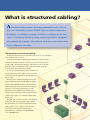

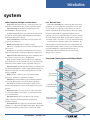
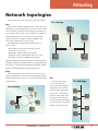

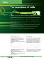
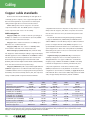
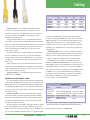
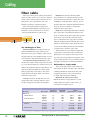

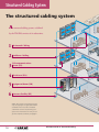
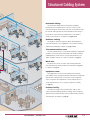
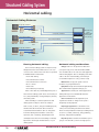

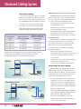

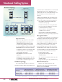
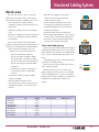
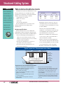
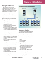
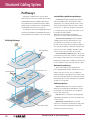


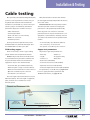
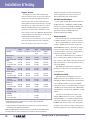
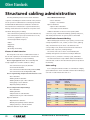
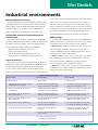
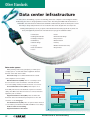
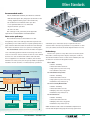
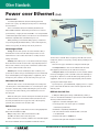
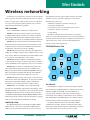


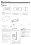
![平成25年9月発行(全文) [PDFファイル/1.41MB]](http://vs1.manualzilla.com/store/data/006623446_2-9a857bfc08b65df51095a2f4ed45f134-150x150.png)