1
BOSCH DISHWASHERS
SHI4302/4306/66A05/6802/6805/6806
SHU3002/3006/3012/3016
SHU3026/3032/3035/3036
SHU33A02/06, 3302/3305/3306/3307
SHU3322/3326/3336, 4322/4326
SHU4002/4006/4016/4022/4026/4036
SHU43C02/05/06/07, 43E02/05/06/07
SHU4302/4304/4306/4312/4314/4316
SHU53A02/05/06, 53E02/05/06
SHU5302/5304/5305/5306/5307
SHU5312/5314/5315/5316/5317
SHU66C02/05/06/07, 66E02/05/06/07
SHU6802/6805/6806
SHU8802/8805/8806/8812/8815/8816
SHU9902/9905/9906
SHU9912/9915/9916/9922/9925/9926
SHU9952/9955/9956
SHV4303/46C03/4803/66A03/6803/99A03
SHX33A02/05/06, 43E02/05/06
SHX46A02/05/06/07, 46B02/05/06/07
SHX56B02/05/06, 99B05/06
SHY56A02/05/06, 66C02/05/06, 99A02/05/06
0
Table of Contents
I.
Safety Concerns………………………..……….…..…………... 2
II.
Product Line Related…………………………………..……….. 2
III.
Product Specific………………………………………………… 3
IV.
Installation Issues…………………….………………..…….…. 6
V.
Theory of Operation…………………………………..………. 22
VI.
Component Access/Replacement………………..………… 31
VII.
Component Testing/Test Procedures……………..………. 59
VIII.
Troubleshooting…………………………………….………… 62
IX.
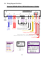
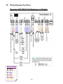
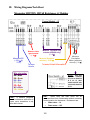
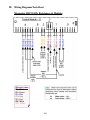
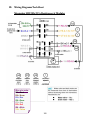
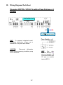
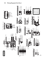
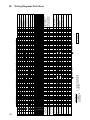
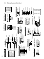
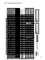
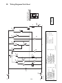
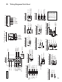
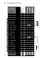
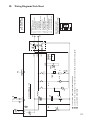
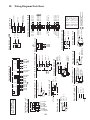
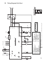
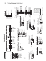
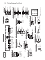
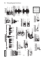
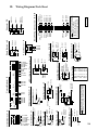
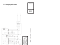
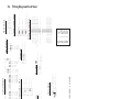
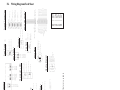
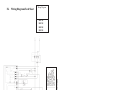
Wiring Diagrams/Tech Sheet…………………….………….. 96
1
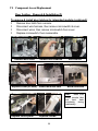
I. Safety Concerns
IA. Safety Symbol Explanation
m = Warning symbol included in Installation Instructions and on this page. It includes serious warnings
such as injury or death, electric shock & dishwasher damage.
IB. Identify Potential Hazards
There are few hazards associated with dishwashers. Two possible hazards are:
m Electrical shock hazard (as with any electrical appliance).
m Sharp edges – only on tank when sump is removed and on inner door when dispenser is removed.
IC. Warning Personal Injury
m Danger of electric shock. Disconnect power before disassembling or working on dishwashers. Make
sure dishwashers are electrically grounded. Use only copper conductors for all wiring or rewiring.
ID. Warning Property Damage
Only warning on property damage comes from improper water connections – overly tightened water
connections could cause water to leak from water inlet valves. This only applies to older models with water
inlet valves with vertical solenoids (coils). Newer models with water inlet valves with horizontal solenoids
(coils) have water connections integrated with mounting brackets to eliminate possibility of damaging valves
from overtightening water fittings.
IE. Electrostatic Sensitive Devices
None since all control modules have pc boards mounted in plastic housings – no pc boards are handled in
repairing dishwashers.
II. Product Line Related
IIA. CFC Information
There are no CFC’s or any other refrigerant used in dishwashers.
IIB. Emissions Related
There are no emissions related to dishwashers. Occasionally smells come from customer drains into
dishwashers if dishwashers weren’t properly connected to drains.
IIC. CO
No carbon monoxide is emitted by dishwashers.
IID. Government Compliance Issues
None.
IIE. Certification Requirements
All dishwashers are designed, tested and certified by UL for use in the U.S. and Canada. In addition, all
dishwashers are Energy Star certified as energy savers. Many dishwashers have NSF sanitized wash
cycles.
2
III. Product Specific
IIIA. Product Specification Chart
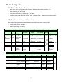
Rated 120V, 60 Hz, 15A, 1450W (max.). Maximum amp draw when heaters running ~ 11A.
Water connection 3/8” NPT female.
Inlet water pressure range 5 - 120 psi (0.3 – 8.27 bars).
Circulation pump motor rated 120V, 60 Hz, 160W, insulation class A. Motors are thermally protected
and use a 10µF capacitor.
Drain pump rated 120V, 60 Hz, 35W, 0.85A.
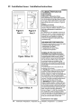
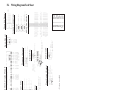
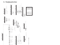
IIIB. Model Number Listing and Explanation
Model numbers were changed with the dishwashers introduced during the 4th quarter of 2002.
Current model # listing – see below
Older model # listing – see below
Current Model # Legend
S
V
9
9
A
0
3
Dishwasher
H
Tall
Tub
Type
# Wash
Programs
Control
Sold Through
Dummy
#
Color
UC/#
1
2
3
4
5
6
7
8
9
S=
Dishwasher
U=
H = Tall Undercounter,
Tub
standard
9 = Automatic 0 = Mechanical
V = Fully
integrated
6 = Six
3 = Electronic
6 = Electronic +
Options
X = Integra I
5 = Five
Y = Integra II 4 = Four
9 = Automatic
I = Semi
Integrated
3 = Three
A = Distribution
P
L
A
C
E
B = Sears
C = Common
D = Builder
H
O
L
D
E
R
E = Other
2 = White
5=
Stainless
CSI
6 = Black
7 = Biscuit
3 = N/A,
Fully
Integrated
Old Model # Legend
S
H
Dishwasher Tall Tub
1
2
S=
H = Tall
Dishwasher Tub
V
Type
6
8
0
# Wash Programs
Control
Level
3
Color
UC/#
3
4
5
6
7
8
U = Undercounter,
standard
9 = Integra I (four)
or II (five)
0 = Mechanical
3, 8 & 9 =
Electronic
V = Fully integrated 6 = Six
U88xx & U99xx =
Integra I
5 = Five
U995x = Integra II 4 = Four
I = Semi Integrated 3 & 8 = Three
3
0=
Standard
1, 2 & 3
= Deluxe
5=
Integra II
2 = White
3 = N/A, Fully
Integrated
CSI
4=
5=
6=
7=
Almond
Stainless
Black
Biscuit
III. Product Specific
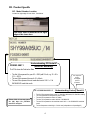
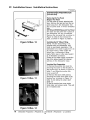
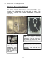
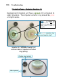
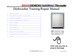
IIIC. Model Number Location
Located on right edge of inner door. See below.
The serial label is fastened to the right
edge of the inner door.
FD8303 00011
Understanding FD Serial #
(used for warranty)
The FD # shows the Fabrication Date
• The first 2 #s represent the year: 83 = 2003 (add 20 to #; e.g. 20 + 83 =
103 → 2003)
• The next 2 #s represent the month: 03 = March
• The next 5 #s represent the unit made that month: 00011 = 11th
SHY99A05UC made that month
10 3 03 0081344 00011 5
Please hold all warranty parts
for (60) days for possible
return for analysis.
•
•
•
•
•
•
This helps the
factory
investigate
product
problems.
Understanding Factory Serial #
The first 2 #’s represent a factory code: 10 = New Bern dishwasher, 82 = New Bern cooking
The 3rd # represents the last digit of the year: 3 = 2003
The next 2 #’s represent the month: 03 = March
The next 7 #’s represent the model: 0081344 = SHY99S05UC
The next 5 #’s represent the unit made that month: 00011 = 11th SHY99A05UC made that
month
The last # represents a check digit = 5 in this case (is dependent on all preceding #’s)
4
III. Product Specific
IIID. Tech Sheet Location
Wiring and circuit diagram folded up and located in slot in front of dishwasher bases.
IIIE. Warranty Information
See below.
Bosch Dishwashers Limited Lifetime Warranty
Statement of Limited Warranty
The warranties provided by BSH Home Appliances ("Bosch") in this Statement of Warranties apply
only to Bosch dishwashers sold to the first using purchaser by Bosch or its authorized dealers,
retailers or service centers in the United States or Canada. The Warranties provided herein are not
transferable, and take place from date of installation or ten business days after delivery date,
whichever comes first.
1 Year Full Limited Warranty
Bosch will repair or replace, free of charge, any component part that proves defective under
conditions of normal home use, labor and shipping costs included. Warranty repair service must be
performed by an authorized Bosch Service Center. All cosmetic defects must be reported within 30
days of installation.
2 Year Limited Warranty
Bosch will provide replacement parts, free of charge, for any component part that proves defective
under conditions of normal home use, shipping costs included, labor charges excluded.
5 Year Limited Warranty On Electronics
Bosch will repair or replace, free of charge, any microprocessor or printed circuit board that proves
defective under conditions of normal home use during the second through fifth year from the date of
original installation, labor charges excluded.
5 Year Limited Warranty On Racks
Bosch will repair or replace, free of charge, the upper or lower dish rack (excluding rack components)
if the rack proves defective under conditions of normal home use during the second through fifth year
from the date of original installation, labor charges excluded.
Lifetime Limited Warranty Against Stainless Steel Rust-Through
Bosch will replace your dishwasher, free of charge, with the same model or a current model that is
equivalent or better in functionality if the inner liner should rust through under conditions of normal
home use, labor charges excluded. Bosch will replace the stainless steel door of any dishwasher if
the door should rust through under conditions of normal home use, labor charges excluded.
For location of nearest repair depot call 11-800800-944944-2904 from 5:00 AM - 5:00 PM MM-F (Pacific time)
5
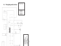
IV. Installation Issues
IVA. Location Requirements
See attached installation instructions.
IVB. Electrical Requirements
See attached installation instructions.
IVC. Water/Drain Requirements
See attached installation instructions.
IVD. Shipping/Packaging Removal
See attached installation instructions.
IVE. Installation Related Process
1.
Leveling cabinet – See attached installation instructions.
2.
Leveling doors – not required for steel doors. For wooden panels added to steel doors,
see installation instructions.
3.
Installing handles – See attached installation instructions.
4.
Door reversal – not possible or necessary.
5.
Quick test procedure
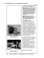
Top Ten Cosmetic/Customer Use/Installation Issues:
Not cleaning sump filters.…Customers often don’t know they exist.
Smelly dishwashers….Often occurs from filters not being cleaned, drain hose high loops
missing or drain gases being present. If all else is OK, then problem can be preservative not purged
from tank door gasket.
Doors leaking or not latching….Usually
Inner door damage.…From
Doors hit toe kicks.…Toe kick installation issue.
an installation issue (dishwasher brackets
installed before dishwashers are leveled front to back, tanks & doors out of square, wooden doors
not drilled accurately). Can be blockage in condensation tubes or having condensation tubes
connected to drain hose air gaps.
upper rack during improper shipping and handling
(dishwashers clamped on wrong sides or dropped).
Junction boxes.…Comes from wires not being connected correctly during installation.
Dispensers.…Customers using too much detergent, not using rinse-aid & not knowing how to
close the door.
Drain hoses not installed properly.…Often no air gap or high loop + pinched hoses -causes poor draining & smelly dishwashers. Most drain pumps are mistakenly replaced for drain
hose installation issues.
Outer doors….Most are dinged during shipment.
Damaged water valves….Primarily from fittings being overtightened.
can allow some water onto kitchen floors.
6
A damaged valve
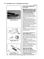
IV. Installation Issues: Installation Instructions
7
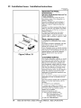
IV. Installation Issues: Installation Instructions
8
IV. Installation Issues: Installation Instructions
9
IV. Installation Issues: Installation Instructions
10
IV. Installation Issues: Installation Instructions
11
IV. Installation Issues: Installation Instructions
12
IV. Installation Issues: Installation Instructions
13
IV. Installation Issues: Installation Instructions
14
IV. Installation Issues: Installation Instructions
15
IV. Installation Issues: Installation Instructions
16
IV. Installation Issues: Installation Instructions
17
IV. Installation Issues: Installation Instructions
18
IV. Installation Issues: Installation Instructions
19
IV. Installation Issues: Installation Instructions
20
IV. Installation Issues: Installation Instructions
21
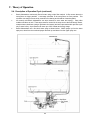
V. Theory of Operation
VA. Description of Operation/Cycle
Bosch dishwashers use separate circulation and drain pumps to reduce overall size, noise, vibration
and energy consumption. This allows the use of tall tanks, increasing overall space inside
dishwashers where full-sized plates can be placed in both upper and lower racks. Circulation pumps
are suspended by rubber straps to further reduce noise and vibration.
Bosch dishwashers use flow-through heaters instead of exposed elements used on most other
dishwashers. Water from spray arms drops to the sump and flows through the circulation pump into
the flow-through heater. Flow-through heaters prevent dishware damage from exposed elements
and allow water to be continuously filtered and heated. Bosch flow-through heaters heat water by
two degrees (ºF) per minute. All heaters are protected by a 185ºF Hi-limit (high temperature cutout)
and by a flow switch which prevents heaters from operating when no water is flowing.
Bosch dishwashers regulate water temperatures using NTC (Negative Temperature Coefficient)
sensors and electronic controls. As water temperatures increase, NTC resistances decrease.
Electronic control modules measure these resistance changes and hold wash and rinse cycles to
tight preset temperatures. Older Bosch mechanical dishwashers use thermostats to regulate water
temperatures.
Bosch dishwashers use condensation drying instead of exposed heating elements. Tanks and inner
doors are coated with bitumen (asphalt compound) which absorbs and retains heat from the heated
wash and rinse water. A condensation tube is connected to a cold zone in the tank which isn’t
covered by bitumen (on right side tank wall for UC/12 & later models and at detergent dispenser on
older UC/06 – UC/11 models). Since the cold zone doesn’t retain heat and is cooler than the areas
coated with bitumen, moisture condenses around it and exits the dishwasher through the
condensation tube. For best results, doors should remain closed until dishwashers have completely
finished drying.
22
V. Theory of Operation
VA. Description of Operation/Cycle (continued)
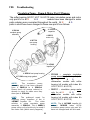
Bosch dishwashers continuously filter all water using a triple filter method. A filter screen above the
sump filters out larger particles. A two-stage microfilter in the sump filters out finer particles. This
microfilter can easily be removed by customers for cleaning and should be cleaned regularly.
All currently sold Bosch dishwashers use aqua sensors to save water and energy – many older
models used them as well. These aqua sensors, located in the sump next to the flow-through heater,
measure water cleanliness (using a light beam and sensor) and add a pre-wash and/or pre-rinse cycle
only if water is dirty. Aqua sensors can save up to 20% of water and energy usage.
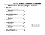
Bosch dishwashers use a four-level water spray as shown below. Water sprays up from the lower
spray arm, down from the overhead sprayer and both up and down from the upper spray arm.
23
V. Theory of Operation
VA. Description of Operation/Cycle (continued)
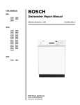
Bosch dishwashers fill with water as shown below.
Normal fill: Water rises to
proper level, pushing air in
pressure chamber which
operates diaphragm.
Overfill: Water rises too high
& operates float switch,
causing drain pump to remove
water from sump.
24
V. Theory of Operation
VB. Description of Components
Circulation pump -- Unlike many dishwashers, Bosch dishwashers use separate circulation and
drain pumps to reduce noise, vibration, space and energy usage. The circulation pump circulates
water from the sump into the spray arms.
Drain pump – The drain pump drains water from the dishwasher. Being a separate pump, it is much
smaller and uses much less energy than a single circulation/drain pump used on other dishwashers.
Impeller – This part of the circulation pump is what drives water throughout the dishwasher. It uses a
precisely manufactured ceramic disk to reduce friction, yet prevent water leaking. This is the part to
replace in rarely used dishwashers if pumps don’t turn.
Flow-through water heater – Unlike most dishwashers, that rely on exposed heating elements in the
bottom of tanks, Bosch dishwashers use flow-through water heaters (that heat ~ 2ºF/minute). This
saves space and allows Tall Tubs (see below), where full-sized plates can be placed in both upper and
lower racks.
NTC – Stands for “Negative Temperature Coefficient”. This temperature sensor in the water heater
provides accurate water temperatures. Its called a “NTC” since its resistance goes down as the water
temperature goes up.
Thermostat – Temperature sensor (and switch) used on older mechanical dishwashers. They open
when temperatures are reached.
Control module – The brain of electronic dishwashers, it receives water temperature values and
controls the entire wash process. It also contains the test program to help diagnose dishwasher
issues.
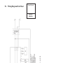
Display module – A separate electronic module with a digital display used on some models.
Float switch – This safety feature shuts down the dishwasher and starts the drain pump if the
dishwasher has gotten excessive water in the base or has overfilled. The drain pump empties out the
sump and hoses, not the base (I.e. the drain pump isn’t a base bilge pump).
Condensation drying – This feature saves energy and enables Bosch dishwashers to have Tall Tubs
– the tallest tubs in the industry, allowing full-sized plate to be placed in both upper and lower racks.
Bitumen insulation around doors and tanks holds heat inside tanks, which forces water vapor out of
tanks before it can condense onto dishes. The area around the condensation tube exit isn’t coated
with bitumen, providing a cold zone for water vapor to condense (instead of on dishes).
Condensation tube – This is part of the genius of condensation drying. It carries moisture out of the
tank while condensation drying is occuring.
Detergent & rinse-aid dispenser – This dispenses detergent and rinse-aid at just the right times. In
older dishwashers (service indexes UC/06 & UC/11), it attached to the condensation tube (in the door).
Aqua sensor (Sensotronic) – This sends a beam of light through water in the heater and measures
how clean the water is. Depending on water cleanliness, rinses are omitted, saving time & energy.
Microfilter and filter screen – Unlike other dishwashers, the water in Bosch dishwashers is
continuously filtered (100% of the time). The filter screen traps large food chunks while the two or
three stage microfilter (depending on model) filters out small food particles.
Softer bearing – Used to describe circulation pump mounting system using rubber straps to further
reduce noise and vibration (on UC/11 & later models). Sumps and heaters were changed as well as
circulation pumps. Older models (UC/06, UC/07 & UC/09) had pumps mounted on rubber bushings.
Tall tubs – This distinctive feature allows full-sized plates (~ 10”) to be placed in upper racks. The
tallest tanks in the industry is made possible by separate pumps, condensation drying and good use of
space in the dishwasher base.
Water inlet valve – Water valve which turns on and off to allow water into the dishwasher.
Water inlet system (with fill switch and diaphragm) -- It insures dishwashers fill properly at various
incoming pressures. It uses a air pressure diaphragm and fill (micro) switch to alert the dishwasher
control module when the proper amount of water has filled the dishwasher.
25
V. Theory of Operation
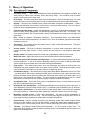
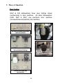
Dispensers
During each wash program, the wax motor opens twice -once to dispense detergent and again to dispense rinse-aid.
The wax motor opens the same way -- the linkages make the
separate compartments open.
NOTE: The white plastic linkage 1st opens the detergent dispenser door, then
cocks in place to dispense rinse-aid when the wax motor operates the 2nd time.
After the 2nd operation, the linkage resets itself so it will open the dispenser
detergent door for the next wash program.
Condensation
tube (for vented
dispenser)
26
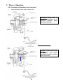
V. Theory of Operation
Top Rack Only
Models with the Top Rack Only feature have separate
actuators mounted underneath heater assemblies. The
actuator moves a magnetic plunger in the lower rack
heater port, diverting water to the top rack.
Plunger
Heater with top rack actuator
Both racks
Top rack only
Where plunger engages sump
UC/11 heater
UC/06 heater
HINT: Do not use softer
bearing heater assemblies
(UC/11 & later) on older
UC/06 models since the
sump, circulation pump, base
and heater clamps/gaskets
have to be replaced as well
for the heaters to fit.
HINT: Models with water switches and
Top Rack Only have the Top Rack Only
parts integrated with the water switches.
No separate actuators are needed.
HINT: Models with water switches and
Top Rack Only have the Top Rack Only
parts integrated with the water switches.
No separate actuators are needed.
27
V. Theory of Operation
Door Latches
SHU & SHI dishwashers have door latches linked
mechanically to door switches. All other dishwashers
(SHV, SHX & SHY) use electronic door switches
(microswitches activated by door latches).
187184 ball bearing door latch
with microswitch
419827 door latch for SHI/SHU
(for mechanical linking)
419828 door latch with
microswitch
28
V. Theory of Operation
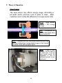
Aqua Sensors
The aqua sensor only affects energy usage, eliminating a
pre-wash and/or pre-rinse cycle if water is clean. Most
customers won’t notice the difference if an aqua sensor fails.
NOTE:
Aqua sensors
provide ~ 20% energy
savings.
HINT: Dishwashers still
operate adequately when
aqua sensors fail.
HINT: Customers will only notice aqua sensors failing if they
see their dishwashers running slightly longer or their electric
and water usage getting slightly higher.
NOTE: If water is clean
enough, it will be kept for
the wash cycle. If not, the
aqua sensor directs the
dishwasher to add an
additional pre-rinse or prewash cycle.
29
V. Theory of Operation
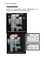
Water Fill Assemblies
Water fill assemblies insure dishwashers fill
properly at various incoming pressures.
Diaphragm
Water fill
switch
Switch
lever
Float
switch
Float
Newer water fill assembly without gasket
NOTE:
Older water fill
assemblies
required
a
gasket between the upper
and lower housings. Newer
ones do not require gaskets
and
are
a
drop-in
replacement for older ones.
HINT: Floats should be
checked and bases should
be cleared of water &
debris whenever water fill
assemblies are worked on.
Older water fill assembly with gasket
30
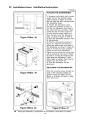
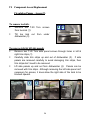
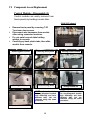
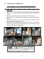
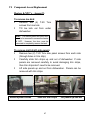
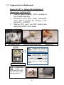
VI. Component Access/Replacement
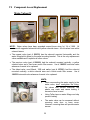
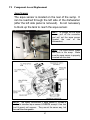
Water Valves (1)
The water valve is accessed from
the front of the dishwasher base
by removing the toe kick.
To remove water valve:
Remove two (2) T-20 Torx screws from toe kick and tilt toe
kick out from under dishwasher.
Remove base insulation (on models with insulation).
Disconnect wires from water valve, including ground wire.
Move sump inlet hose away from water valve (without
disconnecting it).
Remove two (2) T-20 Torx screws from water valve.
Pull valve out from dishwasher and disconnect water hose
from rear of valve. Remove any water from sump & base.
Removing toe kick
Moving sump hose
Removing hose clamp
31
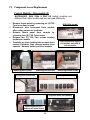
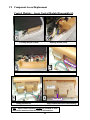
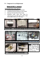
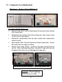
VI. Component Access/Replacement
Water Valves (2)
580009
167081
189533
NOTE: Water valves have been upgraded several times since 1st 1/4 of 1999. All
valves with upgraded solenoids have yellow solenoid stems. All old valves have white
solenoid stems.
The newest valve (part # 189533) has the solenoid mounted horizontally and the
water fitting held in place by the metal mounting bracket. This is the only replacement
valve available and it replaces all other valves.
The previous valve (part # 580009) had the solenoid mounted vertically, a yellow
solenoid stem and a fine brown mesh filter screen. Use # 189533 horizontal valve
whenever it needs to be replaced.
The oldest valve, used March, 1999 and earlier (part # 167081), had the solenoid
mounted vertically, a white solenoid stem and a white mesh filter screen.
189533 horizontal valve whenever it needs to be replaced.
Use #
HINTS:
When reconnecting the water supply to the
water valve, don’t overtighten the fitting.
On valves with vertical solenoids, the
plastic can crack and cause leaking if
excessive force is used.
Using Teflon tape on water fittings can help
prevent leaking.
The water valve can be accessed without
removing outer door or base cover.
However, removing them will provide easier
access.
32
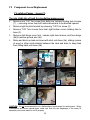
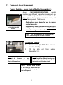
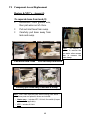
VI. Component Access/Replacement
Circulation Pumps - Access (1)
The circulation pump & capacitor are accessed from the right
side of the dishwasher by removing the right side panel and
blocking the tank.
To remove outer door:
Remove six T-20 Torx inner door screws below fascia panel -- three
per side (1).
Carefully pull bottom of outer door out from dishwasher until top
door tabs clear, then pull door down until it releases from
dishwasher (2). Take care to not scratch outer door.
Remove two plastic door guards (3).
when the outer door is removed.
1
They occasionally fall out
3
2
HINT: The fascia panel and door don’t need to be removed to access
the circulation pump. However, they must be removed to completely
remove the tank.
33
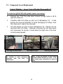
VI. Component Access/Replacement
Circulation Pumps - Access (2)
To remove toe kick:
Remove two T-20 Torx screws
from toe kick (1).
Tilt toe kick out
dishwasher (2).
from
1 2
under
To remove right & left side panels:
Remove two T-20 Torx side panel screws through holes in left &
right trim strips (1).
Carefully slide trim strips up and out of dishwasher (2). If side
panels are removed carefully to avoid damaging trim strips, then
trim strips don’t need to be removed.
Lift side panels up and out from dishwasher (3). Panels can be
removed with trim strips. Although removing the left side panel isn’t
necessary for access, it does allow the right side of the tank to be
blocked upward.
1
3
2
34
VI. Component Access/Replacement
Circulation Pumps - Access (3)
To raise right side of tank for circulation pump access:
Remove one T-20 Torx screw from both rear corners holding tank to base
(1) -- removing screw from both sides allows tank to be blocked upward.
Remove right toe kick bracket by removing T-20 Torx screw (2).
Remove T-20 Torx screws from front right bottom corner holding tank to
base (3).
Remove right hinge cover (4a), release right door tension cord from hinge
(4b) & remove ground wire (4c).
Raise and block up tank as shown with strut onto base (5a), sliding a piece
of wood or other solid material between the tank and base to keep tank
from falling back onto base (5b).
Screw
1
2
3
4a
4b
4c
5a
5b
CAUTION: Its not recommended to turn dishwashers upside-down for tank access. When
dishwashers are turned upside-down, water can flow into the diaphragm of the water fill
assembly and cause water to not fill properly.
35
VI. Component Access/Replacement
Circulation Pumps - Disassembly
To remove motor to access impeller or change complete pump:
Disconnect wire
connections (1).
For UC/11 & later models with softer bearing, lift up rubber straps
from both sides of motor (2). For older models, lift motor up from
base.
To release plastic latch on pump/motor housing, carefully push onto
latch with screwdriver (3).
To release motor from pump housing, twist motor to the right
(clockwise). Some force may be required. Capacitor should be ~
11:00 position (4). Pull motor out from pump housing.
harness
from
1
motor
after
carefully
noting
2
3
Latch
4
CAUTION:
Don’t grab
motor next to capacitor to
avoid jamming your hand
on the capacitor.
HINT: When replacing complete circulation pumps for
softer bearing models (UC/11 & later), reusing existing
front pump housings (& discarding replacement
housings) can save time by not having to change hose
clamps. If desired, order # 172272 hose clamps &
replace entire pumps.
36
VI. Component Access/Replacement
Circulation Pumps - Reassembly
To remove & install impeller (using kit # 167085):
While holding motor fan so shaft won’t spin (1a), unscrew impeller
counterclockwise (1b).
Rotate pump housing counterclockwise until tabs clear, then lift
housing from motor (2).
Remove spring and O-ring from pump housing, then lift spacer up
from motor shaft (3).
Place replacement spacer onto motor shaft (4). Note larger end
goes onto shaft 1st.
Install replacement spring & O-ring onto pump housing, then line up
housing-motor tabs to screw pump housing onto motor (5a). Screw
replacement impeller onto motor shaft (5b).
Align motor to pump housing with capacitor @ 11:00 position to
facilitate reassembly.
Motor fan
1a
1b
3
2
5a 5b
37
4
VI. Component Access/Replacement
Control Modules - Disassembly (1)
Control modules are easily removed from
fascia panels by bending console tabs.
(SHU 9922 shown)
Remove fascia panel by removing T-20
Torx inner door screws.
Disconnect wire harnesses from module
after noting connector locations.
Pry out metal console tabs holding
module to console.
Carefully pry back plastic tabs, then slide
module from console.
Removing door screws
Bending back tabs
Removing fascia panel
Disconnecting wires
NOTE:
Control modules
for non-integrated models
look differently and have
different tabs, but are
removed using the same
procedure.
Console without module
38
Viewing control module
Sliding module out
NOTE:
Control modules
for non-integrated models
look differently and have
different tabs, but are
removed using the same
procedure.
VI. Component Access/Replacement
Control Modules - Disassembly (2)
SHY56A/66C, SHU 995x & SHV 68 control modules are
different than other models and are removed differently.
Remove fascia panel by removing six (6)T-20
Torx inner door screws.
Disconnect wire harnesses from module
after noting connector locations.
Remove fascia panel from console by
removing four (4) T-20 Torx screws.
Remove two (2) T-20 Torx screws holding
module to console.
Carefully pry back locking tabs on each front
corner of module, then remove module from
console. Remove button pad from module.
Removing door screws
Removing fascia screws
Prying back module tabs
(SHU 995x shown)
These instructions apply to
SHY56A/66C, SHU 995x &
SHV 68 models.
Removing module screws
Sliding module out
Align tabs when reassembling
Removing button pad -buttons can come off pad
39
VI. Component Access/Replacement
Control Modules - SHY56A/66C Control Modules with Displays
SHY56A/66C control modules have separate
modules mounted on the front of fascia panels.
display
To remove/install display module:
Remove outer door & fascia panel.
Confirm the (4) pushbutton carrier display
These instructions apply to
SHY56A & SHY66C models.
latches are intact.
Route display wire harness through (door
latch) console opening, press harness onto
pushbutton carrier wire guide & connect
terminal.
Insert display into top latches (on
pushbutton carrier), then push bottom of
display up and rotate it into bottom latches.
wire guide
3
2
1
latches
Removing door & fascia
Checking display latches
4
Locking display in place
40
Connecting wire harness
VI. Component Access/Replacement
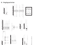
Control Modules – Apexx Control Module Disassembly (1)
Apexx
(SHV99A/SHX99B/SHY99A)
control
modules are different than other models and are
removed differently. Modules are mounted on the
base (where base wiring connectors were), not
behind fascia panels. This means:
These instructions apply
to SHV/SHX/SHY99A
models.
• Dishwashers must be pulled out to change
control modules.
• Dishwashers must be pulled out to measure
voltages & resistances -- dishwashers
cannot be diagnosed from the front.
HINT: Its not necessary to remove outer
doors to access Apexx control modules.
1 2
To remove toe kick:
Remove two (2) T-20 Torx screws
from toe kick (1).
Tilt toe kick
dishwasher (2).
HINT:
Apexx control modules
cannot be checked or have
resistances measured from the
front of dishwashers.
out
from
under
HINT: It may be possible to reach
behind modules without blocking up
tanks.
If not, then follow these
instructions to block up tanks.
NOTE: Modules were moved
to the base to make room for
the larger full text displays in
the fascia panel.
41
VI. Component Access/Replacement
Control Modules – Apexx Control Module Disassembly (2)
To remove right & left side panels (where necessary):
Remove two T-20 Torx side panel screws through holes in left &
right trim strips (1).
Carefully slide trim strips up and out of dishwasher (2). If side
panels are removed carefully to avoid damaging trim strips, then
trim strips don’t need to be removed.
Lift side panels up and out from dishwasher (3). Panels can be
removed with trim strips. Although removing the left side panel
isn’t necessary for access, it does allow the right side of the tank
to be blocked upward.
1
Removing trim strip screws
2
3
Removing trim strips
HINT: Apexx control modules cannot
be checked or have resistances
measured
from
the
front
of
dishwashers.
Removing side panels
HINT: It may be possible to reach behind
modules without blocking up tanks. If not,
then follow these instructions to block up
tanks.
42
VI. Component Access/Replacement
Control Modules – Apexx Control Module Disassembly (3)
To raise right side of tank for Apexx module access (where
necessary):
Remove one T-20 Torx screw from both rear corners holding tank to
base (1) -- removing screw from both sides allows tank to be blocked
upward.
Remove right toe kick bracket by removing T-20 Torx screw (2).
Remove T-20 Torx screws from front right bottom corner holding tank to
base (3).
Remove right hinge cover (4a), release right door tension cord from
hinge (4b) & remove ground wire (4c).
Raise and block up tank as shown with strut onto base (5a), sliding a
piece of wood or other solid material between the tank and base to keep
tank from falling back onto base (5b).
Screw
1
2
4b
4c
3
5a
4a
5b
CAUTION:
Its not recommended to turn dishwashers
upside-down for tank access. When dishwashers are turned
upside-down, water can flow into the diaphragm of the water
fill assembly and cause water to not fill properly.
43
VI. Component Access/Replacement
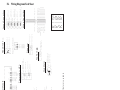
Control Modules – Apexx Control Module Disassembly (4)
1
2
Locating module in base
Opening module cover
Pu
sh
4
3
Disconnecting module terminals
6
5
Sliding module out
lat
c
hl
eft
Pushing back module latch
Note latch
Align module tabs when reassembling
HINT: Apexx control modules cannot be checked or have
resistances measured from the front of dishwashers.
44
VI. Component Access/Replacement
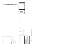
Control Modules – Apexx Display Module Disassembly
Apexx (SHV99A/SHX99B/SHY99A) display modules are mounted on
fascia panels (where control modules are mounted on other models).
These instructions apply to
SHV/SHX/SHY99A models.
front
top
Removing wire harness
Removing
fascia screws
1
2
Removing display module
NOTE:
Control
modules were moved to
the base to make room
for the larger full text
displays in the fascia
panel.
3
45
VI. Component Access/Replacement
Heater s & NTC’s – Access (1)
The heater & NTC can be accessed or measured from
the right side of the dishwasher, but can only be removed
by dropping the entire base (by flipping the dishwasher
on its back) since they are wedged underneath the tank.
To remove outer door:
Remove six (6) T-20 Torx screws from inner door below
fascia panel (three (3) per side).
Carefully pull bottom of outer door out from dishwasher until
top door tabs clear, then pull door down until it releases
from dishwasher. Take care to not scratch outer door.
Remove two (2) plastic door guards. They can fall out when
the outer door is removed.
Remove inner door screws
Slide out outer door
Remove door guards
HINT: Remove all water from the sump and hoses before accessing the heater -when the dishwasher is flipped on its back, water can enter the water fill assembly
diaphragm and cause the dishwasher to not fill properly.
46
VI. Component Access/Replacement
Heaters & NTC’s – Access (2)
To remove toe kick:
Remove two (2) T-20 Torx
screws from toe kick.
Tilt toe kick out from under
dishwasher.
HINT: The fascia panel and door don’t
need to be removed to access the heater
& NTC. However, the door must be
removed to completely remove the tank.
To remove right & left side panels:
Remove two (2) T-20 Torx side panel screws from each side
(through holes in trim strip).
Carefully slide trim strips up and out of dishwasher. If side
panels are removed carefully to avoid damaging trim strips,
then trim strips don’t need to be removed.
Lift side panels up and out from dishwasher. Panels can be
removed with trim strips.
Remove panel screws
Slide out trim strips
47
Lift panels up and out
VI. Component Access/Replacement
Heaters & NTC’s – Access (3)
To separate base from tank (1):
Carefully lay dishwasher on its back.
Carefully pull door springs out from base.
Remove terminal blocks from base.
Separate water valve from base by
removing two (2) T-20 Torx screws, then
move water valve out of the way.
Place on back
Pull out door springs from base & disconnect cords
Disconnect door spring cords, then remove terminal blocks from base
HINT:
Remove water
from sump and hoses
before laying dishwasher
on its back (to avoid
water entering water fill
assembly & causing
faulty water filling).
Disconnect water valve from base
48
VI. Component Access/Replacement
Heaters & NTC’s – Access (4)
To separate base from tank (2):
Disconnect J-box ground wire,
then pull wires out of J-box.
Pull out inlet hose from sump.
Carefully pull base away from
tank and sump.
HINT: Its simpler &
quicker to remove the
two water valve screws
than to remove the
hose clamp.
Pull wires from J-box
Pull out sump inlet hose
Carefully pull base away from tank & sump
HINT: Don’t order duplicate parts when ordering parts below -when these parts are replaced, others are included:
• Heater assy. -- includes NTC, Hi-Limit, flow switch (& aqua
sensor where applicable).
• NTC -- includes Hi-Limit.
49
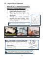
VI. Component Access/Replacement
Heaters & NTC’s – Removal & Installation (1)
Removing & Installing Heater & NTC:
Remove two (2) T-20 Torx screws
holding heater assembly to sump.
Disconnect wires from heater, flow
switch, NTC & Hi-Limit after noting
connections.
Pull clips, then carefully pull heater
assembly from sump & pump. Note
heater comes as an assembly (with
housing & gasket).
HINT: If needed, use rinse-aid to lubricate gaskets to make
it easier to assemble heater to sump and pump.
NOTE: Softer bearing &
non-softer
bearing
heater
assemblies,
circulation pumps and
sumps cannot be mixed
and matched.
Softer
bearing heaters don’t fit
in older models and
older heaters don’t fit in
softer bearing models.
Pull clips
Heater assembly
Remove heater screws
Remove heater
NOTE:
Softer bearing & non-softer bearing heater
assemblies are connected to circulation pumps differently:
• Softer bearing models (UC/11 & above) have gasket
assembled to heater and have a separate hose clamp
(order # 172272).
Hose clamp
• Older models (UC/06) have a separate gasket and do
not have a hose clamp.
“Softer
bearing” heater
Heater assemblies contain NTC’s, Hi-Limit’s & flow switches (& aqua
sensors where applicable). If heaters are replaced, these parts are replaced too.
HINT:
50
VI. Component Access/Replacement
Heaters & NTC’s – Removal & Installation (1)
Removing & Installing NTC:
Remove heater assembly -- NTC is located on
top of heater assembly.
Disconnect wires after noting connections
(since NTC & Hi-Limit are included in the
same part -- # 165281).
Remove NTC cover, pull NTC holding tabs
apart and pull NTC out of heater.
Disconnect wires
Remove cover & pull tabs
Hi-Limit
NTC
NTC w/ Hi-Limit
Remove NTC
HINT: If needed, use rinse-aid to
lubricate gaskets to make it easier to
assemble heater to sump and pump.
NOTE: Softer bearing & non-softer
bearing heater assemblies, circulation
pumps and sumps cannot be mixed
and matched. Softer bearing heaters
don’t fit in older models and older
heaters don’t fit in softer bearing
models.
NOTE: To remove flow
switch,
carefully
pry
housing away from switch
(until tabs clear switch),
then snap switch out.
51
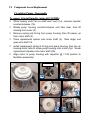
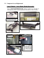
VI. Component Access/Replacement
Drain Pumps – Removal & Installation
Drain pumps are mounted to sumps in the front of
dishwashers -- they’re easily accessible from the front of
dishwashers by removing toe kicks.
Removing & installing drain pump:
Remove toe kick, then pull up
terminal cover and disconnect
wires. For easier access, remove
base cover 1st.
To remove pump, push latch (on
circular collar) & rotate pump
clockwise (cw). To install new
pump, insert @ 2:00 position &
rotate counterclockwise (ccw).
Clean water & debris from base,
then check float operation.
Connect wires, then install base
cover & toe kick.
HINT: Improper installation issues causing
dishwashers to not drain properly -- its
usually not a drain pump problem:
Drain hoses without high loops or
drains without air gaps
Drain hoses > 10’ long (i.e. > 4’
extension)
Drain
hoses
kinked
when
dishwashers installed under cabinets
NOTE: Standard 6-vane drain pumps (#
167082) are quieter and smoother than 4vane pumps.
Drain pumps used in
installations (in Washington State) with
Johnson Tees must use stronger 4-vane
pumps (# 184178). 4-vane pumps will be
slightly noisier, which is normal.
52
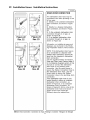
DRAIN HOSE INSTALLATION TIPS:
Must have drain hoses with high
loops or drains with air gaps.
Drain hoses can be up to 10’ long
– can add up to 4’ to dishwasher
hose.
Secure drain hoses to rear of
dishwashers
with
non-metal
bands.
VI. Component Access/Replacement
Dispensers – Removal & Installation (1)
To remove/install dispensers:
Remove outer door, remove fascia panel & disconnect wire harness
from fascia panel.
Disconnect wire harness from above dispenser, then remove wires
to wax motor & reed switch.
Disconnect condensation tube (for older models with condensation
tubes in doors).
Bend retainer tabs, the push dispenser inward toward tank. Protect
hand with towel as edges are sharp.
Replace from inside of tank -- position O-ring seal and bend tabs to
secure. When replacing dispensers, lubricate O-rings with rinse-aid
& support inner doors to avoid damage if O-rings stick.
Disconnecting wire harness
Bending retainer tabs
CAUTION: Inner door edges are
sharp! Cover door edges and
remove dispenser carefully.
53
VI. Component Access/Replacement
Dispensers – Removal & Installation (2)
For UC/12 and later dishwashers, condensation tubes were
moved (from dispensers) to the right side of tanks. This
required a change from vented dispensers to unvented
dispensers.
Condensation tube
HINT: Vented dispensers cannot be
used
to
replace
unvented
dispensers. If they are, dishes won’t
dry properly and there can be water
leaking inside dishwasher doors.
HINT: There are a limited number of
UC/11 dishwashers with condensation
tubes in tanks and with unvented
dispensers.
Treat them like UC/12
dishwashers.
HINT: UC/12 model
condensation
tubes
exit in the base behind
the sump. There is no
drain connection for
these tubes.
54
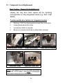
VI. Component Access/Replacement
Door Latches – Removal & Installation (1)
Usually the only door latch repairs will be replacing
microswitches on fully integrated models (e.g. SHV, SHU
88/99).
To disassemble door latches for integrated models:
Remove T-20 Torx fascia panel screws from inner door.
Lower fascia panel from door.
Locate door latch in console.
Bend out console metal tabs to allow latch removal.
Remove panel screws
Tabs (inner view)
Lower fascia panel
Bend out metal tabs
NOTE: Door latches for UC/14 & up models are different
than UC/06 - UC/12 models -- they cannot be interchanged.
Must replace strike plate & door latch together.
55
Door latch in console
VI. Component Access/Replacement
Door Latches – Removal & Installation (2)
To remove & install door latches for integrated models (continued):
Remove door latch from console.
Disconnect wire harness, then remove microswitch & cover.
Disconnect wires, then remove microswitch from cover.
Replace microswitch, then reassemble.
Remove door latch
Replace cover (in slots)
Remove microswitch
Insert latch into tabs
Microswitch
Bend tabs back
HINT:
Make sure
metal console tabs
are
bent
back
completely
during
reassembly.
Replace fascia panel
Replace screws
56
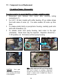
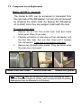
VI. Component Access/Replacement
Aqua Sensors
The aqua sensor is located on the rear of the sump. It
can be reached through the left side of the dishwasher
(after the left side panel is removed). Its not necessary
to block up the tank to reach the aqua sensor.
Tank
Sump
HINT: To change out the aqua
sensor, pull off the connector
and pull out the aqua sensor
(toward the rear of the
dishwasher).
Base
HINT: The aqua sensor slides
into slots in the sump. Make
sure the aqua sensor is properly
inserted into the slots.
NOTE: The Apexx Sensotronic 2 aqua sensor # 175340 is
similar to standard aqua sensor # 165279, except it has two
(red & green) soil sensors. They mount the same way, but
are not interchangeable.
57
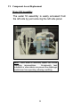
VI. Component Access/Replacement
Water Fill Assemblies
The water fill assembly is easily accessed from
the left side by just removing the left side panel.
HINT: Most water fill assembly repairs will involve
replacing microswitches.
Occasionally tank
insulation or other debris can prevent the diaphragm
switch lever from operating, allowing overfilling.
58
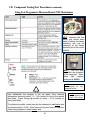
VII. Component Testing/Test Procedures
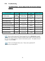
Using Test Programs
Using test programs for various models (UC/06 - UC/14)
Models
Buttons to Enter Test Program
SHU/SHI430x, SHU431x
Power Scrub Plus + Regular Wash
SHU33/DLX
Power Scrub Plus + Rinse & Hold
SHU43C, SL34A, SHU432x
Regular Wash + Rinse & Hold
SHU53/66C/68, SHI66A/68
Scrub Wash + Delicate/Econo
SHU53A, SHX/SHY56, SL95A
Regular Wash + Quick Wash
SHU88
Power Scrub Plus + Quick Wash
SHU990x, SHV43/48
Power Scrub Plus + Regular Wash
SHU991x (thru UC/11)
Power Scrub Plus + Quick Wash
SHU991x (UC/12), SHU992x
Power Scrub Plus + Delicate/Econo
SHU995x
Regular Wash + Delicate Wash
SHV46C, SL84A, SHX43E/ 46A-B Power Scrub + Delicate/Econo
SHV66A, SHY66A
Scrub Wash + Delicate/Econo
SHV68
Scrub Wash + Regular Wash
SHV99, SHX99, SHY99
(2) left buttons (see below)
SHX33A
Power Scrub + Rinse & Hold
GI976/966, GM276
Intensive + Delicate
DW44
Heavy Wash + Light Wash
To enter test programs, hold down buttons above (2nd & 4th from left), then
turn dishwasher on by pushing on/off button. Push buttons above a 2nd
time to start test program. Allow program to finish to see fault codes. Turn
dishwasher off to exit test program.
To enter SHV/X/Y99 test program, open door, hold down 2 left buttons &
turn dishwasher on by pushing on/off button. Press “+” button repeatedly
until "S-3-" shows on display, then push start button to check faults on last
8 washes. Close door to begin test program. Allow program to finish to
see fault codes. Push “-” button to skip test steps. Turn dishwasher off to
exit test program. Choose “S-6-” to clear fault codes.
HINT: Dishwasher test programs heat water to 150ºF, so test
programs will generally run > 20 minutes for incoming water
temperatures ~ 120ºF.
NOTE: Flow through
heaters heat water ~
2ºF / minute.
HINT:
Open door to select test
program for fully-integrated models,
then close door to run program.
59
VII. Component Testing/Test Procedures (continued)
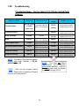
Fault Codes
DISHWASHER TEST PROGRAM ERROR CODES (on 2-digit digital displays):
#
#
#
#
#
#
00
0 – No faults
1 – Aqua Sensor (Sensotronic) fault
2 – Heating system fault (heater, Hi-Limit, flow switch, NTC, control module heater relay)
4 – Water filling fault
TIP: Fault codes add up for multiple faults
8 – NTC (temperature sensor) fault
(e.g. heating + water filling fault = 2 + 4 = 6)
16 – Water switch fault
DISHWASHER CUSTOMER USE ERROR CODES (on 2-digit digital displays):
# F – Water filling fault (underfill, overfill or water in the base)
# 2H – Last wash cycle too long (> 99 minutes). Can be cold inlet water or heating
system fault (heater, Hi-Limit, flow switch, NTC, control module heater relay).
# _h – Delay Start feature (not a fault code)
DISHWASHER TEST PROGRAM
ERROR CODES (on lower line of
full text Apexx SH_99 displays):
#S3 – No faults
#A – Aqua Sensor (red) fault
#B – Aqua Sensor (green) fault
#E – Water switch fault (no pulses
detected)
#F – Water filling fault
#G – Water switch fault (won’t stop
running)
#H – Heating system fault (heater,
Hi-Limit, flow switch, NTC, control
module heater relay)
#K – NTC fault (short-circuited or
open-circuited)
#xx – Test program step count
(testing done when = 00)
TIP: Top line shows wash cycle &
bottom line shows fault code.
HINT: Dishwasher test programs heat
water to 150ºF, so test programs will
generally run > 20 minutes for incoming
water temperatures ~ 120ºF.
Selecting test
program
Checking fault
codes
In Cycle
S3
Top
Test program
steps
Front
00
S--3-------- Start 0------- STEP
S3
00
S3
00
HINT: Apexx heater runs
during steps 05 – 08. Press
“-” button to skip to test 05
to measure heater amp draw.
HINT: Open door to select
test
program
for
fullyintegrated models, then close
door to run program.
60
NOTE:
Flow
through heaters
heat water ~ 2ºF /
minute.
VII. Component Testing/Test Procedures (continued)
Using Test Programs to Measure Heater/NTC Resistances
HINT: Because the flow
switch only closes when
water is flowing, the heater
resistance can only be
measured at the heater
terminals (not at the control
module).
HINT:
The NTC and
High Limit are contained
in the same part. When
either
fails,
replace
entire part # 165281.
NOTE: Open door to run
test program for fullyintegrated models.
Use dishwasher test program to fire up heater, then measure
dishwasher incoming current. If ~ 1.5A, heater, Hi-Limit or flow switch
has failed. Check voltage @ module (or timer) -- if 0V, module (or
timer) has failed.
For electronic models, current can also be measured in red heater wire
at control module (~ 9.5A). Since there can be more than one red wire,
check wiring diagram to select heater wire.
61
NOTE:
Flow
through heaters heat
water ~ 2ºF / minute.
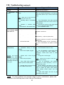
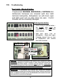
VIII. Troubleshooting
Basic Dishwasher Troubleshooting
Problem
Possible Cause
Suggested Action
Inappropriate
dishwasher
Washability 9
9
problems (dishwasher detergent used.
won't clean properly)
9 Blocked or clogged upper/ lower
spray arms.
9 Water doesn't circulate properly
due to debris in circulation motor
impeller.
Instruct customer to use a powdered
9
dishwasher detergent (e.g. Cascade powder).
9 Check spray arms – clean or replace as
needed.
9 Twist and remove filter, then remove debris
from right side of sump where water enters
circulation pump impeller. If debris has
jammed impeller, turn off and pull out
dishwasher, remove tank, remove circulation
motor and unscrew and clean out imp
HINT : If impeller is damaged, replace entire
impeller assemb ly or it won't seal adequately.
9 Filter not locked down securely, 9 Twist and remove filter, then remove debris
allowing debris to enter sump.
from sump. Instruct customer to twist and
lock filter (cylinder) securely into sump.
CAUTION : Use caution when removing
deb ris from sump to avoid b eing cut b y
sharp deb ris such as aluminum can tab s
or b roken glass.
HINT : Water level will not
affect washab ility as water
fill
is
measured
by
pressure, not time – water
level cannot b e adjusted.
HINT : Due to high temperature rinse (161 o
b reaking down food deb ris and triple filtering
system trapping food deb ris, filters shouldn't
normally clog up. Prob lem often caused b y filter
not b eing securely locked down. Instruct
customer to twist and l
Drain hose behind dishwasher 9 Loop drain hose behind the dishwasher
9
doesn't have an adequate loop.
(with the top of the loop) at least 20" above the
floor.
9 Partially clogged air gap, allowing 9 Unclog sink air gap.
wastewater from prior washes to
circulate in dishwasher.
NOTE : Cleaning sink air gaps is not covered
under warranty.
9 See Water doesn't drain properly on
page xx.
9 Soap doesn't enter dishwasher 9 Turn off dishwasher and test actuator –
due to dispenser actuator (A2 ) failure. replace if faulty.
9
Water doesn't drain properly
HINT : Must pull out dishwasher and HINT : One "wax" motor operates b oth the
remove left side panel to access float detergent and rinse aid dispensers through a
switch.
mechanical linkage. The system always resets
when door closes. Check linkage b y moving it
manually. Check "wax" motor b y running a
continuity check on its terminals.
Suds or foam 9 Too much detergent used.
9 Instruct customer to use less.
9
Instruct customer to use a powdered
remains in dishwasher. 9 Improper detergent used (other 9
than powdered dishwasher detergent). dishwasher detergent (e.g. Cascade powder).
Dishwasher
9
properly.
doesn't
62
drain 9 See Water doesn't drain properly on
page xx.
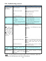
VIII. Troubleshooting (continued)
Problem
Possible Cause
Suggested Action
9 Dishes won't dry 9 Rinse aid not used.
9 Instruct customer on using rinse aid –
dishes won't dry without it.
properly.
Standing water in dishwasher 9 Unclog air gap. Make sure top of drain
Dishwasher has 9
9
sump.
hose loop (behind dishwasher) is at least 20"
an odor.
above floor (add a loop in hose if there isn't
one).
HINT : Water level in sump should b e
at or b elow drain motor cover.
Standing water in dishwasher 9 Turn off dishwasher, drain water manually
9
base.
from dishwasher base and correct source of
water leakage.
Minerals
in
customer
water
9 Recommend customer to get water tested
9
supply.
and use an appropriate water softener.
9 Food debris in dishwasher filters. 9 Clean dishwasher filters.
Dishwasher not turned on.
No power to dishwasher.
9 Turn on/off switch on.
9 Check customer circuit breaker, fuse box
or power connections.
9
Door ajar or on/off switch failed.
9
Door latch has broken.
9
Indicator light failed.
9 Turn off dishwasher and check door or
on/off switch -- adjust or replace them.
9 Turn off dishwasher and replace door latch
– instruct customer to not pull on door without
pulling latch.
9 Run test program to see if light failed. If
so, turn off dishwasher and replace indicator
light.
9 Dishwasher won't 9
run or indicator lights 9
won't come on.
Water doesn't 9 Kink in drain hose.
9 Straighten or replace drain hose.
9
Dishwasher filter(s) or sump 9 Clean dishwasher filters or sump.
drain properly.
9
clogged.
9 Drain motor impeller clogged.
9 Turn off dishwasher, remove drain motor
cover (in sump) and clean impeller. If
necessary, remove drain motor to clean
impeller.
CAUTION : Use caution 9
Kitchen sink or sink air gap 9 Unclog sink or sink air gap.
when removing deb ris clogged.
from sump to avoid b eing 9 Drain motor (m3 ) failed.
NOTE : Cleaning sink air gaps or sinks are not
cut b y sharp deb ris such
covered under warranty.
as aluminum can tab s or 9 Timer (SHU 30/40 models ) or 9
Turn off dishwasher and measure
b roken glass.
module (all other models ) failed.
resistance at motor terminals (≈ 16.5 Ω )
Replace faulty motor.
9 Improper drain connection height 9 Check voltage at and wiring to timer or
(< 20" or 508mm above floor).
module. Turn off dishwasher and replace faulty
timer or module (for SHU/I 43/53 models,
install existing module jumper onto new
module ).
Install drain height and sink air gap
9
according to local codes.
NOTE: For minor problems from improper usage or lack of maintenance, please refer
customer to the Self-Help chart in their Use and Care Manual.
63
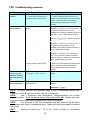
VIII. Troubleshooting (continued)
Problem
9 Dishwasher won't
stop filling or won't
stop draining.
Possible Cause
9 Water in dishwasher base from
leaky or loose hose.
9 Float switch or diaphragm (e6 )
failed.
9 Debris in dishwasher base
activated float switch (e6 ).
9 Low customer water supply
pressure.
9 Inadequate customer water
supply piping.
9 Scale in customer supply piping
or dishwasher piping/parts from hard
water.
9 Adjust customer water supply pressure (to
5-20 psi or 0.3-8.27 bars).
9 Install appropriate piping to dishwasher
according to local codes.
9 Clean or replace clogged piping/parts and
have customer get water tested and use
appropriate water softener.
9 Dishwasher isn't level, causing
float switch (e6 ) to operate.
9 Water fills too
slowly.
Suggested Action
9 Turn off dishwasher, drain water manually
from dishwasher base and reinstall or replace
hose.
9 Level dishwasher using front and rear
leveling legs (see customer dishwasher
installation instructions).
9 Turn off dishwasher and replace float
switch or diaphragm.
9 Turn off dishwasher and remove debris
from dishwasher base
9 Customer water supply turned off 9 Reconnect and turn on customer water
or disconnected.
supply.
NOTE : An "F" fault code 9 Water valve (s2 ) failed.
9 Check resistance @ water valve terminals
in the display shows
(≈ 1000 Ω ). Turn off dishwasher and replace
there's a filling prob lem
faulty valve.
9
Water won't fill.
( not
filling,
over-filling,
underfilling or water in the
base ). The fault code
can't b e reset manually –
it will reset itself 15
minutes
after
the
dishwasher has b een
turned on (aft
9 Turn off dishwasher and replace faulty level
switch.
9 Timer (SHU 30/40 models ) or 9 Check voltage at and wiring to timer or
module (all other models ) failed.
module. Turn off dishwasher and replace faulty
timer or module (for SHU/I 43/53 models,
install existing module jumper onto new
module ).
Water
in
dishwasher
base
9 Turn off dishwasher, drain water manually
9
operated float switch (e6 ).
from dishwasher base, find source of leaking
water and fix water leak.
9
Water level switch (f1 ) failed.
9
9 Detergent or rinse 9 Dispenser actuator (A2 ) failed.
Detergent dispenser door is 9
aid won't dispense 9
jammed.
properly.
Turn off dishwasher and replace actuator.
Free jammed detergent dispenser door.
Turn off dishwasher and replace reed
Refill rinse aid 9 Rinse aid level switch failed (reed 9
9
switch e3 on standard dispensers or switch (standard dispensers) or top-load
light won't come on
built-in
actuator
on
top-load dispenser.
dispensers).
NOTE: For minor problems from improper usage or lack of maintenance, please refer
customer to the Self-Help chart in their Use and Care Manual.
64
VIII. Troubleshooting (continued)
Problem
Possible Cause
9 Water doesn't
circulate.
9 Circulation motor (m2 ) failed.
9 Timer (SHU 30/40 models ) or
module (all other models ) failed.
9 Water doesn’t
heat up properly.
9 Hi-Limit (f5 ) tripped and failed to
reset.
9
NTC (temperature sensor) failed.
9 Turn off dishwasher and check resistance
of NTC (≈ 55 k Ω @ 72oF). Replace faulty NTC.
9
Heater (r1 ) failed.
9 Run test program & measure current to
dishwasher. If current ≈ 11A, heater is OK. If
not (and for all other models), turn off
dishwasher and measure heater resistance (≈
11 Ω ). Replace faulty heater.
9
Water flow switch (e5 ) failed.
9 Run test program & measure current to
dishwasher. If current ≈ 11A, flow switch is
OK. If not, remove flow switch microswitch,
close its contacts & measure its resistance (≈
.4 Ω ). Replace faulty flow switch.
9 Check voltage at and wiring to timer or
module. Turn off dishwasher and replace faulty
timer or module (for SHU/I 43/53 models,
install existing module jumper onto new
module ).
9 Timer (SHU 30/40 models ) or
module (all other models ) failed.
9 Dishwasher cycle
runs too long, yet
dishwasher washes,
rinses and shuts off
OK.
9 Water leaks from
front of dishwasher.
Suggested Action
9 Turn off dishwasher and replace motor.
9 Check voltage at and wiring to timer or
module. Turn off dishwasher and replace faulty
timer or module (for SHU/I 43/53 models,
install existing module jumper onto new
module ).
9 Run test program & measure current to
dishwasher. If current ≈ 11A, Hi-Limit is OK. If
not (and for all other models), turn off
dishwasher and measure resistance @ Hi-Limit
terminals (≈ .3 Ω ). Replace faulty Hi-Limit.
9 Customer hot water supply isn't
hot enough (< 140oF/ 60 oC).
9 Adjust hot water supply according to local
codes.
9 Blocked or clogged upper or
lower spray arms.
9 Excessive foaming.
9 Check spray arms – clean or replace as
needed.
9 See Suds or foam remains in
dishwasher on page xx.
NOTE: For minor problems from improper usage or lack of maintenance, please refer
customer to the Self-Help chart in their Use and Care Manual.
Use a multimeter with temperature, voltage/resistance and current
NOTE:
(ampere) probes. Do all resistance checks with power turned off. Identify each wire
color and location at the control module before looking at this chart.
NOTE:
You will need a T20 Torx screwdriver and may need #1/ #2 flat blade
screwdrivers and a pair of needlenose pliers. Many parts can be snapped out without
using tools.
HINT:
Symbols for parts (e.g. " f3" or "e6 ") refer to those on circuit/wiring
diagrams.
65
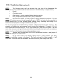
VIII. Troubleshooting (continued)
NOTE:
The following parts can't be serviced from the front of the dishwasher (the
dishwasher must be pulled out and the tank removed or tilted/blocked up to replace them):
•·
Heater
•·
Circulation motor
•·
Aqua sensor – can be reached without blocking up tank
•·
NTC (temperature probe)/Hi-Limit (185ºF) thermostat
On electronic models, run test program to identify dishwasher problems. The test
NOTE:
can run 20 minutes or more (to get temperature up to 150ºF), but tests can be cancelled to
shorten testing time. The test program allows draining, filling, circulating and heating to be
checked more quickly than running a standard wash cycle.
To use test program for troubleshooting, measure voltages/currents as parts come on. For
example, run heating test and measure current coming into dishwasher – if current ≈ 11A, HiLimit, heater and flow switch are OK. If not, check each part to see which one failed. This test
saves time since you can't get to these parts without removing the tank and can't run resistance
checks from front of dishwasher because flow switch stays open.
Jumpers aren't included with SHU/I 43/53 replacement modules – take jumper off
NOTE:
old module and put it on new module.
NOTE:
An "F" fault code in the display shows there's a filling problem (not filling,
overfilling, underfilling or water in the base). The fault code can't be reset manually – it will
reset itself 15 minutes after the dishwasher has been turned on (after testing how it fills).
66
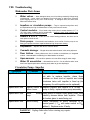
VIII. Troubleshooting
Dishwasher Parts Issues
Water valves…. Most damaged valves occur from being cracked by fittings being
overtightened -- some valves are damaged from hard water or debris from customer
pipes clogging them so they can’t close securely. A damaged valve can allow some
water onto kitchen floors.
Impellers or circulation pumps….They’re
Control modules….From heater relay solder joints to broken buttons to “F” or
improved and perform well,
but expectations are high for dishwashers in rarely used summer homes.
“2H” fault codes, modules can fail occasionally. However, many good modules have
been replaced due to unrelated problems.
Heaters & NTC’s.…Either one can cause heating problems, but there can be
other parts to check as well....
Drain pumps.…Check drain hose installation 1st to confirm if it’s the pump or not.
Many good pumps have been replaced because high loops were missing.
Dispensers.…Repairs often due to customer abuse.
Aqua sensors….Not crucial to operation, but can affect energy & water usage.
Cosmetic damage.…Dinged doors and broken buttons, often during shipment.
Door latches.…Most
problems are due to broken microswitches on integrated
models. Understandable considering how dishwashers are treated.
Water fill assemblies.…Microswitches can fail.
Can be affected when units
have been flipped upside-down, allowing sump water to get into diaphragm.
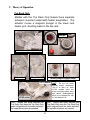
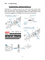
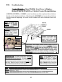
Circulation Pump - Impeller
Symptom
Problem
Solution
Impeller won't turn.
Impeller is frozen. Replace impeller with impeller kit # 167085. If
not able to replace impeller, place 8mm
nutdriver on 8mm stud on impeller and rotate
clockwise twice until impeller is freed up (for
temporary fix until impeller can be replaced).
Impeller won't turn.
Impeller cannot be Replace impeller with impeller kit # 167085. If
broken loose.
pump is faulty, replace entire pump assembly.
Impeller won't turn.
Debris
pump.
Impeller won't turn.
binding Open sump & remove sump pump cover, then
carefully remove debris from impeller. Check
for broken glass to avoid being cut.
Motor is faulty.
Check resistance at motor terminals or at
control panel (~ 7Ω with water switch or 10Ω
without). Replace motor if faulty.
WARNING! Unplug dishwasher before starting any repairs.
67
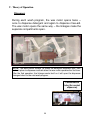
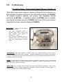
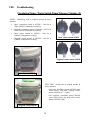
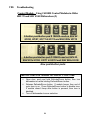
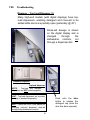
VIII. Troubleshooting
Control Module - Modules Displaying “1”
Occasionally dishwashers will run for hours, not finish washing & show a “1”
in the display. This means the module has timed out due to an unidentified
heating problem -- all heating related parts must be checked until the
problem is found.
IMPORTANT: Whenever a “1” shows in the
module display, the module must be reset (after the
heating problem has been fixed) by running the
dishwasher. The module resets after the 1st run.
START
If no, module
is working
fine.
Has dishwasher
stopped washing
and is showing a
“1” in the
display?
NO
YES
If yes, control
module has timed
out showing
there’s an
unidentified heater
problem.
NOTE:
The heating
problem must be fixed
before the module will
reset and stop showing
a “1” in the display.
Replacing
NTC’s
also
replaces HiLimit’s.
NTC (~ 55kΩ
@72ºF)
Have these
parts been
checked??
Control
module
(heater
relay)
Heater (~ 11Ω)
Replacing heaters also
replaces NTC’s, flow
switches & Hi-Limit’s.
High Limit
(~ 0.3Ω)
Flow Switch
(~ 0.4Ω)
68
Wire
Harness
HINT: Check module heater
relays,
wire
harnesses
/
connections & heaters before
checking NTC’s, flow switches
& high limits.
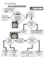
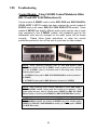
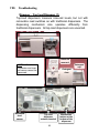
VIII. Troubleshooting
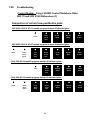
Heater - Troubleshooting Flowchart
NOTE: Flow through heaters
heat water ~ 2ºF / minute.
Can also measure heater
current @ module red
heater wire (~ 9.5A).
If ~ 1.5A,
heater
circuit has
failed.
START
With heater on
(during test
program), measure
dishwasher
incoming current
(black wire).
If ~ 11A,
heater is
working
fine.
Measure
voltage @
control
module.
If ~120 VAC,
check heater
circuit.
Measure
resistance
@ heater
terminals.
If , heater
has failed
(opened).
Replace
heater.
If ~ 0, heater
has failed
(shorted).
Replace
heater.
If ~11 , check
high limit &
flow switch.
If ~ 0 VAC, control module
(heater relay) has failed.
Replace faulty module.
Measure high
limit & flow
switch
resistance.
If high limit ~ 0.3 & flow
switch ~ 0.4 , check wire
harnesses. Replace faulty
harness.
69
If high limit or
flow switch = ,
replace faulty
part.
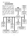
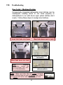
VIII. Troubleshooting
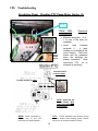
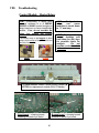
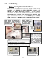
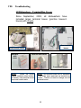
Water Leaking Past Doors
Water seldom leaks out of bottom of
dishwasher doors.
Usually it’s a
customer
or
installation
issue.
Occasionally temporary blockages of
condensation tubes by air pockets
(from standing water in loops) or kinks
in tubes causes leaking. Pressure
builds in tanks, blowing water past
lower
door
seals.
Draining
condensation tubes and straightening
out kinks solves these occasional
problems.
START
Water occasionally
leaks past bottom
of doors, usually at
start of cycles.
Make sure
condensation
tubes aren’t
connected to
drains or air
gaps!
Making sure
bottom end of
condensation
tubes are in
bases
Have these
issues been
checked??
Draining (&
clearing)
condensation
tubes
(including
debris in
bases)
Leveling
dishwashers
before
attaching
undercounter
brackets
Replacing damaged
door seals (including
replacements cut too
short)
Straightening
kinks in
condensation
tubes
Refilling
lower
racks
overfilled
with
dishes
Redrilling
wood doors
to make
dishwasher
doors
square
Curing oversudsing -customer education (too
much soap/rinse-aid or
very soft water)
Moving flexible cutting
boards to left side of
dishwasher
70
VIII. Troubleshooting
Circulation Pump - Checking PTC Pump Motor Starter (1)
The (PTC) circulation pump motor starter (# 182318) is used on SHX99B
/ SHV99A / SHY99A (“Apexx”), & SHX56B / SHV66A / SHY56A-66C
(“ExactWash”) models with water switches. The matching circulation
pump (# 239129) has three slightly smaller & more efficient windings
compared to the traditional pump with two larger windings (# 266511
motor / # 239144 pump). The 3rd (start) winding is cut out when the
motor gets running. This stronger pump is needed due to the increased
water flow resistance from the water switch.
HINT:
PTC
(motor
starter) is located on top
of the pump motor and
can face one of two
directions -- facing out or
facing over the motor.
3 2 4
1
To install (PTC) motor starters,
push female terminals over pump
motor terminals 2 & 4.
The
terminals are different sizes to
match the smaller motor terminal 4.
The (PTC) motor starter helps start the circulation pump. It’s a ceramic thermal
switch which conducts current & heats up, cutting out the 3rd (start) winding at a
preset temperature. The two main windings (with the start/run capacitor) have
power whenever the pump is running.
Check the motor starter if the pump motor won’t start (starter stuck open) or
runs hot (starter stuck closed).
71
VIII. Troubleshooting
Circulation Pump - Checking PTC Pump Motor Starter (2)
PTC
TECH
TIPS:
measurements:
Resistance
Between terminals 1 - 2 is ~
7 Ω (one of the main run
windings).
3 2 4
Won’t
1
help
between
terminals 2 - 4 (start
winding, a run winding & the
motor starter). The motor
starter can’t be measured
since the windings are
always connected.
Must
disconnect PTC 1st to
measure its continuity.
Apexx
model
shown
Terminal located
on motor starter.
Terminal located on motor.
2
3 2 4
1
NOTE: Apexx (SH_99)
models shown. Wire
colors will change for
other models.
NOTE: Unlike standard two-winding pump
motors, these three-winding pump motors
have four terminals instead of three.
NOTE: Motor terminals 2 3 and one of the PTC
terminals are tied together.
72
VIII.
Troubleshooting
Circulation Pump - Water Switch Pump Nuisance Tripping (1)
There have been some nuisance tripping of thermal motor protectors on
three-winding circulation pumps for use with water switches (# 239129).
To prevent nuisance tripping, use pumps with upgraded thermal
protectors (# 437345). If upgraded pumps (# 437345) aren’t available,
use original circulation pumps (# 239129) with new (PTC) motor starters
designed to prevent nuisance tripping (# 423023).
IMPORTANT:
Using new & original
pumps & motor starters:
•
Use “new" circulation pump #
437345 (with 135ºC OVLP) only
with "original" motor starter #
182318 (4.7 – 4.8Ω).
•
Use “original" circulation pump #
239129 (with 120ºC OVLP) only
with "new" motor starter # 423023
(15Ω).
TECH NOTES: New motor starter # 423023 (15Ω) has a larger resistance to limit current
draw through pump motor start windings. Winding temperatures are reduced, but starting
torque is reduced as well. So, new motor starters (# 423023) should never be used with new
circulation pumps (# 437345).
HINTS: Typical repairs will involve either replacing “original" circulation pump # 239129 with
“new" circulation pump # 437345 (preferred) or replacing "original" motor starter # 182318
with "new" motor starter # 423023.
TECH TIPS: All circulation pump motors use auto-reset thermal protectors. Once motor
windings cool below a preset temperature, protectors reset and pumps will work again. If
thermal protectors fail to reset, replace pumps.
73
VIII.
Troubleshooting
Circulation Pump - Water Switch Pump Nuisance Tripping (2)
HINTS: Identifying new & original pumps & motor
starters:
•
“New" circulation pump # 437345 – look for #
“5600 060022” stamped on housing.
•
“Original" circulation pump # 239129 – look for #
“5600 050139” stamped on housing.
•
“New" motor starter # 423023 – look for #
“041692” stamped on housing.
•
“Original" motor starter # 182318 – look for #
“036906” stamped on housing.
“New” motor starter 423023
“Original” motor starter 182318
“New” pump 437345
TECH TIPS: Using new & original pumps &
motor starters:
Use “new" circulation pump 437345 (with
135ºC OVLP) only with "original" motor
starter 182318 (4.7 – 4.8Ω).
Use “original" circulation pump 239129
(with 120ºC OVLP) only with "new" motor
starter 423023 (15Ω).
“Original” pump 239129
74
VIII.
Troubleshooting
Circulation Pump – Replacing Impellers (1)
Occasionally, a circulation pump impeller can stick if a dishwasher hasn’t been used for a
long time. Impeller ceramic rings and carbon rings had been changed (during January,
2001) to reduce or eliminate impeller sticking (ceramic rings are located around shaft on
rear of impeller).
For temporary repairs when impeller replacement isn’t possible, impellers can be loosened
by rotating them (through the sump) using an 8mm nut driver (impellers should be replaced
shortly thereafter when repairs are possible).
8 mm nutdriver
HINTS:
Upgraded impellers (with upgraded
Sump
Impeller
Access port to
impeller through
sump
INSTRUCTIONS
IMPELLER:
FOR
LOOSENING
ceramic rings) and carbon rings fit
both old 263835 and new 266511
(softer bearing) circulation pump
motors (and corresponding pump
housings).
Check color of impeller ceramic
rings as shown below to determine
upgraded (January, 2001 & later) and
old (December, 2000 & before) style
rings.
Make sure black spacer is reinstalled
-- failure to reinstall spacer can
cause motor to bind.
To loosen stuck impeller, access sump by
removing microfilter and sump screen.
Insert an 8mm nutdriver through sump
hole to impeller -- place nutdriver onto
8mm stud on impeller and carefully rotate
impeller clockwise until it becomes free
(at least two full revolutions).
HINT: Impeller ceramic ring color code:
Bright white -- upgraded ring
NOTE: Upgraded spacers and ceramic
Dull white (off white) -- old ring (impeller
should be replaced)
rings (January, 2001 and later) provide
lower friction and less contact area,
preventing impeller sticking when
dishwashers haven’t been used for long
periods of time.
Pink -- upgraded ring
Dull yellow/cream -- old ring (impeller
should be replaced)
UPGRADED
NOTE:
Impellers should be replaced
(instead
of
loosened)
whenever
possible. Loosening impellers should
be done only on a temporary basis.
75
OLD STYLE
VIII.
Troubleshooting
Circulation Pump – Replacing Impellers (2)
Occasionally, a circulation pump will jam when debris gets caught inside
(when the sump filter wasn’t tightened down) or when a dishwasher hasn’t
been used for months. Often circulation pumps are replaced when merely
changing the impeller (kit # 167085, item # 24) will solve the problem.
“Softer bearing” circulation pump
supported by rubber straps
8mm nutdriver
Sump
impeller
Sump
access to
impeller
Impeller
spacer
“Old” style circulation pump
supported by rubber bushings
impeller
CAUTION:
When replacing an
impeller, install the black spacer
between the pump motor and the
rear pump housing. Failure to do so
may lock up the pump and
damage the rear pump housing!
HINT:
When
replacing
an
impeller, instruct the
customer to tighten
the
sump
filter
properly to avoid
future problems.
spacer
sump
microfilter
76
VIII.
Troubleshooting
Circulation Pump – Replacing Impellers (3)
Replacement impellers will have a green tint compared to
older impellers. The impeller ceramic ring should be pink
or bright white.
HINT:
To remove
impeller, place a 8mm
driver (or similar tool)
8mm stud in center
impeller.
an
nut
on
of
Note pink ceramic ring
around impeller shaft.
Impeller kit # 167085, showing front
and rear sides of impeller and carbon
ring (spring).
Carbon ring (spring)
Black spacer
77
VIII.
Troubleshooting
Circulation Pump – Service Index UC/06, UC/11 & UC/12 Parts
Changes
Part description
Circulation pump
Pump support bushings
Pump support straps
Gasket (pump to heater)
Pipe clamp (pump to heater)
Old part #
Models used on
263835
All models (index #’s
UC/06 & UC/09)
(m otor only)
Softer bearing
Models used on
part #
491434 (pum p)
All models (index #’s
or 266511
UC/07, UC/11 & UC/12)
(m otor only)
167244
All models (index #’s
UC/06 & UC/09)
--------
--------
--------
--------
171596
All models (index #’s
UC/07, UC/11 & UC/12)
165268
All models (index #’s
UC/06 & UC/09)
--------
--------
--------
--------
172272
Pump rear housing
263314
Pump front housing
263838
Seal (pump to sump)
165269
All models (index #’s
UC/06 & UC/09)
All models (index #’s
UC/06 & UC/09)
All models (index #’s
UC/06 & UC/09)
267739
266514
171598
All models (index #’s
UC/07, UC/11 & UC/12)
All models (index #’s
UC/07, UC/11 & UC/12)
All models (index #’s
UC/07, UC/11 & UC/12)
All models (index #’s
UC/07, UC/11 & UC/12)
NOTE: Most circulation pump part #’s have changed due to the “softer bearing” upgrade - the circulation pump has been suspended by flexible straps instead of being mounted onto
the base (onto rubber bushings) to make the dishwashers quieter. The impeller kit hasn’t
changed – its still # 167085.
NOTE: Parts can be changed without notice. Please refer to published CD
parts lists for up to date part #’s.
78
VIII.
Troubleshooting
Circulation Pump – Service Index UC/14 Water Switch Parts
Changes
Models used on
Water switch
part #
Models used on
All models (index #’s
UC/07, UC/11 & UC/12)
239129
(pump)
All ExactWash & Apexx
models (index # UC/14)
--------
--------
423023
Heater assembly
Various
Various
219639 or
431412
Sump
263103
Pump support straps
171596
Pipe clamp (pump to heater)
172272
Pump rear housing
267739
Pump front housing
266514
Part description
Circulation pump
Old part #
491434 (pum p)
or 266511
(m otor only)
Pump motor starter
All models (index #’s
UC/07, UC/11 & UC/12)
All models (index #’s
UC/07, UC/11 & UC/12)
All models (index #’s
UC/07, UC/11 & UC/12)
All models (index #’s
UC/07, UC/11 & UC/12)
All models (index #’s
UC/07, UC/11 & UC/12)
NOTE: This affects (ExactWash & Apexx)
models with water switches -- SH_56,
SHV/Y66 & SH_99.
482035
171596
172272
267739
266514
All ExactWash & Apexx
models (index # UC/14)
All ExactWash & Apexx
models (index # UC/14)
All ExactWash & Apexx
models (index # UC/14)
All models (index #’s UC/07,
UC/11, UC/12 & UC/14)
All models (index #’s UC/07,
UC/11, UC/12 & UC/14)
All models (index #’s UC/07,
UC/11, UC/12 & UC/14)
All models (index #’s UC/07,
UC/11, UC/12 & UC/14)
NOTE:
This does not affect
(Sensotronic) UC/14 models
without water switches. They use
the same parts used on models
from UC/06 through UC/12.
NOTE: Parts can be changed without
notice. Please refer to published CD parts
lists for up to date part #’s.
79
VIII.
Troubleshooting
Circulation Pump – Pump & Motor Part # Changes
The softer bearing (UC/07, UC/11 & UC/12 index) circulation pump and motor
only part #’s for all B & G models have been changed to make
parts ordering more consistent throughout the world. All B & G
parts in stock have been changed to these new part #’s as follows:
# 167235
capacitor
# 239144
complete pump
assembly
# 266511
motor only
# 267739
rear pump
housing
# 167085
impeller kit
# 266514 front pump housing
# 171598 sump-pump gasket
The circulation pump
NOTE:
assembly part # has been changed
from # 266511 to # 239144.
Please check all pumps ordered or
already in stock to make sure they
show part # 239144.
HINT:
The preferred repair for
replacing pump impellers is the #
167085 impeller kit.
The other
solution is using complete pump
assembly # 239144. The # 266511
pump motor only should only be used if
the motor fails (which rarely happens).
80
•
239144 -- complete circulation
pump assembly (with impeller) for
all
B
&
G
dishwasher models with softer
bearing (all models with index #’s
UC/07, UC/11 & UC/12)
•
266511 -- circulation pump motor
only for all B & G
dishwasher models with softer
bearing (all models with index #’s
UC/07, UC/11 & UC/12)
NOTE: The # 167085 impeller kit
and
#
263835 index UC/06
circulation pump motor only part #’s
have not changed and still are used.
VIII.
Troubleshooting
Control Module – Heater Relays
HINT: Occasionally, a heater relay
terminal soldered to a # 266746,
263832 or 264461 control module pc
board can burn or have insufficient
solder. If so, do not resolder the
relay, but replace the control
module.
The heater relay is the largest of three
relays in the center of the pc board & can
be one of two colors:
Black
HINT:
Faulty heater
relays
can
cause
modules to count down
to “1” and stop.
NOTE: Replace all faulty
control modules and
hold them for (60) days
for possible return for
analysis.
Do
not
resolder control module
pc boards.
Orange
For SHU 430x/53 models, reuse existing jumper (#
167782) for replacement module (SHU 53 shown).
Good board -- showing proper
soldering on back of pc board.
Burned board -- showing burned
terminal on back of pc board.
81
VIII.
Troubleshooting
Control Module – Using # 264946 Front Cover to Replace
Broken # 266746, # 263832 or # 264461 Control Module Buttons
# 266746, # 263832 or # 264461 control modules are often replaced when buttons
break, not for electronic failures. Replacing the # 264946 front cover when buttons
break instead of replacing the entire control module will save customers time and
money.
NOTE: # 264946 front
cover fits on all three
modules -- # 266746, #
263832 & # 264461.
266746,
263832 or
264461
CAUTION: Some pc board
264946
components are sensitive to
static electricity and can be
damaged
when
touched.
Personnel handling pc boards
should be grounded.
Broken
control
module
“buttons” occur when tabs
on front cover break. Use
plastic front cover when
replacing “broken buttons”.
Top of front cover
Top tab
CAUTION: Insert display module board carefully to prevent
Bottom of front cover
Note cracks in plastic locking tabs.
breaking spring locking tabs on front cover. When installing
display module, carefully slide top of board into top of front
cover, making sure board is fully seated into tabs. Then,
carefully rotate bottom of board into position so spring locking
tabs spring back and lock without cracking or breaking. DO
NOT FORCE bottom or top of display board into position.
INSTALLATION: To install a front cover, insert the
hinge tabs into the control module housing -- do NOT
force the cover into the housing. To insert the hinge
tabs, rotate the front cover (with the tabs contacting the
housing hinge) until the cover hinge tabs slide easily into
the hinge. When the hinge is in place, close the front
cover until all three tabs lock the cover in place.
HINT:
Use # 264946 front cover
instead of replacing an older #
263832 module with a # 266746
module since modules cost more &
have longer lead times than covers.
Many # 263832 modules have been
replaced merely for broken buttons.
NOTE: To determine which control module you have, check the model #’s on the following list:
266746 -- SHU 5302/5304/5305/5306/5312/5314/5315/5316/6802/6805/6806 UC 11 - UC/12, SHU 5307/5317 UC/12 and SHI
6802/6805/6806 UC/11 - UC/12.
263832 -- SHU 5302/5304/5305/5306/5312/5314/5315/5316/6802/6805/6806 UC 06 and SHI 6802/6805/6806 UC/06.
264461 -- SHU 4302/4306/4312/4316 UC 06 - UC/11 - UC/12 and SHI 4302/4306 UC/06 - UC/11 - UC/12.
82
VIII.
Troubleshooting
Control Module – Using # 481055 Control Modules in Older
SHU 99 and SHV 43/48 Dishwashers (1)
Control module # 265401 used on older SHV 43/48 and SHU 990x/991x
UC/06, UC/07 & UC/11 models has been replaced by control module #
481055 used on all newer SHU 99 & SHV 43/48 UC/12 models. Since
module # 481055 has slightly different wash cycles and an end of cycle
tone compared to the # 265401 module, the pushbutton pad for the
dishwasher must also be changed so the wash cycles will be shown
correctly.
Please follow these instructions to order the correct
pushbutton pad and to turn off the end of cycle tone for older models.
NOTE: When replacing pushbutton pads for older SHV 43/48 & SHU
990x/991x models when the # 265401 control module won’t be replaced
(I.e. the # 265401 control is functional and is still being used), use the
following button pads:
# 170424 4-button pad for SHV 43 & SHU 990x/991x models (instead of
# 182605)
# 170423 5-button pad for SHV 48 models (instead of # 182600)
NOTE: When replacing control module # 481055 for newer SHV 43/48 &
SHU 991x/992x models, button pads don’t need to be replaced. If the
button pads are worn, order # 4-button pad # 182605 (for SHV 43 & SHU
991x models) or 5-button pad # 182600 (for SHV 48 & SHU 992x models).
NOTE: When replacing control module # 265401 for older SHV 43/48 &
SHU 990x/991x models, use module # 481055 along with 4-button pad #
182605 (for SHV 43 & SHU 990x/991x models) or 5-button pad # 182600
(for SHV 48 models).
83
VIII.
Troubleshooting
Control Module – Using # 481055 Control Modules in Older
SHU 99 and SHV 43/48 Dishwashers (2)
5-button pushbutton pad # 182600 used on SHV 48
UC/06, UC/07, UC/11 & UC/12 and SHU 992x UC/12
4-button pushbutton pad # 182605 used on SHV 43,
SHU 991x UC/06, UC/11 & UC/12 and SHU 990x UC/06
New pushbutton pads:
INSTRUCTIONS FOR TURNING OFF END OF CYCLE TONE:
Open door, push and hold Delicate/Econo button, then turn
dishwasher on while holding Delicate/Econo button.
Release Delicate/Econo button. If module beeps, then end of
cycle tone is on. Press Delicate/Econo button to disable tone.
If module doesn’t beep after button is pressed, then tone is
disabled.
Turn off dishwasher to save selection.
84
VIII.
Troubleshooting
Control Module – Using # 481055 Control Modules in Older
SHU 99 and SHV 43/48 Dishwashers (3)
Comparison of old and new pushbutton pads:
SHV 4303 UC/06 & UC/11 models program buttons & indicator lights:
|
|
|
|
|
Clean
Power
Scrub
Plus
Scrub
Wash
Regular
Wash
Rinse
& Hold
SHV 4803 UC/06 & UC/07 models program buttons & indicator lights:
|
Clean
|
Refill
Rinse
Agent
|
|
|
|
|
Top
Rack
Only
Power
Scrub
Plus
Scrub
Wash
Regular
Wash
Rinse
& Hold
SHV 4303 UC/12 models program buttons & indicator lights:
|
|
|
|
|
Clean
Power
Scrub
Plus
Regular
Wash
Delicate
/Econo
Rinse
& Hold
SHV 4803 UC/12 models program buttons & indicator lights:
|
|
|
|
|
|
|
Clean
Refill
Rinse
Agent
Top
Rack
Only
Power
Scrub
Plus
Regular
Wash
Delicate
/Econo
Rinse
& Hold
85
VIII.
Troubleshooting
Heater – Replacing Older UC/06 NLA Heaters
Some heater assemblies for old index UC/06 models aren’t
available -- # 264463 (for SHU 3000/4000 models) & #
269255 (for SHU 3030/3130 models).
Similar heater
assemblies for other index UC/06 models can be used when
thermostats are installed, flow switches are replaced and
aqua sensors are removed – use # 263869 (used on SHU
53/68 models) or # 264462 (used on SHU 33/43/99 models).
Push latches to remove NTC,
then replace with appropriate
thermostat (& o-ring) for the
particular model.
Must replace 2terminal flow switch
# 175711 with 3terminal # 069796.
Remove
aqua
sensor
# 175711
# 069796
HINT:
Remove aqua sensors from heater
assemblies before installation as aqua sensors aren’t
used and have no wires to be connected to.
HINT: Do not use softer
bearing heater assemblies
(UC/11 & later) such as #
480317 on older UC/06
models since the sump,
circulation pump, base and
heater
clamps/gaskets
have to be replaced as
well for the heaters to fit.
NOTE: Individual heating elements aren’t available.
Use 263869 or 264462 heater assemblies only.
168575 thermostat for
SHU 3000/4000 models
165384 thermostat for
SHU 3030/3130 models
86
VIII.
Troubleshooting
Heater – Water Switch (“Flow Control”) (1)
All Apexx (SH_99) and ExactWash (SHX/Y56 & SHV/Y66)
model heater assemblies have motor operated water switches
inside them, with motors attached where Top Rack Only
housings have been traditionally mounted (underneath heater
assemblies). They consist of a motor-controlled disk (with 3
holes) which rotates to provide precise water flow control -using both spray arms, upper spray arm only or lower spray
arm only.
Water
switch disk
Heater
assy.
Water
switch
motor
Water switch disk
HINT: Models with water switches require
stronger circulation pumps (# 239129) with
separate motor starters (# 182318).
Circulation pumps, heaters & sumps for
water switch and non-water switch models
cannot be interchanged.
HINT: Models with water switches and
Top Rack Only have the Top Rack Only
parts integrated with the water switches.
No separate actuators are needed.
87
VIII.
Troubleshooting
Heater – Water Switch (“Flow Control”) (2)
Part description
Circulation pump
Old part #
Models used on
491434 (pum p)
All models (index #’s
or 266511
UC/07, UC/11 & UC/12)
(m otor only)
Water switch
part #
Models used on
239129
(pump)
All ExactWash & Apexx
models (index # UC/14)
--------
--------
182318
Heater assembly
Various
Various
219639 or
431412
Sump
263103
Pump support straps
171596
Pipe clamp (pump to heater)
172272
Pump rear housing
267739
Pump front housing
266514
Pump motor starter
All models (index #’s
UC/07, UC/11 & UC/12)
All models (index #’s
UC/07, UC/11 & UC/12)
All models (index #’s
UC/07, UC/11 & UC/12)
All models (index #’s
UC/07, UC/11 & UC/12)
All models (index #’s
UC/07, UC/11 & UC/12)
482035
171596
172272
267739
266514
All ExactWash & Apexx
models (index # UC/14)
All ExactWash & Apexx
models (index # UC/14)
All ExactWash & Apexx
models (index # UC/14)
All models (index #’s UC/07,
UC/11, UC/12 & UC/14)
All models (index #’s UC/07,
UC/11, UC/12 & UC/14)
All models (index #’s UC/07,
UC/11, UC/12 & UC/14)
All models (index #’s UC/07,
UC/11, UC/12 & UC/14)
NOTE: This does not affect (Sensotronic)
models without water switches. They use
the same parts used on models from
UC/06 through UC/12.
NOTE: This affects (ExactWash & Apexx)
models with water switches -- SH_56,
SHV/Y66 & SH_99.
NOTE: Parts can be changed without notice.
Please refer to published CD parts lists for up
to date part #’s.
88
VIII.
Troubleshooting
Drain Pump – Sump Improvements to aid Draining
Two improvements have been made in sump parts
during mid 2003 to improve draining. Drain pump
performance can be optimized if these parts are
replaced when drain pumps are replaced.
Old cover 165263 shown
Drain pump covers were
changed from 165263 to
423419 to provide better
water flow and resistance to
jamming.
Old valve 165262 shown
Check (backflow) valves
were changed to provide
superior leak resistance.
The new material is leak
proof. Part # is still 165262.
89
VIII.
Troubleshooting
Dispenser – Replacing Dispenser Doors
Most dispenser problems occur from dispenser doors being
damaged or pulled off (due to misuse). Please follow the
instructions below when replacing doors.
Door
Connect spring to
door & dispenser
housing posts.
While
keeping
spring attached to
posts,
carefully
slide door onto
housing -- making
sure door tabs
engage dispenser
door rails.
Door levers don’t
need to be preset
during installation.
Dispenser with spring
Attach
spring
to post
Slide door
into rails
HINT:
Make sure door tabs
engage dispenser door rails.
Open
Closed
HINT: To close dispenser doors, slide doors closed, then push
white lever until lever locks (showing doors are closed). Levers
don’t need to be preset during installation.
90
VIII.
Troubleshooting
Dispenser – Top Load Dispenser (1)
Many high-end models (with digital displays) have topload dispensers, enabling detergent and rinse-aid to be
added while doors are partially open (preferably @ 45º).
Rinse-aid dosage is shown
on the digital display and is
changed
through
the
dishwasher
controls,
not
through a dispenser dial.
Standard dispenser
Top-load dispenser
NOTE:
Top-load and standard
dispensers are NOT interchangeable.
HINT: Top-load dispensers are mounted
similarly to standard dispensers.
HINT: Check the Use & Care Manual on
changing top-load dispenser rinse-aid
dosage using dishwasher controls.
91
Push onto the blue
button to release the
detergent cup (once the
door has been opened).
VIII.
Troubleshooting
Dispenser – Top Load Dispenser (2)
Top-load dispensers measure rinse-aid levels, but not with
removable reed switches as with traditional dispensers. The
dispensing mechanism also operates differently from
traditional dispensers. All top-load dispensers are unvented.
Rinse-aid
reservoir
Detergent
cup
HINT:
Resistances
of actuator and rinseaid sensor cannot be
measured.
Rinse-aid
level
sensor
Detergent
door
Top-load
dispenser
actuator terminal
92
Mechanism
latches at the
bottom of the
dispenser
VIII.
Troubleshooting
Door Latch – Misaligned Latches
Occasionally integrated dishwasher door latches can be
misaligned, causing doors to not close properly or
dishwashers to run with doors open (when latches don’t
reset). Follow these steps to realign door latches.
Fascia frame
(console)
Fascia frame (console)
Insert latch tabs into frame
Bend tabs down next to latch
Fascia frame
(console)
419828 door latch with
microswitch
Bend tabs down into latch
NOTE:
Integrated
dishwashers
include
the
following models: SHV, SHX,
SHY & SHU88/99/995x.
187184 ball bearing door latch
with microswitch
HINT: Make sure latch tabs are seated, all fascia
frame (console) tabs are bent completely, door strikes
are aligned with latches and door latches get reset.
93
VIII.
Troubleshooting
Door Latch – Miswired Latches
If replacement SHV46/66, SHX33/43/46 or SHY56/66 door
latches/wire harnesses are miswired (with door latch
terminals backwards), dishwashers run with doors open
and lights won’t turn on when doors are open. Control
modules can be irreversibly damaged.
Rewiring door latches:
No display – door latch wired incorrectly
Proper display – door latch wired correctly
• Check wiring to photos below –
the double wire must be
connected to the silver door
latch terminal.
• With door open, turn on
dishwasher – keep door open.
If display doesn’t turn on, turn
off dishwasher and reverse
door latch terminal.
Latch # 419828
Double wire
(white/red)
Silver latch
terminal
Ball bearing latch # 187184
CAUTION: Operating dishwashers with miswired door latches will cause
irreversible damage to control modules if doors have been closed and
circulation pumps have started – modules must be replaced. Check door
latch wiring whenever door latch terminals are changed or disconnected or
when displays don’t light up when dishwashers are turned on.
IMPORTANT: If dishwashers with miswired door latches are corrected
before doors are closed and circulation pumps started, modules can still be
used. If displays don’t light up, turn off dishwashers and reverse door latch
terminals before modules are damaged.
94
VIII.
Troubleshooting
All Dishwashers – Terminal Box Covers
Since September, 2003, all dishwashers have
included larger terminal boxes (junction boxes/Jboxes) with covers.
New terminal
boxes
Old terminal boxes
New box
with
cover
New box with cover
Conduit exit shown
NOTE:
Unlike old boxes
(where conduits exited bottom
of boxes), new terminal boxes
have rear conduit exits.
NOTE: Old terminal boxes met UL standards
– toe kicks were approved as terminal box
covers. There’s no need to change out old
terminal boxes.
95
IX. Wiring Diagrams/Tech Sheet
Measuring SHU43C/53A Resistances @ Modules
.7-
I2.
Control Module – I2
2 1
2 1
2 1
YE-A2
YE-A2
To hot line
Measure
dispenser
actuator
(~ 2150Ω)
To heater, Hi-Limit
& flow switch
Measure drain
motor (~ 16.5Ω)
5 4
Measure
NTC
(~ 55kΩ
@ 72ºF)
To on/off switch
To water level switch
Resets control module
To water fill valve
Measure
rinse-aid
sensor
(~ .4Ω)
7 6
3 2 1
BN-I5-5
BN-I5-6
BN-I5-7
8 7 6 5 4 3 2 1
.8
.5-
BN-I5-1
BN-I5-2
.1-
WH-a1-5
WHRD-a1-1
.2-
RD-I6-1
GYBK-a1-3
.6-
BU-I6-6
BU-I6-7
BU-I6-8
BU-I6-9
BU-a1-6
.1-
YE-e3
YE-e3
12
To Aqua
Sensor
To neutral
line
Measure circulation
motor (~ 10Ω)
Wire color codes:
BK = Black
BN = Brown
BU = Blue
GY = Gray
RD = Red
WH = White
YE = Yellow
HINT: Water valve and drain motor can be
measured from front of dishwasher without
accessing control module wire harnesses.
Resistances are:
• Water valve ~ 1 k
• Drain motor ~ 16.5
96
IX. Wiring Diagrams/Tech Sheet
Measuring SHX33A/43E/46A/B, SHV46C Resistances @ Modules
.71
YE-A2
YE-A2
BN-e1-1
BN-e1-4
BN-a1-5
GYBK-a1-3
RD-I6-9
WH-I5-5
WH-I5-6
Measure
rinse-aid
sensor
(~ .4Ω)
To heater, Hi-Limit
& flow switch
Measure
drain motor
(~ 16.5Ω)
Measure
circulation
motor (~ 10Ω)
Measure NTC
(~ 55kΩ @ 72ºF)
Wire color codes:
BK = Black
BN = Brown
BU = Blue
GY = Gray
RD = Red
WH = White
YE = Yellow
3 2 1
.16 5 4 3 2 1
BN-I5-5
BN-I5-5
BN-I5-6
.25 4
Not used
To water level switch
To water fill valve
.34 3 2 1
To hot line
To Aqua
Sensor
3 2 1
YE-e3
Not used
on these
models
.4-
.55 4 3 2 1
YE-e3
x2
BU-I5-1
BU-I5-2
BU-I5-3
BU-I5-4
.6-
2
Control Module – I2
Resets control module
To on/off switch
I2.
Measure dispenser
actuator (~ 2150Ω)
To neutral
line
NOTE: This control module measures the NTC
differently – measuring voltage (NTC - neutral)
instead of current.
HINT: Water valve and drain motor can be
measured from front of dishwasher without
accessing control module wire harnesses.
Resistances are:
• Water valve ~ 1 k
• Drain motor ~ 16.5
97
IX. Wiring Diagrams/Tech Sheet
Measuring SHU66C, SHI66A Resistances @ Modules
.7-
Control Module – I2
Measure NTC
(~ 55kΩ @
72ºF)
.1-
3 2 1
10 9 8 7 6 5 4 3 2 1
2 1
2 1
WH-a1-5
WHRD-a1-1
To water
fill valve
To water
level
switch
To rinseaid sensor
RD-I6-9
.2-
To hot line
To Aqua
Sensor
.4-
WH-I6-2
WH-I6-3
WH-I6-4
WH-I6-5
WH-I6-6
WH-I6-7
BN-I5-7
BN-I5-8
BN-I5-9
To
display
module
BN-I5-5
BN-I5-6
7 6 5 4 3 2 1
x12
.6-
RD-e3-1
RD-e3-2
RD-e3-3
.5-
.8
1
YE-A2
YE-A2
2
GYBK-a1-3
I2.
Measure
top rack
actuator
(~ 2150Ω)
To heater, Hi-Limit
& flow switch
To
dispenser
actuator
Measure drain
motor (~ 16.5Ω)
Measure circulation
motor (~ 10Ω)
NOTE: These models use the top-load
dispenser, which has different actuator
& rinse-aid sensor resistances.
Wire color codes:
BK = Black
BN = Brown
BU = Blue
GY = Gray
RD = Red
WH = White
YE = Yellow
HINT: Water valve and drain motor can
be measured from front of dishwasher
without accessing control module wire
harnesses. Resistances are:
• Water valve ~ 1 k
• Drain motor ~ 16.5
98
Resets
control
module
To
neutral
line
IX. Wiring Diagrams/Tech Sheet
Measuring SHX56B, SHV66A, SHY56/66 Resistances @ Modules
4 3 2 1
Measure
NTC
(~ 55kΩ
@ 72ºF)
To rinseaid sensor
To hot line
To water level switch
WHRD-e1-1
WH-a1-5
To Aqua
Sensor
To door switch
Hot line to water switch, water
level switch & water fill valve.
To dispenser actuator
To heater, Hi-Limit & flow switch
Measure drain motor (~ 16.5Ω)
Measure circulation motor (~ 7Ω) – door must be closed
To neutral line
Wire color codes:
BK = Black
BN = Brown
BU = Blue
GY = Gray
RD = Red
WH = White
YE = Yellow
NOTE: The wiring
diagram calls the
“water switch” a
“flow control motor”.
NOTE: These use the top-load
dispenser with different actuator
& rinse-aid sensor.
HINT: Water valve and drain
motor can be measured from
front of dishwasher without
accessing control module wire
harnesses. Resistances are:
• Water valve ~ 1 k
• Drain motor ~ 16.5
99
To on/off switch (resets module)
To
water
fill
valve
.12 1
GYBK-a1-3
RD-I5-1
GYRD-I5-2
GY-m2-1
BU-I5-5
BU-I5-6
BU-I5-7
BU-I5-8
BU-I5-9
To water
switch
YE-A2
YE-A2
.29 8 7 6 5 4 3 2 1
WH-I5-3
.49 8 7 6 5 4 3 2 1
WH-e1-4
.63 2 1
WH-I6-6
WH-I6-7
WH-I6-8
WH-I6-9
.56 5 4 3 2 1
RD-e3-3
RD-e3-2
RD-e3-1
.8
x4
To
display
module
.7-
Control Module – I2
I2.
IX. Wiring Diagrams/Tech Sheet
Measuring SHV99, SHX99, SHY99 Resistances @ Modules
To water
level
switch
YE
1
2
3
4
.4RD
Control Module – I2
.2Hot line to water switch & float switch
.3
.6-
.51
2 3
1 2 3 4 5 6
To
display
module
.71 2
.81 2 3 4 5
BK
To water
switch
To on/off switch (resets module)
To dispenser actuator
Wire color codes:
BK = Black
BN = Brown
BU = Blue
GY = Gray
RD = Red
WH = White
YE = Yellow
.10-
.91 2 3 4 5
.13-
1 2 3 4 5 6
1 2
GY
To water
fill valve
BK
BU
I2.
GY
GYBK
WHRD
RD
RD
To Aqua
Sensor
1
2
3
4
5
6
.1-
BK
BU
1
2
3
4
YE
WH
WH
WH
Measure
NTC
(~ 55kΩ
@ 72ºF)
To hot line
To neutral
To heater, Hi-Limit
& flow switch
Measure drain
motor (~ 16.5Ω)
Measure circulation motor
(~ 7Ω) – door must be closed
NOTE: These use the
top-load dispenser with
different actuator &
rinse-aid sensor.
NOTE: Control modules for SHV/SHX/SHY99
models are mounted on bases where base wiring
harnesses are mounted for other models. Control
modules are accessed through the right side after
pulling dishwashers out, so resistances cannot be
measured from the front.
100
HINT: Water valve and drain
motor can be measured from front
of dishwasher. Resistances are:
• Water valve ~ 1 k
• Drain motor ~ 16.5
IX. Wiring Diagrams/Tech Sheet
Measuring SHU/SHI43/53/68 Resistances @ Modules
Wire color codes:
BK = Black
BN = Brown
BU = Blue
GY = Gray
RD = Red
WH = White
YE = Yellow
101
IX. Wiring Diagrams/Tech Sheet
Measuring SHU995X, SHV68 Resistances @ Modules
Control Module -- I2
Measure rinse
agent sensor
(~ .4 Ω)
Measure Top Rack Only
actuator (SHV 68 only)
(~ .4 Ω)
Measure dispenser
actuator (~ 2150 Ω)
Measure NTC
(~ 55 kΩ @
72ºF)
To Aqua
Sensor
To heater, Hi-Limit & flow switch
Wire color codes:
BK = Black
BN = Brown
BU = Blue
GY = Gray
RD = Red
WH = White
YE = Yellow
HINT: To measure integrated
model resistances while door is
open, use a screwdriver to trip
door latch closed.
Measure
Circulation
Motor (with door
closed) (~ 10 Ω)
NOTE: Can also
measure between
VT wire on terminal
# 2 on e1 door
switch and GY wire
on module terminal
I2.7-1
HINT:
Water valve and drain motor can be
measured from front of dishwasher without accessing
control module wire harnesses. Resistances are:
ν Water valve ~ 1 k
ν Drain motor ~ 16.5
102
IX. Wiring Diagrams/Tech Sheet
Measuring SHU88/99 (not 995x) , SHV43/48 Resistances @ Modules
Wire color codes:
BK = Black
BN = Brown
BU = Blue
GY = Gray
RD = Red
WH = White
YE = Yellow
103
IX. Wiring Diagrams/Tech Sheet
Measuring SHU33/432x Resistances @ Modules
Wire color codes:
BK = Black
BN = Brown
BU = Blue
GY = Gray
RD = Red
WH = White
YE = Yellow
104
IX. Wiring Diagrams/Tech Sheet
Measuring SHU303x/313x Resistances @ Modules
diagram
selector switches
Wire color codes:
BK = Black
BN = Brown
BU = Blue
GN = Green
GY = Gray
RD = Red
WH = White
YE = Yellow
105
IX. Wiring Diagrams/Tech Sheet
Measuring SHU303x/313x/33/430x/432x/53/68/88/99, SHV43/48
Circulation Pump Resistances @ Modules
SHU 430x/53/68
~ 10Ω
CAUTION: Disconnect dishwasher power before
measuring circulation pump motor resistance.
Not SHU 995x
SHU 88/99, SHV 4
~ 10Ω
(with door
closed)
SHU 303x/313x
HINT: To measure integrated
model resistances while door
is open, use a screwdriver to
trip door latch closed.
~ 10Ω
SHU 33/432x
~ 10Ω
106
IX. Wiring Diagrams/Tech Sheet
Measuring SHU995x, SHV68 Circulation Pump Resistances @
Modules
SHU 995x/SHV 68
GY
~ 10Ω
WH/RD
(with door closed)
HINT: To measure integrated model
resistances while door is open, use a
screwdriver to trip door latch closed.
CAUTION:
Disconnect dishwasher
power before measuring circulation pump
motor resistance.
107
HINT:
Can
also
measure between VT
wire on terminal # 2
on e1 door switch and
GY wire on module
terminal I2.7-1.
108
2
4
3
6
1M
m1
MAIN SWITCH
2
ACTUATOR (Dispenser)
7
DOOR SWITCH
3
FLOW SWITCH
11
FLOAT SWITCH
7
WATER LEVEL SWITCH 5
THERMOSTAT 140˚F
9
THERMOSTAT 161˚F
6
current path
A2
f4
7
2
4
a
u3
PTC
1
HIGH LIMIT 185˚F
ON/OFF LAMP
TIMER MOTOR
CIRCULATION MOTOR
DRAIN MOTOR
HEATING ELEMENT
WATER SOLENOID
TIMER CONTACTS
Symbol Key
5
s2
4
b
e6
161˚F
f5
h1
m1
m2
m3
r1
s2
u–
4
1
b
a1
A2
e0
e5
e6
f1
f3
f4
3
1
h1
2
f1
a
u5
Symbol Key
e0
a1
1
2
current path
N
L1
8
1M
b
12
4
6
10
8
12
5
–
current path
m3
a
u6
9
4
3
b
10
1M
b
m2
6
5
b1
a
u2
b1 & b3
b1 & b2
b3
REGULAR
RINSE & HOLD
2
1
b
POWER SCRUB
Selector Switch Contacts
f3
140˚F
b2
a
u8
1
11
2
F
e5
b3
a
u4
12
f5
185˚F
r1
4
SHU 30
N
L
1M
permanent split
capacitor motor (m2)
IX. Wiring Diagrams/Tech Sheet
GNYE-r1
PE-3
WH-e0-2
N
GNYE-r1
BK-a1-4
L1
L1
RD-e5-4
GNYE-1-PE-3
GNYE-PE-2
GNYE-s2
GNYE-m2
RD-f5
Heating Element – r1
2
GY-l6-1
GYRD-m3-L1
RD-l6-5
P
2
4
High Limit
185˚F
f5
140˚F
f3
VT-s2
WH-f3
RD-r1
WHRD-l6-9
GN-l6-6
WH-e5-2
WH-f1-4
Thermostats – f3 & f5
1
BU-l6-4
Water Level Switch – f1
1
4
a1
h1
1 2 3 4 5 6
e0
Selector Switch – b
WH-u-8a
WH-b-6
2
WH-f3
WH-l6-3
RD-r1
1M
1
2
3
K1
1
2
4
BK
BN
RD
YE
GN
BU
VT
GY
WH
PK
=
=
=
=
=
=
=
=
=
=
WHRD-m1
WHRD-e0-1
RD-u-3b
black
brown
red
yellow
green
blue
violet
gray
white
pink
GNYE-m2
GNYE-PE-4
GNYE-r1
GNYE-PE-1
Ground – PE
A2
Actuator (Dispenser) – A2
GNYE-PE-1
GNYE-r1
BK-u-2b
BURD-m3
BURD-l6-9
Circulation Motor – m2
1
4
1 2 3 4 5 6
YE-u-5b
Flow Switch – e5
161˚F
Thermostat – f4
On / Off Switch – a1
Door Switch – e0
Float Switch – e6
WHRD-A2
BURD-m2-2
BURD-s2
BURD-m3
VT-f1-2
m1
BK-m2-1
WHGN-b-1
VTBK-b-5
GYBK-e5-1
RD-A2
GYRD-l6-8
GYRD-e6-4
Drain Motor – m3
1M
Water Solenoid – s2
GY-e6-2
GN-f3
RD-e6-1
BU-f1-1
WH-e5-2
WHRD-f5
BURD-m2
GYRD-m3-L1
Electrical Supply – l1
GY-u-3
GN-u-6a
RD-a1-3
BU-u-5a
WH-u-8a
WHRD-e0-1
GYRD-u-6b
9
8
7
6
5
4
3
2
1
Wiring Connector – l6
VT-b-3
GYRD-b-2
GYRD-l6-8
WH-l6-3
WH-f4
GN-l6-6
GN-b-4
WHVT-a1-3
GY-l6-1
BU-l6-4
8b
8a
8
YE-f4
5b
5a
5
6a
6
6b
3b
3a
3
4a
4
4b
2a
2
2b
Timer – u
WHRD-l6-9
WHRD-A2
WH-l1-N
WHVT-u-4
RD-l6-5
BK-l1-L1
b.
b.
b.
b.
b.
b.
WHGN-u-4b
GYRD-u-6b
VT-u-8b
GN-u-6a
VTBK-u-2a
WH-f4
SHU 30
IX. Wiring Diagrams/Tech Sheet
109
11
12
13
14
15
16
17
18
19
8
7
6
L
E
V
E
L
W WASH/RINSE
A
T 161˚F/161˚F
E
140˚F/161˚F
R
OPERATION
TIMER POSITION
TIME IN
SECONDS
C
O
N
T
A
C
T
S
T
I 2
M 3
E 4
R
5
a
b
a
b
a
b
a
b
a
b
a
b
a
b
a
b
PRE-WASH
WASH W/ HEAT
PRE-RINSE
RINSE W/ HEAT
DRYING
TIMING KEY (TIME
FOR SENSOR TO
BE SATISFIED)
Timer Motor
161˚F Thermostat Bypass
Actuator
Heating Element
Drain Motor
Water Solenoid
Thermostat 161˚F
Thermostat 140˚F
Drain Motor
Timer Stop
Circulation Motor
P
F
U
H
= DRAINING
= FILLING
= CIRCULATION
= HEATING
OPERATION KEY
R = DETERGENT DISPENSING
K = RINSE–AID DISPENSING
T = DRYING
RINSE STALL
161˚
140˚
WASH STALL
161˚
161˚
SHU 30
Rinse & Hold
Power Scrub
Regular
PROGRAM
f3 = 140˚F Thermostat
f4 = 161˚F Thermostat
1 2 3 4 5 6 7 8 9 10 11 12 13 14 15 16 17 18 19 20 21 22 23 24 25 26 27 28 29 30 31 32 33 34 35 36 37 38 39 40 41 42 43 44 45 46 47 48 49 50 51 52 53 54 55 56 57 58 59 60 f1 = Water Level Switch
30
30
f1+5
f1+55
60
60
30
30
(5)
f1+5
f1+50
60
60
60
30
30
f1+5
f1+55
60
60
180
f3/f4+5
f3+5
230
30
30
60
60
f1+5
f1+55
240
30
30
f1+5
f1+55
60
60
f3+5
55
60
f4+5
45
5
5
60
240
240
240
60
60
60
60
110
P
P
F
F+U
U
U
P+U
P
Stop
F
F+U
U
U
U
P+U
P
F
F+U
H+U+R
H+U+R
H+U
H+U
H+U
U
P+U
P
F
P
F
F+U
U
P+U
P
F
F+U
H+U
H+U
H+U
H+U+K
H+U+K
H+U
U
U
U
P
T
T
T
T
T
T
P
off
off
1
IX. Wiring Diagrams/Tech Sheet
2
a1
A2
e0
e5
e6
f1
f3
f4
3
e0
3
1
h1
4
2
5
f1
b3
4
a
b1
1
2
5
8
9
10
1M
m3
2
F
e5
1
a
HIGH LIMIT 185˚F
ON/OFF LAMP
TIMER MOTOR
CIRCULATION MOTOR
DRAIN MOTOR
HEATING ELEMENT
WATER SOLENOID
TIMER CONTACTS
11
4
12
13
10
11
5
–
current path
f5
b1
11
r1
b3
To locate each part, match current
path from this table with current path
along bottom of circuit diagram above.
RINSE & HOLD
HINT: Flow
switch e5
switches
from
terminal 2
to 4 when
water is
circulating,
allowing
the heater
to work.
b
185˚F
4
REGULAR TEMPERATURE none
HIGH TEMPERATURE
7
PTC
b
f5
h1
m1
m2
m3
r1
s2
u–
6
A2
3
b
u3
f3
135˚F
HINT: Thermostats f3 & f4 with timer
contacts 3a & 5b (during heating/drying),
timer contact 4a (during rinsing), water level
switch f1 (after water has filled) and timer
contact 6a all advance timer motor m1.
f4
149˚F
4
u4
Selector Switch Contacts
s2
4
b
2
1
Symbol Key
1
a
u5
e6
HINT: Float switch e6 switches from terminal 2 to 4 only if
dishwasher has overfilled or water has flooded the base.
ON/OFF SWITCH
2
ACTUATOR (Dispenser)
9
DOOR SWITCH
3
FLOW SWITCH
11
FLOAT SWITCH
7
WATER LEVEL SWITCH 5
THERMOSTAT 135˚F
8
THERMOSTAT 149˚F
6
current path
Symbol Key
1
2
current path
N
4
a1
HINT: Diagram
shows circuit at
“Regular
Temperature”
setting with
power off. Timer
contacts (u2-u6)
change position
(to “a” or “b”)
according to
timing chart
(Diagram) #64.
At “High
Temperature”
setting, contact
“b1” opens to
cut out
thermostat f3
allowing
thermostat f4 to
operate. At
“Rinse & Hold”
setting, contact
“b3” switches
from terminal 3
to 4, bypassing
thermostats f3 &
f4 and dispenser
actuator A2.
L1
12
1M
m1
a
u6
m2
N
L
1M
permanent split
capacitor motor (m2)
a
SHU 303X/313X
NOTE: Use timer to select wash
program and selector switch to
select water temperature.
13
1M
b
u2
IX. Wiring Diagrams/Tech Sheet
111
WH-b-5
WH-I6-3
GY-l6-1
BU-l6-4
PE-3
WH-a1-2
N
GNYE-r1
BK-a1-4
L1
m1
L1
RD-e5-4
GNYE-I1-PE-3
GNYE-PE-2
GNYE-s2
GNYE-m2
RD-f5
Heating Element – r1
1
P
2
4
High Limit
185˚F
f5
149˚F
f4
GY-l6-1
GYRD-m3-L1
VT-s2
WH-f4
BU-l6-4
RD-r1
WHRD-l6-9
GN-l6-6
WH-e5-2
WH-f1-4
Thermostats – f4 & f5
BURD-m3
VT-f1-2
2
4
RD-l6-5
Water Level Switch – f1
BURD-m2-2
BURD-s2
1
a1
h1
1 2 3 4 5 6
e0
Float Switch – e6
WHRD-A2
GYBK-e5-1
BK-m2-1
OR-I6-8
VT-b-3
YE-b-1
RD-A2
GYRD-l6-8
GYRD-e6-4
Drain Motor – m3
1M
Water Solenoid – s2
GY-e6-2
GN-f4
RD-e6-1
BU-f1-1
WH-e5-2
GNYE-r1
GNYE-PE-6
9
8
7
6
5
4
3
2
1
Electrical Supply – l1
GY-u-5
GN-u-5b
RD-a1-3
BU-u-5a
WH-u-6a
WHRD-a1-1
OR-u-4b
WHRD-f5
BURD-m2-2
GYRD-m3-L1
Base Wiring Connector – l6
WHVT-a1-3
HINT: Format for
wire connections
includes wire color
and part/terminal
connected to. For
example, “BK-m2-1”
= BK (black wire)
connected to
terminal 1 of
circulation motor m2.
GN-I6-6
GN-f3
5b
5a
5
6a
6
6b
3b
3a
3
4b
4a
4
2b
2a
2
1 2 3 4 5
Temperature
Selector Switch – b
2
WH-f4
WH-l6-3
RD-r1
GYBK-u-4a
1M
1
2
3
K1
HINT: When a
wire color
consists of four
letters, the 3rd
and 4th letters
show the stripe.
For example,
“GYBK” wire is
a gray wire with
a black stripe.
GNYE-PE-1
GNYE-r1
BK-u-2b
BURD-m3
BURD-l6-9
WHRD-u-m1
WHRD-a1-1
RD-u-3b
Hinge
GNYE-m2
GNYE-PE-4
GNYE-r1
GNYE-PE-1
GNYE-PE-1
GNYE-s2
BK
BN
RD
YE
GN
BU
VT
GY
WH
PK
OR
=
=
=
=
=
=
=
=
=
=
=
black
brown
red
yellow
green
blue
violet
gray
white
pink
orange
Wire Color Code
1
Control panel
2
Terminal box
4
Right side panel
5
Left side panel
6
Ground – PE
A2
Actuator (Dispenser) – A2
Circulation Motor – m2
1
4
Flow Switch – e5
GN-u-5b
GN-b-4
BU-b-2
Thermostat – f3
135˚F
On / Off Switch – a1
Door Switch – e0
WHRD-l6-9
WHRD-A2
WH-l1-N
WHVT-u-4
RD-l6-5
BK-l1-L1
Timer – u
YE-u-3a
BU-f3
VT-u-3
GN-f3
WH-u-6a
112
SHU 303X/313X
IX. Wiring Diagrams/Tech Sheet
11
12
13
14
15
16
17
18
19
8
7
6
PRE-RINSE
P
F
U
H
PRE-WASH
WASH W/ HEAT
PRE-RINSE
RINSE W/ HEAT DRYING
TIMING KEY (TIME
FOR SENSOR TO
BE SATISFIED)
Circulation Motor
Thermostat 135˚F
Actuator
Heating Element
Drain Motor
Water Solenoid
Thermostat 149˚F
Timer Motor
= DRAINING
= FILLING
= CIRCULATION
= HEATING
R = DETERGENT DISPENSING
K = RINSE–AID DISPENSING
T = DRYING
NOTE: Before wash cycle starts,
dishwasher will drain:
5 times — Power Scrub (High or Reg Temp)
3 times — Regular (High or Reg Temp)
149˚
135˚
SHU 303X/313X
149˚
149˚
Rinse & Hold
Regular (Reg Temp)
Regular (High Temp)
Power Scrub (Reg Temp)
Power Scrub (High Temp)
NOTE: When timer is set to “Rinse & Hold” cycle,
if selector switch is not also set to “Rinse & Hold”
setting, dishwasher will enter a “heat delay”
where it will run longer than usual.
RINSE STALL
149˚
135˚
WASH STALL
149˚
149˚
PROGRAM
f3 = 135˚F Thermostat
f4 = 149˚F Thermostat
1 2 3 4 5 6 7 8 9 10 11 12 13 14 15 16 17 18 19 20 21 22 23 24 25 26 27 28 29 30 31 32 33 34 35 36 37 38 39 40 41 42 43 44 45 46 47 48 49 50 51 52 53 54 55 56 57 58 59 60 f1 = Water Level Switch
OPERATION KEY
W WASH/RINSE
A
T 149˚F/149˚F
E
135˚F/149˚F
R
149˚F/149˚F
L
135˚F/149˚F
E
V
E
L
OPERATION
TIMER POSITION
TIME IN
SECONDS
C
O
N
T
A
C
T
S
T
I 2
M 3
E 4
R
5
a
b
a
b
a
b
a
b
a
b
a
b
a
b
a
b
30
f1+4
56
30
30
f1+30
150
180
30
30
f1+4
56
30
30
f1+30
150
180
60
30
30
30
30
f1+30
150
f3/f4+4
176
1260
180
180
60
30
30
30
30
f1+30
150
180
30
30
30
30
f1+30
30
60
60
f4+60
180
60
30
90
180
180
180
30
P
F
F+U
P+U
P
F
F+U
U
P+U
P
F
F+U
P+U
P
F
F+U
U
U
P+U
P
F+U
P
F
F+U+R
U+H
U
U
U
U
U
P+U
P
F+U
P
F
F+U
U
P+U
P
F+U
P
F
F+U
F+U
F+U
U+H
F+U+K
U+H
P
T
T
T
T
P
1
IX. Wiring Diagrams/Tech Sheet
113
L1
114
2
5
s2
6
1M
4
MAIN SWITCH
2
ACTUATOR (Dispenser)
7
DOOR SWITCH
3
FLOW SWITCH
11
FLOAT SWITCH
7
WATER LEVEL SWITCH 5
THERMOSTAT 140˚F
9
THERMOSTAT 161˚F
6
current path
b
e6
m1
A2
f4
2
4
a
u3
PTC
1
HIGH LIMIT 185˚F
ON/OFF LAMP
TIMER MOTOR
CIRCULATION MOTOR
DRAIN MOTOR
HEATING ELEMENT
WATER SOLENOID
TIMER CONTACTS
7
161˚F
f5
h1
m1
m2
m3
r1
s2
u–
4
1
b
a1
A2
e0
e5
e6
f1
f3
f4
3
1
h1
2
f1
a
u5
Symbol Key
e0
3
Symbol Key
1
2
current path
N
4
a1
8
1M
b
12
4
6
10
8
12
5
–
current path
m3
a
u6
9
4
3
b
10
1M
b
m2
6
5
b1
a
u2
b1 & b3
b1 & b2 & b3
b1 & b2
b3
REGULAR
ECONOMY
RINSE & HOLD
2
1
b
POWER SCRUB
Selector Switch Contacts
f3
140˚F
b2
a
u8
1
11
2
F
e5
b3
a
u4
12
f5
185˚F
r1
4
SHU 40
N
L
1M
permanent split
capacitor motor (m2)
IX. Wiring Diagrams/Tech Sheet
9
8
7
6
5
4
3
2
1
GNYE-r1
PE-3
WH-e0-2
N
GNYE-r1
BK-a1-4
L1
L1
WHGN-e5-4
GNYE-1-PE-3
GNYE-PE-2
GNYE-s2
GNYE-m2
RD-f5
Heating Element – r1
2
GY-l6-1
P
2
4
VT-s2
WH-f3
BU-l6-4
185˚F
f5
140˚F
f3
RD-r1
WHRD-l6-9
GN-l6-6
WH-e5-2
WH-f1-4
Thermostats – f3 & f5
1
h1
a1
GYRD-m3-L1
RD-l6-5
Water Level Switch – f1
1
4
e0
1 2 3 4 5 6
Float Switch – e6
WHRD-A2
BURD-m2-2
BURD-s2
BURD-m3
VT-f1-2
m1
BK-m2-1
WHGN-b-1
VTBK-b-5
GYBK-e5-1
RD-A2
GYRD-l6-8
GYRD-e6-4
Drain Motor – m3
1M
Water Solenoid – s2
GY-e6-2
GN-f3
RD-e6-1
BU-f1-1
WH-e5-2
WHRD-f5
BURD-m2
GYRD-m3-L1
Electrical Supply – l1
GY-u-3
GN-u-6a
RD-a1-3
BU-u-5a
WH-u-8a
WHRD-e0-1
GYRD-u-6b
Wiring Connector – l6
BNBK-b-3
GYRD-b-2
GYRD-l6-8
WH-l6-3
WH-f4
GN-l6-6
GN-b-4
WHVT-a1-3
GY-l6-1
BU-l6-4
BKBU-f4
8b
8a
8
SHU 40
5b
5a
5
6a
6
6b
3b
3a
3
4b
4a
4
2b
2a
2
Selector Switch – b
WH-u-8a
WH-b-6
2
WH-f3
WH-l6-3
WHGN-r1
GYBK-u-4a
1M
1
2
3
K1
GNYE-PE-1
GNYE-r1
BK-u-2b
BURD-m3
BURD-l6-9
Circulation Motor – m2
1
4
1 2 3 4 5 6
BKBU-u-5b
Flow Switch – e5
161˚F
Thermostat – f4
On / Off Switch – a1
Door Switch – e0
WHRD-l6-9
WHRD-A2
WH-l1-N
WHVT-u-4
RD-l6-5
BK-l1-L1
b.
b.
b.
b.
b.
b.
1
2
4
BK
BN
RD
YE
GN
BU
VT
GY
WH
PK
=
=
=
=
=
=
=
=
=
=
WHRD-m1
WHRD-e0-1
RD-u-3b
black
brown
red
yellow
green
blue
violet
gray
white
pink
GNYE-m2
GNYE-PE-4
GNYE-r1
GNYE-PE-1
Ground – PE
Actuator – A2
WHGN-u-4b
GYRD-u-6b
BNBK-u-8b
GN-u-6a
VTBK-u-2a
WH-f4
Timer – u
IX. Wiring Diagrams/Tech Sheet
115
11
12
13
14
15
16
17
18
19
8
7
6
W WASH/RINSE
A
T 161˚F/161˚F
E
140˚F/161˚F
R
140˚F/161˚F
L
E
V
E
L
OPERATION
TIMER POSITION
TIME IN
SECONDS
C
O
N
T
A
C
T
S
T
I 2
M 3
E 4
R
5
a
b
a
b
a
b
a
b
a
b
a
b
a
b
a
b
PRE-WASH
WASH W/ HEAT
PRE-RINSE
RINSE W/ HEAT
DRYING
TIMING KEY (TIME
FOR SENSOR TO
BE SATISFIED)
Timer Motor
161˚ Thermostat Bypass
Actuator
Heating Element
Drain Motor
Water Solenoid
Thermostat 161˚F
Thermostat 140˚F
Drain Motor
Timer Stop
Circulation Motor
P
F
U
H
= DRAINING
= FILLING
= CIRCULATION
= HEATING
OPERATION KEY
R = DETERGENT DISPENSING
K = RINSE–AID DISPENSING
T = DRYING
161˚
140˚
SHU 40
RINSE STALL
161˚
140˚
WASH STALL
161˚
161˚
Rinse & Hold
Power Scrub
Regular
Economy
PROGRAM
f3 = 140˚F Thermostat
f4 = 161˚F Thermostat
1 2 3 4 5 6 7 8 9 10 11 12 13 14 15 16 17 18 19 20 21 22 23 24 25 26 27 28 29 30 31 32 33 34 35 36 37 38 39 40 41 42 43 44 45 46 47 48 49 50 51 52 53 54 55 56 57 58 59 60 f1 = Water Level Switch
30
30
f1+5
f1+55
60
60
30
30
(5)
f1+5
f1+50
60
60
60
30
30
f1+5
f1+55
60
60
180
f3/f4+5
f3+5
230
30
30
60
60
f1+5
f1+55
240
30
30
f1+5
f1+55
60
60
f3+5
55
60
f4+5
45
5
5
60
240
240
240
60
60
60
60
116
P
P
F
F+U
U
U
P+U
P
Stop
F
F+U
U
U
U
P+U
P
F
F+U
H+U+R
H+U+R
H+U
H+U
H+U
U
P+U
P
F
P
F
F+U
U
P+U
P
F
F+U
H+U
H+U
H+U
H+U+K
H+U+K
H+U
U
U
U
P
T
T
T
T
T
T
P
off
off
1
IX. Wiring Diagrams/Tech Sheet
4
1
f1
I2.2-
2
A2
4
3
m3
1M
I2.4-
1M
3
m2
185˚F
e5
F
r1
f5
NTC
7
I2.5-
l4
6 5 4 3 2 1
1 1 1
6
5
I2.1-2
3
2
4
2
a1
3
1
e0
I2.7-2
I2.1-1
contacts 5-6 are momentary – they reset the control module & actuate the test program
used on SHU 4322/4326
e6
4
s2
2
I2.7-1
I2.8
2
1
2
5
Control Module – I2
2
X2
used on SHU 3322/3326/3336/4322/4326
1
1
I2.6-
3
1
2
I2.4-
1
3
f2-f4
e3
L1
N
ON/OFF SWITCH
ACTUATOR (Dispenser)
DOOR SWITCH
REED SWITCH
FLOW SWITCH
FLOAT SWITCH
WATER LEVEL SWITCH
HIGH LIMIT 185˚F
AQUA SENSOR
CIRCULATION MOTOR
DRAIN MOTOR
TEMPERATURE SENSOR
HEATING ELEMENT
WATER SOLENOID
SERVICE CONNECTOR
N
L
1M
permanent split
capacitor motor (m2)
a1
A2
e0
e3
e5
e6
f1
f5
l4
m2
m3
NTC
r1
s2
X2
Symbol Key
SHU 33 &
SHU 4322/4326
IX. Wiring Diagrams/Tech Sheet
117
1 2 3 4 5 6
e0
118
GNYE-r1
1
4
2
P
2
4
BU-l6-7
RD-e6-1
WH-a1-2
N
GNYE-r1
BK-a1-4
L1
Electrical Supply – l1
WH-s2
PE-3
2
.7
1
7 6 5 4 3 2 1
.5
2 1
.1
.8
1
S
N
185˚F
f5
RD-r1
RD-l6-1
GN-l5-2
GN-l5-1
2
3
RD-e5-4
GNYE-l1-PE-3
GNYE-PE-2
GNYE-s2
GNYE-m2
RD-f5
Heating Element – r1
1M
1
K4
1
4
2
3 2 1
Hinge
1
Control
2
VT-s2
BU-f1-4
BK-m2-1
GYRD-m3-L1
RD-f5
WH-e6-1
BN-l4-3
BN-l4-2
BN-l4-1
GN-NTC
GN-NTC
YE-l2.2-2
YE-l2.2-1
L1
WHVT-m2-2
GYRD-e6-4
GYRD-l6-9
Drain Motor – m3
A2
J-Box
GNYE-m2
GNYE-PE-4
GNYE-r1
GNYE-PE-1
Ground – PE
=
=
=
=
=
=
=
=
=
=
black
brown
red
yellow
green
blue
violet
gray
white
pink
BU-l2.4-5
BU-l2.4-4
BU-l2.4-3
BU-l2.4-2
RD-l2.7-1
WH-a1-6
BN-l2.5-3 1
BN-l2.5-2 1
BN-l2.5-1 1
BN-l2.5-7
BN-l2.5-6
1 used on SHU 3322/3326/
3336/4322/4326
2 used on SHU 4322/4326
BK
BN
RD
YE
GN
BU
VT
GY
WH
PK
l6
1
2
3
4
5
6
7
8
9
l5
1
2
3
4
5
6
7
8
9
Wiring Connectors – I5 & I6
YE-l2.6-1
4
Actuator (Dispenser) – A2
WHRD-a1-1
WHVT-m2-3
RD-r1
Flow Switch – e5
GNYE-PE-1
GNYE-r1
WHVT-e5-1
BK-l6-8
WHVT-m3
Circulation Motor– m2
High
Limit
f2-f4
NTC
2
YE-l2.6-2
NTC – f2 & f4 / Thermostat – f5 Aqua Sensor – l4
WH-e6-2
VT-l6-6
Water Solenoid – s2
1
GYRD-m3-L1
RD-f1-1
WH-l6-2
Float Switch – e6
2 1
2 1
Water Level Switch – f1
On/Off Switch – a1
Door Switch – e0
8 7 6 5 4 3 2 1
.2
.6
BU-I6-6
BU-I6-7
BU-I6-8
BU-I6-9
BU-a1-6
YE-e3
YE-e3
YE-A2
YE-A2
1 2
RD-l6-1
GYBK-a1-3
I2.
.4
WH-a1-5
WHRD-a1-1
BU-I5-1
BU-I5-2
2
BN-I5-5
BN-I5-6
BN-I5-7
Reed Switch – e3
BN-l5-5
BN-l5-6
BN-l5-7
SHU 33 &
SHU 4322/4326
WHRD-l2.1-1
WHRD-e5-1
WH-l1-N
GYBK-l2.7-2
BK-l1-L1
WH-l2.1-2
WH-l6-2
BU-l2.4-1
Control Module– I2
IX. Wiring Diagrams/Tech Sheet
A2
1
I2.2-
2
1
I2.6-
2
1
3
1
2
1
1
1
4
o2
3
2
1
4
4
e6
s2
I2.7-2
m2
contacts 5–6 are momentary – they reset the control module & actuate the test program
SHI 43/68
and SHU 43/53/68
I2.4-2
I2.7-1
I2.1-3
I2.1-2
I2.1-1
2
e5
F
r1
f5
185˚F
I2.8
X2
dependent on equipment
AQUA SENSOR
CIRCULATION MOTOR
DRAIN MOTOR
TEMPERATURE SENSOR
HEATING ELEMENT
WATER SOLENOID
JUMPER
SERVICE CONNECTOR
m3
I2.4-1
I2.9
X1
1
1
ON/OFF SWITCH
ACTUATOR (Upper Basket)
ACTUATOR (Dispenser)
DOOR SWITCH
REED SWITCH
FLOW SWITCH
FLOAT SWITCH
WATER LEVEL SWITCH
HIGH LIMIT 185˚F
Symbol Key
f1
I2.4-
Control Module – I2
I2.5-
1
l4
l4
m2
m3
NTC
r1
s2
X1
X2
A1
6
NTC
a1
A1
A2
e0
e3
e5
e6
f1
f5
1
7
7
f2-f4
Symbol Key
8
1
e3
2
1
6
5
L1
N
N
L
1M
permanent split
capacitor motor (m2)
4
3
2
e0 a1
IX. Wiring Diagrams/Tech Sheet
119
1 2 3 4 5 6
e0
120
1
4
2
P
2
4
PE-3
WH-e0-2
N
GNYE-r1
BK-a1-4
L1
.6
2 1
.5
7 6 5 4 3 2 1
1
RD-e5-4
GNYE-l1-PE-3
GNYE-PE-2
GNYE-s2
GNYE-m2
RD-f5
Heating Element – r1
WH-e6-2
VT-l6-6
RD-r1
1
4
2
.9
A2
1M
1
2
WHRD-e0-1
WHVT-m2-3
RD-r1
GN-NTC
GN-NTC
K4
GNYE-PE-1
GNYE-r1
WHVT-e5
VT-s2
BU-f1-4
BK-m2-1
GYRD-m3-L1
L1
WHVT-m2-2
GYRD-e6-4
GYRD-l6-9
Drain Motor – m3
3
RD-f5
WH-e6-1
BU-l2.2-2
BU-l2.2-1
BK-l6-8
WHVT-m3
GNYE-m2
GNYE-PE-4
GNYE-r1
GNYE-PE-1
=
=
=
=
=
=
=
=
=
=
black
brown
red
yellow
green
blue
violet
gray
white
pink
BU-l2.4-4
BU-l2.4-3
BU-l2.4-2
BU-l2.4-1
RD-l2.7-2
WH-a1-6
WH-l2.4-7 1
BN-l2.5-3 1
BN-l2.5-2 1
BN-l2.5-1 1
BN-l2.5-7
BN-l2.5-6
1 may exist without function
BK
BN
RD
YE
GN
BU
VT
GY
WH
PK
l6
1
2
3
4
5
6
7
8
9
l5
1
2
3
4
5
6
7
8
9
Wiring Connectors – I5 & I6
1
2
4
Ground – PE
Actuator (Dispenser) – A2
Circulation Motor – m2
RD-l6-1
GN-l5-2
GN-l5-1
Flow Switch – e5
High Limit
185˚F
f5
f2-f4
NTC
NTC – f2 & f4 / Thermostat – f5
Water Solenoid – s2
BU-l6-7
RD-e6-1
GNYE-r1
Electrical Supply – l1
WH-s2
GYRD-m3-L1
RD-f1-1
WH-l6-2
1
.5
x1
Float switch – e6
1
.4
8 7 6 5 4 3 2 1
2 1
.2
3 2 1
WH a1-5
BK-l2.7-1
WH-e0-1
.7
BK-l2.1-2
GYBK-a1-3
RD-l6-1
.1
BU-A2
BU-A2
BU-l6-6
BU-l6-7
BU-l6-8
BU-l6-9
1 2
BN-l5-1
BN-l5-2
Control Module– l2
WH a1-6
WH l6-3
Water Level Switch – f1
On/Off Switch – a1
Door Switch – e0
WH-l2.1-1
WHRD-e5-1
WH-l1-N
GYBK-l2.7-1
BK-l1-L1
WH-l2.1-3
WH-l6-2
WH-l2.4-8
BN-l5-5
BN-l5-6
BN-l5-7
SHI/SHU 43
IX. Wiring Diagrams/Tech Sheet
1 2 3 4 5 6
e0
On/Off Switch – a1
Door Switch – e0
121
1
4
2
P
2
4
WH-e0-2
N
GNYE-r1
BK-a1-4
L1
PE-3
BU-l6-7
RD-e6-1
1 2
.5
.5
7 6 5 4 3 2 1
.6
2 1
.9
S
N
185˚F
f5
1M
1
2
3
RD-e5-4
GNYE-l1-PE-3
GNYE-PE-2
GNYE-s2
GNYE-m2
RD-f5
K4
RD-r1
RD-l6-1
GN-l5-2
GN-l5-1
1
4
2
3 2 1
VT-s2
BU-f1-4
BK-m2-1
GYRD-m3-L1
RD-f5
WH-e6-1
BN-l4-3
BN-l4-2
BN-l4-1
GN-NTC
GN-NTC
BU-l2.2-2
BU-l2.2-1
L1
WHVT-m2-2
GYRD-e6-4
GYRD-l6-9
Drain Motor – m3
A2
Actuator (Dispenser) – A2
WHRD-e0-1
WHVT-m2-3
RD-r1
Flow Switch – e5
GNYE-PE-1
GNYE-r1
WHVT-e5
BK-l6-8
WHVT-m3
Circulation Motor– m2
High
Limit
f2-f4
NTC
YE-l2.6-1
YE-l2.6-2
1
2
4
GNYE-m2
GNYE-PE-4
GNYE-r1
GNYE-PE-1
Ground – PE
=
=
=
=
=
=
=
=
=
=
black
brown
red
yellow
green
blue
violet
gray
white
pink
BU-l2.4-4
BU-l2.4-3
BU-l2.4-2
BU-l2.4-1
RD-l2.7-2
WH-a1-6
WH-l2.4-7 1
BN-l2.5-3
BN-l2.5-2
BN-l2.5-1
BN-l2.5-7
BN-l2.5-6
1 may exist without function
BK
BN
RD
YE
GN
BU
VT
GY
WH
PK
l6
1
2
3
4
5
6
7
8
9
l5
1
2
3
4
5
6
7
8
9
Wiring Connectors – I5 & I6
NTC – f2 & f4 / Thermostat – f5 Aqua Sensor – l4
Heating Element – r1
WH-e6-2
VT-l6-6
Water Solenoid – s2
1
Electrical Supply – l1
WH-s2
1
WH a1-6
WH l6-3
Water Level Switch – f1
GYRD-m3-L1
RD-f1-1
WH-l6-2
Float Switch – e6
GNYE-r1
.4
8 7 6 5 4 3 2 1
2 1
WH a1-5
BK-l2.7-1
WH-e0-1
.2
BU-A2
BU-A2
3 2 1
BK-l2.1-2
GYBK-a1-3
RD-l6-1
.1
BU-l6-6
BU-l6-7
BU-l6-8
BU-l6-9
.7
YE-e3
YE-e3
BN-l5-1
BN-l5-2
Reed Switch – e3
BN-l5-5
BN-l5-6
BN-l5-7
SHU 53
x1
WH-l2.1-1
WHRD-e5-1
WH-l1-N
GYBK-l2.7-1
BK-l1-L1
WH-l2.1-3
WH-l6-2
WH-l2.4-8
BN-l5-5
BN-l5-6
BN-l5-7
Control Module – l2
IX. Wiring Diagrams/Tech Sheet
1 2 3 4 56
e0
122
1
4
2
PE-3
WH-e0-2
N
GNYE-r1
BK-a1-4
L1
Electrical Supply – l1
WH-s2
GYRD-m3-L1
RD-f1-1
RD-A1
Float Switch – e6
GNYE-r1
P
2
BU-l6-7
7 6 5 4 3 2 1
.5
2 1
185˚F
f5
RD-r1
RD-l6-1
GN-l5-2
GN-l5-1
1M
1
2
3
K4
RD-e5-4
GNYE-l1-PE-3
GNYE-PE-2
GNYE-s2
GNYE-m2
RD-f5
1
4
2
3 2 1
A2
WHRD-e0-1
WHVT-m2-3
RD-r1
BU-l2.2-2
BU-l2.2-1
GY-l6-3
WH-l6-2
RD-e6-1
L1
RD-f5
WH-A1
GY-A1
BN-l4-3
BN-l4-2
BN-l4-1
GN-NTC
GN-NTC
VT-s2
BU-f1-4
BK-m2-1
GYRD-m3-L1
WHVT-m2-2
GYRD-e6-4
GYRD-l6-9
Drain Motor – m3
detergent dispenser
A1
upper basket wash
1
2
4
GNYE-m2
GNYE-PE-4
GNYE-r1
GNYE-PE-1
Ground – PE
BK
BN
RD
YE
GN
BU
VT
GY
WH
PK
l6
1
2
3
4
5
6
7
8
9
l5
1
2
3
4
5
6
7
8
9
=
=
=
=
=
=
=
=
=
=
black
brown
red
yellow
green
blue
violet
gray
white
pink
BU-l2.4-4
BU-l2.4-3
BU-l2.4-2
BU-l2.4-1
RD-l2.7-2
WH-a1-6
WH-l2.4-7
BN-l2.5-3
BN-l2.5-2
BN-l2.5-1
BN-l2.5-7
BN-l2.5-6
Wiring Connectors – I5 & I6
YE-l2.6-1
YE-l2.6-2
Aqua Sensor – l4
S
N
Reed Switch – e3
Actuators – A1 & A2
.9
Flow Switch – e5
GNYE-PE-1
GNYE-r1
WHVT-e5
BK-l6-8
WHVT-m3
Circulation Motor – m2
High
Limit
f2-f4
NTC
Heating Element – r1
WH-e6-2
VT-l6-6
Water Solenoid – s2
1
4
RD-e6-1
.5
.6
NTC – f2 & f4 / Thermostat – f5
8 7 6 5 4 3 2 1
2 1
3 2 1
.4
WH a1-5
BK-l2.7-1
WH-e0-1
.7
BK-l2.1-2
GYBK-a1-3
RD-l6-1
.2
BU-A2
BU-A2
WH a1-6
WH l6-3
1 2
YE-e3
YE-e3
BN-l5-1
BN-l5-2
.1
BU-l6-6
BU-l6-7
BU-l6-8
BU-l6-9
Water Level Switch – f1
On/Off Switch – a1
Door Switch – e0
WH-l2.1-1
WHRD-e5-1
WH-l1-N
GYBK-l2.7-1
BK-l1-L1
WH-l2.1-3
WH-l6-2
WH-l2.4-8
BN-l5-5
BN-l5-6
BN-l5-7
Control Module – l2
BN-l5-5
BN-l5-6
BN-l5-7
SHI/SHU 68
IX. Wiring Diagrams/Tech Sheet
1
A2
2
I2.3-
I2.7-
2
1
1
2
f1
1
2
4
s2
I2.4-3
m3
NTC
1
LINE VOLTAGE (120 VAC)
CIRCULATION MOTOR
DRAIN MOTOR
NEUTRAL
TEMPERATURE SENSOR
HEATING ELEMENT
WATER SOLENOID
SERVICE CONNECTOR
e6
2
2
f2-f4
I2.8-
1 used on SHV 4803, SHU 9922/9925/9926
ON/OFF SWITCH
ACTUATOR (Top Rack Only) 1
ACTUATOR (Dispenser)
DOOR SWITCH
REED SWITCH 1
FLOW SWITCH
FLOAT SWITCH
WATER LEVEL SWITCH
HIGH LIMIT 185˚F
L1
m2
m3
N
NTC
r1
s2
X2
1
4
a1
A1
A2
e1
e3
e5
e6
f1
f5
A1
3
Symbol Key
1
1
I2.1-
Control Module – I2
1
Symbol Key
I2.4-1
I2.6
X2
e3
e5
F
r1
f5
185˚F
I2.5-2
I2.2-3
I2.2-2
1
e1
SHU 88/99 (except 995x),
SHV 43/48
I2.5-1
I2.4-2
m2
4
2
1M
HINT: Float switch e6
switches from terminal 2 to 4
only if dishwasher has
overfilled or water has
flooded the base.
HINT: Flow switch e5 closes
when water flows, allowing
the heater to work. It will be
open when dishwasher is off.
N
L
permanent split
capacitor motor (m2)
6
4
3
5
2
1
a1
HINT: Unlike SHU/SHI
dishwashers, these
dishwashers have a separate
door switch e1. This means
the pushbuttons only light up
when the door is open.
L1
N
IX. Wiring Diagrams/Tech Sheet
123
1 2 3 4 5 6
P
2
4
4
2
WH-s2
GYRD-m3-l1
PE-3
WH-a1-2
N
GNYE-r1
BK-a1-4
L1
Electrical Supply – l1
1
RD-f1-1
RD-A1 1
Float Switch – e6
124
SHU 88/99 (except 995x),
SHV 43/48
1
BU-l6-4
RD-e6-1
Water Level Switch – f1
WHRD-e1-1
WHRD-e5-1
WH-l1-N
GYBK-l2.5-2
BK-l1-L1
1 2 3
WHRD-e1-1
GY-e1-4
1 2 3
WH-I6-6
WH-I6-5
WH-I6-4
2 1
1
I2.7- I2.8I2.6- 1 2 1 2 3 4
RD-e5-4
GNYE-l1-PE-3
GNYE-PE-2
GNYE-s2
GNYE-m2
RD-f5
Heating Element – r1
GNYE-r1
185˚F
f5
2
4
VT-m2-3
1
4
2
WHRD-a1-1
WHVT-m3
RD-r1
Flow Switch – e5
WH-e6-2
VT-l6-5
1M
1
2
K4
GNYE-PE-1
GNYE-r1
VT-e1-2
L1
YE-l2.7-2
YE-l2.7-1
1
J-Box
Hinge
1
GNYE-m2
GNYE-PE-4
GNYE-r1
GNYE-PE-1
Ground – PE
Control
2
4
S
N
Reed Switch – e3
WHVT-e5-1
RD-l2.5-1
BN-l2.8-2
BN-l2.8-1
WH-l2.1-3
WH-l2.1-2
WH-l2.1-1
WH-l2.4-3
WH-l2.4-2
WH-l2.4-1
BK
BN
RD
YE
GN
BU
VT
GY
WH
PK
=
=
=
=
=
=
=
=
=
=
black
brown
red
yellow
green
blue
violet
gray
white
pink
Wire Color Code
l6
1
2
3
4
5
6
7
8
9
1 used on SHV 4803,
SHU 9922/9925/9926
HINT: A wire color with four
letters shows the wire color
and the stripe (e.g. “GYRD”
= gray wire with red stripe).
RD-f5
GN-NTC
GN-NTC
BU-f1-4
VT-s2
1 GY-A1
GYRD-m3
BK-m2-1
1 WH-A1
Base Wiring Connector – I6
GYRD-e6-4
GYRD-l6-7
Drain Motor – m3
3
BK-l6-8
Circulation Motor– m2
BU-l2.3-2
A2
RD-r1
GY-l6-6
WH-l6-9
RD-e6-1
Detergent Dispenser
BU-l2.3-1
A1
Top Rack Only 1
Actuators – A1 & A2
HINT: Format for wire connections
includes wire color and part/terminal
connected to. For example, “VT-m2-3” =
VT (violet wire) connected to terminal 3
of circulation motor m2.
1
GY-l2.2-3
WHRD-a1-1
WHRD-l2.2-2
Door Switch – e1
RD-l6-1
GN-l6-2
GN-l6-3
Water Solenoid – s2
High
Limit
f2-f4
NTC
NTC – f2 & f4 / Thermostat – f5
1 2 3
1 2
BU-A2
BU-A2
I2.1- I2.2- I2.3- I2.4-
WH-I6-9
WH-I6-8
WH-I6-7
I2.5-
GYBK-a1-3
RD-l6-1
I2.x
Control Module – I2
YE-e3
YE-e3
BN-l6-3
BN-l6-2
On/Off Switch – a1
IX. Wiring Diagrams/Tech Sheet
X2
I2.8
125
l4
2
1
e3
2 1
I2.4-
2
1
s2
f1
e6
4
Symbol Key
L1 LINE VOLTAGE (120 VAC)
m2 CIRCULATION MOTOR
m3 DRAIN MOTOR
N
NEUTRAL
NTC TEMPERATURE SENSOR
r1
HEATING ELEMENT
s2 WATER SOLENOID
X2 SERVICE CONNECTOR
HINT: Float switch e6
switches from
terminal 2 to 4
only if dishwasher
has overfilled or water
has flooded the base.
HINT: Reed switch e3,
located in the bottom
of the dispenser,
senses when rinse aid
has run out.
2 1
I2.6-
Symbol Key
a1 ON/OFF SWITCH
A2 ACTUATOR (Dispenser)
e1 DOOR SWITCH
e3 REED SWITCH
e5 FLOW SWITCH
e6 FLOAT SWITCH
f1 WATER LEVEL SWITCH
f5 HIGH LIMIT 185˚F
l4 AQUA SENSOR
(f2 & f4)
NTC
3
6 5 4 3 2 1
I2.5-
Control Module– I2
e1
4
6
1
2
m2
4
2
A2
1
1M
m3
e5
P
r1
f5
185˚F
2 1
I2.1-
5
3
1
HINT: This is similar to Diagram #72 for SHV 68 dishwashers,
except Diagram #72 (SHV 68) has a top rack only actuator (A1).
6
4
2
a1
1M
L1
N
SHU 995X
HINT: Flow switch e5
closes when water flows,
allowing the heater to
work. It will be open when
dishwasher is off.
N
L
permanent split
capacitor motor (m2)
HINT: Unlike SHU/SHI dishwashers, these dishwashers have a
separate door switch (e1). This means the pushbuttons light up
and the digital display is on only when the door is open.
1M
I2.2-
I2.74 3 2 1
IX. Wiring Diagrams/Tech Sheet
2
VT-m2-2
GY-l2.2-6
2
WH-s2
GYRD-m3-L1
4
2
WHRD-a1-1
WHVT-m3
RD-r1
6 5 4 3 2 1
BU-I5-5
BU-I5-6
BU-I5-7
BU-I5-8
BU-I5-9
9 8 7 6 5 4 3 2 1
P
1M
1
2
3
K4
4 3 2 1
2 1
I2.1-
GNYE-PE-1
GNYE-r1
185˚F
f5
RD-e5-4
GNYE-s2
GNYE-m2
GNYE-I1-PE-3
GNYE-PE-2
RD-f5
BK
BN
RD
YE
GN
BU
VT
GY
WH
PK
=
=
=
=
=
=
=
=
=
=
black
brown
red
yellow
green
blue
violet
gray
white
pink
RD-l2.6-1
RD-l2.6-2
3 2 1
YE-l2.2-2
YE-l2.2-1
L1
WHVT-e5-1
GYRD-e6-4
GYRD-l5-2
Drain Motor – m3
A2
J-Box
Hinge
1
Control
2
4
GNYE-m2
GNYE-PE-4
GNYE-r1
GNYE-PE-1
Ground – PE
l61
2
3
4
5
6
7
8
9
l51
2
3
4
5
6
7
8
9
WH-l2.4-2
WH-l2.4-1
BU-l2.5-5
BU-l2.5-4
BU-l2.5-3
BU-l2.5-2
BU-l2.5-1
RD-l2.7-3
GYRD-l2.7-2
WH-l2.2-4
SHU 995x
HINT: Format for wire connections
includes wire color and part/terminal
connected to. For example,
“BU-l6-8” = BU (blue wire)
connected to part l6 (rear base
wiring connector) @ terminal 8.
BU-f1-4
VT-s2
GN-NTC
GN-NTC
BN-l4-3
BN-l4-2
BN-l4-1
RD-f5
GYRD-m3-L1
WH-e6-1
Base Wiring Connectors – I5 & I6
Aqua Sensor – l4
S
N
Reed Switch – e3
Actuator (Dispenser) – A2
RD-r1
RD-l5-1
GN-l5-6
GN-l5-5
Heating Element – r1
High
Limit
NTC
f2-f4
Wire Color Code
WH-e6-2
VT-l6-6
GY-l2.7-1
VT-e1-2
9 8 7 6 5 4 3 2 1
I2.2-
I2.7-
NTC – f2 & f4 / Thermostat – f5
Water Solenoid – s2
2
4
Circulation Motor– m2
GNYE-r1
1
BU-l6-8
RD-e6-1
HINT: When a wire color consists of four letters,
the 3rd & 4th letters show the stripe. For example,
a “GYBK” wire is a gray wire with a black stripe.
GNYE-r1
WH-a1-2
N
PE-3
BK-a1-4
L1
Electrical Supply – l1
1
Flow Switch – e5
1
4
RD-f1-1
WH-l5-3
Float Switch – e6
1
4
WHRD-l2.1-2
WHRD-a1-1
Door Switch – e1
3 2 1
RD-e3
RD-e3
Water Level Switch – f1
I2.8-
I2.4-
WH-l6-8
WH-l6-9
I2.6-
WH-l5-3
I2.5-
WH-e1-4
I2.x
YE-A2
YE-A2
GYBK-a1-3
RD-l5-1
GYRD-l5-2
GY-m2-1
WHRD-e1-1
WH-a1-5
1 2 3 4 5 6
WHRD-e1
WHRD-e5-1
WH-l1-N
WH-a1-6
GYBK-l2.7-4
BK-l1-L1
WH-l2.1-1
WH-a1-3
Control Module– I2
BN-l5-7
BN-l5-8
BN-l5-9
On/Off Switch – a1
IX. Wiring Diagrams/Tech Sheet
126
X2
I2.8
127
l4
2
1
e3
A1
4
2 1
I2.4-
2
1
s2
f1
e6
4
Symbol Key
l4
AQUA SENSOR
L1 LINE VOLTAGE (120 VAC)
m2 CIRCULATION MOTOR
m3 DRAIN MOTOR
N
NEUTRAL
NTC TEMPERATURE SENSOR
r1
HEATING ELEMENT
s2 WATER SOLENOID
X2 SERVICE CONNECTOR
HINT: Float switch e6
switches from
terminal 2 to 4
only if dishwasher
has overfilled or water
has flooded the base.
HINT: Reed switch e3,
located in the bottom
of the dispenser,
senses when rinse aid
has run out.
2 1
I2.6-
Symbol Key
a1 ON/OFF SWITCH
A1 ACTUATOR (Top Rack Only)
A2 ACTUATOR (Dispenser)
e1 DOOR SWITCH
e3 REED SWITCH
e5 FLOW SWITCH
e6 FLOAT SWITCH
f1 WATER LEVEL SWITCH
f5 HIGH LIMIT 185˚F
(f2 & f4)
NTC
3
6 5 4 3 2 1
I2.5-
Control Module– I2
e1
4
6
1
2
m2
4
2
A2
1
I2.7-
1M
m3
e5
P
r1
f5
185˚F
4 3 2 1
2 1
I2.1-
5
3
1
HINT: This is similar to Diagram #68 for SHU 995X dishwashers,
except Diagram #68 (SHU 995X) does not have a top rack only
actuator (A1).
6
4
2
a1
HINT: Flow switch e5
closes when water flows,
allowing the heater to
work. It will be open when
dishwasher is off.
N
L
SHV 68
1M
L1
N
permanent split
capacitor motor (m2)
HINT: Unlike SHU/SHI dishwashers, these dishwashers have a
separate door switch (e1). This means the pushbuttons light up
and the digital display is on only when the door is open.
1M
I2.2-
IX. Wiring Diagrams/Tech Sheet
2
VT-m2-2
GY-l2.2-6
2
WH-s2
4
2
WHRD-a1-1
WHVT-m3
RD-r1
P
1M
1
2
3
K4
4 3 2 1
2 1
I2.1-
GNYE-PE-1
GNYE-r1
185˚F
f5
RD-e5-4
GNYE-s2
GNYE-m2
GNYE-I1-PE-3
GNYE-PE-2
RD-f5
BK
BN
RD
YE
GN
BU
VT
GY
WH
PK
=
=
=
=
=
=
=
=
=
=
black
brown
red
yellow
green
blue
violet
gray
white
pink
RD-l2.6-1
RD-l2.6-2
3 2 1
YE-l2.2-2
YE-l2.2-1
WH-l5-3
WH-e6-1
GYBK-l6-6
L1
WHVT-e5-1
GYRD-e6-4
GYRD-l5-2
Drain Motor – m3
A2
Detergent Dispenser
A1
Top Rack Only
J-Box
Hinge
1
Control
2
4
GNYE-m2
GNYE-PE-4
GNYE-r1
GNYE-PE-1
Ground – PE
l61
2
3
4
5
6
7
8
9
l51
2
3
4
5
6
7
8
9
WH-l2.4-2
WH-l2.4-1
WH-l2.4-4
BU-l2.5-5
BU-l2.5-4
BU-l2.5-3
BU-l2.5-2
BU-l2.5-1
RD-l2.7-3
GYRD-l2.7-2
WH-l2.2-4
SHV 68
HINT: Format for wire connections
includes wire color and part/terminal
connected to. For example,
“BU-l6-8” = BU (blue wire)
connected to part l6 (rear base
wiring connector) @ terminal 8.
BU-f1-4
VT-s2
GYBK-A1
GN-NTC
GN-NTC
BN-l4-3
BN-l4-2
BN-l4-1
RD-f5
GYRD-m3-L1
WH-e6-1
Base Wiring Connectors – I5 & I6
Aqua Sensor – l4
S
N
Reed Switch – e3
Actuators – A1 & A2
RD-r1
RD-l5-1
GN-l5-6
GN-l5-5
Heating Element – r1
High
Limit
NTC
f2-f4
Wire Color Code
WH-e6-2
VT-l6-6
GY-l2.7-1
VT-e1-2
9 8 7 6 5 4 3 2 1
I2.2-
I2.7-
NTC – f2 & f4 / Thermostat – f5
Water Solenoid – s2
2
Circulation Motor– m2
GNYE-r1
1
4
BU-l6-8
RD-e6-1
HINT: When a wire color consists of four letters,
the 3rd & 4th letters show the stripe. For example,
a “GYBK” wire is a gray wire with a black stripe.
GNYE-r1
WH-a1-2
N
PE-3
BK-a1-4
L1
Electrical Supply – l1
1
BU-I5-5
BU-I5-6
BU-I5-7
BU-I5-8
BU-I5-9
Water Level Switch – f1
GYRD-m3-L1
Flow Switch – e5
1
4
RD-f1-1
WH-A1
Float Switch – e6
1
4
WHRD-l2.1-2
WHRD-a1-1
Door Switch – e1
9 8 7 6 5 4 3 2 1
3 2 1
RD-e3
RD-e3
6 5 4 3 2 1
WH-l6-8
WH-l6-9
I2.8-
I2.4-
WH-l6-6
I2.6-
WH-e1-4
I2.5-
WH-l5-3
I2.x
YE-A2
YE-A2
GYBK-a1-3
RD-l5-1
GYRD-l5-2
GY-m2-1
WHRD-e1-1
WH-a1-5
1 2 3 4 5 6
WHRD-e1
WHRD-e5-1
WH-l1-N
WH-a1-6
GYBK-l2.7-4
BK-l1-L1
WH-l2.1-1
WH-a1-3
Control Module– I2
BN-l5-7
BN-l5-8
BN-l5-9
On/Off Switch – a1
IX. Wiring Diagrams/Tech Sheet
128
a1
e0
e3
e6
f1
NTC
f5
K1
K2
=
=
=
=
=
=
=
=
=
129
=
=
=
=
=
=
=
=
CIRCULATION MOTOR
DRAIN MOTOR
HEATING ELEMENT
FLOW SWITCH
WATER SOLENOID
ACTUATOR (Dispenser)
SERVICE CONNECTOR
AQUA-SENSOR
– If feature is available
m2
m3
r1
e5
s2
A2
x2
I4
Wiring Diagrams/Tech Sheet
1
ON/OFF SWITCH
DOOR SWITCH
REED SWITCH
FLOAT SWITCH
WATER LEVEL SWITCH
TEMPERATURE SENSOR
HIGH LIMIT 185°F
DISPLAY MODULE
CONTROL MODULE
Module K1 + K2
Control Module
IX.
Wiring Diagram
SHU 43C
SHU 53A
130
Electric Supply
Float Switch
Flow Switch
Water Level Switch
On/Off Switch
Heating Element
Water Solenoid
1
– If feature is available
Circulation Motor
Thermostat + NTC
Control Module
Drain Motor
Dispenser
Ground Connections
BK
BN
RD
YE
GN
BU
VT
GY
WH
PK
=
=
=
=
=
=
=
=
=
=
black
brown
red
yellow
green
blue
violet
grey
white
pink
Wiring Connections
Reed Switch
IX. Wiring Diagrams/Tech Sheet
=
=
=
=
=
=
=
=
=
=
ON/OFF SWITCH
DOOR SWITCH
REED SENSOR
FLOAT SWITCH
WATER LEVEL SWITCH
TEMPERATURE SENSOR
HIGH LIMIT THERMOSTAT, 1850 F.
TOP RACK ACTUATOR
DISPLAY MODULE
CONTROL MODULE
K3
m2
m3
r1
e5
s2
A2
x2
l4
=
=
=
=
=
=
=
=
=
1
– If feature is available
DISPLAY MODULE
MAIN MOTOR
DRAIN MOTOR
HEATING ELEMENT
PRESSURE SWITCH
FILL VALVE
DISPENSER ACTUATOR
SERVICE CONNECTION
AQUA-SENSOR
Wiring Diagrams/Tech Sheet
a1
e1
e2/3
e6
f1
NTC
f5
A1
KI
K2
Control Module
IX.
Wiring Diagram
SHU 43E
SHU 53E
SHU 66E
131
132
Electric Supply
Heating Element
Flow Switch
Float Switch
On/Off Switch
1
Drain Motor
Thermostat + NTC
– If feature is available
Circulation Motor
Water Solenoid
Water Level Switch
Control Module
Top Rack
1
Dispenser
Reed Switch
BK
BN
RD
YE
GN
BU
VT
GY
WH
PK
=
=
=
=
=
=
=
=
=
=
black
brown
red
yellow
green
blue
violet
grey
white
pink
Wiring Connections
Ground Connections
IX.
Wiring Diagrams/Tech Sheet
a1
e2/3
e6
f1
NTC
f5
K1
K2
K3
=
=
=
=
=
=
=
=
=
ON/OFF SWITCH
REED SWITCH
FLOAT SWITCH
WATER LEVEL SWITCH
TEMPERATURE SENSOR
HIGH LIMIT THERMOSTAT, 1850 F.
DISPLAY MODULE
CONTROL MODULE
EXTERNALDISPLAY MODULE
m2
m3
r1
e5
A1
s2
A2
x12
l4
=
=
=
=
=
=
=
=
=
Control Module
133
– If equipment is available
Wiring Diagrams/Tech Sheet
1
MAIN MOTOR
DRAIN MOTOR
HEATING ELEMENT
PRESSURE SWITCH
TOP RACK ACTUATOR
FILL VALVE
DISPENSER ACTUATOR
SERVICE CONNECTION
AQUA-SENSOR
IX.
Wiring Diagram
SHU 66C
SHI 66A
134
Electric Supply
Heating Element
Float Switch
On/Off Switch
Flow Switch
1
Control Module
– If equipment is available
Drain Motor
Thermostat + NTC
Circulation Motor
Water Level Switch
Water Solenoid
Display Module
Top Rack
1
Dispenser
BK
BN
RD
YE
GN
BU
VT
GY
WH
PK
Ground Connections
Reed Switch
=
=
=
=
=
=
=
=
=
=
black
brown
red
yellow
green
blue
violet
grey
white
pink
Wiring Connections
Aqua-Sensor
IX. Wiring Diagrams/Tech Sheet
a1
e1
e2/3
e6
f1
NTC
f5
A1
K1
K2
=
=
=
=
=
=
=
=
=
=
ON/OFF SWITCH
DOOR SWITCH
REED SWITCH
FLOAT SWITCH
WATER LEVEL SWITCH
TEMPERATURE SENSOR
HIGH LIMIT THERMOSTAT, 1850 F.
TOP RACK ACTUATOR
DISPLAY MODULE
CONTROL MODULE
K3
m2
m3
r1
e5
s2
A2
x2
l4
Control Module
=
=
=
=
=
=
=
=
=
135
– If feature is available
Wiring Diagrams/Tech Sheet
1
DISPLAY MODULE
MAIN MOTOR
DRAIN MOTOR
HEATING ELEMENT
PRESSURE SWITCH
FILL VALVE
DISPENSER ACTUATOR
SERVICE CONNECTION
AQUA-SENSOR
IX.
Wiring Diagram
SHX 33A
SHX 46A
SHX 46B
SHV 46C
SHX 43E
136
Electricrical Supply
Door Switch
Flow Switch
Float Switch
On/Off Switch
1
Dispenser
Drain Motor
Top Rack
Aqua-Sensor
Reed Switch
Heating Element
Thermostat + NTC
– If feature is available
Circulation Motor
Water Solenoid
Water Level Switch
Control Module
BK
BN
RD
YE
GN
BU
VT
GY
WH
PK
=
=
=
=
=
=
=
=
=
=
black
brown
red
yellow
green
blue
violet
grey
white
pink
Wiring Connections
Ground Connections
IX. Wiring Diagrams/Tech Sheet
a1
e1
e2/3
e6
f1
NTC
f5
K1
K2
K3
=
=
=
=
=
=
=
=
=
=
m2
m3
r1
e5
s2
A2
x2
m5
I4
=
=
=
=
=
=
=
=
=
MAIN MOTOR
DRAIN MOTOR
HEATING ELEMENT
PRESSURE SWITCH
WATER SOLENIOD
ACTUATOR DISPENSER
SERVICE CONNECTOR
FLOW CONTROL MOTOR
AQUA-SENSOR
Wiring Diagrams/Tech Sheet
SHY
SHY
SHX
SHV
137
1 – If feature is available
ON/OFF SWITCH
DOOR SWITCH
RINSE AID SENSOR
FLOAT SWITCH (SAFETY)
WATER LEVEL SWITCH
TEMPERATURE SENSOR
HIGH LIMIT THERMOSTAT, 185°F.
DISPLAY MODULE
CONTROL MODULE
TIME DELAY
IX.
Wiring Diagram
56
66
56
66
138
Heating Element
Electric Supply
Water Solenoid
Water Level Switch
Flow Control Motor
Door Switch
On/Off Switch
Aqua-Sensor
Flow Switch
Starter-PTC
Dispenser Actuator
Float Switch (Safety)
1 – If feature is available
Drain Motor
Thermostat + NTC
Control & Display Module
BK
BN
RD
YE
GN
BU
VT
GY
WH
PK
=
=
=
=
=
=
=
=
=
=
black
brown
red
yellow
green
blue
violet
grey
white
pink
Wiring Connections
Hinge Plate
Console
Electric Supply
Ground Connections
Rinse Aid Sensor
IX. Wiring Diagrams/Tech Sheet
a1
e1
e3
e6
f1
NTC
f5
K1
K2
=
=
=
=
=
=
=
=
=
K3
m2
m3
r1
e5
s2
A2
m5
I4
=
=
=
=
=
=
=
=
=
TIME DELAY
MAIN MOTOR
DRAIN MOTOR
HEATER ELEMENT
PRESSURE SWITCH
FILL VALVE
DISPENSER ACTUATOR
WATER SWITCH
AQUA-SENSOR
Wiring Diagrams/Tech Sheet
139
1 – If feature is available
ON/OFF SWITCH
DOOR SWITCH
RINSE AID SENSOR
FLOAT SWITCH (SAFETY)
WATER LEVEL SWITCH
TEMPERATURE SENSOR
HIGH LIMIT THERMOSTAT, 185°F.
DISPLAY MODULE
CONTROL MODULE
Module K2
IX.
Wiring Diagram
SHY 99A
SHV 99A
SHX 99B
140
Electric Supply
Door Switch
Display Module
Dispenser
Actuator
Flow Switch
Thermostat + NTC
Control Module
1 – If feature is available
Heating Element
Water Switch
Water Solenoid
On/Off Switch
Drain Motor
Starter-PTC
Aqua-Sensor
BK
BN
RD
YE
GN
BU
VT
GY
WH
PK
=
=
=
=
=
=
=
=
=
=
black
brown
red
yellow
green
blue
violet
grey
white
pink
Water Level Switch
Ground Connections
Float Switch (Safety)
Reed Switch
IX. Wiring Diagrams/Tech Sheet