1
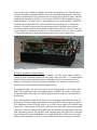
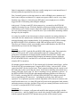
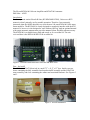
The Elecraft KXPA100 100 watt Amplifier and KXAT100 Autotuner
Phil Salas – AD5X
Introduction
Besides my main station Elecraft K-Line (K3/KPA500/KAT500), I also own a KX3
transceiver that I primarily use for portable operation. Therefore I was extremely
interested when the ARRL asked me to review the new 100-watt KXPA100 160-6 meter
linear amplifier. The KXPA100 is clearly designed to seamlessly interface with the KX3
transceiver, however is also designed to work with any QRP rig. And an optional internal
wide-range automatic antenna tuner provides antenna system flexibility when necessary.
The KXPA100 is available factory built and tested, or as a no-solder kit. The unit
reviewed here is the KXPA100/KXAT100 no-solder kit.
Figure 1: Elecraft KXPA100/KXAT100 Front and Rear views
First – the build!
The KXPA100/KXAT100 arrived in a small 7.5” x 11.5” x 13” box. Inside were two
boxes containing the fully assembled and tested main RF assembly and the KXAT100
tuner assembly, and a box containing the cabinet and associated hardware. See Figures 2
and 3.
Figure 2: KXPA100 arrives!
Figure 3: Kit sub-assemblies
Figure 4 shows the completed amplifier just before attaching the cover. The bottom two
pc board assemblies (amplifier and filter) come pre-mounted to the heatsink. Assembly
consists of mounting the UHF connectors and serial port jack to the back panel, and then
installing the front panel and full cover. If you have the KXAT100 autotuner (the top pc
board assembly), you simply remove four mounting screws on the amplifier, install four
standoffs, plug in the KXAT100, and re-install the four mounting screws on the tuner
assembly. Assembly requires only basic mechanical skills. Just follow the excellent
instruction manual (which is also available on the Elecraft web site), check off each step
as you complete it, and before you know it you’ll be finished! In my case, this was about
1.5 hours from the time I opened the main box until I was ready to apply power.
Figure 4: Ready for the cover
KXPA100 Amplifier Technical Details
The KXPA100 is powered directly from a standard +13.8VDC power supply capable of
at least 20-amps continuous current (24 amps peak). There is no fan – i.e. a large heatsink
provides the necessary thermal protection. A handle on the left side provides ease of
transport. And special rubber feet permit the amplifier to be mounted vertically (front
panel down) or in its normal horizontal upright position.
The amplifier outputs 100 watts from 160-6 meters with typically 5 watts of drive. PINdiode T/R switching provides silent QSK operation. And the T/R switch is specifically
designed to handle switching even with RF applied should a fault cause the amplifier to
be bypassed.
There is no amplifier bypass switch. However a relay bypasses the KXPA100 when it is
powered off, when the relay is commanded off by the KXPA Utility program, or when a
KX3 interfaced with a KXPACBL cable is set to 10W or less (or has its PA MODE menu
setting OFF). This eliminates PIN-diode switch loss (less than 1dB) when operating QRP
“barefoot”. However, with non-KX3 QRP radios the amplifier should be turned off when
QRP operation is desired. If a non-KX3 radio transmits when the KXPA100 is on but not
keyed, transmit RF passes through the receive path. While there will be no receive path
damage with transmit power up to 15 watts, the PIN-diode receive biasing is such that
significant out-of-spec harmonics will be generated. This was not clear in the Revision A
KXPA100 User Manual, and so we thought there was a problem with the amplifier. Our
KXPA100 was returned to Elecraft for analysis, which resulted in a manual revision for
clarification.
Our returned KXPA100 did benefit from two Elecraft hardware updates. The first was a
digital noise reduction improvement, and the second was the addition of diode isolation
of the T/R control line to prevent an external amplifier control line from back-feeding
into the KXPA100 internal switching. Any KXPA100 returned for any reason will
receive these updates at no charge.
The KXPA100 includes always-active frequency-sensed auto band-switching making
auto band-switching compatible with all transceivers. When a band change occurs
amplification is disabled, the correct low-pass-filter and input network is selected, time is
given for the relays to settle, and amplification is re-enabled. KX3 users can also take
advantage of auto band-switching without transmitting via the optional KXPACBL cable,
though frequency sensing always takes precedence.
The KXPA100 Display and Fault System
There is significant control, monitoring and display information available on the
KXPA100’s front panel. The bottom row of controls and indicators for SWR, mode,
antenna selection and ATU functions are present only if the optional KXAT100 antenna
tuning unit is installed.
DC power to the KXPA100/KXAT100 is controlled by the OFF/ON switch on the
amplifier, or by a KX3 if connected with the KXPACBL. LED Amplifier Status
Indicators show output power in watts, whether the rear panel input attenuator is switched
in or not, and if the amplifier is being keyed. Faults are displayed on the amplifier LEDs,
and on a KXPACBL-connected KX3 display. Faults include high SWR, excessive drive,
excessive output power, high current, and a system fault which requires a KX3 or the
KXPA Utility for more details. A fault condition suspends normal operation, normally by
bypassing the amplifier. The exception occurs when drive over 8-watts causes the 3dB
input attenuator to switch in. Faults clear automatically after a delay of about 8 seconds when
the condition causing it is corrected. After clearing, the fault message remains on the KX3 display
until any key is pressed.
Setting Up the Amplifier
Begin by installing 25-amp fuses in the supplied DC cable fuse holders if they are not
pre-installed. Then connect +13.8VDC and turn on the amplifier. Connect a PC via the
USB or RS232 interface and download and install the KXPA Utility. Update the
firmware to the latest version if necessary.
Connect a ground wire, RF IN/OUT and PA KEY cables to your transceiver. The PA
KEY interface is compatible with all transceivers. The optional KXPACBL cable
package provides the KX3 data interface and amp-keying connections.
Performance Measurements
Table 1 summarizes the measured amplifier performance.
Table 1: Elecraft KXPA100, serial number 0555
Manufacturer's Specifications
Measured in ARRL Lab
Frequency Range: All amateur frequencies in
160, 80, 40, 30, 20, 17, 15, 12, 10, 6 meters.
the range of 1.8 to 29.7 and 50-54 MHz.
Power supply and current: 12-15 V dc (13.8 V dc 19 A maximum, 17 A typical (HF). 11 A (50 MHz)
nominal), at 24 A peak capacity.
at 13.8 V dc.
Power output: 100 Watts, continuous HF, 80W
As specified; 88 W (HF), 65 W (50 MHz) at minimum
at 50 MHz.
specified operating voltage.
Driving power required: 5-7 Watts.
4-6 Watts (typical). See Table 2.
Input VSWR 1.5:1 or less
See Table 2.
Spurious and harmonic suppression: not specified. Typically 52 to 64 dB, except 44 dB at 1.8 MHz¹.
Meets FCC requirements.
Third order intermodulation distortion (IMD):
14 MHz, 3rd/5th/7th/9th: –32/–34/–42/–52 dB
36 dB below full power output.
below PEP (14 MHz); –31/–35/–40/–51 dB below
PEP (50 MHz).
Key In: Receive +5 Vdc open circuit,
As specified.
ground to transmit (1 mA maximum).
TR switching time: not specified.
Amplifier key to RF output: 3 ms; Amplifier
un-key to RF power off: 8 ms.
Size (HWD): 4.6 x 5.3 x 9.8 inches (including protrusions)
Weight, 5.3 lbs. (including ATU)
¹Second Harmonic. Harmonic is reduced as frequency increases on the 160 meter Amateur Band.
Other Specifications:
Duty Cycle at 100 W Output RTTY/Digital/FM, 60 seconds continuous carrier. 100 watts continuous
transmission on CW/SSB with a 50% duty cycle keying/modulation waveform. Thermally protected.
Efficiency ~50% at 100 watts output.
We did have a problem running our normal 2-tone tests in that the IMD performance was
poor. This did not occur when the driving transceiver was a KX3 with its amplifier
interface cables. Elecraft investigated this and determined that the wrong band was
sometimes being selected at low 2-tone power levels. The KXPA100 defaults to 6 meters
on power-up unless it is tracking an attached KX3. It then uses frequency sensing to
select the correct band for a non-KX3 driving transceiver. However, below about 0.5
watts the KXPA100 frequency counter becomes unreliable. So when a low-level 2-tone
signal is input the counter was getting confused, resulting in either no band change or a
change to the wrong band. In normal operation, even with SSB, low-level counter
operation was reliable. However, because of this particular issue Elecraft changed the
firmware to more reliably select the correct low-pass filter at very low power levels. The
new firmware should be production released by the time this review is published.
Table 2 details the measured amplifier input SWR and required drive for 100 watts output
(typically 4-6 watts of drive is required for full output). The KXPA100 bargraph display
and Utility power readings are pre-calibrated at the factory. The bargraph readings are
fairly coarse as power is indicated in 10-watt increments. I did find some discrepancies –
particularly on the higher bands - between the bargraph display and Utility readings when
compared to my NIST-traceable Minicircuits PWR-6GHS+ sensor and calibrated
attenuators.
TABLE 2: Serial Number 555 Amplifier Measurements: +13.9VDC Key-Down voltage,
Unkey 0.28amps, key down no drive 1.15 amps
Band
Drive Input SWR Pactual
Pbargraph
Putility
DC Current
160M 4.50W 1.52:1
100W
100W
99W
17.1A
80M
4.90W 1.49:1
100W
100W
98W
17.8A
40M
4.90W 1.44:1
100W
100W
97W
15.4A
30M
5.20W 1.33:1
100W
100W
97W
13.6A
20M
3.30W 1.56:1
100W
100W
96W
13.1A
17M
4.00W 1.53:1
100W
90W
95W
17.4A
15M
4.60W 1.35:1
100W
90W
94W
17.2A
12M
3.60W 1.29:1
100W
90W
92W
13.2A
10M
4.40W 1.40:1
100W
90W
92W
17.2A
*6M
3.20W 1.27:1
80W
70W
70W
12.5A
*The 6-meter output power specification is 80 watts. While this unit easily achieved 100watts on 6-meters (6.2 watts drive was required), power should be limited to 80 watts for
best IMD performance when using linear modes.
The Elecraft KXAT100 Automatic Antenna Tuner
Unless you have an almost perfect antenna system the optional internal KXAT100
antenna tuner is worth considering. Table 3 lists the KXAT100 specifications.
Table 3: KXAT00 Antenna Tuning Unit (ATU)
Frequency Range:
1.8 to 54 MHz, continuous.
Autotune Power:
3-watts minimum, 5-watts typical.
Tuner configuration: Series-L/Shunt-C, reversible-L matching network.
L/C Tuning Ranges: 8-capacitors (2624pf max) and 8-inductors (17370nHy max), relay
switched.
Matching Range: Up to 10:1 SWR at 100 watts; up to 20:1 SWR at 10 watts.
Antenna Interfaces: Two, rear panel. Manual and auto selectable.
ATU Memory segments: 10kHz wide below 3 MHz, 20 kHz wide from 3 MHz through
26 MHz, 100 kHz wide from 26 MHz to 38 MHz, and 200 kHz wide from 38 MHz to 60
MHz. The ATU also stores the antenna connector that you selected for each band.
KXAT100 Operation
The KXAT100 provides automatic or manual (user initiated) tuning – as well as bypass if
no tuning is required (bypass is a tuning solution if it results in a VSWR of <1.2:1
(default). In AUTO, tuning begins when the VSWR exceeds 1.8:1 (default). In MAN,
tuning is initiated when the TUNE button is pressed and 3-5 watts of RF carrier is
applied. However, even in the manual mode previously memorized tuner settings and
antenna selection information is automatically selected once the frequency is determined.
The KXAT100 modes (AUTO, MAN and BYP) are not remembered on a per-band basis
– i.e., when you select a specific mode, that mode will be used on all bands until you
change it.
The KXAT100 utilizes RF sensing (1st priority) or KX3 data to switch bands
automatically . The KXAT100 interrupts the KXPA100 during a band change, tune or
sudden high SWR condition.
The “start-tuning” VSWR threshold (1.8:1), and the bypass tuning solution (1.2:1) are
currently not changeable, but these values are quite appropriate for normal operation.
Figure 5 shows the KXPA Utility operating page.
Figure 5: KXPA Utility Operation Page
The KXAT100 two antenna switch ports can be memorized, along with tuning data, on a
per-band basis. Table 4 shows my measurements of the non-selected-to-selected port
isolation with an Array Solutions VNA2180. While this test is for a 50 ohm system,
actual antennas may result in much better isolation depending on the bands the antennas
are designed for, antenna directivity, and differences in antenna polarization. The
measured isolation does indicate that the KXAT100 antenna switch will be adequate for
most installations.
Table 4:
Band
20M
10M
6M
Antenna Port Isolation
ANT 2-1
48dB
43dB
40dB
Tuner Matching and Loss Measurements
Resistive matching range and loss testing was performed with the precision set-up
described in the August QST, 2012 antenna tuner review, p. 47 (see the QST-in-depth
section of that review for details). The test results are given in Table 5. Tuning power was
set at 5 watts per Elecraft recommendations. My NIST-traceable test equipment is spec’d
to +/-3% accuracy therefore all measured losses are subject to the +/-3% accuracy.
Table 5: KXAT100 Resistive load and loss testing
VSWR/Impedance
160m
80m
10:1/5Ω
Loss (%)
36
2
VSWR
2.8
1.18
8:1/6.25Ω Loss
27
0
VSWR
2.67
1.07
4:1/12.5Ω Loss
8
0
VSWR
1.71
1.12
3:1/16.7Ω Loss
8
0
VSWR
1.67
1.15
2:1/25Ω
Loss
6
0
VSWR
1.80 1.08
1:1/50Ω
Bypass Loss
0
0
Bypass VSWR 1.1
1.11
2:1/100Ω
Loss
0
0
VSWR
1.16
1.09
3:1/150Ω
Loss
0
0
VSWR
1.11
1.30
4:1/200Ω
Loss
6
0
VSWR
1.48
1.39
8:1/400Ω
Loss
5
1
VSWR
1.40
1.41
10:1/500Ω
Loss
4
0
VSWR
1.23
1.26
40m
6
1.26
0
1.07
0
1.22
0
1.34
20m
8
1.44
6
1.43
5
1.34
2
1.32
10m
10
1.08
8
1.17
6
1.21
4
1.12
6M
16
1.15
12
1.18
9
1.16
8
1.44
0
0
3
8
1.45
0
1.05
0
1.16
0
1.68
0
1.12
1
1.22
0
1.09
1.28
0
1.02
0
1.15
2
1.29
2
1.15
3
1.08
4
1.28
1.23
0
1.17
1
1.05
2
1.12
3
1.25
7
1.26
6
1.50
1.32
0
1.34
2
1.28
3
1.48
4
1.83
20
1.14
31
1.24
As you can see, the KXAT100 achieved its 1.8:1 or better VSWR target except for low
impedance 8:1 and 10:1 VSWR matching on 160 meters.
Open/Short Circuit Testing
Most (if not all) wide-range antenna tuners – both manual and automatic – can find a
match on one or more frequencies when connected to an open or a short. This is due to
finite-Q components, resulting in the tuner actually tuning into its own internal losses. I
did not perform the open/short test for two reasons.
First, I normally protect my driving transceiver with a 6dB high power attenuator as I
don’t want to subject my transceiver’s output to an open or short, even for a very short
duration event. However, when using my KX3 there is not enough power to reliably
trigger the KXAT100 tuning when using the 6dB pad.
And second – If using a non-KX3 driving transceiver, you must key the KXPA100
amplifier for tuning to occur. While the amplifier self protects almost immediately after
which tuning occurs, I didn’t want to subject the output of the amplifier to a short or open
for even a small amount of time. It would be nice if you could enable autotuning without
having to key the amplifier.
As it may be possible to tune into an open or short, I memorize my tuning solutions on
each band leave the antenna tuner in manual mode. The antenna tuner still selects the
memorized tuning values in manual mode. So if something causes the SWR to change,
the KXPA100/KXAT100 will indicate a high SWR and bypass itself if necessary.
Therefore you’ll know to check your antenna system, rather than have the KXAT100
automatically try to tune into the changed load.
Operating
Because I have a KX3, I used the Elecraft KXPACBL interface cable. This permits the
ATU's TUNE switch, ANT switch, and amplifier and ATU settings, faults and
performance information to be displayed and controlled from the KX3. Further, KX3
band changing results in automatic band changing and antenna selection within the
KXAT100 and KXPA100. And the KX3 even switches on the KXPA100/KXAT100
when the KX3 is turned on.
My antenna system consists of a 43-foot vertical and a 4-element 6-meter beam – perfect
for the KXAT100 two antenna ports. Using the KXPA Utility, I selected ANT1 for the
vertical and ANT2 for the 6-meter beam. Then I memorized tuning for the vertical on all
HF bands (the 43-foot vertical has the remote 160/80 meter matching as described in my
January 2010 QST article, page 34). Once everything is set-up, operation is a breeze. as
the KXPA100/KXAT100 picks the right antenna and tuning solution as it follows my
KX3. Frankly. operating the KX3 with the KXPA100/KXAT100 is almost exactly the
same as operating my K3 transceiver – including the perfectly silent full break-in
operation. A very pleasant experience indeed! Operation will be almost as seamless with
non-Elecraft transceivers, as a short RF signal will result in the appropriate band, antenna
and tuning memory selection. And don’t forget, all your custom preferences can be saved
if you lose or corrupt the KXAT100’s memory.
Conclusion
The KXPA100 is a compact, well-protected amplifier that integrates perfectly with the
KX3 transceiver – and to a slightly lesser extent with virtually all other QRP transceivers.
And the optional internal KX3AT antenna tuner provides all the antenna system
flexibility most hams will ever need. The KXPA100 is reasonably priced as solid-state
amplifiers go, and the no-solder kit is quite easy to build. If you occasionally need to
boost your QRP signal by a couple of S-units, the KXPA100 is certainly worthy of your
consideration.
Bottom Line: The KXPA100 is a compact 100-watt amplifier that is designed to work
with any QRP transceiver. Silent QSK operation and an optional internal wide-range
auto-tuner add capabilities not found in most other QRP amplifiers.
Manufacturer: Elecraft, PO Box 69, Aptos, CA 95001-0069; tel 831-763-4211; fax 831763-4218; www.elecraft.com.
List Prices: KXPA100: $699.95. KXPA100-F: $749.95. KXAT100 $299.95.
KXAT100-F $349.95. KXPACBL Optional KX3-to-KPXA100 Cable $29.95.