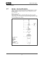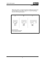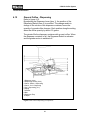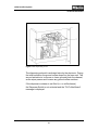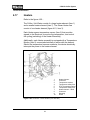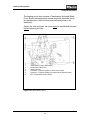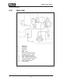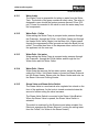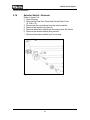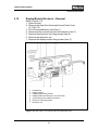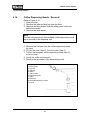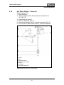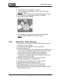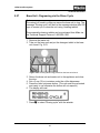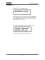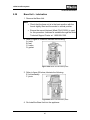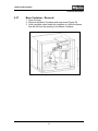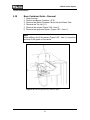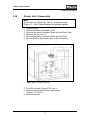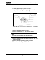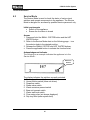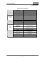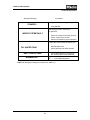
1
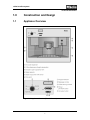
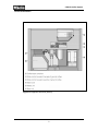
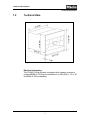
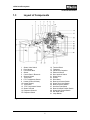
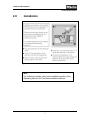
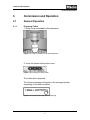
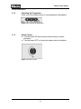
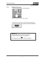
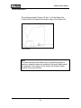
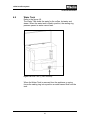
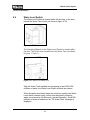
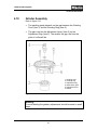
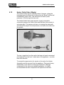
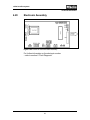
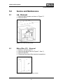
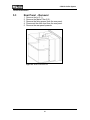
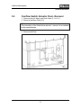
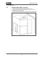
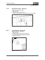
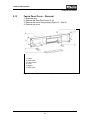
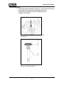
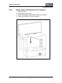
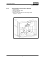
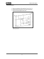
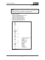
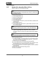
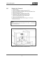
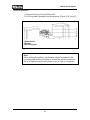
TECHNICAL INFORMATION
CVA610 Coffee System
© 2004 Miele
CVA610 Coffee System - Table of Contents
1.0 CONSTRUCTION & DESIGN
1.1 Appliance Overview
1
1.2 Technical Data
3
1.3 Layout of Components
5
2.0 INSTALLATION
Installation Procedures
7
3.0 COMMISSION and OPERATION
3.1 General Operation
9
3.1.1 Preparing Coffee
9
3.1.2 Canceling the Preparation
10
3.1.3 Steam Control
10
3.1.4 Hot Water Dispensing
11
3.1.5 Adjusting the Coffee Grinder
12
3.1.6 Filling the Coffee Bean Container
13
3.1.7 Filling the Water Tank
14
4.0 DESCRIPTION of FUNCTION
4.1 Door Switch
15
4.2 Overflow Switch
15
4.3 Brew Unit – Home Position
16
4.4 Brew Unit – Drive & Water Connections
17
4.5 Brewing Procedure
18
4.6 Waste Unit
21
4.7 Waste Unit Present Switch
21
4.8 Water Tank
23
4.9 Water Level Switch
24
4.10 Grinder Assembly
25
4.11Grinder – Overload Protection
26
4.12 Ground Coffee – Dispensing
28
4.13 Brew Unit Drives
30
4.14 Water Pump
32
4.15 Flow meter
33
4.16 Heater – Data
33
4.17 Heaters
34
4.0 DESCRIPTION of FUNCTION (Continued)
4.18 Water Path
36
4.18.1 Water Intake
37
4.18.2 Water Path - Coffee
37
4.18.3 Water Path – Hot Water
37
4.18.4 Water Path - Steam
37
4.18.5 Steam Valve and Steam Valve Switch
37
4.19 Heater Outlet Valve (Nipple)
38
4.20 Electronic Assembly
39
5.0 SERVICE and MAINTENANCE
5.1 Lid – Removal
41
5.2 Mains Filter – Removal
41
5.3 Rear Panel – Removal
42
5.4 Adjustment Slide Switch Frame - Removal
43
5.5 Door Contact Switch - Removal
44
5.6 Base Plate - Removal
45
5.7 Drip Tray - Removal
46
5.8 Overflow Switch Actuator Float - Removal
47
5.9 Overflow Switch - Removal
48
5.10 Fluorescent Lamp – Removal
49
5.11 Lamp Starter - Removal
49
5.12 Rear Door Panel – Removal
50
5.13 Fascia Panel Cover – Replacement
51
5.14 Selector Switch - Removal
52
5.15 Display Module Electronic – Removal
53
5.16 Coffee Dispensing Nozzle – Removal
54
5.17 Coffee Dispensing Nozzle - Fitting
55
5.18 Steam Valve and Steam Valve Switch - Removal
56
5.19 Hot Water Nozzle - Removal
57
5.20 Hot Water Nozzle - Removal
58
5.21 Coffee Temperature - Check
58
5.22 Brew Unit – Removal (in start/home position)
58
5.23 Brew Unit – Removal (NOT in start//home position)
59
5.24 Brew Unit – Installation
61
5.25 Brew Unit – Cleaning Procedure
61
5.0 SERVICE and MAINTENANCE (Continued)
5.26 Brew Unit – Filter Cleaning
62
5.27 Brew Unit – Degreasing via the Rinse Cycle
63
5.28 Brew Unit – Lubrication
65
5.29 Brew Unit – Manual Reset to “Home Position” (Brew Unit Not Installed)
66
5.30 Brew Unit Creamer Valve – Removal
67
5.31 Brew Unit Handle – Removal
67
5.32 Brew Unit Funnel – Removal
68
5.33 Brew Unit Ram – Service
69
5.34 Water Tank Level Indicator Float – Removal
71
5.35 Water Tank Sealing Ring – Removal
72
5.36 Lower Section of Tank Valve – Removal
73
5.37 Bean Container – Removal
75
5.38 Bean Container Guide – Removal
76
5.39 Grinder Unit – Disassembly
77
5.40 Grinder Unit – Assembly & Basic Setting
80
5.41 Grinder Unit – Removal
81
5.42 Brew Unit Present Switch – Removal
83
5.43 Dispensing Solenoid – Removal
83
5.44 Dispenser Switch – Removal
83
5.45 Brew Unit Drives – Home Positioning
84
5.46 Waterpath / Flowmeter Check
84
5.47 Waterpath Leakage Test
85
5.48 Water Connections – Releasing
86
5.49 Water Connections – Fitting
87
6.0 FAULT DIAGNOSIS
6.1 Programming Mode
89
6.2 Service Mode
90
6.3 Displayed Messages
92
6.4 Uneven Filling
94
6.5 Brew Unit – Can’t be removed from appliance
94
6.6 Brew Unit – Can’t be installed
94
6.7Grinder Setting – Can’t be set to finer position
95
CVA610 Coffee System – List of Figures
1-1 Appliance Overview (Exterior)
1
1-2 Appliance Overview (Interior)
2
1-3 Product Dimensions
3
1-4 Overview of Components
5
2-1 Installation Information
7
3-1 Coffee cup placed under both dispensers
9
3-2 Pressing the Coffee Button
9
3-3 Displayed Message During Dispensing
9
3-4 Canceling the preparation
10
3-5 Steam Control
10
3-6 Cup placed under hot water dispenser
11
3-7 Hot Water Button
11
3-8 Grinder Adjustment Control
12
3-9 Filling the Coffee Bean Container
13
4-1 Door Contact Switch
15
4-2 Brew Unit in home position
16
4-3 Brew Unit drive connections
17
4-4 Brew Unit Filters
18
4-5 Brew Unit Components
19
4-6 Brew Unit releasing a “puck”
20
4-7 Waste Unit Present Switch
21
4-8 Waste Unit Magnet
22
4-9 Water Tank Valve
23
4-10 Water Level Switch
24
4-11 Water Level Switch Float
24
4-12 Grinder Assembly
25
4-13 Grinder Overload Protection Components
26
4-14 Grinder Cone Ball Positions
27
4-15 Coffee Dispensing Components
28
4-16 Dispensing Lever
29
4-17 Brew Unit Drive Components
30
4-18 Brew Unit Drive Assembly
31
4-19 Water Pump
32
4-20 Hot Water / Coffee Heater
34
4-21 Steam Heater
35
4-22 Water Path
36
4-23 Heater Drainage Nipple
38
CVA610 Coffee System – List of Figures (Continued)
4-24 Electronic Board (Layout)
39
5-1 Lid and Securing Screws
41
5-2 Mains Filter Mounting
41
5-3 Rear Panel – Removal
42
5-4 Removing the Slide Switch Frame
43
5-5 Door Switch
44
5-6 Base Plate Removal
45
5-7 Drip Tray
46
5-8 Overflow Switch Float
47
5-9 Overflow Switch
48
5-10 Fluorescent Lamp Access and Removal
49
5-11 Starter Removal
49
5-12 Rear Door Panel – Removal
50
5-13 Fascia Panel Cover Assembly
51
5-14 Selector Switch
52
5-15 Rear View of Front Door w/ Panel Removed
53
5-16 Coffee Dispensing Components
54
5-17 Steam Valve and Steam Valve Switch
56
5-18 Hot Water Valve
57
5-19 Brew Unit Connection Socket
60
5-20 Brew Unit Connection Socket Retaining
60
5-21 Brew Unit Removal
61
5-22 Brew Unit Installation
62
5-23 Cleaning Tablet being placed into brew unit
63
5-24 Brew Unit – lubrication points (1)
65
5-25 Brew Unit – lubrication points (2)
65
5-26 Moving the Brew Unit to the home position
66
5-27 Brew Unit in reset position
66
5-28 Brew Unit (output and retaining lugs)
67
5-29 Rear of Brew Unit
68
5-30 Front of Brew Unit
68
5-31 Brew Unit Ram
69
5-32 Brew Unit Chamber
70
5-33 Brew Unit Ram and Filter Removed
70
5-34 Removing cap to tank float
71
5-35 Levering off the Lip Seal Cap
72
5-36 Removing the Lip Seal
72
5-37 Water Tank Lip Seal – Removal
73
CVA610 Coffee System – List of Figures (Continued)
5-38 Underside view of the CVA610
74
5-39 Removing the Bean Container
75
5-40 Removing the Beans Container Guide
76
5-41 Accessing the Grinder
77
5-42 Upper section of the Grinder
78
5-43 Grinder
79
5-44 Grinder Removal
81
5-45 Grinder Coupling
82
5-46 Brew Unit Present Switch
83
5-47 Water System Connection
86
CVA610 Coffee System – List of Tables
5-1 Programming Mode
89
5-2 Service Mode Navigation
91
5-3 Displayed Messages (part 1 of 2)
92
5-4 Displayed Messages (part 2 of 2)
93
CVA610 Coffee System
Technical Information
1.0
Construction and Design
1.1
Appliance Overview
Figure 1-1: Appliance Overview (Front & Controls)
1
CVA610 Coffee System
Technical Information
Figure 1-2: Appliance Overview (Interior)
2
CVA610 Coffee System
Technical Information
1.2
Technical Data
Figure 1-3: CVA610 Product Dimensions
Electrical Information
The CVA610 Coffee System is equipped with a power cord and a
molded NEMA 6-15P plug for connection to a 240 (208) V, 15 A, 60
Hz NEMA 6-15R (receptacle).
3
CVA610 Coffee System
Technical Information
4
CVA610 Coffee System
Technical Information
1.3
Layout of Components
1
2
3
4
5
6
7
8
9
10
11
12
13
14
Steam Valve Switch
Door Magnet
Fluorescent Bulb
Starter
Control Panel / Electronic
Selector Switch
Thermostat
PTC Temperature Sensor
Heater (Coffee & Water)
Heater (Steam)
Thermostat
PTC Temperature Sensor
Steam Solenoid
Dispenser Solenoid
15 Dispenser Switch
16
17
18
19
20
21
22
23
24
25
26
27
28
29
30
31
Figure 1-4: Overview of Components
5
Terminal Block
Flowmeter
Interference Capacitor
Electronic Board
Door Interlock Switch
Water Pump
Grinder
Drive Motor
Brew Unit Present Switch
Water Tank Level Switch
Brew Unit Home Switch
Overflow Float Switch
Brew Unit Brew Position Switch
Waste Unit Present Switch
Hot Water Valve
Lamp Ballast
CVA610 Coffee System
Technical Information
6
CVA610 Coffee System
Technical Information
2.0
Installation
Figure 2-1: Installation Information
Note
For further information, refer to the installation section of the
Operating Manual -OR- the Miele installation Manual.
7
CVA610 Coffee System
Technical Information
8
CVA610 Coffee System
Technical Information
3.
Commission and Operation
3.1
General Operation
3.1.1
Preparing Coffee
1. Place a cup under both coffee dispensers.
Figure 3-1: Coffee cup placed under both dispensers.
2. Press the desired coffee button once.
Figure 3-2: Pressing the coffee button
The coffee will be prepared.
The following message will appear in the message window,
depending on the button pressed:
Figure 3-3: Displayed Message While Dispensing
9
CVA610 Coffee System
Technical Information
3.1.2
Canceling the Preparation
Press one of the coffee buttons to stop preparation immediately.
Figure 3-4: Canceling the preparation
3.1.3
Steam Control
● Turn the steam ON by turning the steam selector counterclockwise.
● Turn the steam OFF by turning the steam selector clockwise.
Figure 3-5: Steam Control
10
CVA610 Coffee System
Technical Information
3.1.4
Hot Water Dispensing
1. Place a cup under the hot water dispenser.
Figure 3-6: Cup placed under hot water dispenser
2. Press the hot water button. Hot water will be dispensed.
3. Press the hot water button again to stop the hot water flow.
Figure 3-7: Hot water button
Service Tip
The hot water dispensing stops automatically if…
a specific volume (cup size) is programmed
and
the "Programmed Hot Water" feature is activated.
11
CVA610 Coffee System
Technical Information
3.1.5
Adjusting the Coffee Grinder
Controls:
to the left for finer grinding
to the right for coarser grinding.
Figure 3-8 Grinder Adjustment Controls
If the coffee flows too quickly, the beans have been ground too
coarsely. Adjust the grinder to a finer setting.
If the coffee trickles, the beans have been ground too finer.
Adjust the grinder to a coarser setting.
Note
You should be able to feel the notches when moving the slide
control.
If the slide control will not move:
Close the machine and dispense a cup of coffee. Then try to
move the slide control again.
12
CVA610 Coffee System
Technical Information
3.1.6
Filling the Coffee Bean Container
1. Carefully pull the container outward until the lid is visible.
2. Lift the lid (as shown in figure 3-9.
3. Fill the container with coffee beans to about 1" from the top.
4. Close the lid and push the container back into place.
5. Shut the appliance door.
Figure 3-9 Filling the Coffee Bean Container
Important
Only put pure espresso or coffee bean in the container. Anything
else, including ground coffee, hot cocoa, instant coffee, or treated
coffee beans (flavorings, caramel, or sugar) will damage the
grinder.
Service Tip
Always remove all coffee beans before attempting to remove the
bean container. Failure to do so will result in the beans spilling out!
Refer to 5.37 for additional information.
13
CVA610 Coffee System
Technical Information
3.1.7
Filling the Water Tank
The Water Tank must be cleaned and filled with fresh water before
each day of use. A reminder will appear in the message
window when the unit is first turned on.
1. Open the front of the machine.
2. Lift the water tank up and out of the appliance.
3. Open the lid and fill the container with cold drinking water to
within about 1" (2 cm) of the top.
Important
Never add hot water or any other liquids to the water tank.
4. Close the lid and place the tank in the machine, pushing it
straight back. Ensure the tank is fully seated into position.
14
CVA610 Coffee System
Technical Information
4.0
Description of Function
4.1
Door Switch (S24)
The Door Switch interrupts the main power circuit when the door is
opened.
Figure 4-1: Door Contact Switch (S24)
4.2
Overflow Switch (B8/3)
The Overflow Switch is mounted to the bottom of the casing. The
associated float (with internal magnet) is located within the drip
tray. Should a leak develop, water flows into the drip tray. The float
rises and the Overflow Switch becomes actuated. The electronic
then displays the “Watersystem Fault” message.
15
CVA610 Coffee System
Technical Information
4.3
Brew Unit – Home Position
Refer to figure 4-2. The brew unit must be in the “home position”
before it can be removed from the appliance.
Fig. 4-2: Brew Unit in the “home” position
16
CVA610 Coffee System
Technical Information
4.4
Brew Unit – Drive and Water Connections
Refer to figure 4-3.
When the Brew Unit is installed, it locks into position. The Locking
Mechanism Switch Lug (item 3), activates the Brew Unit Present
Switch (item 4). The Drive Shaft (item 6), engages with the Drive
Shaft Socket (item 1) to provide drive to the Brew Unit.
When the Brew Unit moves into the “Brewing Position” the Hot
Water / Water Connection Socket (item 2) connects to the Nozzle
on the Hot Water / Coffee Heater (item 5).
1 Drive Shaft Socket
2 Water Connection Socket
3 Locking Mechanism Switch Lug
4 Brew Unit Present Switch
5 Water Nozzle
6 Drive shaft
Figure 4-3: Brew Unit drive connections
17
CVA610 Coffee System
Technical Information
4.5
Brewing Procedure
1. The output of the Grinder provides ground coffee to the
Dispenser Housing; until it filled (as determined by the
dispenser switch).
2. The Grinder is then powered by off by the Electronic.
3. The Dispenser Flap opens twice (two clicks can be heard) via
the Dispenser Solenoid.
4. The ground coffee falls into the Brew Unit (via the funnel).
1 Funnel
2 Percolator chamber
3 Bottom filter
Figure 4-4: Brew Unit Filters
18
CVA610 Coffee System
Technical Information
Refer to figure 4-5
5. The Brew Unit Drives move the Brew Unit into the “Brewing
Position” (as determined by the Brew Position Switch). The
grounds are compressed between the top filter (item 2) and
bottom filter (item 5).
6. The Water Pump is energized to pump the water through the
Hot Water / Coffee Nozzle and into the Brew Unit via the Water
Connection Socket (item 4). The hot water forces through the
brew unit and the compressed grounds (Pos 3) and exits the top
of brew unit via the drain spout (item 1).
With the door of the appliance closed, the drain spout makes
contact with the dispensing system on the front of the appliance.
The users cup is filled with coffee, as the coffee flow exits.
1 Percolator Outlet
2 Top Filter
3 Compressed Coffee
4 Water Connection Socket
5 Bottom Filter
Figure 4-5: Brew Unit components.
19
CVA610 Coffee System
Technical Information
Refer to figure 4-6…
7. The drives are energized (in reverse) and move the Brew Unit
toward the “home position” position. As this action occurs the
coffee chamber moves upward and releases the used
compressed coffee grounds. (item1).
8. The drives continue, returning the Brew Unit to the “home
position” (as determined by the Home Position Switch.
Figure 4-6: Brew Unit, showing compressed coffee “puck”.
20
CVA610 Coffee System
Technical Information
4.6
Waste Unit
After coffee has been prepared, the compressed coffee grounds
“puck” falls into the Waste Unit. The electronic monitors the number
of the compressed “pucks”, until a specific value is reached. The
electronic then displays the “Empty Waste Unit” message to the
user.
4.7
Waste Unit Present Switch
The Waste Unit Present Switch is mounted to the bottom of the
CVA610 housing (behind the area of the Waste Unit) – as shown in
the figure 4-7.
Figure 4-7: Waste Unit Present Switch.
21
CVA610 Coffee System
Technical Information
The actuating magnet (Figure 4-8, item 1) for the Waste Unit
Present Switch is located at the bottom edge of the Waste Unit.
Figure 4-8: Waste Unit. (1) Magnet for Waste Unit
Present Switch.
Note
On newer manufactured Waste Units, an additional magnet is
present to keep the waste unit attached to the metal frame inside
the appliance. The magnet for the Waste Unit Present Switch
remains in the same location.
22
CVA610 Coffee System
Technical Information
4.8
Water Tank
Refer to the figure 4-9.
The Water Tank holds the water for the coffee, hot water and
steam. When the water tank is fitted in position, the sealing ring
presses upward so water cannot leak.
Figure 4-9: Water Tank (1) Valve Assembly.
When the Water Tank is removed from the appliance; a spring
forces the sealing ring into a position so water cannot flow from the
tank.
23
CVA610 Coffee System
Technical Information
4.9
Water Level Switch
The Water Level Switch is located within the housing, in the area
behind the Water Tank Cavity (as shown in figure 4-10).
Figure 4-10: Water Level Switch
The Actuating Magnet for the Water Level Switch is located within
the float. The float is then installed into the Water Tank (as shown
in figure 11, item 1).
Figure 4-11: Water Level Switch Float
With the Water Tank installed and containing at least 900-1000
milliliters of water, the Water Level Switch contacts are closed.
When the water level drops below the minimum quantity, the Water
Level Switch contacts open. At this time the quantity incoming
water is monitored by the Electronic (via the flowmeter). Once 800
milliliters of water is measured, the “Fill Water Tank” message is
displayed.
24
CVA610 Coffee System
Technical Information
4.10
Grinder Assembly
Refer to figure 4-12.
The grinding grade depends on the gap between the Grinding
Cone (Item 1) and the Grinding Ring (Item 2).
The gap is set via the Adjustment Lever, (Item 5) on the
Adjustment Ring (Item 3). The smaller the gap, the finer the
grind of coffee will be.
1 Grinding cone
2 Grinding ring
3 Adjustment ring
4 Intake worm gear
5 Adjustment lever
6 Handle
Figure 4-12: Grinder Assembly
Warning!
To avoid binding the grinder, adjustments should be made in small
steps.
25
CVA610 Coffee System
Technical Information
4.11
Grinder - Overload Protection
Should the grinder become blocked by a foreign object (i.e. stone /
pebble), the slip coupling interrupts the drive between the motor
and the grinder.
Refer to figure 4-13…
The Grinder Motor (item 1) drives the Mounting (item 3) via the
Carriers (item 2). This rotary force transfers through the Balls, (item
5) to the Grinder Cone (Item 6).
1 Grinder motor
2 Carrier
3 Mounting
4 Spring
5 Ball
6 Grinding cone
7 Washer
8 Intake worm gear
Figure 4-13: Components of the Grinder Overload Protection
26
CVA610 Coffee System
Technical Information
Should the grinder cone become blocked, the Balls get pressed into
the Mounting (as shown below in figure 4-14, Item C) resulting in
the drive force being interrupted.
A Normal operation
B Overload protection activated
C Force transfer interrupted
Figure 4-14: Grinder cone ball positions under various operating conditions.
27
CVA610 Coffee System
Technical Information
4.12
Ground Coffee - Dispensing
Refer to figure 4-15.
By adjusting the Dispenser Lever (item 1), the position of the
Dispensing Switch (item 2) is modified. The change results in
change to the volume of the dispenser container; hence the
quantity of ground coffee changes. Each position along the setting
alters the coffee quantity by about 0.5 grams.
The grinder fills the dispenser container with ground coffee. When
the dispenser container is full, the Dispenser Switch is activates
and the grinder motor is switched off.
1 Dispenser Lever
2 Dispensing Switch (1S13)
3 Catch - Switch - Dispensing
4 Catch - Coil - Dispensing
5 Coil - Dispensing (1L1)
6 Spring
7 Actuator
8 Bolt
9 Dispenser Flap
10 Wiper
Figure 4-15: Coffee Dispensing Components
28
CVA610 Coffee System
Technical Information
Figure 4-16: Dispensing Lever
The dispensing solenoid is activated twice by the electronic. During
the initial activation the ground coffee drops into the brew unit. The
second activation is to ensure no loose grounds block the channel,
as the wiper passes and loosens any ground coffee residues.
If the dispenser container is not filled (i.e. no coffee beans)
the Dispenser Switch is not activated and the “Fill Coffee Beans”
message is displayed.
29
CVA610 Coffee System
Technical Information
4.13
Brew Unit Drives
Refer to figure 4-17…
The Brew Unit locks into position against the Drives Mounting
Plate. The locking mechanism Switch Lug (Item 3) activates the
Brew Unit Present Switch (Item 4). The Drive Shaft, (Item 6)
engages with the Percolator Drive Shaft Socket,
1 Drive Shaft Socket
2 Socket
3 Locking Mechanism & Switch Lug
4 Brew Unit Present Switch
5 Coffee / Hot Water Heater Nozzle
6 Drive Shaft
Figure 4-17: Components of the Brew Unit Drive Assembly.
30
CVA610 Coffee System
Technical Information
Refer to figure 5-18.
The Drive Motor (Item 4) powers the Worm Gear (Item 3). The drive
action is transferred to the Step-down Gear and then the Drive
Gear. The center of the Drive Gear contains the Drive Shaft that
connects to the Brew Unit Drive Shaft Socket. The drive gear The
drive shaft cog wheel has two switch actuators, (Items 2 & 5) for the
limit switches for the brew position and home position. The
electronic unit registers the brew position and the home position via
the limit switches, (Items 1 and 7).
1
2
3
4
5
6
7
Switch – home position switch
Switch actuator – home position
Bearing bush
Brew unit drive motor
Switch actuator – brew position
Fitting marking
Switch – brew position
Figure 4-18: Brew Unit Drive Assembly
31
CVA610 Coffee System
Technical Information
4.14
Water Pump
The pump is self-priming and can develop a pressure of up to
approx. 16 bar. For espresso preparation a pressure of approx. 8
bar is required so that the water can be forced through the
compressed ground coffee. A further increase in pressure does not
improve beverage quality.
The pump is fitted with a safety valve which opens at 16 bar system
pressure. If pressure is too high, water is passed from the safety
valve via a hose to the fitting plate and from there to the housing
under the percolator unit. The water is then passed through the
door rear panel to the drip tray.
The pump is connected in series with a temperature limiter. The
temperature limiter switches off the pump if a high temperature is
developed.
Figure 4-19: Water Pump
32
CVA610 Coffee System
Technical Information
4.15
Flow meter
All water taken from the water container flows through the flow
meter. The flow meter passes signals to the electronic unit
proportional to the quantity of water passing through it.
The electronic unit then establishes the quantity of water that has
flowed and stores the figure. Approx. 300 pulses from the flow
meter indicate a flow of 100 ml water.
The electronic unit controls the required water quantity for beverage
preparation and ensures that it remains constant. The service mode
can be used to check the proper operation of the flow meter.
4.16
Heater - Data
Coffee / Hot Water Heater 1R1 & 1R2
Voltage 220(240) V
Power rating 1090 W / 437 W
Steam Heater 2R1
Voltage 220(240) V
Power rating 1100 W
33
CVA610 Coffee System
Technical Information
4.17
Heaters
Refer to the figure 4-20…
The Coffee / Hot Water consist of a large heater element (Item 1)
and a smaller heater element (item 7). The Steam Heater has
consist of one heater element (figure 4-21, Item 3).
Each Heater uses a temperature sensor (Item 5) that provides
signals to the Electronic to monitor the temperature ; and control
the cycling (switching) of the Heater Element(s).
Additionally, each Heater assembly is equipped with a Temperature
Monitor (Item 3) connected electrically in series with the element.
Should the temperature become excessive, the device electrically
interrupts the power to the heater element.
1
2
3
4
5
6
7
8
9
10
Heater element
Connector
Temperature monitor
Temperature safety fuse
PTC Temperature sensor
Temperature safety fuse
Heater element - Small
Connector
Mounting
Outlet
Figure 4-20: Hot Water / Coffee Heater (1R1 and 1R2)
34
CVA610 Coffee System
Technical Information
The heating circuit also contains a Temperature Activated Safety
Fuse. Should the temperature exceed a specific threshold due to
an operating fault, the fuse blows and interrupts power to the
element(s).
Should this fuse be blown, the cause must be located and resolved
before replacing the fuse.
1
2
3
4
5
6
Temperature monitor (thermostat)
Temperature safety fuse
Heater element
Connector - Pressure system to steam valve in door
Connector - Pressure system from steam valve (solenoid valve)
PTC Temperature sensor (2R30)
Figure 4-21: Steam Heater (2R1)
35
CVA610 Coffee System
Technical Information
4.18
Water Path
1
2
3
4
5
6
7
8
9
10
11
12
13
14
Water tank
Sealing ring
Water filter
Flow meter
Pump
Valve - Safety
Drain hose - Excess pressure
Through-flow heater - Coffee
Outlet to brew unit (nipple)
Valve - Steam (solenoid valve)
Valve - Hot water (solenoid valve)
Through-flow heater - Steam
Valve - Steam (in door)
Frothing nozzle
Figure 4-22: Water Path
36
CVA610 Coffee System
Technical Information
4.18.1
Water Intake
The Water Pump is responsible for taking in water from the Water
Tank. The bottom of the pump contains a safety valve. The valve is
designed to open should the system pressure exceed 16 bar (232
psi). A hose is connected to the valve to route the water away from
the components.
4.18.2
Water Path - Coffee
Water exiting the Water Pump is pumped under pressure through
the Flowmeter, through the Coffee / Hot Water Heater and through
the Heater Outlet Valve (Nipple) into the Brew Unit. Water passes
through the compressed coffee grounds and exits the Brew Unit as
coffee. The coffee then flows to the dispenser tubes on the front of
the appliance into the user cup.
4.18.3
Water Path - Hot water
Water exiting the Water Pump is pumped under pressure through
the Flowmeter, through the Coffee Heater and through the Hot
Water Valve and Hot Water Outlet.
4.18.4
Water Path - Steam
Water flows the same as the hot water system, except the water
exiting the Coffee / Hot Water Heater is routed via Steam Solenoid
into the Steam Heater. Steam exits the Steam Heater and exits via
the Steam Valve and Frothing Nozzle.
4.18.5
Steam Valve and Steam Valve Switch
The Steam Valve is a mechanical valve regulated via a knob on the
front of the appliance. As the knob is turned counterclockwise the
amount of steam exiting the valve increases.
The Steam Valve Switch is mounted to the Steam Valve Bracket.
When the Steam Valve is opened, the Steam Valve Switch is
actuated.
The switch is monitored by the Electronic and when actuated, the
Electronic energizes the Steam Solenoid (routing the exiting water
from the Coffee / Hot Water to the Steam Heater).
37
CVA610 Coffee System
Technical Information
4.19
Heater Outlet Valve (Nipple)
The Heater Outlet Valve is normally closed. However, during the
brewing process the Brew Unit is driven into the “Brew Position and
mechanically opens valve. This allows the hot water (under
pressure) to flow through the brew unit.
The Heater Outlet Valve uses several o-rings to ensure the
connection between the Outlet Valve and the Brew Unit remain air
and water tight. This ensures air does not entering the water path
and disrupt the proper flow and pressure; and water does leak from
the system.
Figure 4-23: Heater Drainage (Nipple)
The two o-rings that form the seal to the brew unit can be accessed
and replaced from the front / inside area of the appliance - once the
brew unit removed.
To access the upper seal or for service on the valve; the Heater
Assembly must be removed from the appliance. This permits easy
disassembly of the valve for a thorough inspection. Although
components of the valve are available separately, it is highly
recommended the three components be replaced at one time.
38
CVA610 Coffee System
Technical Information
4.20
Electronic Assembly
Figure 4-24: Preview of Electronic Board Assembly
For further information on the electronic modes
– refer to section 6 “Fault Diagnosis”
39
CVA610 Coffee System
Technical Information
40
CVA610 Coffee System
Technical Information
5.0
Service and Maintenance
5.1
Lid - Removal
1. Remove the lid screws, as shown in Figure 5-1
2. Remove the lid.
Figure 5-1: Lid and securing screws
5.2
Mains Filter (Z1) - Removal
1.
2.
3.
4.
Perform: Lid removal (5.1).
Remove the mains filter nut (Figure 2 - Item 1).
Remove the Filter.
Disconnect the mains filter electrical connections
Figure 5-2: Mains Filter (Z1) Mounting Location
41
CVA610 Coffee System
Technical Information
5.3
Rear Panel - Removal
1.
2.
3.
4.
5.
Remove the lid (5.1).
Remove the Mains Filter (5.2).
Remove the fixing screws from the rear panel.
Disconnect the earth lead from the rear panel.
Remove the rear panel upwards.
Figure 5-3: Rear Panel Removal
42
CVA610 Coffee System
Technical Information
5.4
Adjustment Slide Switch Frame - Removal
1. Open the door.
2. Pull off the slide switch knobs.
3. Press the retaining lugs inwards with a small screwdriver
(Figure 5-4).
4. Remove the frame.
Figure 5-4: Removing the Adjustment Slide Switch Frame (Bezel).
43
CVA610 Coffee System
Technical Information
5.5
Door Contact Switch (S24) - Removal
Refer to figure 5-5 below…
1.
2.
3.
4.
5.
Remove the lid (5.1)
Open the door.
Disconnect the door switch connections.
Press the switch retaining lugs inwards with a small screwdriver.
Remove the door switch to the front.
Figure 5-5: Door Switch (shown with appliance door in open position)
44
CVA610 Coffee System
Technical Information
5.6
Base Plate - Removal
1.
2.
3.
4.
5.
Remove the Lid, Mains and Rear Panel (5.1 to 5.3)
Open the door.
Remove the grounds container.
Remove the water tank.
Check if water is present in the drip tray with a finger through
the opening under the water container.
6. If water is present, remove it via a suitable device / tool.
7. Remove the percolator unit.
8. Remove the coffee beans from their container.
9. Remove the base plate fixing screws.
10. Tilt the unit onto its rear.
11. Remove the base plate and disconnect its earth lead.
Figure 5-6: Base Plate – Removal
45
CVA610 Coffee System
Technical Information
5.7
Drip Tray - Removal
1. Remove the Lid, Mains and Rear Panel (5.1 to 5.3)
2. Remove the Base Plate (5.6)
3. Remove the drip tray.
Figure 5-7: Drip Tray
46
CVA610 Coffee System
Technical Information
5.8
Overflow Switch Actuator Float - Removal
1. Remove the Lid, Mains and Rear Panel (5.1 to 5.3)
2. Remove the Base Plate (5.6)
Note
The orientation of the float before removal – ensure it is re-installed
in the same direction.
3. Remove the Float.
Figure 5-8: Overflow Switch Float
47
CVA610 Coffee System
Technical Information
5.9
Overflow Switch (B8/3) - Removal
1.
2.
3.
4.
Remove the Lid, Mains and Rear Panel (5.1 to 5.3)
Remove the overflow switch fixing screw (Figure 9 – Item 1).
Remove the overflow switch.
Disconnect the overflow switch connections from the electronic.
Figure 5-9: Overflow Switch
48
CVA610 Coffee System
Technical Information
5.10
Fluorescent Lamp - Removal
Refer to the figure 5-10 below…
1. Open the door.
2. Unclip the cover and remove it.
3. Turn the lamp tube 90° in the direction to remove the lamp.
Figure 5-10: Fluorescent Lamp Access and Removal.
5.11
Lamp Starter - Removal
Refer to the figure 5-11 below…
1. Open the door.
2. Unclip the neon tube cover and remove it.
3. Turn the starter in the direction of the arrow.
4. Remove the starter.
Figure 5-11: Starter Removal
49
CVA610 Coffee System
Technical Information
5.12
Rear Door Panel - Removal
Refer to figure 5-12.
1. Open the door.
2. Remove the upper rear panel fixing screws (Item 1).
3. Remove the lower rear panel fixing screws (Item 2).
Figure 5-12: Rear Door Panel – Removal.
50
CVA610 Coffee System
Technical Information
5.13
Fascia Panel Cover – Removal
1. Open the door.
2. Remove the Rear Door Panel (5.12).
3. Remove the cover fixing screws (Figure 12 – Item 3).
4. Remove the cover.
1 Fascia
2 Cable guide
3 Fixing screws
4 Cover
5 Magnet
6 Cable guide
Figure 5-13: Fascia Panel Cover Assembly
51
CVA610 Coffee System
Technical Information
5.14
Selector Switch - Removal
Refer to figure 5-14.
1. Open the door.
2. Remove the Rear Door Panel and Fascia Panel Cover
(5.12 & 5.13).
3. Disconnect the connections from the selector switch,
4. Remove the switch knob (Item 9).
5. Remove the selector switch with its housing from the fascia.
6. Remove the selector switch fixing screws.
7. Remove the selector switch from its housing.
Figure 5-14: Selector Switch
52
CVA610 Coffee System
Technical Information
5.15
Display Module Electronic - Removal
Refer to figure 5-15.
1. Open the door.
2. Remove the Rear Door Panel and Fascia Panel Cover
(5.12 & 5.13).
3. Pull off the pushbutton knobs (Item 1).
4. Disconnect the connections from the electronic (Item 7).
5. Remove the electronic unit fixing screws (Item 6).
6. Remove the electronic unit.
7. Remove the display module fixing screws (Item 3).
1
2
3
4
5
6
7
Pushbuttons
Display module,
Display module fixing screws
Display module and electronic unit connection
Control and power modules connection
Electronic unit fixing screws
Electronic unit
Figure 5-15: Rear View of Front Door with Rear Panel Removed.
53
CVA610 Coffee System
Technical Information
5.16
Coffee Dispensing Nozzle - Removal
Refer to Figure 5-16.
1. Open the door.
2. Remove the grille and drip tray from the door.
3. Remove the fixing screws from the white panel under and
behind the nozzle.
4. Remove the white panel.
Note
The two fixing screws for the moveable coffee-dispensing nozzle
are on the rear of the dispenser unit.
5. Remove the 2 screws from the coffee-dispensing nozzle
by hand.
6. Pull out the hose (Item 6), from the outlet, (Item 7).
7. Pull out the moveable coffee dispensing nozzle (Item 9),
to its end stop.
8. Unclip the outlet and remove it.
9. Remove the moveable coffee dispensing nozzle.
1 Fixing screw
2 Drip tray
3 Underlay
4 Outlet
5 Cable holder
6 Connection hose
7 Outlet
8 Retainers
9 Moveable dispensing nozzle
10 Cover
Figure 5-16: Components of the Coffee Dispensing Nozzle.
54
CVA610 Coffee System
Technical Information
5.17
Coffee Dispensing Nozzle - Fitting
Refer to figure 5-16.
1. Slide the outlet (Item 7), onto the connection hose (Item 6).
2. Position the moveable coffee dispensing nozzle, (Item 9), in the
cover (Item 10).
3. Clip the outlet (Item 7), in the cover (Item 10).
Note
The two fixing screws for the coffee dispensing nozzle should be
tightened by hand only as they can easily be over tightened.
4. Fit the Coffee Dispensing Nozzle in the frame. Using a suitable
bit, tighten the two fixing screws by hand.
5. Refit the white panel and screw it in position.
55
CVA610 Coffee System
Technical Information
5.18
Steam Valve and Steam Valve Switch (S79) – Removal
Refer to Figure 5-17.
1. Open the door.
2. Remove the Rear Door Panel and Fascia Panel Cover
(5.12 & 5.13).
3. Pull off the switch knob (Item 8).
4. Remove the holder fixing screws (Item 3).
5. Remove the holder.
6. Remove the steam generator switch screws (Item 10).
7. Remove the steam generator switch.
8. Disconnect the steam generator switch connections.
1 Switch - Steam generator (S79)
2 Underlay
3 Fixing screws - Holder
4 Fixing screws - Valve housing
5 Holder
6 Valve housing - Steam
7 Valve insert - Steam
8 Switch knob
9 Switch feeler
10 Fixing screw - Switch
Figure 5-17: Components of Steam Valve and Steam Valve Switch
56
CVA610 Coffee System
Technical Information
5.19
Hot Water Nozzle – Removal
Refer to figure 5-18.
1. Open the door.
2. Remove the Rear Door Panel and Fascia Panel Cover
(5.12 & 5.13).
3. Loosen the nut (Item 2).
4. Remove the holder (Item 5).
5. Unscrew the sleeve, (Item 1) from the connector (Fig. 6).
6. Pull out the hot water nozzle (Item 3), from the connector.
1 Sleeve
2 Nut
3 Hot water nozzle
4 Fixing screws - Holder
5 Holder
6 Connector
7 Hot water valve (Y12)
Figure 5-18: Hot Water Valve Components
57
CVA610 Coffee System
Technical Information
5.20
Hot Water Valve (Y12) – Removal
Refer to figure 5-18.
1. Open the door.
2. Remove the Rear Door Panel and Fascia Panel Cover
(5.12 & 5.13).
3. Disconnect the connections from the hot water valve (Item 7).
4. Loosen the hot water valve nuts.
5. Pull out the hot water valve from the connector (Item 6).
5.21
Coffee Temperature - Check
1. Set the grinding grade to medium.
2. Set the coffee quantity to medium.
3. Set the coffee (medium size) temperature to medium (standard
setting).
4. Set the number of pulses for the flow meter for 1 coffee to 350
(standard setting), see — . Diagnosis mode.
5. Prepare 3 coffees (medium size) one after the other.
6. When the fourth coffee is being dispensed, hold the sensor
probe directly in the flow of coffee.
If the temperature at the coffee dispenser is 171o F - 194o F the
unit is in order.
5.22
Brew Unit — Removal (in start/home position)
1.
2.
3.
4.
Open the door.
Remove the grounds container.
Hold the handle and press on the part marked PRESS.
Remove the percolator from the unit.
58
CVA610 Coffee System
Technical Information
5.23
Brew Unit — Removal ( NOT in
start/home position)
Warning
This procedure will remove the brew unit from the appliance without
damages. However.., after the brew unit is removed; the drives
must be carefully inspected (and repaired if necessary) then placed
into the start (home) position via the service mode.
Before performing this procedure close the front door, turn the
power on to initiate a drive reset during the start-up sequence.
Once “Ready...” is displayed; open the front door and attempt to
remove the brew unit. If the brew unit still cannot be easily
removed, continue as follows:
Refer to figures 5-19 and 5-20.
1.
2.
3.
4.
Open front door - Remove the waste container.
Locate the Philips screw (Figure 19 – Item 2).
Remove the Philips screw.
Use a small flat tip screwdriver to left up on the retaining tab
(Figure 20).
5. Grasp the brew unit handle and pull the brew unit out till the
connection socket on the brew unit (Figure 19 – Item 1)
unsnaps from the brew unit and remains inside the appliance
attached to the water nozzle.
6. Remove the brew unit.
7. Slide the connection down to remove it from the appliance.
8. Re-~install the connection socket to the brew unit.
9. Carefully inspect the drives for defects.
10. Test the starting (home) switch and brew unit position switch for
proper operation.
59
CVA610 Coffee System
Technical Information
Figure 5-19: Brew Unit (1) Connection Socket (2) Retaining Screw
Figure 5-20: Brew Unit Connection Socket Retaining Screw and Retaining Tab.
60
CVA610 Coffee System
Technical Information
5.24
Brew Unit - Installation
Slide the brew unit into position in the appliance until the locking
mechanism engages with the drive mounting plate.
Note
Do not press the part marked PRESS during the installation of the
brew unit.
5.25
Brew Unit – Cleaning Procedure
Note
- Clean the brew unit by hand only. The moving parts and the
rubber gaskets SHOULD NOT be cleaned in a dishwasher.
- Lubricate the brew unit with silicon every 500 cups (see
"Lubricating the brew unit").
1. Remove the waste unit. The brew unit can only be removed
after the waste unit has been taken out.
2. Grasp the brew unit by the handle and press with the thumb on
"PRESS". (Figure 21 – Item 1).
Figure 5-21: Brew Unit – Removal for Cleaning
61
CVA610 Coffee System
Technical Information
3. Pull the brew unit out (Figure 21 – Item 2).
4. Clean the brew unit thoroughly under running warm water
without detergent.
5. Rub away coffee residues from the steel filters with a sponge.
6. Dry the funnel to prevent ground coffee from sticking.
7. After cleaning press "PRESS".
Figure 5-22: Brew unit installation
8. Push the brew unit in the track straight into the appliance
without pressing "PRESS" until it clicks in place.
5.26
Brew Unit – Filter Cleaning
1. Wipe away coffee residues from the steel filter in the funnel of
the brew unit with a sponge.
2. The filters can be removed for thorough cleaning.
3. Remove the brew unit.
4. Fit a 5mm Allen Wrench to the connection point in the brew unit.
Turn counterclockwise while supporting the chrome filter from
below. Remove the filter by lifting it from the brew unit.
5. Access the second filter by placing a long shaft Philips
Screwdriver through the center of the funnel and remove the
screw in the center of the filter.
6. Manually move the brew unit into the “brew position”.
7. Turn brew upside down – filter will fall out.
8. Clean both sides of the filter with hot water and dry.
9. Re-install the second filter back in position.
10. Manually move the brew unit to the “home position”
11. Re-install the Philips screw in the center of the filter.
12. Return the first filter to the brew unit and secure by turning the
Allen Wrench clockwise.
62
CVA610 Coffee System
Technical Information
5.27
Brew Unit - Degreasing via the Rinse Cycle
Note
The natural oil found in coffee can cause the brew unit to clog. The
message "Rinsing cycle" will flash in the message window after 500
cups to remind you to clean the unit using “cleaning tablets”
These specialty-cleaning tablets can be purchased from Miele via
the Technical Support Center at 1-800-999-1360.
1. Remove the waste unit.
2. Take out the brew unit and put the detergent tablet in the brew
unit funnel. Fig. 5-23.
Figure 5-23: Cleaning tablet being placed into the brew unit funnel.
3. Return the brew unit and waste unit to the appliance and close
the door.
4. Set a 3 cup (25 oz) container under the coffee dispensers.
5. Press the rinse/ pre-warm button. (The unit must be pre-heated
and ready to use otherwise the button will not respond.)
6. The display will read:
7. Press
to select "Rinsing cycle" with the asterisk.
63
CVA610 Coffee System
Technical Information
8. Press ENTER. The display will read:
A small amount of water will flow out the coffee dispensers.
After a pause more water will flow out. This process will run 4
times, dispensing 2 cups (17 oz) of hot water. The whole
process lasts about 5 minutes.
At the end of the cleaning cycle the display will read:
The brew unit is now clean and ready to use.
64
CVA610 Coffee System
Technical Information
5.28
Brew Unit – Lubrication
1. Remove the Brew Unit.
Note
Check that the brew unit is in the basic position with the
funnel slightly lifted and the socket in vertical position.
Ensure the correct lubricant (Miele P/N 5132001) is used
for this procedure. Lubricant is available through the Miele
Technical Support Center at: 1-800-999-1360.
2. Refer to figure 5-24 below; lubricate the following:
A: joints
B: axel
C: tracks
D: gasket
Figure 5-24: Brew unit lubrication points
3. Refer to figure 25 below; lubricate the following:
E: bolt assembly
F: joints
Figure5-25: Brew unit lubrication points
4. Re-Install the Brew Unit into the appliance.
65
CVA610 Coffee System
Technical Information
5.29
Brew Unit – Manual Reset to “Home Position”
(Brew Unit not installed in appliance)
Refer to figure 5-26
3. Press on the latch A; and press the funnel down B.
4. Push the connection piece to the far left position C.
5. Press "PRESS" once.
Figure 5-26: Moving the brew unit to home position.
6. The “home” position (Figure 27) after resetting the Brew Unit.
The Brew Unit can now be reinstalled into the appliance.
Figure 5-27: Brew unit in reset position.
66
CVA610 Coffee System
Technical Information
5.30
Brew Unit Creamer Valve - Removal
1.
2.
3.
4.
5.31
Remove the Brew Unit
Remove the output fixing screws.
Remove the output.
Remove the spring with Creamer Valve.
Brew Unit Handle - Removal
1. Remove the Brew Unit from the appliance.
2. Press the handle retaining lugs inwards (Figure 5-28).
3. Remove the handle.
Figure 5-28: Brew Unit Highlighting the Output Assembly (Covers the Creamer
Valve) and the Retaining Lugs Securing the Handle to the Assembly.
67
CVA610 Coffee System
Technical Information
5.32
Brew Unit Funnel - Removal
1. Remove the Brew Unit from the appliance.
2. Press the funnel locking lug (Figure 29, Item 1), so that the
funnel is no longer raised.
3. Lever the funnel upwards out of its holder (Figure 5-30).
Note
When refitting the Funnel, ensure the spring (Figure 5-30, Item 1)
is seated correctly.
Figure 5-29: Rear of Brew Unit, highlighting the funnel lock
Figure 5-30: Front of Brew Unit, showing spring location and holder
68
CVA610 Coffee System
Technical Information
5.33
Brew Unit Ram - Service
1. Remove the Brew Unit from the appliance.
2. Remove the funnel (5.32).
3. Remove the bottom filter screw and filter
(Figure 5-31, Items 1 &2).
Figure 5-31: Releasing the ram from the bottom of the Brew Unit.
4. Unclip the lever from the ram.
5. Pull the ram outward to remove from the brew unit.
69
CVA610 Coffee System
Technical Information
6. Clean the brewing chamber (Figure 32), ram and bottom filter by
hand with warm water without detergent, then dry.
7. Apply silicone grease to the ram lubrication points
(Figure 5-33, Item 3).
Figure 5-32: Brewing unit chamber inside the brew
unit assembly.
Figure 5-33: Ram assembly. (1) Filter Screw
(2) Filter (3) Lubrication points
70
CVA610 Coffee System
Technical Information
5.34
Water Tank Level Indicator Float - Removal
1.
2.
3.
4.
Open the door.
Remove the Water Tank.
Lever off the cap from the Water Tank level indicator.
Remove the Water Tank level indicator.
Figure 5-34: Removing the cap to access the float in the Water Tank
71
CVA610 Coffee System
Technical Information
5.35
Water Tank Valve Sealing Ring - Removal
1. Open the door.
2. Remove the Water Tank.
Figure 5-35: Levering off the Lip Seal Cap.
3. Lever off the Lip Seal Cap (Figure 35).
4. Remove the Lip Seal (Figure 16, Item 1).
Figure 5-36: Removing the Lip Seal
72
CVA610 Coffee System
Technical Information
5.36
Lower Section of Tank Valve - Removal
1.
2.
3.
4.
Open the door.
Remove the Water Tank.
Lip seal removal.
Remove the lower part of the valve fixing screws
(Figure 37 – Item 1).
Figure 5-37: Water Tank Lip Seal - Removal.
73
CVA610 Coffee System
Technical Information
5. Remove the Bottom Plate and Drip Tray (5.6 & 5.7)
6. Disconnect the lower part of the valve connections,
7. Remove the lower part of the valve.
Figure 5-38: Underside view of the CVA610 with Base Plate and
Drip Tray removed.
74
CVA610 Coffee System
Technical Information
5.37
Bean Container - Removal
1. Open the door.
2. Remove the Beans Container end stop screw (Figure 39).
3. Hold a suitable vessel under the container to collect the beans
that will fall from the opening in the Beans Container.
Figure 5-39: Removing the Bean Container.
75
CVA610 Coffee System
Technical Information
5.38
Bean Container Guide - Removal
1.
2.
3.
4.
5.
6.
Open the door.
Perform the Beans Container. (5.37)
Remove the Waste Container, Brew Unit and Water Tank.
Remove the Top Lid (5.1).
Remove the screws (Figure 5-40 - Item 2).
Remove the guide and carrier, (Figure 5-40 – Item 1).
Note
When refitting, first fit the carrier (Figure 5-40 – Item 1), in position
and then fit the guide on the carrier.
Figure 5-40: Removing the Beans Container guide
76
CVA610 Coffee System
Technical Information
5.39
Grinder Unit - Disassembly
Note
The grinder ring (Figure 5-41, Item 5), and grinder cone
(Figure 41 – Item 6), should always be replaced together.
1.
2.
3.
4.
5.
6.
Open the door.
Remove the Beans Container. (5.37).
Remove the Waste Container, Brew Unit and Water Tank.
Remove the Top Lid (5.1).
Remove the Beans Container Guide removal (5.38).
Set the Grinding Adjustment Lever to the mid setting.
Figure 5-41: Accessing the grinder
7. Pull off the handle (Figure 5-41, Item 1).
8. Remove the adjustment lever fixing screws
(Figure 5- 41, Item 2).
9. Remove the lever.
77
CVA610 Coffee System
Technical Information
10. Turn the adjustment ring (Figure 5-42, Item 1),
counterclockwise until the blue marking aligns with the blue
marking on the carrier (Figure 5-42, Item 2).
Figure 5-42: Upper Section of Grinder (1) Adjustment Ring, (2) Carrier & (3)
Bracket.
11. Remove the bracket (Figure 5-42, Item 3)
12. Remove coffee residues, e.g. with a vacuum cleaner.
Note
The grinding cone fixing screw has a left-hand thread.
13. Remove the grinding cone fixing screw (Figure 5-43, Item 1) by
turning it clockwise.
14. Remove the intake worm gear (Figure 5-43, Item 2).
15. Remove the washer (Figure 5-43, Item 3).
78
CVA610 Coffee System
Technical Information
Note
When the grinding cone (Figure 5-43, Item 6), is removed the balls,
(Figure 5-43, Item 8), may stick to it and then fall off.
Refer to figure 5-43.
16. Remove the grinding cone (Item 6).
17. Remove the balls (Item 8).
18. Remove the mounting (Item 7).
19. Remove the springs (Item 9).
20. Remove the carriers (Item10).
21. Remove the felt ring (Item 11).
1 Grinding cone fixing screw
2 Intake worm gear
3 Washer
4 Adjustment ring
5 Grinding ring
6 Grinding cone
7 Mounting
8 Balls
9 Springs
10 Carriers
11 Felt ring
12 Grinder motor
Figure 5-43: Grinder
79
CVA610 Coffee System
Technical Information
5.40
Grinder Unit - Assembly & Basic Setting
Refer to Figure 5-43 on the previous page…
Note
The grinder ring (Item 6), and grinder cone, (Item 5), should only
be exchanged together.
1.
2.
3.
4.
5.
6.
Fit the felt ring (Item 11).
Fit the carriers (Item 10).
Fit the mounting (Item 7).
Fit the springs (Item 9).
Fit the balls (Item 8).
Fit the grinding cone (item 6); ensure the balls are seated in the
grinding cone.
7. Fit the washer (Item 3).
8. Fit the intake worm gear (Item 2), press it down, and turn it until
the coupling engages.
Note
The grinding cone fixing screw (Item 1), has a left-hand thread.
9. Tighten the grinding cone fixing screw, (Item 1), counter
clockwise. Ensure the intake worm gear coupling has engaged
properly.
Note
Before setting the grinder, remove all coffee from the grinder.
10. Fit the bracket (Item 3).
11. The blue marking on the carrier (Item 2), has the same position
as the blue marking on the adjustment ring (item 1); both point
toward the front of the appliance.
12. Turn the adjustment ring clockwise as far as possible.
13. Turn the adjustment ring counterclockwise by 6 settings so that
the adjustment lever can be secured at a mid setting.
14. Fit the adjustment lever such that the grinder is set to a medium
grinding grade.
15. Tighten the adjustment lever fixing screws.
16. Push on the handle.
80
CVA610 Coffee System
Technical Information
5.41
Grinder Unit - Removal
1. Open the door.
2. Perform the Beans container removal (5.37).
3. Remove the Waste Container, Brew Unit and Water Tank.
4. Remove the Top Lid (5.1)
5. Remove the Beans Container Guide (5.38).
6. Adjustment slide switch frame removal (5.4).
7. Remove the adjustment lever fixing screws.
8. Remove the adjustment lever.
9. Remove the cover fixing screws (Figure 5-44, Item 4).
10. Remove the cover.
Note
Mark the polarity of the plug (Figure 5-44, Item 1), connected
to the electronic unit.
Figure 5-44: Accessing the grinder for complete removal
81
CVA610 Coffee System
Technical Information
11. Remove the plug from the Electronic.
12. Lift the grinder upwards from the dampers (Figure 5-45, Item 2).
1 Motor holder
2 Damper
3 Mounting plate
Figure 5-45: Grinder coupling
Note
When refitting the grinder, the dampers should be seated in the
mounting plate and motor holder to ensure the grinder coupling is
set to an optimal position and grinder noise is kept to a minimum.
82
CVA610 Coffee System
Technical Information
5.42
Brew Unit Present Switch - removal
1.
2.
3.
4.
Remove the Top Lid.
Remove the Rear Panel.
Disconnect the switch (Figure 5-46, Item 2).
Press the retainers outward to remove the switch.
Figure 5-46: Brew unit present switch location and removal.
5.43
Dispensing Solenoid - Removal
1.
2.
3.
4.
5.
Remove the Top Lid (5.1).
Remove the Rear Panel (5.3).
Remove the Beans Container (5.37).
Remove the Beans Container Guide (5.38).
Press the coil retainers outwards. Slide the coil upwards out of
the guide.
6. Disconnect the coil connections.
5.44
Dispenser Switch - Removal
7.
8.
9.
1.
2.
3.
4.
Remove the Top Lid (5.1).
Remove the Rear Panel (5.3).
Remove the Beans Container (5.37).
Remove the Beans Container Guide (5.38).
Remove the Dispensing Solenoid (5.34)
Press the switch retainers outwards. Remove the switch.
Disconnect the connections.
83
CVA610 Coffee System
Technical Information
5.45
Brew Unit Drives – Home Positioning
1.
2.
3.
4.
5.
5.46
Remove the Brew Unit from the appliance.
Re-install the Waste Unit.
Close the door.
Turn the selector switch to one of the operating settings.
Allow the drives to reset into the home position.
Waterpath / Flowmeter Check
84
CVA610 Coffee System
Technical Information
5.47
Water Path Leakage Test
Should water be present in bottom of the appliance (i.e.
Watersystem Fault); or a leak is suspected the following procedure
can be used to locate the source of the leak.
Caution
The Heaters are hot during this test, and hot water under
pressure could leak from the system.
1.
2.
3.
4.
Fill the Water Tank
Place the appliance into the Service Mode
Quickly turn the selector knob to the “Programming” position
Press and hold all three coffee buttons - check for signs of leakage
(dripping, squirting etc...) hold buttons as long as necessary.
5. Release the three coffee buttons to end the test
85
CVA610 Coffee System
Technical Information
If the steps 1-5 do not disclose any leaks - continue as follows.
6. Fill the Water Tank
7. Place the appliance into the Service Mode
8. Quickly turn the selector knob to the “Operation” position
9. Press and hold all three coffee buttons for 30 seconds
10. Quickly turn the selector knob to the “Programming” position
11. Press and hold all three coffee buttons - check for signs of leakage
(dripping, squirting etc...)
12. Release the three coffee buttons to end the test
5.48
Water Connections – Releasing
Danger - Risk of burning or scalding!
Components may be hot.
Pressurized Steam could exist in the system.
Before any service work is performed, allow time to cool.
Refer to Figure 5-47 below
1. Remove the retaining spring (Item 1).
2. Pull out the hose from the connector.
3. Remove the sealing rings (Item 2).
1
2
3
Retaining spring
Sealing rings
Pressed-on ring
Figure 5-47: Water system connections with clip
86
CVA610 Coffee System
Technical Information
5.49
Water Connections - Fitting
1.
2.
3.
4.
5.
Check the Sealing Rings for damage - replace as necessary.
Fit the Sealing Rings on the hose.
Insert the Hose into the Connector.
Fit the Retaining Spring behind the Pressed-On Ring.
Ensure the Hose cannot be pulled from its Connector.
Note
The Pressed-On Rings cannot be replaced as a separate
component. Should replacement be necessary the hose (as an
assembly) must be replaced.
87
CVA610 Coffee System
Technical Information
88
CVA610 Coffee System
Technical Information
6.
Fault Diagnosis
6.1
Programming Mode
The Programming Mode is available for access by the customer.
The Programming Mode allows various options and / or features to
configured.
To access the Programming Mode, simply turn the selector knob to
the “Program Mode” position
Language
Rinsing
Water hardness
Temperature long coffee
Temperature coffee
Temperature short
(espresso) coffee
Pre-brewing
Pre-grinding
Program hot water
Total coffee
Descaling
Standby timer
German, Dutch, Portuguese, Spanish, English,
Italian or French
on, off
hardness levels 1 to 4
minimum, low, medium, high, maximum
minimum, low, medium, high, maximum
minimum, low, medium, high, maximum
on, off,
off, on
off, on
number of coffee servings
automatic descaling program
to put unit in, selectable in 15 minute periods
Table 5-1: Programming Mode
89
CVA610 Coffee System
Technical Information
6.2
Service Mode
The Service Mode is used to check the status of various input
switches and operate components in the appliance. The Service
Mode is designed for accessed by qualified service personnel only.
Initial requirements
• Switch off the appliance
• Ensure the front door is closed
Access
1. Press and hold the SMALL COFFEE button and the HOT
WATER button.
2. Refer to the Service Mode chart on the following page… turn
the selector knob to the desired position.
3. Release the SMALL COFFEE and HOT WATER buttons.
4. Press the applicable button to activate the function listed.
Acknowledgement Indicator
The following is an example indicates the appliance is in the
Service Mode…
Electronic
Version
The display indicates the switches currently actuated.
1. Brewing position switch (brew unit drives)
2. Home position switch (brew unit drives)
3. Dispenser switch
4. Steam valve switch
5. Waste container present switch
6. Brew unit present switch
7. Water tank level switch
8. Flow meter pulse (not always displayed)
A. Drip tray filled (water system fault)
90
CVA610 Coffee System
Technical Information
Service Mode - Navigation
Displays Water Temperature for Water
Heater and Steam Heater in Celsius.
Displays firmware version
(not used)
(not used)
(not used)
Water Pump ON
Steam Solenoid ON
Hot Water Valve ON
Displays 5
Displays 4
Button Test “1” displayed
Button Test “2” displayed
Button Test “3” displayed
Button Test “5” displayed
Button Test “4” displayed
Drive motor ON till Brew Position
Switch is contacted
Drive motor ON (reverse direction) till
Home Switch is contacted
Grinder ON
(not used)
Dispenser Solenoid ON
Hot Water / Coffee Side Heater
Element ON
Hot Water / Coffee Upper Heater
Element ON
Steam Heater Element ON
Front Lights (CVA615)
(not used)
Large Coffee
LOCK
PROGRAM
MODE
LIGHT
Med Coffee
Small Coffee
Hot Water
Rinse
Large Coffee
Med Coffee
Small Coffee
Hot Water
Rinse
Large Coffee
Med Coffee
Small Coffee
Hot Water
Rinse
Large Coffee
ON W/
LIGHT
Med Coffee
Small Coffee
Hot Water
Rinse
Large Coffee
ON
Med Coffee
Small Coffee
Hot Water
Rinse
Table 5-2: Service Mode
91
CVA610 Coffee System
Technical Information
6.3
Displayed Messages
Displayed Message
Information
The brew unit is dirty.
The brew unit is blocked.
The brew unit is Jammed.
BREW UNIT BLOCKED
•
Clean / inspect brew unit / check drives
Air is present with the water system –
EXPEL AIR
•
Perform “Expel Air” procedure.
The beans container is empty OR
The grinder may be jammed.
•
FILL COFFEE BEANS
•
Add coffee beans to the beans
container.
Clean the conical grinder (top of
grinder)
Brew unit is not installed OR
Not installed correctly.
BREW UNIT MISSING
•
•
Reinstall the brew unit
Check brew unit present switch
DESCALING
•
Perform the Descale Procedure.
Waste unit is not installed OR the
waste unit is not installed correctly
WASTE UNIT MISSING
•
•
•
Re-install the waste unit
Check magnet on rear of waste unit
Check brew unit present switch
Table 5-3: Displayed messages (continued on table 5-4)
92
CVA610 Coffee System
Technical Information
Displayed Message
Information
The appliance is in the energy saving
STANDBY…
•
Press ENTER
The level switch has been actuated by
water being present in the base of
the appliance
WATER SYSTEM FAULT
•
Clear unit of water from lower pan and
locate / repair source of leak.
• Check level switch for proper operation
The water tank level switch is not actuated
– water tank float is below the switch level
•
•
FILL WATER TANK
Refill the water tank
Check that float and switch operate
•
Check that flowmeter is plugged into
the correct position of the electronic
Appliance is warming up, as warming up
the “. . .” in the display disappear
EMPTY WATERTANK
WARMING UP…
Table 5-4: Displayed messages (continued from table 5-3)
93
CVA610 Coffee System
Technical Information
6.4
Uneven Filling - When two cups of coffee/espresso
are being prepared at the same time
1. Ensure the appliance is level – correct as necessary.
2. Clean the coffee nozzle.
6.5
Brew Unit – Can’t be removed from appliance
The brew unit is not in the starting (home) position.
Reset the brew unit to the starting (home) position via the
service mode.
The brew unit is jammed and cannot be removed by resetting the
appliance (i.e. shutting the door and turning on the power).
1. Perform the manual removal procedure.
2. Inspect the brew unit and/or drives to locate fault.
6.6
Brew Unit – Can’t be installed
Ensure the handle section marked “PRESS” is pressed during
installation of the Brew Unit. This area is only pressed during
removal of the Brew Unit.
The brew unit is not in the starting (home position).
Perform the “Brew Unit — manual resetting procedure (5.29).
The Drive Shaft is not in the starting (home) position.
1. Reset the brew unit to the starting (home) position via the
service mode.
2. Inspect the Brew Unit and/or drives to locate fault (i.e. defective
switch etc...)
94
CVA610 Coffee System
Technical Information
6.7
Grinding Setting – Can’t be set to a finer position
(adjustment lever blocked)
Check for ground coffee between the grinding ring and grinding
cone. The ground coffee may have clogged the gap between the
ring and cone.
1. Set the adjustment lever to the finest setting possible.
2. Prepare a coffee.
3. Set the adjustment lever to a finer setting.
Advise the customer the grinder should only be adjusted in small
increments
95
CVA610 Coffee System
Technical Information
96
CVA610 Coffee System
Technical Information
97