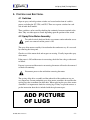
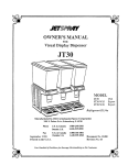
1
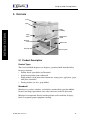
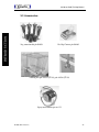
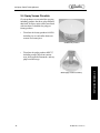
JET SPRAY (COLD)
TRAINING MANUAL
✔ CARBON DIOXIDE
✔ WATER
✔ SYRUP/CONCENTRATE
✔ MECHANICAL
✔ REFRIGERATION
✔ CONTROLS & ELECTRICAL
Jet Spray (Cold) Training Manual
Jet Spray (Cold)
Training Manual
The products, technical information, and instructions contained in this manual are subject
to change without notice. These instructions are not intended to cover all details or variations of the equipment, nor to provide for every possible contingency in the installation,
operation or maintenance of this equipment. This manual assumes that the person(s) working on the equipment have been trained and are skilled in working with electrical, plumbing, and mechanical equipment. It is assumed that appropriate safety precautions are taken
and that all local safety and construction requirements are being met, in addition to the
information contained in this manual.
To inquire about current revisions of this and other documentation or for assistance with
any Cornelius product contact:
IMI Cornelius Inc.
Corporate Headquarters
One Cornelius Place
Anoka, MN 55303-6234
U.S.A.
Internet:
www.cornelius.com
phone: 630-539-5050
888-248-5568
FAX:
Email:
[email protected]
630-539-5051
Trademarks and copyrights:
Aurora, Cornelius, Decade, Hydro Boost, Microban®, Olympus, Remcor, Sitco, Spirit,
UF-1, Vanguard, Venture, and Vista are registered trademarks of IMI Cornelius Inc.
Optifill trademark is pending.
This document contains proprietary information and it may not be
reproduced in any way without permission from Cornelius.
Printed in U.S.A.
Copyright © 2000, All Rights Reserved, IMI Cornelius Inc.
Jet Spray (Cold) Training Manual
TABLE OF CONTENTS
INTRODUCTION - - - - - - - - - - - - - - - - - - - - - - - - - - - - - - - - - - - - - - - - - - - - - - 1
Preview Questions - - - - - - - - - - - - - - - - - - - - - - - - - - - - - - - - - - - - - - - - - - - - - 1
Key Things To Know / Do - - - - - - - - - - - - - - - - - - - - - - - - - - - - - - - - - - - - - - - 2
Overview - - - - - - - - - - - - - - - - - - - - - - - - - - - - - - - - - - - - - - - - - - - - - - - - - - - 3
Product Description - - - - - - - - - - - - - - - - - - - - - - - - - - - - - - - - - - - - - - - - - 3
Product Types - - - - - - - - - - - - - - - - - - - - - - - - - - - - - - - - - - - - - - - - - - - 3
Microban® - - - - - - - - - - - - - - - - - - - - - - - - - - - - - - - - - - - - - - - - - - - - - 3
Dimensions & Capacities - - - - - - - - - - - - - - - - - - - - - - - - - - - - - - - - - - - - - - 4
JS7 Dispensers: - - - - - - - - - - - - - - - - - - - - - - - - - - - - - - - - - - - - - - - - - - 4
JT20 Dispensers: - - - - - - - - - - - - - - - - - - - - - - - - - - - - - - - - - - - - - - - - - 4
JT30 Dispensers: - - - - - - - - - - - - - - - - - - - - - - - - - - - - - - - - - - - - - - - - - 4
EJ1 Dispensers: - - - - - - - - - - - - - - - - - - - - - - - - - - - - - - - - - - - - - - - - - 4
J15 Dispensers: - - - - - - - - - - - - - - - - - - - - - - - - - - - - - - - - - - - - - - - - - - 4
Accessories - - - - - - - - - - - - - - - - - - - - - - - - - - - - - - - - - - - - - - - - - - - - - - - 5
SYSTEM DETAILS - - - - - - - - - - - - - - - - - - - - - - - - - - - - - - - - - - - - - - - - - - - - - 6
Water - - - - - - - - - - - - - - - - - - - - - - - - - - - - - - - - - - - - - - - - - - - - - - - - - - - - - 6
Water Quality - - - - - - - - - - - - - - - - - - - - - - - - - - - - - - - - - - - - - - - - - - - - - 6
Mechanical - - - - - - - - - - - - - - - - - - - - - - - - - - - - - - - - - - - - - - - - - - - - - - - - - - 6
Pump Assembly / Spray Drive Assembly - - - - - - - - - - - - - - - - - - - - - - - - - - - 6
Whipper Assembly - - - - - - - - - - - - - - - - - - - - - - - - - - - - - - - - - - - - - - - - - - 6
Whipper Conversion - - - - - - - - - - - - - - - - - - - - - - - - - - - - - - - - - - - - - - - - - 7
Spray Verses Circulate - - - - - - - - - - - - - - - - - - - - - - - - - - - - - - - - - - - - - - - 8
Refrigeration - - - - - - - - - - - - - - - - - - - - - - - - - - - - - - - - - - - - - - - - - - - - - - - - 9
Cooling Thermostat - - - - - - - - - - - - - - - - - - - - - - - - - - - - - - - - - - - - - - - - - 9
Compressor - - - - - - - - - - - - - - - - - - - - - - - - - - - - - - - - - - - - - - - - - - - - - - - 9
Condenser - - - - - - - - - - - - - - - - - - - - - - - - - - - - - - - - - - - - - - - - - - - - - - - - 9
Condenser Cleaning - - - - - - - - - - - - - - - - - - - - - - - - - - - - - - - - - - - - - - - - - 9
Filter Replacement - - - - - - - - - - - - - - - - - - - - - - - - - - - - - - - - - - - - - - - - - - 9
Condenser Fan - - - - - - - - - - - - - - - - - - - - - - - - - - - - - - - - - - - - - - - - - - - - - 9
Dryer - - - - - - - - - - - - - - - - - - - - - - - - - - - - - - - - - - - - - - - - - - - - - - - - - - - 9
Evaporators - - - - - - - - - - - - - - - - - - - - - - - - - - - - - - - - - - - - - - - - - - - - - - 10
Air Flow - - - - - - - - - - - - - - - - - - - - - - - - - - - - - - - - - - - - - - - - - - - - - - - - 10
Refrigeration Charging - - - - - - - - - - - - - - - - - - - - - - - - - - - - - - - - - - - - - - 10
Controls and Electrical - - - - - - - - - - - - - - - - - - - - - - - - - - - - - - - - - - - - - - - - - 11
Switches - - - - - - - - - - - - - - - - - - - - - - - - - - - - - - - - - - - - - - - - - - - - - - - - 11
Spray Drive Motor Assembly - - - - - - - - - - - - - - - - - - - - - - - - - - - - - - - - - - 11
TROUBLESHOOTING - - - - - - - - - - - - - - - - - - - - - - - - - - - - - - - - - - - - - - - - - 12
No Spray - - - - - - - - - - - - - - - - - - - - - - - - - - - - - - - - - - - - - - - - - - - - - - - - - - 12
Pump assembly - - - - - - - - - - - - - - - - - - - - - - - - - - - - - - - - - - - - - - - - - - - 12
Spray Drive Motor - - - - - - - - - - - - - - - - - - - - - - - - - - - - - - - - - - - - - - - - - 12
Noise in Pump Assembly - - - - - - - - - - - - - - - - - - - - - - - - - - - - - - - - - - - - - - - 13
Impella Spacing - - - - - - - - - - - - - - - - - - - - - - - - - - - - - - - - - - - - - - - - - - - 13
Breaking Magnetic Lock - - - - - - - - - - - - - - - - - - - - - - - - - - - - - - - - - - - - - 13
Pinch Tube Installation - - - - - - - - - - - - - - - - - - - - - - - - - - - - - - - - - - - - - - - - - 13
Bowl Leak - - - - - - - - - - - - - - - - - - - - - - - - - - - - - - - - - - - - - - - - - - - - - - - - - 14
Not Cooling - - - - - - - - - - - - - - - - - - - - - - - - - - - - - - - - - - - - - - - - - - - - - - - - 14
Thermostat - - - - - - - - - - - - - - - - - - - - - - - - - - - - - - - - - - - - - - - - - - - - - - 14
Condenser Cleaning - - - - - - - - - - - - - - - - - - - - - - - - - - - - - - - - - - - - - - - - 14
Condenser Fan Motor - - - - - - - - - - - - - - - - - - - - - - - - - - - - - - - - - - - - - - - 15
Condenser Fan Blade - - - - - - - - - - - - - - - - - - - - - - - - - - - - - - - - - - - - - - - 15
System Leak - - - - - - - - - - - - - - - - - - - - - - - - - - - - - - - - - - - - - - - - - - - - - 15
Refrigeration Troubleshooting - - - - - - - - - - - - - - - - - - - - - - - - - - - - - - - - - - - - 15
ATTACHMENTS - - - - - - - - - - - - - - - - - - - - - - - - - - - - - - - - - - - - - - - - - - - - - - 19
REVIEW - - - - - - - - - - - - - - - - - - - - - - - - - - - - - - - - - - - - - - - - - - - - - - - - - - - - 21
TABLE OF CONTENTS
Jet Spray (Cold) Training Manual
TABLE OF CONTENTS
Jet Spray (Cold) Training Manual
INTRODUCTION
1. PREVIEW QUESTIONS
Check your current knowledge by taking a few minutes to answer the following questions:
1. The 5 and 3-gallon bowl assemblies are interchangeable on certain models?
_____ True _____ False
2.
Parts that contain Microban need not be cleaned on a regular basis?
_____ True _____ False
3.
All visual cold units use only one type of circulator for all products that are dispensed
from the machine? _____ True _____ False
4.
Is it possible to add a whipper assembly to a unit after a unit has been purchased and
installed? _____ True _____ False
5.
The Spray Drive assembly needs to run in order to maintain proper product temperature? _____ True _____ False
© 2000, IMI Cornelius Inc.
-1-
Jet Spray (Cold) Training Manual
2. KEY THINGS TO KNOW / DO
Work Safely! Always unplug/disconnect the power to the dispenser before
servicing, and get help lifting the unit if it must be removed from the
counter !
✔
Make certain that you have adequate airflow around the unit for proper
operation !
✔
Learn to use a good quality volt-ohm meter. Proper electrical trouble shooting is impossible without it !
✔
Always read the installation and operation manuals before set up !
✔
Visual models are available in 3,5,8, and 15-gallon models !
✔
Whipper Assemblies are available for most models !
✔
Using the correct impella or circulator with the corresponding product will
give you the best visual display for the sale of the product !
✔
When product is in the bowls, the refrigeration unit must be operating to
preserve the integrity of the product !
✔
The Microban protection inhibits the growth of bacteria, mold, and mildew
that cause odors and stains !
© 2000, IMI Cornelius Inc.
INTRODUCTION
-2-
✔
Jet Spray (Cold) Training Manual
3. OVERVIEW
Cover
Bowl
INTRODUCTION
Pump
assembly
Spray
switch
Dispense
lever
Drip tray
Refrigeration
switch
Grill/air vent
Access panel
3.1 Product Description
Product Types
The visual cold drink dispenser can dispense a premixed drink from the follow
beverage selections:
• Powder based (sport drinks and Icsotonic)
• Syrup based product (non-carbonated)
• Pulpy products (fresh juice from concentrates; orange juice, apple juice, grapefruit juice, lemonade)
• Foamy products (ice teas, grape drinks)
Microban®
Microban is a tasteless, odorless, and colorless antimicrobial agent that inhibits
bacterial and fungal growth that cause odors and stains on the Jet Spray unit.
Microban is incorporated directly into the polymer used to mold the Jet Spray
bowls. It augments proper equipment cleaning.
© 2000, IMI Cornelius Inc.
-3-
Jet Spray (Cold) Training Manual
3.2 Dimensions & Capacities
-
-
-
-
-
-
-
-
-
-
- - - - - - - - - - - - - - - One
- - - - - - - - - - - 5 gal. (19 L)
- - 115 volt/60 Hz, 240 volt/50 Hz
- - - - 7 3/4” W, 26 5/8” H, 17” D
-197 mm W, 676 mm D, 432 mm D
- - - - - - - - - 54 lbs. (24.5 kg)
JT20 Dispensers:
Flavors: - - - Capacity: - - Voltages: - - - Dimensions: - - - - - - - - Shipping Weight:
-
-
-
-
-
-
-
-
-
-
- - - - - - - - - - - - - - - Two
- - - - - - - - two – 5 gal. (19 L)
- - 115 volt/60 Hz, 240 volt/50 Hz
- - - - - 16” W, 26 5/8” H, 17” D
-407 mm W, 676 mm D, 432 mm D
- - - - - - - - - - 75 lbs. (34 kg)
JT30 Dispensers:
Flavors: - - - Capacity: - - Voltages: - - - Dimensions: - - - - - - - - Shipping Weight:
-
-
-
-
-
-
-
-
-
-
- - - - - - - - - - - - - - Three
- - - - - - - three – 5 gal. (19 L)
- - 115 volt/60 Hz, 240 volt/50 Hz
- - - 24 1/2” W, 26 5/8” H, 17” D
-622 mm W, 676 mm D, 432 mm D
- - - - - - - - - 93 lbs. (42.2 kg)
EJ1 Dispensers:
Flavors: - - - Capacity: - - Voltages: - - - Dimensions: - - - - - - - - Shipping Weight:
-
-
-
-
-
-
-
-
-
-
- - - - - - - - - - - - - - Single
- - - - - - - - - - - 8 gal. (30 L)
- - 115 volt/60 Hz, 240 volt/50 Hz
- - - - - - - 16” W, 31” H, 18” D
-407 mm W, 788 mm D, 457 mm D
- - - - - - - - - 79 lbs. (35.8 kg)
J15 Dispensers:
Flavors: - - - Capacity: - - Voltages: - - - Dimensions: - - - - - - - - Shipping Weight:
-
-
-
-
-
-
-
-
-
-
- - - - - - - - - - - - - - - One
- - - - - - - - - - 15 gal. (57 L)
- - 115 volt/60 Hz, 240 volt/50 Hz
- - - - - - - 16” W, 31” H, 18” D
-407 mm W, 788 mm D, 457 mm D
- - - - - - - - - 79 lbs. (35.8 kg)
© 2000, IMI Cornelius Inc.
INTRODUCTION
-4-
JS7 Dispensers:
Flavors: - - - Capacity: - - Voltages: - - - Dimensions: - - - - - - - - Shipping Weight:
Jet Spray (Cold) Training Manual
INTRODUCTION
3.3 Accessories
Leg extension kit p/n S4056
No Cup Contact p/n S6469
Locking Kit p/n A3035 (JT-20), p/n A3036 (JT-30)
Spray Drive Motor p/n A1753
© 2000, IMI Cornelius Inc.
-5-
Jet Spray (Cold) Training Manual
SYSTEM DETAILS
1. WATER
1.1 Water Quality
2. MECHANICAL
2.1 Pump Assembly / Spray Drive Assembly
All units designed to spray, including those with optional whippers, incorporate a
unique refrigeration design that keeps drinks consistently colder at any bowl level.
The beverage is constantly circulated through the pump housing over the cooling
evaporators.
2.2 Whipper Assembly
Jet Spray's optional, patented whipper aerates and whips the beverage before it
leaves the bowl. This exclusive whipping process is the most sanitary in the industry, keeping the beverage under refrigeration at all times, even during whipping.
Each serving is individually whipped and overruns of 35%-40% are obtained with
most specially formulated whipped drink bases.
A simple external adjustment allows the amount of overrun or foam head to be
varied as desired. The patented whipper is held securely in place magnetically and
can be easily slipped in and out of the bowl for changeover from whipped to nonwhipped drinks.
If drinks are not being whipped:
• Make sure refrigeration switch is on.
• Assure the whipper motor runs when depressing the dispense lever.
• Make sure whipper chamber assembly is located in the proper position and
resting flat on a base of bowl.
• Check whipper magnet. It should turn freely, if not, remove impella support
pin and clean all parts with soap and water.
-6-
© 2000, IMI Cornelius Inc.
INTRODUCTION
Water quality has an affect on juice dispensing systems.
• odor
• taste
• clarity/foaming
Water filtration is recommended to assure the best beverage taste.
Jet Spray (Cold) Training Manual
•
Check whipper switch for adjustment. If moved too far forward, an air lock
may occur, thereby breaking the magnetic lock between whipper motor and
whipper chamber assembly.
To adjust whipper switch, loosen screw to the right of the switch. Slide switch in
slot to desired location.
NOTE: When switch is moved to the forward position (out towards operator)
whipper motor will come on with very little movement of the push handle.
When switch is all the way back (towards front panel) whipper motor will
not come on, even when the handle is pushed all the way back.
2.3 Whipper Conversion
SYSTEM DETAILS
1. Disconnect power.
2. Drain bowl.
3. Remove pinch tube, bowl, dispense lever, drip tray, switch cover plate, and
front panel.
4. Install washer and standoff into the whipper motor mounts on condensate tray.
5. Install whipper motor assembly and fasten with 3 keps nuts.
6. Wire according to diagram.
NOTE: Use existing cable clamps and wire ties provided to route wires away from
sharp edges and fan blade.
7. Attach new wiring diagram to new front panel.
8. Install new front panel with existing hardware.
9. Install switch cover plate with switch to condensate tray in front of whipper
motor assembly (use 10-32 x 1 1/4” screw and spacer).
10. Attach whipper decal on raised boss of condensate tray where whipper motor
was installed.
11. Replace bowl, new dispense lever, pinch tube, and whipper chamber assembly
and drip tray. When placing the whipper assembly into the bowl, assure that it
is located into the recess directly above the whipper decal. Then insert the 90°
elbow into the pinch tube.
12. Connect power, premix product, and add product to bowls.
© 2000, IMI Cornelius Inc.
-7-
Jet Spray (Cold) Training Manual
2.4 Spray Verses Circulate
Certain products are not suited for spraying,
including products that have pulp and those
that foam. Jet Spray units can be retro-fitted
with circulator assemblies for pulpy or
foamy products.
•
Circulator for foamy products #A1620,
including ice tea and coffee from concentrate and some juice.
#A1620 foamy circulator
•
Circulator for pulpy products #S6737,
including orange juice from concentrate, fresh squeezed lemonade, and any
pulp based beverage.
-8-
© 2000, IMI Cornelius Inc.
SYSTEM DETAILS
#S6737 pulpy circulator assembly
Jet Spray (Cold) Training Manual
3. REFRIGERATION
3.1 Cooling Thermostat
There is one thermostat on all of the cold product units. This thermostat is located
against the evaporator coil of the unit. On the JT20 and JT30 units the thermostat is
mounted against the right hand evaporator coil when facing the front of the unit.
The cooling or frost pattern for the JT30 flows from the center to the left then to
the right. Upon reaching a predetermined temperature, the unit will cycle. All thermostats are factory set and normally need no adjustment.
3.2 Compressor
Moves the refrigerant through the system. Pressurizes the refrigerant for heat dissipation in the condenser and ultimately heat removal by evaporation in the bowl’s
evaporator.
3.3 Condenser
Dissipates heat from the compressor and prepares the high pressure refrigerant for
the capillary tube and ultimately the evaporator.
SYSTEM DETAILS
3.4 Condenser Cleaning
It is very important to do this on an annual basis and as required. The condenser
can be cleaned with a brush or compressed air. There are commercial condenser
cleaners on the market that are acceptable.
3.5 Filter Replacement
The Jet Spray unit comes with a foam type filter mounted on the inside of the side
panel assembly. JT30 models have a filter mounted inside the rear panel of the
chassis. These filters should be periodically removed and washed in warm soapy
solution to remove dust and derbies.
3.6 Condenser Fan
Draws air through the condenser coils and over the compressor to facilitate heat
removal.
3.7 Dryer
Cleans and removes moisture from the refrigeration system. The dryer should
always be replaced whenever servicing or opening a refrigeration system. When
ordering a dryer, specify model number and refrigerant type (or serial number) to
insure the correct dryer is received.
© 2000, IMI Cornelius Inc.
-9-
Jet Spray (Cold) Training Manual
3.8 Evaporators
There are two types of evaporators on the Jet Spray cold products, coil and dome.
It is important on both to remember to keep product above the top of the coils to
insure proper cooling of the product and correct operation of the cooling system.
Sometimes there is an ice build up around the evaporator. This is normal.
When operating a multiple bowl unit, it is necessary to have liquid above the level
of the evaporators in each bowl, this balances the refrigeration unit. Never run with
an empty bowl, fill with water if product is unavailable.
3.9 Air Flow
It is very important to make sure that there is adequate air circulation around the
machine. There should be a minimum of three inches of space all around the unit.
Refer to the installation and owners manuals for additional information.
3.10 Refrigeration Charging
Charging the capillary tube controlled system requires accurate charging equipment and technique. The amount of refrigerant in the system determines the operating pressures and temperature of the evaporators. It is necessary to utilize a
refrigerant scale or graduated charging cylinder when charging the system.
NOTE: Hooking up a high side hose to a system with a low charge causes a quarter
or more of the charge to backup into the hose. This results in an incorrect
reading. This is why operating pressures are not normally published.
- 10 -
© 2000, IMI Cornelius Inc.
SYSTEM DETAILS
Load, ambient temperature, and operating conditions affect sealed system operating pressures. If the unit appears under charged, check for a dirty condenser. If the
unit is running constantly but not cooling, the problem may be a low charge. If a
low charge is suspected, it is recommended that the system is evaluated and leak
tested.
Jet Spray (Cold) Training Manual
4. CONTROLS AND ELECTRICAL
4.1 Switches
Separate spray and refrigeration switches are located on the front of each dispenser, excluding the JS7, JW6, and JW5. There are separate switches for each
side of multi-bowl models.
These switches can be tested by checking the continuity from one terminal to the
other. They are either open or closed depending upon the position of the switch.
4.2 Spray Drive Motor Assembly
To avoid electrical shock and death, use extreme caution when the access
panels are removed and the power is ON.
The spray drive motor assembly is located under the condensate tray. It is accessed
by removing the front panel.
Check to see if the motor shaft and magnet are rotating. Visually inspect the spray
drive motor.
If the power is ON and the motor is not rotating, check for line voltage at the terminal board.
If power is present and the motor is not rotating, the motor will need to be removed
to check for continuity.
Disconnect power to the unit before removing the motor.
The spacing of the drive assembly and the underside of the condensate tray are
very important. Current production spray drive motor assemblies do not utilize the
spacing lugs that are mounted in older units. When replacing the spray drive motor
assemblies it is important to check for existing lugs. If they are present remove as
per the instruction sheet that is included with the replacement part.
$''3,&785(
2)/8*6
© 2000, IMI Cornelius Inc.
- 11 -
Jet Spray (Cold) Training Manual
TROUBLESHOOTING
1. NO SPRAY
1.1 Pump assembly
Be sure the spray switch is ON
Check impella magnet. Impella should spin freely. If it does not, remove and clean
both impella and support pin.
NOTE: Check that the Impella assembly is in upright position, fins facing upward.
Sugar and solids can crystallize and cause impella to bind. Do not allow these
materials to dry on parts.
Bearing in impella could be worn causing impella to scrap the base of the bowl.
Replace the impella assembly.
NOTE: Switch must be OFF when inserting the impella into the bowl to insure
magnetic coupling.
With the JS/JT/JWT series, assure that the pump housing is locked into place. If
either of the tabs located on the bottom perimeter of the pump housing assembly
are broken, the pump will not spray properly. With the TJ/EJ/J15 series, the pump
cover should be locked under all three bowl lugs. If any of these are broken the
pump will not spray properly and will vibrate and be noisy. Replace the bowl
assembly or use the Jet-Spray Circulator #S6737.
1.2 Spray Drive Motor
To check the spray power source, remove front splash panel or side panels,
depending on the model, by removing the screws. This will expose the spray drive
assembly. The drive assembly must spin freely. If shaft or magnet rubs or binds,
adjust or replace it.
The spray drive motor must run in a counterclockwise direction.
If the motor is stopped or not up to speed it will affect circulation and temperature
of the drink. Replace spray switch or spray drive motor.
- 12 -
© 2000, IMI Cornelius Inc.
SYSTEM DETAILS
Long pieces of pulp may plug impella and bind the impella blades. Juices with
excessive pulp must be strained in order to spray. If it is desired to retain pulp, use
the Jet-Spray Circulator #S6737 in place of the pump.
Jet Spray (Cold) Training Manual
2. NOISE IN PUMP ASSEMBLY
2.1 Impella Spacing
Correct installation and maintenance of the impella is very important to efficient
operation and the appearance of the product in the bowl.
2.2 Breaking Magnetic Lock
The operation of the spray drive motor and impella is simple. The two magnets,
one on the spray drive motor and one on the impella assembly, “lock” these components together. When that lock is broken it creates noise and/or an improper
pumping action. The alignment of the two components is to correct and efficient
operation.
Problems that cause that loss of magnet alignment include:
• Improper product mix
• Worn bearing on the impella unit
• Worn impella pin or shaft
• Bowl assembly not correctly seated on the chassis
• Impella installed upside down
• Pumps not being run, allowing solids to settle in the bottom of the bowl.
Both the pump refrigeration switches should be on whenever product is in the
bowl.
TROUBLE SHOOTING
3. PINCH TUBE INSTALLATION
1. Remove pinch tubes from the plastic bag and wash with warm and mild detergent or soap.
2. Visually check for cuts or holes in the pinch tube assembly.
3. Wet bowl spout surface and sealing rings on the pinch tube.
4. With one hand, push back dispense lever until it touches the front panel. With
the other hand, pick up pinch tube and carefully insert tube into bowl spout
opening, and into lower handle support spout. Make sure end of tube does not
get caught on edge above handle support spout opening.
5. Push pinch tube into bowl spout opening with thumb. When end of tube passes
beyond bottom of dispense lever support spout opening, pull end of tube for
final seating of pinch tube top into bowl spout seat. Make sure the tube is free
of wrinkles. Tube should extend ¼" below support spout.
6. Install other pinch tubes on the unit if needed.
© 2000, IMI Cornelius Inc.
- 13 -
Jet Spray (Cold) Training Manual
4. BOWL LEAK
NOTE: Do not confuse condensation drippings on the outside of the bowl as leaks.
High humidity causes more condensation.
1. Be sure the gaskets are properly placed in the grooves on the bowl and that
there are no tears or cuts in the gaskets.
2. Check for foreign material around domes where gaskets seat.
3. Check pinch tubes for holes or tears above the pinch off area, or for improper
insertion.
4. Be sure condensate washers are around bowl spouts. Condensation will run
down the bowl spout/pinch tube area giving the appearance of leaks if they are
not in place.
5. NOT COOLING
5.1 Thermostat
The thermostat is pre-set at the factory and will not normally require resetting. The
unit will automatically cycle between the high and low temperatures of the thermostat.
A continuity check of the thermostat will determine if it has failed.
Be sure to replace the thermostat capillary tube to the correct depth in the thermal
well. This is essential to the sensing of the correct evaporator temperature.
The capillary tube well is sealed with a permagum sealant to protect the bulb of the
thermostat from being affected by internal or ambient temperature changes.
NOTE: These thermostats can and often due contain a caustic solution
within the bulb and should be disposed of in a professional manner to
prevent injury or damage.
5.2 Condenser Cleaning
1. Turn switch OFF and unplug the unit.
2. Remove right or left side panel (plus back panel on JT30 model) and clean thoroughly.
3. With a stiff bristle brush or vacuum cleaner, clean condenser. Be sure no loose
dirt goes into the dispenser.
- 14 -
© 2000, IMI Cornelius Inc.
TROUBLE SHOOTING
The condenser must be cleaned periodically to insure efficient operation. The frequency of cleaning will depend on the location. No applicable buildup on the condenser fins should be allowed.
Jet Spray (Cold) Training Manual
4. Replace side panels and restart unit.
5.3 Condenser Fan Motor
The condenser fan motor is sealed at the factory and needs no lubrication. The
motor can be checked in two ways; check for continuity, and check to see that
power is present at the terminal block or terminal strip.
5.4 Condenser Fan Blade
The condenser fan blade pulls air through the condenser. If the blade is damaged or
is not positioned correctly in the condenser shroud, the blade will not pull or push
the correct amount of air to cool the condenser coil, reducing refrigeration efficiency.
5.5 System Leak
Symptoms of a refrigerant leak include a running compressor with a hot suction
line and the compressor running excessively hot, and an increased amp draw by
the compressor. A sweep of the refrigeration system is necessary to determine if
there is a leak.
If there is a leak in the system, it must be evacuated and repaired by an certified
refrigeration technician. The system must then be pulled down to a vacuum and
recharged with the correct level of refrigerant.
6. REFRIGERATION TROUBLESHOOTING
PROBLEM (fault)
TROUBLE SHOOTING
1. Compressor will not
start, no humming
noise
© 2000, IMI Cornelius Inc.
CAUSE (diagnosis)
ACTION (remedy)
A. Line disconnect switch
open
B. Fuse removed/blown
C. Overload protection
tripped
D. Control stuck in open
position
E. Control OFF due to
cold location
F. Wiring improper or
loose
A. Close start or disconnect switch
B. Replace fuse
C. Refer to electrical servicing
D. Repair or replace control
E. Relocate control
F. Check wiring against
diagram
- 15 -
Jet Spray (Cold) Training Manual
PROBLEM (fault)
2. Compressor will not
start — hums but trips
overload protector
3. Compressor starts but
start winding does not
switch off
CAUSE (diagnosis)
A.
B.
C.
D.
Improperly wired
Low voltage to unit
Relay not closing
Compressor motor
winding open or
shorted
E. Internal mechanical
trouble in compressor
F. Liquid refrigerant in
compressor
A. Check wiring against
diagram
B. Correct problem
C. Correct problem
D. Replace compressor
A. Improperly wired
A. Check wiring against
diagram
B. Correct problem
C. Correct problem
D. Check discharge shutoff valve, possible
overcharge, or insufficient condenser cooling
E. Replace compressor
B. Low voltage to unit
C. Relay failed to open
D. Excessively high discharge pressure
E. Compressor has winding open or shorted
F. Internal mechanical
trouble in compressor
4. Compressor starts but
then short-cycles on
overload protector
A. Additional current
passing thru overload
protector
B. Overload protector
defective
C. Excessive discharge
pressure
D. Suction pressure too
high
E. Replace compressor
F. Add crankcase heater
and/or accumulator
F. Replace compressor
A. Check wiring diagram;
check for added fan
motors, pumps, etc.
connected to wrong
side of connector
B. Check current, replace
protector
C. Check ventilation,
restrictions in cooling
medium or refrigeration system
D. Check for possible misapplication, use stronger unit
E. Check refrigerant
charge and add if necessary (fix leak first)
F. Replace compressor
© 2000, IMI Cornelius Inc.
TROUBLE SHOOTING
E. Compressor too hot,
return gas hot
F. Compressor has winding open or shorted
- 16 -
ACTION (remedy)
Jet Spray (Cold) Training Manual
PROBLEM (fault)
CAUSE (diagnosis)
5. Unit runs OK but short- A. Overload protector
cycles on
B. Thermostat
6. Unit operates long or
continuously
7. Relay defective or
burned out
A. See “Compressor starts
but then short-cycles
on overload protector”
above
B. Widen differential
A. Refrigerant low
B. Control contacts stuck
closed
C. Refrigerated or air conditioned space has
excessive load or poor
insulation
D. System is inadequate to
handle the load
E. Evaporator coil iced
F. Restriction in refrigeration system
G. Dirty condenser
H. Filter dirty
A. Fix leak and charge
B. Clean contacts or
replace control
C. Correct problem
A. Incorrect relay
A. Replace with correct
relay
B. Remount in correct
position
C. Correct problem
B. Incorrect mounting
angle
C. Line voltage too high
or low
D. Excessive short cycling
E. Relay mounting loose
F. Incorrect run capacitor
TROUBLE SHOOTING
ACTION (remedy)
D. Replace with larger
system
E. Defrost
F. Determine location and
remove
G. Clean condenser
H. Clean or replace filter
D. Correct problem (see
“Unit runs OK but
short-cycles on” above)
E. Mount correctly
F. Replace with correct
capacitor
8. Suction line frosted or
sweating
A. Refrigerant overcharge
A. Correct charge
9. Liquid line frosted or
sweating
A. Restriction in dehydrator or strainer
A. Replace bad part
© 2000, IMI Cornelius Inc.
- 17 -
Jet Spray (Cold) Training Manual
PROBLEM (fault)
9. Unit noisy
A. Loose parts or mounting
B. Tubing rattle
C. Bent fan blade vibrating
D. Worn fan motor bearings
ACTION (remedy)
A. Tighten
B. Reform tubing
C. Replace blade
D. Replace motor
© 2000, IMI Cornelius Inc.
TROUBLE SHOOTING
- 18 -
CAUSE (diagnosis)
Jet Spray (Cold) Training Manual
ATTACHMENTS
The following attachments should be included with this lesson:
TROUBLE SHOOTING
JetSpray Care And Cleaning Instructions
© 2000, IMI Cornelius Inc.
- 19 -
ATTACHMENTS
Jet Spray (Cold) Training Manual
Microban Antibacterial Protection
- 20 -
© 2000, IMI Cornelius Inc.
ATTACHMENTS
Jet Spray (Cold) Training Manual
REVIEW
DATE: _______________________________________________
NAME: _______________________________________________
LOCATION: __________________________________________
The following questions summarize important points in this training lesson.
1. It is acceptable to run the system with only one of the two bowls with product in it.
_____ True
_____ False
2.
Pinch tubes should be cleaned regularly and replaced twice a year.
_____ True
_____ False
3.
Whipper assemblies are can not be added to a unit after it has left the factory.
_____ True
_____ False
4.
Plastic components are dishwasher safe.
_____ True
_____ False
5.
Microban is tasteless, colorless, and odorless.
_____ True
_____ False
6.
With Microban added to components it is no longer necessary to clean and sanitize
units.
_____ True
_____ False
7.
Describe the three types of circulators for Jet Spray units.
____________________________________________________________________
____________________________________________________________________
____________________________________________________________________
____________________________________________________________________
© 2000, IMI Cornelius Inc.
- 21 -
Jet Spray (Cold) Training Manual
8.
What direction does the refrigerant flow during initial startup?
____________________________________________________________________
____________________________________________________________________
9.
What direction does the refrigerant flow during the cooling cycle?
____________________________________________________________________
____________________________________________________________________
10. When do thermostats need to be adjusted?
____________________________________________________________________
____________________________________________________________________
12. Ice buildup on the evaporator is:
A. normal
B. due to the thermostat being set too low
C. an indication of improper product mix
D. all of the above.
13. It is recommended that the pump mix the product instead of pre-mixing it.?
_____ True
_____ False
- 22 -
© 2000, IMI Cornelius Inc.
REVIEW
11. Do pump assemblies need to be inside the bowl to keep the product cool?
____________________________________________________________________
____________________________________________________________________
Jet Spray (Cold) Training Manual
NOTES:
_______________________________________________________________________
_______________________________________________________________________
_______________________________________________________________________
_______________________________________________________________________
REVIEW
_______________________________________________________________________
_______________________________________________________________________
_______________________________________________________________________
_______________________________________________________________________
_______________________________________________________________________
_______________________________________________________________________
_______________________________________________________________________
_______________________________________________________________________
_______________________________________________________________________
_______________________________________________________________________
_______________________________________________________________________
_______________________________________________________________________
_______________________________________________________________________
_______________________________________________________________________
_______________________________________________________________________
_______________________________________________________________________
_______________________________________________________________________
© 2000, IMI Cornelius Inc.
- 23 -
IMI Cornelius, Inc.
www.cornlius.com
Part No. TP00936
March 9, 2000